UNIT V GROUP TECHNOLOGY AND CAPP - WordPress.com...UNIT III GROUP TECHNOLOGY AND CAPP History Of...
59
BTME 505 CAD/CAM/CIM UNIT V – GROUP TECHNOLOGY AND CAPP 1
Transcript of UNIT V GROUP TECHNOLOGY AND CAPP - WordPress.com...UNIT III GROUP TECHNOLOGY AND CAPP History Of...
BTME 505 CAD/CAM/CIM
UNIT V – GROUP TECHNOLOGY AND CAPP
1
UNIT III GROUP TECHNOLOGY AND CAPP
History Of Group Technology – role of G.T in CAD/CAM Integration –
part families classification and coding – DCLASS and MCLASS and
OPTIZ coding systems – facility design using G.T – benefits of G.T –
cellular manufacturing. Process planning - role of process planning in
CAD/CAM Integration – approaches to computer aided process
planning – variant approach and generative approaches – CAPP and
CMPP systems.2

GROUP TECHNOLOGY (GT)
GT is a manufacturing philosophy in which similar parts are
identified & grouped together to make advantage of their similarities
in design and production.
Similar parts bare arranged into part families, where each part family
possesses similar design and/or manufacturing characteristics.
Grouping the production equipment into machine cells, where each
cell specializes in the production of a part family, is called cellular
manufacturing3

History of GT
• 1925 – F.W.Taylor need for standardization, inspection and supervision
• 1925 – R.Flanders presented a paper in ASME about organisationingmanufacturing, USA.
• 1937 – A.sokolovskiy essential features of GT at Soviety Union
• 1949 – A.korling of Sweden presented a paper in paris “Group Productiion”
• 1959 – S.P Mitrofanov a Russian, Published a book entitled “Scientific Principal ofGT”
• 1960 – west german and Great Britain started serios studies about GT technology
H.opitz german researcher, studied work parts manufactured and codingsystem
• 1963 – Concept of GT is well recognized and widely applied in many industries
• 1990 – concepts of CMS involved4
Implementing Group Technology (GT)
1. Identifying the part families If the plant makes 10,000 different
parts, reviewing all of the part drawings and grouping the parts
into families is a substantial task that consumes a significant
amount of time.
2. Rearranging production machines into cells It is time
consuming and costly to plan and accomplish this rearrangement,
and the machines are not producing during the change over.
5
Part Families
• Part family - Group of similar parts
• Machine cell - Group of machineries used to process an
individual part family
• Part family is a Collection of parts that are similar either
because of geometric shape and size or because similar
processing steps are required in their manufacture.
6

Part FamiliesSimilar prismatic parts requiring similar milling operations
Dissimilar parts requiring similar machining operations (hole drilling, surfacemilling
Identical designed parts requiring completelydifferent manufacturing processes
7

• One of the important manufacturing advantages of grouping work
parts into families can be explained with reference to figures below
8
METHODS FOR PART FAMILY
There are three general methods for solving part families grouping. All
the three are time consuming and involve the analysis of much of data
by properly trained personnel. The three methods are:
Visual inspection.
Parts classification and coding.
Production flow analysis.
9
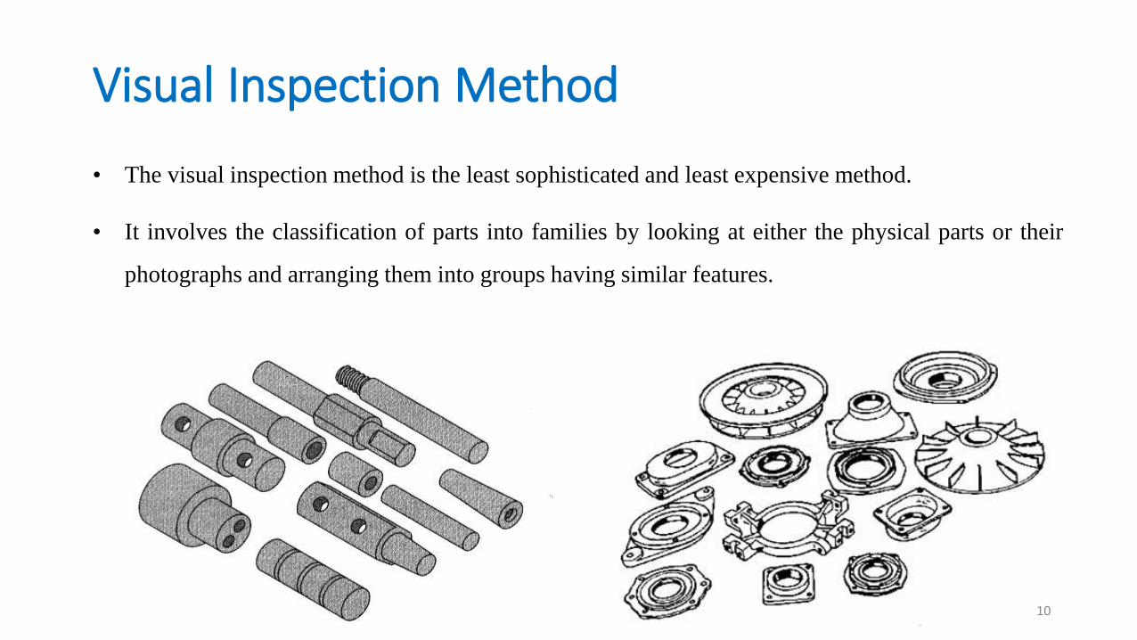
Visual Inspection Method
• The visual inspection method is the least sophisticated and least expensive method.
• It involves the classification of parts into families by looking at either the physical parts or their
photographs and arranging them into groups having similar features.
10
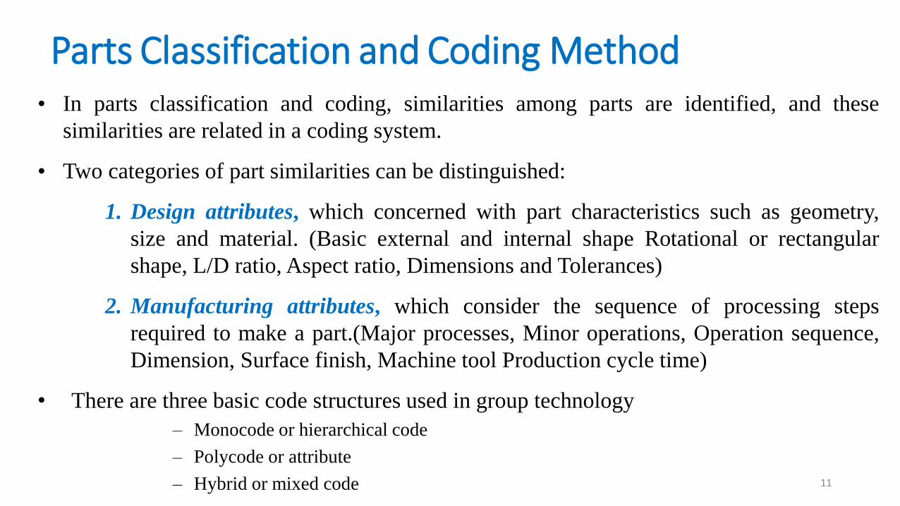
Parts Classification and Coding Method• In parts classification and coding, similarities among parts are identified, and these
similarities are related in a coding system.
• Two categories of part similarities can be distinguished:
1. Design attributes, which concerned with part characteristics such as geometry,
size and material. (Basic external and internal shape Rotational or rectangular
shape, L/D ratio, Aspect ratio, Dimensions and Tolerances)
2. Manufacturing attributes, which consider the sequence of processing steps
required to make a part.(Major processes, Minor operations, Operation sequence,
Dimension, Surface finish, Machine tool Production cycle time)
• There are three basic code structures used in group technology
– Monocode or hierarchical code
– Polycode or attribute
– Hybrid or mixed code 11
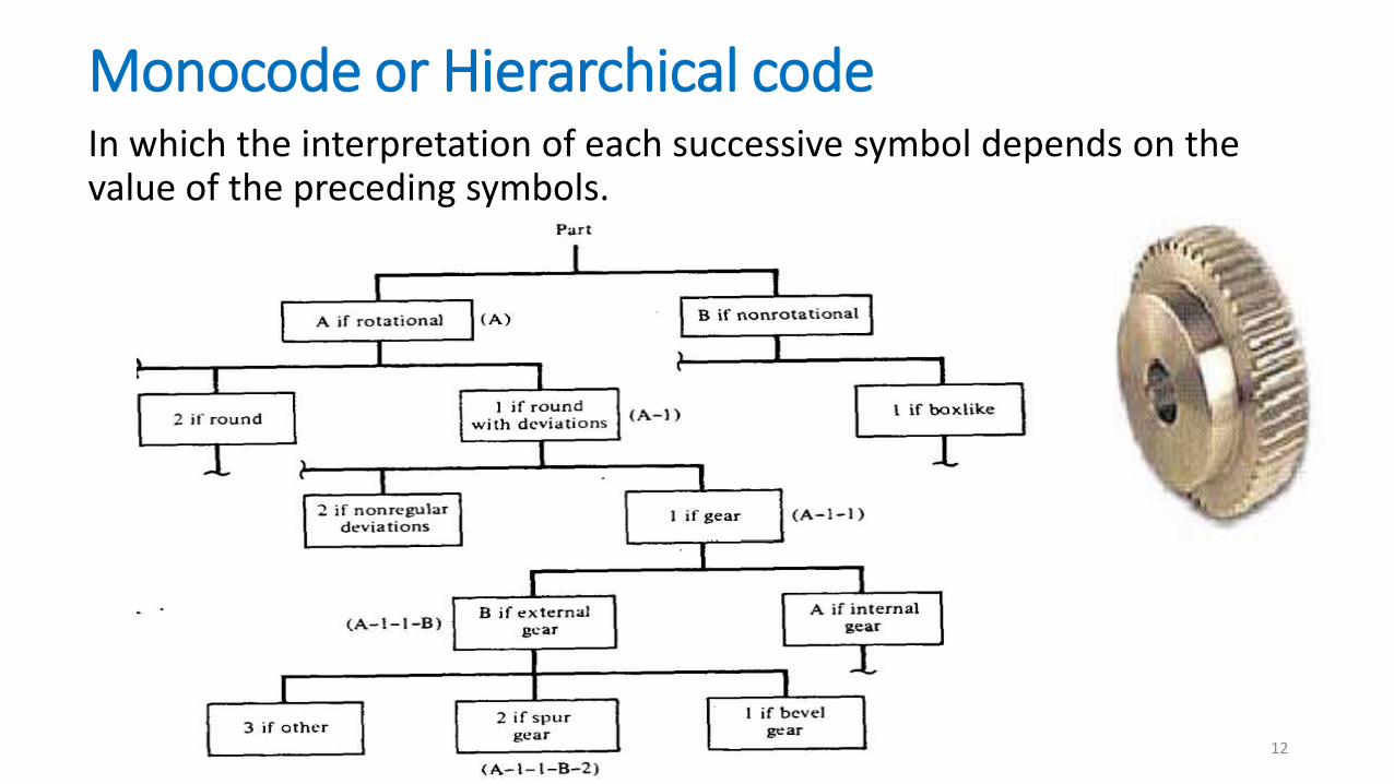
Monocode or Hierarchical codeIn which the interpretation of each successive symbol depends on the value of the preceding symbols.
12
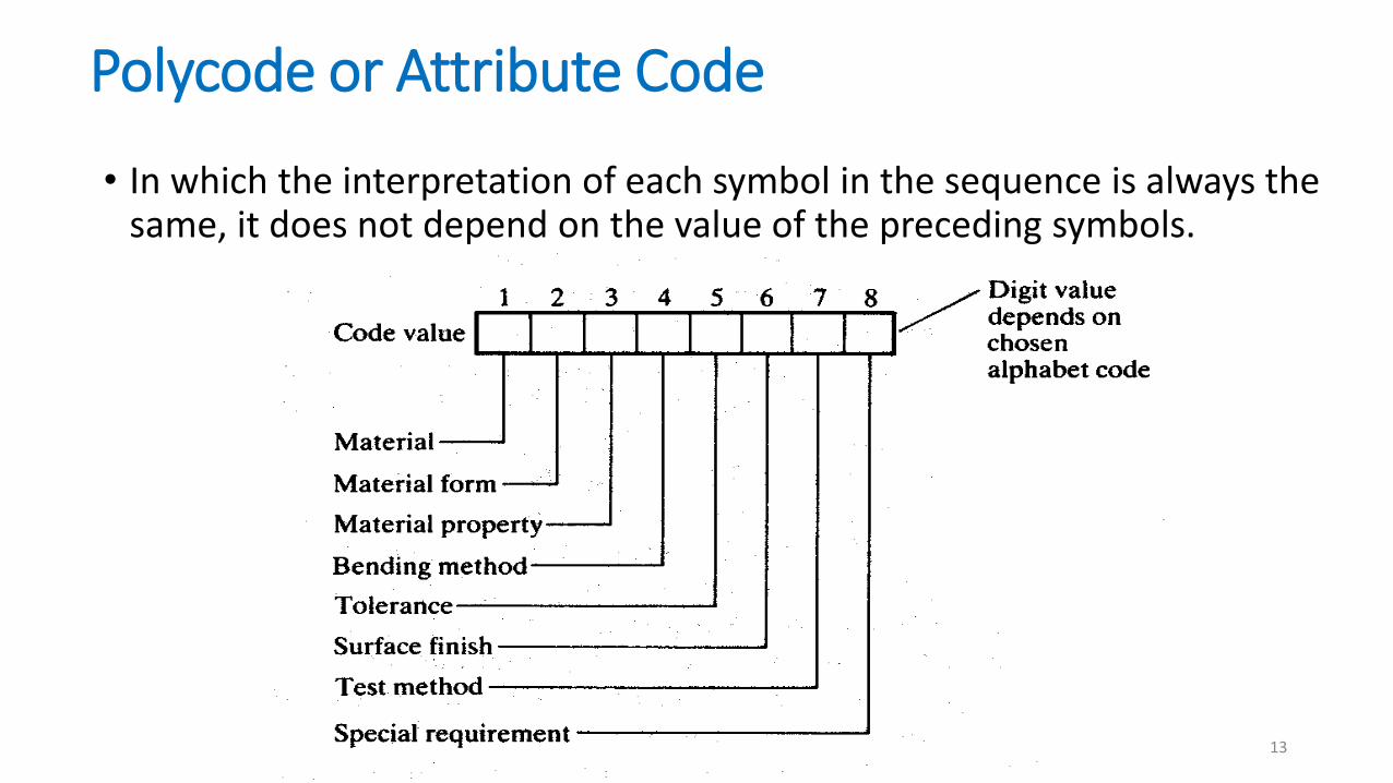
Polycode or Attribute Code
• In which the interpretation of each symbol in the sequence is always the same, it does not depend on the value of the preceding symbols.
13
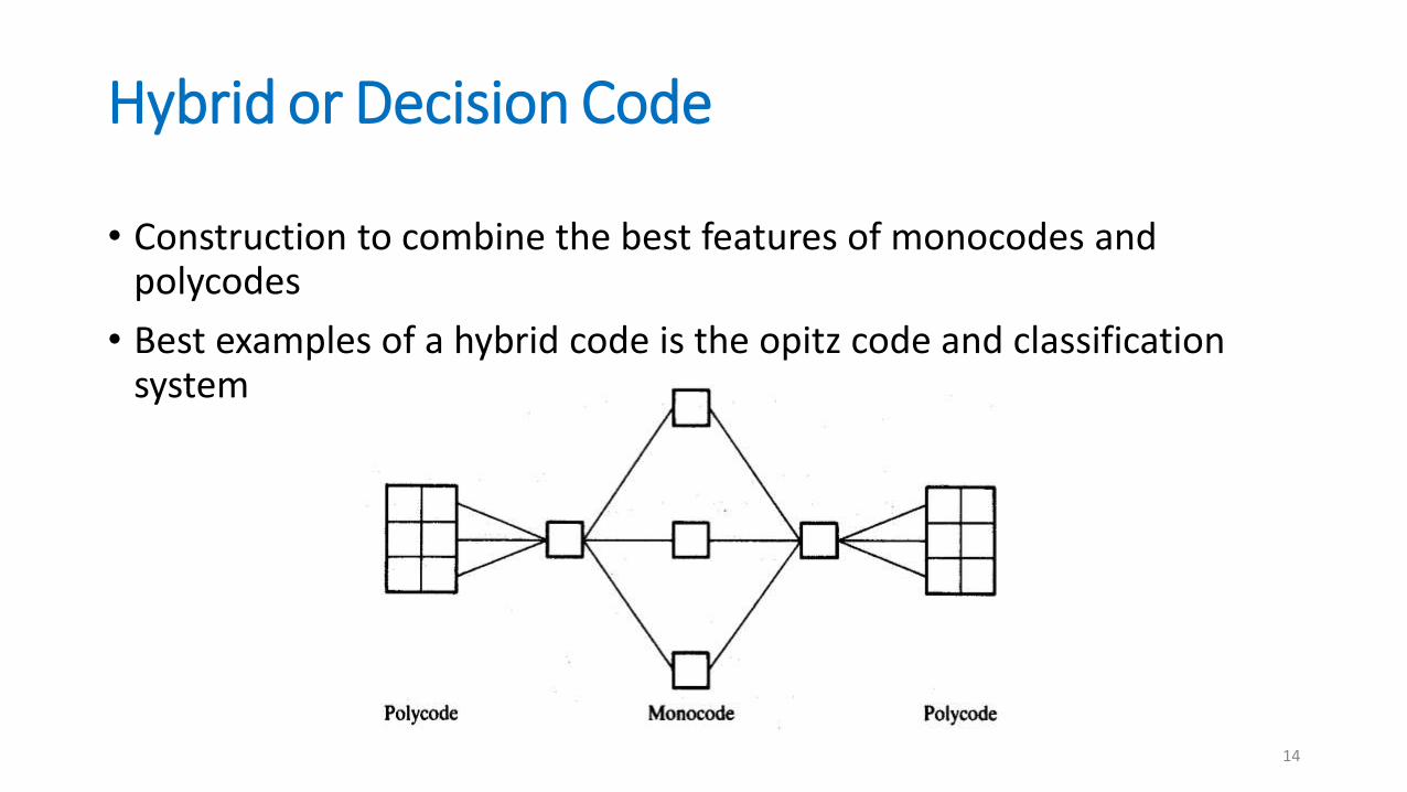
Hybrid or Decision Code
• Construction to combine the best features of monocodes and polycodes
• Best examples of a hybrid code is the opitz code and classification system
14

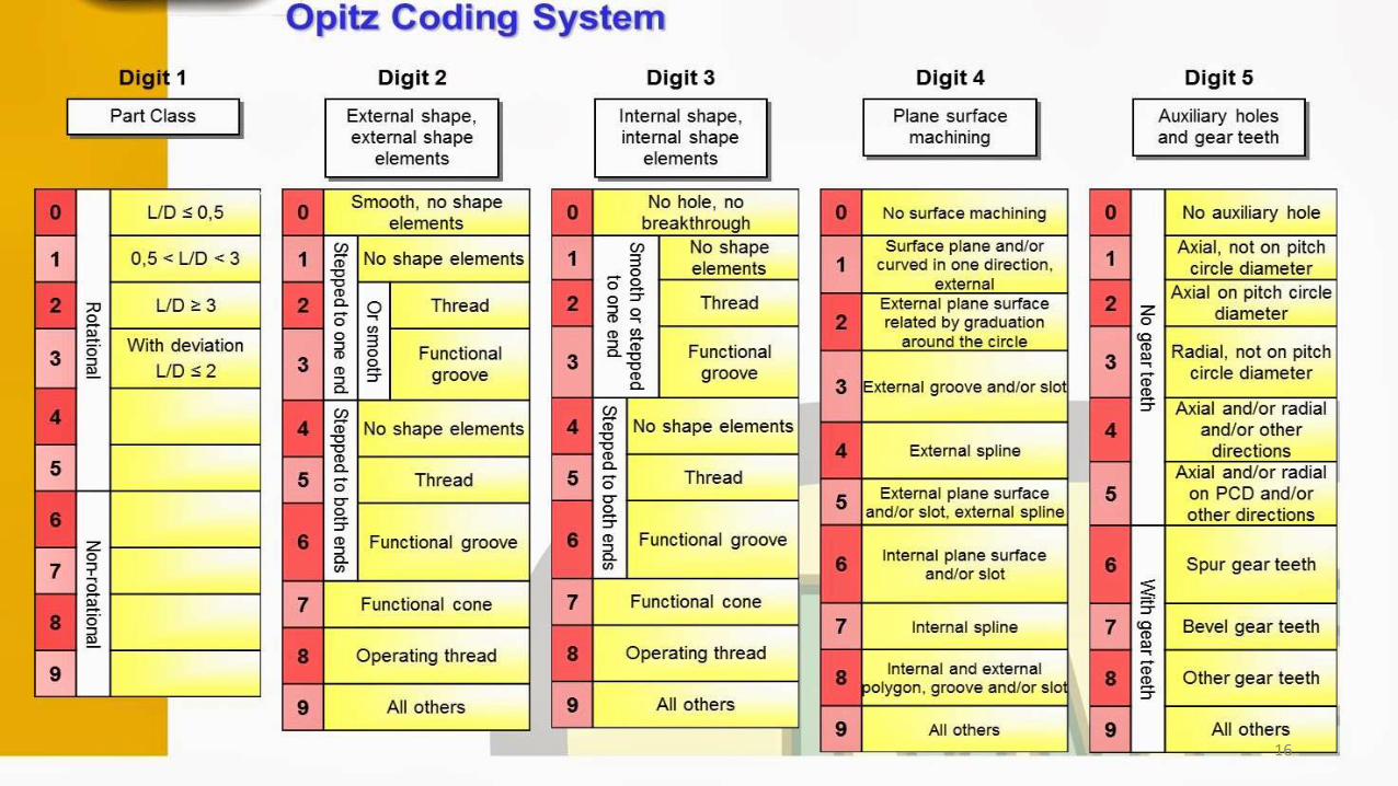
Opitz Classification System (H.opitz university of Aachen in Germany)
Form Code 1 2 3 4 5 for design attributes
Supplementary Code 6 7 8 9 for manufacturing attributes
Secondary Code A B C D for production operation type & sequence
15
16
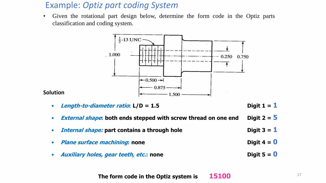
Example: Optiz part coding System• Given the rotational part design below, determine the form code in the Optiz parts
classification and coding system.
Solution
• Length-to-diameter ratio: L/D = 1.5 Digit 1 = 1
• External shape: both ends stepped with screw thread on one end Digit 2 = 5
• Internal shape: part contains a through hole Digit 3 = 1
• Plane surface machining: none Digit 4 = 0
• Auxiliary holes, gear teeth, etc.: none Digit 5 = 0
The form code in the Optiz system is 15100 17

MICLASS System• It stands for Metal Institute Classification system and developed by Netherlands
Organization for Applied Scientific research. It is referred as Multiclass system.
• MICLASS classification range from 1 to 30 digits. Universal code the first 12 digits code and next 18 digits are Supplementary code
18
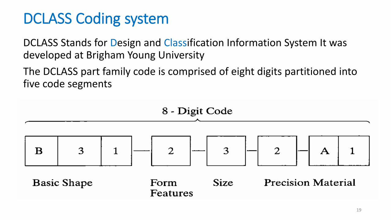
DCLASS Coding system
DCLASS Stands for Design and Classification Information System It was developed at Brigham Young University
The DCLASS part family code is comprised of eight digits partitioned into five code segments
19

Production Flow Analysis (PFA)
• Production flow analysis (PFA) is a method for identifying part families and
associated machine groupings that uses the information contained on process plans
rather than on part drawings.
• Steps involved in PFA
Data collection
Sortation of process routings
Preparation of a PFA chart and
Cluster analysis20
Production Flow Analysis (PFA)
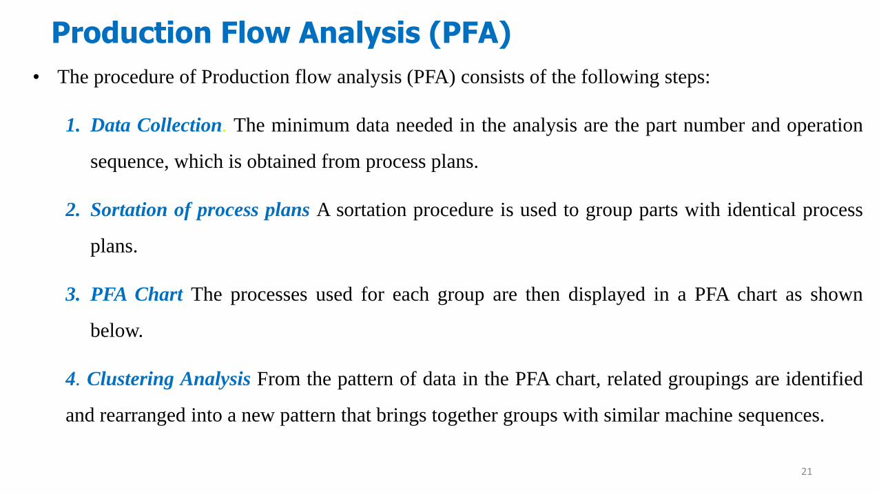
• The procedure of Production flow analysis (PFA) consists of the following steps:
1. Data Collection. The minimum data needed in the analysis are the part number and operation
sequence, which is obtained from process plans.
2. Sortation of process plans A sortation procedure is used to group parts with identical process
plans.
3. PFA Chart The processes used for each group are then displayed in a PFA chart as shown
below.
4. Clustering Analysis From the pattern of data in the PFA chart, related groupings are identified
and rearranged into a new pattern that brings together groups with similar machine sequences.
21

Part ‘Number’
Machin
e ID
1 2 3 4 5 6
1 1 1
2 1 1
3 1 1
4 1 1 1
5 1 1 1
Example #1
Consider a problem of 5 machines and 6 parts. Try to group them by using
Rank Order Clustering Algorithm.
22
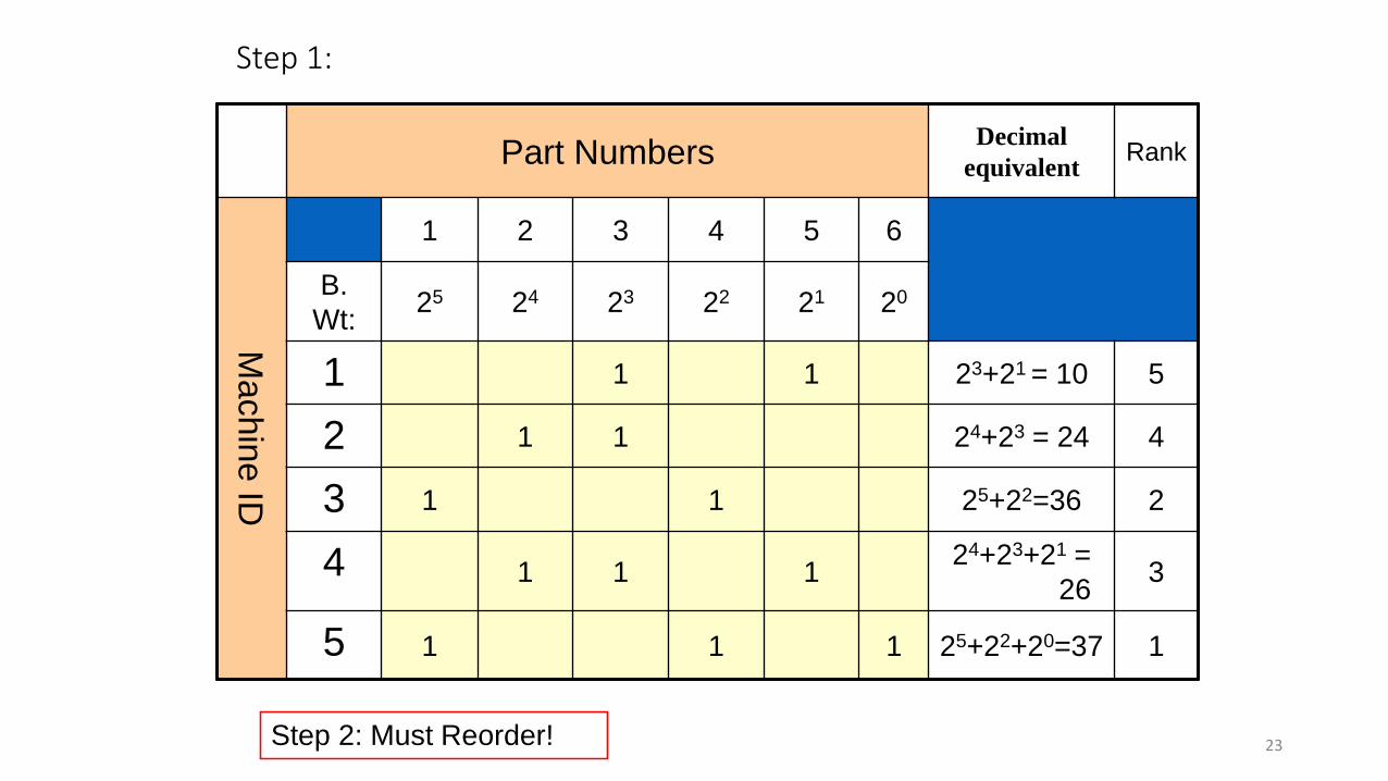
Step 1:
Part NumbersDecimal
equivalentRank
Machin
e ID
1 2 3 4 5 6
B.
Wt:25 24 23 22 21 20
1 1 1 23+21 = 10 5
2 1 1 24+23 = 24 4
3 1 1 25+22=36 2
4 1 1 124+23+21 =
263
5 1 1 1 25+22+20=37 1
Step 2: Must Reorder! 23

Step 2:
Part Number
1 2 3 4 5 6
Ma
ch
ine
ID
5 1 1 1
3 1 1
4 1 1 1
2 1 1
1 1 1
24

Step 3:
Part Number
B. WT. 1 2 3 4 5 6
Ma
ch
ine
ID
5 24 1 1 1
3 23 1 1
4 22 1 1 1
2 21 1 1
1 20 1 1
Decimal
equivalent
24+23
= 24
22+21=
6
22+21+
20=7
24+23=
24
22+20=
524=16
Rank 1 5 4 2 6 3
Step 4: Must Reorder 25
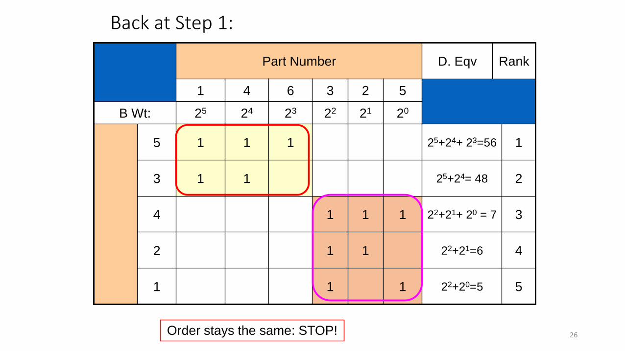
Back at Step 1:
Part Number D. Eqv Rank
1 4 6 3 2 5
B Wt: 25 24 23 22 21 20
5 1 1 1 25+24+ 23=56 1
3 1 1 25+24= 48 2
4 1 1 1 22+21+ 20 = 7 3
2 1 1 22+21=6 4
1 1 1 22+20=5 5
Order stays the same: STOP! 26
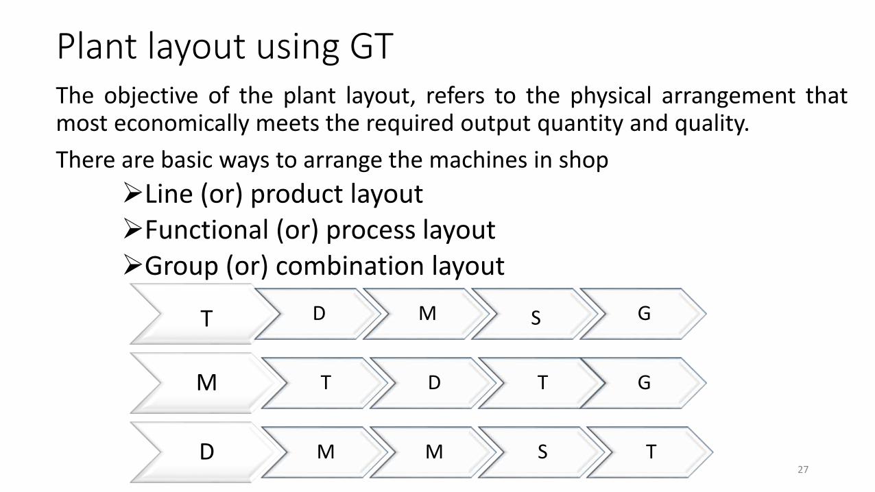
Plant layout using GTThe objective of the plant layout, refers to the physical arrangement thatmost economically meets the required output quantity and quality.
There are basic ways to arrange the machines in shop
Line (or) product layoutFunctional (or) process layoutGroup (or) combination layout
T D M S G
M T D T G
D M M S T27
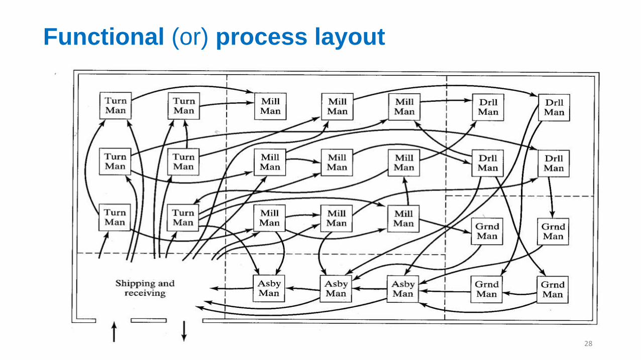
Functional (or) process layout
28
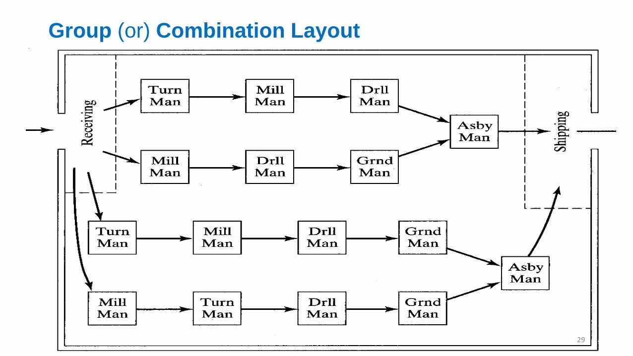
Group (or) Combination Layout
29
BENEFITS OF GT
Engineering Design
Tooling and setups
Materials and Handling
Production and Inventory control
Process planning
Management and employees
30

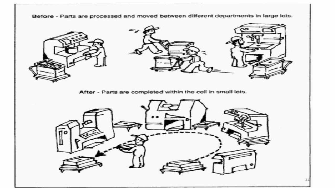
Cellular Manufacturing
Application of group technology in which dissimilar machines or processes
are aggregated into cells, each of which is dedicated to the production of a
part family or limited group of families
Typical objectives of cellular manufacturing:
To shorten manufacturing lead times
To reduce WIP
To improve quality
To simplify production scheduling
To reduce setup times31
32
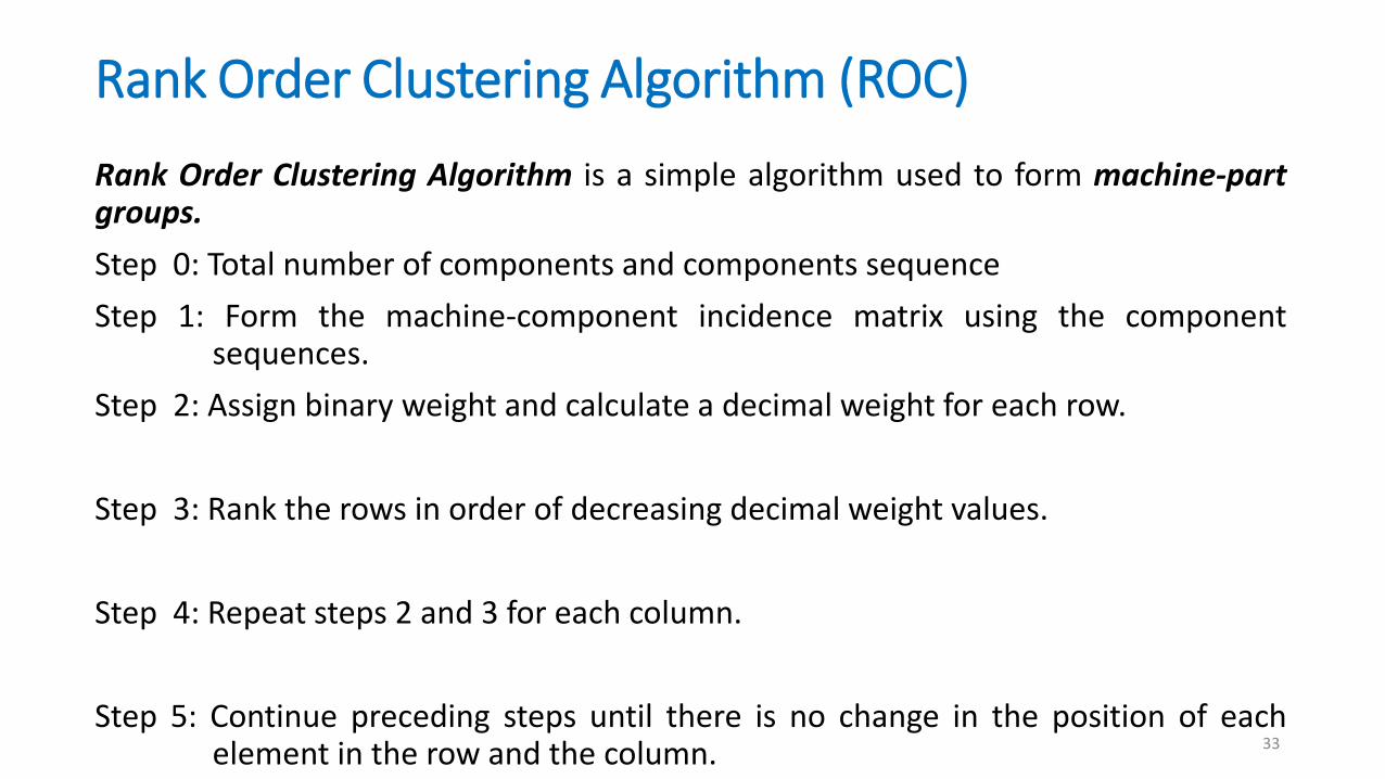
Rank Order Clustering Algorithm (ROC)
Rank Order Clustering Algorithm is a simple algorithm used to form machine-partgroups.
Step 0: Total number of components and components sequence
Step 1: Form the machine-component incidence matrix using the componentsequences.
Step 2: Assign binary weight and calculate a decimal weight for each row.
Step 3: Rank the rows in order of decreasing decimal weight values.
Step 4: Repeat steps 2 and 3 for each column.
Step 5: Continue preceding steps until there is no change in the position of eachelement in the row and the column. 33
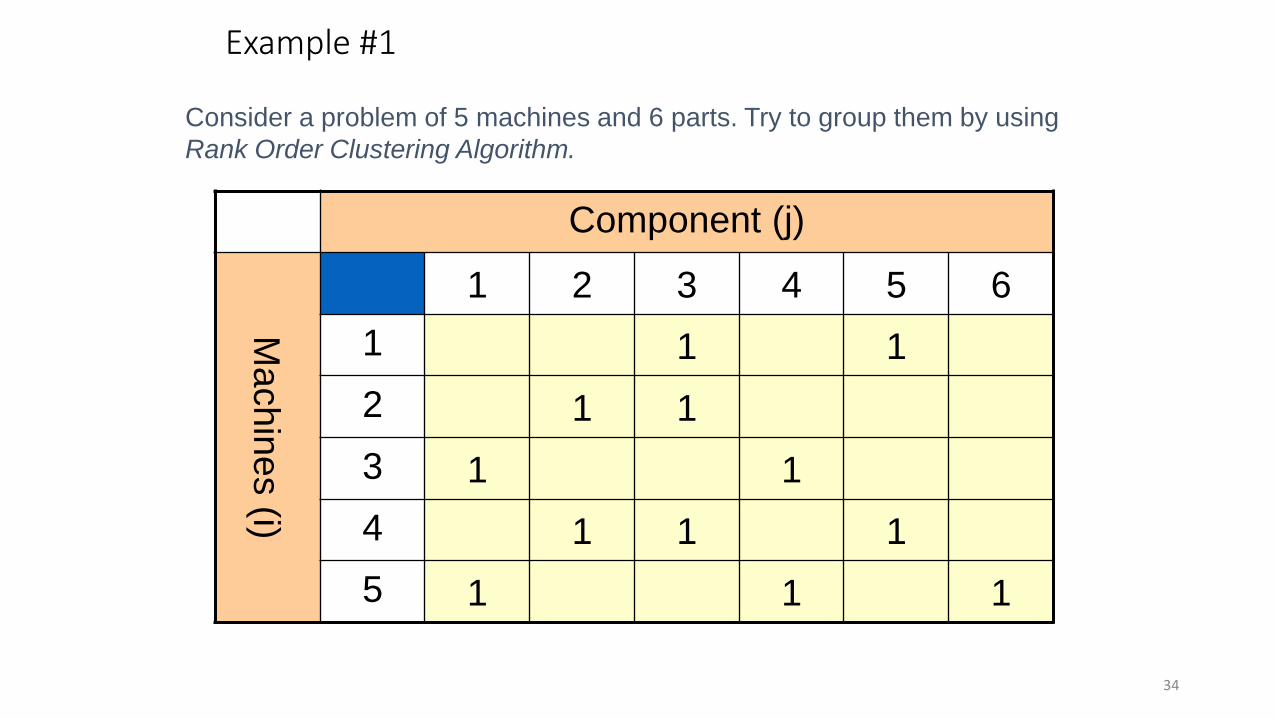
Component (j)
Machin
es (i)
1 2 3 4 5 6
1 1 1
2 1 1
3 1 1
4 1 1 1
5 1 1 1
Example #1
Consider a problem of 5 machines and 6 parts. Try to group them by using
Rank Order Clustering Algorithm.
34

Step 1:
Component (j)Decimal
equivalentRank
Machin
es (i)
1 2 3 4 5 6
B.
Wt:25 24 23 22 21 20
1 1 1 23+21 = 10 5
2 1 1 24+23 = 24 4
3 1 1 25+22=36 2
4 1 1 124+23+21 =
263
5 1 1 1 25+22+20=37 1
Step 2: Must Reorder! 35
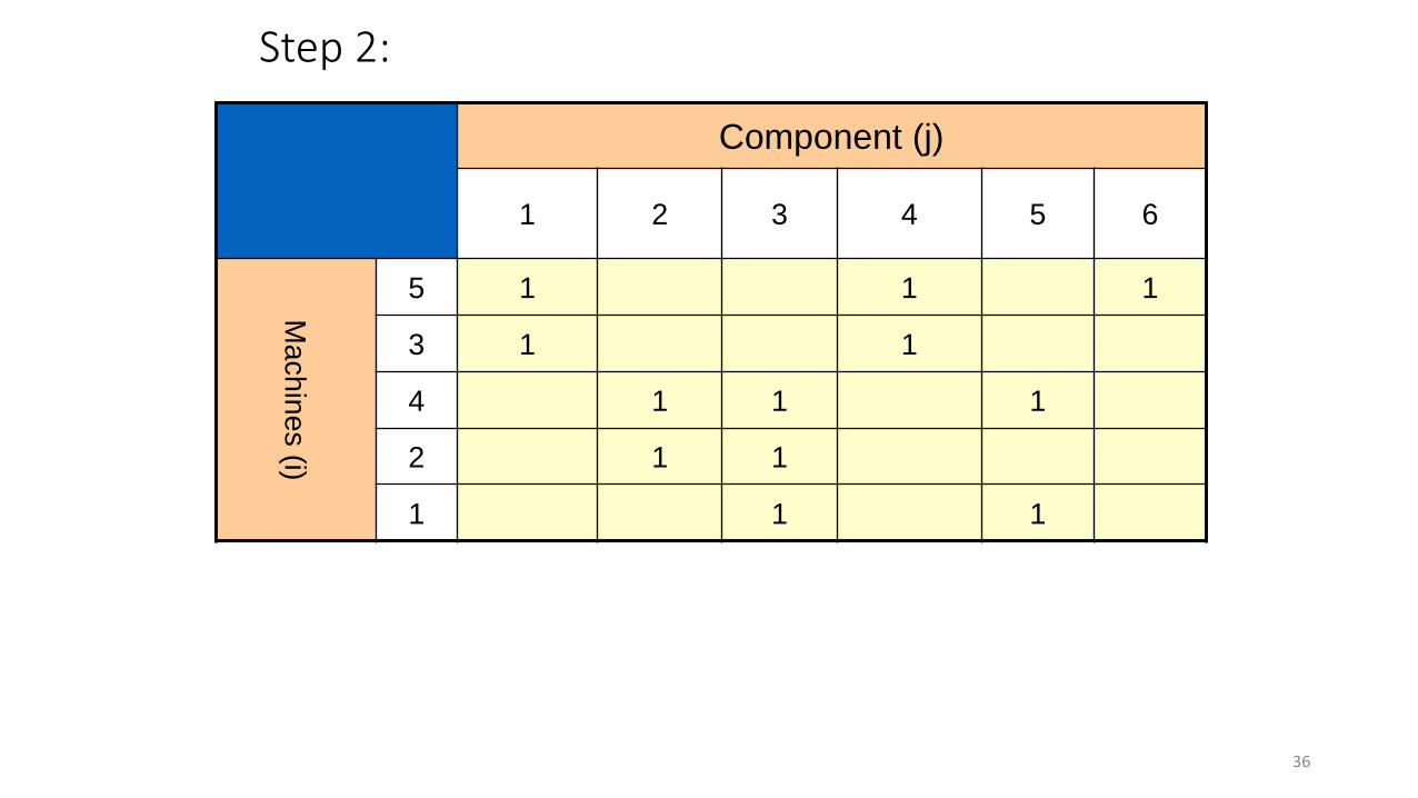
Step 2:
Component (j)
1 2 3 4 5 6
Ma
ch
ine
s (i)
5 1 1 1
3 1 1
4 1 1 1
2 1 1
1 1 1
36
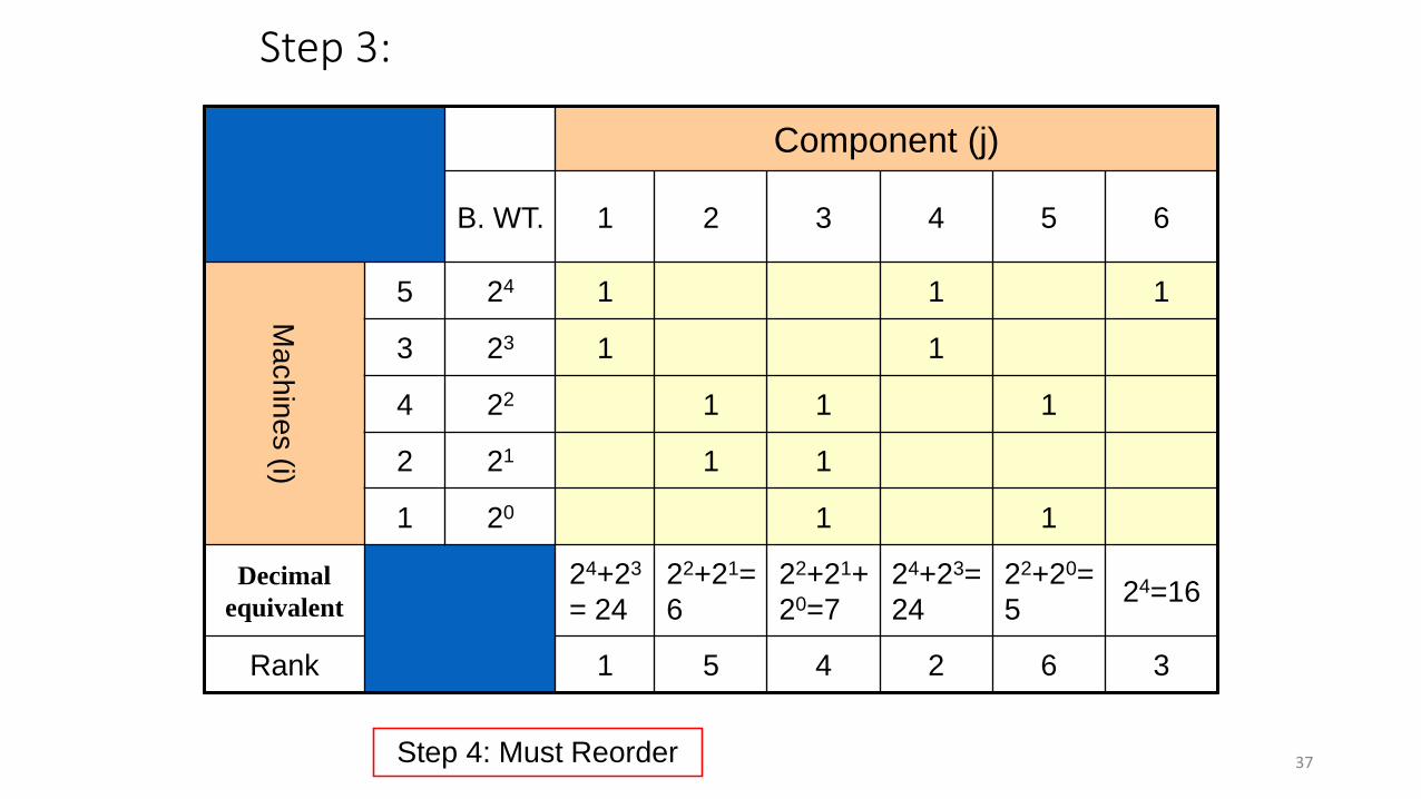
Step 3:
Component (j)
B. WT. 1 2 3 4 5 6
Ma
ch
ine
s (i)
5 24 1 1 1
3 23 1 1
4 22 1 1 1
2 21 1 1
1 20 1 1
Decimal
equivalent
24+23
= 24
22+21=
6
22+21+
20=7
24+23=
24
22+20=
524=16
Rank 1 5 4 2 6 3
Step 4: Must Reorder 37

Back at Step 1:
Component (j) D. Eqv Rank
1 4 6 3 2 5
B Wt: 25 24 23 22 21 20
Machin
es (i)
5 1 1 1 25+24+ 23=56 1
3 1 1 25+24= 48 2
4 1 1 1 22+21+ 20 = 7 3
2 1 1 22+21=6 4
1 1 1 22+20=5 5
Order stays the same: STOP! 38

Clustering Methods
• Using Process Similarity methods:
• Create Machine – Part Matrices
• Compute machine ‘pair-wise’ similarity Coefficient comparisons:
39
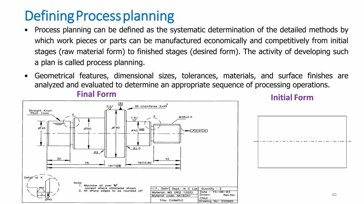
DefiningProcessplanning• Process planning can be defined as the systematic determination of the detailed methods by
which work pieces or parts can be manufactured economically and competitively from initial
stages (raw material form) to finished stages (desired form). The activity of developing such
a plan is called process planning.
Initial FormFinal Form
• Geometrical features, dimensional sizes, tolerances, materials, and surface finishes areanalyzed and evaluated to determine an appropriate sequence of processing operations.
40

Process Planning Steps
41
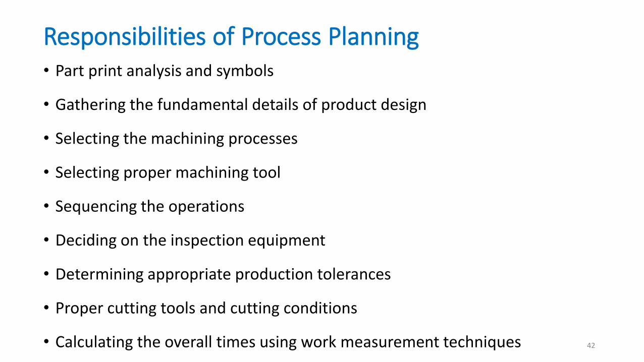
Responsibilities of Process Planning• Part print analysis and symbols
• Gathering the fundamental details of product design
• Selecting the machining processes
• Selecting proper machining tool
• Sequencing the operations
• Deciding on the inspection equipment
• Determining appropriate production tolerances
• Proper cutting tools and cutting conditions
• Calculating the overall times using work measurement techniques 42

PROCESS PLANNING ACTIVITES
ANALYSIS (part requirements)
DETERMINE (operation sequence)
SELECTION OF MACHINES (equipment)
CALCULATE (processing times)
DOCUMENT (process planning)
COMMUNICATION (mfg. engr. To shop floor) 43
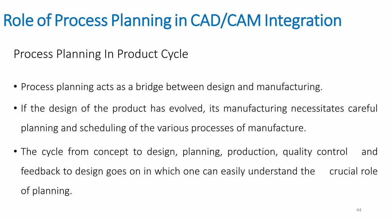
Role of Process Planning in CAD/CAM Integration
Process Planning In Product Cycle
• Process planning acts as a bridge between design and manufacturing.
• If the design of the product has evolved, its manufacturing necessitates careful
planning and scheduling of the various processes of manufacture.
• The cycle from concept to design, planning, production, quality control and
feedback to design goes on in which one can easily understand the crucial role
of planning.
44
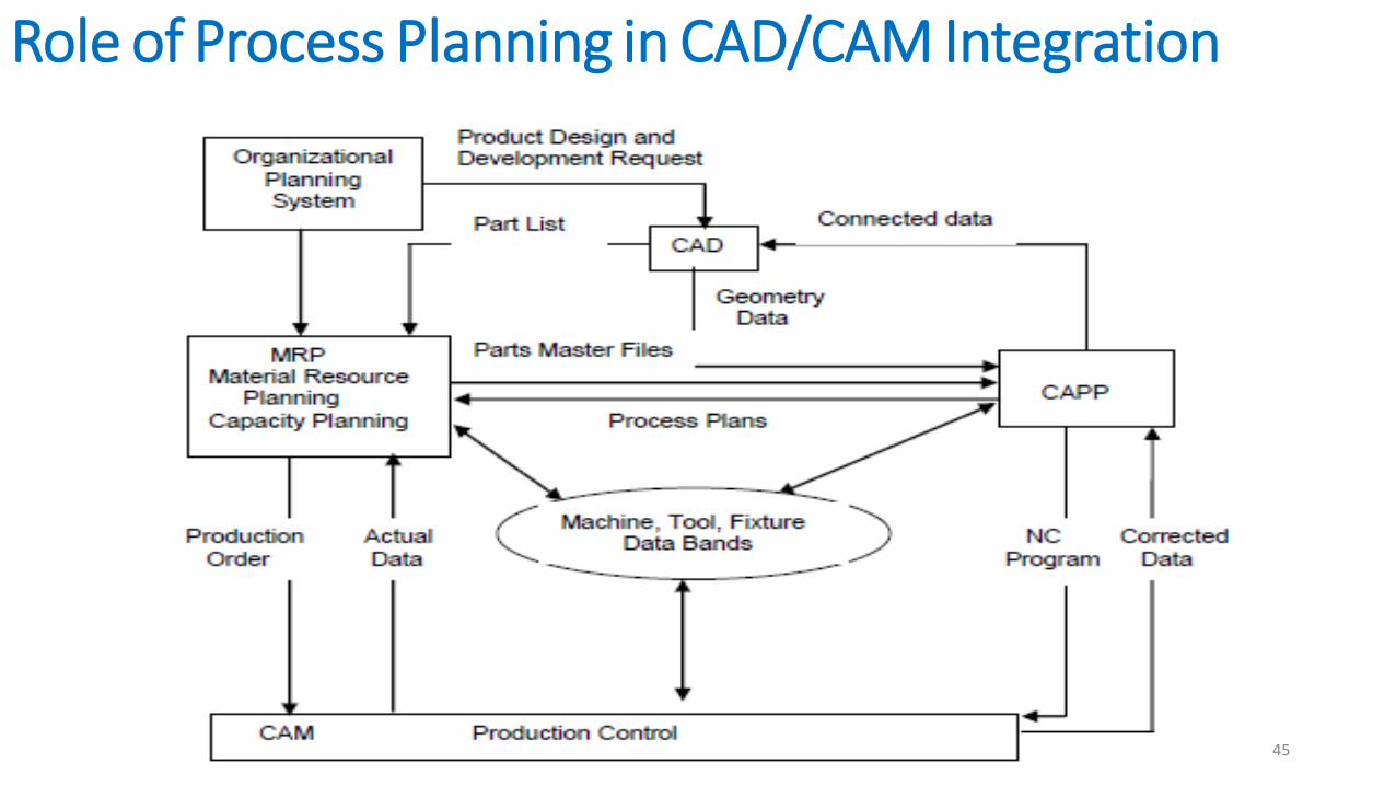
Role of Process Planning in CAD/CAM Integration
45
Manual process planning
Advantages of MPPVery much suitable for small scale company
Low investment cost
Disadvantages of MPPSkilled process planner
Very complex and time consuming job
More possibilities for human error
Increases paper work
46

Computer Aided Process Planning
• Process rationalization and standardisation
• Productivity improvement
• Product cost reduction
• Elimination of human error
• Reduction in time
• Reduced paper work
• Faster response
• Improved legibility
47
Approaches to CAPP
Types of Approaches
• Variant Approach - Computer search for existing or similar processplans of similar part families using codes, retrieves and then editaccording to new process sequence.
• Generative Approach - Computer generates new process plan everytime when a new plan is needed.
48
Data Input to CAPP
• Generally the geometric model of the part is the input for the process planningsystem.
• The input to the process planning system may be engineering drawing or CADmodel.
The other prerequisites for process planning are given below:
- Parts list
- Annual demand/batch size
- Accuracy and surface finish requirement (CAD Database)
- Equipment details (Work centre Database)
- Data on cutting fluids, tools, jigs & fixtures, gauges
- Standard stock sizes
- Machining data, data on handling and setup49

Variant or Retrieval Approaches to CAPP
Part
Description GT Code Process Plan
Retrieve/Edit
New
Process Plan
Master Plans
Database
50
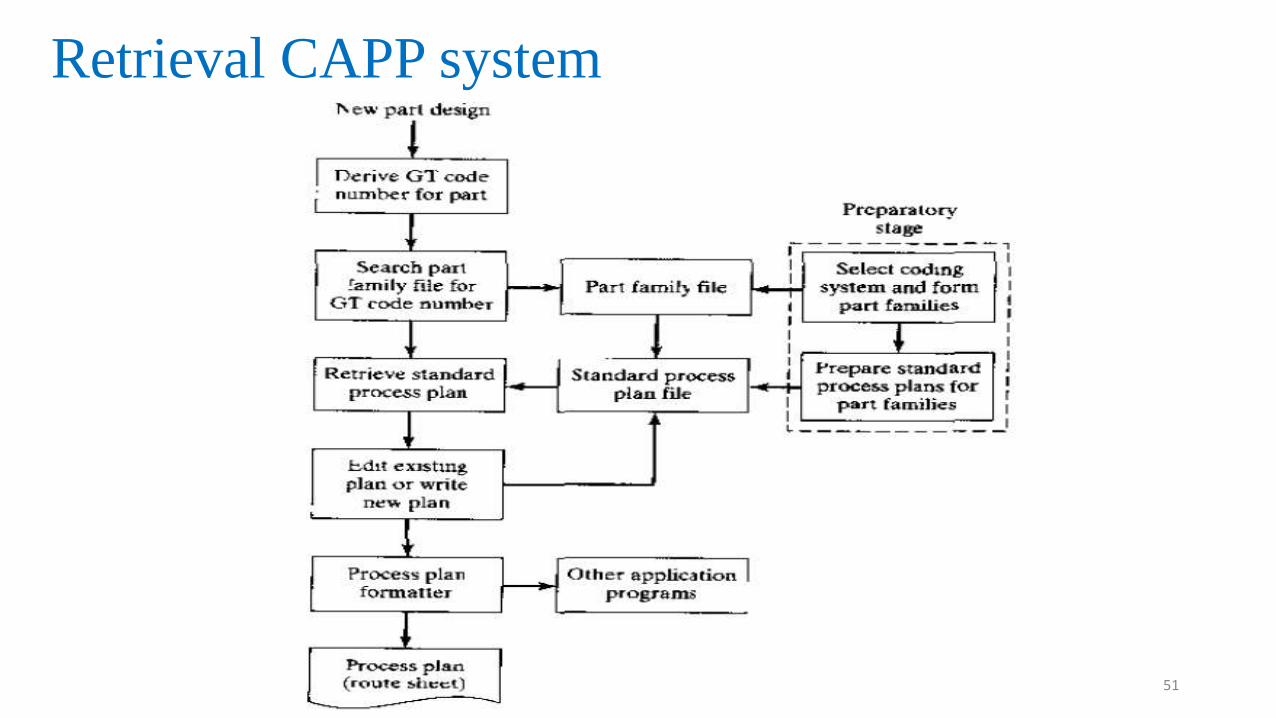
Retrieval CAPP system
51
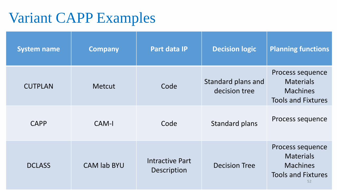
Variant CAPP Examples
System name Company Part data IP Decision logic Planning functions
CUTPLAN Metcut CodeStandard plans and
decision tree
Process sequence Materials Machines
Tools and Fixtures
CAPP CAM-I Code Standard plansProcess sequence
DCLASS CAM lab BYUIntractive Part
DescriptionDecision Tree
Process sequence Materials Machines
Tools and Fixtures52
Advantages / Disadvantages of Variant type CAPP
Advantages
• Reduction of time and labour requirement.
• Processing and evaluation of complicated activities and managerial issues are done in
an efficient manner.
• Structuring manufacturing knowledge of the process plans to company’s needs
through standardized procedures.
Disadvantages
• Difficult to maintain consistency during editing.
• Proper accommodation of various combinations of attributes such as material,
geometry, size, precision, quality, alternate processing sequence and machine loading
among many other factors are difficult.
• Quality is dependent on knowledge and skill of planner. 53
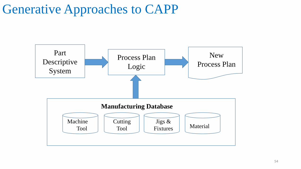
Generative Approaches to CAPP
Part
Descriptive
System
New
Process Plan Process Plan
Logic
Machine
Tool
Cutting
Tool
Jigs &
Fixtures Material
Manufacturing Database
54

Generative CAPP Examples• APPAS
• CADAM
• BYUPLAN
• GENPLAN
• PROPLAN
MERITS AND DEMERTIS
• New components can be planned easily as existing components
• Drawbacks is complex and very difficult to develop 55

Computer Managed Process Planning (CMPP)
It is a generative system capable of automatically making process
decisions.
An extensive interactive capability is provided which permits the use to
examine and modify a process plan as it is developed.
56
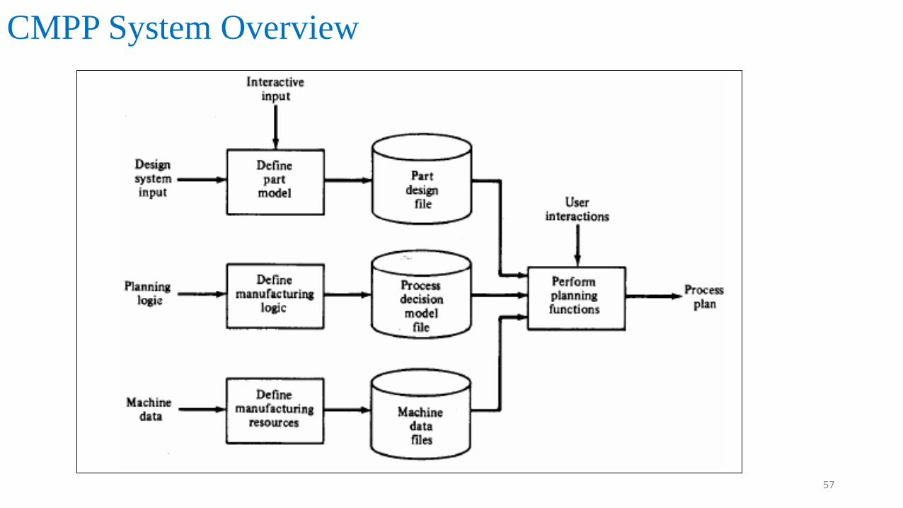
CMPP System Overview
57
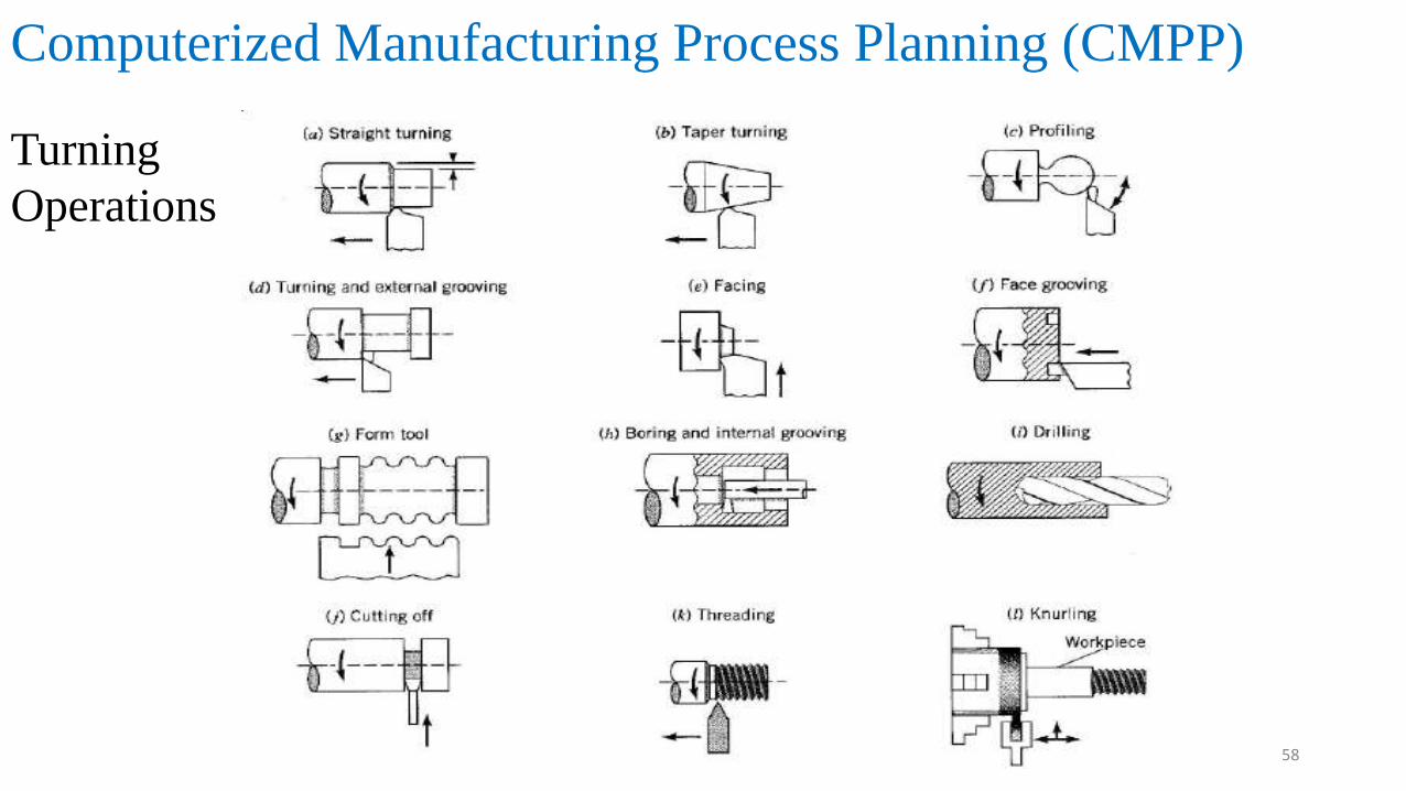
Computerized Manufacturing Process Planning (CMPP)
Turning
Operations
58
IMPORTANT QUESTIONS
1. Define Group Technology and its role in CAD/CAM Integration.
2. What is Part Families Classification And Coding?
3. Explain – DCLASS / MCLASS with suitable examples.
4. Explain OPTIZ Coding Systems with illustrations.
5. Explain facility design using G.T and its benefits of GT.
6. Define Cellular Manufacturing.
7. What is Process Planning and explain its role Of Process Planning in CAD/CAM Integration.
8. What are the types/approaches to CAPP? Explain Variant or Retrieval Approach / Generative
Approaches
9. Compare and contrast CAPP And CMPP Systems.59