
UNIT III REYNOLDS EXPERIMENT - rgcetpdy.ac.in YEAR/MECHANICS OF... · From this experiment,...
22
UNIT III REYNOLDS EXPERIMENT The velocity at which the flow changes from the laminar to turbulent for the case of given fluid at a given temperature and given pipe is known as critical velocity. This critical velocity only determines that the flow is either laminar or turbulent. Prof. Osborne Reynolds was first to find that the value of critical velocity is governed by the relationship between the inertia force and viscous force. He derived a ratio of the lie two forces and obtained a dimensionless number called Reynolds number. Reynolds number, Re = I୬୰୲ia ୭୰ୡ Viୱୡ୭୳ୱ ୭୰ୡ Inertia force = Mass x Acceleration = ρ x Volume x acceleration = ρ x L 3 x (LT -2 ) = ρ 2 L 2 V 2 Viscous force = Shear stress x Area = μ ( δV δ୷ ) x L 2 = μ V L Reynolds number, Re = ρ 2 L 2 V 2 / μ V L = µ = [ µ ఘ = ] Where, ρ = Density of the fluid V = Mean velocity of flow L = Characteristic linear dimension = Diameter of the pipe (D) μ = Viscosity of the fluid. v= Kinematic viscosity of the fluid. The existence of two types of flow (i.e, Laminar and Turbulent flow) was demonstrated by Prof. Reynolds with the help of the following simple experiment. The apparatus used for the experiment is shown in Figure. The apparatus consists of (i) A water tank (ii) An arrangement to inject a fine filament of dye into the bell mouthed entrance of a glass tube through which water flows and (iii) A valve to control the flow through the tube. The water was made to flow from the tank through the glass tube into the atmosphere and the velocity of flow was varied by adjusting the regulating and the velocity of flow was varied by adjusting the regulating valve. A fine filament of dye was introduced into the glass tube near the entrance of the tube. It was concluded that when the flow velocity was low, the dye appeared as a straight line parallel to the tube axis characterizing laminar flow. 1
Transcript of UNIT III REYNOLDS EXPERIMENT - rgcetpdy.ac.in YEAR/MECHANICS OF... · From this experiment,...

UNIT III
REYNOLDS EXPERIMENT
The velocity at which the flow changes from the laminar to turbulent for the case of given fluid at a given
temperature and given pipe is known as critical velocity.
This critical velocity only determines that the flow is either laminar or turbulent. Prof. Osborne Reynolds
was first to find that the value of critical velocity is governed by the relationship between the inertia force
and viscous force.
He derived a ratio of the lie two forces and obtained a dimensionless number called Reynolds number.
Reynolds number, Re = I ia Vi
Inertia force = Mass x Acceleration
= ρ x Volume x acceleration
= ρ x L3 x (LT-2 )
= ρ2 L2 V2
Viscous force = Shear stress x Area
= µ (δVδ ) x L2
= µ V L
Reynolds number, Re = ρ2 L2 V2 / µ V L
= � �µ =
�� [ µ = � ]
Where, ρ = Density of the fluid
V = Mean velocity of flow
L = Characteristic linear dimension = Diameter of the pipe (D)
µ = Viscosity of the fluid.
v= Kinematic viscosity of the fluid.
The existence of two types of flow (i.e, Laminar and Turbulent flow) was demonstrated by Prof.
Reynolds with the help of the following simple experiment. The apparatus used for the experiment is
shown in Figure.
The apparatus consists of (i) A water tank (ii) An arrangement to inject a fine filament of dye into the
bell mouthed entrance of a glass tube through which water flows and (iii) A valve to control the flow
through the tube.
The water was made to flow from the tank through the glass tube into the atmosphere and the velocity
of flow was varied by adjusting the regulating and the velocity of flow was varied by adjusting the
regulating valve.
A fine filament of dye was introduced into the glass tube near the entrance of the tube. It was concluded
that when the flow velocity was low, the dye appeared as a straight line parallel to the tube axis
characterizing laminar flow.
1

As the valve was further opened and greater velocities attained, the dye filament became wavy, this
state is called "Transition state". With further increase in the velocity, the fluctuations in the filament of
dye became more intense and finally diffusing into the flowing water. Ii shows the turbulent flow.
From this experiment, Reynolds found that the occurrence of a laminar and turbulent flow was governed
by the relative magnitudes of the inertia and the viscous forces.
At low velocities, viscous forces become predominant and therefore, flow is largely viscous in character.
At higher velocities, the inertia forces have predominance over the viscous force.
After carrying out a series of experiments, Reynolds found that if Reynolds number for a particular flow
is less than 2000, the flow is a laminar flow.
If the Reynolds number is between 2000 and 4000, it is neither laminar flow nor turbulent flow (i.e.,
Transition state). But, if the Reynolds number exceeds 4000, the flow is a turbulent flow. Experimentally,
the value of the lower critical Reynolds number has been found to be approximately 2000. So, simply
Re < 2000 ---> Laminar flow.
2000 < Re < 4000 ---> Transition flow.
Re > 4000 ---> Turbulent flow.
----------------------------------------------------------------------------------------------------------------------------
FRICTIONAL LOSS IN PIPE FLOW
When a liquid is flowing through a pipe, the velocity of the liquid layer adjacent to the pipe wall is zero.
The velocity of liquid goes on increasing from the wall and thus velocity gradient and hence shear
stresses are produced in the whole liquid due to viscosity.
This viscous action causes loss of energy which is usually known as frictional loss. On the basis of his
experiments, William Froude gave the following laws of fluid fraction for turbulent flow.
2

The frictional resistance for turbulent flow is:
proportional to Vn, where « varies from 1.5 to 2.0
proportional to the density of fluid
proportional to the area of surface in contact
independent of pressure
dependent on the nature of the surface in contact.
----------------------------------------------------------------------------------------------------------------------------
METHODS OF DETERMINATION OF CO-EFFICIENT OF VISCOSITY
The following are the experimental methods of determining the co-efficient of viscosity of a liquid:
1. Capillary tube method.
2. Falling sphere resistance method,
3. By rotating cylinder method, and
4. Orifice type viscometer.
The apparatus used for determining the viscosity of a liquid is called viscometer.
----------------------------------------------------------------------------------------------------------------------------
CAPILLARY TUBE METHOD
In capillary tube method, the viscosity of a liquid is calculated by measuring the pressure difference for
a given length of the capillary tube. The Hagen Poiseuille law is used for calculating viscosity Fig.
Shows the capillary lube viscometer.
The liquid whose viscosity is to be determined is filled in a constant head tank. The liquid is maintained
at constant temperature and is allowed to pass through the capillary tube from the constant head tank.
Then, the liquid is collected in a measuring tank for a given time.
Then the rate of liquid collected in the tank per second is determined. The pressure head '/r is measured
at a point far away from the tank as shown in Fig.
Then h = Difference of pressure head for length L.
The pressure at outlet is atmospheric.
Let D = Diameter of capillary tube,
L = Length of tube for which difference of pressure head is known,
ρ = Density of fluid.
µ = � .�
Measurement of D should be done very accurately.
----------------------------------------------------------------------------------------------------------------------------
3

FALLING SPHERE RESISTANCE METHOD
Theory. This method is based on Stoke's law, according to which the drag force, F on a small sphere
moving with a constant velocity, U through a viscous fluid of viscosity, µ for viscous conditions is given
by
F= 3 π µ Ud
where d = diameter of sphere
U = velocity of sphere
When the sphere attains a constant velocity U, the drag force is the difference between the weight of
sphere and buoyant force acting on it.
Let L = distance travelled by sphere in viscous fluid
t = time taken by sphere to cover distance l �� = density of sphere � = density of fluid
W = weight of sphere
and FB = buoyant force acting on sphere.
Fig. Falling sphere resistance
µ = �� [ �� ]
where, �� = density of liquid
Hence in equation , the values of d, U, ρs and ρf are known and hence the viscosity of liquid can be
determined.
Method: Thus this method consists of a tall vertical transparent cylindrical tank, which is filled with the
liquid whose viscosity is to be determined.
This tank is surrounded by another transparent tank to keep the temperature of the liquid in the
cylindrical tank to be constant.
A spherical ball of small diameter‘d’ is placed on the surface of liquid. Provision is made to release this
ball. After a short distance of travel, the ball attains a constant velocity.
The time to travel a known vertical distance between two fixed marks on the cylindrical tank is noted to
calculate the constant velocity V of the ball. Then with the known values of d, ρs, ρf, the viscosity µ of
the fluid is calculated by using equation.
----------------------------------------------------------------------------------------------------------------------------
4

ROTATING CYLINDER METHOD
This method consists of two concentric cylinders of radii R1 and R2 as shown in Fig. The narrow space
between the two cylinders is filled with the liquid whose viscosity is to be determined.
The inner cylinder is held stationary by means of a torsional spring while outer cylinder is rotated at
constant angular speed w.
The torque T acting on the inner cylinder is measured by the torsional spring. The torque on the inner
cylinder must be equal and opposite to the torque applied on the outer cylinder.
The torque applied on the outer cylinder is due to viscous resistance provided by liquid in the annular
space and at the bottom of the inner cylinder.
µ = − ℎ � � [ � ℎ + − ]
where,
T = torque measured by the strain of the torsional spring
R1 and R2 = radii of inner and outer cylinder
h = clearance at the bottom of cylinders
H = height of liquid in annular space
µ = co-efficient of viscosity to be determined
Hence, the value of µ can be calculated from equation.
----------------------------------------------------------------------------------------------------------------------------
ORIFICE TYPE VISCOMETER
In this method, the time taken by a certain quantity of the liquid whose viscosity is to be determined, to
flow through a short capillary tube is noted down.
The co-efficient of viscosity is then obtained by comparing with the co-efficient of viscosity of a liquid
whose viscosity is known or by the use conversion factors.
Viscometers such as Saybolt. Redwood or Engler are usually used. The principle for all the three
viscometer is same. In the United Kingdom, Redwood viscometer is used while in U.S.A.. Saybolt
viscometer is commonly used.
Fig. shows that Say bolt viscometer, which consists of a tank at the bottom of which a short capillary
tube is fitted.
5

In this tank the liquid whose viscosity is to be determined is filled. This tank is surrounded by another
tank, called constant temperature bath.
The liquid is allowed to flow through capillary lube at a standard temperature. The time taken by 60 c.c.
of the liquid lo flow through the capillary tube is noted down. The initial height of liquid in the tank is
previously adjusted to a standard height. From the time measurement, the kinematic viscosity of liquid
is known from the relation,
Saybolt viscometer
v = A t - �
where, A = 0.24 , B = 190
t = time noted in seconds
v =vkinematic viscosity in stokes
----------------------------------------------------------------------------------------------------------------------------
6

FLOW THROUGH A PIPE
Here the turbulent flow of fluids through pipes running full will be considered. It the pipes are partially
full as in the case of sewer lines, the pressure inside the pipe is same and equal to atmospheric
pressure.
Then the flow of fluid in the pipe is not under pressure. This case will be taken in the chapter of flow of
water through open channels. Here we will consider flow of fluids through pipes under pressure only.
LOSS OF ENERGY IN PIPES
When a fluid is flowing through a pipe, the fluid experiences some resistance due to which some of the
energy of fluid is lost. This loss of energy is classified as:
ENERGY LOSSES
1. Major Energy Losses.
This is due to friction and it is calculated by the following formulae:
(a) Darcy-Weisbach Formula
(b) Chezy's Formula
2. Minor Energy Losses
This is due to
(а) Sudden expansion of pipe
(b) Sudden contraction of pipe
(c) Bend in pipe
(d) Pipe fittings etc.
(e) An obstruction in pipe.
----------------------------------------------------------------------------------------------------------------------------
MINOR ENERGY (HEAD) LOSSES
The loss of head or energy due to friction in a pipe is known as major loss while the loss of energy due
to change of velocity of die following fluid in magnitude or direction is called minor loss of energy. The
minor loss of energy (or head) includes the following cases:
Loss of head due to sudden enlargement
Loss of head due to sudden contraction
Loss of head at the entrance of a pipe
Loss of head at the exit of a pipe
Loss of head due to an obstruction in a pipe
Loss of head due to bend in the pipe
Loss of head in various pipe fittings
In case of long pipe the above losses me small as compared with the loss of head due to friction
and hence they are called minor losses and even may he neglected without serious error. But in case
of a short pipe, these losses are comparable with the loss of head due to friction.
----------------------------------------------------------------------------------------------------------------------------
7

----------------------------------------------------------------------------------------------------------------------------
8

----------------------------------------------------------------------------------------------------------------------------
9

10

----------------------------------------------------------------------------------------------------------------------------
11

---------------------------------------------------------------------------------------------------------------------------
12

MINOR ENERGY (HEAD) LOSSES
The loss of head or energy due to friction in a pipe is known as major loss while the loss of energy
due to change of velocity of the following fluid in magnitude or direction is called minor loss of energy.
The minor loss of energy (or head) includes the following cases:
1. Loss of head due to sudden enlargement
2. Loss of head due to sudden contraction
3. Loss of head at the entrance of a pipe
4. Loss of head at the exit of a pipe
5. Loss of head due to an obstruction in a pipe
6. Loss of head due to bend in the pipe
7. Loss of head in various pipe fittings.
In case of long pipe the above losses are small as compared with the loss of head due to friction and
hence they are called minor losses and even may be neglected without serious error. But in case of a
short pipe, these losses are comparable with the loss of head due to friction.
---------------------------------------------------------------------------------------------------------------------------
LOSS OF HEAD DUE TO SUDDEN ENLARGEMENT.
Consider a liquid flowing through a pipe which has sudden enlargement as shown in Fig. Consider
two section (1)-(1) and (2)-(2) before and after the enlargement.
Let p1 = pressure intensity at section 1.1
V1 = velocity of flow at section 1.1
A1 = area of pipe at section 1.1
P2 , V2 and A2 = corresponding values at section 2.2.
Due to sudden change of diameter of the pipe from D1 to D2 , the liquid flowing from the smaller pipe
is not able to follow the abrupt change of the boundary. Thus the flow separates from the boundary
and turbulent eddies are formed as sown in Fig. 11.1. The loss of head (or energy) takes place due to
the formation of theses eddies.
Let p1 = pressure intensity of the liquid eddies on the area (A2 - A1)
13

he = loss of head due to sudden enlargement
Applying Bernoulli’s equation at section 1.1 and 2.2
+ �
+ � = + �
+ � + loss of head due to sudden enlargement
But � = � as pipe is horizontal
+ �
= + �
+ ℎ
or ℎ = − + � − � …………(i)
Consider the control volume of liquid between section 1-1 and 2-2. Then the force acting on
the liquid in the control volume in the direction of flow is given by
�� = � A1 + p( A2 - A1) - � A2
But experimentally it is found that p= p1
�� = � A1 + p1( A2 - A1) - � A2 =� A2 + � A2
Momentum of liquid/sec at section 1-1 = mass x velocity
= �A1 V1 x V1 = �A1�
Momentum of liquid/sec at section 2-2 = �A2 V2 x V2 = �A2�
Change of momentum/sec = �A2 � − �A1�
But from continuity equation, we have
A1 V1 = A2 V2 or A1 = � ��
Change of momentum/sec = �A2 � − � x � �� x � = �A2 � − �A2 V1V2
= �A2 [� −V1V2]
Now net force acting on the control volume in the direction of flow must be equal to the rate of change
of momentum or change of momentum per second. Hence equating (ii) and (iii)
(� – � ) A2 = �A2 [� − V1V2]
or � – �
= � − V1V2
Dividing by g on both sides, we have � – �
= � −V V
or �
- �
= � −V V
Substituting the value of � − � in equation (i), we get
ℎ = � −V V
+ �
- �
= � − V V +� −�
= � +� − V V
= � −�
14
ℎ = � −�
……………(11.5)
---------------------------------------------------------------------------------------------------------------------------
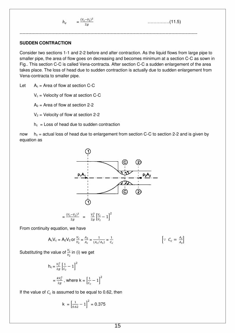
SUDDEN CONTRACTION
Consider two sections 1-1 and 2-2 before and after contraction. As the liquid flows from large pipe to
smaller pipe, the area of flow goes on decreasing and becomes minimum at a section C-C as sown in
Fig.. This section C-C is called Vena-contracta. After section C-C a sudden enlargement of the area
takes place. The loss of head due to sudden contraction is actually due to sudden enlargement from
Vena-contracta to smaller pipe.
Let Ac = Area of flow at section C-C
Vc = Velocity of flow at section C-C
A2 = Area of flow at section 2-2
V2 = Velocity of flow at section 2-2
hc = Loss of head due to sudden contraction
now hc = actual loss of head due to enlargement from section C-C to section 2-2 and is given by
equation as
= � −�
= �
[�� − ]
From continuity equation, we have
AcVc = A2V2 or �� =
�� = � �⁄ = [∵ = �� ] Substituting the value of
�� in (i) we get
hc = �
[ − ]
= ��
, where k = [ − ]
If the value of is assumed to be equal to 0.62, then
k = [ . − ] = 0.375
15

Then hc becomes as hc = ��
= 0.375 �
If the value of Cc is not given then the head loss due to contraction is taken as
= 0.5 �
or hc = 0.5 �
---------------------------------------------------------------------------------------------------------------------------------------
Find the loss of head when a pipe of diameter 200 mm is suddenly enlarged to a diameter of
400 mm. The rate of flow of water through the pipe is 250 litres/s.
Solution. Given:
Dia. Of smaller pipe, D1 = 200 mm = 0.20 m
Area, A1 = = (.2)2 = 0.03141 m2
Dia. Of large pipe, D2 = �� = 0.4m
Area, A2 = x (0.4)2 = 0.12564 m2
Discharge, Q = 250 litres/s = 0.25 m3/s
Velocity, V1= � = .. = 7.96 m/s
Velocity, V2= � = .. = 1.99 m/s
Loss of head due to enlargement is given by equation (11.5) as
he= � −�
= . − . = 1.816 m of water.
---------------------------------------------------------------------------------------------------------------------------------------
At a sudden enlargement of a water main from 240 mm to 480 mm diameter, the hydraulic
gradient rises by 10 mm. Estimate the rate of flow.
Solution. Given:
Dia. Of smaller pipe, D1 = 240 mm = 0.24 m
Area, A1 = = (.24)2
Dia. Of large pipe, D2 = �� = 0.48 m
Area, A2 = x (0.48)2
Rise of hydraulic gradient*, i.e., [� + � ] - [� + � ] = 10 mm = = m
Let the rate of flow = Q
Applying Bernoulli’s equation to both section, i.e., smaller pipe section, and large pipe section
� + � + � =
� + � + � + Head loss due to enlargement
16

But head loss due to enlargement,
he= � −�
From continuity equation, we have � � = � �
� = � �� =
� V� = x V2 = .. x V2 = 22 x V2 = 4V2
Substituting this value in (ii), we get
he= � −�
= �
= �
Now substituting the value of he and V1in equation (i),
� + � + � =
� + � + � +
�
�
- �
- �
= [� + � ] - [� + � ] But hydraulic gradient rise = [� + � ] - [� + � ] =
�
- �
- �
= or �
=
V2 = √ . = 0.1808 = 0.181 m/s.
Discharge, Q = A2 x V2
= x V2 = (.48)2 x .181
= 0.03275 m3/s.
= 32.75 litres/s.
---------------------------------------------------------------------------------------------------------------------------------------
FLOW THROUGH PIPES IN SERIES OR FLOW THROUGH COMPOUND PIPES
Pipes in series or compound pipes are defined as the pipes of different lengths and different
diameters connected end to end (in series) to from a pipe line as shown in Fig. 11.16.
Let L1, L2, L3 = length of pipes 1, 2 and 3 respectively
d1, d2, d3 = diameter of pipes 1, 2 and 3 respectively
V1, V2, V3 = velocity of flow through pipes 1,2,3
f1, f2, f3 = co-efficient of frictions for pipes 1,2,3
H = difference of water level in the two tanks
The discharge passing through each pipe is same.
Q = A1 V1 = A2 V2 = A2 V3
17

The difference in liquid surface levels is equal to the sum of the total head loss in the pipes.
H = . �
+ � � +
. � +
� � + � −�
+ � � +
� ………….(11.12)
If minor losses are neglected, then above equation becomes as
H = � � +
� � + � � ………….(11.13)
If the co-efficient of friction is same for all pipes
i.e., f1 = f2 = f3 = f then equation (11.13) becomes as
H = � � +
� � + � �
= [� � + � � + � � ] ………….(11.14)
---------------------------------------------------------------------------------------------------------------------------------------
The difference in water surface levels in two tanks, which are connected by three pipes in series
of lengths 300 m , 170 m and 210 m and of diameters 300 mm , 200 mm and 400 mm respectively,
is 12 m. Determine the rate of flow of water if co-efficient of friction are .005 , .0052 and .0048
respectively, considering: (i) minor losses also (ii) neglecting minor losses.
Solution. Given:
Difference of water level, H = 12 m
Length of pipe 1, L1 = 300 m and dia., d1 = 300 mm = 0.3 m
Length of pipe 2, L2 = 170 m and dia., d2 = 200 mm = 0.2 m
Length of pipe 3, L3 = 210 m and dia., d3 = 400 mm = 0.4 m
Also, f1 = .005 , f2 = .0052 and f3 = .0048
(i) Considering Minor Losses. Let V1 , V2 and V3 are the velocities in the 1st , 2nd and 3rd pipe
respectively,
From continuity, we have A1V1 = A2V2 = A3V3
V2 = � ��
� � V1 = V1 =
.. x V1 = 2.25 V1
and V2 = � �� =
V1 = .. x V1 = 0.5625 V1
Now using equation (11.12), we have
18

H = . �
+ � � +
. � +
� � + � −�
+ � � +
�
Substituting V2 and V3 12.0 = . �
+ . �. +
. + . � + 4x0.0052x170 x
. �
+ . � −. �
+ . �. +
. �
or 12.0 = �
[0.5+20.0+2.53+89.505+2.847+3.189+0.316]
= �
[118.887]
V1 = √ + + .. = 1.407 m/s
Rate of flow, Q = Area x Velocity = A1 x V1
= � x V1 = (.3)2 x 1.407 = 0.09945 m3/s.
= 99.45 litres/s.
(ii) Neglecting Minor Losses. Using equation (11.13), we have
H = � � +
� � + � �
or 12.0 = �
[ . . + . .. + . .. ] =
� [20.0 + 89.505+3.189] =
� x 112.694
V1 = √ . .. = 1.445 m/s
Discharge, Q = V1 x A1= 1.445 x (.3)2 = 0.1021 m3/s = 102.1 litres/s.
---------------------------------------------------------------------------------------------------------------------------------------
Three pipes of 400mm and 300 mm diameters have lengths of 400 m, 200 m and 300 m
respectively. They are connected in series to make a compound pipe. The ends of this
compound pipe are connected with two tanks whose difference of water levels is 16 m. If co-
efficient of friction for these pipes is same and equal to 0.005, determine the discharge through
the compound pipe neglecting first the minor losses and then including them.
Solution. Given:
Difference of water levels, H = 16 m
Length and dia. of pipe 1, L1 = 400 m and , d1 = 400 mm = 0.4 m
Length and dia. of pipe 2, L2 = 200 m and d2 = 200 mm = 0.2 m
Length and dia. of pipe 3, L3 = 300 m and d3 = 300 mm = 0.3 m
Also, f1 = f2 = f3 = 0.005
(i) Discharge through the compound pipe first neglecting minor losses.
Let V1 , V2 and V3 are the velocities in the 1st , 2nd and 3rd pipe respectively,
From continuity, we have A1V1 = A2V2 = A3V3
19

V2 = � ��
� � x V1 = V1 =
.. x V1 = 4 V1
and V2 = � �� =
�� x V1 = V1
.. x V1 = 1.77V1
Now using equation (11.13) we have
H = � � +
� � + � �
or 16 = . �. . +
. �. . + . . . x . �
= � . [ . . + . . + . . . ]
16 = � . (20+320+63.14) =
� . x 403.14
V1 = √ � � .. = 0.882 m/s
Discharge, Q = V1 x A1= (0.4)2 x 0.882 = 0.1108 m3/s.
(ii) Discharge through the compound pipe considering minor losses also.
Minor losses are:
(a) At inlet, hi = . �
(b) Between 1st pipe and 2nd pipe, due to contraction,
Hc = . �
= . �
(∵ � = � )
= . �
= 8 x �
(c) Between 2nd pipe and 3rd pipe, due to sudden enlargement,
he = � −� =
� − . � (∵ � = . � )
= (2.23)2 x �
= 4.973 �
(d) At the outlet of 3rd pipe, ho = �
= . �
= 1.772 x �
= 3.1329 �
The major losses are = � � +
� � + � �
= . �. . +
. �. . + . . � . .
= . � � � .
sum of minor losses and major losses
= [ . � + � � + . � + . � ] + 403.14 �
= 419.746 �
20

But total loss must be equal to H (or 16m)
419.746 x �
=16 V1 = √ .. = 0.864 m/s
Discharge, Q = A1 x V1= (0.4)2 x 0.864 = 0.1085 m3/s.
---------------------------------------------------------------------------------------------------------------------------
EQUIVALENT PIPE
This is defined as the pipe of uniform diameter having loss of head and discharge equal to the
loss of head and discharge of a compound pipe consisting of several pipes of different lengths and
diameters. The uniform diameter of the equivalent pipe is called equivalent size of the pipe. The length
of equivalent pipe is equal to sum of lengths of the compound pipe consisting of different pipes.
Let L1 = length of pipe 1 and d1 = diameter of pipe 1
L2 = length of pipe 2 and d2 = diameter of pipe 2
L3 = length of pipe 3 and d3 = diameter of pipe 3
H = total head loss
L = length of equivalent pipe
d = diameter of the equivalent pipe
Then L = L1 + L2 + L3
Total head loss in the compound pipe, neglecting minor losses
H = � � +
� � + � �
Assuming f1 = f2 = f3 = f
Discharge, Q = A1V1 = A2V2 = A3V3 = � � = � � = � �
V1 = , V2 = , V3 =
Substituting these values in equation (11.14A), we have
H = � ( �� )
+ � �� + � ��
= π [� + � + � ]
Head loss in the equivalent pipe, H = . � . � [Taking same value of f as in compound pipe]
where V = � = � =
H = .�.[ �� ] =
[ � ]
Head loss in compound pipe and in equivalent pipe is same equating equations (11.15) and (11.16) we
have
[� + � + � ] =
[ � ] or
� + � + � =
� or
� =
� + � + �
21

Equation is known as Dupuit’s equation. In this equation L = L1+L2 +L3 and d1, d2 and d3 are known.
Hence the equivalent size of the pipe, i.e. value of d can be obtained.
---------------------------------------------------------------------------------------------------------------------------------------
Three pipes of lengths 800 m , 500 m and 400 m and of diameters 50 mm, 40mm and 300 mm
respectively are connected in series. These pipes are to be replaced by a single pipe of length
1700 m. Find the diameter of the single pipe.
Solution. Given:
Length of pipe 1, L1 = 800 m and dia., of d1 = 500mm = 0.5 m
Length of pipe 2, L2 = 500 m and dia., of d2 = 400mm = 0.4 m
Length of pipe 3, L3 = 400 m and dia., of d3 = 300mm = 0.3 m
Length of single pipe, L = 1700
Let the diameter of equivalent single pipe = d
Applying equation(11.17), �
=� + � + �
or = . + . + . = 25600 + 48828.125+164609 = 239037
� = = .007118
d = . .
= 0.3718 = 371.8 mm.
---------------------------------------------------------------------------------------------------------------------------------------
22


![Stability Bangalore [Kompatibilitetsläge]History of shear flow stability and transition • Reynolds pipe flow experiment (1883) • Rayleigh’s inflection point criterion (1887)](https://static.fdocuments.net/doc/165x107/5f966dfbccd6d84d37224367/stability-bangalore-kompatibilitetslge-history-of-shear-flow-stability-and-transition.jpg)


