UNIT I PLANE CURVES AND FREE HAND...
45
Importance of graphics in engineering applications – Use of drafting instruments – BIS conventions and specifications – Size, layout and folding of drawing sheets – Lettering and dimensioning. UNIT I PLANE CURVES AND FREE HAND SKETCHING 15 Curves used in engineering practices: Conics – Construction of ellipse, Parabola and hyperbola by eccentricity method – Construction of cycloid – construction of involutes of square and circle – Drawing of tangents and normal to the above curves.
Transcript of UNIT I PLANE CURVES AND FREE HAND...
Importance of graphics in engineering applications – Use of drafting instruments – BIS conventions and specifications – Size, layout and folding of drawing sheets – Lettering and dimensioning. UNIT I PLANE CURVES AND FREE HAND SKETCHING 15 Curves used in engineering practices: Conics – Construction of ellipse, Parabola and hyperbola by eccentricity method – Construction of cycloid – construction of involutes of square and circle – Drawing of tangents and normal to the above curves.

ENGINEERING GRAPHICS –INTRODUCTION
Contents
Introduction
Objective
Engineering drawing – common features
Size & Layout of drawing sheets
Drawing instruments
Engineering standards
Line types
Drawing sheet layout
Pencil types
Letter size
Lettering type
Dimensioning methods
Types of Sections
Hatching methods
Scales
Example
Summary
Objective questions
Importance of this Chapter
The need of engineering drawing
Drawing instruments
Standards used in graphics
Methodologies used in dimensioning & sectioning

Introduction An engineering drawing, a type of technical drawing, is created within the technical drawing discipline, and used to fully and clearly define requirements for engineered items. Engineering drawings are usually created in accordance with standardized conventions for layout, nomenclature, interpretation, appearance (such as typefaces and line styles), size, etc. One such standardized convention is called GD&T. Its purpose is to accurately and unambiguously capture all the geometric features of a product or a component. The end goal of an engineering drawing is to convey all the required information that will allow a manufacturer to produce that component. Objective Engineering drawings are often referred to as "blueprints" or "blue lines". However, the terms are rapidly becoming an anachronism, since most copies of engineering drawings that were formerly made using a chemical-printing process that yielded graphics on blue-colored paper or, alternatively, of blue-lines on white paper, have been superseded by more modern reproduction processes that yield black or multicolor lines on white paper. Engineering drawings can now be produced using computer technology. Drawings are extracted from three dimensional computer models and can be printed as two dimensional drawings on various media formats (colour or monochrome). Engineered computer models can also be printed in three dimensional form using special 3D printers. The process of producing engineering drawings, and the skill of producing them, is often referred to as technical drawing, although technical drawings are also required for disciplines that would not ordinarily be thought of as parts of engineering. Engineering drawings: common features Drawings convey the following critical information Geometry – the shape of the object; represented as views; how the object will look when it is viewed from various standard directions, such as front, top, side, etc. Dimensions – the size of the object is captured in accepted units. Tolerances – the allowable variations for each dimension. Material – represents what the item is made of. Finish – specifies the surface quality of the item, functional or cosmetic.

For example, a mass-marketed product usually requires a much higher surface quality than, say, a component that goes inside industrial machinery. Planning your engineering drawing Before starting your engineering drawing you should plan how you are going to make best use of the space. It is important to think about the number of views your drawing will have and how much space you will use of the paper. Try to make maximum use of the available space. If a view has lots of detail, try and make that view as large as possible. If necessary, draw that view on a separate sheet. If you intend to add dimensions to the drawing, remember to leave enough space around the drawing for them to be added later. If you are working with inks on film, plan the order in which you are drawing the lines. For example you don't want to have to place your ruler on wet ink Size and layout of drawing sheets
Paper Sizes The standard for drawing sheet sizes is the A series. The basic size in this series is the A0 size (1189mm x 841mm) which has an area of about 1-m3. The sides of every size in the series are in the ratio Sqrt (2) = 1.414: 1 and each size is half the area of the next larger size.

List of Drawing Instruments Before commencing the course of engineering drawing, it is essential that a student should obtain the following drawing instruments: 1. Drawing board 2. Drawing sheets 3. Mini-drafter/drafting machine 4. Instrument box 5. Set squares (45, 30-60 triangle) 6. Protractor 7. Drawing pencils (HB, H and 2H grades) 8. Pencil eraser 9. Clips or adhesive tape 10. Pencil sharpener 11. Emery paper and tracing paper 12. Dusting cloth. 13. French curves

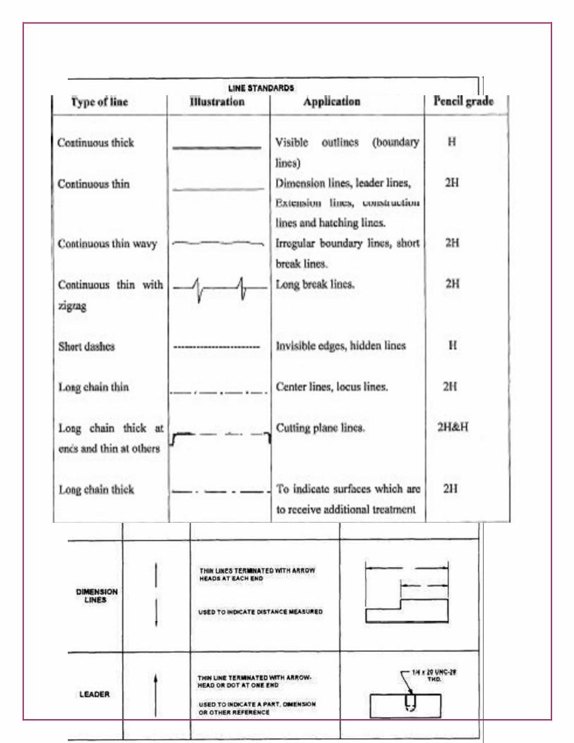
Standard Engineering Drawing Line types A variety of line styles graphically represent physical objects. Types of lines include the following: Visible – are continuous lines used to depict edges directly visible from a particular angle. Hidden – are short-dashed lines that may be used to represent edges that are not directly visible. Center – are alternately long- and short-dashed lines that may be used to represent the axes of circular features. Cutting plane – are thin, medium-dashed lines, or thick alternately long- and double short-dashed that may be used to define sections for section views. Section – are thin lines in a pattern (pattern determined by the material being "cut" or "sectioned") used to indicate surfaces in section views resulting from "cutting." Section lines are commonly referred to as "cross-hatching." Types of Lines Engineering drawing uses various types of lines to describe different objects and different purposes. Each type of line in the drawing has different meaning. Line Thickness For most engineering drawings you will require two thicknesses, a thick and thin line. The general recommendations are that thick lines are twice as thick as thin lines.
A thick continuous line is used for visible edges and outlines. A thin line is used for hatching, leader lines, short centre lines, dimensions and projections.
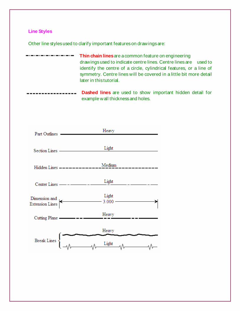
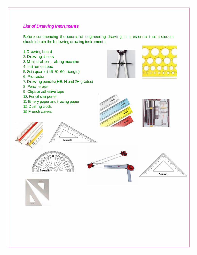
Line Styles Other line styles used to clarify important features on drawings are:
Thin chain lines are a common feature on engineering drawings used to indicate centre lines. Centre lines are used to identify the centre of a circle, cylindrical features, or a line of symmetry. Centre lines will be covered in a little bit more detail later in this tutorial. Dashed lines are used to show important hidden detail for example wall thickness and holes.

Letter size
Pencil for different lines

Lettering All notes and dimensions should be clear and easy to read. In general all notes should be written in capital letters to aid legibility. All lettering should be of the same size and preferably no smaller than 3mm. An example typeface is shown below.
Dimensioning - An Overview A dimensioned drawing should provide all the information necessary for a finished product or part to be manufactured. An example dimension is shown below.
Dimensions are always drawn using continuous thin lines. Two projection lines indicate where the dimension starts and finishes. Projection lines do not touch the object and are drawn perpendicular to the element you are dimensioning. In general units can be omitted from dimensions if a statement of the units is included on your
drawing. The general convention is to dimension in mm. All dimensions less than 1 should have a leading zero. i.e. .35 should be written as 0.35

Dimensioning circles
All dimensions of circles are proceeded by this symbol; . There are several conventions used for dimensioning circles: (a) shows two common methods of dimensioning a circle. One method dimensions the circle between two lines projected from two diametrically opposite points. The second method dimensions the circle internally. (b) is used when the circle is too small for the dimension to be easily read if it was placed inside the circle. A leader line is used to display the dimension. (c) the final method is to dimension the circle from outside the circle using an arrow which points directly towards the centre of the circle. The first method using projection lines is the least used method. But the choice is up to you as to which you use. Dimensioning Holes

When dimensioning holes the method of manufacture is not specified unless they necessary for the function of the product. The word hole doesn't have to be added unless it is considered necessary. The depth of the hole is usually indicated if it isn’t indicated on another view. The depth of the hole refers to the depth of the cylindrical portion of the hole and not the bit of the hole caused by the tip of the drip. Dimensioning Radii All radial dimensions are preceded by the capital R. All dimension arrows and lines should be drawn perpendicular to the radius so that the line passes through the centre of the arc. All dimensions should only have one arrowhead which should point to the line being dimensioned. There are two methods for dimensioning radii. (a) Shows a radius dimensioned with the centre of the radius located on the drawing. (b) Shows how to dimension radii which do not need their centers locating. Spherical dimensions The radius of a spherical surface (i.e. the top of a drawing pin) when dimensioned should have an SR before the size to indicate the type of surface.
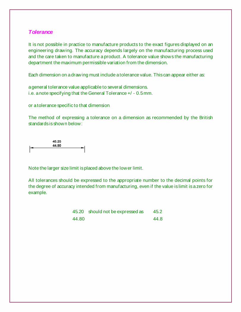
Tolerance It is not possible in practice to manufacture products to the exact figures displayed on an engineering drawing. The accuracy depends largely on the manufacturing process used and the care taken to manufacture a product. A tolerance value shows the manufacturing department the maximum permissible variation from the dimension. Each dimension on a drawing must include a tolerance value. This can appear either as: a general tolerance value applicable to several dimensions. i.e. a note specifying that the General Tolerance +/- 0.5 mm. or a tolerance specific to that dimension The method of expressing a tolerance on a dimension as recommended by the British standards is shown below:
Note the larger size limit is placed above the lower limit. All tolerances should be expressed to the appropriate number to the decimal points for the degree of accuracy intended from manufacturing, even if the value is limit is a zero for example.
45.20 should not be expressed as 45.2 44.80 44.8

Types of sectioning Sectional View in a single plane
The example shows a simple single plane sectional view where object is cut in half by the cutting plane. The cutting plane is indicated on a drawing using the line style used for centre lines, but with a thick line indicating the end of lines and any change in the direction of the cutting plane. The direction of the view is indicated by arrows with a reference letter. The example below shows a sectional view of the cutting plane A - A. Sectional View in two planes
It is possible for the cutting plane to change
directions, to minimise on the number of sectional views required to capture the necessary detail. The example below shows a pipe being cut by two parallel planes. The sketch shows where the object is cut.

Half Sectional views
Half sections are commonly used to show both the internal and outside view of symmetrical objects.
Part Sectional views It is common practice to section a part of an object when only small areas need to be
sectioned to indicate the important details. The example above shows a part sectional view to indicate a through-hole in a plate. Notice that the line indicating the end of the section is a thin
continuous line.

Hatching On sections and sectional views solid area should be hatched to indicate this fact. Hatching is drawn with a thin continuous line, equally spaced (preferably about 4mm apart, though never less than 1mm) and preferably at an angle of 45 degrees. Hatching a single object.
When you are hatching an object, but the object has areas that are separated, all areas of the object should be hatched in the same direction and with the same spacing.
Hatching adjacent objects When hatching assembled parts, the direction of the hatching should ideally be reversed on adjacent parts. If more than two parts are adjacent, then the hatching should be staggered to emphasise the fact that these parts are separate.
Reverse hatching Staggered Hatching
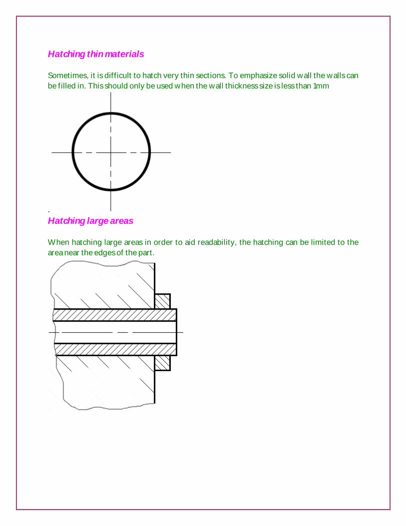
Hatching thin materials Sometimes, it is difficult to hatch very thin sections. To emphasize solid wall the walls can be filled in. This should only be used when the wall thickness size is less than 1mm
. Hatching large areas When hatching large areas in order to aid readability, the hatching can be limited to the area near the edges of the part.
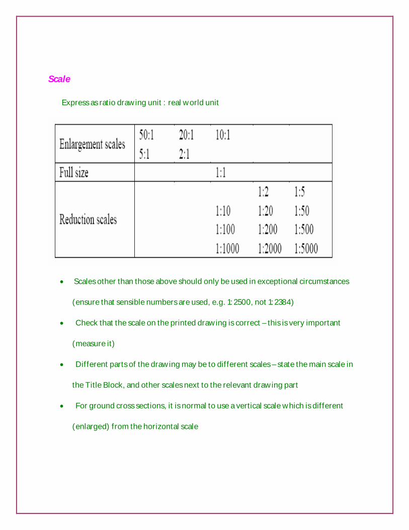
Scale
Express as ratio drawing unit : real world unit
Scales other than those above should only be used in exceptional circumstances
(ensure that sensible numbers are used, e.g. 1:2500, not 1:2384)
Check that the scale on the printed drawing is correct – this is very important
(measure it)
Different parts of the drawing may be to different scales – state the main scale in
the Title Block, and other scales next to the relevant drawing part
For ground cross sections, it is normal to use a vertical scale which is different
(enlarged) from the horizontal scale
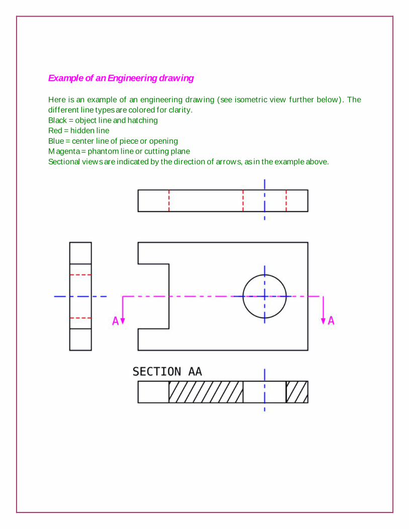
Example of an Engineering drawing Here is an example of an engineering drawing (see isometric view further below). The different line types are colored for clarity. Black = object line and hatching Red = hidden line Blue = center line of piece or opening Magenta = phantom line or cutting plane Sectional views are indicated by the direction of arrows, as in the example above.

Objective questions
1) Engineering drawing deals with ________________.
(a) developing products (b) deciding specifications of the drawing
(c) preparing the product’s drawing (d) manufacturing the product
2) The dimensions of A2 size drawing sheet is ______________ .
(a)1189*841 (b)841*594 (c)594*420 (d)297*210
3) The dimensions of A3 size drawing sheet is _________________ .
(a)1189*841 (b)841*594 (c)594*420 (d)420*297
4) Engineering drawing is an effective language of communication between the
_____________.
(a)supervisors (b)workers (c)manufacturing engineers (d)design engineers
5) ________ is used to draw big drawings in the industry.
(a)A0 sheet (b)A1 sheet (c)A2 sheet (d)A3 sheet
6) A mini drafter is a portable device used to draw ____________.
(a)parallel lines (b)perpendicular lines (c)inclined lines (d)all the above
7) A French curve is used to draw __________________.
(a)polygons (b)circles (c)ellipse (d)smooth freeform curves
8) A title block is placed at ____________________ .
(a)bottom right corner of the drawing (b)top right corner of the drawing
(c)bottom left corner of the draw (d)top left corner of the drawing
9) The dimensions of A4size drawing sheet is __________________.
(a)1189*841 (b)841*594 (c)297*210 (d)420*297
10) Centerline is used to indicate ___________________________.
(a) axis of cylinder (b)axis of symmetry (c)centre line of an object (d)all of the
above
11) The type of line used to indicate a cutting plane is _____________ .
(a)dashed (b)long dashed doted (c)long dashed double dotted (d)continuous
freehand

12) For drawing visible lines _____________ pencils are used.
(a)HB (b)H (c)2H (d)3H
13) If all the horizontal or vertical dimensions of the object start from a common
extension line situated at one end, the way of dimensioning is called ___________.
(a)chain dimensioning (b)parallel dimensioning (c)combined
dimensioning (d)none of the above
14) The symbol indicates __________________.
(a)sectional diameter (b)circle diameter (c)straight diameter (d)none of the
above
15) The abbreviation mm stands for __________________.
(a)mile meter (b)standard units (c)margin marking (d)all of the above
16) What is the area of the drawing sheet of A0 size?
17) The length to width ratio of all the drawing sheet sizes is _________________.
18) Give the location of the title block in the drawing sheet.
19) Visible outlines and edges are drawn as _________________.
20) Centre lines are drawn as _________________.
21) The inclination of inclined lettering is ____________________.
22) Dimensioning lines and hatching lines are drawn as _______________.
23) What is the purpose of sectioning an object?
24) Dimension line should not ______________ each other.
25) How hidden lines are represented?
26) What is a leader line?
27) Explain the two systems of dimensioning.
28) When is chain dimensioning preferred?
29) When is parallel dimensioning preferred?
30) Show the different methods of indicating diameters.

CONIC SECTIONS & SPECIAL CURVES
Contents Conic sections: Introduction
Objective
Cutting plane - sections
Conics Terminology
Types of conics sections
Using Eccentricity method Constructions of
Ellipse
Parabola
Hyperbola
Tangent & Normal
Applications
Summary
Special curves:
Introduction
Cycloids & Involutes
Drawing methodology
Involute of a square
Involute of a circle
Tangent & Normal
Applications
Summary
Objective questions
Assignments

CONIC SECTIONS Objective
1) Upon the completion of the study of this chapter, the student will 2) Define ellipse, parabola, and hyperbola 3) State the geometrical properties of the above plane curves 4) Construct ellipse, parabola & hyperbola using different methods 5) Draw tangent and normal at any point on the above 6) Give a few practical applications of each of them.
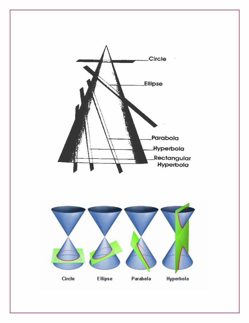
Need for the study Engineering works like construction of arches and bridges, fabrication of light and sound reflectors, manufacture of glands and stuffing boxes, drawing of graphs and machine tool building require the wide use of ellipse, parabola and hyperbola. Hence knowledge of the methods of constructing the se curves is essential for any technician or engineer so that he can execute or supervise the woks with ease and elegance. The geometrical properties, different methods of construction and the practical applications of ellipse parabola and hyperbola are discussed in this chapter. The different position of cutting plane and the respective conic sections obtained are given below the table.
S. No Position of Cutting Plane Shape of the
Section
1 Perpendicular to the axis of cone. Circle
2 Inclined tom the axis and not parallel to any generator. It cuts the generator. Ellipse
3 Inclined to the axis and parallel to the generators Also passes through the base. Here the axis is cut
by the plane Parabola
4 Inclined to the axis at an angle smaller than the
angle of generators to the axis and passes through the plane
Hyperbola
5 Parallel to the axis and perpendicular to the base. It does not pass through the axis but passes through
the base.
Rectangular Hyperbola

Terminologies involved in the Conic Section
1) Focus: The fixed point on the axis is called Focus. 2) Directrix: The fixed straight line is called as Directrix 3) Axis: The line perpendicular to directrix and passing through the focus is called the
Axis. 4) Vertex: The point of intersection of conic section with the axis is called as Vertex. 5) Eccentricity:
Eccecentricity (e)
= Distance of the moving point from focus / Distance of the moving point from directrix i.e. e = FM / AM = Constant
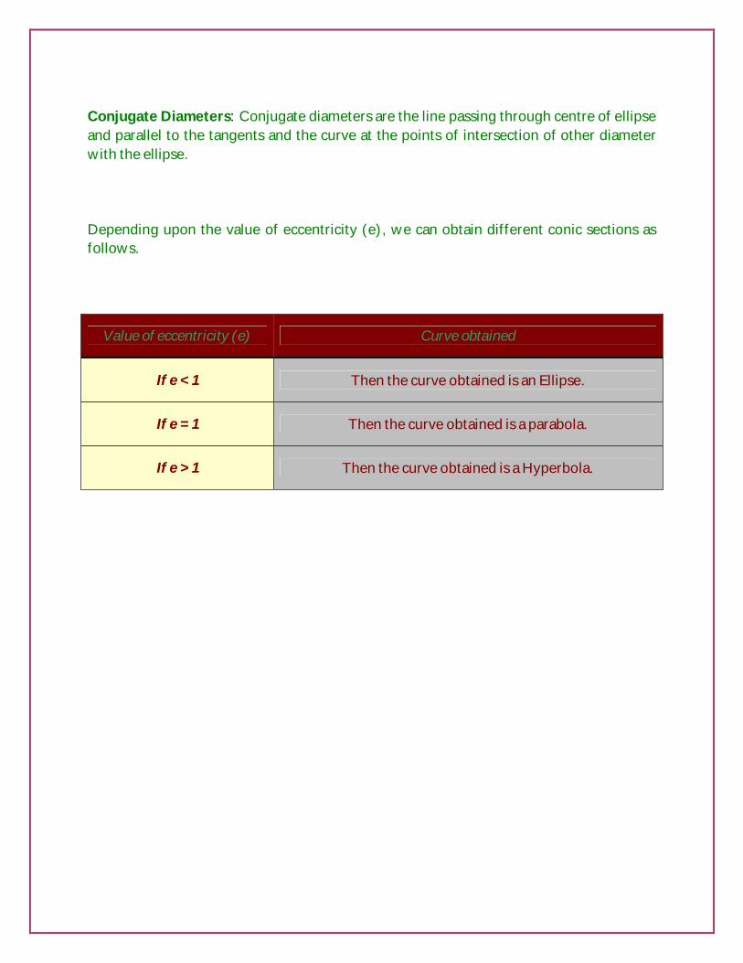
Conjugate Diameters: Conjugate diameters are the line passing through centre of ellipse and parallel to the tangents and the curve at the points of intersection of other diameter with the ellipse. Depending upon the value of eccentricity (e), we can obtain different conic sections as follows.
Value of eccentricity (e) Curve obtained
If e < 1 Then the curve obtained is an Ellipse.
If e = 1 Then the curve obtained is a parabola.
If e > 1 Then the curve obtained is a Hyperbola.

ELLIPSE An ellipse is a curve generated by a point which moves in such a way that the sum of its distances from two fixed points is always a constant. The fixed points are called foci.
Major axis: The line connecting the points A and B and terminated by the curve is called Major axis. Length of the major axis = Distance between A and B Minor axis: The perpendicular line bisecting the major axis and up to the points of intersections of the curve is called Minor axis. Length of ½ major axis = Distance between C and E = Distance between C and F

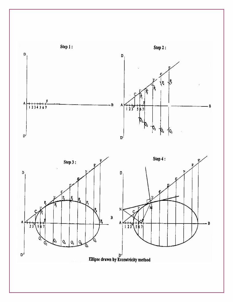
Construction of Ellipse - Eccentricity Method Step 1: Draw the directrix DD’ as a vertical line and the axis AB as a horizontal line.
Mark the focus F on the axis at a given distance from the directrix DD’. Divide AF in to equal parts. The number of equal parts should be sum of numerator and denominator in the eccentricity. Here the eccentricity is taken as ¾. Mark the vertex V as per
VF/AV = eccentricity. Step 2: Draw a vertical line from V and mark C on it such that VC=VF. Then draw a
line through AC for any convenient length.
Draw a vertical line at any convenient distance from vertex V and mark 1 on the axis 1’ on the inclined line AC.
Draw an arc on the line 1-1’with F as centre and 1-1’as the radius to get P1 above the axis and Q1 below the axis. Similarlily draw the vertical line 2-2’ at any convenient distance. Then mark P2 and Q2 with F as centre and 2-2’as radius.
Repeat the above step for P3, P4, P5, …. And Q3, Q4, Q5…. Step 3: Joint all the P and Q points by Step4: To draw tangent and normal to the ellipse
Mark a point M on the curve and connect it with the focus F. Draw a perpendicular line to FM from F to get the point N on the directrix DD’.
Draw a line from N through the point M, which is tangent to the ellipse. Draw a perpendicular line to the tangent passing through the point M. This is the normal to the ellipse.

PARABOLA
The parabola is a plane curve generated by a point moving so that at any position, its distance from a fixed point (Focus) is always exactly equal to its distance from a fixed straight line (Directrix).
Ordinate: Any line from the curve which is perpendicular to the axis is called Ordinate. Double Ordinate: The extension of ordinate up to other side of the parabolic curve. It is twice the length of the ordinate. Abscissa: The distance along the axis between vertex and a point where the ordinate passes is called Abscissa.
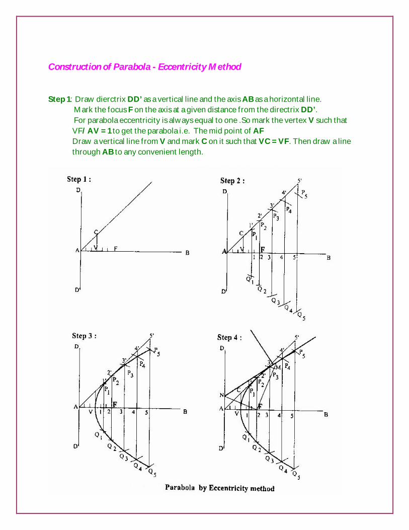
Construction of Parabola - Eccentricity Method Step 1: Draw dierctrix DD’ as a vertical line and the axis AB as a horizontal line. Mark the focus F on the axis at a given distance from the directrix DD’.
For parabola eccentricity is always equal to one .So mark the vertex V such that VF/AV = 1 to get the parabola i.e. The mid point of AF Draw a vertical line from V and mark C on it such that VC = VF. Then draw a line through AB to any convenient length.

Step 2: Draw a vertical line at any convenient distance from V and mark 1 on the axis and 1’ On the line AB.
Draw an arc on the line 1-1’ with F as centre and 1-1’ as radius to get P1 and Q1.
Similarly draw 2-2’ at any convenient distance for P2 and Q2. Repeat the above step to get P3, P4, P5 …and Q3, Q4, Q5 … Step 3: Join all the P and Q points by smooth curve for the required parabola.
HYPERBOLA
The hyperbola is a plane curve generated by a point moving so that the difference of its distances from two fixed points, called the Focuses or Foci, is a constant.
Transverse Axis: The horizontal axis equal to the distance between two vertices of a pair of hyperbola is called Transverse axis. It is also called as Major axis. Conjugate Axis: The line perpendicular to the transverse axis and passing through the centre of transverse axis is called conjugate axis. Foci: The two fixed points which lie on the extension of transverse axis are called Foci.
Construction of Hyperbola - Eccentricity Method
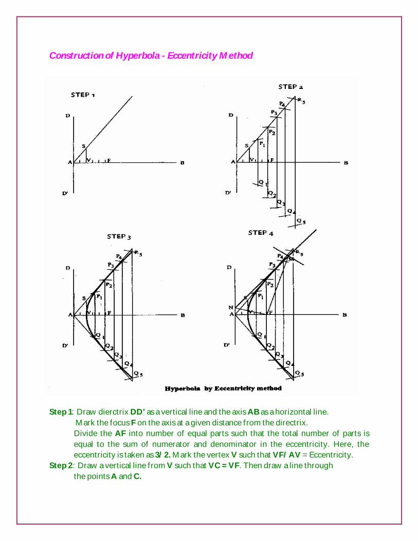
Step 1: Draw dierctrix DD’ as a vertical line and the axis AB as a horizontal line. Mark the focus F on the axis at a given distance from the directrix.
Divide the AF into number of equal parts such that the total number of parts is equal to the sum of numerator and denominator in the eccentricity. Here, the eccentricity is taken as 3/2. Mark the vertex V such that VF/AV = Eccentricity.
Step 2: Draw a vertical line from V such that VC = VF. Then draw a line through the points A and C.
Step 3: Draw a vertical line at any convenient distance from the vertex. Mark the point 1 on the axis and 1’ on the line AC. Cut arcs with F as Centre 1-1’ as radius to get the points P1 and Q1. Step 4: Repeat the above steps for P2, P3, P4, … and Q2, Q3, Q4, …
Join all the P and Q points drawing a smooth curve to obtain the required hyperbola.
Applications of Conic sections Ellipse
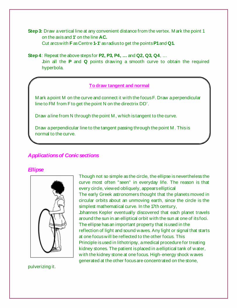
Though not so simple as the circle, the ellipse is nevertheless the curve most often "seen" in everyday life. The reason is that every circle, viewed obliquely, appears elliptical The early Greek astronomers thought that the planets moved in circular orbits about an unmoving earth, since the circle is the simplest mathematical curve. In the 17th century, Johannes Kepler eventually discovered that each planet travels around the sun in an elliptical orbit with the sun at one of its foci. The ellipse has an important property that is used in the reflection of light and sound waves. Any light or signal that starts at one focus will be reflected to the other focus. This Principle is used in lithotripsy, a medical procedure for treating kidney stones. The patient is placed in a elliptical tank of water, with the kidney stone at one focus. High-energy shock waves generated at the other focus are concentrated on the stone,
pulverizing it.
To draw tangent and normal Mark a point M on the curve and connect it with the focus F. Draw a perpendicular line to FM from F to get the point N on the directrix DD’. Draw a line from N through the point M, which is tangent to the curve. Draw a perpendicular line to the tangent passing through the point M. This is normal to the curve.

The principle is also used in the construction of "whispering galleries" such as in St. Paul's Cathedral in London. If a person whispers near one focus, he can be heard at the other focuses, although he cannot be heard at many places in between. http://mathworld.wolfram.com/Ellipse.html http://en.wikipedia.org/wiki/Ellipse The parabola
It is the locus of a point moving in plane in such a way that the ratio of its distance from a point to the fixed straight line is a constant .It is always = 1. http://mathworld.wolfram.com/Parabola.html http://en.wikipedia.org/wiki/Parabola
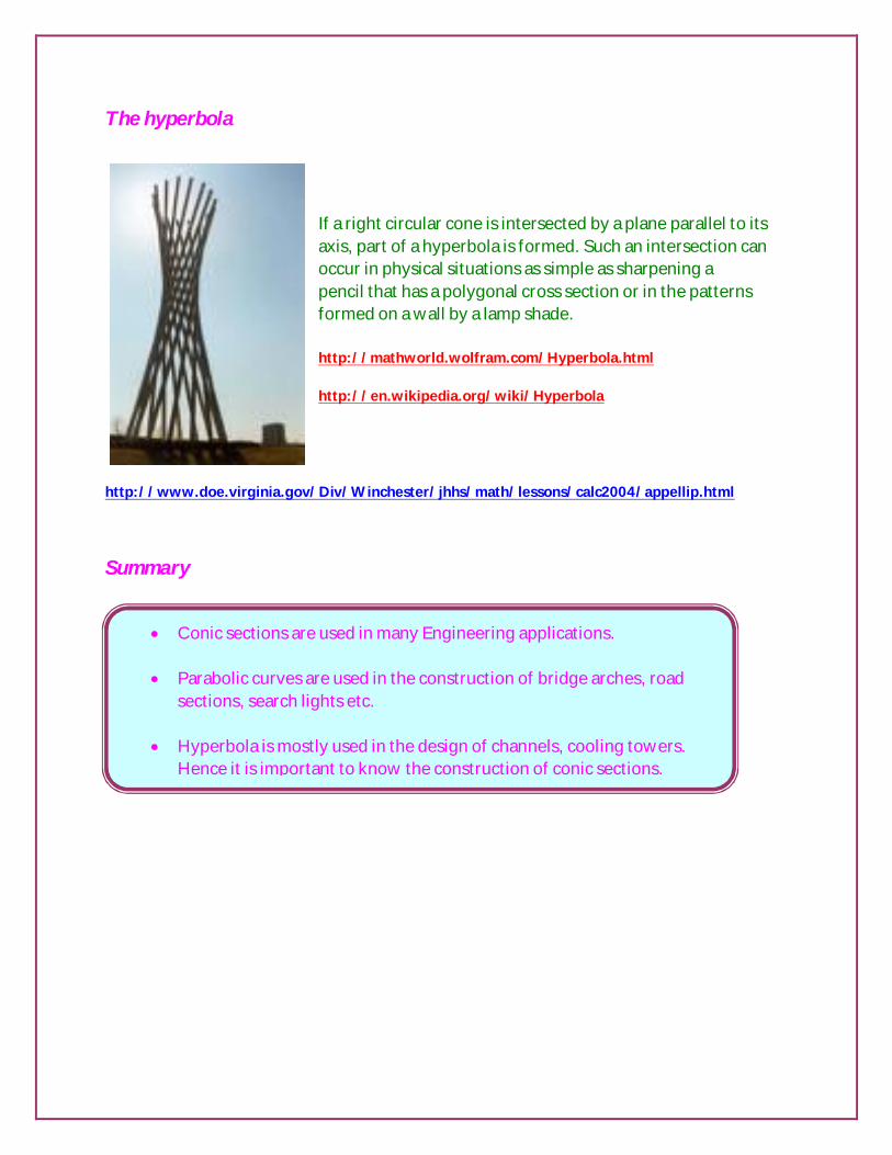
The hyperbola
If a right circular cone is intersected by a plane parallel to its axis, part of a hyperbola is formed. Such an intersection can occur in physical situations as simple as sharpening a pencil that has a polygonal cross section or in the patterns formed on a wall by a lamp shade. http://mathworld.wolfram.com/Hyperbola.html http://en.wikipedia.org/wiki/Hyperbola
http://www.doe.virginia.gov/Div/Winchester/jhhs/math/lessons/calc2004/appellip.html
Summary
Conic sections are used in many Engineering applications. Parabolic curves are used in the construction of bridge arches, road
sections, search lights etc. Hyperbola is mostly used in the design of channels, cooling towers.
Hence it is important to know the construction of conic sections.
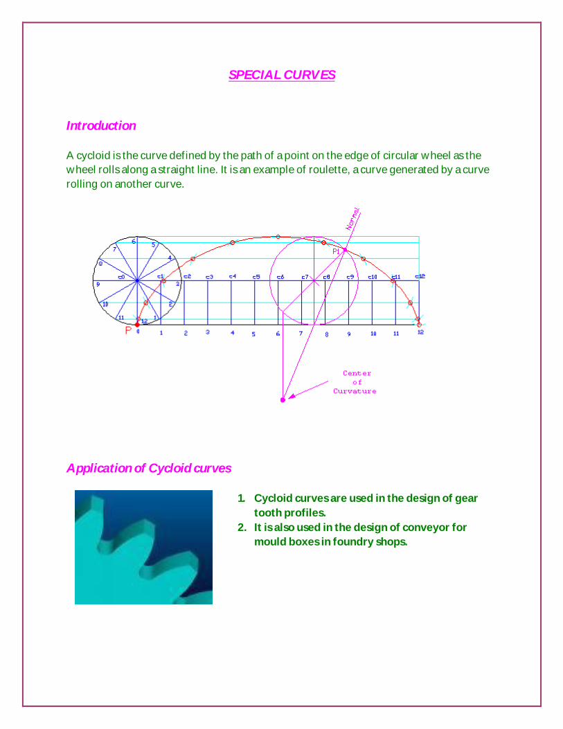
SPECIAL CURVES Introduction A cycloid is the curve defined by the path of a point on the edge of circular wheel as the wheel rolls along a straight line. It is an example of roulette, a curve generated by a curve rolling on another curve. Application of Cycloid curves
1. Cycloid curves are used in the design of gear
tooth profiles. 2. It is also used in the design of conveyor for
mould boxes in foundry shops.

INVOLUTES Introduction Some geometric figures are not bound by straight lines and arcs. They have no closed form but continue to spiral. This type of geometric figure is called an involute. Gear teeth and interlocking mechanisms are often depicted using this type of figure. Involutes An involute is the path of a point on a string as it unwinds from a line, polygon, or circle. Involutes are compound tangential arcs and semicircles of increasing larger diameters formed by lines, triangles, squares, and circles. Involute of a square
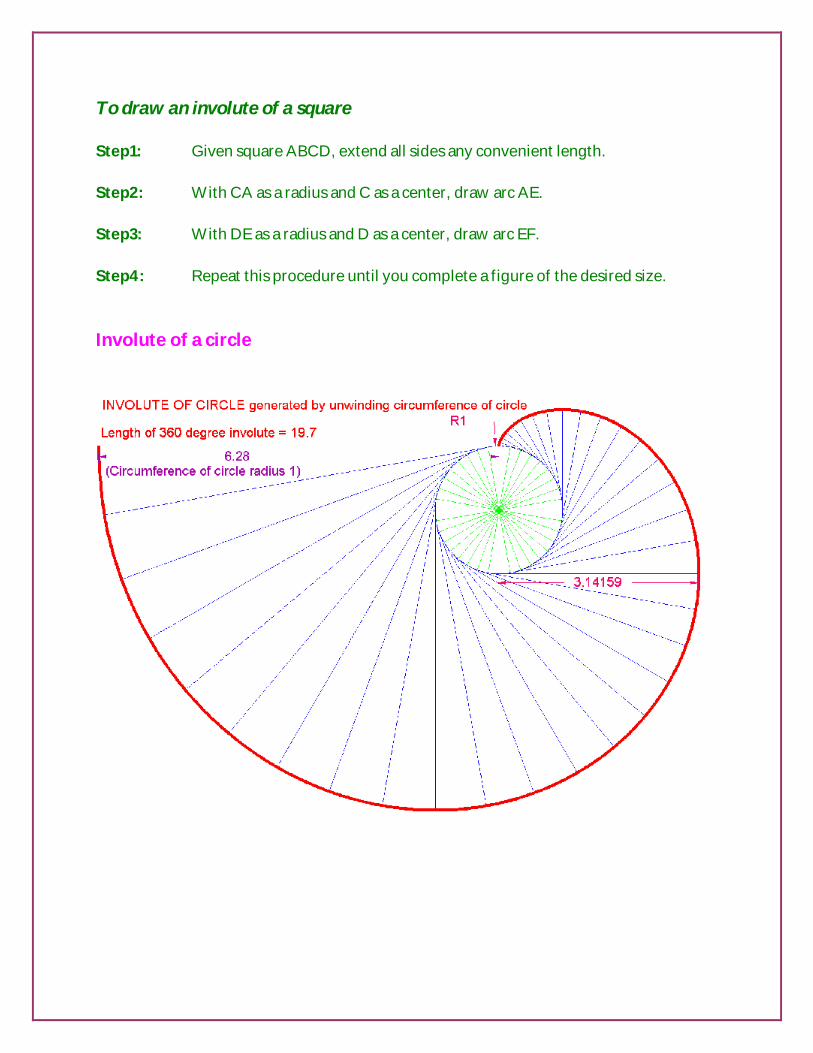
To draw an involute of a square Step1: Given square ABCD, extend all sides any convenient length. Step2: With CA as a radius and C as a center, draw arc AE. Step3: With DE as a radius and D as a center, draw arc EF. Step4: Repeat this procedure until you complete a figure of the desired size. Involute of a circle
- Summary
Objective questions
1) An ellipse has..................... (a) one directrix (b) two directrices (c) one axis (d) none of the above
2) When a cone is cut by a plane inclined at an angle with vertical greater of the cone,
the section is .................
(a) ellipse (b) parabola (c) hyperbola (d) circle
3) Distance of vertex from its directrix is equal to the distance from its focus. The
curve must be ...............
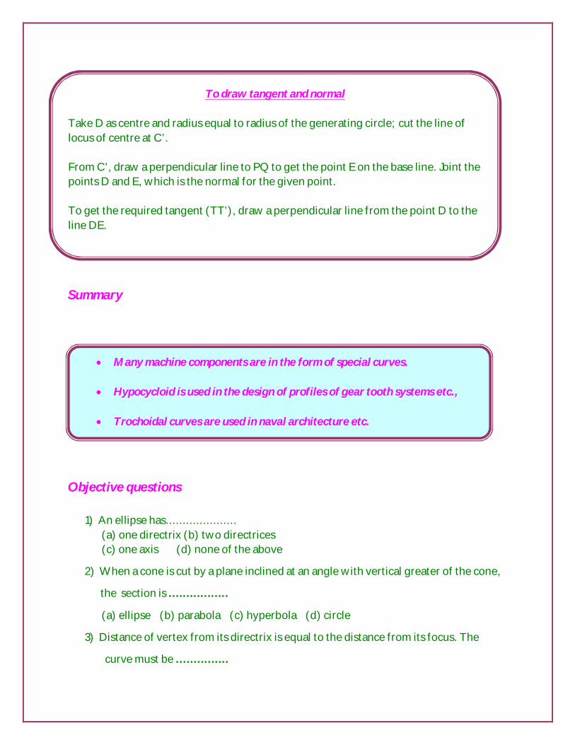
To draw tangent and normal Take D as centre and radius equal to radius of the generating circle; cut the line of locus of centre at C’. From C’, draw a perpendicular line to PQ to get the point E on the base line. Joint the points D and E, which is the normal for the given point. To get the required tangent (TT’), draw a perpendicular line from the point D to the line DE.
Many machine components are in the form of special curves.
Hypocycloid is used in the design of profiles of gear tooth systems etc.,
Trochoidal curves are used in naval architecture etc.
(a) ellipse (b) parabola (c) hyperbola (d) none of the above
7) Which terminology is not involved in conic section?
(a) focus (b) axis (c) length (d) vertex
8) Eccentricity is the ratio between distance of the moving point from focus
to………………..
(a) distance of the moving point from focus (b) distance of the moving point from
vertex (c) distance of the moving point from directrix (d) all of the above
9) Which curve is having two focus points?
(a) ellipse (b) parabola (c) hyperbola (d) rectangular hyperbola
7) Satellite revolving orbit is the application of ……………..
(a) ellipse. (b) parabola (c) hyperbola (d) all of the above
8) Radio navigation path is the application of …………………..
(a) ellipse (b) parabola (c) hyperbola. (d) all of the above
9) A curve generated by a point on the circumference of a circle as the circle rolls
along a straight line is…………..
(a) special curve (b) cycloidal curve (c) involute (d) all of the above
10) Linear distance traveled by one complete revolution of a generator is equal to
…………………
(a) circumference of the circle (b) circumference of the generator (c) 3.14 times
diameter (d)all of the above
11) Involute of polygon is having …………… base surface
(a) Polygonal (b) triangular (c) pentagonal (d) none of the above
12) Spring is the application of
(a) cycloid (b) involute (c) helix (d)all of the above
13) Gear tooth is the application of
(a) cycloid (b) involute (c) helix (d)hypocycliod
14) Formula used to find in hypocycloid is
(a) r/R X 360 (b) R/r X 360 (c) r X 360 (d) R X 360

15) Tangent of a cycloid is having …………………. touching points.
a) one (b) two (c) n numbers (d) none of the above
16) Name the solids of revolution.
17) When a cone is cut by planes at different angles, the intersection curves obtained
are known as ________________.
18) On a conic, the vertex is the point at which the _____________ cuts the
____________.
19) What are the asymptotes to a hyperbola?
20) What is a rectangular hyperbola?
21) Define generating circle.
22) Define directing circle.
23) Define directing line.
24) ______________ are the curves generated by a fixed point on the circumference of
a rolling circle.
25) The difference of the focal distances from any point on an ellipse is constant.
(True/False)
26) Intersection curve between a sphere and any section plane is always a circle.
(True/False)
27) The distance of the ends of the major axis of an ellipse from the centre is equal to
half the minor axis. (True/False)
28) The size of the cycloidal curve is the same, irrespective of the size of the
generating circle. (True/False)
29) Define ellipse, parabola and hyperbola.
30) Define cycloid and involutes.

Assignment questions Ellipse, Parabola & Hyperbola – Eccentricity method
1. Construct an ellipse when the distance of its focus from its directrix is equal to 50mm and the eccentricity is 2/3. Also draw a tangent and a normal to the ellipse.
2. Construct an ellipse when the distance of its focus from its directrix is equal to
60mm and the eccentricity is 3/4. Also draw a tangent and a normal to the ellipse.
3. Construct a parabola when the distance between focus and the diretrix is 50mm. Draw tangent and normal at any point on the curve.
4. Construct a parabola when the distance between focus and the diretrix is 55mm.
Draw tangent and normal at any point on the curve.
5. Construct a hyperbola when the distance between the focus and the directrix is 40mm and the eccentricity is 4/3. Draw a tangent and normal at any point on the hyperbola.
6. Construct a hyperbola when the distance between the focus and the directrix is
70mm and the eccentricity is 3/2. Draw a tangent and normal at any point on the hyperbola.
Cycloids and Involutes
1. A coin of 40mm diameter rolls over a horizontal table without slipping. A point on the circumference of the coin is in contact with the table surface in the beginning and after one complete revolution. Draw the cycloidal path traced by the point. Draw a tangent and normal at any point on the curve.
2. Draw a cycloid when the diameter of generating circle is equal to 50mm.
3. Draw an involute of an equilateral triangle of side equal to 25mm.
4. Draw an involute of a given square of side equal to 15mm.
5. Draw an involute of a given pentagon of side equal to 20mm.
6. Draw an involute of a given hexagon of side equal to 20mm.
7. Draw an involute of a given circle of diameter 40mm.
8. A coir is unwound from a drum of 400mm diameter. Draw locus of free end of the coir for unwounding through an angle of 360°. Also draw a normal and tangent at any point on the curve.