UNIT I – ELECTRIC DRIVES AND TRACTION PART - … Electric Energy...UNIT I – ELECTRIC DRIVES AND...
37
UNIT I – ELECTRIC DRIVES AND TRACTION PART - A 1. List the advantages and disadvantages of electric traction. (Nov – 2017/Nov - 2014) Advantages It has great passenger carrying capacity at higher speed. High starting torque. Less maintenance cost. Cheapest method of traction. Disadvantages High capital cost. Problem of supply failure. Additional equipment is required for achieving electric braking and control. 2. Define gear ratio. (Nov - 2017) Gear ratio = (Input Speed)/ (Output Speed) = (Diameter of output gear) / (Diameter of input gear) 3. What are the merits and demerits of DC system of track electrification? (May - 2017) Merits Better torque-speed characteristic. Low maintenance cost. The weight of d.c motor per H.P is less in comparison to a.c motors. Efficient regenerative braking as compared to single phase a.c series motors. De – merits The overall cost is more because of heavy cost of additional substation equipment This system is preferred for suburban services and road transport where there are frequent stops and distance is less. 4. Give the expression for total tractive effort. (Nov- 2016/May – 2014/May 2012) Total tractive effort required to run a train on track = (Tractive effort to produce acceleration + Tractive effort to overcome effect of gravity + Tractive effort to overcome train resistance) F T = F a + F g +F r 5. What are the recent trends in electric traction? (Nov – 2016/Nov -2014/May - 2014) Magnetic levitation, Maglev (Or) Magnetic suspension and Pseudo - Levitation 6. What are the factors governing scheduled speed of a train? (May - 2016) Acceleration and braking retardation Maximum or Crest speed Stopping time or Duration of stop 7. What are the different systems of traction? Direct team engine drive Direct internal combustion engine drive Steam electric drive Internal combustion engine electric drive Petrol electric traction Battery electric drive 8. Define specific energy consumption and discuss the factors which effect the specific energy consumption. (May - 2015)
Transcript of UNIT I – ELECTRIC DRIVES AND TRACTION PART - … Electric Energy...UNIT I – ELECTRIC DRIVES AND...

UNIT I – ELECTRIC DRIVES AND TRACTIONPART - A1. List the advantages and disadvantages of electric traction. (Nov – 2017/Nov - 2014)
Advantages It has great passenger carrying capacity at higher speed.
High starting torque.
Less maintenance cost.
Cheapest method of traction. Disadvantages
High capital cost.
Problem of supply failure.
Additional equipment is required for achieving electric braking and control. 2. Define gear ratio. (Nov - 2017)
Gear ratio = (Input Speed)/ (Output Speed) = (Diameter of output gear) / (Diameter of inputgear)3. What are the merits and demerits of DC system of track electrification? (May - 2017)
Merits Better torque-speed characteristic.
Low maintenance cost.
The weight of d.c motor per H.P is less in comparison to a.c motors.
Efficient regenerative braking as compared to single phase a.c series motors. De – merits
The overall cost is more because of heavy cost of additional substationequipment
This system is preferred for suburban services and road transport wherethere are frequent stops and distance is less.
4. Give the expression for total tractive effort. (Nov- 2016/May – 2014/May 2012)Total tractive effort required to run a train on track = (Tractive effort to produce acceleration
+ Tractive effort toovercome effect of gravity + Tractive effort toovercome train resistance)
FT = Fa + Fg +Fr
5. What are the recent trends in electric traction? (Nov – 2016/Nov -2014/May - 2014)Magnetic levitation, Maglev (Or) Magnetic suspension and Pseudo - Levitation
6. What are the factors governing scheduled speed of a train? (May - 2016) Acceleration and braking retardation
Maximum or Crest speed
Stopping time or Duration of stop7. What are the different systems of traction?
Direct team engine drive
Direct internal combustion engine drive
Steam electric drive
Internal combustion engine electric drive
Petrol electric traction
Battery electric drive8. Define specific energy consumption and discuss the factors which effect the specificenergy consumption. (May - 2015)
Specific Energy Consumption = (Specific Energy Output at driving wheel)/ (Over allefficiency of the
motors and gearing) Factors
Distance between the stops
Train resistance
Acceleration and retardation
Gradient
Train equipment9. What are the various methods for controlling the speed of d.c series motor? (May -2015)
Rheostatic control
Series parallel control
Field control
Buck and boost method
Metadyne control
Thyristor control 10. List the requirements of ideal traction system. (Nov - 2013)
The starting tractive effort should be high so as to have rapid acceleration.
The wear on the track should be minimum.
The equipment should be capable of withstanding large temporary loads.
Speed control should be easy.
Pollution free. 11. What are the requirements of a braking system?
It should be simple, robust ,quick and reliable in action
Easy to use for driver to operator
Maintenance should be minimum
The braking system should be inexhaustible
In case of emergency braking, safety consideration is taken into account.
Kinetic energy of the train must be storable during braking which could be usedsubsequently during acceleration of the train.
12. Name the various systems of current collection system and where they employed? Trolley collector.
Bow collector
Pantograph collector
13. Name the advanced methods of speed control of traction motors. Tape changer method
Thyristor control
Chopper control
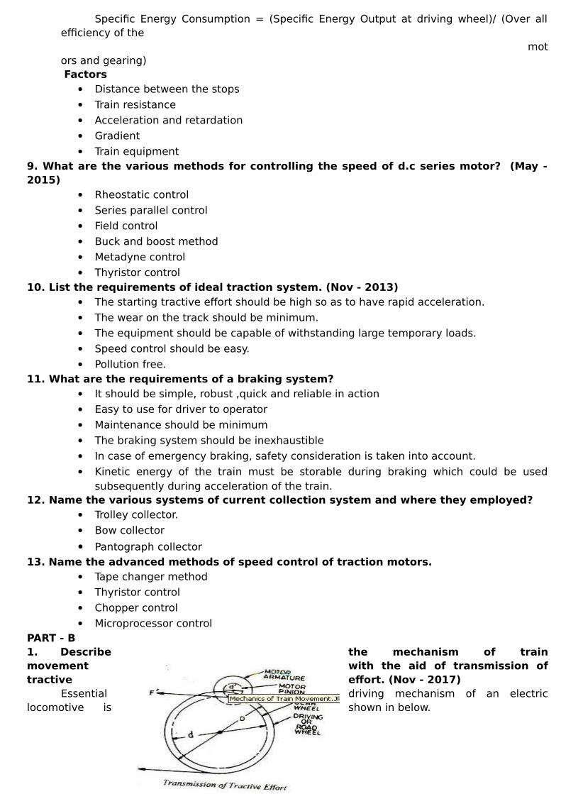
Microprocessor control PART - B1. Describe the mechanism of trainmovement with the aid of transmission oftractive effort. (Nov - 2017)
Essential driving mechanism of an electriclocomotive is shown in below.

The armature of the driving motor has a pinion diameter d‟ attached to it. The tractive effortat the edge of the pinion is transferred to the driving wheel by means of a gear wheel.
F = η F (d/D0 = η 2T/D) = ηT (2/D) (d/d) = ηT 2y/D Where T is the torque exerted in N-m, by the driving motor d is the diameter of gear wheel in metres
D is the diameter of driving wheel in metresη is the transmission efficiency γ is the gear ratio and is equal to d/d
Total tractive effort required to run a train on track = (Tractive effort to produce acceleration+ Tractive effort to overcomeeffect of gravity + Tractive effort to overcometrain resistance)
FT = Fa + Fg +Fr
2. Explain in detail about different methods of traction motor control. (Nov- 2017)The control of traction motors for starting and for smooth acceleration is very much essential
to avoid damage to the motors. The control equipment is provided for manual and automaticoperation. Usually a master controller is used for the purpose.
1. D.C series motor control or plain rheostat control 2. Series –Parallel control
i. Open circuit transition ii. Shunt transition control iii. Bridge transition control
3. Metadyne control 4. Multiple unit control
3. Discuss in detail about series parallel control of electric traction motor with example.(Nov-2017)
Two motors are used. At starting they are connected in series for full speed, they are connected in parallel.
Shunt or short circuit transition method
Bridge transition methodShunt transition methods
Full seriesFirst transitionSecond transition
Bridge transition methodFirst seriesFull seriesTransition
Shunt transition methods

Bridge transition method
4. What are the
factors influencing the choice of electric drives? (May - 2017)An electric drive is defined as a form of machine equipment designed to convert
electric energy into mechanical energy and provide electrical control of this process.Steady state requirementsTransient operation requirementsEnvironmental effectsEffects of supply variationPower factorBraking requirementsPower / Weight RatioCapital cost
5. State the principle of regenerative braking. Explain regenerative braking in respectof DC motors. (May - 2017)
In this type of braking the motor is not disconnected from the supply but remains connectedto it and its feeds back the braking energy or its kinetic energy to the supply system. The essentialcondition for this is that the induced emf should be slightly more than the supply voltage. Thismethod of braking cannot be used for synchronous motors.
In a DC machine where energy will be taken from the supply or delivered to it depends uponthe induced emf, if it in less than the line voltage the machine will operate as motor and if itis more than the line voltage, the machine will operate as generator. The e.m.f induced in turn depends upon the speed and excitation that is when the fieldcurrent or the speed is increased the induced e.m.f exceeds the line voltage and the energywill be field into the system. This will quickly decrease the speed of the motor and will bringit to rest.
6. State the requirements of an ideal traction system. (Nov - 2016)High adhesion coefficient, so that high tractive effort at the start is possible to have rapid acceleration. The locomotive or train unit should be self contained so that it can run on any route.
Minimum wear on the track. It should be possible to overload the equipment for short periods. The equipment required should be minimum, of high efficiency and low initial and maintenance cost. It should be pollution free. Speed control should be easy. Braking should be such that minimum wear is caused on the brake shoes, and if possible the energy should be regenerated and returned to the supply during braking period.
7. List the various sources for Electric traction.(Nov-2016)All traction systems, broadly speaking, can be classified as follows:
Non-electric traction systems: These systems do not use electrical energy at some stage or the other. Examples: Steam engine drive used in railways at some stage or the other.
These are further sub divided into the following two groups: a) Self contained vehicles or locomotives
Examples: i) Battery-electric drive ii) Diesel-electric drive
b) Vehicles which receive electric power from a distribution network or suitably placed sub-stations.
Examples: i) Railway electric locomotive fed from overhead A.C supply; ii) Tramways and trolley buses supplied with D.C.supply.
Electric traction systems may be broadly categorized as those operating on: Alternating current supply Direct current supply.
In general following electric traction systems exist: a) AC 3 phase 3.7 kV system b) AC single phase 15/16 kV -161/25 Hz c) AC single phase 20/25 kV - 50/60 Hz d) DC 600 V e) DC 1200 V f) DC 1.5 kV g) DC 3 kV.
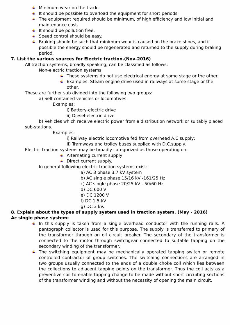
8. Explain about the types of supply system used in traction system. (May - 2016)Ac single phase system:
In this supply is taken from a single overhead conductor with the running rails. Apantograph collector is used for this purpose. The supply is transferred to primary ofthe transformer through on oil circuit breaker. The secondary of the transformer isconnected to the motor through switchgear connected to suitable tapping on thesecondary winding of the transformer. The switching equipment may be mechanically operated tapping switch or remotecontrolled contractor of group switches. The switching connections are arranged intwo groups usually connected to the ends of a double choke coil which lies betweenthe collections to adjacent tapping points on the transformer. Thus the coil acts as apreventive coil to enable tapping change to be made without short circuiting sectionsof the transformer winding and without the necessity of opening the main circuit.
Direct current systems: The transformation and high voltage generation of dc is very inconvenient to the dcsupply used is at normally 600 V and this voltage is almost universal for use in urbanand suburban railways. For direct current equipment, the series motor is universally employed as its speed-torque characteristics are best suited to traction requirements. Generally two or moremotors are used in single equipment and these are coupled in series or in parallel togive the different runningspeeds required. The motors are initially connected in series with starting rheostats across the contactline and rails, the rheostats are then cut out in steps, keeping roughly constant currentuntil the motors are running in full series. After this the motors are rearranged inparallel, again with rheostats, the rheostats are cut out in steps, leaving the motors infull parallel.
9. What are the various types of electric braking used in traction? Discuss in detail. (May - 2015)
1. Magnetic braking:In this case the excitation of the armature is disconnected from the supply but theexcitation remains on. When the armature rotates in the fixed field, there is reversal offlux in the armature and the iron losses are fed from the kinetic energy of the rotatingcomponents and the machine retards. This method can be adopted for shunt,compound and synchronous motors. In case of series motors the field cannot standthe full rated voltage, so separate battery has to provide for excitation during braking.
2. Plugging:In this case the connections of excitation are reversed. The motor tends to rotate inthe reverse direction. Care should be taken to disconnect the motor when it has juststopped this method can be used for small motors and is not suitable for tractionmotors which are generally of large size.
3. Resistance braking:In this the motor after switching off is made to run as a generator. The output ofgenerator is consumed in resistance thereby causing retardation.
4. Regenerative braking:In this method although motor is made to run as a generator but the current insteadof being fed to a resistance is fed to the mains. The essential condition for this is thatthe induced emf should be slightly more than the supply voltage. This method ofbraking cannot be used for synchronous motors.
10. Sketch the typical speed-time curve for main line service and to sub urban servicesin electric traction (May - 2017)
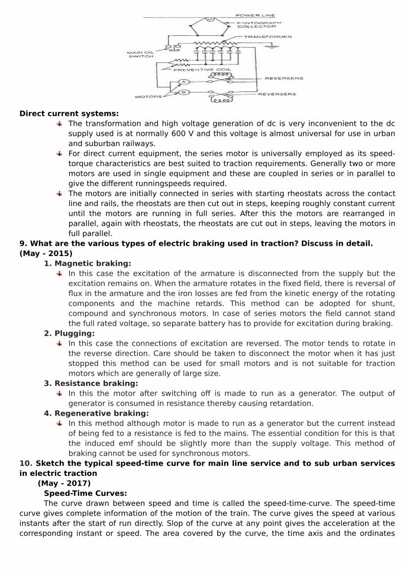
Speed-Time Curves: The curve drawn between speed and time is called the speed-time-curve. The speed-time
curve gives complete information of the motion of the train. The curve gives the speed at variousinstants after the start of run directly. Slop of the curve at any point gives the acceleration at thecorresponding instant or speed. The area covered by the curve, the time axis and the ordinates
through the instants between which the time is taken, represents the distance covered in thecorresponding time interval
Speed-time curve mainly consists of 1) Initial acceleration 2) Constant speed run or free run 3) Coasting and 4) Retardation or braking
1. Acceleration period: From starting to the stage when locomotive attains maximum speed, the period is known as
acceleration period, as the vehicle is constantly accelerated. This is represented by OA portion ofthe curve and time duration is t1.2. Free running:
During this period the motor develops enough torque to overcome the friction and windresistance and hence the locomotive runs at constant speed. This is shown by the portion AB of thecurve. 3. Coasting:
When the locomotive is running at certain speed, if the motor is switch off, due to inertia thevehicle will continue to run, of course with little deceleration due to friction and windage. 4. Braking:
The locomotive is retarded to stop it within short distance and at a particular spot. The shapeof the curve will change depending upon the distance between consecutive stations.11. A 250 tones train with 10% rotational inertia effect is started with uniform acceleration and reaches a speed of 50kmphps in 25 seconds on level road. Find the specific energy consumption if the journey is to be made according to trapezoidal speed– time curve. Acceleration = 2kmphps; Tracking retardation=3kmphps; Distance between the station =2.4km; Efficiency =0.9; Track resistance=5 Kg/tones. (May - 2017)
Accelerating Period = t1= Vm/⍺=50/2=25SecBraking Period = t3=Vm/ᵦ=50/3=16.67SecFree running Period = t2=T-(t1+t3)=265-(25+16.67)=223.33SecTractive Effort Ft=277.8We⍺+98.1WG+Wr=189687.5NFree running= 14273.55NTotal Energy output=21.438kWhTotal Energy Consumption = (Total Energy Output)/(Efficiency)=23.82kWhSpecific Energy Consumption = (Total Energy Consumption)/(Weight in tonnes*Distance of
run in km)=39.7wh/ton-km
UNIT II – ILLUMINATIONPART - A1. Why tungsten is selected as the filament material? (Nov – 2017/Nov - 2016)
Voltage fluctuation has comparatively more effect on the light output.
Initial cost is low.
It gives light close to natural light; therefore objects are properly seen.
Its brightness is more.2. Define the term MSCP and lamp efficiency. (Nov – 2017)
The mean of candle power in all directions and in all planes from the source of light is termedas Mean Spherical Candle Power.
Lamp efficiency is defined as the ratio of the luminous flux to the power input. It is expressedin lumens per watt.3. What do you understand by polar curves as applied to light source?(May - 2017)
A curve is plotted between candle power and the angular position. The luminous intensity inall the directions can be represented by polar curves.
Uses: To determine the MHCP, MSCP and the actual illumination of a surface by employingthe candle power in that particular direction.4. What is flood lighting where is it generally used? (May - 2017)
Flood lighting means flooding of large surfaces with light from powerful projectors. It isemployed to serve for the following purposes.
Aesthetic Flood Lighting
Industrial and Commercial Flood Lighting
Advertising5. Specify any four energy efficient lamps.(Nov - 2016)
Compact Fluorescent Lamp (CFL)
Metal Halides Lamps
High Pressure Sodium Vapor Lamp
LED6. Define the term luminous efficacy. (May -2016)
It is a measure of how well a light source produces visible light. It is the ratio of luminous fluxto power.7. Suggest suitable lamps for sports ground lighting application. (May - 2016)
High Pressure and Low Pressure Sodium Vapor Lamps.8. Define the term luminous flux. (Nov - 2015)
It is the rate of energy radiation in the form of light waves and is denoted by Ф=Qt where Qis the radiant energy. Its unit is lumen.9. State the different types of electrical lamps used for illumination. (Nov – 2015 / May -2014)
Arc lamps
High temperature lamps
Gaseous discharge lamps
Fluorescent lamps. 10. List the types of lighting system. (Nov-2014)
Direct lighting
Indirect lighting
Semi-direct lighting
Semi-indirect lighting 11. Define lumen. (Nov – 2014 / May - 2014)
One lumen is defined as the luminous flux emitted by a source of one candle power in a unitsolid (i.e.)
lumen = candle power of source × solid angle12. What are the requirements of good lighting?
Provide sufficient illumination
Provide uniform light distribution all over the working plane
Provide light of suitable colour

Avoid glare and shadow PART- B1. Explain the detail the principle of operation of fluorescent lamp. (Nov – 2017/ Nov -2016) Circuit Diagram
WorkingEmploys transformation of UV radiation due to low pressure mercury vapor.Luminescent Powder in tubular vapor Lamps Enhances brilliancy of light. Radiationfrom Low Pressure Mercury Vapor (which is in UV region) is impinged on LuminescentMaterials and re – radiated at longer wavelengths of visible spectrum. In a Glass Tube small drop of Mercury and small amount of Argon gas are placed forinitiation of discharge. Pressure, voltage and current are so adjusted that 253.7 nmlines is excited. This re-radiates at longer wavelength. Typically a 40W lamp requires 2-3g of phosphors. Maximum sensitivity is around 250 –260 nm.
2. Describe and prove laws of illumination. (Nov -2017/May -2017/May-2015/May2014/May-2013)Law of inverse squaresIt states that illumination of a surface is inversely proportional to the square of the distance of thesurface from the source of light; under the condition that source is the point source.
22
2 r
IE Lumens/unit area
Lambert’s cosine LawIt states that illumination of a surface at any point is dependent upon the cube of cosine of theangle between the line of flux and the normal at that point.
32cos
h
IERS
3. Explain the working of a sodium vapour lamp with in a neat sketch. (May – 2017/Nov-2015) Circuit
Wo rking
Principally sodium vapour lamp consists of a bulb containing a small amount ofmetallic sodium, neon gas and two sets of electrodes connected to a pin type base.
The lamp operates at a temperature of about 300°C and in order to conserve the heatgenerated and assure the lamp operating at normal air temperatures the dischargeenvelope is enclosed in special vacuum envelope designed for this purpose. The efficiency of a sodium vapour lamp under practical conditions is about 40-50lumens/watt. Such lamps are manufactured in 45, 60, 85 and 140 W ratings. The average life is about 3000 hours and is not affected by voltage variations. Themajor application of this type of lamp is for highway and general outdoor lightingwhere colour discrimination is not required, such as street lighting, parks, rail yards,storage yards etc.
4. Show different types of indoor and outdoor lighting with neat sketches. (May - 2017)Road Lighting:
Conventionally by they are arranged in a column, mounted on a wall or suspended by a spanwire. Plane of Symmetry being in vertical plane perpendicular to the axis of the road along theroad. Flood Lights:
Rain Proof Lamp holder with wide / narrow beam Reflectors are used for flood light.They are usually High wattage Incandescent Lamps, Halogen Lamps, High PressureMercury Vapor Lamp or Low / high Pressure Sodium Lamp. Spot lights / down lights are usually used with Screens, Reflectors, Filters, Coloredenvelope and Closed Lamps.
Interior Lighting: Interior Lighting is a complex problem depending on various factors such as
Purpose intended service,Class of Interiors. Luminary best suited, Colour effect and Reflection from ceiling, walls, floors.
Sports Lighting: Lighting for sports facility looks for comfort of four user groups namely Players,Officials, Spectators and Media. Players and officials should see clearly in the play areato produce best possible results the object used in the game. Spectators should follow the performance of the players. In addition to play areasurroundings also need to be illuminated. Lighting should be such that it enables safeentry and exit. With increasing crowd level safety becomes more and more important. Media include TV and film, for which lighting should provide lighting such thatconditions are suitable for color picture quality as per CIE 83. This should be suitablefor both general pictures as well as close up of players and spectators. Additionally, itshould have provisions for emergency power supply to provide continuoustransmission. Criteria relevant for sports lighting are Horizontal Illuminance, Vertical Illuminance,Illuminance Uniformity, Glare restrictions, Modeling & shadows and Color appearance& rendering
5. List the various types of lamps commercially available. Also specify the energyefficient lamps for domestic and industrial lighting applications. (May -2016)Arc lamps
Carbon arc lampFlame arc lampMagnetic arc lamp
ApplicationsOutdoor lighting, Flashlight in cameraFlood lights ProjectorsEndoscopy etc.,

High temperature lamps Halogen lampCommercial lighting
Gaseous discharge lamps Sodium Vapor lampStreet lighting
Fluorescent lampsResidential lighting
CFL – Compact Fluorescent LampLED – Light Emitting Diode
BenefitsLong lastingDurableMercury freeCost effectiveReduces air and water pollution
6. Explain the various steps involved in designing of lighting system. (May – 2016/Nov-2015)
Watt – per square metre methodIt is more adaptive for rough calculation or checking and its simple calculation.
Lumen (or) Light Flux MethodLumens received on the working plane = Number of lamps X wattage of each lamp X lamp
efficiency (lumens/watt) X coefficient of utilization/depreciation factor.Co-efficient of utilizationMaintenance factorDepreciation factor
Point to Point / Inverse square law methodCalculation of illumination
MFUF
AEN
**
*
7. Explain flood lighting calculation with necessary definitions. (May -2014)Flood lighting means flooding of large surface with light from powerful projectors.
Aesthetic Flood Lighting: Beauty of buildings at night, religious buildings on festive occasionsIndustrial and Commercial: Railway yards, Sports stadium, Car Parks, Construction sites etc.,Advertising: Showcases and advertisement boardThree steps – Calculation
Illumination level required Types of projectorNumber of projectors
ncyousefficieLuampWastageoflUF
factorWastelightDFEAN
min**
***
8. Explain the working of a high pressure mercury vapour lamp with a neat sketch. (May– 2011) Circuit

WorkingThe mercury vapour lamp in construction is similar to sodium vapour lamp. It givesgreenish blue colour light, which causes colour distortion. The efficiency is about 30-40 lumens per watt. These lamps (MA type) aremanufactured in 250 and 400 W ratings for use on 200-250 Vac supply. Lamps of this type are used for general industrial lighting, railway yards, ports, workareas; shopping centres etc where greenish-blue colour light is not objectionable. Another type, which is manufactured in 300 and 500 W ratings for use on ac as well asdc supply mains, is MAT type. This is similar to MA type except that it does not usechoke as ballast. Lower wattage lamps, such as 80 and 125 W, are manufactured in adifferent design and using high vapour pressure of about 5-10 atmospheres. These areknown as MB type lamps.
9. Lighting schemesDirect lighting:
Lighting provided from a source without reflection from other surfaces. In day lighting, thismeans that the light has travelled on a straight path from the sky (or the sun) to the point ofinterest. In electrical lighting it usually describes an installation of ceiling mounted or suspendedluminaires with mostly downward light distribution characteristics. Indirect lighting:
Lighting provided by reflection usually from wall or ceiling surfaces. In day lighting, thismeans that the light coming from the sky or the sun is reflected on a surface of high reflectivity likea wall, a window sill or a special redirecting device. In electrical lighting the luminaries aresuspended from the ceiling or wall mounted and distributes light mainly upwards so it getsreflected off the ceiling or the walls.Indirect Lighting= 90 to 100 percent of the light is directed to the ceilings and upper walls and isreflected to all parts of a room. Semi-Direct Lighting=60 to 90 percent of the light is directed downward with the remainderupward Semi-indirect Lighting=60 to 90 percent of the light is directed upward with the remainderdirected downward. Highlighting Lighting= the beamprojection distance and focusing abilitycharacterize this luminaries10. Incandescent lamp – Constructionand Working Circuit

WorkingThe incandescent light bulb, incandescent lamp or incandescent light globe produceslight by heating a metal filament wire to a high temperature until it glows. The hotfilament is protected from oxidation in the air with a glass enclosure that is filled withinert gas or evacuated. In a halogen lamp, filament evaporation is prevented by a chemical process thatredeposit’s metal vapor onto the filament, extending its life. The light bulb is suppliedwith electrical current by feed-through terminals or wires embedded in the glass. Mostbulbs are used in a socket which provides mechanical support and electricalconnections. Incandescent bulbs are manufactured in a wide range of sizes, lightoutput, and voltage ratings, from 1.5 volts to about 300 volts. They require no external regulating equipment, have low manufacturing costs, andwork equally well on either alternating current or direct current. As a result, theincandescent lamp is widely used in household and commercial lighting, for portablelighting such as table lamps, car headlamps, and flashlights, and for decorative andadvertising lighting.
UNIT III – HEATING AND WELDINGPART - A1. State the requirements of a good heating material. (Nov – 2017 / May – 2017/May-2016)
High resistivity
High melting point
Free from oxidation
Low temperature coefficient2. Differentiate between core type and coreless type induction furnace. (Nov -2017)
Core type Leakage reactance is high Frequency converter is required Odd shape of crucibles is not convenient
Core less type No dust, smoke and noise Fast in operation Any shape of crucibles can be used Erection and operating cost is low
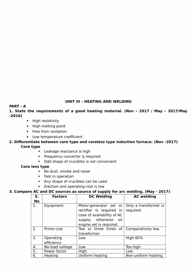
3. Compare AC and DC sources as source of supply for arc welding. (May - 2017)S.No
Factors DC Welding AC welding
1. Equipment Motor-generator set orrectifier is required incase of availability of ACsupply; otherwise oilengine set is required.
Only a transformer isrequired.
2. Prime cost Two or three times oftransformer.
Comparatively low.
3. Operatingefficiency
Low High 85%
4. No-load voltage Low Too high 5. Power factor High Low 6. Heating Uniform heating Non-uniform heating

7. Arc stability Higher - 8. Arc blow Pronounced Not so pronounced
with AC 9. Electrodes Non-coated cheap
electrodes can be used. Only coatedelectrodes-expensive ones.
4. List the advantages of electric heating. (Nov - 2016) Economical
Cleanliness
Absence of flue gases
Ease of control or adaptation
Automatic protection
Upper limit of temperature
Special heating features
High efficiency of utilization
Better working conditions
Safety
Heating of non-conducting materials5. What is meant by resistance welding? (Nov -2016)
A heavy current is passed through the joint required to be welded. The resistance of the jointgenerates enough heat due to I2R loss to melt the metal and causes fusion at the point of contact.6. Mention the merits of dielectric heating. (May - 2016)
Uniform electric field and uniform heat
Higher quality of products
Economic, easy and automatic
Heat takes place in the material itself.7. Define squeeze time. (Nov - 2015)
It is the time that elapses between the initial application of the electrode pressure or thework and the first application of current.8. In electric arc welding what types of electrodes are used in DC supply and AC supply.(Nov - 2015)
DC - Non-coated cheap electrodes can be used
AC - Only coated electrodes- expensive ones9. Mention the factors which limit the choice of frequency in induction and dielectricheating? (May - 2015)
Dielectric heating Non metals like wood, plastics etc., 10 and 30MHz and the voltage up to 20KV.
Induction heating Low temperature : 50-500Hz Heating metal pieces : 1 – 50 MHz Melting : 500 Hz – 10 KHz
10. What is meant by arc welding, also list its type? (May - 2015)An electric arc is the flow of electric current through gases accompanied by heat and bright
glow due to ionization and dissipation of energy of the surrounding medium. The electric arc isstruck by short circuiting two electrodes and then withdrawing them apart.
Types Carbon Arc welding
Metal Arc welding
Gas Metal Arc welding
Gas tungsten Arc welding

Atomic-hydrogen Arc welding
Plasma Arc welding
Submerged Arc welding
Flux-cored Arc welding
Electro slag Arc welding 11. What is the basic principle of induction heating?
It works on the principle of electromagnetic induction as same as a transformer. A metal discis surrounded by a copper coil in which A.C supply is flowing. The disc has a finite value of diameterand thickness and is spaced a given distance from the coil and concentric to it. We find that asecondary current is caused to circulate around the outer surface of the disc.12. What are the modern welding techniques? Drawbacks of convention welding methods
Excessive melting
Diffusion
Formation of inter metallic compounds
Tower ductility
Lower shock resistance capability Modern welding techniques are,
Ultrasonic welding
Laser welding
Electron beam welding 13. What is LASER welding?
LASER (Light Amplification Simulated Emission of Radiation) welding is a welding processthat uses the heat from a laser beam impinging on the joint. The process is without a shielding gasand pressure.
PART - B1. Describe the construction and working principle of dielectric heating. (Nov -2017/May - 2017)
Dielectric heating is also sometimes called as high frequency capacitance heating. If non metallic materials i.e., insulators such as wood, plastics, china clay, glass, ceramicsetc are subjected to high voltage A.C current, their temperature will increase in temperatureis due to the conversion of dielectric loss into heat. The dielectric loss is dependent upon the frequency and high voltage. Therefore for obtaininghigh heating effect high voltage at high frequency is usually employed. When A.C supply is connected across the two electrodes, the current drawn by it is leadingthe voltage exactly 90˚. The angle between voltage and current is slightly less than 90˚ But at high frequencies, the loss becomes large, which is sufficient to heat the dielectric.

Advantages: Uniform heating is obtained. Running cost is low. Non conducting materials are heated within a short period. Easy heat control.
Applications: For food processing. For wood processing. For drying purpose in textile industry. For electronic sewing.
2. Explain the principle and working of welding transformer. (Nov - 2017)The impedance of a welding transformer may be higher that the impedance of a transformer
designed for some other purpose. The transformer impedance may play a role in the process ofestablishing an arc and controlling the current.
A welding transformer is a step down transformer that reduces the voltage from the sourcevoltage to a lower voltage that is suitable for welding, usually between 15 and 45 volts. The secondary current is quite high. 200 to 600 amps would be typical, but it could be muchhigher. The secondary may have several taps for adjusting the secondary voltage to controlthe welding current. The taps are typically connected to a several high-current plug receptacles or to a highcurrent switch. For welding with direct current (DC) a rectifier is connected to the secondaryof the transformer. There may also be a filter choke (inductor) to smooth the DC current. The entire transformerand rectifier assembly may be called a transformer or welder, but "welding power supply"would be more appropriate term.
Special Features: Stepless current control within single range from front panel For its high permitted load, it’s ideal for fematic welding Phase compensation facility optional. It’s a good investment as the primary current and rated output can be reduced, resulting in reduced fuse size and cable diameter Provided with wheels and handle for easy mobility Sturdy design for all working environments Horizontal shunt core travel ensures precise setting after prolonged use Class 'H' insulation provides longer coil life
3. Describe different types of arc welding with neat diagram. (Nov - 2017)An electric arc is the flow of electric current through gases. An electric arc is struck by short circuiting two electrodes and then with drawing them apartby small distance. The current continue to flow across the small gap and give intense heat. The heat developed by the arc is also used for cutting of metal. The electrode is made of carbon or graphite and is to be kept negative with respect of work. The work piece is connected to positive wir. Flux and filler are also used. Filler is made up of similar metal as that of metal to be welded.
If the electrode is made positive then the carbon contents may flow into the weld and causebrittleness. The heat from the arc forms a molten pool and the extra metal required to make the weld issupplied by the filler rod. This type of welding is used for welding copper and its alloy.
Metal arc welding: In metal arc welding a metal rod of same material as being welded is used as an electrode. The electrode also serves the purpose of filler. For metal arc welding A.C or D.C can be used. Electric supply is connected between electrode and work piece. The work piece is then suddenly touched by the electrode and then separated from it a little.This results in an arc between the job and the electrode. A little portion of the work and the tip of the electrode melts due to the heat generated bythe arc. When the electrode is removed the metal cools and solidifies giving a strong welded joint.
4. What are the different types of resistance welding? Describe any one type. (May –2017)
In resistance welding heavy current is passed through the metal pieces to be welded. Heatwill be developed by the resistance of the work piece to the flow of current.
The heat produced for welding is given by H=I2 R t
Where, H= Heat developed at the contact area. I= Current in amperes. R= Resistance in ohms. t= time of flow of current.
Butt welding: In this process heat is generated by the contact resistance between two components. In this type of welding the metal parts to be joined end to end. Sufficient pressure is appliedalong the axial direction. A heavy current is passed from the welding transformer which creates the necessary heat atthe joint due to high resistance of the contact area. Due to the pressure applied, the molten metal forced to produce a bulged joint. This method is suitable for welding pipes, wires and rods.
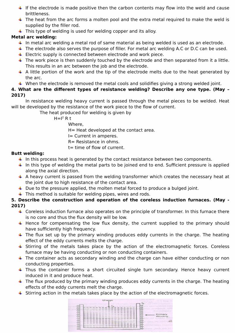
5. Describe the construction and operation of the coreless induction furnaces. (May -2017)
Coreless induction furnace also operates on the principle of transformer. In this furnace thereis no core and thus the flux density will be low. Hence for compensating the low flux density, the current supplied to the primary shouldhave sufficiently high frequency. The flux set up by the primary winding produces eddy currents in the charge. The heatingeffect of the eddy currents melts the charge. Stirring of the metals takes place by the action of the electromagnetic forces. Corelessfurnace may be having conducting or non conducting containers. The container acts as secondary winding and the charge can have either conducting or nonconducting properties. Thus the container forms a short circuited single turn secondary. Hence heavy currentinduced in it and produce heat. The flux produced by the primary winding produces eddy currents in the charge. The heatingeffects of the eddy currents melt the charge. Stirring action in the metals takes place by the action of the electromagnetic forces.

Advantages: Time taken to reach the melting temperature is less. Accurate power control is possible. Any shape of crucible can be used. The eddy currents in the charge results in automatic stirring. Absence of dirt, smoke, noise, etc. Erection cost is less.
6. Draw a neat sketch of induction furnace and explain its working. (Nov -2016) Indirect core type induction furnace:
In this type of furnace induction principle has been used for heating metals. In such furnace an inductively heated element is made to transfer its heat to the change When the primary winding is connected to the supply, current is induced in the secondary ofthe metal container. So heat is produced due to induced current. This heat is transmitted to the charge byradiation. The portion AB of the magnetic circuit is made up of a special alloy and is kept inside thechamber of the furnace. The special alloy will lose its magnetic properties at a particular temperature and themagnetic properties are regained when the alloy will cooled. As soon as the furnace attains the critical temperature the reluctance of the magnetic circuitincreases many times and the inductive effect correspondingly decreases thereby cutting offthe heat supply. The bar AB is removable type and can be replaced by other, having different criticaltemperature. Thus the temperature of the furnace can be controlled very effectively.
Coreless induction furnace:
Coreless induction furnace also operates on the principle of transformer. In this furnace thereis no core and thus the flux density will be low. Hence for compensating the low flux density, the current supplied to the primary shouldhave sufficiently high frequency. The flux set up by the primary winding produces eddy currents in the charge. The heatingeffect of the eddy currents melts the charge. Stirring of the metals takes place by the action of the electromagnetic forces. Corelessfurnace may be having conducting or non conducting containers. The container acts as secondary winding and the charge can have either conducting or nonconducting properties. Thus the container forms a short circuited single turn secondary. Hence heavy currentinduced in it and produce heat. The flux produced by the primary winding produces eddy currents in the charge. The heatingeffects of the eddy currents melt the charge. Stirring action in the metals takes place by the action of the electromagnetic forces.
7. Explain the characteristics of a welding generator. (Nov - 2016)
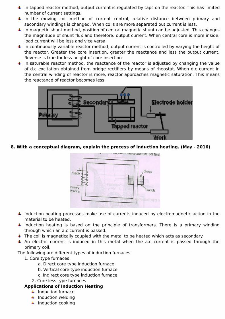
In tapped reactor method, output current is regulated by taps on the reactor. This has limitednumber of current settings.In the moving coil method of current control, relative distance between primary andsecondary windings is changed. When coils are more separated out current is less.In magnetic shunt method, position of central magnetic shunt can be adjusted. This changesthe magnitude of shunt flux and therefore, output current. When central core is more inside,load current will be less and vice versa. In continuously variable reactor method, output current is controlled by varying the height ofthe reactor. Greater the core insertion, greater the reactance and less the output current.Reverse is true for less height of core insertionIn saturable reactor method, the reactance of the reactor is adjusted by changing the valueof d.c excitation obtained from bridge rectifiers by means of rheostat. When d.c current inthe central winding of reactor is more, reactor approaches magnetic saturation. This meansthe reactance of reactor becomes less.
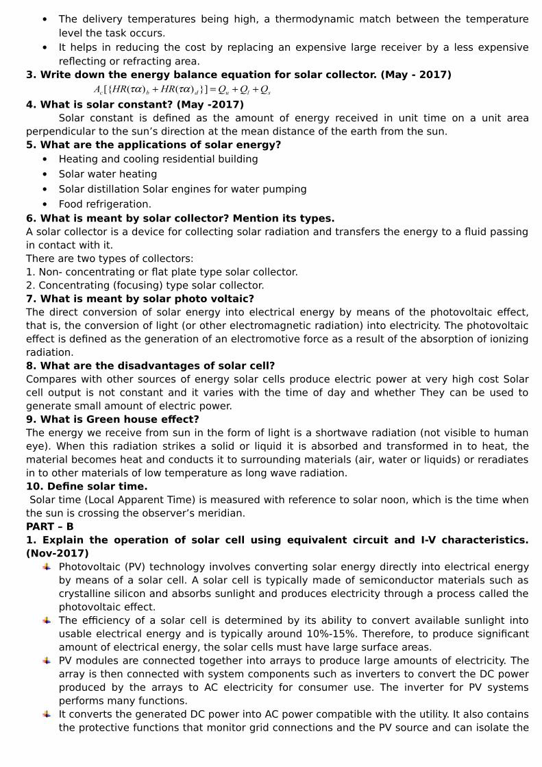
8. With a conceptual diagram, explain the process of induction heating. (May - 2016)
Induction heating processes make use of currents induced by electromagnetic action in thematerial to be heated. Induction heating is based on the principle of transformers. There is a primary windingthrough which an a.c current is passed. The coil is magnetically coupled with the metal to be heated which acts as secondary. An electric current is induced in this metal when the a.c current is passed through theprimary coil.
The following are different types of induction furnaces 1. Core type furnaces
a. Direct core type induction furnace b. Vertical core type induction furnace c. Indirect core type induction furnace
2. Core less type furnacesApplications of Induction Heating
Induction furnace Induction welding Induction cooking

Induction brazing Induction sealing Heat treatment
Advantages of Induction Heating Optimized Consistency Maximized Productivity Improved Product Quality Reduced Energy Consumption
9. Discuss in details about any two types of resistance welding. (Nov - 2014)This method is based upon the I2R loss. Whenever current is passed through a resistive
material heat is produced because of I2 R loss. Direct Resistance Heating:
In this method of heating the material or change to be heated is taken as a resistance andcurrent is passed through it. The charge may be in the form of powder pieces or liquid. The two electrodes are immersedin the charge and connected to the supply. In case of D.C or single phase A.C two electrodes are required but there will be threeelectrodes in case of three phase supply. When metal pieces are to be heated a powder of high resistivity material is sprinkled overthe surface of the charge to avoid direct short circuit. But it gives uniform heat and high temperature. One of the major applications of the processis salt bath furnaces having an operating temperature between 500˚C to 1400˚C. An immersed electrode type medium temperature salt bath furnace is shown in figure The bath makes use of supply voltage across two electrodes varying between 5 to 20 volts. For this purpose a special double wound transformer is required which makes use of 3Фprimary and single phase secondary. This speaks of an unbalanced load. Advantages:
High efficiency. It gives uniform heat and high temperature.
Application: It is mainly used in salt bath furnace and water heaters.
Indirect Resistance Heating:
In this method the current is passed through a highly resistance element which iseither placed above or below the over depending upon the nature of the job to beperformed. The heat proportional to I2R losses produced in heating element delivered to thecharge either by radiation or by convection.

Sometimes in case of industrial heating the resistance is placed in a cylinder which issurrounded by the charge placed in the jackes. The arrangement provides as uniformtemperature. Automatic temperature control can be provided in this case.
Applications This method is used in room heater, in bimetallic strip used in starters, immersion waterheaters and in various types of resistance ovens used in domestic and commercial cooking.
10. Requirement of Heating Materiali) Low Temperature Coefficients of Resistance
Resistance of conducting element varies with the temperature; this variation should be smallin case of an element. Otherwise when switched ON from room temperature to go upto say 1200˚C,the low resistance at initial stage will draw excessively high currents at the same operating voltage.
ii) Resistance coefficient Positive If temperature is negative the element will draw more current when hot. A higher current
means more voltage, a higher temperature or a still lower resistance, which can instability ofoperation. iii) High Melting Point
Its melting point should be sufficiently higher than its operating temperature. Otherwise asmall rise in the operating voltage will destroy the element. iv) High Specific Resistance
The resistivity of the material used for making element should be high. v) High Oxidizing Temperature
Its oxidizing temperature should higher than its operating temperature. To have convenientshapes and sizes, the material used should have high ductility and flexibility. It should not be brittleand fragile. vi) Should with stand Vibration
In most industrial process quite strong vibrations are produced. Some furnaces have to openor rock while hot. The element material should withstand the vibrations while hot and should notbreak open. vii) Mechanical Strength
The material used should have sufficient mechanical strength of its own.
UNIT IV – SOLAR RADIATION AND SOLAR ENERGY COLLECTORSPART - A1. Define collector efficiency. (Nov - 2017)It is defined as the ratio of the energy actually absorbed and transferred to the heat transport fluidby the collector (useful energy) to the energy incident on the collector.2. List the advantage of solar concentrators. (Nov - 2017)
It increases the intensity by concentrating the energy available over a large surface onto asmaller surface (absorber)
Due to concentration on a smaller area, the heat loss area is reduced. Further, the thermalmass us much smaller than that of a flat plate collector and hence transient effects aresmall.
The delivery temperatures being high, a thermodynamic match between the temperaturelevel the task occurs.
It helps in reducing the cost by replacing an expensive large receiver by a less expensivereflecting or refracting area.
3. Write down the energy balance equation for solar collector. (May - 2017)
sludbc QQQHRHRA }])()([{ 4. What is solar constant? (May -2017)
Solar constant is defined as the amount of energy received in unit time on a unit areaperpendicular to the sun’s direction at the mean distance of the earth from the sun.5. What are the applications of solar energy?
Heating and cooling residential building
Solar water heating
Solar distillation Solar engines for water pumping
Food refrigeration.6. What is meant by solar collector? Mention its types. A solar collector is a device for collecting solar radiation and transfers the energy to a fluid passingin contact with it. There are two types of collectors: 1. Non- concentrating or flat plate type solar collector. 2. Concentrating (focusing) type solar collector.7. What is meant by solar photo voltaic? The direct conversion of solar energy into electrical energy by means of the photovoltaic effect,that is, the conversion of light (or other electromagnetic radiation) into electricity. The photovoltaiceffect is defined as the generation of an electromotive force as a result of the absorption of ionizingradiation.8. What are the disadvantages of solar cell? Compares with other sources of energy solar cells produce electric power at very high cost Solarcell output is not constant and it varies with the time of day and whether They can be used togenerate small amount of electric power.9. What is Green house effect? The energy we receive from sun in the form of light is a shortwave radiation (not visible to humaneye). When this radiation strikes a solid or liquid it is absorbed and transformed in to heat, thematerial becomes heat and conducts it to surrounding materials (air, water or liquids) or reradiatesin to other materials of low temperature as long wave radiation.10. Define solar time. Solar time (Local Apparent Time) is measured with reference to solar noon, which is the time whenthe sun is crossing the observer’s meridian.PART – B1. Explain the operation of solar cell using equivalent circuit and I-V characteristics.(Nov-2017)
Photovoltaic (PV) technology involves converting solar energy directly into electrical energyby means of a solar cell. A solar cell is typically made of semiconductor materials such ascrystalline silicon and absorbs sunlight and produces electricity through a process called thephotovoltaic effect. The efficiency of a solar cell is determined by its ability to convert available sunlight intousable electrical energy and is typically around 10%-15%. Therefore, to produce significantamount of electrical energy, the solar cells must have large surface areas.PV modules are connected together into arrays to produce large amounts of electricity. Thearray is then connected with system components such as inverters to convert the DC powerproduced by the arrays to AC electricity for consumer use. The inverter for PV systemsperforms many functions. It converts the generated DC power into AC power compatible with the utility. It also containsthe protective functions that monitor grid connections and the PV source and can isolate the

PV array if grid problems occur. The inverter monitors the terminal conditions of the PVmodule(s) and contains the MPPT for maximizing the energy capture. The MPPT maintains the PV array operation at the highest possible efficiency, over a widerange of input conditions that can vary due to the daily (morning-noon-evening) andseasonal (winter-summer) variations.
Single Phase – Single Stage The most fundamental topology for a PV inverter is a single-phase, self commutated PVsystem as shown in below. The DC output of the PV array is connected across a filtercapacitor. The capacitor is used to limit the harmonic currents in the array. The output of the capacitor connects to a full-bridge converter and the output of theconverter is connected to an inductor, limiting the high frequency harmonics injected intothe AC system. A synthesized AC output voltage is produced by appropriately controlling the switches andconsists of a controlled series of positive and negative pulses that correspond to the positiveand negative half cycles of a sinusoid. The PV array is then connected to the utility grid through an electrical isolation transformer.There are several drawbacks of this topology, one being that all of the modules areconnected to the same MPPT device. This causes severe power losses during partialshadowing.
2. Discuss in detail about the performance of cylindrical and parabolic concentratingcollector. (Nov - 2017)
C=(Effective Aperture Area) / (Absorber Tube Area)C=(W-Do)/(πDo)
DxTTDUrIDWrIdq aplbbbbbbu )()()()( 00
Dqu=Useful heat rate for a length dxρ = Specular reflectivity of the concentractor surfaceᵞ=Intercept factor
The instantaneous collector efficiency ᶯi is given by,
WLrIrI
q
ddbb
ui )(
Ground – Reflected radiation is neglected.
WLrI
q
bb
uib
EffectsPerformance over a day with different tracking modesEffect of inlet temperature

Effect of mass flow rate 3. Explain the basic phenomenon of solar energy conversion with suitable diagram. (May - 2017)Conduction
Thermal conduction is the transfer of heat by the vibrations of atoms, molecules andelectrons without bulk movement. It is the only mechanism of heat transfer in opaque solids, buttransparent media also pass heat energy by radiation. Conduction also occurs in liquids and gases,where, however, heat transfer is usually dominated by convection, as heat is carried by the fluidcirculating or moving in bulk. Consider the heat flow P by conduction through a slab of material,area A, thickness dx, surface temperature difference dT.
dx
dtKAq
RadiationIt is a process by which heat flows from a body at a higher temperature to a body at a lower
temperature when the bodies are separated in space or even a vacuum exists between them. It isthe mode of heat transfer by which the sun transfers energy to the earth.
4TAq Convection
It is a process that transfers heat from one region to another by motion of fluid. The rate ofheat transfer by convection between a surface and a fluid can be calculated from the relation.
)( fscc TTAhq
4. Explain the solar radiation geometry at earth surface. (May - 2017)
Fig shows the Earth as it rotates in 24 h about its own axis, which defines the points of thenorth and south poles N and S. The axis of the poles is normal to the earth’s equatorial plane. C isthe centre of the Earth. The point P on the Earth’s surface is determined by its latitude andlongitude.
Latitude is defined positive for points north of the equator, negative south of the equator. Byinternational agreement longitude is measured positive eastwards from Greenwich, England.1 Thevertical north– south plane through P is the local meridional plane.
Local Apparent Time (LAT) =Standard time +4(Standard time longtitude – Longtitude oflocation) + (Equation of time correction)
AbsorptionScattering
5. What are the main components of a flat plate solar collector, explain the function of each. (May - 2017)
A solar collector is a device for collecting solar radiation by absorbing the energy with thehelp of an absorber. Then the absorbed energy is transferred to a working fluid passing in contactwith it.
Non concentrating – Flat plate Collector

It consist of flat surface with high absorptive for collecting solar radiation, transparentcover, copper tubing and a thermally sealed tight container. Solar radiation first passes through transparent covers and falls on the absorber plate.The absorbed radiation is partly transferred to the working heat transfer fluids passingthrough the tubes.The conduction losses are reduced by using thermal insulation on the back and the edges.
Advantages It uses both beam and diffuses radiationIt needs little maintenance
DisadvantagesEfficiency is lowHeavy heat loss occur
ApplicationsHeating buildingsHeating green houseHeat source for a heat engine
6. What are the merits and demerits of concentrating collectors over a flat plate collector? (May - 2017)
AdvantagesNo fuel costPredictable 24/7 powerNo pollution and global warming effectsUsing existing industrial base
DisadvantagesHigh costsCSP obsoleteWater issueEcological and Cultural IssueIt can focus only direct solar radiation, this performance is poor.
7. Estimation of solar radiationTemperatures of about 107 K and an inner radiation flux of uneven spectraldistribution. This internal radiation is absorbed in the outer passive layers which areheated to about 5800K and so become a source of radiation with a relativelycontinuous spectral distribution. The radiant flux (W/m2) from the Sun at the Earth’s distance varies through the yearby ±4% because of the slightly non-circular path of the Earth around the Sun. Theradiance also varies by perhaps ±0_3 per cent per year due to sunspots; over the lifeof the Earth, there has been probably a natural slow decline of very much less annualsignificance. None of these variations are significant for solar energy applications, for which weconsider extra-terrestrial solar irradiance to be constant.
Figure shows the spectral distribution of the solar irradiance at the Earth’s mean distance,uninfluenced by any atmosphere. Note how similar this distribution is to that from a black bodyat 5800K in shape, peak wavelength and total power emitted.
The area beneath this curve is the solar constant G∗0 = 1367Wm−2. This is the RFDincident on a plane directly facing the Sun and outside the atmosphere at a distanceof 1_496×108 km from the Sun (i.e. at the Earth’s mean distance from the Sun).
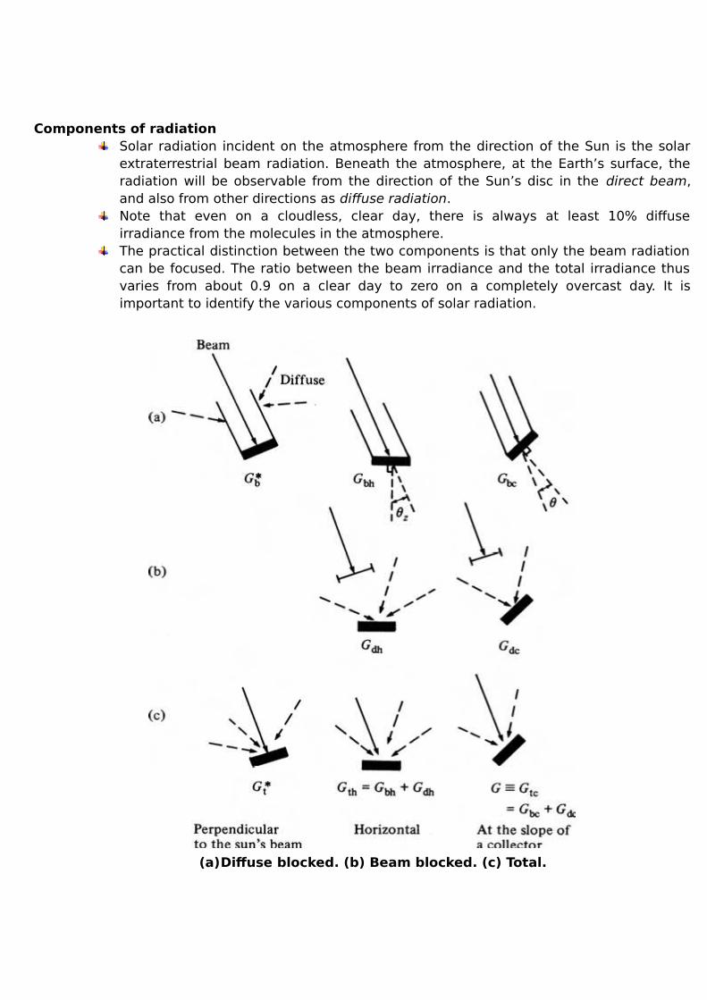
Components of radiationSolar radiation incident on the atmosphere from the direction of the Sun is the solarextraterrestrial beam radiation. Beneath the atmosphere, at the Earth’s surface, theradiation will be observable from the direction of the Sun’s disc in the direct beam,and also from other directions as diffuse radiation. Note that even on a cloudless, clear day, there is always at least 10% diffuseirradiance from the molecules in the atmosphere. The practical distinction between the two components is that only the beam radiationcan be focused. The ratio between the beam irradiance and the total irradiance thusvaries from about 0.9 on a clear day to zero on a completely overcast day. It isimportant to identify the various components of solar radiation.
(a)Diffuse blocked. (b) Beam blocked. (c) Total.

UNIT V – WIND ENERGYPART - A1. What are the causes of aerodynamic force? (Nov - 2017)
The normal force due to the pressure on the surface of the body
The shear force due to the viscosity of the gas, also known as skin friction.2. List the factors responsible for distribution of wind energy on the surface of earth.(Nov - 2017)
Atmospheric Pressure
Coriolis Effect
Topography3. Write down the condition for maximum power generation in wind energy conversionsystem. (May- 2017)
0230 2 ieiee
VVVVdV
dP
4. List the types of wind turbines. (May - 2017) Horizontal-axis turbines. Vertical-axis turbines.
5. Define power coefficient The fraction of the free flow wind power that can be extracted by a rotor is called the power-coefficient.
Power coefficient = Power of wind turbine/Power available in the wind6. Name the characteristics in which the speed of a wind turbine rotor depends.The speed of a wind turbine rotor depends principally on Wind speed Pitch of the turbine bladesMechanical and electrical load i.e., shaft load, friction, breaking force etc., Orientation of yaw withreference to the wind.7. What are the main Environmental aspects due to wind turbines? The mainenvironmental aspects are:
Indirect energy use and emissions
Bird life
Noise
Visual impact
Telecommunication interference
Safety
Effects on ecosystem8. What are the types of wind power plants?
Remote
Hybrid
Grid connected system.9. What are the advantages of wind energy systems?
Inexhaustible fuel source
No pollution
Often an excellent supplement to other renewable sources
Reduces fossil fuel consumption
Wind power plant create may jobs
Increases local tax revenues
10. What are the disadvantages of wind energy systems? Large areas are needed
Suitable for wind power generation
Relatively expensive to maintain
Large numbers of wind generators are required to produce useful amount of heat orelectricity.
PART – B1. Give some important factors that are considered for site selection of WECS. (May -2017)
Four typesPlain land sitesHill top sitesSea shores sitesOff shore shallow water sites
It is important to consider the technical, environmental, social, economic and other factorsbefore erecting the wind energy conversion system.As the building, forest offers the resistance to the air movement; the wind mills are locatedaway from cities and forest.As the wind velocities are high in flat open area, plain land sites should be selected.Ground surface should be stable.If small trees, grass or vegetation are present then the height of the tower will increase,which increase the cost of the system.Approach roads up to site for the movement of erection equipments structures, materials,blades.Site selected should be nearer to the customer, which minimizes the cost and losses.Cost of the land for the site should be favourable.Other conditions such as icing problem, salt spray or blowing dust should not present at theselected site. Because they may affect the turbine blades.The site selected should have adequate and uniform average wind velocity throughout year.Altitude of the proposed site should be considered.
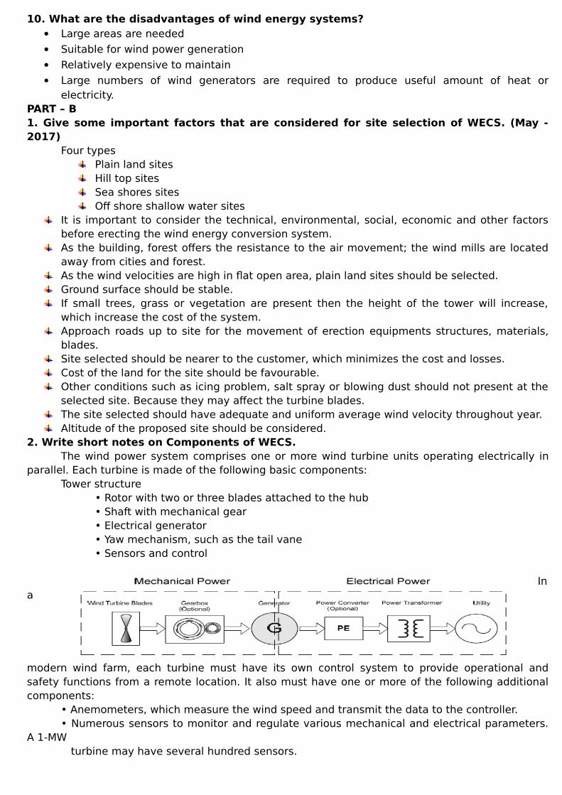
2. Write short notes on Components of WECS.The wind power system comprises one or more wind turbine units operating electrically in
parallel. Each turbine is made of the following basic components:Tower structure
• Rotor with two or three blades attached to the hub• Shaft with mechanical gear• Electrical generator• Yaw mechanism, such as the tail vane• Sensors and control
Ina
modern wind farm, each turbine must have its own control system to provide operational andsafety functions from a remote location. It also must have one or more of the following additionalcomponents:
• Anemometers, which measure the wind speed and transmit the data to the controller.• Numerous sensors to monitor and regulate various mechanical and electrical parameters.
A 1-MW turbine may have several hundred sensors.
• Stall controller, which starts the machine at set wind speeds of 8 to 15 mph and shuts offat 50 to 70 mph to protect the blades from overstressing and the generator from overheating.• Power electronics to convert and condition power to the required standards.• Control electronics, usually incorporating a computer.• Battery for improving load availability in a stand-alone plant.• Transmission link for connecting the plant to the area grid.
The following are commonly used terms and terminology in the wind power industry:Low-speed shaft: The rotor turns the low-speed shaft at 30 to 60 rotations per minute (rpm).High-speed shaft: It drives the generator via a speed step-up gear.Brake: A disc brake, which stops the rotor in emergencies. It can be applied mechanically,electrically, or hydraulically.Gearbox: Gears connect the low-speed shaft to the high-speed shaft and increase the turbinespeed from 30 to 60 rpm to the 1200 to 1800 rpm required by most generators to produceelectricity in an efficient manner. Because the gearbox is a costly and heavy part, design engineersare exploring slow speed, direct-drive generators that need no gearbox.Generator: It is usually an off-the-shelf induction generator that produces 50- or 60-Hz AC power.Nacelle: The rotor attaches to the nacelle, which sits atop the tower and includes a gearbox, low-and high-speed shafts, generator, controller, and a brake. A cover protects the components insidethe nacelle. Some nacelles are large enough for technicians to stand inside while working.3. Explain in detail about different Types of Wind Turbines
The wind turbine captures the wind’s kinetic energy in a rotor consisting of two ormore blades mechanically coupled to an electrical generator. The turbine is mountedon a tall tower to enhance the energy capture. Numerous wind turbines are installedat one site to build a wind farm of the desired power generation capacity. Obviously, sites with steady high wind produce more energy over the year. Twodistinctly different configurations are available for turbine design, the horizontal axisconfiguration and the vertical-axis configuration.
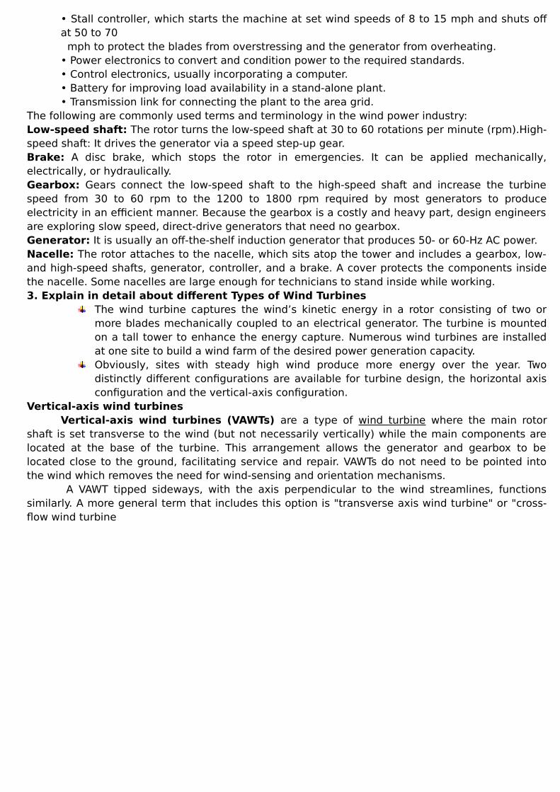
Vertical-axis wind turbinesVertical-axis wind turbines (VAWTs) are a type of wind turbine where the main rotor
shaft is set transverse to the wind (but not necessarily vertically) while the main components arelocated at the base of the turbine. This arrangement allows the generator and gearbox to belocated close to the ground, facilitating service and repair. VAWTs do not need to be pointed intothe wind which removes the need for wind-sensing and orientation mechanisms.
A VAWT tipped sideways, with the axis perpendicular to the wind streamlines, functionssimilarly. A more general term that includes this option is "transverse axis wind turbine" or "cross-flow wind turbine
Advantages They are omni-directional and do not need to track the wind. This means they don't require a
complex mechanism and motors to yaw the rotor and pitch the blades. Ability to take advantage of turbulent and gusty winds. Such winds are not harvested by
HAWTs, and in fact cause accelerated fatigue for HAWTs. Wings of the Darrieus type have a constant chord and so are easier to manufacture than the
blades of a HAWT, which have a much more complex shape and structure. Can be grouped more closely in wind farms, increasing the generated power per unit of land
area. Can be installed on a wind farm below the existing HAWTs; this will improve the efficiency
(power output) of the existing farm.DisadvantagesOne of the major outstanding challenges facing vertical axis wind turbine technology is dynamicstall of the blades as the angle of attack varies rapidly.
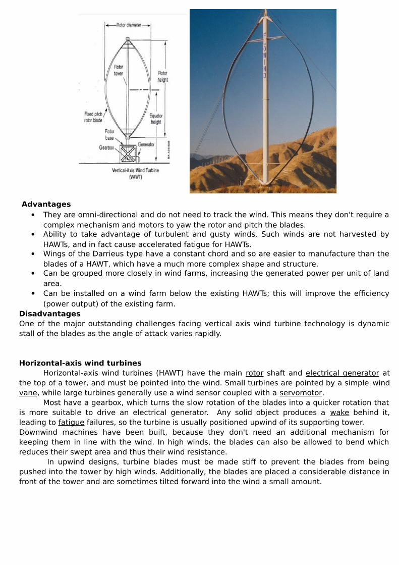
Horizontal-axis wind turbinesHorizontal-axis wind turbines (HAWT) have the main rotor shaft and electrical generator at
the top of a tower, and must be pointed into the wind. Small turbines are pointed by a simple windvane, while large turbines generally use a wind sensor coupled with a servomotor.
Most have a gearbox, which turns the slow rotation of the blades into a quicker rotation thatis more suitable to drive an electrical generator. Any solid object produces a wake behind it,leading to fatigue failures, so the turbine is usually positioned upwind of its supporting tower. Downwind machines have been built, because they don't need an additional mechanism forkeeping them in line with the wind. In high winds, the blades can also be allowed to bend whichreduces their swept area and thus their wind resistance.
In upwind designs, turbine blades must be made stiff to prevent the blades from beingpushed into the tower by high winds. Additionally, the blades are placed a considerable distance infront of the tower and are sometimes tilted forward into the wind a small amount.
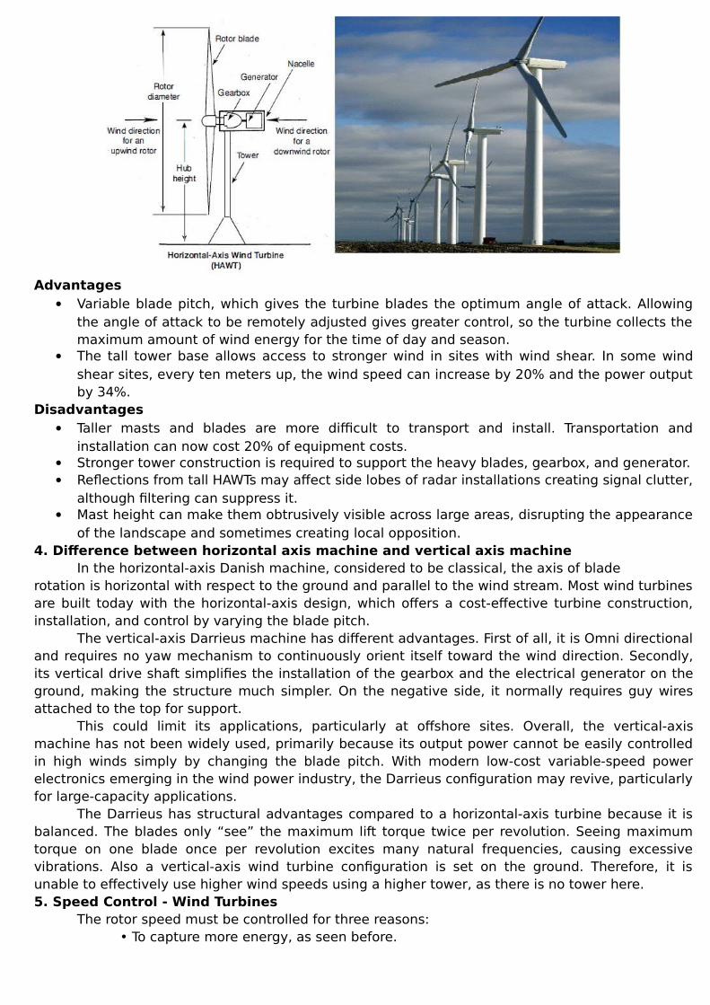
Advantages Variable blade pitch, which gives the turbine blades the optimum angle of attack. Allowing
the angle of attack to be remotely adjusted gives greater control, so the turbine collects themaximum amount of wind energy for the time of day and season.
The tall tower base allows access to stronger wind in sites with wind shear. In some windshear sites, every ten meters up, the wind speed can increase by 20% and the power outputby 34%.
Disadvantages Taller masts and blades are more difficult to transport and install. Transportation and
installation can now cost 20% of equipment costs. Stronger tower construction is required to support the heavy blades, gearbox, and generator. Reflections from tall HAWTs may affect side lobes of radar installations creating signal clutter,
although filtering can suppress it. Mast height can make them obtrusively visible across large areas, disrupting the appearance
of the landscape and sometimes creating local opposition.4. Difference between horizontal axis machine and vertical axis machine
In the horizontal-axis Danish machine, considered to be classical, the axis of bladerotation is horizontal with respect to the ground and parallel to the wind stream. Most wind turbinesare built today with the horizontal-axis design, which offers a cost-effective turbine construction,installation, and control by varying the blade pitch.
The vertical-axis Darrieus machine has different advantages. First of all, it is Omni directionaland requires no yaw mechanism to continuously orient itself toward the wind direction. Secondly,its vertical drive shaft simplifies the installation of the gearbox and the electrical generator on theground, making the structure much simpler. On the negative side, it normally requires guy wiresattached to the top for support.
This could limit its applications, particularly at offshore sites. Overall, the vertical-axismachine has not been widely used, primarily because its output power cannot be easily controlledin high winds simply by changing the blade pitch. With modern low-cost variable-speed powerelectronics emerging in the wind power industry, the Darrieus configuration may revive, particularlyfor large-capacity applications.
The Darrieus has structural advantages compared to a horizontal-axis turbine because it isbalanced. The blades only “see” the maximum lift torque twice per revolution. Seeing maximumtorque on one blade once per revolution excites many natural frequencies, causing excessivevibrations. Also a vertical-axis wind turbine configuration is set on the ground. Therefore, it isunable to effectively use higher wind speeds using a higher tower, as there is no tower here.5. Speed Control - Wind Turbines
The rotor speed must be controlled for three reasons:• To capture more energy, as seen before.
• To protect the rotor, generator, and power electronic equipment from overloadingduring high-gust winds.• When the generator is disconnected from the electrical load, accidentally or for a
scheduled event. Under this condition, the rotor speed may run away, destroying it
mechanically, if it is not controlled.
The speed control requirement of the rotor has five separate regions:1. The cut-in speed at which the turbine starts producing power. Below this speed, it is notworthwhile, nor efficient, to turn the turbine on.2. The constant maximum Cp region where the rotor speed varies with the wind speed variation tooperate at the constant TSR corresponding to the maximum Cp value.3. During high winds, the rotor speed is limited to an upper constant limit based on the design limitof the system components. In the constant-speed region, the Cp is lower than the maximum Cp,and the power increases at a lower rate than that in the first region.4. At still higher wind speeds, such as during a gust, the machine is operated at a controlledconstant power to protect the generator and power electronics from overloading. This can beachieved by lowering the rotor speed. If the speed is decreased by increasing the electrical load,then the generator will be overloaded, defeating the purpose. To avoid generator overloading,some sort of a brake (eddy current or another type) must be installed on the rotor.5. The cut out speed, at which the rotor is shut off to protect the blades, the electrical generator,and other components of the system beyond a certain wind speed.6. Explain wind energy conversion system with neat schematic diagram.
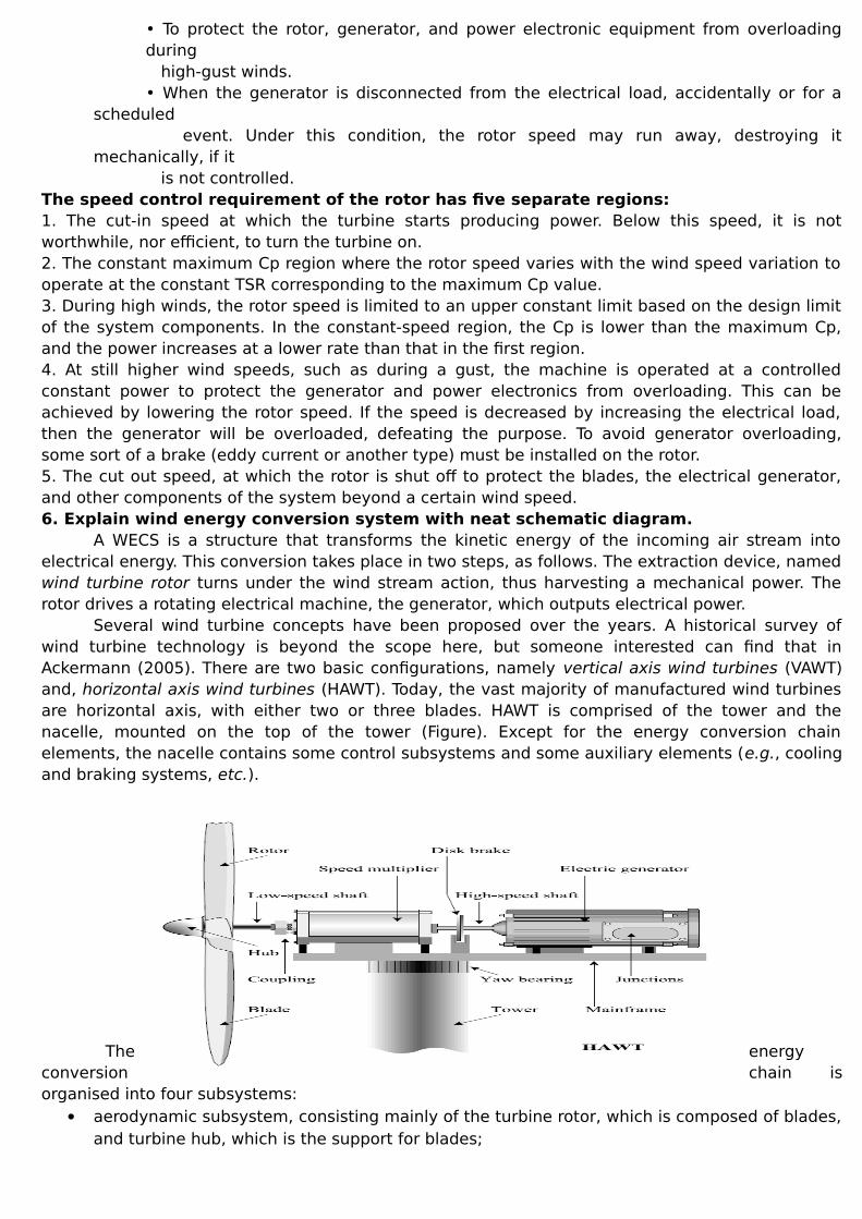
A WECS is a structure that transforms the kinetic energy of the incoming air stream intoelectrical energy. This conversion takes place in two steps, as follows. The extraction device, namedwind turbine rotor turns under the wind stream action, thus harvesting a mechanical power. Therotor drives a rotating electrical machine, the generator, which outputs electrical power.
Several wind turbine concepts have been proposed over the years. A historical survey ofwind turbine technology is beyond the scope here, but someone interested can find that inAckermann (2005). There are two basic configurations, namely vertical axis wind turbines (VAWT)and, horizontal axis wind turbines (HAWT). Today, the vast majority of manufactured wind turbinesare horizontal axis, with either two or three blades. HAWT is comprised of the tower and thenacelle, mounted on the top of the tower (Figure). Except for the energy conversion chainelements, the nacelle contains some control subsystems and some auxiliary elements (e.g., coolingand braking systems, etc.).
The energyconversion chain isorganised into four subsystems:
aerodynamic subsystem, consisting mainly of the turbine rotor, which is composed of blades,and turbine hub, which is the support for blades;
drive train, generally composed of: low-speed shaft – coupled with the turbine hub, speed multiplier and high-speed shaft – driving the electrical generator; electromagnetic subsystem, consisting mainly of the electric generator; Electric subsystem, including the elements for grid connection and local grid.
All wind turbines have a mechanism that moves the nacelle such that the blades mareperpendicular to the wind direction. This mechanism could be a tail vane (small wind turbines) oran electric yaw device (medium and large wind turbines). Concerning the power conversion chain,it involves naturally some loss of power. Because of the nonzero wind velocity behind the windturbine rotor one can easily understand that its efficiency is less than unity. Also, depending on theoperating regime, both the motion transmission and the electrical power generation involve lossesby friction and by Joule effect respectively. Being directly coupled one with the other, the energyconversion chain elements dynamically interact, mutually influencing their operation.7. Derive the expression for the Forces acting on the blades and thrust on turbines
There are two types of forces which are acting on the blades. They are, circumferential forceacting in the direction of wheel rotation that provides the torque and axial force acting in thedirection of the wind stream that provides an axial thrust that must be counteracted by propermechanical design.
DN
PPT
Where T – Torque (Nm)ω– Angular Velocity of turbine wheel (m/s)D – Diameter of turbine wheel (m)
AD4
N-Wheel of revolution per unit time (S^-1)
totalPP
22max 9 i
cx VD
gF
8. Performance of wind machinesThe overall conversion efficiency Ƞ0 = (Useful output power)/(Wind power output) =
ȠA*ȠG*ȠC*ȠGen
Where ȠA=Efficiency of the aero turbineȠG=Efficiency of gearingȠC=Efficiency of the mechanical coupling ȠGen=Efficiency of the generatorȠA=(Useful shaft power output)/(Wind power input)=CP=Coefficient of performance
9. Speed and power relation – WindThe kinetic energy in air of mass m moving with speed V is given by the following in joules:
The power in moving air is the flow rate of kinetic energy per second in watts:
IfP= mechanical power in the moving air (watts),ρ = air density (kg/m3),A= area swept by the rotor blades (m2), andV= velocity of the air (m/sec),

Then the volumetric flow rate is AV, the mass flow rate of the air in kilograms per second isρAV, and the mechanical power coming in the upstream wind is given by the following in watts:
Two potential wind sites are compared in terms of the specific wind power expressed in wattsper square meter of area swept by the rotating blades. It is also referred to as the power density ofthe site, and is given by the following expression in watts per square meter of the rotor-swept area:
This is the power in the upstream wind. It varies linearly with the density of the air sweepingthe blades and with the cube of the wind speed. The blades cannot extract all of the upstream windpower, as some power is left in the downstream air that continues to move with reduced speed.POWER EXTRACTED FROM THE WIND
The actual power extracted by the rotor blades is the difference between the upstream anddownstream wind powers. Using Equation 3.2, this is given by the following equation in units ofwatts:
wherePo= mechanical power extracted by the rotor, i.e., the turbine output power,V= upstream wind velocity at the entrance of the rotor blades, andVo= downstream wind velocity at the exit of the rotor blades.
The mechanical power extracted by the rotor, which drives the electrical generator, is therefore:

The preceding expression is algebraically rearranged in the following form:
The power extracted by the blades is customarily expressed as a fraction of the upstream windpower in watts as follows:
Where
Comparing Equations, we can say that Cp is the fraction of the upstream wind power that is
extracted by the rotor blades and fed to the electrical generator. The remaining power is dissipatedin the downstream wind. The factor Cp is called the power coefficient of the rotor or the rotorefficiency.
Figure: typical characteristics of wind energy conversion systemAdvantages of Wind Energy
It is a free source of energy

Produces no water or air pollution Wind farms are relatively inexpensive to build Land around wind farms can have other uses
Disadvantages of Wind Energy Requires constant and significant amounts of wind Wind farms require significant amounts of land Can have a significant visual impact on landscapes