UNIT 5 LINEAR MEASURING DEVICES AND Linear Measuring ...
20
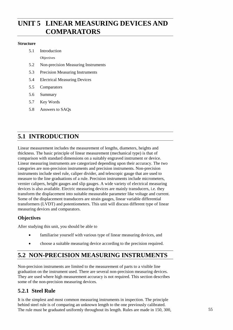
55 UNIT 5 LINEAR MEASURING DEVICES AND COMPARATORS Structure 5.1 Introduction Objectives 5.2 Non-precision Measuring Instruments 5.3 Precision Measuring Instruments 5.4 Electrical Measuring Devices 5.5 Comparators 5.6 Summary 5.7 Key Words 5.8 Answers to SAQs 5.1 INTRODUCTION Linear measurement includes the measurement of lengths, diameters, heights and thickness. The basic principle of linear measurement (mechanical type) is that of comparison with standard dimensions on a suitably engraved instrument or device. Linear measuring instruments are categorized depending upon their accuracy. The two categories are non-precision instruments and precision instruments. Non-precision instruments include steel rule, caliper divider, and telescopic gauge that are used to measure to the line graduations of a rule. Precision instruments include micrometers, vernier calipers, height gauges and slip gauges. A wide variety of electrical measuring devices is also available. Electric measuring devices are mainly transducers, i.e. they transform the displacement into suitable measurable parameter like voltage and current. Some of the displacement transducers are strain gauges, linear variable differential transformers (LVDT) and potentiometers. This unit will discuss different type of linear measuring devices and comparators. Objectives After studying this unit, you should be able to familiarise yourself with various type of linear measuring devices, and choose a suitable measuring device according to the precision required. 5.2 NON-PRECISION MEASURING INSTRUMENTS Non-precision instruments are limited to the measurement of parts to a visible line graduation on the instrument used. There are several non-precision measuring devices. They are used where high measurement accuracy is not required. This section describes some of the non-precision measuring devices. 5.2.1 Steel Rule It is the simplest and most common measuring instruments in inspection. The principle behind steel rule is of comparing an unknown length to the one previously calibrated. The rule must be graduated uniformly throughout its length. Rules are made in 150, 300,
Transcript of UNIT 5 LINEAR MEASURING DEVICES AND Linear Measuring ...
55
Linear Measuring Devices
and Comparators UNIT 5 LINEAR MEASURING DEVICES AND
COMPARATORS
Structure
5.1 Introduction
Objectives
5.2 Non-precision Measuring Instruments
5.3 Precision Measuring Instruments
5.4 Electrical Measuring Devices
5.5 Comparators
5.6 Summary
5.7 Key Words
5.8 Answers to SAQs
5.1 INTRODUCTION
Linear measurement includes the measurement of lengths, diameters, heights and
thickness. The basic principle of linear measurement (mechanical type) is that of
comparison with standard dimensions on a suitably engraved instrument or device.
Linear measuring instruments are categorized depending upon their accuracy. The two
categories are non-precision instruments and precision instruments. Non-precision
instruments include steel rule, caliper divider, and telescopic gauge that are used to
measure to the line graduations of a rule. Precision instruments include micrometers,
vernier calipers, height gauges and slip gauges. A wide variety of electrical measuring
devices is also available. Electric measuring devices are mainly transducers, i.e. they
transform the displacement into suitable measurable parameter like voltage and current.
Some of the displacement transducers are strain gauges, linear variable differential
transformers (LVDT) and potentiometers. This unit will discuss different type of linear
measuring devices and comparators.
Objectives
After studying this unit, you should be able to
familiarise yourself with various type of linear measuring devices, and
choose a suitable measuring device according to the precision required.
5.2 NON-PRECISION MEASURING INSTRUMENTS
Non-precision instruments are limited to the measurement of parts to a visible line
graduation on the instrument used. There are several non-precision measuring devices.
They are used where high measurement accuracy is not required. This section describes
some of the non-precision measuring devices.
5.2.1 Steel Rule
It is the simplest and most common measuring instruments in inspection. The principle
behind steel rule is of comparing an unknown length to the one previously calibrated.
The rule must be graduated uniformly throughout its length. Rules are made in 150, 300,
56
Metrology and
Instrumentation 500 and 1000 mm length. There are rules that have got some attachment and special
features with them to make their use more versatile. They may be made in folded form so
that they can be kept in pockets. The degree of accuracy when measurements are made
by a steel rule depends upon the quality of the rule, and the skill of the user in estimating
part of a millimeter.
5.2.2 Calipers
Calipers are used for measurement of the parts, which cannot be measured directly with
the scale. Thus, they are accessories to scales. The calipers consist of two legs hinged at
top, and the ends of legs span part to be inspected. This span is maintained and
transferred to the scale. Calipers are of two types : spring type and firm joint type.
Spring Type
As the name explains, the two legs are attached with spring in this type of calipers.
The working ends of each leg of a spring calipers should be identical in shape and
have contact points equally distant from the fulcrum. The cross-section of the legs
is either rectangular or circular in shape. The calipers are adjusted to set
dimensions by means of either a knurled solid nut or a knurled quick action
release nut operating in a finely threaded adjusting screw. The top portion of the
legs are located in a flanged fulcrum roller and held in position by a spring in
order to maintain the alignment of the working ends. The spring provides
sufficient tension to hold the legs rigid at all points of the adjustment. A separate
washer under the nut minimizes the friction between the adjusting nut and the leg.
Spring type calipers are of following types :
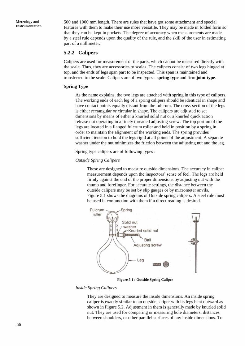
Outside Spring Calipers
These are designed to measure outside dimensions. The accuracy in caliper
measurement depends upon the inspectors’ sense of feel. The legs are held
firmly against the end of the proper dimensions by adjusting nut with the
thumb and forefinger. For accurate settings, the distance between the
outside calipers may be set by slip gauges or by micrometer anvils.
Figure 5.1 shows the diagrams of Outside spring calipers. A steel rule must
be used in conjunction with them if a direct reading is desired.
Figure 5.1 : Outside Spring Caliper
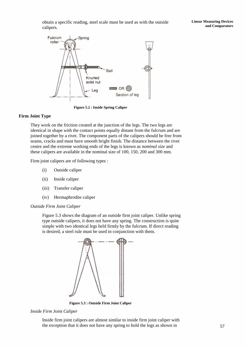
Inside Spring Calipers
They are designed to measure the inside dimensions. An inside spring
caliper is exactly similar to an outside caliper with its legs bent outward as
shown in Figure 5.2. Adjustment in them is generally made by knurled solid
nut. They are used for comparing or measuring hole diameters, distances
between shoulders, or other parallel surfaces of any inside dimensions. To
57
Linear Measuring Devices
and Comparators obtain a specific reading, steel scale must be used as with the outside
calipers.
Figure 5.2 : Inside Spring Caliper
Firm Joint Type
They work on the friction created at the junction of the legs. The two legs are
identical in shape with the contact points equally distant from the fulcrum and are
joined together by a rivet. The component parts of the calipers should be free from
seams, cracks and must have smooth bright finish. The distance between the rivet
centre and the extreme working ends of the legs is known as nominal size and
these calipers are available in the nominal size of 100, 150, 200 and 300 mm.
Firm joint calipers are of following types :
(i) Outside caliper
(ii) Inside caliper
(iii) Transfer caliper
(iv) Hermaphrodite caliper
Outside Firm Joint Caliper
Figure 5.3 shows the diagram of an outside firm joint caliper. Unlike spring
type outside calipers, it does not have any spring. The construction is quite
simple with two identical legs held firmly by the fulcrum. If direct reading
is desired, a steel rule must be used in conjunction with them.
Figure 5.3 : Outside Firm Joint Caliper
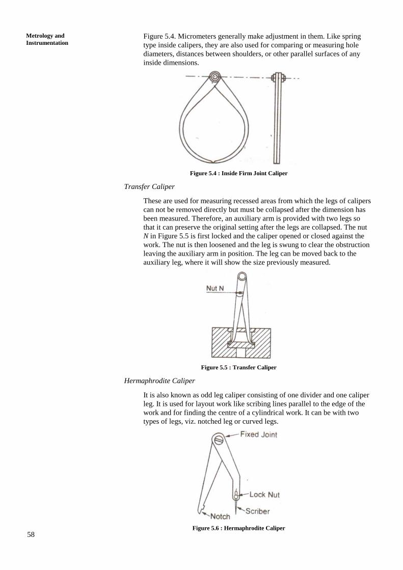
Inside Firm Joint Caliper
Inside firm joint calipers are almost similar to inside firm joint caliper with
the exception that it does not have any spring to hold the legs as shown in
58
Metrology and
Instrumentation Figure 5.4. Micrometers generally make adjustment in them. Like spring
type inside calipers, they are also used for comparing or measuring hole
diameters, distances between shoulders, or other parallel surfaces of any
inside dimensions.
Figure 5.4 : Inside Firm Joint Caliper
Transfer Caliper
These are used for measuring recessed areas from which the legs of calipers
can not be removed directly but must be collapsed after the dimension has
been measured. Therefore, an auxiliary arm is provided with two legs so
that it can preserve the original setting after the legs are collapsed. The nut
N in Figure 5.5 is first locked and the caliper opened or closed against the
work. The nut is then loosened and the leg is swung to clear the obstruction
leaving the auxiliary arm in position. The leg can be moved back to the
auxiliary leg, where it will show the size previously measured.
Figure 5.5 : Transfer Caliper
Hermaphrodite Caliper
It is also known as odd leg caliper consisting of one divider and one caliper
leg. It is used for layout work like scribing lines parallel to the edge of the
work and for finding the centre of a cylindrical work. It can be with two
types of legs, viz. notched leg or curved legs.
Figure 5.6 : Hermaphrodite Caliper
59
Linear Measuring Devices
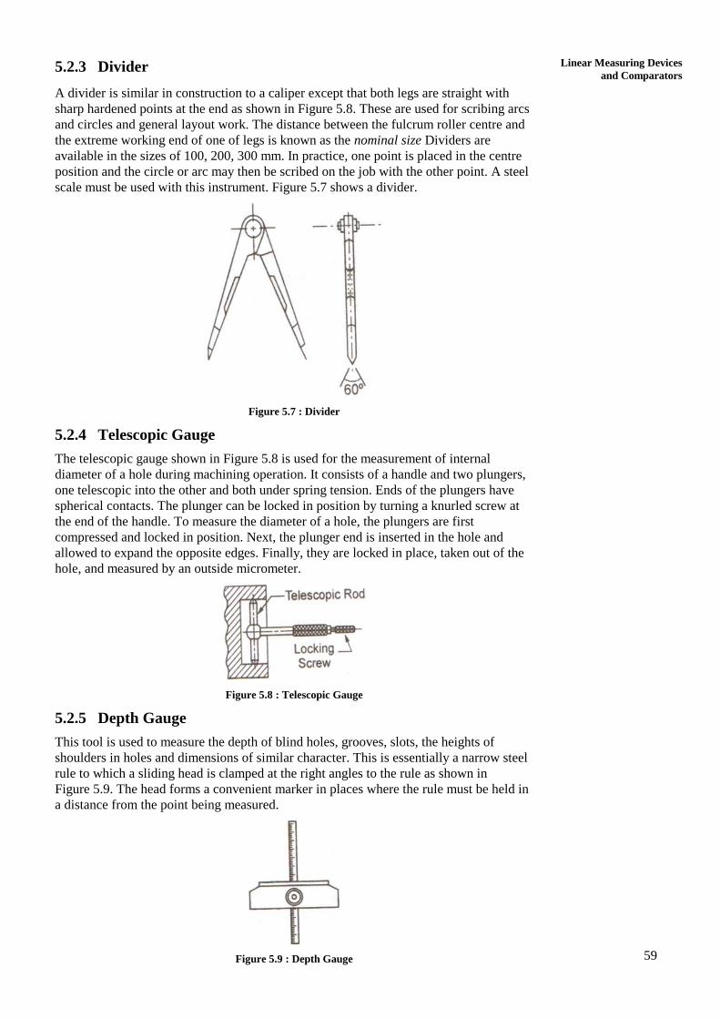
and Comparators 5.2.3 Divider
A divider is similar in construction to a caliper except that both legs are straight with
sharp hardened points at the end as shown in Figure 5.8. These are used for scribing arcs
and circles and general layout work. The distance between the fulcrum roller centre and
the extreme working end of one of legs is known as the nominal size Dividers are
available in the sizes of 100, 200, 300 mm. In practice, one point is placed in the centre
position and the circle or arc may then be scribed on the job with the other point. A steel
scale must be used with this instrument. Figure 5.7 shows a divider.
Figure 5.7 : Divider
5.2.4 Telescopic Gauge
The telescopic gauge shown in Figure 5.8 is used for the measurement of internal
diameter of a hole during machining operation. It consists of a handle and two plungers,
one telescopic into the other and both under spring tension. Ends of the plungers have
spherical contacts. The plunger can be locked in position by turning a knurled screw at
the end of the handle. To measure the diameter of a hole, the plungers are first
compressed and locked in position. Next, the plunger end is inserted in the hole and
allowed to expand the opposite edges. Finally, they are locked in place, taken out of the
hole, and measured by an outside micrometer.
Figure 5.8 : Telescopic Gauge
5.2.5 Depth Gauge
This tool is used to measure the depth of blind holes, grooves, slots, the heights of
shoulders in holes and dimensions of similar character. This is essentially a narrow steel
rule to which a sliding head is clamped at the right angles to the rule as shown in
Figure 5.9. The head forms a convenient marker in places where the rule must be held in
a distance from the point being measured.
Figure 5.9 : Depth Gauge
60
Metrology and
Instrumentation 5.3 PRECISION MEASURING INSTRUMENTS
Since modern production processes is concerned with interchangeable products, precise
dimensional control is required in industry. Precision measurement instruments use
different techniques and phenomena to measure distance with accuracy. We will discuss
some of the precision measuring instruments in this section.
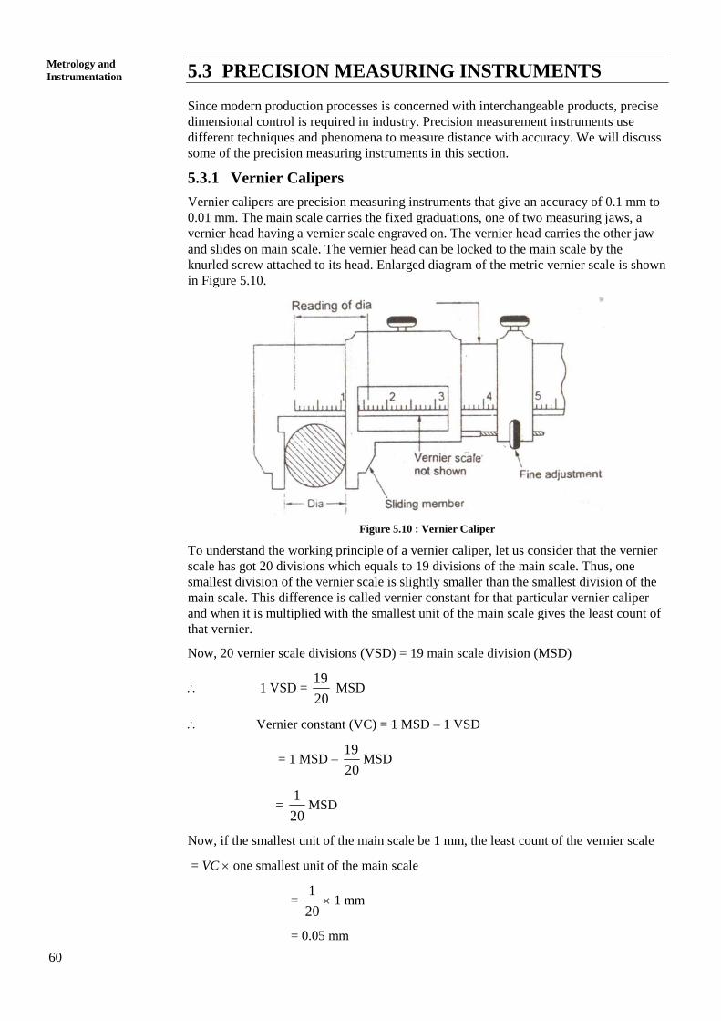
5.3.1 Vernier Calipers
Vernier calipers are precision measuring instruments that give an accuracy of 0.1 mm to
0.01 mm. The main scale carries the fixed graduations, one of two measuring jaws, a
vernier head having a vernier scale engraved on. The vernier head carries the other jaw
and slides on main scale. The vernier head can be locked to the main scale by the
knurled screw attached to its head. Enlarged diagram of the metric vernier scale is shown
in Figure 5.10.
Figure 5.10 : Vernier Caliper
To understand the working principle of a vernier caliper, let us consider that the vernier
scale has got 20 divisions which equals to 19 divisions of the main scale. Thus, one
smallest division of the vernier scale is slightly smaller than the smallest division of the
main scale. This difference is called vernier constant for that particular vernier caliper
and when it is multiplied with the smallest unit of the main scale gives the least count of
that vernier.
Now, 20 vernier scale divisions (VSD) = 19 main scale division (MSD)
1 VSD = 20
19 MSD
Vernier constant (VC) = 1 MSD – 1 VSD
= 1 MSD – 20
19MSD
= 20
1MSD
Now, if the smallest unit of the main scale be 1 mm, the least count of the vernier scale
= VC one smallest unit of the main scale
= 20
1 1 mm
= 0.05 mm
61
Linear Measuring Devices
and Comparators If the smallest unit in the main scale be 0.5 mm, the least count of the vernier scale is,
= 20
1 0.5 mm
= 0.025 mm
To read a measurement from a vernier caliper, first the main scale reading up to the zero
of the vernier scale is noted down. It will give accuracy up to the smallest division of the
main scale. Now, vernier number of vernier scale division from its zero, which coincides
exactly with the main scale is noted. This number when multiplied with the vernier
constant gives the vernier scale reading. The actual length is obtained when the vernier
scale reading is added to the main scale reading.
The caliper is placed on the object to be measured and the fine adjustment screw is
adjusted until the jaws tightly fit against the Workpiece. There are vernier calipers that
incorporate arrangements for measurement of internal dimensions and depth. The vernier
calipers are designed to measure both internal and external dimensions. The lower jaws
of a vernier scale are used for external measurement and the upper jaws for the
measurement of internal dimensions. The rectangular rod carried by the movable jaw is
used for the measurement of depth.
SAQ 1
(a) Describe different types of caliper for measuring the linear dimensions.
(b) A vernier scale consists of 25 divisions on 12 mm spacing and the main
scale has 24 divisions on 12 mm. What is the least count?
5.3.2 Micrometers
Micrometer is one of the most widely used precision instruments. It is primarily used to
measure external dimensions like diameters of shafts, thickness of parts etc. to an
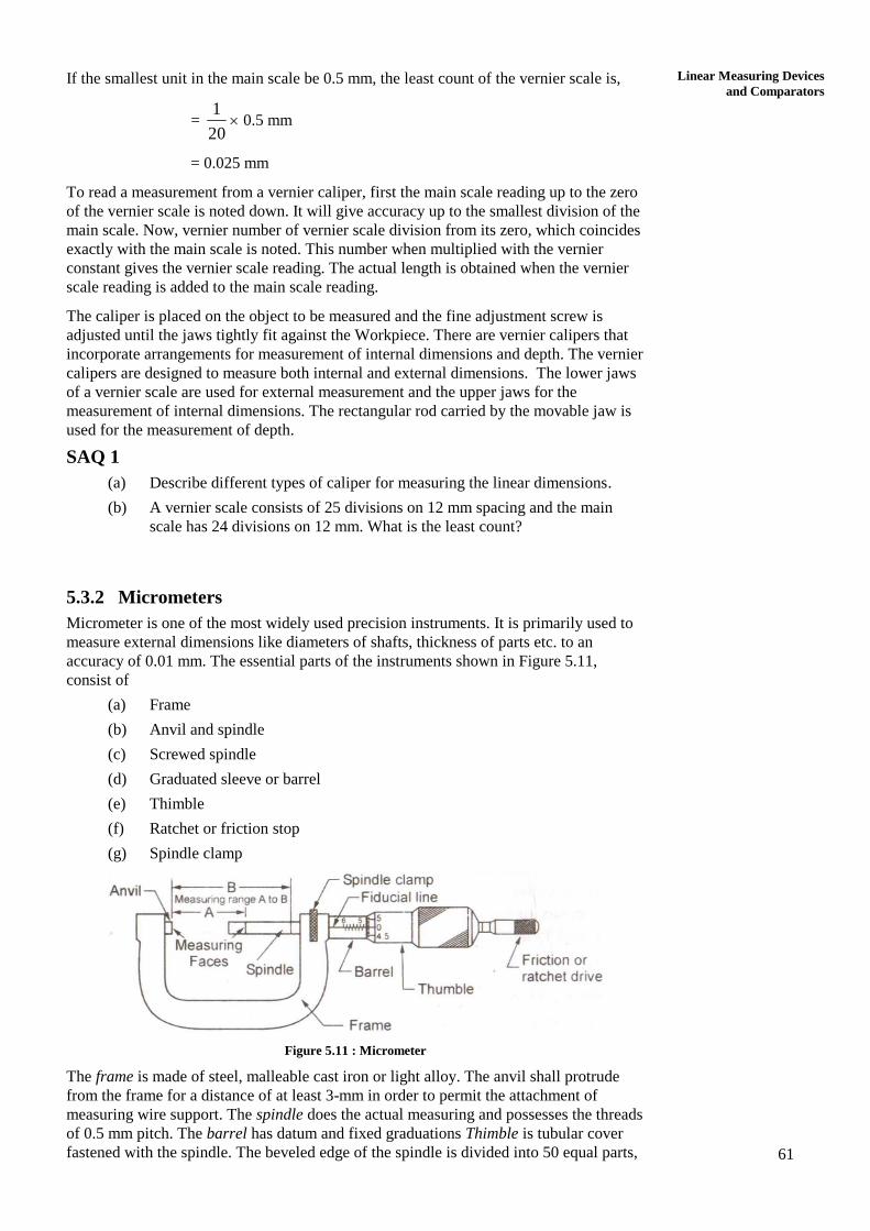
accuracy of 0.01 mm. The essential parts of the instruments shown in Figure 5.11,
consist of
(a) Frame
(b) Anvil and spindle
(c) Screwed spindle
(d) Graduated sleeve or barrel
(e) Thimble
(f) Ratchet or friction stop
(g) Spindle clamp
Figure 5.11 : Micrometer
The frame is made of steel, malleable cast iron or light alloy. The anvil shall protrude
from the frame for a distance of at least 3-mm in order to permit the attachment of
measuring wire support. The spindle does the actual measuring and possesses the threads
of 0.5 mm pitch. The barrel has datum and fixed graduations Thimble is tubular cover
fastened with the spindle. The beveled edge of the spindle is divided into 50 equal parts,
62
Metrology and
Instrumentation every fifth being numbered. The ratchet is a small extension to the thimble. It slips when
the pressure on the screw exceeds a certain amount. It produces uniform reading and
prevents damage or distortion of the instruments. The spindle clamp is used to lock the
instrument at any desired setting.
Procedure for Reading in a Micrometer
The graduation on the barrel is in two parts divided by a line along the axis of the
barrel called the reference line. The graduation above the reference is graduated in
1 mm intervals. The first and every fifth are long and numbered 0, 5, 10, 15, etc.
The lower graduations are marked in 1 mm intervals but each graduation shall be
placed at the middle of the two successive upper graduations to be read
0.5 mm.
The thimble advances a distance of 0.5 mm in one complete rotation. It is called
the pitch of the micrometer. The thimble has a scale of 50 divisions around its
circumference. Thus, one smallest division of the circular scale is equivalent to
longitudinal movement of 0.5 1/50 mm = 0.01mm. It is the least count of the
micrometer.
The job is measured between the end of the spindle and the anvil that is fitted to
the frame. When the micrometer is closed, the line marked zero on the thimble
coincides with the line marked zero on the barrel. If the zero graduation does not
coincide, the micrometer requires adjustment.
To take a reading from the micrometer, (1) the number of main divisions in
millimeters above the reference line, (2) the number of sub-divisions below the
reference line exceeding only the upper graduation, and (3) the number of
divisions in the thimble have to be noted down. For example if a micrometer
shows a reading of 8.78 mm when
8 divisions above the reference line = 8.00 mm
1 division below the reference line = 0.50 mm
28 thimble divisions = 0.28 mm
8.78 mm
The various important terms used in connection with micrometers are given below.
Backlash
It is the lack of motion or lost motion of the spindle when the rotation of thimble
is changed in direction.
Measuring Range
It is the total travel of the measuring spindle for a given micrometer.
Cumulative Error
It is the deviation of measurement from the nominal dimension determined at any
optional point of the measuring range. It includes the effect of all possible
individual errors such as errors of the thread, errors of measuring faces etc. It can
be determined by using slip gauges.
The following are the various types of micrometers.
Inside Micrometer Caliper
The measuring tips of inside micrometer are constituted by jaws with contact
surface, which are hardened and ground to a radius. Unlike the conventional
micrometer, an inside micrometer does not have any U-shape frame and spindle.
One of the jaws is held stationary at the end and second one moves by the
movement of the thimble. A locknut is provided to check the movement of the
movable jaw. This facilitates the inspection of small internal dimension.
63
Linear Measuring Devices
and Comparators
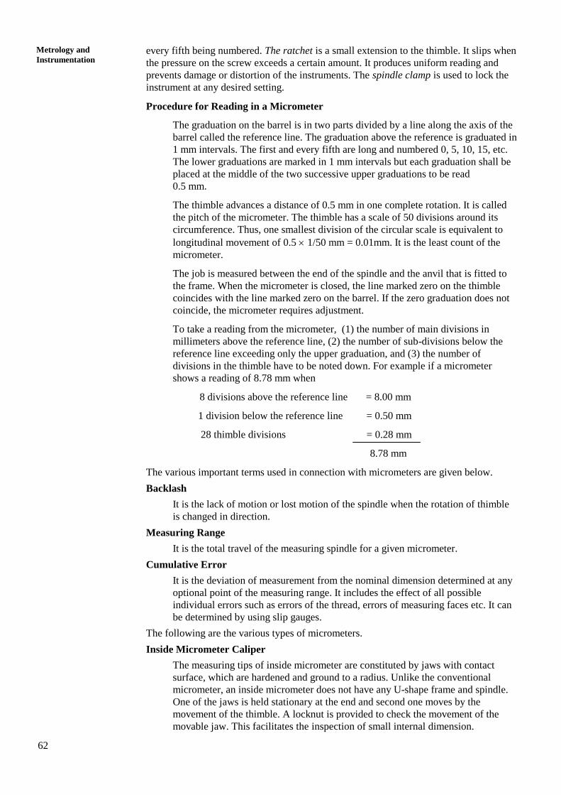
Figure 5.12 : Inside Micrometer Caliper
Inside Micrometer
The inside micrometer is intended for internal measurement to an accuracy of
0.001 mm. In principle, it is similar to an external micrometer and is used for
measuring holes with a diameter over 50 cm. It consists of :
(a) measuring unit
(b) extension rod with or without spacing collar, and
(c) handle.
When the micrometer screw is turned in the barrel, the distance between the
measuring faces of the micrometer can vary from 50 to 63 mm. To measure the
holes with a diameter over 63 mm, the micrometer is fitted with extension rods.
The extension rods of the sizes 13, 25, 50, 100, 150, 200 and 600 mm are in
common use.
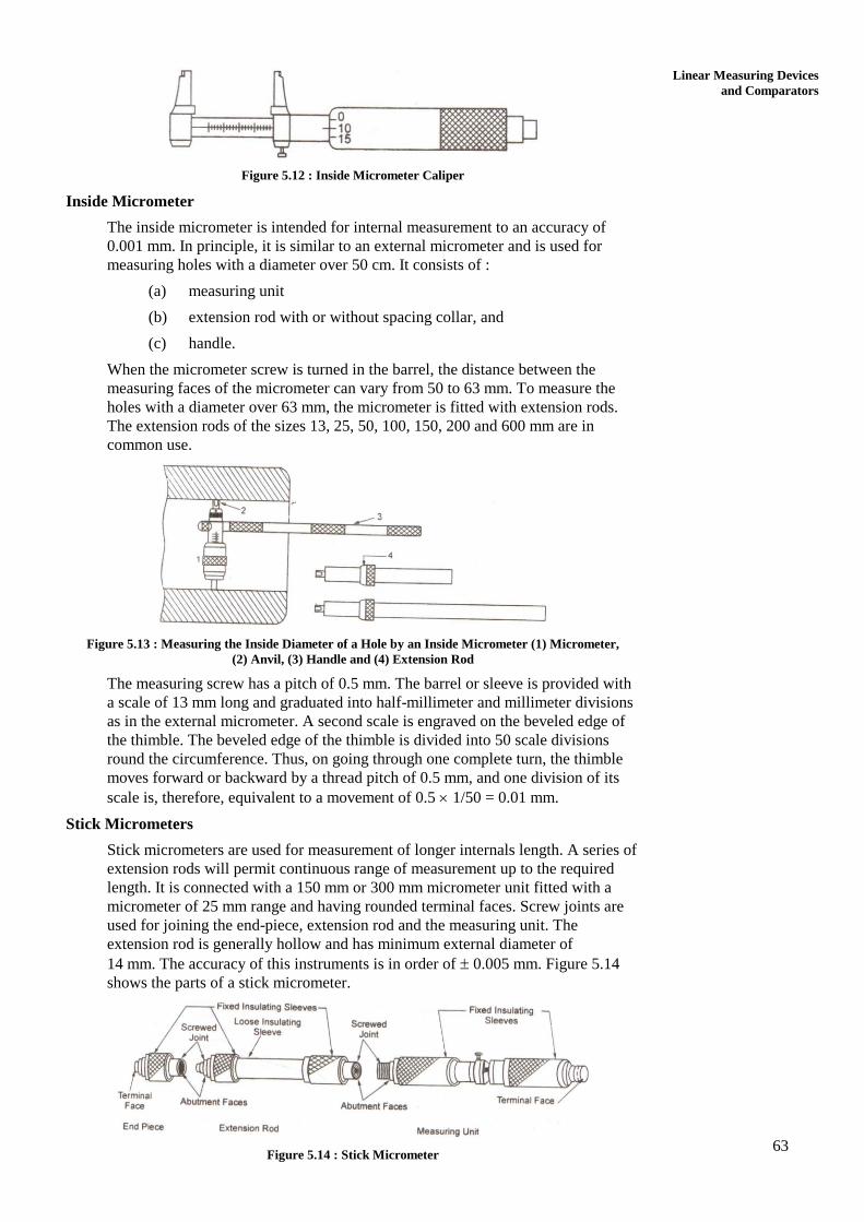
Figure 5.13 : Measuring the Inside Diameter of a Hole by an Inside Micrometer (1) Micrometer,
(2) Anvil, (3) Handle and (4) Extension Rod
The measuring screw has a pitch of 0.5 mm. The barrel or sleeve is provided with
a scale of 13 mm long and graduated into half-millimeter and millimeter divisions
as in the external micrometer. A second scale is engraved on the beveled edge of
the thimble. The beveled edge of the thimble is divided into 50 scale divisions
round the circumference. Thus, on going through one complete turn, the thimble
moves forward or backward by a thread pitch of 0.5 mm, and one division of its
scale is, therefore, equivalent to a movement of 0.5 1/50 = 0.01 mm.
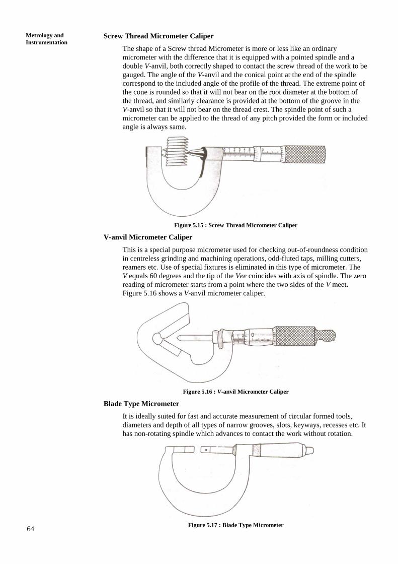
Stick Micrometers
Stick micrometers are used for measurement of longer internals length. A series of
extension rods will permit continuous range of measurement up to the required
length. It is connected with a 150 mm or 300 mm micrometer unit fitted with a
micrometer of 25 mm range and having rounded terminal faces. Screw joints are
used for joining the end-piece, extension rod and the measuring unit. The
extension rod is generally hollow and has minimum external diameter of
14 mm. The accuracy of this instruments is in order of 0.005 mm. Figure 5.14
shows the parts of a stick micrometer.
Figure 5.14 : Stick Micrometer
64
Metrology and
Instrumentation Screw Thread Micrometer Caliper
The shape of a Screw thread Micrometer is more or less like an ordinary
micrometer with the difference that it is equipped with a pointed spindle and a
double V-anvil, both correctly shaped to contact the screw thread of the work to be
gauged. The angle of the V-anvil and the conical point at the end of the spindle
correspond to the included angle of the profile of the thread. The extreme point of
the cone is rounded so that it will not bear on the root diameter at the bottom of
the thread, and similarly clearance is provided at the bottom of the groove in the
V-anvil so that it will not bear on the thread crest. The spindle point of such a
micrometer can be applied to the thread of any pitch provided the form or included
angle is always same.
Figure 5.15 : Screw Thread Micrometer Caliper
V-anvil Micrometer Caliper
This is a special purpose micrometer used for checking out-of-roundness condition
in centreless grinding and machining operations, odd-fluted taps, milling cutters,
reamers etc. Use of special fixtures is eliminated in this type of micrometer. The
V equals 60 degrees and the tip of the Vee coincides with axis of spindle. The zero
reading of micrometer starts from a point where the two sides of the V meet.
Figure 5.16 shows a V-anvil micrometer caliper.
Figure 5.16 : V-anvil Micrometer Caliper
Blade Type Micrometer
It is ideally suited for fast and accurate measurement of circular formed tools,
diameters and depth of all types of narrow grooves, slots, keyways, recesses etc. It
has non-rotating spindle which advances to contact the work without rotation.
Figure 5.17 : Blade Type Micrometer
65
Linear Measuring Devices
and Comparators Bench Micrometer
A bench micrometer is a high precision micrometer with an anvil retractor device
for repeated measurement. The worktable is adjustable and the indicator can
measure up to 1 m. The Anvil pressure is adjustable and linear friction transfer
mechanism is used between anvil and indicator for high accuracy.
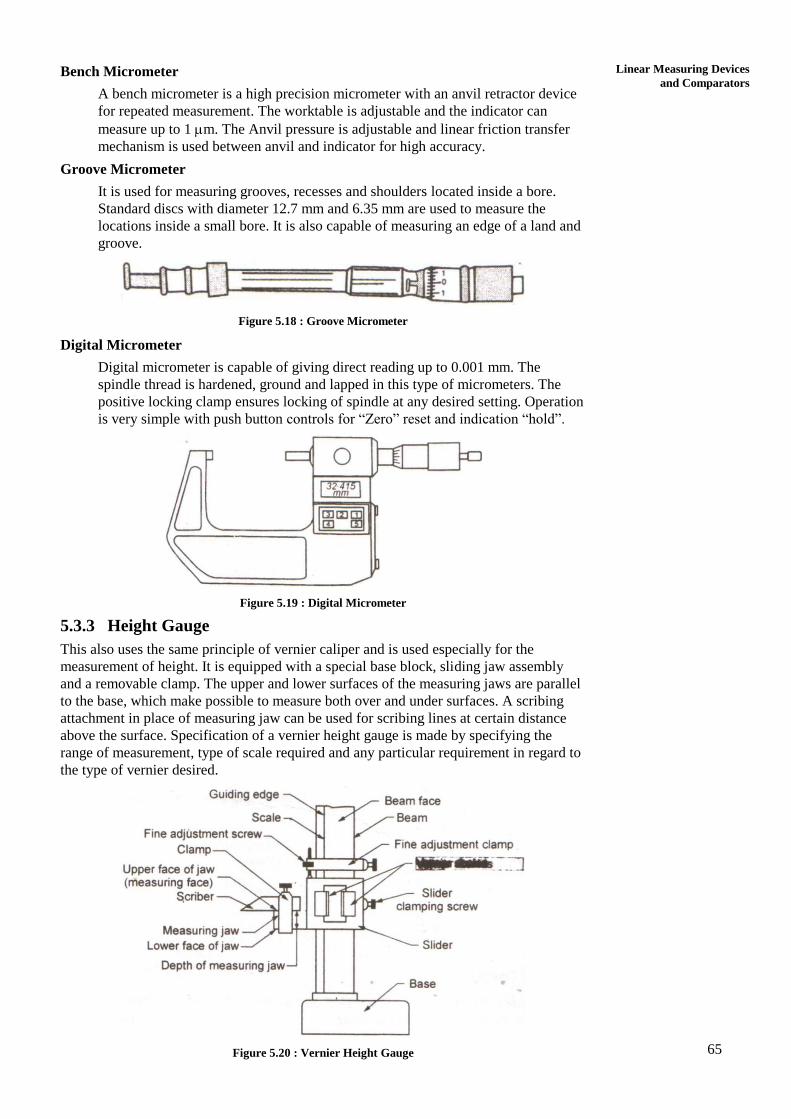
Groove Micrometer
It is used for measuring grooves, recesses and shoulders located inside a bore.
Standard discs with diameter 12.7 mm and 6.35 mm are used to measure the
locations inside a small bore. It is also capable of measuring an edge of a land and
groove.
Figure 5.18 : Groove Micrometer
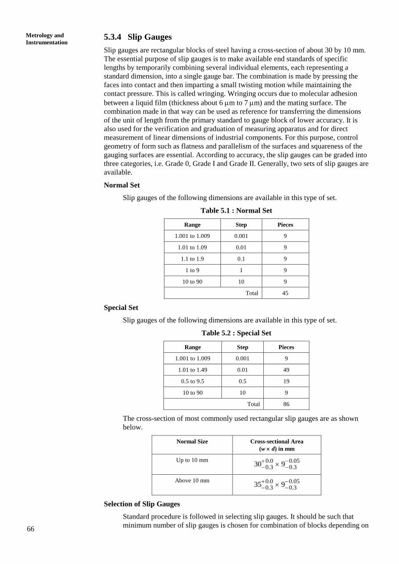
Digital Micrometer
Digital micrometer is capable of giving direct reading up to 0.001 mm. The
spindle thread is hardened, ground and lapped in this type of micrometers. The
positive locking clamp ensures locking of spindle at any desired setting. Operation
is very simple with push button controls for “Zero” reset and indication “hold”.
Figure 5.19 : Digital Micrometer
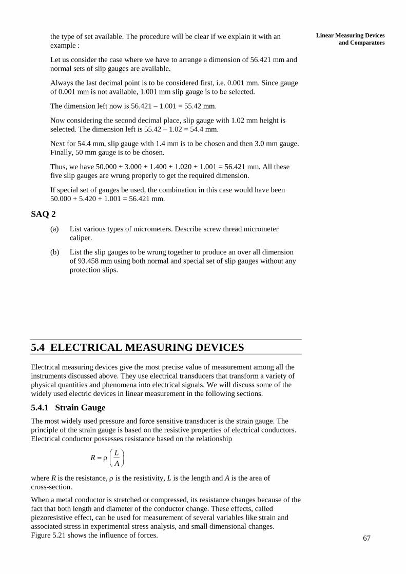
5.3.3 Height Gauge
This also uses the same principle of vernier caliper and is used especially for the
measurement of height. It is equipped with a special base block, sliding jaw assembly
and a removable clamp. The upper and lower surfaces of the measuring jaws are parallel
to the base, which make possible to measure both over and under surfaces. A scribing
attachment in place of measuring jaw can be used for scribing lines at certain distance
above the surface. Specification of a vernier height gauge is made by specifying the
range of measurement, type of scale required and any particular requirement in regard to
the type of vernier desired.
Figure 5.20 : Vernier Height Gauge
66
Metrology and
Instrumentation 5.3.4 Slip Gauges
Slip gauges are rectangular blocks of steel having a cross-section of about 30 by 10 mm.
The essential purpose of slip gauges is to make available end standards of specific
lengths by temporarily combining several individual elements, each representing a
standard dimension, into a single gauge bar. The combination is made by pressing the
faces into contact and then imparting a small twisting motion while maintaining the
contact pressure. This is called wringing. Wringing occurs due to molecular adhesion
between a liquid film (thickness about 6 m to 7 m) and the mating surface. The
combination made in that way can be used as reference for transferring the dimensions
of the unit of length from the primary standard to gauge block of lower accuracy. It is
also used for the verification and graduation of measuring apparatus and for direct
measurement of linear dimensions of industrial components. For this purpose, control
geometry of form such as flatness and parallelism of the surfaces and squareness of the
gauging surfaces are essential. According to accuracy, the slip gauges can be graded into
three categories, i.e. Grade 0, Grade I and Grade II. Generally, two sets of slip gauges are
available.
Normal Set
Slip gauges of the following dimensions are available in this type of set.
Table 5.1 : Normal Set
Range Step Pieces
1.001 to 1.009 0.001 9
1.01 to 1.09 0.01 9
1.1 to 1.9 0.1 9
1 to 9 1 9
10 to 90 10 9
Total 45
Special Set
Slip gauges of the following dimensions are available in this type of set.
Table 5.2 : Special Set
Range Step Pieces
1.001 to 1.009 0.001 9
1.01 to 1.49 0.01 49
0.5 to 9.5 0.5 19
10 to 90 10 9
Total 86
The cross-section of most commonly used rectangular slip gauges are as shown
below.
Normal Size Cross-sectional Area
(w d) in mm
Up to 10 mm 0.0 0.050.3 0.330 9
Above 10 mm 0.0 0.050.3 0.335 9
Selection of Slip Gauges
Standard procedure is followed in selecting slip gauges. It should be such that
minimum number of slip gauges is chosen for combination of blocks depending on
67
Linear Measuring Devices
and Comparators the type of set available. The procedure will be clear if we explain it with an
example :
Let us consider the case where we have to arrange a dimension of 56.421 mm and
normal sets of slip gauges are available.
Always the last decimal point is to be considered first, i.e. 0.001 mm. Since gauge
of 0.001 mm is not available, 1.001 mm slip gauge is to be selected.
The dimension left now is 56.421 – 1.001 = 55.42 mm.
Now considering the second decimal place, slip gauge with 1.02 mm height is
selected. The dimension left is 55.42 – 1.02 = 54.4 mm.
Next for 54.4 mm, slip gauge with 1.4 mm is to be chosen and then 3.0 mm gauge.
Finally, 50 mm gauge is to be chosen.
Thus, we have 50.000 + 3.000 + 1.400 + 1.020 + 1.001 = 56.421 mm. All these
five slip gauges are wrung properly to get the required dimension.
If special set of gauges be used, the combination in this case would have been
50.000 + 5.420 + 1.001 = 56.421 mm.
SAQ 2
(a) List various types of micrometers. Describe screw thread micrometer
caliper.
(b) List the slip gauges to be wrung together to produce an over all dimension
of 93.458 mm using both normal and special set of slip gauges without any
protection slips.
5.4 ELECTRICAL MEASURING DEVICES
Electrical measuring devices give the most precise value of measurement among all the
instruments discussed above. They use electrical transducers that transform a variety of
physical quantities and phenomena into electrical signals. We will discuss some of the
widely used electric devices in linear measurement in the following sections.
5.4.1 Strain Gauge
The most widely used pressure and force sensitive transducer is the strain gauge. The
principle of the strain gauge is based on the resistive properties of electrical conductors.
Electrical conductor possesses resistance based on the relationship
LR
A
where R is the resistance, is the resistivity, L is the length and A is the area of
cross-section.
When a metal conductor is stretched or compressed, its resistance changes because of the
fact that both length and diameter of the conductor change. These effects, called
piezoresistive effect, can be used for measurement of several variables like strain and
associated stress in experimental stress analysis, and small dimensional changes.
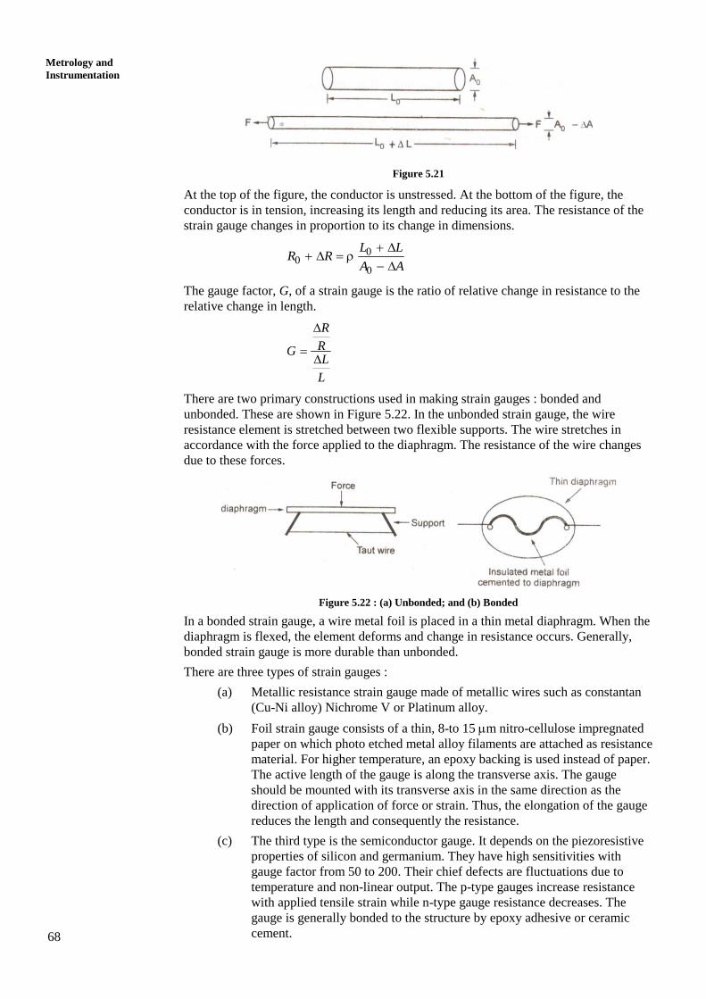
Figure 5.21 shows the influence of forces.
68
Metrology and
Instrumentation
Figure 5.21
At the top of the figure, the conductor is unstressed. At the bottom of the figure, the
conductor is in tension, increasing its length and reducing its area. The resistance of the
strain gauge changes in proportion to its change in dimensions.
00
0
L LR R
A A
The gauge factor, G, of a strain gauge is the ratio of relative change in resistance to the
relative change in length.
R
RGL
L
There are two primary constructions used in making strain gauges : bonded and
unbonded. These are shown in Figure 5.22. In the unbonded strain gauge, the wire
resistance element is stretched between two flexible supports. The wire stretches in
accordance with the force applied to the diaphragm. The resistance of the wire changes
due to these forces.
Figure 5.22 : (a) Unbonded; and (b) Bonded
In a bonded strain gauge, a wire metal foil is placed in a thin metal diaphragm. When the
diaphragm is flexed, the element deforms and change in resistance occurs. Generally,
bonded strain gauge is more durable than unbonded.
There are three types of strain gauges :
(a) Metallic resistance strain gauge made of metallic wires such as constantan
(Cu-Ni alloy) Nichrome V or Platinum alloy.
(b) Foil strain gauge consists of a thin, 8-to 15 m nitro-cellulose impregnated
paper on which photo etched metal alloy filaments are attached as resistance
material. For higher temperature, an epoxy backing is used instead of paper.
The active length of the gauge is along the transverse axis. The gauge
should be mounted with its transverse axis in the same direction as the
direction of application of force or strain. Thus, the elongation of the gauge
reduces the length and consequently the resistance.
(c) The third type is the semiconductor gauge. It depends on the piezoresistive
properties of silicon and germanium. They have high sensitivities with
gauge factor from 50 to 200. Their chief defects are fluctuations due to
temperature and non-linear output. The p-type gauges increase resistance
with applied tensile strain while n-type gauge resistance decreases. The
gauge is generally bonded to the structure by epoxy adhesive or ceramic
cement.
69
Linear Measuring Devices
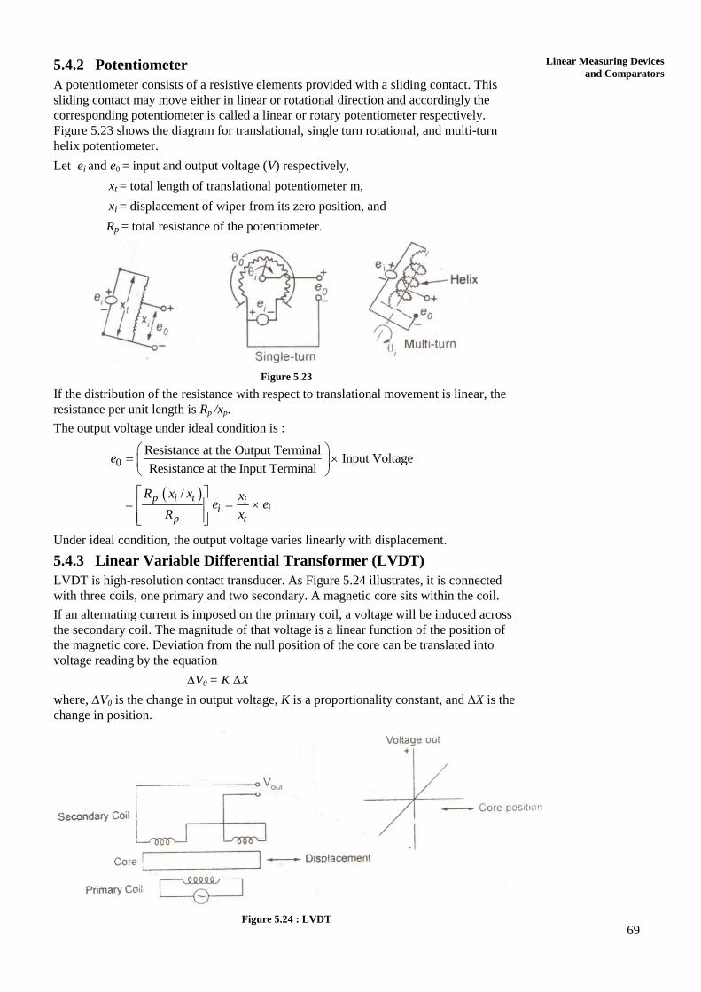
and Comparators 5.4.2 Potentiometer
A potentiometer consists of a resistive elements provided with a sliding contact. This
sliding contact may move either in linear or rotational direction and accordingly the
corresponding potentiometer is called a linear or rotary potentiometer respectively.
Figure 5.23 shows the diagram for translational, single turn rotational, and multi-turn
helix potentiometer.
Let ei and e0 = input and output voltage (V) respectively,
xt = total length of translational potentiometer m,
xi = displacement of wiper from its zero position, and
Rp = total resistance of the potentiometer.
Figure 5.23
If the distribution of the resistance with respect to translational movement is linear, the
resistance per unit length is Rp /xp.
The output voltage under ideal condition is :
0Resistance at the Output Terminal
Input VoltageResistance at the Input Terminal
e
/p i t i
i ip t
R x x xe e
R x
Under ideal condition, the output voltage varies linearly with displacement.
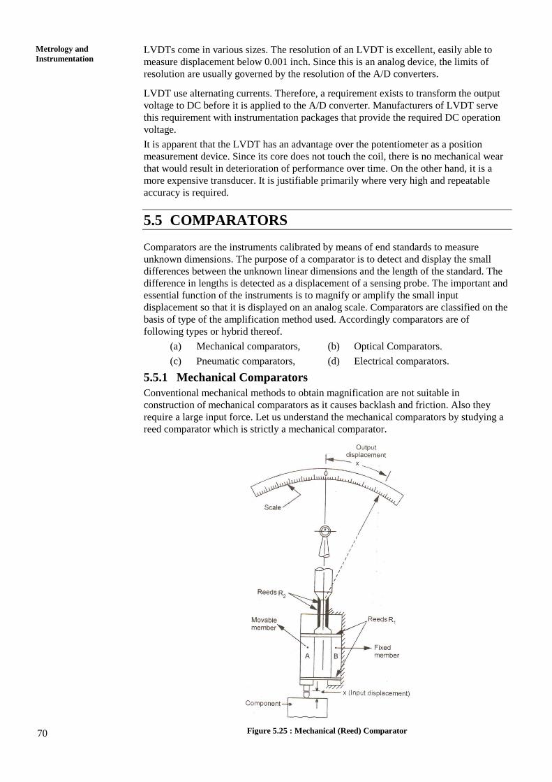
5.4.3 Linear Variable Differential Transformer (LVDT)
LVDT is high-resolution contact transducer. As Figure 5.24 illustrates, it is connected
with three coils, one primary and two secondary. A magnetic core sits within the coil.
If an alternating current is imposed on the primary coil, a voltage will be induced across
the secondary coil. The magnitude of that voltage is a linear function of the position of
the magnetic core. Deviation from the null position of the core can be translated into
voltage reading by the equation
V0 = K X
where, V0 is the change in output voltage, K is a proportionality constant, and X is the
change in position.
Figure 5.24 : LVDT
70
Metrology and
Instrumentation LVDTs come in various sizes. The resolution of an LVDT is excellent, easily able to
measure displacement below 0.001 inch. Since this is an analog device, the limits of
resolution are usually governed by the resolution of the A/D converters.
LVDT use alternating currents. Therefore, a requirement exists to transform the output
voltage to DC before it is applied to the A/D converter. Manufacturers of LVDT serve
this requirement with instrumentation packages that provide the required DC operation
voltage.
It is apparent that the LVDT has an advantage over the potentiometer as a position
measurement device. Since its core does not touch the coil, there is no mechanical wear
that would result in deterioration of performance over time. On the other hand, it is a
more expensive transducer. It is justifiable primarily where very high and repeatable
accuracy is required.
5.5 COMPARATORS
Comparators are the instruments calibrated by means of end standards to measure
unknown dimensions. The purpose of a comparator is to detect and display the small
differences between the unknown linear dimensions and the length of the standard. The
difference in lengths is detected as a displacement of a sensing probe. The important and
essential function of the instruments is to magnify or amplify the small input
displacement so that it is displayed on an analog scale. Comparators are classified on the
basis of type of the amplification method used. Accordingly comparators are of
following types or hybrid thereof.
(a) Mechanical comparators, (b) Optical Comparators.
(c) Pneumatic comparators, (d) Electrical comparators.
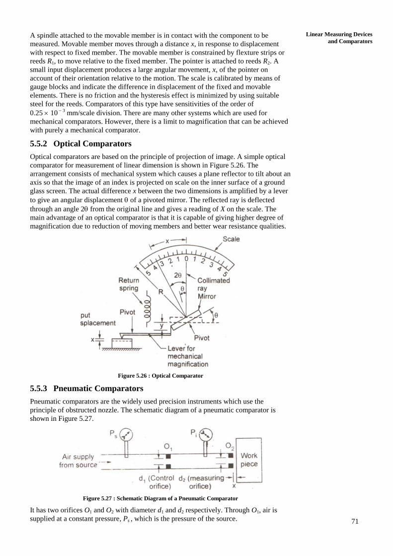
5.5.1 Mechanical Comparators
Conventional mechanical methods to obtain magnification are not suitable in
construction of mechanical comparators as it causes backlash and friction. Also they
require a large input force. Let us understand the mechanical comparators by studying a
reed comparator which is strictly a mechanical comparator.
Figure 5.25 : Mechanical (Reed) Comparator
71
Linear Measuring Devices
and Comparators A spindle attached to the movable member is in contact with the component to be
measured. Movable member moves through a distance x, in response to displacement
with respect to fixed member. The movable member is constrained by flexture strips or
reeds R1, to move relative to the fixed member. The pointer is attached to reeds R2. A
small input displacement produces a large angular movement, x, of the pointer on
account of their orientation relative to the motion. The scale is calibrated by means of
gauge blocks and indicate the difference in displacement of the fixed and movable
elements. There is no friction and the hysteresis effect is minimized by using suitable
steel for the reeds. Comparators of this type have sensitivities of the order of
0.25 10 3
mm/scale division. There are many other systems which are used for
mechanical comparators. However, there is a limit to magnification that can be achieved
with purely a mechanical comparator.
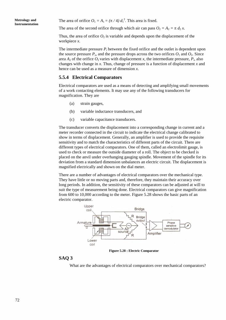
5.5.2 Optical Comparators
Optical comparators are based on the principle of projection of image. A simple optical
comparator for measurement of linear dimension is shown in Figure 5.26. The
arrangement consists of mechanical system which causes a plane reflector to tilt about an
axis so that the image of an index is projected on scale on the inner surface of a ground
glass screen. The actual difference x between the two dimensions is amplified by a lever
to give an angular displacement of a pivoted mirror. The reflected ray is deflected
through an angle 2 from the original line and gives a reading of X on the scale. The
main advantage of an optical comparator is that it is capable of giving higher degree of
magnification due to reduction of moving members and better wear resistance qualities.
Figure 5.26 : Optical Comparator
5.5.3 Pneumatic Comparators
Pneumatic comparators are the widely used precision instruments which use the
principle of obstructed nozzle. The schematic diagram of a pneumatic comparator is
shown in Figure 5.27.
Figure 5.27 : Schematic Diagram of a Pneumatic Comparator
It has two orifices O1 and O2 with diameter d1 and d2 respectively. Through O1, air is
supplied at a constant pressure, Ps , which is the pressure of the source.
72
Metrology and
Instrumentation The area of orifice O1 = A1 = ( / 4) d1
2. This area is fixed.
The area of the second orifice through which air can pass O2 = A2 = d2 x.
Thus, the area of orifice O2 is variable and depends upon the displacement of the
workpiece x.
The intermediate pressure Pi between the fixed orifice and the outlet is dependent upon
the source pressure Ps, and the pressure drops across the two orifices O1 and O2. Since
area A2 of the orifice O2 varies with displacement x, the intermediate pressure, Pi, also
changes with change in x. Thus, change of pressure is a function of displacement x and
hence can be used as a measure of dimension x.
5.5.4 Electrical Comparators
Electrical comparators are used as a means of detecting and amplifying small movements
of a work contacting elements. It may use any of the following transducers for
magnification. They are
(a) strain gauges,
(b) variable inductance transducers, and
(c) variable capacitance transducers.
The transducer converts the displacement into a corresponding change in current and a
meter recorder connected in the circuit to indicate the electrical change calibrated to
show in terms of displacement. Generally, an amplifier is used to provide the requisite
sensitivity and to match the characteristics of different parts of the circuit. There are
different types of electrical comparators. One of them, called an electrolimit gauge, is
used to check or measure the outside diameter of a roll. The object to be checked is
placed on the anvil under overhanging gauging spindle. Movement of the spindle for its
deviation from a standard dimension unbalances an electric circuit. The displacement is
magnified electrically and shown on the dial meter.
There are a number of advantages of electrical comparators over the mechanical type.
They have little or no moving parts and, therefore, they maintain their accuracy over
long periods. In addition, the sensitivity of these comparators can be adjusted at will to
suit the type of measurement being done. Electrical comparators can give magnification
from 600 to 10,000 according to the meter. Figure 5.28 shows the basic parts of an
electric comparator.
Figure 5.28 : Electric Comparator
SAQ 3
What are the advantages of electrical comparators over mechanical comparators?
73
Linear Measuring Devices
and Comparators 5.6 SUMMARY
In this unit, linear measuring devices and comparators have been discussed. The unit
begins with the description of non-precision measuring devices like scale (ruler), caliper,
divider and telescopic gauge. Next, precision measuring devices, viz. vernier caliper,
micrometer, height gauges and slip gauges are explained. The principles of electrical
measuring devices like strain gauges, LVDTs, potentiometers have also been discussed.
The four basic types of comparator viz. mechanical, optical, pneumatic and electrical are
discussed.
5.7 KEY WORDS
Vernier Constant : It is defined as the difference between one small
division of the vernier scale and one small
division of the main scale.
Least Count : It is the minimum distance that can be measured
by a vernier caliper or a micrometer accurately.
Wringing : It is the process of combining two slip gauges by
application of pressure normal to the surface to be
joined with sliding motion of one surface over the
other.
Transducer : A transducer is a device which, when actuated,
transform energy from one form to another.
Piezo-resistive Effect : It is defined as the phenomenon due to which
resistivity of a conductor changes when it is
subjected to strain.
Gauge Factor : The gauge factor of a strain gauge is the ratio of
relative change in resistance to the relative change
in length.
5.8 ANSWERS TO SAQs
SAQ 1
See preceding text for answer.
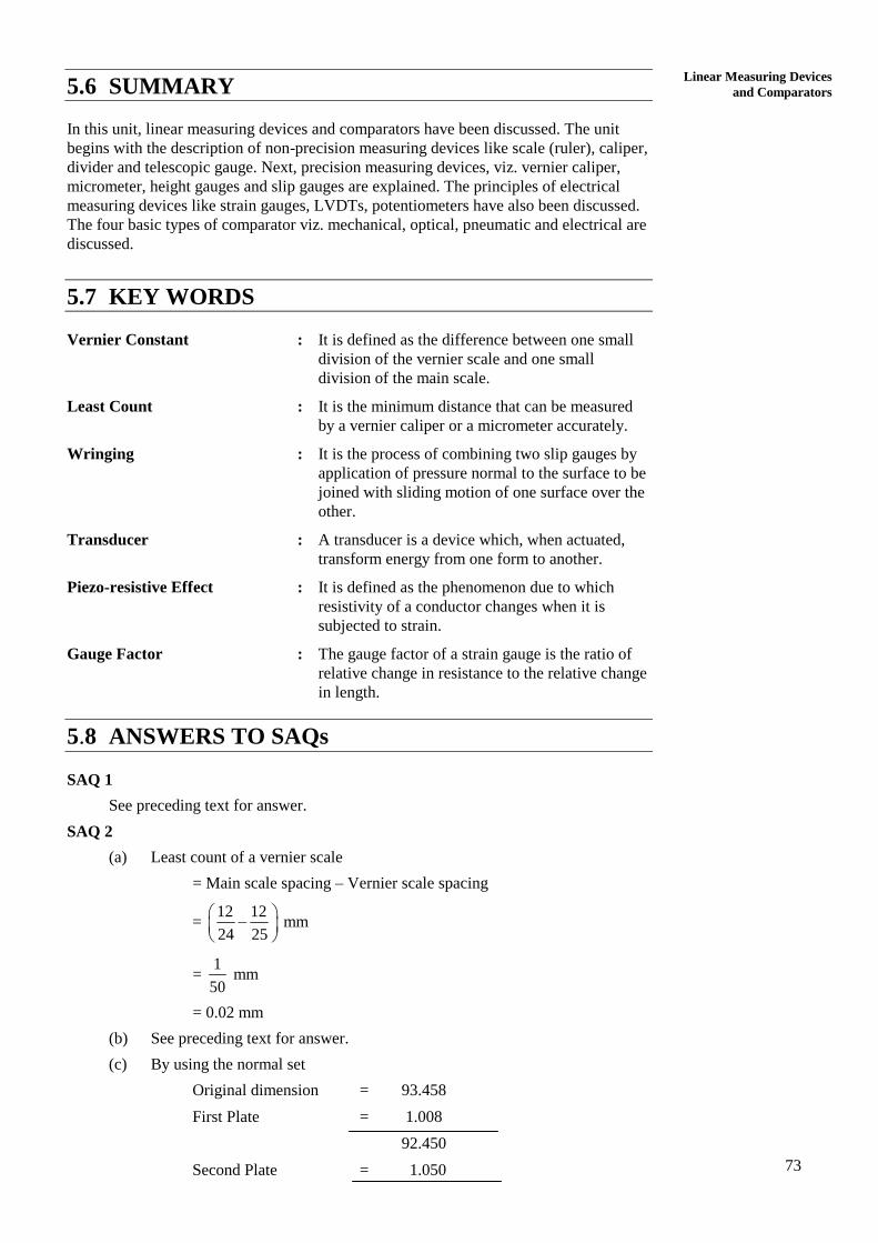
SAQ 2
(a) Least count of a vernier scale
= Main scale spacing – Vernier scale spacing
= 12 12
24 25
mm
= 1
50 mm
= 0.02 mm
(b) See preceding text for answer.
(c) By using the normal set
Original dimension = 93.458
First Plate = 1.008
92.450
Second Plate = 1.050
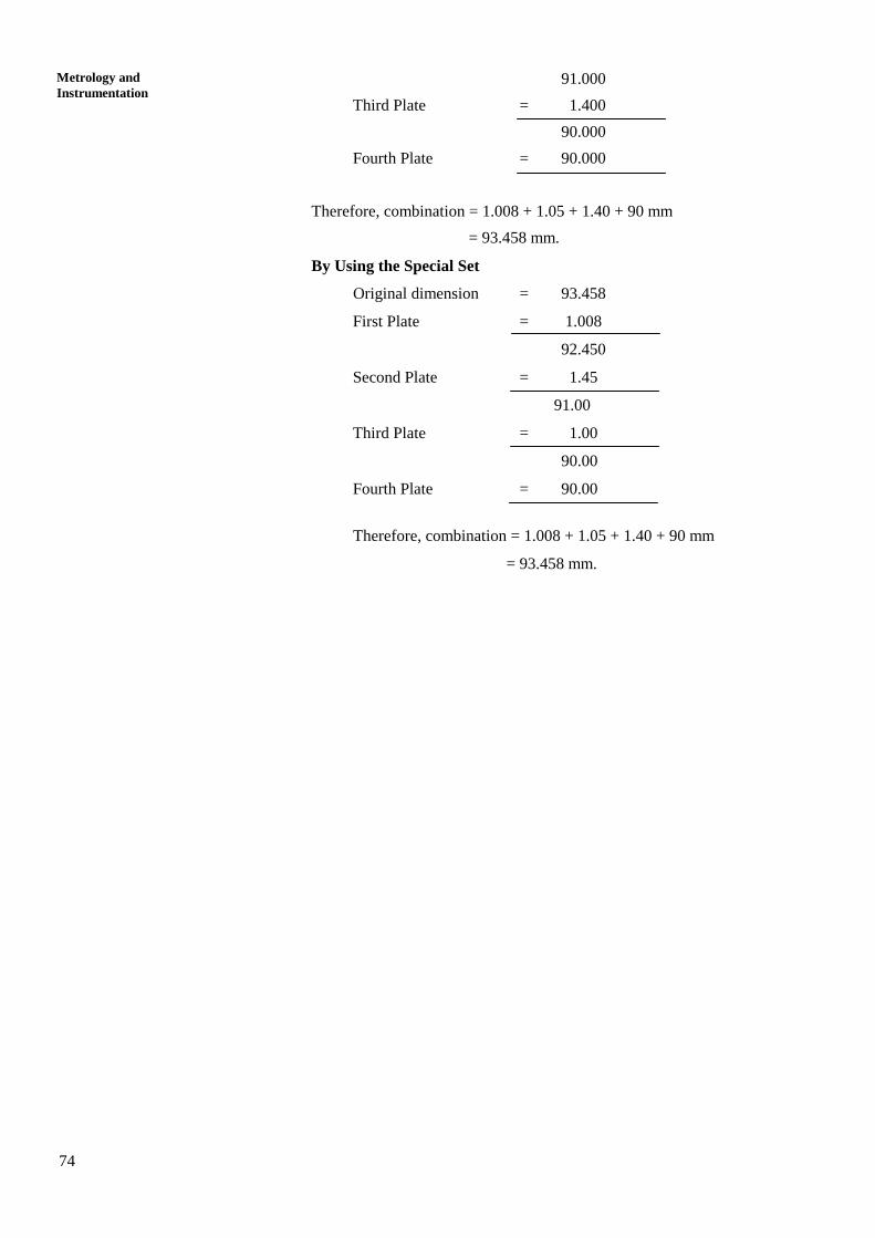
74
Metrology and
Instrumentation 91.000
Third Plate = 1.400
90.000
Fourth Plate = 90.000
Therefore, combination = 1.008 + 1.05 + 1.40 + 90 mm
= 93.458 mm.
By Using the Special Set
Original dimension = 93.458
First Plate = 1.008
92.450
Second Plate = 1.45
91.00
Third Plate = 1.00
90.00
Fourth Plate = 90.00
Therefore, combination = 1.008 + 1.05 + 1.40 + 90 mm
= 93.458 mm.