UNIT 45: Riser Design Wizard - Finite Solutionsoutgoing.finitesolutions.com/SOLIDCastWorkbook/Unit...
32
EFFECTIVE CASTING SIMULATION 45-1 UNIT 45: Riser Design Wizard The Riser Design Wizard allows you to analyze a casting model without risers or feeders, and determine the number, placement and size of risers or feeders that should be attached to the casting. After performing these calculations, you should add the risers to the model and perform a verification simulation to determine whether any adjustments in design may be necessary. This wizard is designed primarily for shrinking alloys, such as steel, aluminum, copper and white cast irons. Gray and ductile irons, which typically have an expansion phase, have their own riser design functions built into the Iron Property Calculator utilities which are a part of SOLIDCast. BASIC CONCEPTS The Riser Design Wizard uses the concept of a “modulus” to analyze the casting, differentiate feeding areas, and design appropriately-sized risers. The casting modulus is a term coined years ago to describe the ratio of the volume to surface area of a casting, or of its various sections. According to Chvorinov’s rule, the sections of a casting which have a higher modulus (volume:surface area ratio) will freeze last, while those sections with a lower modulus value will freeze earlier. The ideal situation is for the casting to undergo directional solidification toward the riser (or feeder); this generally means that a riser needs to be attached to a section of the casting that has the highest modulus value. The modulus of the riser should be equal to or greater than that of the casting to which it is attached. This, in theory, will allow any contraction that is taking place as the casting solidifies to be fed by a pool of molten liquid metal in the riser, and thus prevent shrinkage from occurring, as illustrated in the following figure: Since modulus is defined as volume / surface area, the units generally used units of length as follows:
Transcript of UNIT 45: Riser Design Wizard - Finite Solutionsoutgoing.finitesolutions.com/SOLIDCastWorkbook/Unit...

EFFECTIVE CASTING SIMULATION
45-1
UNIT 45: Riser Design Wizard The Riser Design Wizard allows you to analyze a casting model without risers or feeders, and determine the number, placement and size of risers or feeders that should be attached to the casting. After performing these calculations, you should add the risers to the model and perform a verification simulation to determine whether any adjustments in design may be necessary. This wizard is designed primarily for shrinking alloys, such as steel, aluminum, copper and white cast irons. Gray and ductile irons, which typically have an expansion phase, have their own riser design functions built into the Iron Property Calculator utilities which are a part of SOLIDCast. BASIC CONCEPTS The Riser Design Wizard uses the concept of a “modulus” to analyze the casting, differentiate feeding areas, and design appropriately-sized risers. The casting modulus is a term coined years ago to describe the ratio of the volume to surface area of a casting, or of its various sections. According to Chvorinov’s rule, the sections of a casting which have a higher modulus (volume:surface area ratio) will freeze last, while those sections with a lower modulus value will freeze earlier. The ideal situation is for the casting to undergo directional solidification toward the riser (or feeder); this generally means that a riser needs to be attached to a section of the casting that has the highest modulus value. The modulus of the riser should be equal to or greater than that of the casting to which it is attached. This, in theory, will allow any contraction that is taking place as the casting solidifies to be fed by a pool of molten liquid metal in the riser, and thus prevent shrinkage from occurring, as illustrated in the following figure:
Since modulus is defined as volume / surface area, the units generally used units of length as follows:

EFFECTIVE CASTING SIMULATION
45-2
English Units: in.3 / in.2 = in Metric Units: cm3 / cm2 = cm The Riser Design Wizard calculates an “effective modulus”, or “thermal modulus”, from the results of a simulation of an unrigged casting. This approach gives a modulus value equivalent to the volume:surface area ratio for each point within a casting, depending on how the casting solidified. This is considerably more accurate than the traditional approach of estimating volumes and surface areas of a casting through manual calculations, as it takes into account the dynamics of the process, such as heat saturation, etc. Another consideration for proper riser design is how much liquid metal is required by the casting, and how much metal a riser of a given size can deliver. The amount required by the casting is a function of the volume of the feeding area and the contraction of the alloy. The amount of metal which can be delivered by a riser is a function of its Riser Efficiency; a riser which has an efficiency of 15%, for example, can deliver 15% of its total volume of metal to feed the contraction which is occurring in both the casting and the riser. An illustration of two common riser types and typical values which might be used for efficiency, measured as the amount of feed metal delivered, is as follows:
Riser efficiency has been estimated a number of different ways. Two of these are incorporated into the Riser Design Wizard:
1. AFS Method: AFS/CMI publishes a handbook entitled Basic Principles of Gating and Risering. This handbook contains Figure 8.2, “Surface Area to Volume Relationships for Various Riser Types”. This chart shows the appropriate ratio of Riser:Casting volume for various Riser:Casting modulus ratios and various types of risers. A Riser Efficiency Factor can be derived from this chart which gives the efficiency of a specific riser attached to a specific casting. This is the “default” efficiency which is used in the Riser Design Wizard.

EFFECTIVE CASTING SIMULATION
45-3
2. Wlodawer Method: A number of foundry engineers use an approach pioneered
by Wlodawer, who defined an efficiency according to the following equation: (Vc + Vr) s = Vr E Where Vc = volume of casting
Vr = volume of riser E= Efficiency of riser (%) s= shrinkage of alloy (%)
Rearranging terms in this equation, the required riser volume is Vr = Vc / (E/s - 1)
Most people using the Wlodawer approach assume a specific efficiency (E) for a specific type of riser. These assumed efficiencies are built into the Riser Design Wizard for unsleeved risers, insulating sleeves and exothermic sleeves. You can also enter a different riser efficiency factor, based on your experience with a particular type of riser.
It should be noted that the Riser Design Wizard uses the Critical Fraction Solid point on the alloy curves to determine the amount of shrinkage that the alloy undergoes. This value can be read on the alloy curve at the CFS point; note that it may be substantially lower than the value of the shrinkage entered in "System Parameters/Alloy Curves" at the beginning of the simulation. USING THE RISER DESIGN WIZARD To use the Riser Design Wizard, you should first run a simulation of a casting model with no risers or feeders attached. We call this ‘freezing naked’. You may optionally include gating in this model in order to take into account temperature distribution within the casting due to filling. You may also include such items as chills, if you plan to use these and want their effect to taken into account when designing the risers.

EFFECTIVE CASTING SIMULATION
45-4
As an example, consider the casting model shown on the previous page. Here we have a model of a casting only, with no risers, gating or chills. The first step is to mesh this casting model and run a simulation.
Hint: In order to make this step quicker, there are some things that we can do to make the simulation run faster than normal. First of all, since riser calculations are generally not as exacting as a full simulation, we can generally mesh the casting model with fewer (larger) nodes to create a coarser mesh which runs faster. Also, the Material Density (volumetric) calculations are not used when analyzing the results for riser design. Therefore, from the main SOLIDCast menu you can select Tools… System Parameters… Model & Sim and set the Volumetric Calculation Interval to a high number (for example, 1000). This will cause the volumetric calculations to be performed less frequently during the simulation, and will speed up the overall speed of the simulation. Be sure to reset this entry to a normal setting (the default value is 10) before running any other simulations, or your Material Density results will be unusable.
It is important to remember that you should place mold material around the casting model that is representative of the type of mold material that will be used to produce the casting. Normally, you should surround the casting completely with the mold material – this means that, if you are creating a mold during meshing, you should have the “Open Top” option turned OFF. Also, if you are creating a shell around the casting model as in investment casting, the shell thickness should be representative of the actual shell thickness, and you should run the View Factor Calculation on the meshed model prior to running the simulation. Also, be sure to allow the simulation of the casting to run until the casting is 100% solid. This is the default setting when starting a simulation. Once the simulation has completed, double-click the Simulation entry on the Project Tree (on the left side of the screen). This displays the Simulation Status window as shown in the example below; the status should say “Complete” as shown.
Close this window to proceed to the next step.

EFFECTIVE CASTING SIMULATION
45-5
At the SOLIDCast main menu, select Simulation. You will see an entry on the sub-menu which is titled Riser Design Wizard, as shown in the image below:
Select Riser Design Wizard from the menu. The following screen should appear:

EFFECTIVE CASTING SIMULATION
45-6
This is the initial introduction screen for the Riser Design Wizard. If you don’t want this screen to appear each time you start the Wizard, just click on the box labeled “Do not show this step next time.” Notice at the bottom of this window are a set of buttons labeled Cancel, Back, Next, and Finish. These are the buttons that you can use to navigate through the wizard to perform its functions. Now click on the button labeled Next. You will see the following:
This screen allows you to perform one of two functions:
1. Calculate and display modulus values throughout the casting. 2. Calculate and display separate feeding areas within the casting, and design a
riser for each of these areas.

EFFECTIVE CASTING SIMULATION
45-7
CALCULATE AND DISPLAY CASTING MODULUS This feature allows you to view modulus values throughout the casting. This can be useful as a way of visualizing which portions of the casting will freeze in which order, and identifying which sections of the casting are heaviest from a thermal standpoint. This information can also be of value for process information; for example, in some iron casting processes, the modulus value is part of determining how much expansion might occur, and whether a given casting is a good candidate for production as a riserless casting. To view modulus values, on the window click the button labeled Calculate and Display Casting Modulus. The window should change so that it appears as follows:
EFFECTIVE CASTING SIMULATION
45-8
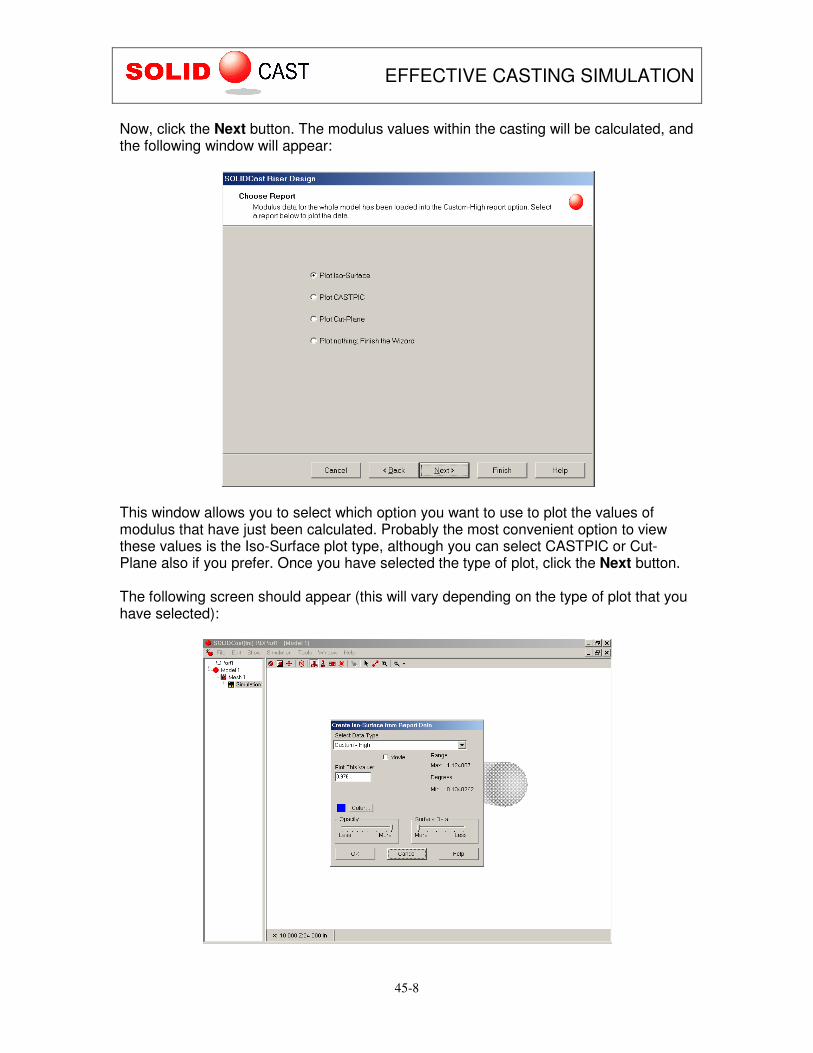
Now, click the Next button. The modulus values within the casting will be calculated, and the following window will appear:
This window allows you to select which option you want to use to plot the values of modulus that have just been calculated. Probably the most convenient option to view these values is the Iso-Surface plot type, although you can select CASTPIC or Cut-Plane also if you prefer. Once you have selected the type of plot, click the Next button. The following screen should appear (this will vary depending on the type of plot that you have selected):
EFFECTIVE CASTING SIMULATION
45-9
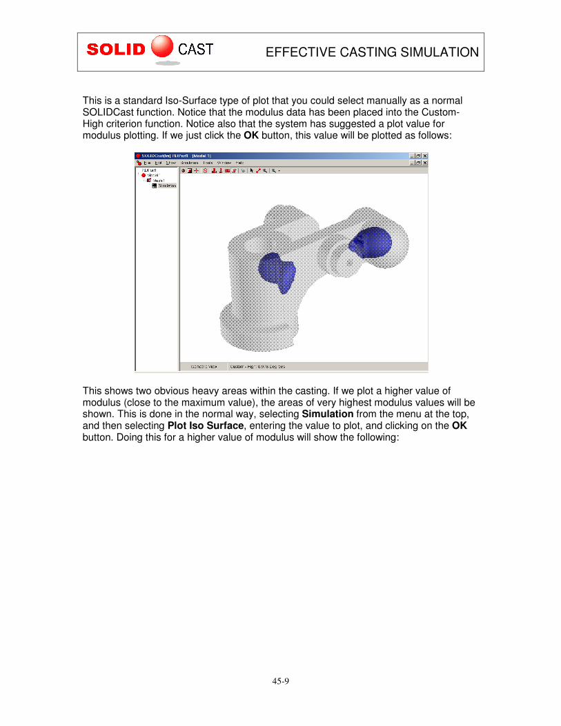
This is a standard Iso-Surface type of plot that you could select manually as a normal SOLIDCast function. Notice that the modulus data has been placed into the Custom-High criterion function. Notice also that the system has suggested a plot value for modulus plotting. If we just click the OK button, this value will be plotted as follows:
This shows two obvious heavy areas within the casting. If we plot a higher value of modulus (close to the maximum value), the areas of very highest modulus values will be shown. This is done in the normal way, selecting Simulation from the menu at the top, and then selecting Plot Iso Surface, entering the value to plot, and clicking on the OK button. Doing this for a higher value of modulus will show the following:

EFFECTIVE CASTING SIMULATION
45-10
This allows us to plot various values to examine what might be happening in this casting. Keep in mind that we are plotting modulus values, which indicate the heaviness of various sections within the casting and the order in which these sections will likely solidify. How do you get back to the Riser Design Wizard after plotting various values of modulus in SOLIDCast? Notice on the Windows Taskbar that there is a button labeled SOLIDCast Riser Design Wizard. This means that the wizard is still active while you are plotting.
To get back to the wizard, simply click on the button on the SOLIDCast Riser Design Wizard Taskbar as shown. This will restore the wizard on the screen, and it will appear as follows:

EFFECTIVE CASTING SIMULATION
45-11
Now, to perform other tasks with the Riser Design Wizard, we can just click the Back button until we get to the desired screen. If you wanted to exit the Riser Design Wizard at this point, you could click the Finish or Cancel buttons.

EFFECTIVE CASTING SIMULATION
45-12
DESIGNING RISERS As mentioned in the previous section, the first screen that you see after the initial Introduction screen for the Riser Design Wizard is the following:
The previous section showed us how to calculate and display the casting modulus. Now we will learn to use the Riser Design Wizard to actually design risers for a casting. This is done by selecting the option titled Design Risers as shown above. When the Design Risers option is selected, the Riser Design Wizard will first perform a calculation of modulus values. It then uses pattern-recognition software to identify separate feeding areas within the casting (consisting of isolated areas of higher modulus values), each of which may require a separate riser.

EFFECTIVE CASTING SIMULATION
45-13
You will notice that on the Design Risers screen there is a slider bar labeled SENSITIVITY. This bar determines how sensitive the pattern-recognition software is in identifying isolated areas requiring feeding. There is also a check box which is labeled Single Riser. These selections will determine how many risers are identified as being required for a casting, as follows:
• When the slider bar is moved to the left, this indicates LOW SENSITIVITY. At this setting, only larger isolated areas will be identified as being separate feed areas requiring a riser. Very small isolated areas will be ignored. This setting would typically be used for Heavy Section Castings.
• When the slider bar is moved to the right, this indicates HIGH SENSITIVITY. At this setting, even very small isolated areas will be identified as being separate feed areas requiring a riser. This setting would typically be used for Light Section Castings.
• When Single Riser is selected, the system will consider only one riser for the entire casting, regardless of how many separate feed areas occur within the casting. This selection should be used with some caution.
It may take some experimentation with castings of various types to determine the appropriate settings for the castings that you are producing. One approach is to try analyzing a casting at both the LOW SENSITIVITY and HIGH SENSITIVITY settings to determine if there is a difference. With some castings, the results will be the same (same number of risers), with other castings the results will be different. The figure below shows some examples of castings that might be classified as heavy section, intermediate, and light section:
It must be emphasized that, in all cases, after designing risers with the Riser Design Wizard, a simulation of the casting and risers should be run with SOLIDCast in order to verify the design.

EFFECTIVE CASTING SIMULATION
45-14
Designing risers in this way is only an approximation in order to get a starting point for the final design; only by running a full simulation can you verify whether this design is appropriate or whether further modifications to the casting design or riser design are necessary. Once you have selected the settings for analysis of your casting, click the Next button on the Riser Design screen. You will see a wizard screen similar to the following:
This screen indicates that, at the settings that were used on the previous screen, the Riser Design Wizard has determined that there are 2 separate, isolated feeding areas within the casting requiring risers. This number, of course, will vary from one casting to another, and also with the settings used on the previous screen. Note that on this screen, there is a message which says Modulus value of 1.007 was used to identify feed areas. This means that the pattern recognition software determined that the isolated feeding areas could be seen most clearly by plotting a modulus value of 1.007. This indicates that you could visualize these isolated areas by having the system calculate the modulus and then plot a value of 1.007 (see the previous section on CALCULATING AND DISPLAYING MODULUS VALUES).

EFFECTIVE CASTING SIMULATION
45-15
At this point, we have two options:
1. We can view the model to determine where these feeding areas are located. 2. We can calculate the appropriate riser size based on modulus and volume
requirements. We will examine the second option (riser size calculation) first, as this is the option which is selected by default. CALCULATING RISER SIZE To calculate the size for a riser, select one of the risers shown above and highlight it (this is done with a single click of the mouse on Riser 1, Riser 2, or whichever). You should see a screen appear as follows:
This is the SOLIDCast Riser Calculator. There are a variety of displayed values and calculation buttons. The meaning of each of these is as shown on the following pages.
EFFECTIVE CASTING SIMULATION
45-16
Casting Modulus This is the maximum modulus of the casting within the feeding area which this riser is intended to feed. It is NOT necessarily the maximum modulus within the casting. Normally, you would want the riser to have a modulus value equal to or greater than this Casting Modulus, for proper directional solidification. Casting Volume This is the volume of the casting within the feeding area which this riser is intended to feed. This will be an important consideration in the design of this riser. The riser must be able to provide enough volume of feed metal to compensate for the contraction which will occur in this casting volume. Riser:Casting Modulus Ratio This indicates the ratio of the modulus of the riser to the modulus of the casting. A typical value would be 1.2. The wizard initially defaults to this value. You may enter a different value if you want. Remember, for proper functioning of the riser, its modulus should normally be equal to or greater than that of the portion of the casting to which it is attached. Required Riser Modulus This is a calculated field giving the modulus that you will require for this riser. Its formula is:
Casting Modulus X Riser:Casting Modulus Ratio Riser Modulus Increase Factor This is a factor which is to be applied to the riser modulus based on whether the riser is unsleeved, has an insulated sleeve, or an exothermic sleeve. The concept here is that a sleeve acts to insulate the riser and reduce heat transfer to the mold. The effect is as though the surface area of the riser has been reduced, thus the “effective” modulus of the riser has been increased. Riser Design uses a set of built-in factors, depending on whether you select No Sleeve, Insulating Sleeve or Exothermic Sleeve. You can also enter your own factor into this field if you don’t wish to use the built-in factors. Riser Diameter This is the diameter of a cylindrical riser. It can be the result of a calculation, or it can be entered manually (see the following section on Calculation Buttons). Riser Height This is the height of a cylindrical riser. It can be the result of a calculation, or it can be entered manually (see the following section on Calculation Buttons).

EFFECTIVE CASTING SIMULATION
45-17
Actual Riser Modulus This is the actual modulus calculated for a riser with a given height and diameter. Height:Diameter Ratio This is the ratio of the height to the diameter the riser. It can be the result of a calculation, or it can be entered manually (see the following section on Calculation Buttons). Actual Riser Volume This is the calculated volume of the riser, given its height and diameter. Required Riser Volume This is the volume which is required for this riser, given the casting volume, the amount of contraction of the alloy (measured from the volume change curve at the CFS point) and the efficiency of the riser. Riser Efficiency Factor This is the stated efficiency for the riser, which is a measure of the percent of liquid metal that the riser is able to supply to the casting. This can be based on the AFS/CMI curves for riser type, or on the Wlodawer approach (see the section on BASIC CONCEPTS). You can also enter your own factor depending on the specific type of riser you are using, and your experience. For example, there are some exothermic “mini-risers” which are stated to have an efficiency of 80%; you could enter 80 here to perform calculations for this type of riser. When you select a specific type of riser (No Sleeve, Insulating Sleeve or Exothermic Sleeve) the efficiency is filled in for you; the value depends on whether you have elected to use the AFS/CMI approach or the Wlodawer approach. As stated, however, you can enter a different efficiency if you like. Use Wlodawer This check box allows you to select whether you want to use the Wlodawer approach or the AFS/CMI approach for the Riser Efficiency Factor. If this is checked, then typical values for the Wlodawer approach will be placed in the Riser Efficiency Factor box. If this is not checked, then values derived from the AFS/CMI curves will be used (see the section on BASIC CONCEPTS).

EFFECTIVE CASTING SIMULATION
45-18
Calculation Buttons These buttons perform the actual “work” of designing risers in the Riser Design Wizard. They function as follows:
Enter Riser Height. The system will calculate the riser size based on the Required Riser Modulus and display: Riser Diameter Actual Riser Modulus Height:Diameter ratio Actual Riser Volume Required Riser Volume Be sure to check the Actual Riser Volume against the Required Riser Volume. If the Actual Riser Volume is less than Required Riser Volume, then a message will appear which indicates RISER VOLUME TOO SMALL. In this case, you will need to increase the riser dimensions.
Enter Riser Diameter. The system will calculate the riser size based on the Required Riser Modulus and display: Riser Height Actual Riser Modulus Height:Diameter ratio Actual Riser Volume Required Riser Volume Be sure to check the Actual Riser Volume against the Required Riser Volume. If the Actual Riser Volume is less than Required Riser Volume, then a message will appear which indicates RISER VOLUME TOO SMALL. In this case, you will need to increase the riser dimensions.

EFFECTIVE CASTING SIMULATION
45-19
Enter Riser Height and Riser Diameter. The system will calculate the riser modulus and volume and display: Actual Riser Modulus Height:Diameter ratio Actual Riser Volume Required Riser Volume Be sure to check the Actual Riser Volume against the Required Riser Volume. If the Actual Riser Volume is less than Required Riser Volume, then a message will appear which indicates RISER VOLUME TOO SMALL. In this case, you will need to increase the riser dimensions.
Enter Height:Diameter Ratio. This is entered as a single number, for example 1, 1.5 or 2. The system will calculate the riser size based on the Required Riser Modulus and display: Riser Diameter Riser Height Actual Riser Modulus Height:Diameter ratio Actual Riser Volume Required Riser Volume Be sure to check the Actual Riser Volume against the Required Riser Volume. If the Actual Riser Volume is less than Required Riser Volume, then a message will appear which indicates RISER VOLUME TOO SMALL. In this case, you will need to increase the riser dimensions.

EFFECTIVE CASTING SIMULATION
45-20
Example #1: Select Exothermic Sleeve AFS/CMI curves used for Riser Efficiency Factor (Use Wlodawer turned off) Enter Height:Diameter ratio of 1.5 Press
The result appears as follows:
This gives us the Riser Diameter and Riser Height for this riser. Note that the message RISER VOLUME OK appears in the lower right corner. This indicates that the Actual Riser Volume is greater than the Required Riser Volume.

EFFECTIVE CASTING SIMULATION
45-21
Example #2: Select No Sleeve AFS/CMI curves used for Riser Efficiency Factor (Use Wlodawer turned off) Enter Height:Diameter ratio of 1.5 Press
The result appears as follows:
This gives us the Riser Diameter and Riser Height for this riser. However, note that the message RISER VOLUME TOO SMALL appears in the lower right corner. This indicates that the Actual Riser Volume is less than the Required Riser Volume. At this point, it would be necessary to increase the riser size with a larger diameter or height (or both), and then click:

EFFECTIVE CASTING SIMULATION
45-22
This will determine whether the riser volume is now adequate. After performing this calculation for Riser 1, we can press the Back button to return to the previous screen. Here, we select Riser 2 as shown …
…then click on the Next button to perform design calculations for Riser 2. In this case, we would again see a screen as follows:

EFFECTIVE CASTING SIMULATION
45-23
From this screen, riser calculations can be performed for Riser 2. By selecting the Next and Back buttons, it is possible to perform calculations for each riser which has been identified by the Riser Design Wizard. When calculations have been performed for the last riser, then from the Riser Calculator screen (the screen shown above) you can press the Next button. The following will appear:
Using this screen, you can export your riser data to a file which can then be loaded into an Excel spreadsheet. You can pick the file name by clicking on the small button with three dots (…). The following will appear:

EFFECTIVE CASTING SIMULATION
45-24
Enter the name in the File name field and click the Save button. This will create a type of file called a Comma Separated Variable file (.csv). This file can be loaded directly into Excel or other spreadsheet programs. For example, in this case, starting Excel and loading the file called RisDat.csv would display the following data:
Slightly modifying the title cells for readability, this can appear as follows:
You can then save this as a normal Excel spreadsheet (.xls file) for later reference.

EFFECTIVE CASTING SIMULATION
45-25
Note: The Riser Type number in this spreadsheet refers to the following: Type 1 = No Sleeve Type 2 = Insulating Sleeve Type 3 = Exothermic Sleeve

EFFECTIVE CASTING SIMULATION
45-26
You will find that if you have performed Riser Design calculations for a simulation, the Riser Design Wizard will retain these calculations. The next time that you activate the Riser Design Wizard for this simulation, you will see the following screen:
Notice that this screen contains the message Saved Data Present, and allows you to select whether you want to use the saved data from the previous calculations. If you select Use Saved Data, then the design calculations as they were previously performed will be displayed. If you select Generate New Data, then you will be able to perform a new set of calculations using different settings, if desired.

EFFECTIVE CASTING SIMULATION
45-27
PLOTTING AND VIEWING FEED AREAS AND RISER LOCATIONS Returning to the Riser Selection screen (after selecting Design Risers), note that you have two choices: Plot Feed Area or Design Riser. We previously discussed the choice labeled Design Riser, which allows you to perform calculations for riser size. The Riser Design Wizard can also plot each area within the casting which has been designated as needing a riser. To perform this function, you should select a riser, then select Plot Feed Area and click on the Next button. In the example below, the Riser Design Wizard has decided that three risers are required. We select Riser 1, select Plot Feed Area and then click on the Next button.

EFFECTIVE CASTING SIMULATION
45-28
This will cause the following screen to appear:
The Plot Feed Area function actually places modulus data into ONLY the portion of the casting that is in the feed area for the selected riser. Therefore, we can plot this data and view which portion of the casting is to be fed by this riser. Using the above screen, we can select one of the standard SOLIDCast plot functions to view this data. Here we have selected Plot Iso-Surface. We then click the Next button. This causes the standard SOLIDCast Iso-Surface dialogue box to appear, as follows:
Note that the data is placed in the Custom-High criterion function.

EFFECTIVE CASTING SIMULATION
45-29

EFFECTIVE CASTING SIMULATION
45-30
The data that is placed into the Custom-High criterion function is modulus data. This data is placed ONLY in the feeding area of the selected riser. There is no data in the other portions of the casting. This means that we have the ability to do two things:
1. By plotting a LOW value of the modulus data, we can see the entire feeding area.
2. By plotting a HIGH value of the modulus data, we can see the last area to solidify in that particular region of the casting. This will give us an indication as to where the riser attachment point should be placed.
As an example of visualizing feeding areas by plotting LOW values of modulus, consider the following valve body casting. The Riser Design Wizard indicated that three risers are required for this casting. Plotting a low value of modulus in each feeding area shows which area of the casting will be fed by each riser, as follows:
To plot each successive area, just use the Next and Back buttons, select each riser, and then plot its feeding area. When Plot Feed Areas activates the Iso-Surface plotting function, it automatically places a LOW value in the Plot Value field so that you can view the entire feeding area.

EFFECTIVE CASTING SIMULATION
45-31
The next function that would typically be performed with Plot Feed Areas would be to plot modulus values that are close to the maximum. This shows where the last points to solidify would be located, and typically is a good indication where the riser attachment points should be. For this same casting, plotting the higher modulus values appears as follows:

EFFECTIVE CASTING SIMULATION
45-32
Based on this information, and on riser sizes as calculated by the Riser Calculator, risers can be placed on the SOLIDCast model and a verification simulation can be run. The final design model for this casting would appear in SOLIDCast as follows:
FINAL NOTES The Riser Design Wizard can be very useful for understanding where risers should be placed and what size they should be to properly feed a casting. A couple of additional notes:
1. If you are using Planes of Symmetry in a model, then the volume calculations required for proper riser design may not be accurate due to the fact that all of the volume of the casting may not be accounted for across the Plane of Symmetry. It is recommended that you perform a Mirror function prior to starting the Riser Design Wizard.
2. In a situation where there is one large area with a high modulus (for example, in a ring-shaped casting) you may want to feed this area with multiple risers. In this case, the casting can be sized using the calculated modulus, but the required volume which is displayed should be divided by the number of risers to calculate the required volume per riser.