Unit 4 Exercise – Gas Vapour and Combined Power Cycle Aguk Zuhdi MF DEPERTMENT OF MARINE...
21
Unit 4 Exercise – Gas Vapour and Combined Power Cycle Aguk Zuhdi MF DEPERTMENT OF MARINE ENGINEERING FACULTY OF OCEAN TECHNOLOGY INSTITUT TEKNOLOGI SEPULUH NOPEMBER ME091307 (THERMODYNAMICS)
-
Upload
jonathan-mitchell -
Category
Documents
-
view
221 -
download
0
Transcript of Unit 4 Exercise – Gas Vapour and Combined Power Cycle Aguk Zuhdi MF DEPERTMENT OF MARINE...

Unit 4 Exercise – Gas Vapour and Combined Power Cycle
Aguk Zuhdi MF
DEPERTMENT OF MARINE ENGINEERINGFACULTY OF OCEAN TECHNOLOGY
INSTITUT TEKNOLOGI SEPULUH NOPEMBERME091307 (THERMODYNAMICS)

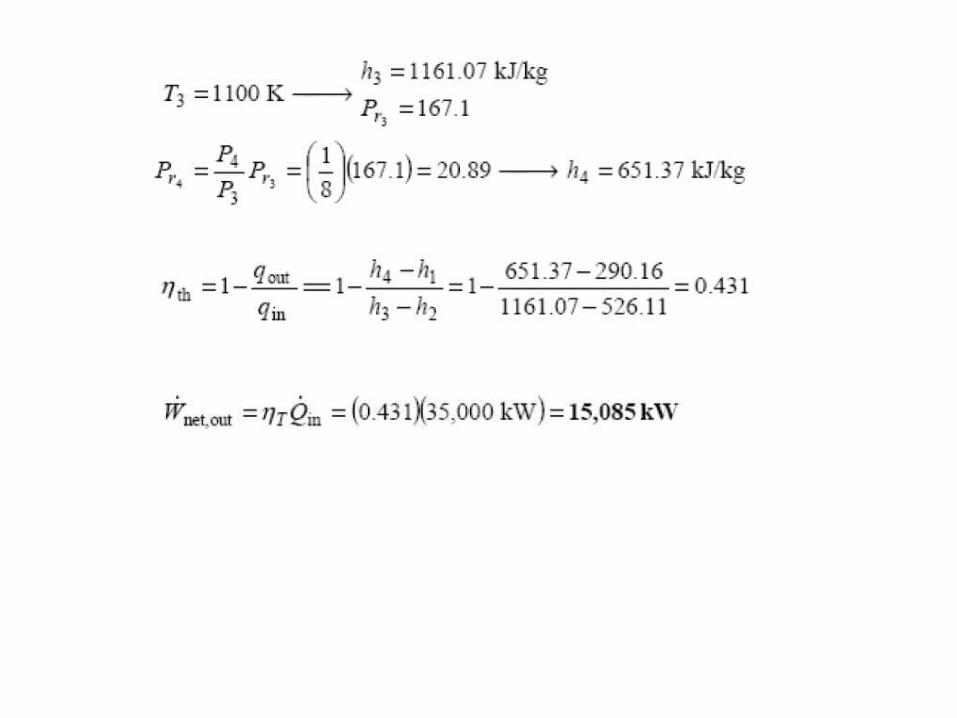
A stationary gas-turbine power plant operates on a simple ideal Brayton cycle with air as the working fluid. The air enters the compressor at 95 kPa and 290 K and the turbine at 760 kPa and 1100 K. Heat is transferred to air at a rate of 35,000 kW. Determine the power delivered by this planta) Assuming constant specific heats at room temperatureb) Accounting for the variation of specific heats with temperature
Assumptions :1 steady operating condition exists. 2 The air-standard assumptions are applicable.
3 Kinetic and potential energy changes are negligible.4 Air is an ideal gas.
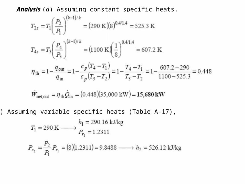
Analysis (a) Assuming constant specific heats,
(b) Assuming variable specific heats (Table A-17),

A steam power plant operates on a simple ideal Rankine cycle between thespecified pressure limits of 9 MPa and 15 kPa. The mass flow rate of steamthrough the cycle is 35 kg/s. The moisture content of the steam at theturbine exit is not to exceed 10 %. Show the cycle on a T-s diagram withrespect to saturation lines, and determine:
(a) The minimum turbine inlet temperature(b) the rate of heat input in the boiler(c) The thermal efficiency of the cycle
Assumptions:1 Steady operating condition exists. 2 Kinetic and potential energy changes are negligible.

Analysis (a) From the steam tables (Tables A-4, A-5, and A-6)

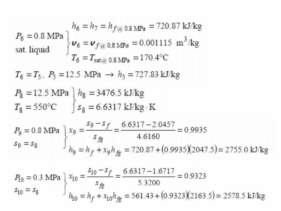
Consider an ideal steam regenerative Rankine cycle with two feedwater heaters, one closed and one open. Steam enters the turbine at 12.5 MPa and 550oC and exhaust to the condenser at 10 kPa. Steam is extracted from the turbine at 0.8 MPa from closed feedwater heater and at 0.3 MPa for the open one. The feedwater is heated to the condensation temperature of the extracted steam leaves the closed feedwater heater. The extracted steam leaves the closed feedwater heater as a saturated liquid which is subsequently throttled to the open feedwater heater. Show the cycle on a T-s diagram with respect to saturation lines, and determine:
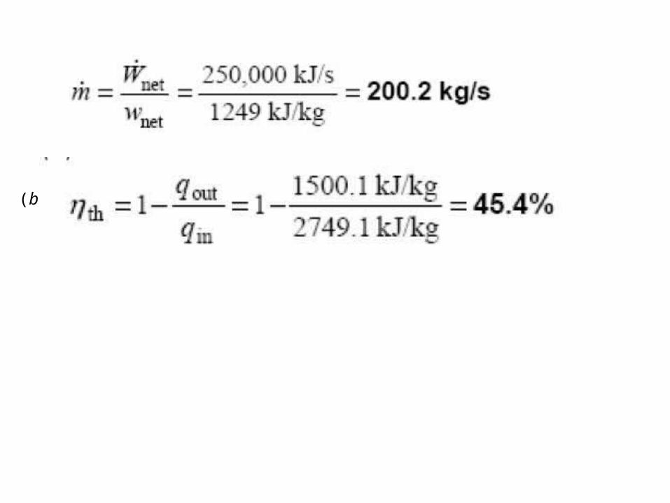
a) The mass flow rate of steam through the boiler for a net power output
of 250MW,b) the thermal efficiency of the cycle.


Assumptions:1 Steady operating conditions exist. 2 Kinetic and potential energy changes are negligible.

Analysis (a) From the steam tables (Tables A-4, A-5, and A-6)

The fraction of steam extracted is determined from the steady-flow energybalance equation applied to the feedwater heaters. Noting that 0
..
PEKEWQ
where y is the fraction of steam extracted from the turbine
5
10
m
m Solving for y:
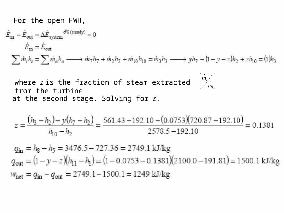
For the open FWH,
5
9
m
mwhere z is the fraction of steam extracted from the turbine
at the second stage. Solving for z,
(b)
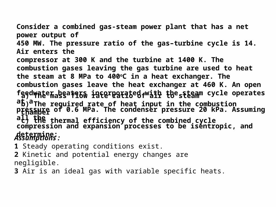
Consider a combined gas-steam power plant that has a net power output of450 MW. The pressure ratio of the gas–turbine cycle is 14. Air enters thecompressor at 300 K and the turbine at 1400 K. The combustion gases leaving the gas turbine are used to heat the steam at 8 MPa to 400oC in a heat exchanger. The combustion gases leave the heat exchanger at 460 K. An open feedwater heaters incorporated with the steam cycle operates at apressure of 0.6 MPa. The condenser pressure 20 kPa. Assuming all thecompression and expansion processes to be isentropic, and determine:
a) The mass flow rate ratio of air to steamb) The required rate of heat input in the combustion chamberc) the thermal efficiency of the combined cycle
Assumptions :1 Steady operating conditions exist. 2 Kinetic and potential energy changes are negligible. 3 Air is an ideal gas with variable specific heats.
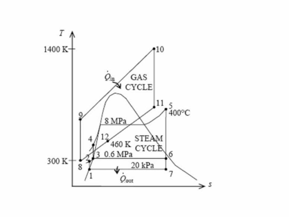

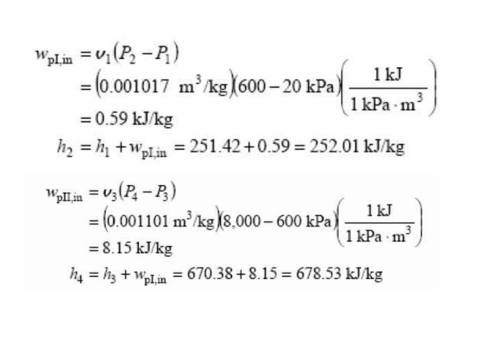
Analysis (a) The analysis of gas cycle yields (Table A-17)
From the steam tables (Tables A-4, A-5, A-6)

0
PEKEWQNoting that for the heat exchanger, the steady-flow
energy balance equation yields

0
PEKEWQNoting that for the open FWH, the steady-flow energy balance equation yields
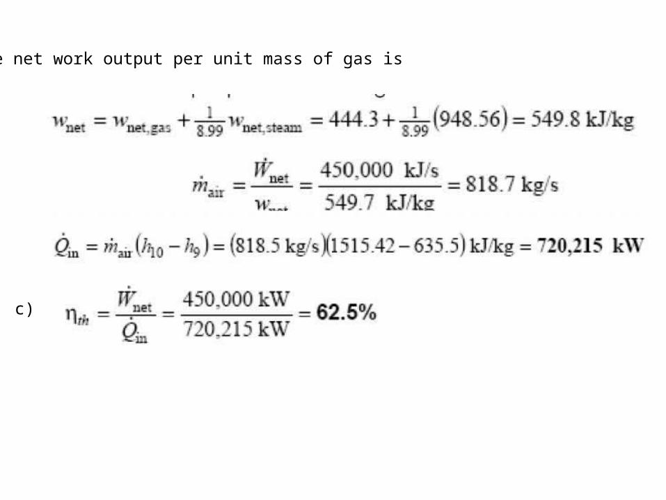
The net work output per unit mass of gas is
c)