UNIT 3 Intermediate elements. Instrumentation Amplifier Instrumentation amplifier is used to enhance...
112
UNIT 3 Intermediate elements
-
Upload
june-spencer -
Category
Documents
-
view
241 -
download
0
Transcript of UNIT 3 Intermediate elements. Instrumentation Amplifier Instrumentation amplifier is used to enhance...
UNIT 3
Intermediate elements
Instrumentation Amplifier
• Instrumentation amplifier is used to enhance the signal strength of the transducers output to the desirable level by amplification and make it suitable for further processing .
• The instrumentation amplifier is a dedicated differential amplifier with selectable gain (with linearity and accuracy) , high stability, high CMRR, with extremely high input impedance and low output impedance.
Instrumentation Amplifier• The instrumentation amplifier is a closed loop device
with carefully set gain. Its gain can be precisely set by a single internal or external resistor.
• The OPAMP itself is an open loop device with some very large (but variable) gain.
• This allows the instrumentation amplifier to be optimized for its role as signal conditioner of low level (often d.c.) signals in large amounts of noise. The high common mode rejection makes this amplifier very useful in recovering small signals buried in large common-mode offsets and noise.
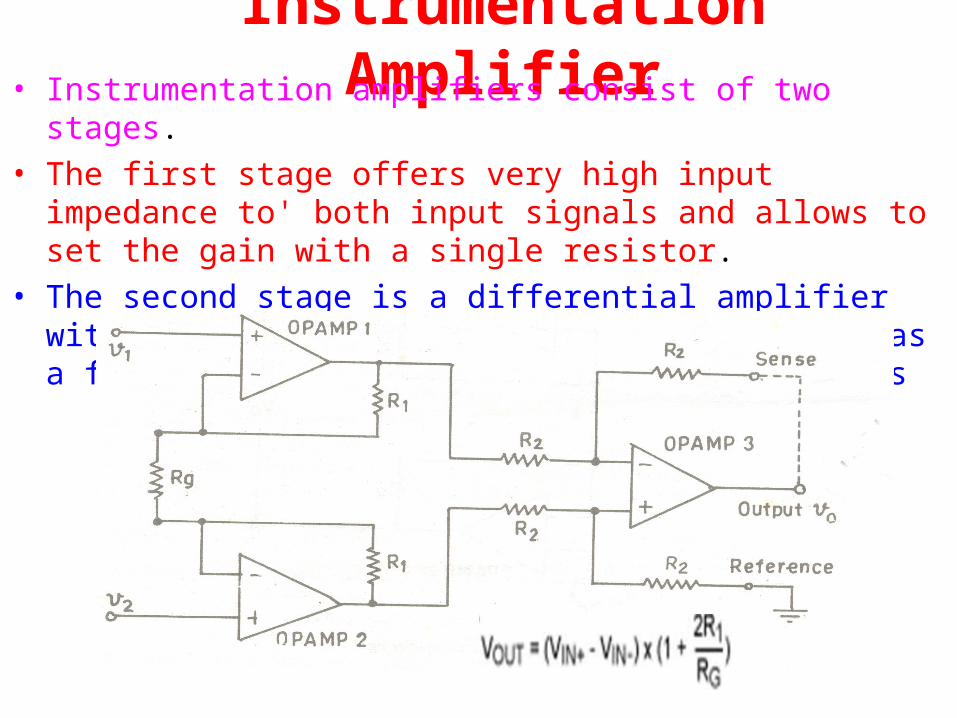
Instrumentation Amplifier• Instrumentation amplifiers consist of two stages. • The first stage offers very high input impedance to' both input signals
and allows to set the gain with a single resistor. • The second stage is a differential amplifier with negative feedback,
produces the output as a function of the differential input voltages
Instrumentation Amplifier
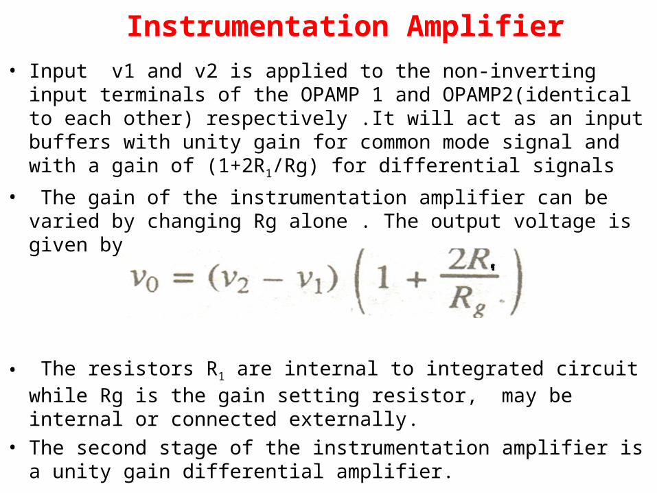
• Input v1 and v2 is applied to the non-inverting input terminals of the OPAMP 1 and OPAMP2(identical to each other) respectively .It will act as an input buffers with unity gain for common mode signal and with a gain of (1+2R1/Rg) for differential signals
• The gain of the instrumentation amplifier can be varied by changing Rg alone . The output voltage is given by
• The resistors R1 are internal to integrated circuit while Rg is the gain setting resistor, may be internal or connected externally.
• The second stage of the instrumentation amplifier is a unity gain differential amplifier.

Isolation Amplifier• Isolation amplifiers provides an electrical isolation to the output
from input and hence protect system from common mode voltages, unexpected short circuit etc.
• Isolation methods .1)A transformer -isolated amplifier ( Transformer coupling of a high-frequency carrier signal
between input and output)2) An optically-isolated amplifier (modulates current through an LED optocoupler).
3)Capacitor isolated Amplifier (capacitors are used to couple a modulated high-frequency
carrier)
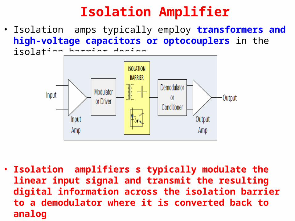
Isolation Amplifier• Isolation amps typically employ transformers and high-voltage
capacitors or optocouplers in the isolation barrier design
• Isolation amplifiers s typically modulate the linear input signal and transmit the resulting digital information across the isolation barrier to a demodulator where it is converted back to analog
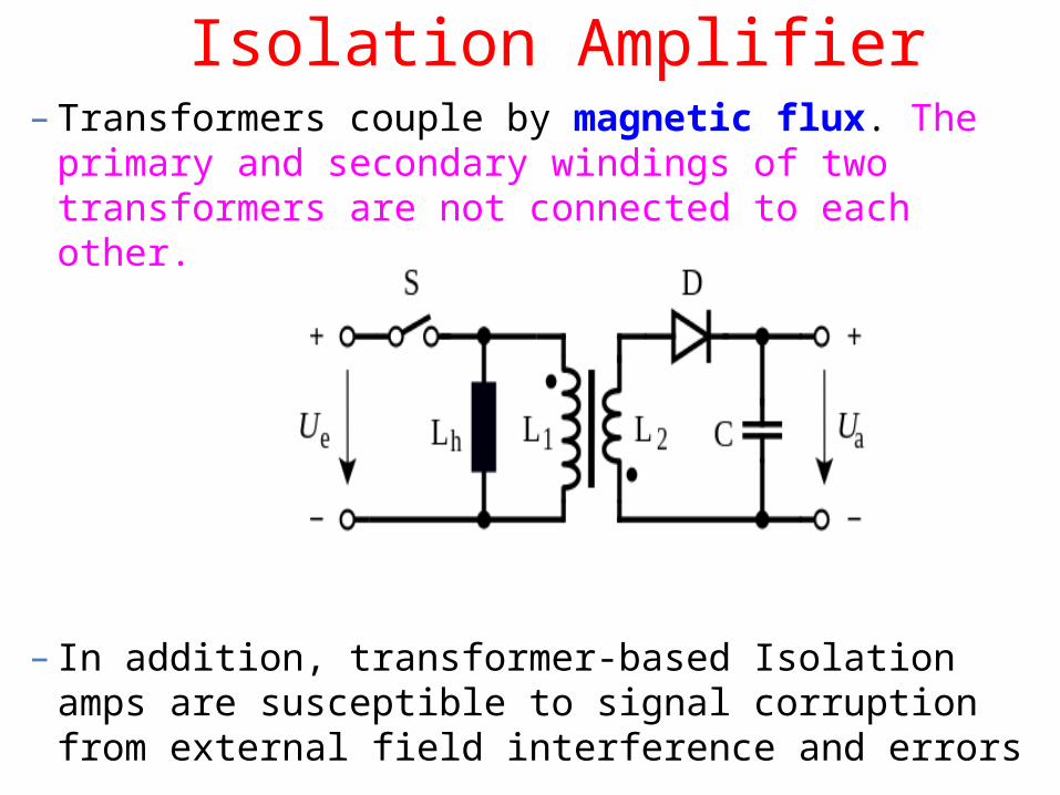
Isolation Amplifier– Transformers couple by magnetic flux. The primary and
secondary windings of two transformers are not connected to each other.
– In addition, transformer-based Isolation amps are susceptible to signal corruption from external field interference and errors
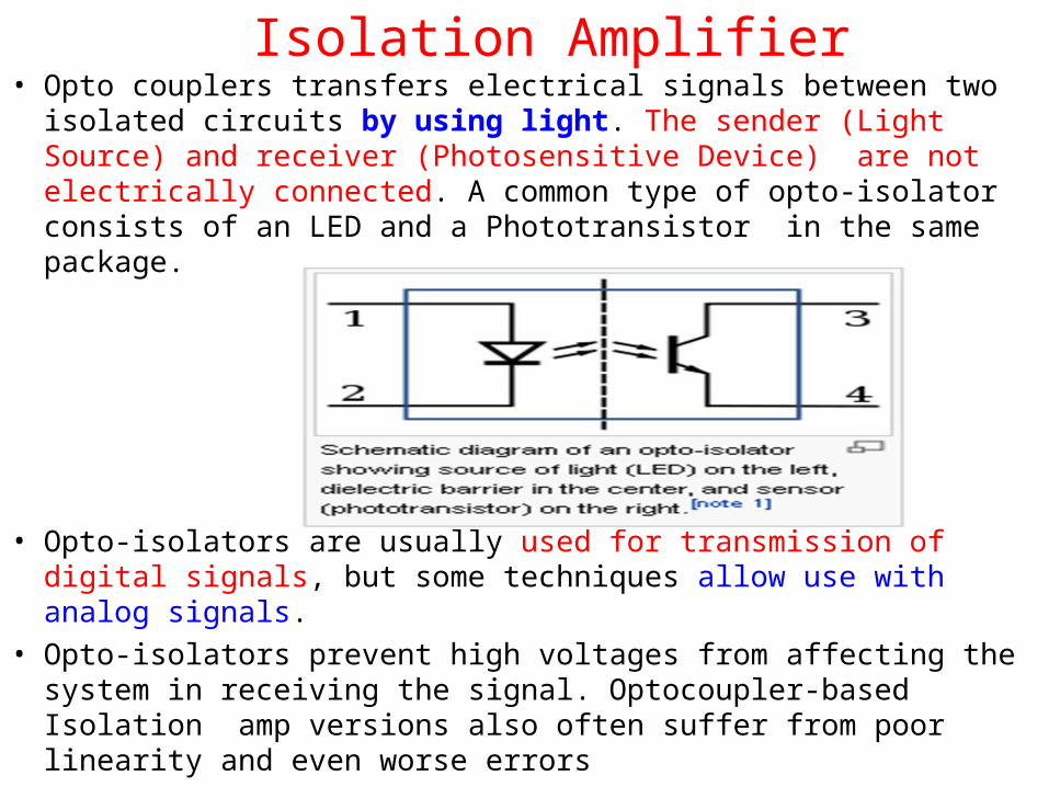
Isolation Amplifier• Opto couplers transfers electrical signals between two isolated
circuits by using light. The sender (Light Source) and receiver (Photosensitive Device) are not electrically connected. A common type of opto-isolator consists of an LED and a Phototransistor in the same package.
• Opto-isolators are usually used for transmission of digital signals, but some techniques allow use with analog signals.
• Opto-isolators prevent high voltages from affecting the system in receiving the signal. Optocoupler-based Isolation amp versions also often suffer from poor linearity and even worse errors
Isolation Amplifier
• Capacitors allow alternating current to flow, but block direct current . They couple ac signals between circuits at different direct voltages.
April 18, 2023 11
Bridges• Bridges offer an attractive alternative for measuring small
resistance changes accurately.
• To measure parameters R, L, C, f, Q (Quality factor of a coil) and ‘D’ (Dissipation factor of a capacitor) of electronic circuits, bridge circuits are employed.
• The advantage with bridge-measuring circuits is that some errors which occur in measurements due to parasitic values, temperature effects, errors due to improper grounding and shielding can be eliminated.
April 18, 2023 12
Bridges• DC bridges can measure resistance R
accurately over wide ranges.
• AC bridges can be used to determine the unknown values of inductor L and capacitor C and even R and frequency f also.
• Even parameters like quality factor of a coil Q, dissipation factor D of a capacitor can also be measured using AC bridges in addition to frequency.

April 18, 2023 13
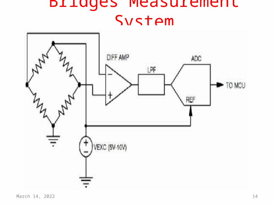
Bridges• The bridge circuit works as a pair of two-
component voltage dividers connected across the same source voltage, with a null-detector meter movement connected between them to indicate a condition of “balance” at zero volts:
April 18, 2023 14
Bridges Measurement System

15
DC Bridges

April 18, 2023 16
DC bridges• DC bridges are used to determine the unknown conducting
value. • Wheatstone bridge and Kelvin double bridge are the two
types in this category.
• AC bridges can also be used for resistance measurements, but they are used to determine inductance, capacitance, impedance, admittance, or the frequency of the AC input.
• The D.C bridges use the D.C voltages as the excitation voltage while the A.C bridges use the alternating voltage as the excitation voltage.
April 18, 2023 17
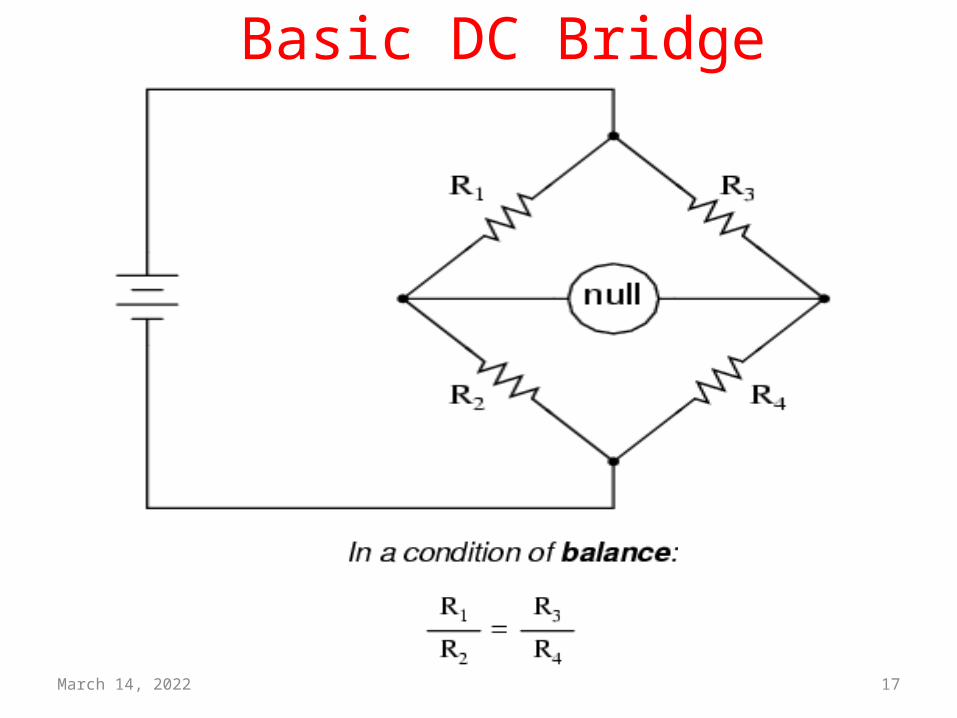
Basic DC Bridge
April 18, 2023 18
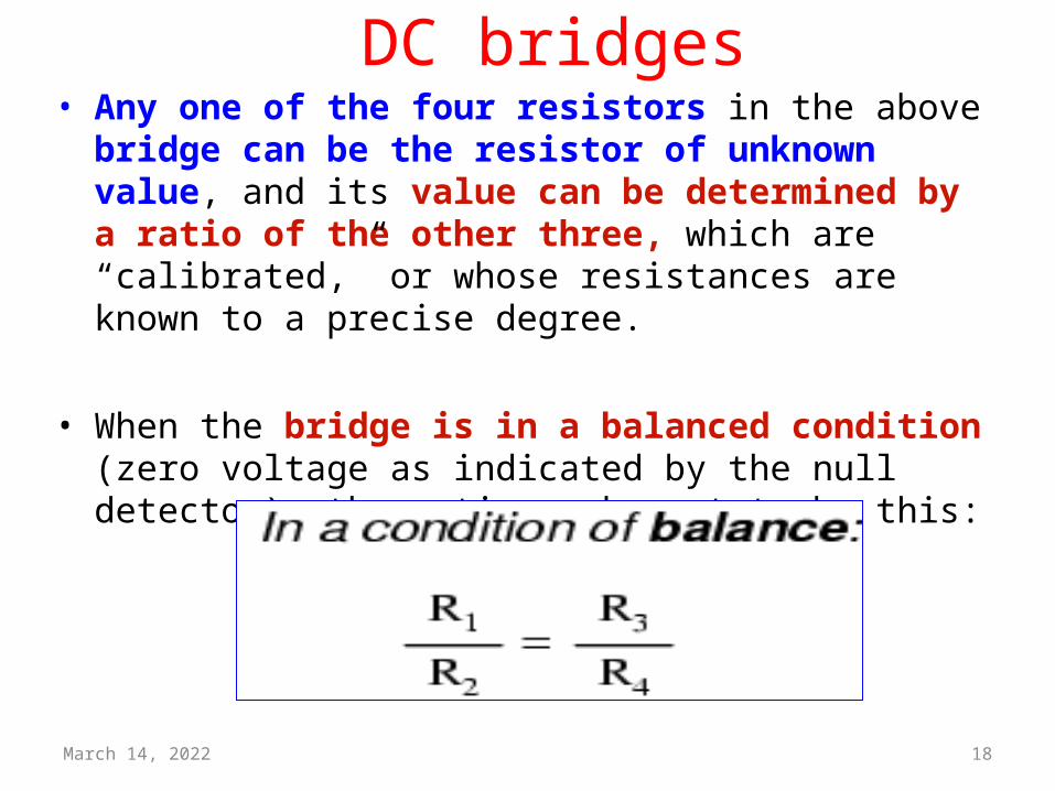
DC bridges• Any one of the four resistors in the above bridge can be the
resistor of unknown value, and its value can be determined by a ratio of the other three, which are “calibrated,” or whose resistances are known to a precise degree.
• When the bridge is in a balanced condition (zero voltage as indicated by the null detector), the ratio works out to be this:

April 18, 2023 19
Application of DC bridges

April 18, 2023 20DEEPAK.P
Wheaston’s DC Bridge
April 18, 2023 21
Wheaston’s DC bridges• A bridge measures resistance indirectly by
comparison with a similar resistance.
• All the resistances are nominally equal, but one of them (the sensor) is variable by an amount of change in R.
April 18, 2023 22
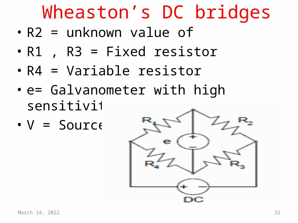
Wheaston’s DC bridges• R2 = unknown value of• R1 , R3 = Fixed resistor• R4 = Variable resistor• e= Galvanometer with high sensitivity• V = Source
April 18, 2023 23
Wheaston’s bridges
April 18, 2023 24
Wheaston’s bridges
April 18, 2023 25
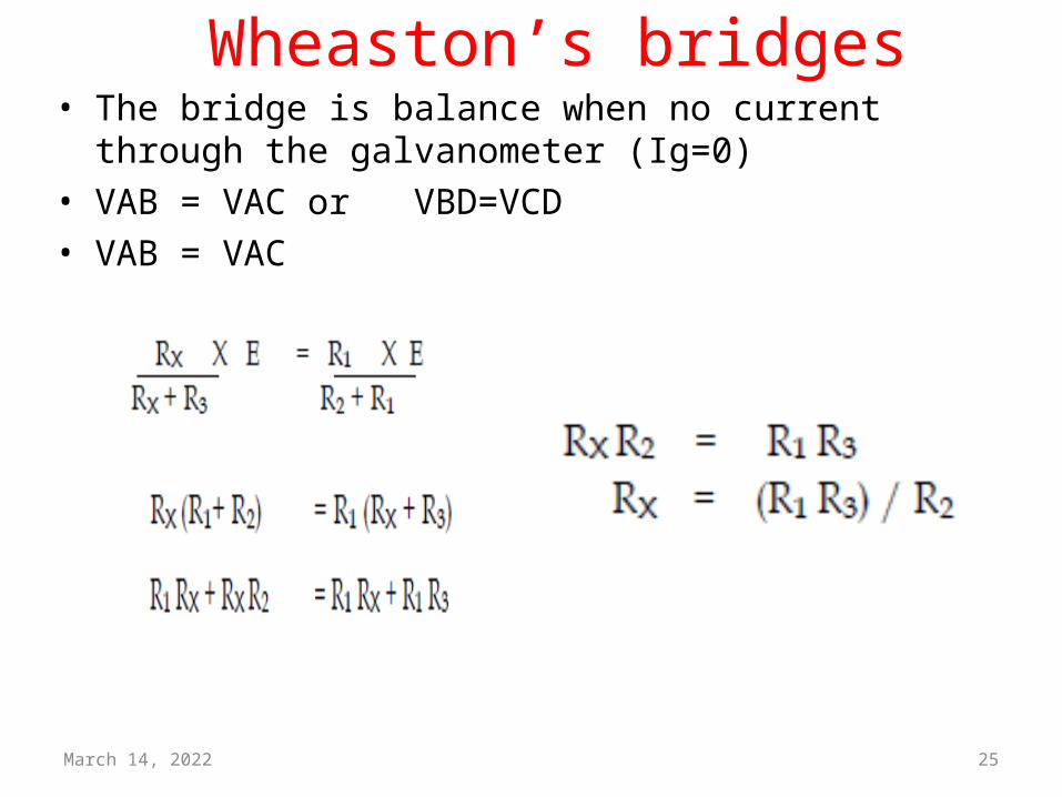
Wheaston’s bridges• The bridge is balance when no current through the
galvanometer (Ig=0)• VAB = VAC or VBD=VCD• VAB = VAC
April 18, 2023 26
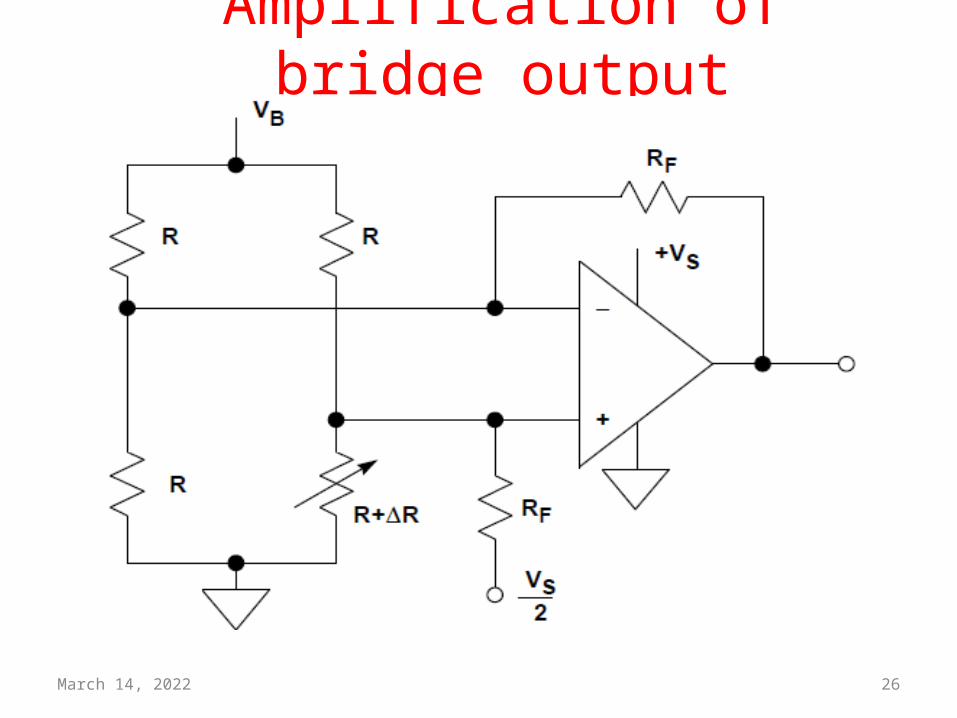
Amplification of bridge output

April 18, 2023 27DEEPAK.P
Guarded Wheaston’s DC Bridge
April 18, 2023 28
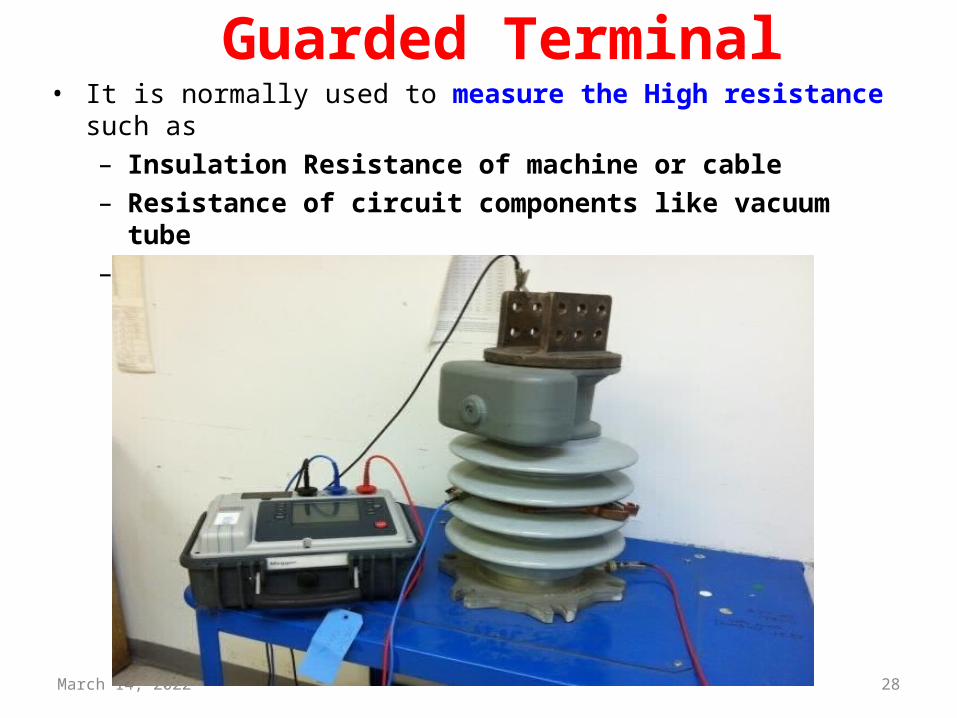
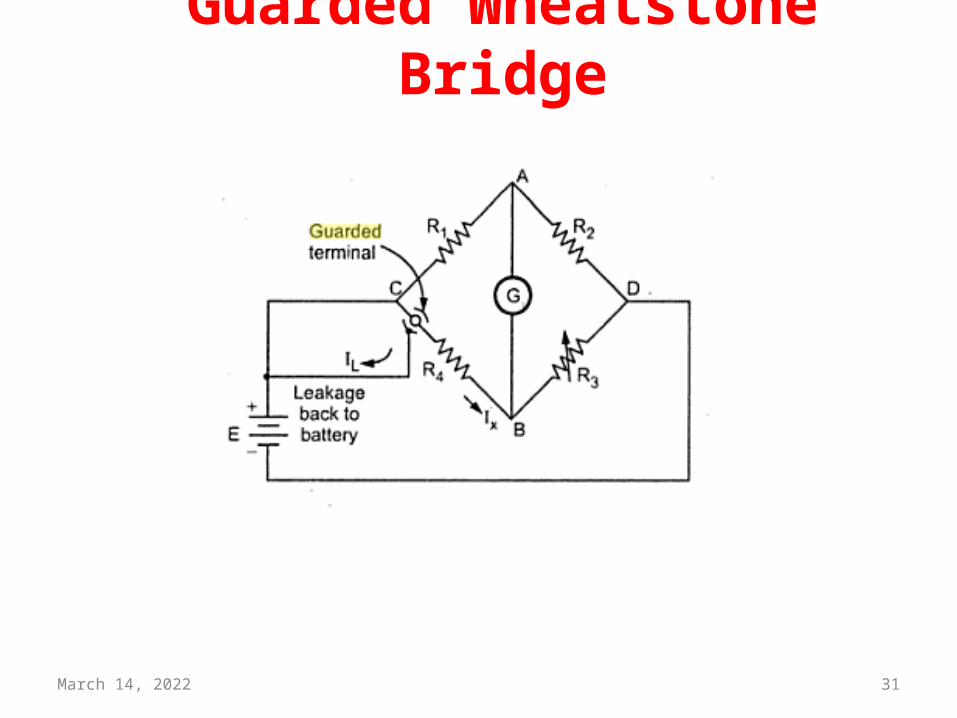
Guarded Terminal• It is normally used to measure the High resistance such as
– Insulation Resistance of machine or cable– Resistance of circuit components like vacuum tube– Leakage resistance of a capacitor
April 18, 2023 29
Guarded Wheatstone Bridge• It is very difficult to measure such resistance because of the
very high resistances ,small current flowing in the measuring circuits.
• It is very difficult to sense these small current.
• Another difficulty is the Presence of leakage currents
• This leakage currents makes errors
• This error can be avoid by using guard circuits
April 18, 2023 30
Guarded Terminal• The function of the Guard is to act as a shunt circuit for
parallel leakage paths in the test item• With it, one or more parallel current paths can be removed
from the measurement, thereby permitting a precise reading of the remaining path.
April 18, 2023 31
Guarded Wheatstone Bridge
April 18, 2023 32
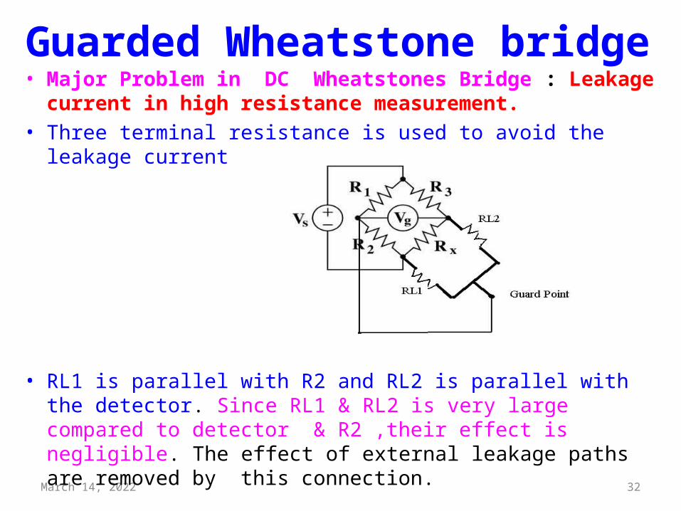
• Major Problem in DC Wheatstones Bridge : Leakage current in high resistance measurement.
• Three terminal resistance is used to avoid the leakage current
• RL1 is parallel with R2 and RL2 is parallel with the detector. Since RL1 & RL2 is very large compared to detector & R2 ,their effect is negligible. The effect of external leakage paths are removed by this connection.
Guarded Wheatstone bridge
April 18, 2023 33
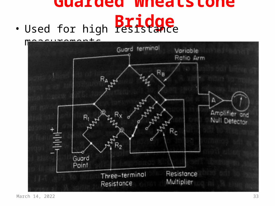
Guarded Wheatstone Bridge• Used for high resistance measurements

April 18, 2023 34DEEPAK.P
AC Bridges

April 18, 2023 35
AC Bridges• AC bridges are often used to measure accurately the
value of an unknown impedance, for example, self/mutual inductance of inductors or capacitance of capacitors.
• Most of the AC bridges are based on a generalized Wheatstone Bridge circuit.
April 18, 2023 36
AC bridges Vs Dc Bridge

April 18, 2023 37
AC Bridges
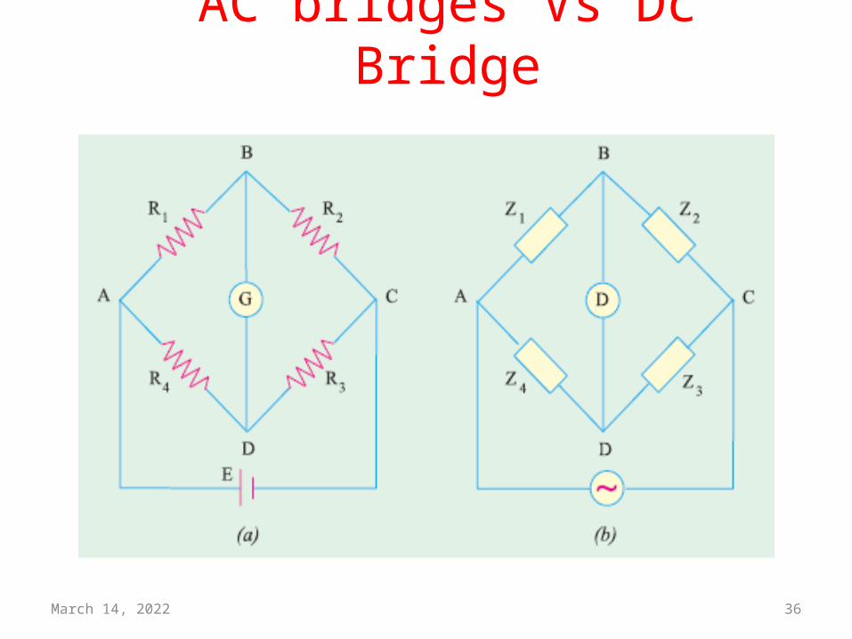
ZAZD=ZBZC
April 18, 2023 38
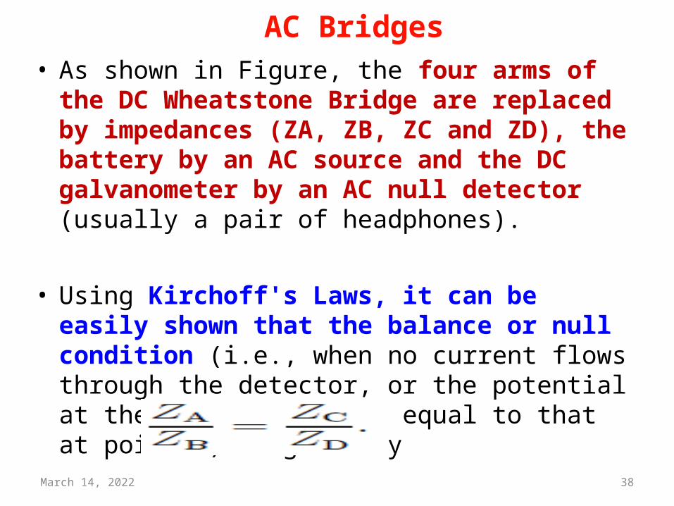
AC Bridges• As shown in Figure, the four arms of the DC
Wheatstone Bridge are replaced by impedances (ZA, ZB, ZC and ZD), the battery by an AC source and the DC galvanometer by an AC null detector (usually a pair of headphones).
• Using Kirchoff's Laws, it can be easily shown that the balance or null condition (i.e., when no current flows through the detector, or the potential at the point P becomes equal to that at point R) is given by
April 18, 2023 39
AC bridges• The various types of A.C Bridges are,
• Inductance Comparison Bridge• Capacitance Comparison Bridge• Maxwell’s Bridge• Hay’s Bridge• Anderson Bridge• Wien Bridge• Owen's bridge • Shering Bridge

April 18, 2023 40DEEPAK.P
Owens Bridges
April 18, 2023 41
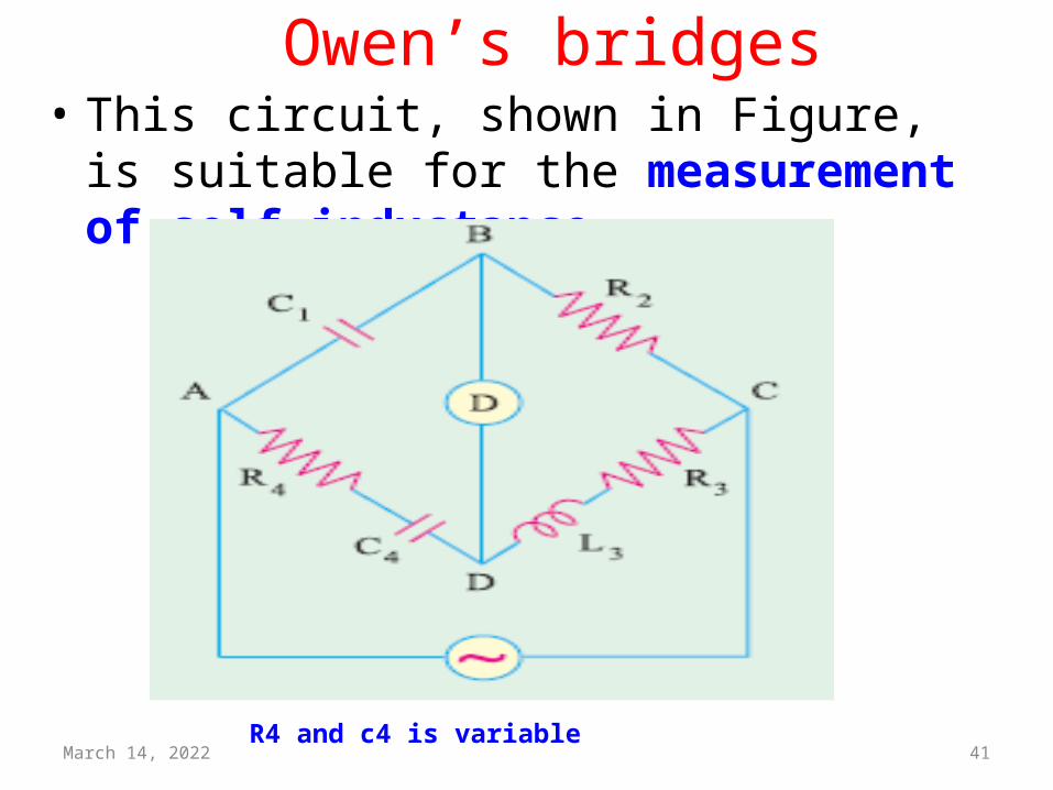
Owen’s bridges• This circuit, shown in Figure, is suitable for the
measurement of self-inductance.
R4 and c4 is variable
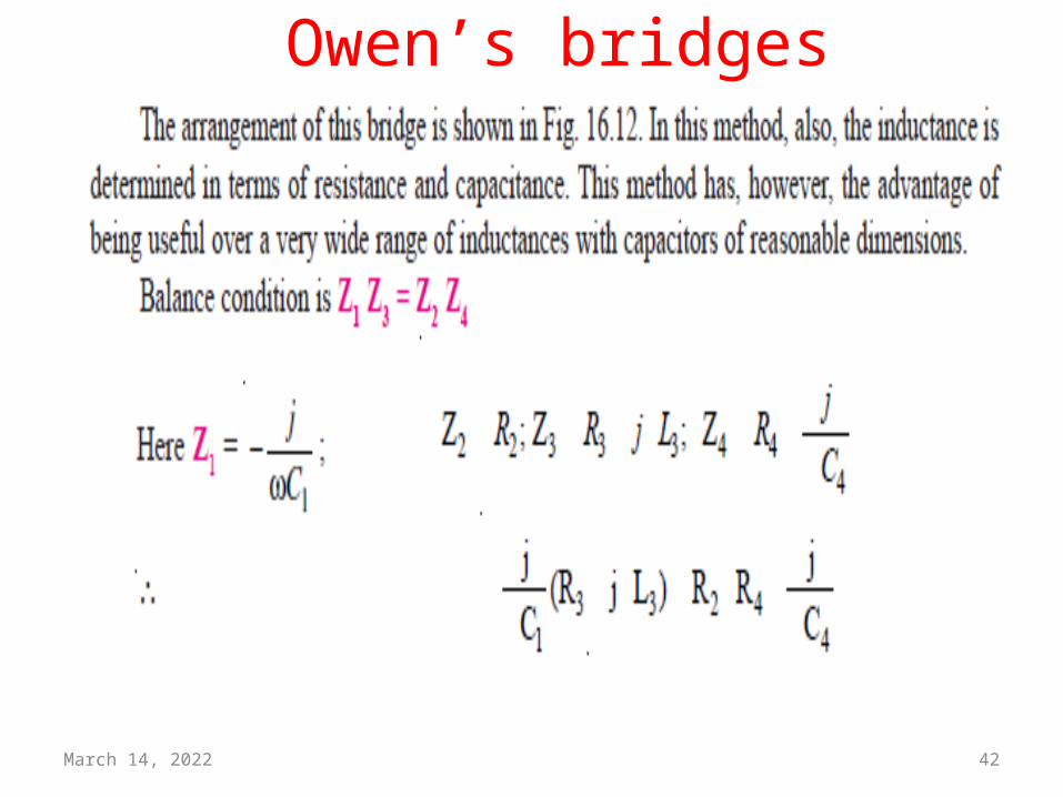
April 18, 2023 42
Owen’s bridges
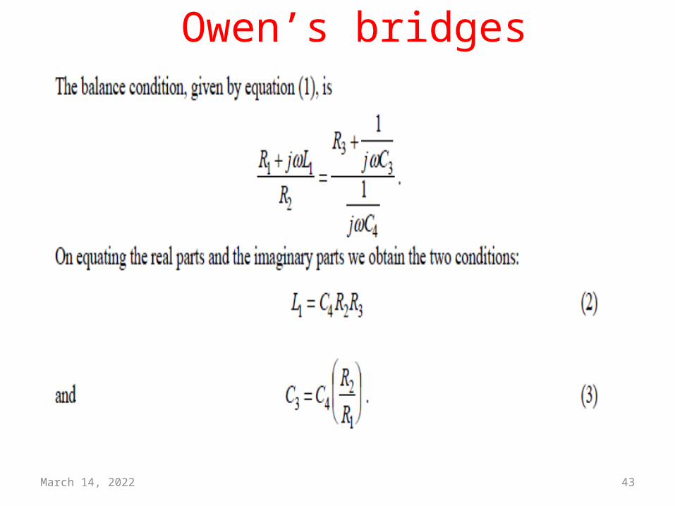
April 18, 2023 43
Owen’s bridges
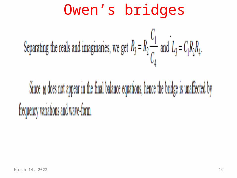
April 18, 2023 44
Owen’s bridges
April 18, 2023 45
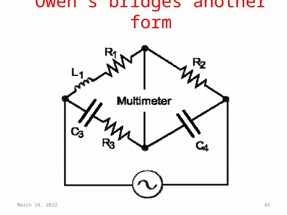
Owen’s bridges another form
April 18, 2023 46
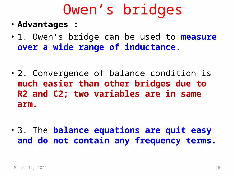
Owen’s bridges• Advantages :• 1. Owen’s bridge can be used to measure over
a wide range of inductance.
• 2. Convergence of balance condition is much easier than other bridges due to R2 and C2; two variables are in same arm.
• 3. The balance equations are quit easy and do not contain any frequency terms.

April 18, 2023 47
Owen’s bridges• Disadvantages :
• 1. The Owen’s bridge requires a variable capacitor that is expensive and makes its accuracy rather low.
• 2. The value of C2 tends to become rather large when measuring high Q coils.

April 18, 2023 48DEEPAK.P
Schering Bridge
April 18, 2023 49
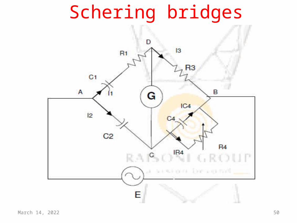
Schering bridges• The schering bridge is one of the most important
ac bridge used extensively for the measurement of capacitance.
• In schering bridge the arm 1 contains a series combination of the resistor and the capacitor and standard arm contain only one capacitor.
• In the balance condition of the bridge the sum of the phase angles of the arms 1and 4 is equal the sum of the phase angle of arms 2 and 3
April 18, 2023 50
Schering bridges
April 18, 2023 51
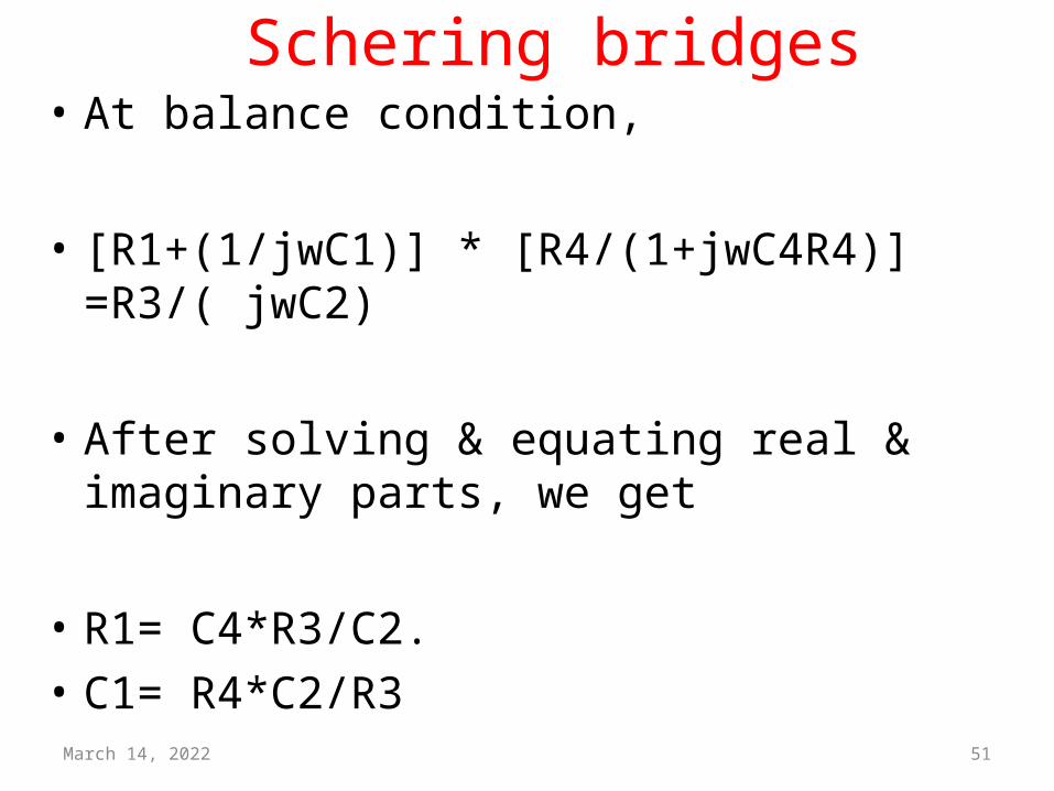
Schering bridges• At balance condition,
• [R1+(1/jwC1)] * [R4/(1+jwC4R4)] =R3/( jwC2)
• After solving & equating real & imaginary parts, we get
• R1= C4*R3/C2.• C1= R4*C2/R3
April 18, 2023 52
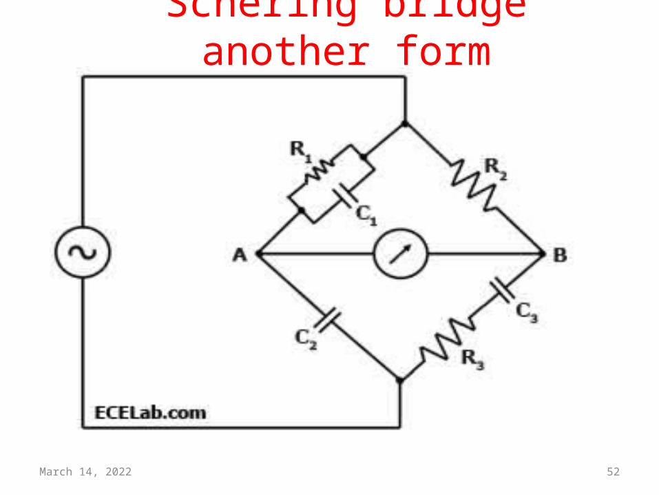
Schering bridge another form

April 18, 2023 53DEEPAK.P
Wein Bridges
April 18, 2023 54
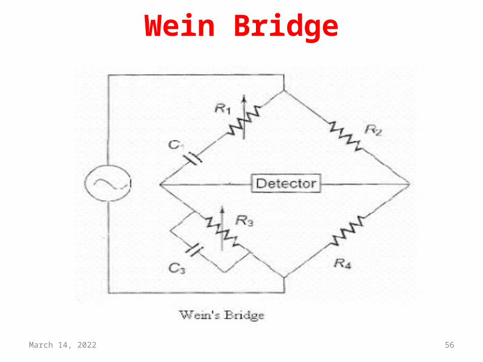
Wein Bridge• The Wien bridge is a type of bridge circuit that was developed
by Max Wien in 1891
• The bridge comprises four resistors and two capacitors.
• Wien Bridge has a series RC combination in one and a parallelcombination in the adjoining arm
• Wien's bridge is used for precision measurement of capacitance in terms of resistance and frequency
April 18, 2023 55
Wein Bridge• It was also used to measure audio
frequencies.
• The bridge is also used in a harmonic distortion analyzer, as a Notch filter, an in audio frequency and radio frequency oscillators as a frequency determine element.
April 18, 2023 56
Wein Bridge
April 18, 2023 57
Wein Bridge
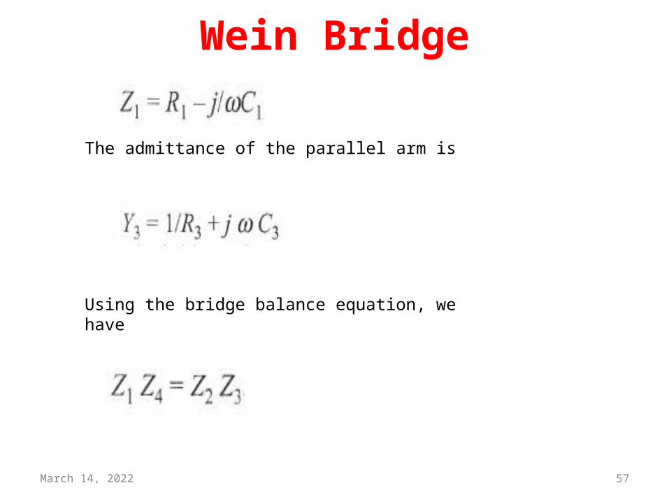
The admittance of the parallel arm is
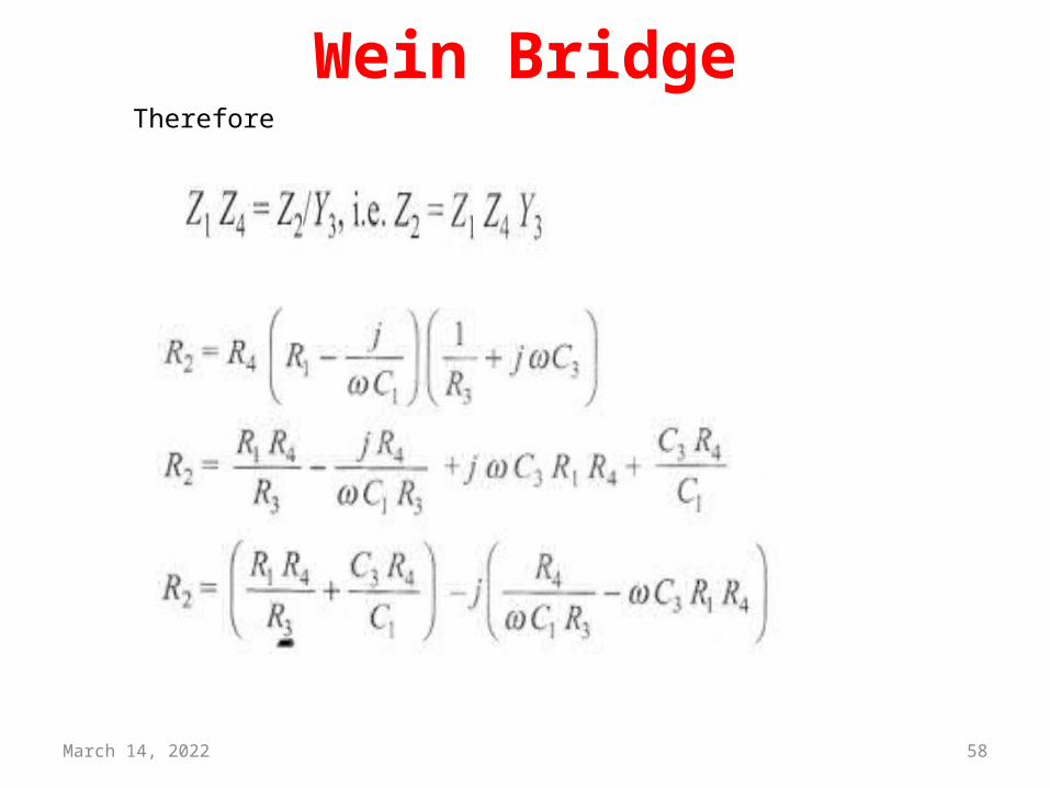
Using the bridge balance equation, we have
April 18, 2023 58
Wein BridgeTherefore
April 18, 2023 59
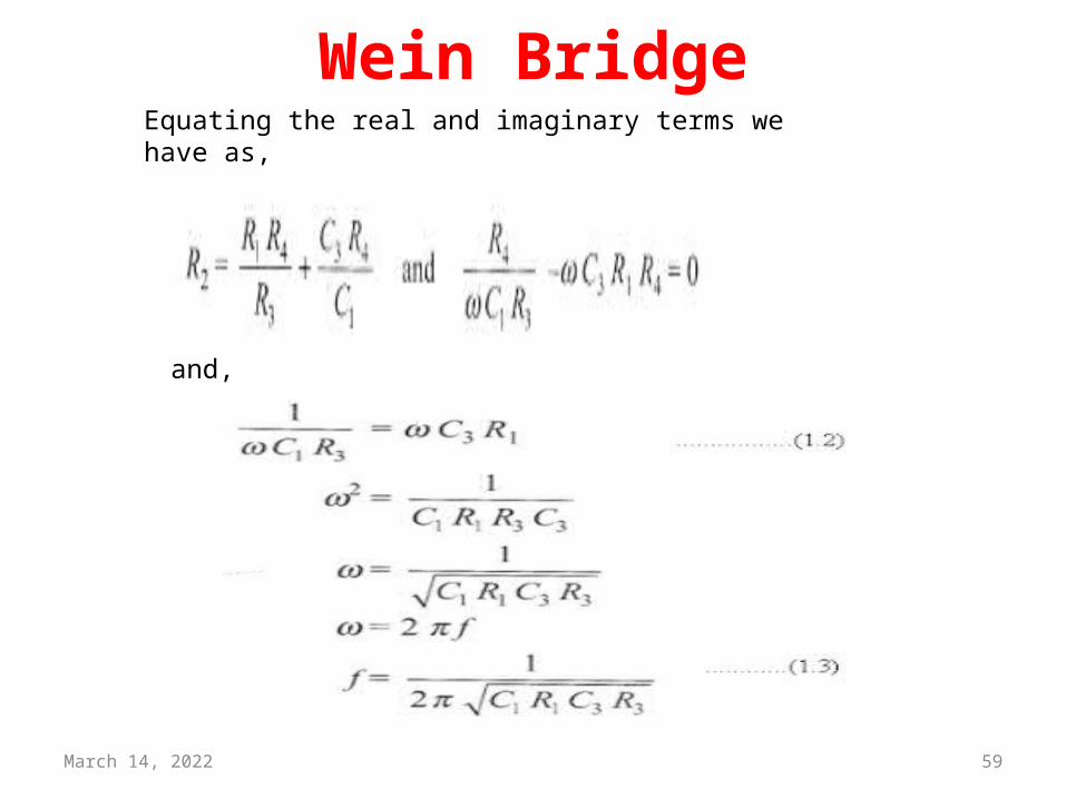
Wein BridgeEquating the real and imaginary terms we have as,
and,
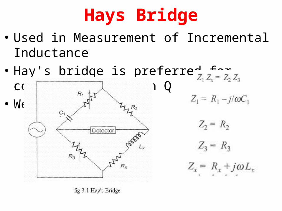
Hays Bridge• Used in Measurement of Incremental Inductance• Hay's bridge is preferred for coils with a high Q• We have
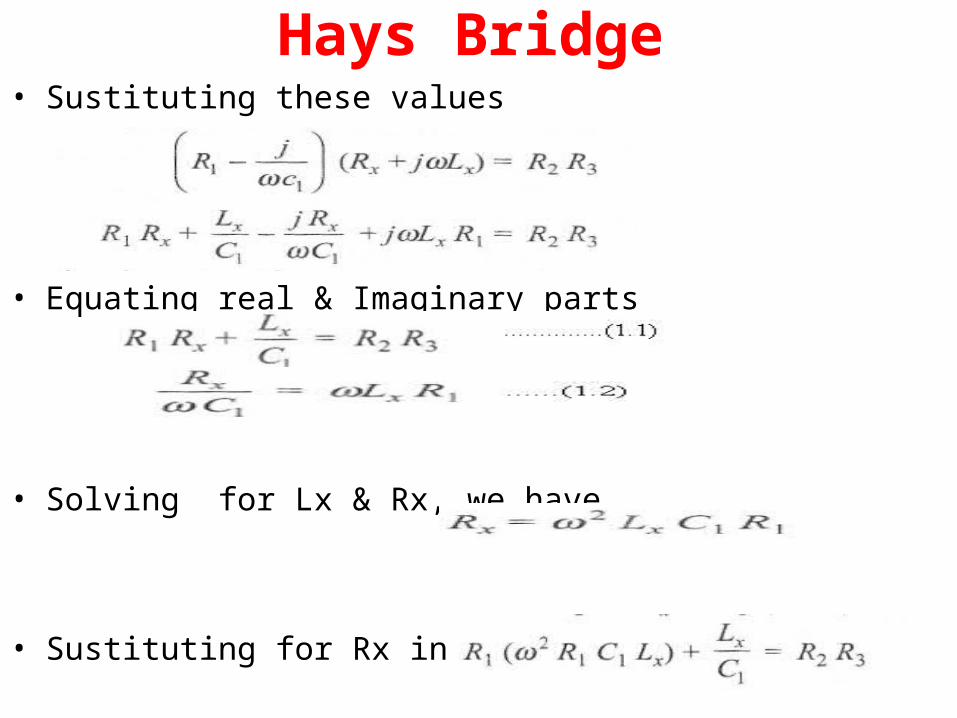
Hays Bridge• Sustituting these values
• Equating real & Imaginary parts
• Solving for Lx & Rx, we have
• Sustituting for Rx in eqn 1.1
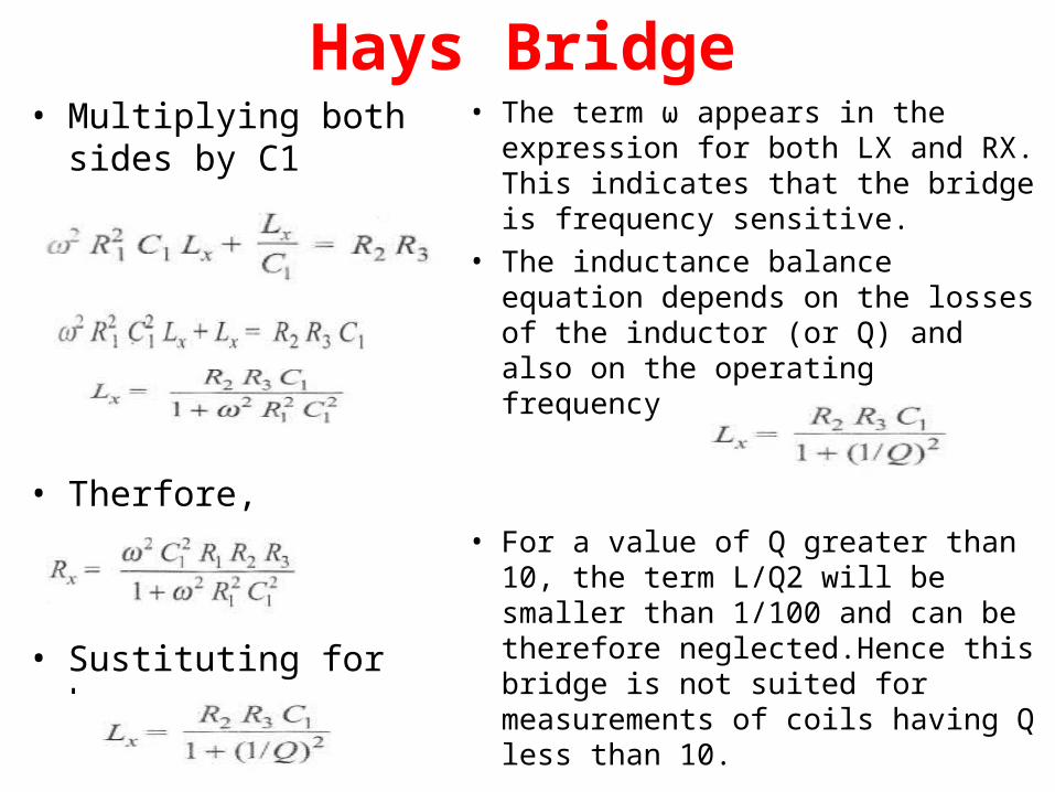
Hays Bridge• Multiplying both sides by
C1
• Therfore,
• Sustituting for Lx
• The term ω appears in the expression for both LX and RX. This indicates that the bridge is frequency sensitive.
• The inductance balance equation depends on the losses of the inductor (or Q) and also on the operating frequency.
• For a value of Q greater than 10, the term L/Q2 will be smaller than 1/100 and can be therefore neglected.Hence this bridge is not suited for measurements of coils having Q less than 10.

April 18, 2023 63DEEPAK.P
Wagner Ground
April 18, 2023 64
Stray Capacitance• Stray capacitance(one that develops between
wires ,conductors within the circuit.
• In electrical circuits, parasitic capacitance, stray capacitance is an unavoidable and usually unwanted capacitance that exists between the parts of an electronic component or circuit
April 18, 2023 65
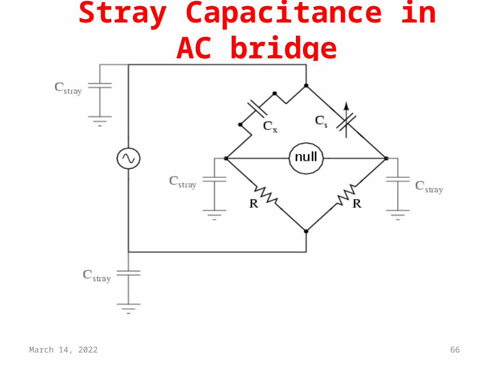
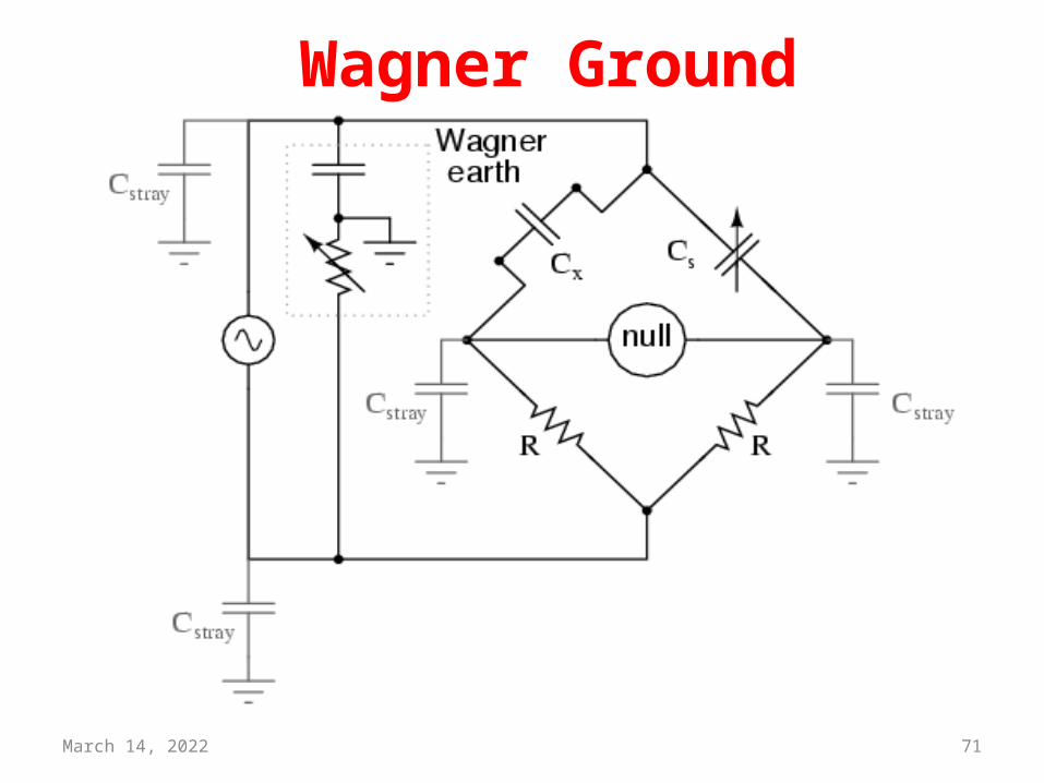
Wagner Ground• A potential problem in sensitive AC bridge circuits is that of
stray capacitance between either end of the null detector unit and ground (earth) potential.
• Because capacitances can “conduct” alternating current by charging and discharging, they form stray current paths to the AC voltage source which may affect bridge balance
• Stray capacitance to ground may introduce errors into the bridge.
April 18, 2023 66
Stray Capacitance in AC bridge
April 18, 2023 67
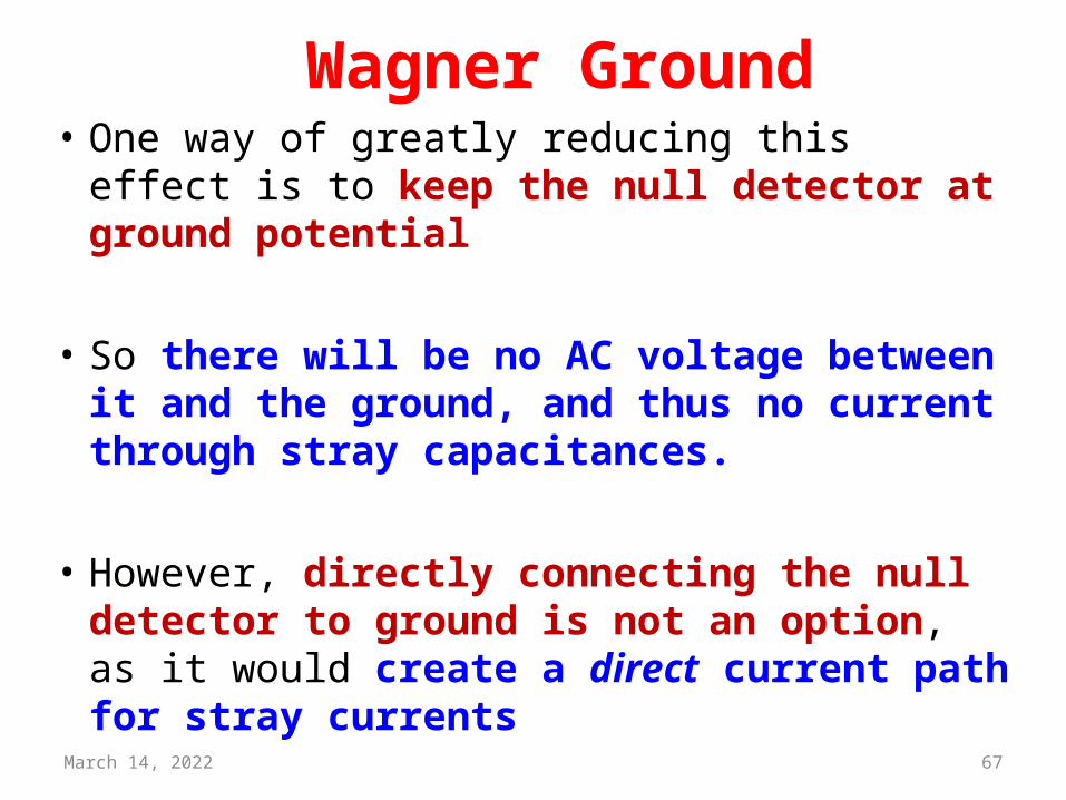
Wagner Ground• One way of greatly reducing this effect is to
keep the null detector at ground potential
• So there will be no AC voltage between it and the ground, and thus no current through stray capacitances.
• However, directly connecting the null detector to ground is not an option, as it would create a direct current path for stray currents
April 18, 2023 68
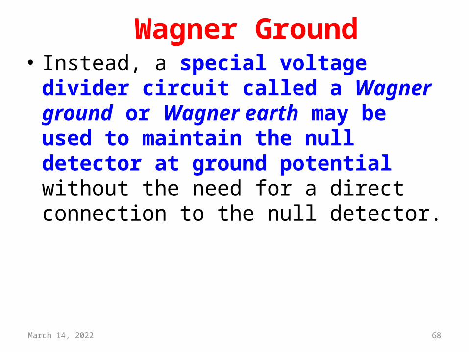
Wagner Ground• Instead, a special voltage divider circuit called
a Wagner ground or Wagner earth may be used to maintain the null detector at ground potential without the need for a direct connection to the null detector.
April 18, 2023 69
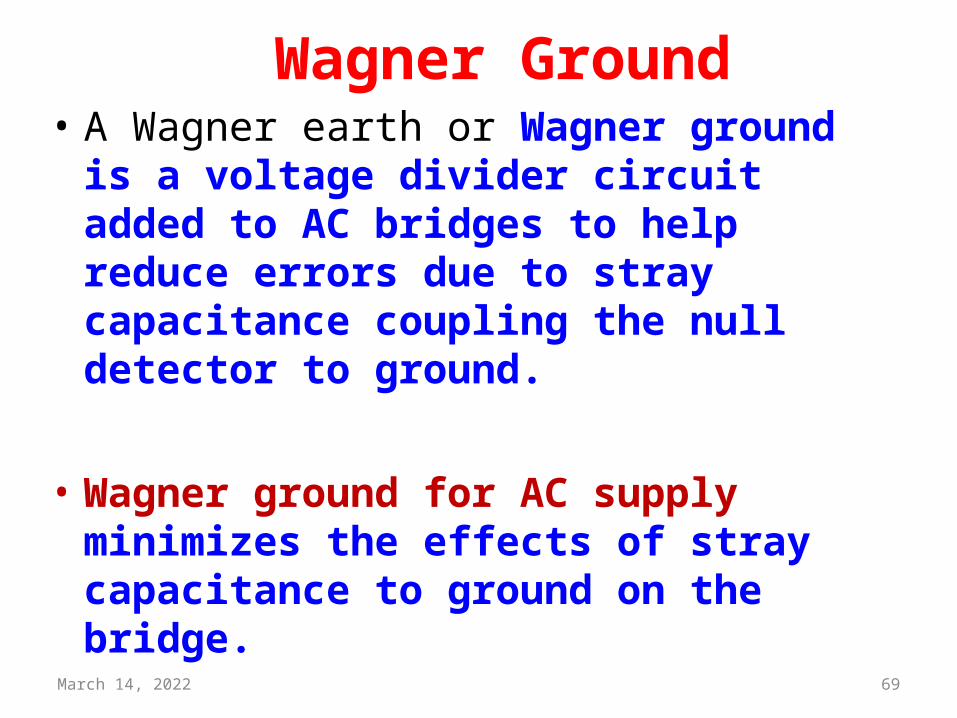
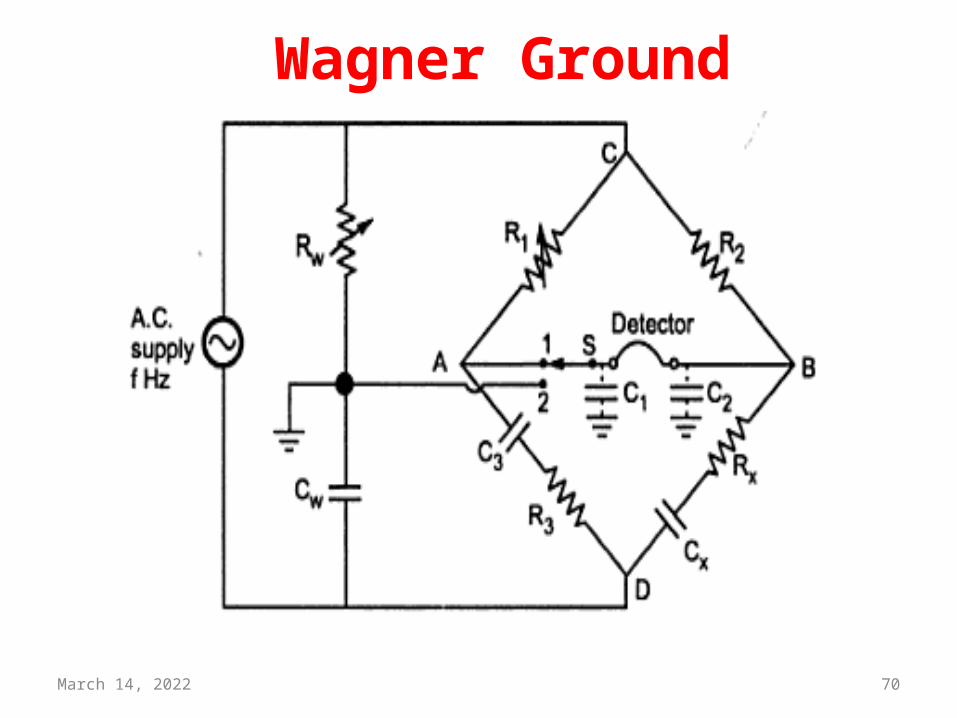
Wagner Ground• A Wagner earth or Wagner ground is a voltage
divider circuit added to AC bridges to help reduce errors due to stray capacitance coupling the null detector to ground.
• Wagner ground for AC supply minimizes the effects of stray capacitance to ground on the bridge.
April 18, 2023 70
Wagner Ground
April 18, 2023 71
Wagner Ground
Multiplexing• Whenever the bandwidth of a medium linking two Whenever the bandwidth of a medium linking two
devices devices is greater than the bandwidth needs of the is greater than the bandwidth needs of the devicesdevices, the link can be shared, the link can be shared
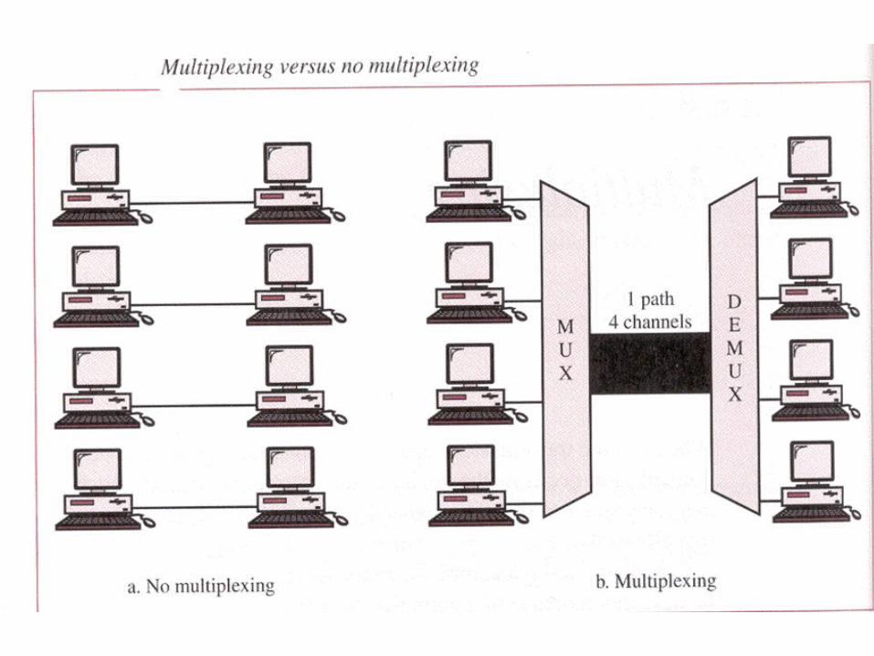
• Multiplexing is the set of techniques that allows the simultaneous transmission of multiple signals across a single data link.
• A Multiplexer (MUX) is a device that combines several signals into a single signal.
• A Demultiplexer (DEMUX) is a device that performs the inverse operation.
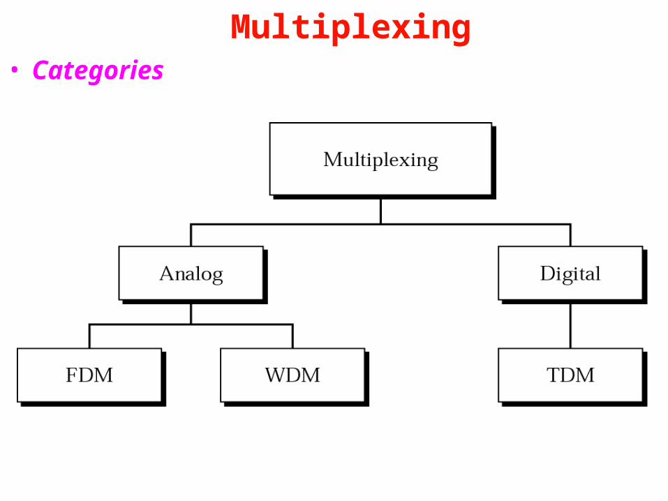
Multiplexing• Categories

Frequency-division Multiplexing (FDM)
• FDM is an analog multiplexing technique that combines signals.
• In FDM, signals generated by each device modulate different carrier frequencies by modifying the amplitude or frequency(AM/FM) of the carrier signal .
• These modulated signals re combined into a single composite signal that can be transported by the link.
• Commonly used in TV & Radio.
Frequency-division Multiplexing (FDM)
• Carrier frequencies are separated by enough bandwidth to accommodate the modulated signal.
• When channels are very close to one other, it leads to inter-channel cross talk .Channels must separated by strips of unused bandwidth (guard bands) to prevent signal overlapping.
• FDM cannot utilize the full capacity of the cable.
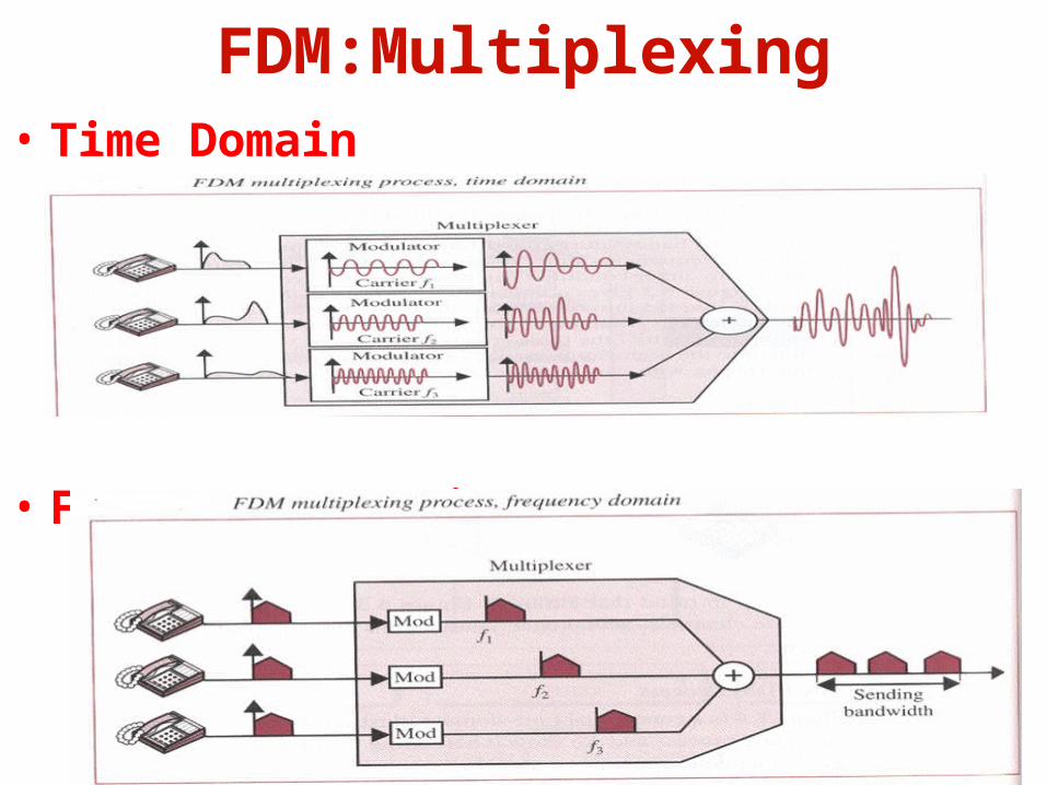
FDM:Multiplexing• Time Domain
• Frequency Domain
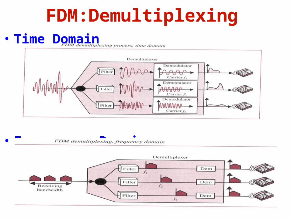
FDM:Demultiplexing• Time Domain
• Frequency Domain
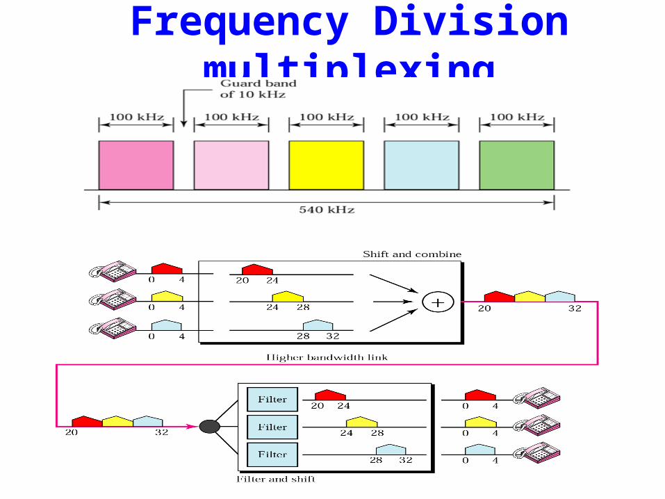
Frequency Division multiplexing
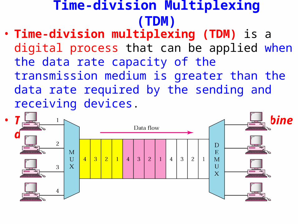
Time-division Multiplexing (TDM)• Time-division multiplexing (TDM) is a digital process that
can be applied when the data rate capacity of the transmission medium is greater than the data rate required by the sending and receiving devices.
• TDM is a digital multiplexing technique to combine data.
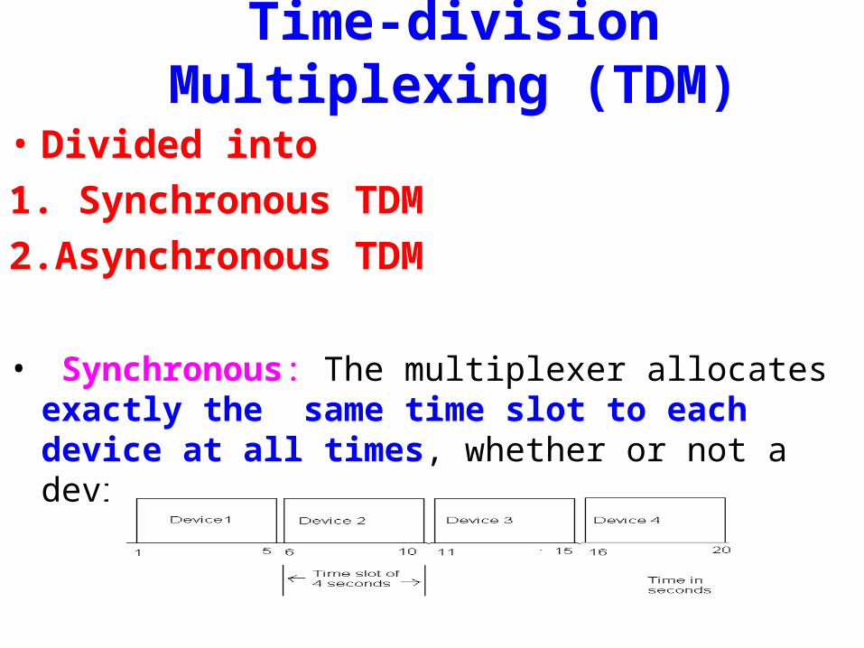
• Divided into 1. Synchronous TDM2.Asynchronous TDM
• Synchronous: The multiplexer allocates exactly the same time slot to each device at all times, whether or not a device has anything to transmit.
Time-division Multiplexing (TDM)
Synchronous TDM• Time slots are grouped into frames.
• A frame consists of a one complete cycle of time slots, including one or more slots dedicated to each sending device.
• Usually one or more synchronization bits are usually added to the beginning of each frame.
• These framing bits allows the demultiplexer to synchronize with the incoming stream so that it can separate the time slot accurately
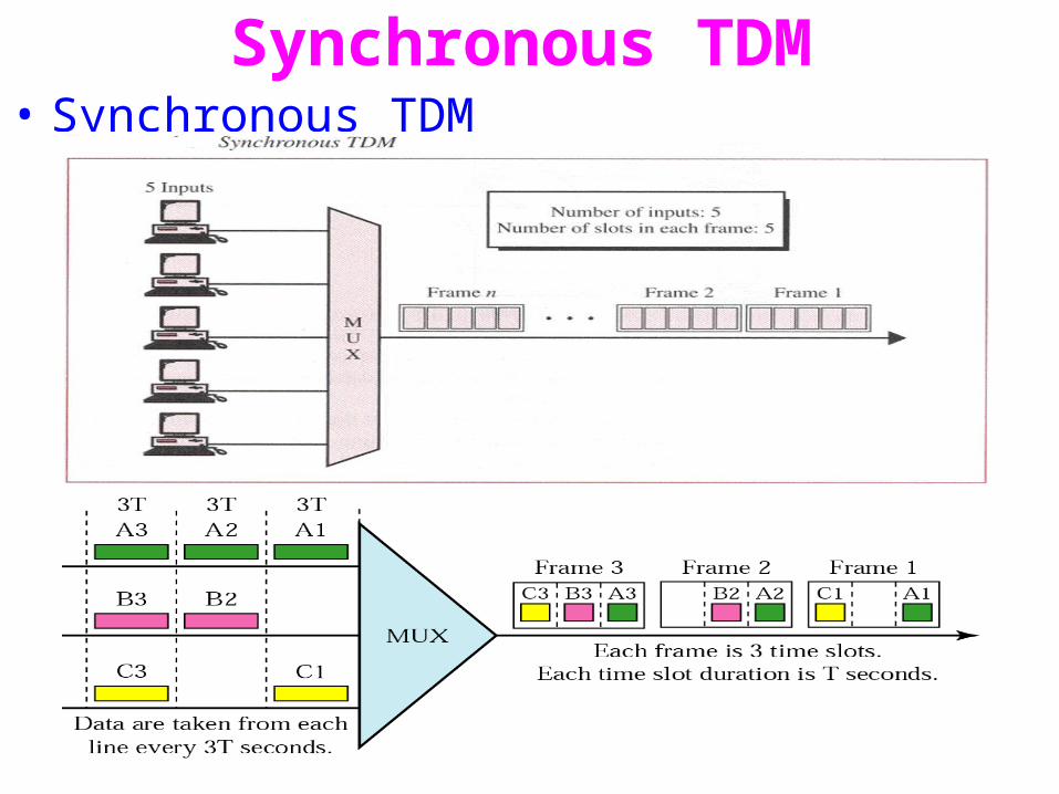
Synchronous TDM• Synchronous TDM
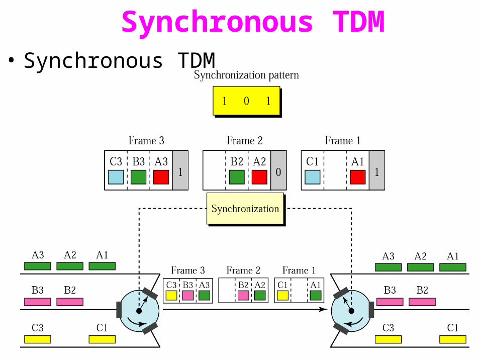
Synchronous TDM• Synchronous TDM
Asynchronous TDM• Synchronous TDM does not guarantee that the full
capacity of a link is used.
• Because the time slots are preassigned and fixed, whenever a connected device is not transmitting, the corresponding slot is empty.
• Asynchronous TDM is designed to avoid this type of waste.
• Asynchronous TDM is efficient only when the size of the time slots kept relatively large

Asynchronous TDM• In asynchronous TDM the total speed of the input lines can be
greater than the capacity of the link.
• The number of time slots in an asynchronous TDM frame (m) is based on statistical analysis of the number of input lines that are likely to be transmitting at any given time.
• With n input lines, the frame contains no more than m slots, with m less than n.
• • In asynchronous TDM each time slot must carry an address telling
the demultiplexer how direct the data.

Asynchronous TDM
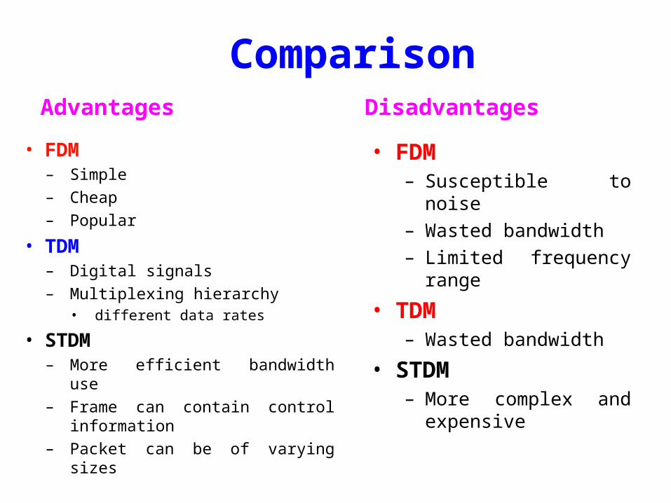
ComparisonAdvantages Disadvantages
• FDM– Simple– Cheap – Popular
• TDM– Digital signals – Multiplexing hierarchy
• different data rates
• STDM– More efficient bandwidth use – Frame can contain control
information– Packet can be of varying sizes
• FDM– Susceptible to noise– Wasted bandwidth– Limited frequency range
• TDM– Wasted bandwidth
• STDM– More complex and
expensive

Telemetry• Defined as measurement at a distance.• Collect the data from several measurement points
at inaccessible, inconvenient locations ,transmit that data to convenient locations and present it in usable form
• Parts of telemetry system 1) Transmitter 2) Receiver 3) Channel
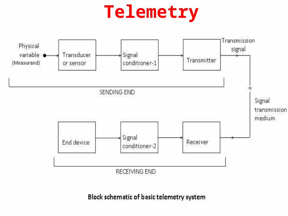
Telemetry
Telemetry• The function of the telemeter transmitter is to convert output of a
primary sensing element into an electrical signal and to transmit it over a telemetering channel.
• This signal is received by a receiver at remote location and convert it to the usable form and is recorded by an end device.
• Types of telemetry system
1.Land Line telemetry
2.Radio Frequency telemetry system
Telemetry• Landline Telemetry • Direct transmission of information through cables and transmission
lines. • Direct transmission via cables employs current, voltage, position,
frequency, or impulses to convey information.• Curent, voltyage and position type are used for short distance
whereas frequency, pulse systems are used for long distance. • Information may be analog / digital . Pulse signals can be used in
digital telemetry . All the others are used for analogtelemetry• Classified into 1.Voltage telemetring sytems 2.Current telemetring sytems
3.Position telemetring sytems
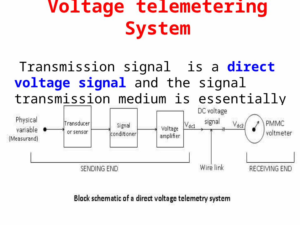
Voltage telemetering System
Transmission signal is a direct voltage signal and the signal transmission medium is essentially a copper wire line.
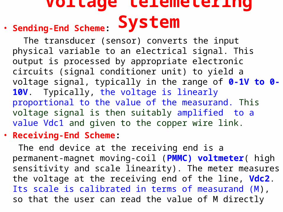
Voltage telemetering System• Sending-End Scheme: The transducer (sensor) converts the input physical variable to an
electrical signal. This output is processed by appropriate electronic circuits (signal conditioner unit) to yield a voltage signal, typically in the range of 0-1V to 0-10V. Typically, the voltage is linearly proportional to the value of the measurand. This voltage signal is then suitably amplified to a value Vdc1 and given to the copper wire link.
• Receiving-End Scheme: The end device at the receiving end is a permanent-magnet moving-
coil (PMMC) voltmeter( high sensitivity and scale linearity). The meter measures the voltage at the receiving end of the line, Vdc2. Its scale is calibrated in terms of measurand (M), so that the user can read the value of M directly

Voltage telemetering System• Transmission Error:The voltage at the receiving end is given by Vdc2 = Vdc1 – I Rwhere I is the line current and R is the resistance of the line• Demerits1. It can be used only for short distances as both the error
and the cost of line increase with the length of the wire line.
2. As the line current is small, the leakage currents could become comparable and thereby cause a large error in the meter reading.
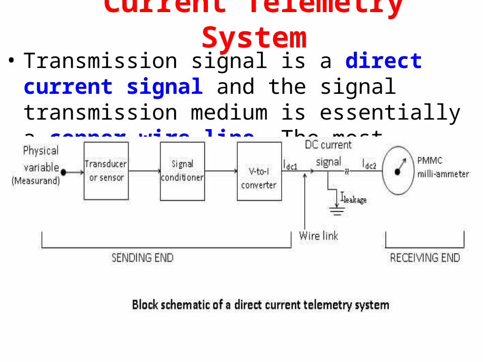
Current Telemetry System• Transmission signal is a direct current signal and
the signal transmission medium is essentially a copper wire line. The most commonly used current signal is 4-20mA
Current Telemetry System• Sending-End Scheme: Very similar the direct voltage telemetry scheme.
The difference in the sending-end schemes is that the direct current system employs a voltage to current converter while the direct voltage system uses a voltage amplifier
• Receiving-End Scheme: The end device is a PMMC milli-ammeter as it has
to read the value of the line current at the receiving end, Idc2, which is in milli-ampere range. Its scale is calibrated in terms of the measurand (M)
Current Telemetry System• Transmission Error: The line current at the receiving end is given by Idc2 = Idc1
– Ileakage where Idc1 is the line current at the sending end and Ileakage is the small current leaking from one wire of the line to the other wire or to the ground due to a finite value of insulation resistance
• Disadvantages: The only demerit or limitation of this telemetry system is
that it can be used only for short distances because the error due to
leakage can become substantial if the length of the wire line is large, and the cost of the line increases directly with its length
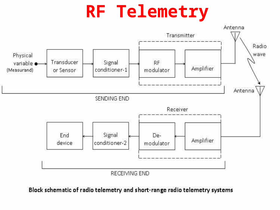
RF Telemetry
• The signal transmission medium is a radio link comprising a transmitting antenna , receiving antenna and the space.
• The transmitter comprises a RF modulator between the two used for propagation of radio wave from TA to RA. The transmitter comprises a RF modulator and an amplifier. The receiver comprises an amplifier and a demodulator.
Mainly divided into
• Short-Range Radio Telemetry System
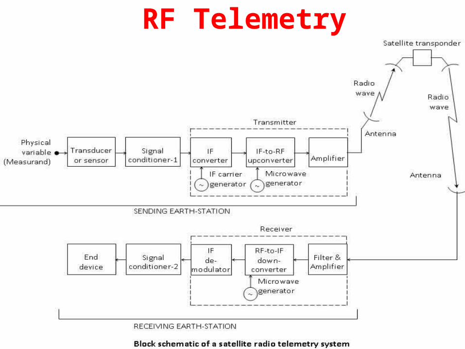
• Satellite Radio Telemetry System
RF Telemetry
RF Telemetry
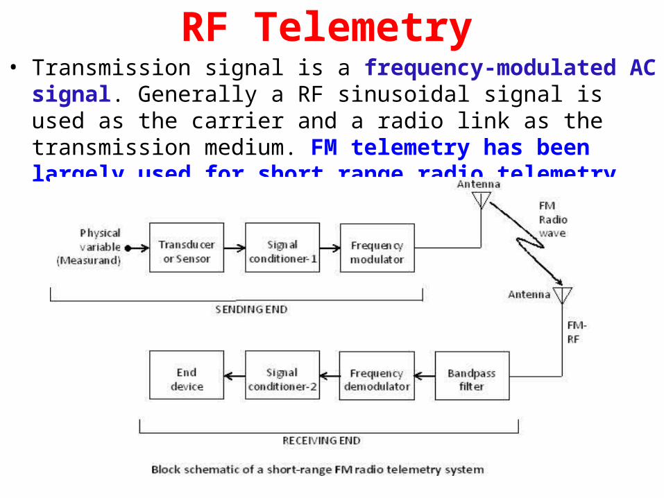
RF Telemetry• Transmission signal is a frequency-modulated AC signal. Generally a
RF sinusoidal signal is used as the carrier and a radio link as the transmission medium. FM telemetry has been largely used for short range radio telemetry

RF Telemetry• Sending-End Scheme: A transducer converts the given physical variable into an electrical
output, which is conditioned/ processed by an appropriate signal conditioner to yield a dc voltage proportional to the value of the measurand, M. This voltage signal is used for the frequency modulation of a radio-frequency (RF) carrier. The frequency-modulated radio-frequency (FM-RF) signal is applied to a transmitting antenna
Receiving-End Scheme The receiver selects the desired signal by employing a band-pass filter. This signal is demodulated using a frequency demodulator thereby recovering the information signal. Signal conditioner processes the
information signal to make it compatible to the given end device
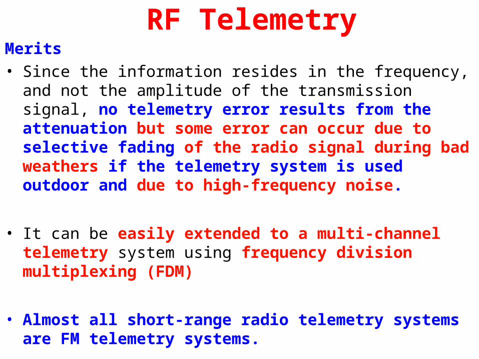
RF TelemetryMerits• Since the information resides in the frequency, and not the
amplitude of the transmission signal, no telemetry error results from the attenuation but some error can occur due to selective fading of the radio signal during bad weathers if the telemetry system is used outdoor and due to high-frequency noise.
• It can be easily extended to a multi-channel telemetry system using frequency division multiplexing (FDM)
• Almost all short-range radio telemetry systems are FM telemetry systems.

Pulse Telemetry• Commonly used in long distance telemetry
• Classified into
1.Analog(PAM,PWM) telemetry
2.Digital( PCM) Telemetry
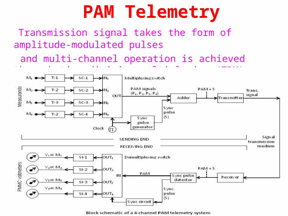
PAM Telemetry Transmission signal takes the form of amplitude-modulated pulses and multi-channel operation is achieved through time-division
multiplexing (TDM).
PAM Telemetry• Sending-End Scheme A 4-channel PAM telemetry system is shown. Measurands, M1 to M4,
are applied to appropriate transducers, T1 to T4, respectively. The transducer outputs are processed in suitable signal conditioners, SC-1 to SC-4 and produces dc voltages V1 to V4, proportional to M1 to M4, respectively. These voltage signals are applied to a 4-channel multiplexing switch at its input terminals, IN1 to IN4. The multiplexing switch functions under the control of a clock in a cyclic order. The output is thus a time-multiplexed PAM signal. Synchronization between transmitter and receiver s achieved by adding sync pulse to PAM signals before transmitting them to the receiving end.
PAM Telemetry• Receiving-End Scheme The receiver gets the sync pulse as well as PAM signals. The
sync pulse is identified by a sync pulse detector (on the basis of amplitude) and delivered to the synchronization circuit. The time-multiplexed PAM signal is applied to the de-multiplexing switch, which outputs the pulses P1 to P4 at its output terminals, OUT1 to OUT4, respectively. These pulsed signals are interpolated by the signal interpolators, SI-1 to SI-4 thereby producing continuous voltage signals, V1 to V4, proportional to P1 to P4, respectively. Finally, these voltages are read on respective PMMC voltmeters, which are calibrated in terms of values of the measurands, M1 to M4.
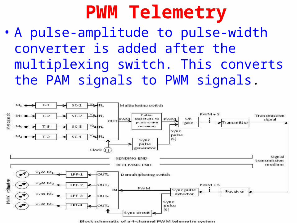
PWM Telemetry• A pulse-amplitude to pulse-width converter is
added after the multiplexing switch. This converts the PAM signals to PWM signals.
• The information resides in the width and not in the amplitude of the pulses, theoretically no telemetry error can result from the attenuation during transmission. PWM telemetry system is cheaper.Commonly used
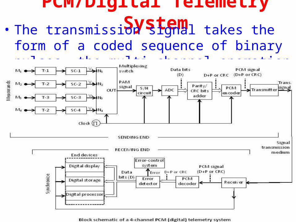
PCM/Digital Telemetry System• The transmission signal takes the form of a coded
sequence of binary pulses ,the multi-channel operation is achieved through time-division multiplexing (TDM)
PCM/Digital Telemetry System• Sending-End Scheme A 4-channel PCM telemetry system is shown. A sample-and-hold
circuit is placed before the ADC to sample the PAM signal and hold the sample at a constant value. The sampled value of the analog signal is converted to its equivalent digital value by an ADC. The data transmission can be either asynchronous or synchronous. In case of asynchronous transmission, this circuit adds a parity bit to each character, that is, n-bit data output of the ADC. In case of synchronous transmission, the circuit adds a certain number of cyclic-redundancy-check bits (CRC bits) at the end of the complete data block. PCM Encoder encodes the augmented data into series of coded pulses using a certain PCM code. In case of asynchronous transmission, trasmitter adds start and stop pulses before and after each data character. In case of synchronous transmission, it adds a synchronization bit pattern before the entire data block and converts the coded voltage pulses into a transmission signal to suit the given transmission medium and the desired range of transmission.
PCM/Digital Telemetry System• Receiving-End Scheme The receiver synchronizes with the transmitter by using either the
start and stop pulses or the synchronization bit pattern. It extracts the PCM signal from the signal received from the sending end. A PCM decoder decodes the serial coded pulses back into augmented data (comprising data bits and parity/CRC bits). This data is passed onto an error detector, which verifies the correctness of the data either from the parity bits or from the CRC bits. In case an error is detected, the information is passed on to the error control system for suitable action. If no error has been detected, then the data bits alone are passed onto the end devices.
• Merits
The digital telemetry system has high immunity to noise. Since the digital telemetry uses error control techniques as a standard feature
thereby ensuring that the data reaching the end devices is error free.