Unit 18 Trusses: Method of Joints - Secrets of · PDF fileUnit 18 Trusses: Method of Joints...
37
Introduction to Statics .PDF Edition – Version 0.95 Unit 18 Trusses: Method of Joints Helen Margaret Lester Plants Late Professor Emerita Wallace Starr Venable Emeritus Associate Professor West Virginia University, Morgantown, West Virginia © Copyright 2010 by Wallace Venable Conditions of Use This book, and related support materials, may be downloaded without charge for personal use from www.SecretsOfEngineering.net You may print one copy of this document for personal use. You may install a copy of this material on a computer or other electronic reader for personal use. Redistribution in any form is expressly prohibited.
-
Upload
nguyendiep -
Category
Documents
-
view
242 -
download
2
Transcript of Unit 18 Trusses: Method of Joints - Secrets of · PDF fileUnit 18 Trusses: Method of Joints...

Introduction to Statics.PDF Edition – Version 0.95
Unit 18Trusses: Method of Joints
Helen Margaret Lester PlantsLate Professor Emerita
Wallace Starr VenableEmeritus Associate Professor
West Virginia University, Morgantown, West Virginia
© Copyright 2010 by Wallace Venable
Conditions of UseThis book, and related support materials, may be downloaded
without charge for personal use fromwww.SecretsOfEngineering.net
You may print one copy of this document for personal use. You may install a copy of this material on a computer or other
electronic reader for personal use.Redistribution in any form is expressly prohibited.

Unit 18Trusses: Method of Joints
Frame 18-1
*Introduction
A truss is a structure composed of several members joined at their ends so as to form a rigid body. They are used to span greater distances and to carry larger loads than can be done effectively by a single beam or column. Consequently they are of great importance to the engineer who is concerned with structures. They are commonly used to form bridges and to support roofs. Variations on the truss form are also used in large machines.
Go to the next frame.
*This topic is sometimes excluded from a short statics course. Check your schedule to see if your instructor requires you to study it at this time.

Correct response to preceding frame
No response
Frame 18-2
Typical Trusses
Trusses are composed of reasonably slender load-carrying members connected to one another by pin joints, which are at the ends of the members.
In the drawings shown, the line segments represent ________________________ and
the circles represent ___________________________________ .

Correct response to preceding frame
memberspin joints
Frame 18-3
Assumptions
In the initial analysis of trusses three assumptions are made. These assumptions are usually more or less false but are necessary to allow one to get started. In actual design work it may be necessary to correct for the original assumptions in later stages.
The assumptions are:1. The members are joined by smooth pins at their ends.2. Loads and reactions act only at the joints.3. The weights of the members are negligible.
Which of these assumptions would you think was most likely to be true?
______________________________________________________________________

Correct response to preceding frame
Assumption 2 is most nearly correct since it is usually possible to use crossbeams in such a way that loads do come on only at the joints.
Assumption 1 is usually wrong since pin connections are seldom used now. Riveted and welded joints are more common.
Assumption 3 is usually wrong, of course, since truss members are quite hefty. Some allowance is made by increasing the calculated loads to include this weight.
Frame 18-4
Recognition
Which of the frames shown would not be classified as a truss? Why?
$ Not a truss because
________________________________________
$ Not a truss because
________________________________________
$ Not a truss because
________________________________________

Correct response to preceding frame
Frame (b) cannot be treated as a truss because the load is not applied at a joint.Frame (c) cannot be treated as a truss since to resist the load at E, CDE must be a single member and is therefore not joined at its end alone.
Frame 18-5
Line of Action
Since loads may only come on a truss at its joints, any member of a truss is loaded
only at its __________________ .
All joints in trusses are assumed to be _________________ connections.
Therefore every member of a truss has a __________________ at each end.

Correct response to preceding frame
ends, joints, (Or equivalent response) pinpin, pin joint (Or equivalent response)
Frame 18-6
Line of Action
The free body below represents a typical truss member and the forces acting on it.
On the second sketch, replace the system shown by two forces, one at each pin. Check to make sure the member is in equilibrium.

Correct response to preceding frame
In order for the member to be in equilibrium |F 1| = |F 2| and both must act along the line of the member.
Frame 18-7
Line of action
Since trusses are loaded only at the joints, they are made up entirely of two-force
members. Thus, the force exerted by each end pin on any member is _____________the member.

Correct response to preceding frame
along, parallel to
Frame 18-8
Line of Action
1. What is the line of action of the force in member EJ ? _______________________
2. In member DI ? ___________________
3. Draw on the truss the line of action of the force in member CD .

Correct response to preceding frame
1. horizontal2. vertical
Frame 18-9
Transition
Trusses are rigid bodies made up of a number of members fastened at their ends. In their analysis simplifying assumptions are made so that they are considered to be pin connected and loaded at the pins only. This results in a series of two force members, so that the line of action of the force on any member in a truss is along the member and therefore is apparent by inspection.
The next section will show you how to use this fact to find the forces in the members.
Go to the next frame.

Correct response to preceding frame
No response
Frame 18-10
Free Body Diagrams
In working with trusses you do one new thing. You draw a free body of a part of a member and show the forces acting on that part. It is very little different from what you have been doing.

FBD (a) shows the forces acting on a member of a truss. Complete FBD (b) which shows the lower part of the same member.

Correct response to preceding frame
Frame 18-11
Free Body Diagrams
Here is a free body showing the directions of forces in part of the members that come together at E. Complete it. (No magnitudes, of course.)
Now complete joint D.

Correct response to preceding frame
Frame 18-12
Free Body Diagrams
Often the free body diagram is simplified to show only the forces and the joint and not the sections of the members. For example:

Represent the joint B with the simplified FBD.

Correct response to preceding frame
Frame 18-13
Forces in Members
Rather than giving the forces in a truss member signs corresponding to a vector notation, it is customary to classify them as tension or compression. If, in the free body of the joint, the force points away from the joint, it represents a pull or tension. A force pointing toward the joint is a compressive force.
In the joint shown, which members are in tension?
________________________________
Which members are in compression?
________________________________

Correct response to preceding frame
Members AD, CD and DE are in tensionMember BD is in compression
Frame 18-14
Forces in Members
Members AB, BD, DF and DE are in compression. Members AC, CE, BC and BE are in tension.
Complete the free body of joint A. Then draw a free body of joint B. (still no magnitudes)
Correct response to preceding frame
Note that while member AB is shown as compression in both free bodies, the directions of the forces are opposite.
Frame 18-15
Forces in Members
When you have drawn a correct free body of a joint, magnitudes of forces can be found, provided that no more than two forces are unknown. As you have probably suspected, this is done by writing #F = 0For joint A

Correct response to preceding frame
AC = 3000 N tension
Frame 18-16
Forces in Members
On a truss problem, it is often helpful to write in values as you solve for them. I have done so above.
With AB and AC known, let's look at joint B. Sense of unknown forces is assumed. (You may either make a guess based on intuition, or a perfectly arbitrary assumption.)
From the free body above, can you solve for the unknown forces?$ Yes $ No
If yes, solve. If no, state why not.

Correct response to preceding frame
No. #F = 0 will provide two equations. There are three unknowns.
Frame 18-17
Forces in Members
Don't give up yet. Try joint C. Remember you know AC = 3000 N tension. Draw your free body and solve, if possible. Use T to indicate tension, C to indicate compression.

Correct response to preceding frame
BC = 1000 N T CE = 3000 N T
Frame 18-18
Forces in Members
So far you know AB = 5000 N C AC = 3000 N T CE = 3000 N T BC = 1000 N T
With BC known, you can now solve joint B. Do so.

Correct response to preceding frame
Frame 18-19
Forces in Members
Now look at joints D and E. Which one can be solved now? ____ Solve it.
Now can you solve the other one? $ Yes $ No
Do you want to? $ Yes $ No

Correct response to preceding frame Joint D.
Yes. Joint E can now be solved.No, I don't. (My response. Yours may be different. If so, go right ahead.)
Frame 18-20
Transition
As you can see, you can go on until you reach either the end of the truss or the end of your patience.
For some obscure reason, this is called the method of joints. Its principal merit lies in finding the forces in members near the ends of trusses and in examining special joints.
We've done the former. Now let's do the latter.
Go to the next frame.

Correct response to preceding frame
No response
Frame 18-21
Special Joints
The first special case you have seen already. Complete the FBDs and write down the unknowns.
AB = _________BC = _________
CD = _________DE = _________
EF = _________FG = _________

Correct response to preceding frame
AB = 2000 N T BC = 4000 N TCD = 873 lb T DE = 500 lb C EF = N TFG = M T
Frame 18-22
Special Joints
When a joint is acted upon by forces whose lines of action form two intersecting
straight lines, opposite forces must be __________________ .

Correct response to preceding frame
equal
Frame 18-23
Special Joints
Now look at these special joints and solve for the unknown forces. (In your head, if you wish.)
AB = __________BC = __________
CD = __________DE = __________

Correct response to preceding frame
AB = 0BC = 368 N CCD = 0DE = 500 lb T
Frame 18-24
Special Joints
When a joint connects three members, two of which form a straight line, the forces in
the two collinear members are _________________ , and the force in the third member
is __________________ .

Correct response to preceding frame
equal zero
Frame 18-25
Special Joints
In the truss shown below, write 0 on any member that carries zero force (as I have done on Hh) and write the magnitude and kind of force (for example, 300 T) along any member you can solve by inspection.

Correct response to preceding frame
Frame 18-26
Zero Members
The picture below shows the truss from the preceding frame with the zero members omitted. Look at it again and write 0 on any member that you can now identify as a zero member.

Correct response to preceding frame
Frame 18-27
Zero Members
The truss is shown again with the zero members omitted. Find any additional zero members.

Correct response to preceding frame
Gg is a zero member.There are no more zero members in this truss with this loading.
Frame 18-28
Special Joints
Identify and label all the zero members in the truss shown below. Use the approach you used on the preceding frames.

Correct response to preceding frame
Frame 18-29
Review
Some students are bothered by the idea that a structure might be built with zero force members which "carry no load." As far as completing statics goes, we can ignore the issue. Often they are included to carry loads which move to another location, as with cars crossing a bridge, and which require another whole set of solutions. They are also used a bracing to prevent buckling, a topic you will study in "strength of materials."
Complete pages 18-1 and 18-2 in your notebook.

Correct response to preceding frame
No response
Frame 18-30
Transition
As the last frames show, it's a dandy idea to take time to identify special joints before you start a more elaborate solution. It can save a lot of time.
Now all that is left is to put together all these bits of information and solve a couple of problems.
Go to the next frame.

Correct response to preceding frame
No response
Frame 18-31
Truss Analysis
Find the reactions at E and A.
Put them on your sketch.
Examine for special joints and write any information they give you.
Correct response to preceding frame
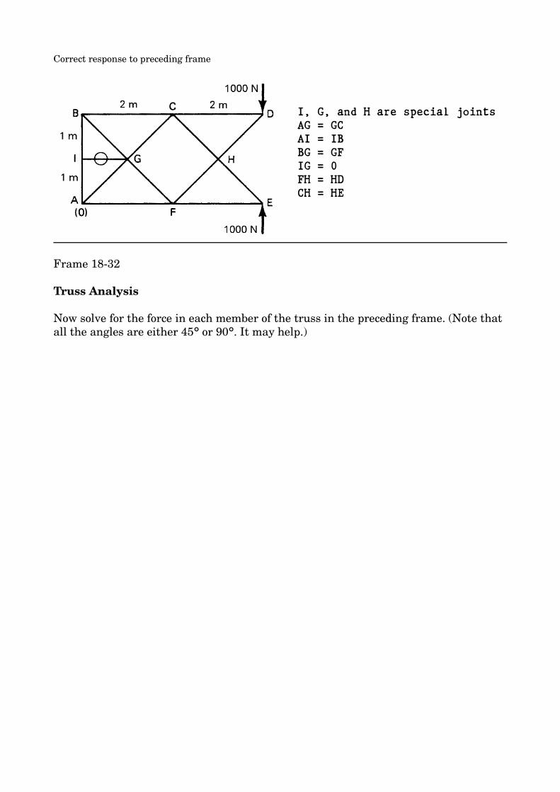
I, G, and H are special jointsAG = GCAI = IBBG = GFIG = 0FH = HDCH = HE
Frame 18-32
Truss Analysis
Now solve for the force in each member of the truss in the preceding frame. (Note that all the angles are either 45 or 90 . It may help.)° °
Correct response to preceding frame
From Joint E HE = CH = 1414 N CFE = 1000 N T
From Joint D DH = HF = 1414 N CCD = 1000 N T
From Joint CCG = AG = 1414 N TCB = 1000 N C
From Joint F FG = GB = 1414 N TAF = 1000 N C
From Joint A AB = 1000 N C
Frame 18-33
Truss Analysis
Do the Problem 18-1 on page 18-3 of your notebook.
Then go to the next frame.

Correct response to preceding frame
Frame 18-34
Conclusion
This unit has been devoted to the analysis of trusses by the "method of joints." It is often tedious, as you have seen, however it can also give quite elegant results by reducing the complexity of the problem at hand. It is frequently used for this purpose, even when used with a solution by the "method of sections."
As you undoubtedly just realized the next unit will deal with the "method of sections."