Unit-1 INTRODUCTIONsrmooad.weebly.com/uploads/4/5/1/2/45121557/unit-1.pdf · INTRODUCTION :...
25
1 Unit - 1 INTRODUCTION SYLLABUS: Categories of Information systems-traditional paradigm vs. Object oriented paradigm-Objects and Classes-Inheritance-Object relationship-Examples of UML class modeling-Unified Process- Iteration and incrementation within the unified process. INTRODUCTION : Object-oriented analysis and design (OOAD) is a software engineering approach that models a system as a group of interacting objects. Each object represents some entity of interest in the system being modeled, and is characterized by its class, its state (data elements) and its behavior. Various models can be created to show the static structure, dynamic behavior, and run-time deployment of these collaborating objects. There are a number of different notations for representing these models, such as the Unified Modeling Language (UML). Benefits Easy to understand Maintainability Data re-use 1.1 CATEGORIES OF INFORMATION SYSTEMS A system is a set of artifacts (components) that together achieve some outcome. An information system is a system that achieves a business outcome. It collects, manipulates, stores and reports information regarding the business activities of an organization in managing the operations of the business. The two major categories of computerized Information systems are Custom information Systems Commercial off-the-shelf (COTS) packages
Transcript of Unit-1 INTRODUCTIONsrmooad.weebly.com/uploads/4/5/1/2/45121557/unit-1.pdf · INTRODUCTION :...

1
Unit-1
INTRODUCTION SYLLABUS: Categories of Information systems-traditional paradigm vs. Object oriented paradigm-Objects and
Classes-Inheritance-Object relationship-Examples of UML class modeling-Unified Process-
Iteration and incrementation within the unified process. INTRODUCTION :
Object-oriented analysis and design (OOAD) is a software engineering approach that
models a system as a group of interacting objects. Each object represents some entity of
interest in the system being modeled, and is characterized by its class, its state (data elements)
and its behavior. Various models can be created to show the static structure, dynamic behavior,
and run-time deployment of these collaborating objects. There are a number of different notations
for representing these models, such as the Unified Modeling Language (UML).
Benefits
Easy to understand Maintainability Data re-use
1.1 CATEGORIES OF INFORMATION SYSTEMS
A system is a set of artifacts (components) that together achieve some outcome. An
information system is a system that achieves a business outcome. It collects, manipulates, stores
and reports information regarding the business activities of an organization in managing the
operations of the business.
The two major categories of computerized Information systems are
Custom information Systems
Commercial off-the-shelf (COTS) packages

2
Custom Information System (CIS) is an information system that has been developed for one
specific client. For example, the information system developed for Jethro’s Boot Emporium is a
custom Information System- the boot fashion trend detection component is used by no other
company. The 3 main stakeholders when a Custom Information System is developed are
The Client, who is paying for the Information System to be developed The future Users of the Information system. The developers of that information system
The task of the developers is to determine the needs of the client and to develop an information
system that satisfies those needs and can effectively be utilized by the users. Another example of
a custom information system is a management information system for a major car rental
company.
Disadvantage: Custom Information Systems are expensive and an organization might be
tempted to recoup some of the cost by selling a copy of its custom information system to its
competitor. For this reason, the resale market for this system is small. CIS incorporates the
business model of organization that commissioned it and selling a copy of such a CIS means
giving away proprietary information to a competitor.
Commercial-Off-The-Shelf (COTS) is also called Shrinkware, because the diskettes or CDs on
which the package used to be supplied were placed in a box together with the manual and the
box was then shrink-wrapped. Nowadays, however, COTS packages are frequently downloaded
over the Internet- called as Clickware. There are only two major stakeholders for a COTS
package:
The Developers
The Users COTS packages are intended to provide functionality that will satisfy the needs of as large a user
base as possible. Some COTS are relatively small and cheap and are intended to satisfy the
information system needs of smaller businesses. COTS packages include TurboTax, Microsoft
Excel and Peachtree Accounting System.
3
In contrast, an Enterprise Resource Planning (ERP) system such as PeopleSoft or SAP is a huge
package intended to provide almost all the information needs of a large corporation,
including accounting, payroll, inventory, sales, purchasing and personnel and so on. Thus COTS
packages like ERP systems lie between the pure CIS and COTS packages that are unchangeable.
1.2 TRADITIONAL INFORMATION SYSTEM DEVELOPMENT
The information system life cycle is the way that an information system is constructed, as it is
almost always easier to perform a sequence of smaller tasks than one large task, the overall life
cycle is broken into a series of smaller steps called phases. The number of phases varies from
organization to organization. Typically there are six phases Requirements phase
In this phase, the client’s requirements are extracted. The client and the future users of
the information system to be developed interact with the information system development team
in order to determine the client’s needs. The results of this study are presented in the form of a
requirements document. The requirements document is only a few pages long, with the specific
needs listed as bullet items. Analysis Phase
The aim is to draw up the specification document. The specification document lays out
what the information system has to do. If the delivered information system satisfies the
specifications, then the client pays the developers for the information system. If not the
developers have to fix the information system until it satisfies the specifications. The
specifications describe what the system has to be able to do. Once the specification document has
been signed off by the client, the project management plan can be drawn. This detailed plan
includes a budget, staffing needs and a list of what will be delivered to the client and when it will
be delivered. Design Phase
In this the members of the development team describe how the information system is
developed. Typically the system is broken into smaller pieces called modules.

4
Each module is designed in detail; the development team has to describe the algorithms
used by the module (how the module performs the task) and data structures within the modules
(data on which the module is to operate). The result is represented in the form of a design
document.
Implementation phase
The design of the modules is given to the design team to translate into an appropriate
programming language. COBOL is the world’s most widely used programming language,
whereas the modern information systems are often implemented in C++ or Java. Modules are
integrated (combined) to form the complete information system.
Maintenance phase
After the information system has been installed, it will need to be modified either to
remove any remaining faults from the system or because the system needs to be extended in
some way. Retirement
Finally after 10 or 15 years of maintenance, an information system is retired if it is no
longer performs a useful service.
There is no planning phase
o Beginning of the project-preliminary planning takes place to manage the requirements
and analysis phases
o To draw management plan-budget, staffing requirements and detailed schedule
o Project management need to monitor the project management plan and be on the watch
for any derivation from the plan. There is no planning phase instead; planning activities are carried out all through the life cycle.
There is no testing phase
o Validation and verification is missing

5
There is no documentation
o It is necessary to update each information of the system development. It is necessary when
the developer changes, as the document designing will be tedious.
o Essential for back reference in case of troubleshooting.
o Necessary for testing a new client’s requirement.
o Maintenance is impossible if there is no documentation 1.3 Traditional Paradigm Vs Object-Oriented Paradigm
The computer age started in the 1940s, so Information Systems (IS) are hardly more than
50 years old. Developing IS was initially considered a creative skill; individuality was highly
prized. However, as larger computers became more affordable, it became possible to run an
information system that was too big to be developed by just one person, if that information
system was to be completed by the deadline specified by the client. Instead, IS began to be
developed by teams. Furthermore skill specialization became the industry norm. Instead of
information technology professionals being involved in all the phases- 2 separate professions
arose: System analysts to perform the requirements, analysis and design phases and
Programmers to do the implementation.
The first systematic approach to information is called the Traditional paradigm
/methodology or Structured methodology /paradigm. Initially this method was extremely
successful. This was treated as methodical discipline rather than a creative activity. The quality
of Information system improved and the delivery of the IS on time and within the budget started
to become a realistic expectation.
During the 1980s, the cost of hardware continued to decrease fast. As larger computers
became more affordable, the size of IS continued to grow. But larger the IS, the less successful
the traditional paradigm proved to be. Finally, the IS community realized that the traditional
paradigm had outlined its usefulness and something more was needed.

6
Traditional method went well with small scale IS (approx. 5000 lines of code), but not
with medium scale IS (approx. 50000 lines of code) and long scale IS (approx. 5000000 lines of
code). This method ignored the data in favor of the operations.
In contrast, the Object-Oriented Paradigm pays equal attention to operations and data.
The Standish Group is a research firm that analyses the development of IS. Their study of
280000 development projects completed in 2000 and is summarized as
The financial and legal implications of unsuccessful projects are horrendous. A survey conducted
by the Cutter Consortium revealed that an astounding 78 percent of the information technology
organizations surveyed have been involved in disputes that ended up in litigation
In 67% of the disputes, the functionality or performance of the information system as
delivered did not meet up to the claims of the developers
In 56% of the disputes, the promised delivery date slipped several times
In 45% of the disputes, the defects were so severe that the information system was
unusable. These reasons forced organizations to change to the object-oriented paradigm.
1.4 OBJECTS & CLASSES
A class is a set of objects that share a common structure (instance variables) and behavior
(methods) and the inheritance for objects. The chief role of a class is to define the
properties and procedures (state and behavior) and applicability of its instances.
7
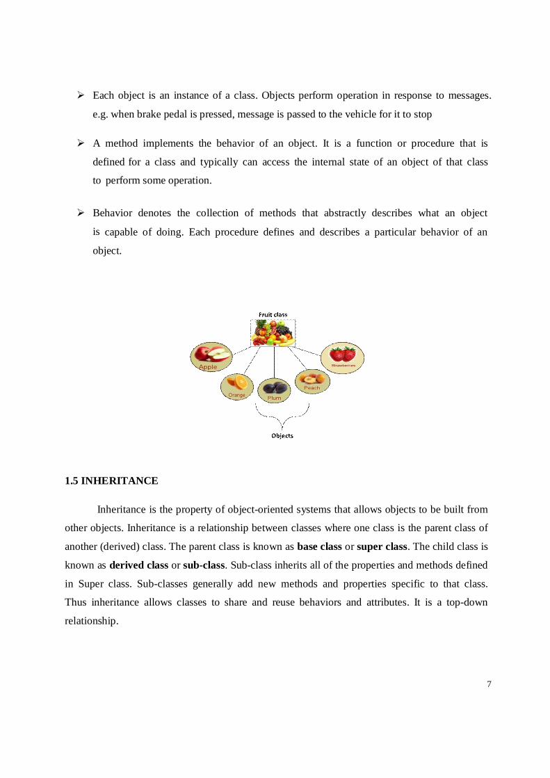
Each object is an instance of a class. Objects perform operation in response to messages.
e.g. when brake pedal is pressed, message is passed to the vehicle for it to stop
A method implements the behavior of an object. It is a function or procedure that is
defined for a class and typically can access the internal state of an object of that class
to perform some operation.
Behavior denotes the collection of methods that abstractly describes what an object
is capable of doing. Each procedure defines and describes a particular behavior of an
object.
1.5 INHERITANCE
Inheritance is the property of object-oriented systems that allows objects to be built from
other objects. Inheritance is a relationship between classes where one class is the parent class of
another (derived) class. The parent class is known as base class or super class. The child class is
known as derived class or sub-class. Sub-class inherits all of the properties and methods defined
in Super class. Sub-classes generally add new methods and properties specific to that class.
Thus inheritance allows classes to share and reuse behaviors and attributes. It is a top-down
relationship.

8
The Bank Account Class is a class and the Current Account Class is a subclass of Bank Account
Class. The open triangle below Bank Account Class tells that Current Account Class has all the
features of Bank Account Class (derived part) but in addition has features of its own that are
specific to Current Account Class (incremental part) such as Calculate interest. The different
ways of describing the relationship are
1) Current Account class is a subclass of Bank Account Class
2) Bank Account Class is a super class of Current Account Class
3) Current Account class is a specialization of Bank Account Class
4) Bank Account Class is a generalization of Current Account Class
5) Current Account class is a Bank Account Class
6) Bank Account Class is the base class; Current Account Class is the derived class
7) Bank Account Class is the parent class; Current Account Class is the child class Therefore Current Account class inherits from Bank Account Class
These ideas can be extended to Savings Account Class as well. Thus both Current Account Class
and Savings Account Class inherit all the features from Bank Account Class along with its own
features.
Types of Inheritance :
1) Single Inheritance: Derivation of class from only one base class is called single inheritance.
2) Multiple Inheritance:Derivation of class from several base class is called multiple
inheritance.

9
3) Hierarchical Inheritance: Derivation of several classes from a single class is
called hierarchical inheritance.
4) Multilevel Inheritance: Derivation of a class from another derived class is called multiple
inheritance.
5) Hybrid Inheritance: Derivation of a class involving more than one form of inheritance
is called hybrid inheritance.
1.6 OBJECT RELATIONSHIPS
GENERALIZATION
Generalization is a mechanism for combining similar classes of objects into a single
general class. It identifies commonalities among a set of entities. The commonality may be
attributes, behavior or both. Inheritance can be equalized to inheritance. Inheritance is
programming implementation of generalization. Generalization is a bottom-up process.
SPECIALIZATION
It is an ability of an object to inherit operations and attributes from the super class or base
class with possible restrictions and additions.
Figure : Generalization & Specialization
AGGREGATION
Aggregation represents a relation “contains”, “is a part of” and “whole- part” relation. It is
indicated by a line adorned on the “whole” by a hollow diamond along with name of
relationship and cardinality. Example: a Library contains Books (one-to-many)

10
Figure: Aggregation
ASSOCIATION
An association is a connection between classes, a semantic connection between objects of classes
involved in the association. Association typically represents “has a” or “uses” relationships. It is
indicated by a line, sometimes with arrow indicating unidirectional relationship, adorned by the
name of the relation, and the ends of the line adorned by cardinality of relationship and
optionally by the roles connected to each class. It is also known as Client-Server
association or Consumer-Producer association.
Figure : Association POLYMORPHISM
The word “poly‟ means many and “morph‟ meaning form. It is the ability of same operation to
apply to different classes. Basically the ability to define a method in a class and to have
that method exists for all subclasses of that class even when the subclasses a very different in
their behavior. It allows writing generic, reusable code more easily because we can specify
general instruction and delegate the implementation details to the objects evolved.

11
1.7 UNIFIED MODELING LANGUAGE
System is any process or structure. Example: Organizational structure of Corporation-Health
Services, National economy
Model is an abstract representation of a system, constructed to understand the system prior
to building or modifying it. Two types of models are
Static- it is a snapshot of system parameters at specific point of time. E.g. UML diagrams
Dynamic- it is viewed as a collection of procedures or behaviors taken together of a
system over time. The relationships show how the business objects interact to perform tasks.
Modeling
Building a model for a software system prior to its construction is an essential as having a
blueprint for building a large building. Rigorous modeling is essential. It must include
Model elements- which form the fundamental modeling concepts and
semantics.
Notation- visual rendering of model elements
Guidelines- expression of usage within the trade

12
Benefits
Clarity
Familiarity
Maintenance
Simplification Advantages
Models make it easier to express complex ideas
Reduction of complexity by separating the unimportant aspects from those are important
Models enhance and reinforce learning and training
Cost of the modeling analysis is much lower than the cost of similar presentation
conducted with a real system. UML
The unified modeling language (UML) is a language for specifying, constructing, visualizing and
documenting the software system and its components. The UML is a graphical language with
sets of rules and semantics.
The primary goals in the design of the UML are
Provide users a ready-to-use, expressive visual modeling language so they can develop
and exchange meaningful models
Provide extensibility and specialization mechanisms to extend the core concepts.
Be independent of particular programming languages and development processes. Provide
a formal basis for understanding the modeling language.
Encourage the growth of the OO tools market. Support higher-level development concepts.
Integrate best practices and methodologies UML has 9 graphical diagrams
o Class diagram(static) o Use-case diagram(static) o Behavior diagram(dynamic)

13
o Interaction diagram o Sequence diagram o Collaboration diagram
o State chart diagram o Activity diagram o Implementation diagram. o Component diagram o Deployment diagram.
Static Diagrams:
1. CLASS DIAGRAMS
Class diagrams are the backbone of almost every object-oriented method including UML. They
describe the static structure of a system. Classes represent an abstraction of entities with common
characteristics. Associations represent the relationships between classes. Symbols & Notations
Illustrate classes with rectangles divided into compartments. Place the name of the class in the
first partition (centered, bolded, and capitalized), list the attributes in the second partition, and
write operations into the third.
Visibility
Use visibility markers to signify who can access the information contained within a class. Private
visibility hides information from anything outside the class partition. Public visibility allows all
other classes to view the marked information. Protected visibility allows child classes to access
information they inherited from a parent class.

14
Figure:Visibility
Multiplicity (Cardinality)
Place multiplicity notations near the ends of an association. These symbols indicate the number of
instances of one class linked to one instance of the other class. For example, one company will
have one or more employees, but each employee works for one company only.
Figure: Multiplicity
Composition and Aggregation Composition is a special type of aggregation that denotes a strong ownership between Class A,
the whole, and Class B, its part. Illustrate composition with a filled diamond. Use a hollow
diamond to represent a simple aggregation relationship, in which the "whole" class plays a more
important role than the "part" class, but the two classes are not dependent on each other. The
diamond end in both a composition and aggregation relationship points toward the "whole" class
or the aggregate.

15
Figure: Composition and aggregation
2. USE CASE DIAGRAM
Use case diagrams model the functionality of a system using actors and use cases. Use cases are
services or functions provided by the system to its users.
Symbols and Notations System
Draw your system's boundaries using a rectangle that contains use cases. Place actors outside the
system's boundaries.
Use Case Draw the use cases using ovals. Label the ovals with verbs that represent the system's
functions.

16
Actors
Actors are the users of a system. When one system is the actor of another system, label the
actor system with the actor stereotype.
Relationships
Illustrate relationships between actor and a use case with a simple line. For relationships among
use cases, use arrows labeled either "uses" or "extends." A "uses" relationship indicates that
one use case is needed by another in order to perform a task. An "extends” relationship
indicates alternative options under a certain use case.
Figure : Use case Diagram for Bank Information System

17
BEHAVIOR DIAGRAM (DYNAMIC) Interaction Diagrams: The interaction diagrams are divided into
Sequence diagram
Collaboration diagram
3. SEQUENCE DIAGRAMS
Sequence diagrams describe interactions among classes in terms of an exchange of
messages over time. Symbols and Notations
Class roles Class roles describe the way an object will behave in context. Use the UML object symbol to
illustrate class roles, but don't list object attributes.
Activation
Activation boxes represent the time an object needs to complete task.
18
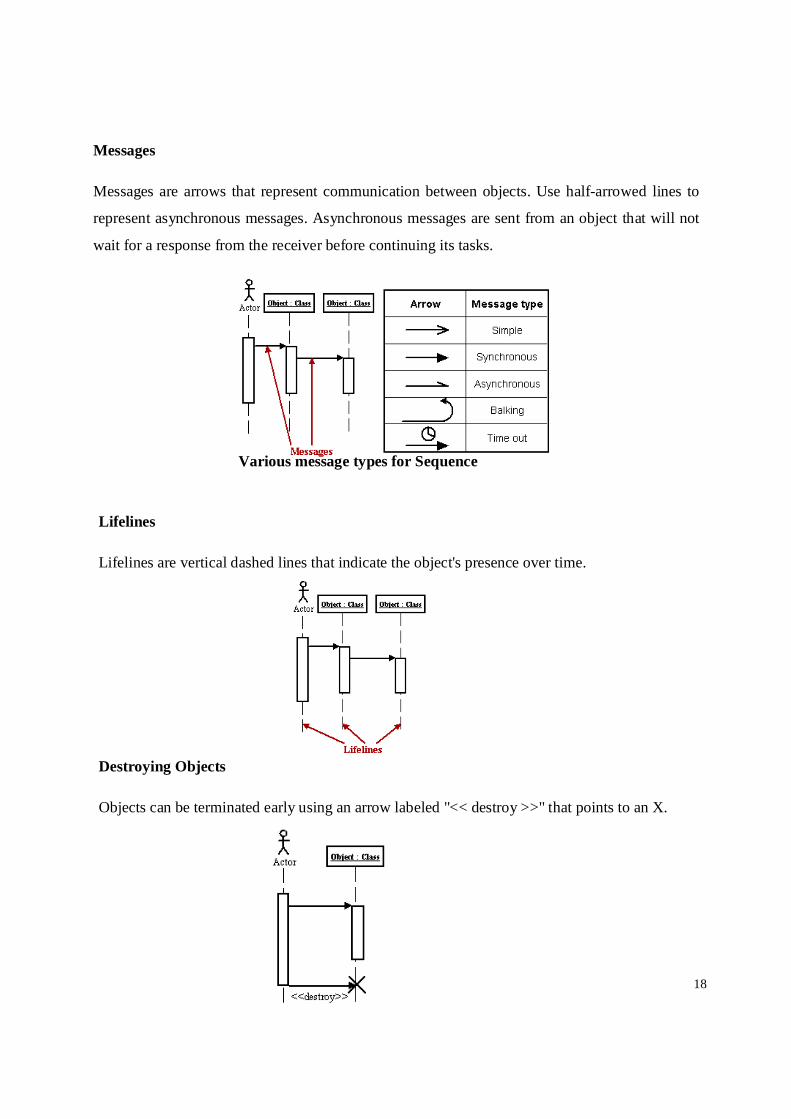
Messages
Messages are arrows that represent communication between objects. Use half-arrowed lines to
represent asynchronous messages. Asynchronous messages are sent from an object that will not
wait for a response from the receiver before continuing its tasks.
Various message types for Sequence
Lifelines
Lifelines are vertical dashed lines that indicate the object's presence over time.
Destroying Objects
Objects can be terminated early using an arrow labeled "<< destroy >>" that points to an X.

19
Loops A repetition or loop within a sequence diagram is depicted as a rectangle. Place the condition for
exiting the loop at the bottom left corner in square brackets [ ]4
4.COLLABORATION DIAGRAM A collaboration diagram describes interactions among objects in terms of sequenced messages.
Collaboration diagrams represent a combination of information taken from class, sequence, and
use case diagrams describing both the static structure and dynamic behavior of a system. Symbols and Notations
Class roles
Class roles describe how objects behave. Use the UML object symbol to illustrate class roles, but
don't list object attributes. Association roles
Association roles describe how an association will behave given a particular situation. Association roles can be drawn using simple lines labeled with stereotypes.

20
Messages
Unlike sequence diagrams, collaboration diagrams do not have an
explicit way to denote time and instead number messages in order of
execution. Sequence numbering can become nested using the Dewey
decimal system. For example, nested messages under the first message
are labeled 1.1, 1.2, 1.3, and so on. A condition for a message is usually placed in square
brackets immediately following the sequence number. Use a * after the sequence number to
indicate a loop.
5. ACTIVITY DIAGRAM
An activity diagram illustrates the dynamic nature of a system by modeling the flow of
control from activity to activity. An activity represents an operation on some class in the
system that results in a change in the state of the system. Typically, activity diagrams are
used to model workflow or business processes and internal operation. Because an activity
diagram is a special kind of state-chart diagram, it uses some of the same modeling
conventions. Symbols and Notations Action states
Action states represent the non-interruptible actions of objects.
Action Flow Action flow arrows illustrate the relationships among action states.

21
.
Object Flow
Object flow refers to the creation and modification of objects by activities. An object flow
arrow from an action to an object means that the action creates or influences the object. An
object flow arrow from an object to an action indicates that the action state
uses the object.
Initial State
A filled circle followed by an arrow represents the initial action state.
Final State
An arrow pointing to a filled circle nested inside another
circle represents the final action state.
Decision
A diamond represents a decision with alternate paths. The outgoing alternates should be
labeled with a condition or guard expression. You can also label one of the paths "else."

22
Synchronization
A synchronization bar helps illustrate parallel transitions. Synchronization is also called
forking and joining.
Implementation diagrams:
Implementation diagrams can be divided into
o Component diagram
o Deployment diagram 6. COLLABORATION DIAGRAMS
Component diagram describes the organization of the physical components in a system. Symbols and Notations
Component
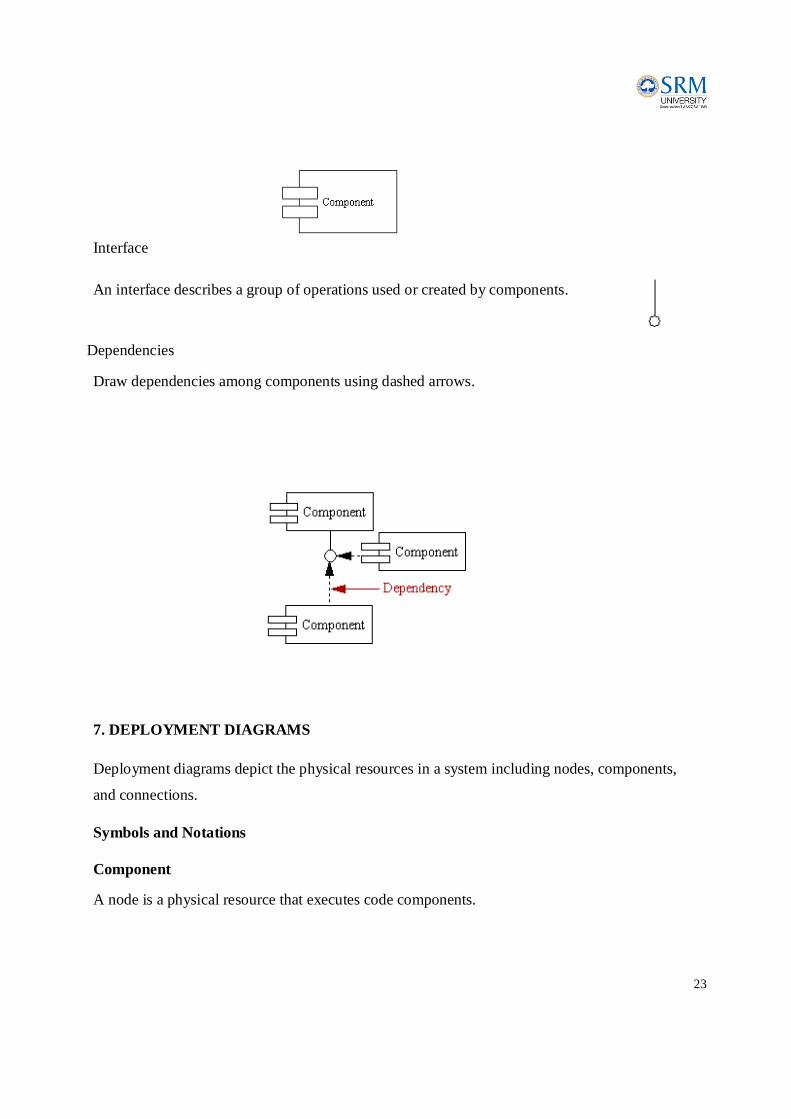
A component is a physical building block of the system. It is represented as a rectangle with tabs.
23
Interface
An interface describes a group of operations used or created by components.
Dependencies Draw dependencies among components using dashed arrows.
7. DEPLOYMENT DIAGRAMS
Deployment diagrams depict the physical resources in a system including nodes, components,
and connections. Symbols and Notations
Component
A node is a physical resource that executes code components.
24
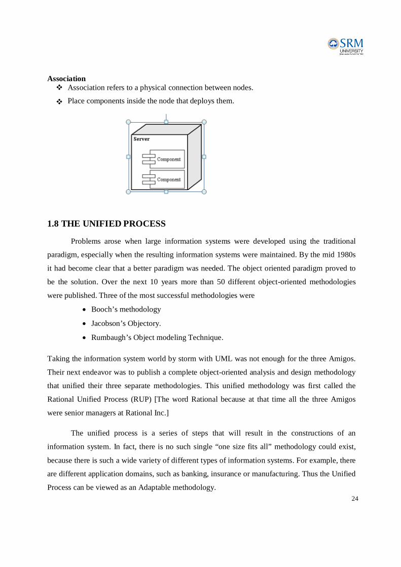
Association Association refers to a physical connection between nodes.
Place components inside the node that deploys them.
1.8 THE UNIFIED PROCESS
Problems arose when large information systems were developed using the traditional
paradigm, especially when the resulting information systems were maintained. By the mid 1980s
it had become clear that a better paradigm was needed. The object oriented paradigm proved to
be the solution. Over the next 10 years more than 50 different object-oriented methodologies
were published. Three of the most successful methodologies were
Booch’s methodology
Jacobson’s Objectory.
Rumbaugh’s Object modeling Technique. Taking the information system world by storm with UML was not enough for the three Amigos.
Their next endeavor was to publish a complete object-oriented analysis and design methodology
that unified their three separate methodologies. This unified methodology was first called the
Rational Unified Process (RUP) [The word Rational because at that time all the three Amigos
were senior managers at Rational Inc.]
The unified process is a series of steps that will result in the constructions of an
information system. In fact, there is no such single “one size fits all” methodology could exist,
because there is such a wide variety of different types of information systems. For example, there
are different application domains, such as banking, insurance or manufacturing. Thus the Unified
Process can be viewed as an Adaptable methodology.
25
1.9 ITERATIVE AND INCREMENTAL WITHIN THE UNIFIED PROCESS
The Unified Process is a modeling technique. A model is a set of UML diagrams that
represent one or more aspects of the information system wanted to be developed. A major reason
for using a graphical representation is that UML diagrams enable information technology
professionals to communicate with one another more quickly and more accurately than if only
verbal descriptions were used.
The Unified Process is an iterative and incremental methodology. Each workflow
consists of a number of steps and in order to carry out that workflow, the steps of the workflow
are repeated until the members of the development team are satisfied that they have an accurate
UML model of the information system they want to develop. The implication is that system
analysts, no matter how outstanding they may be, almost never get the object-oriented analysis
and design right the first time.
It is been subjected to Miller’s law-that one cannot think about everything at the same
time, so a set of seven chunks or so can be handled at once and then another set where the
developer can gain more knowledge about the information system and modify the UML
diagrams in light of the additional information. Thus more knowledge about the real-world
system is gained to make more accurate (iteration) and is extended accordingly (incrementation)
until accurate representation of the information system is developed.