UNIGEN 2.0 ILS - CRE TECHNOLOGY · UNIGEN 2.0 ILS Slave Load Sharing Unit USER MANUAL – TECHNICAL...
92
UNIGEN 2.0 ILS Slave Load Sharing Unit USER MANUAL – TECHNICAL DOCUMENTATION Part Number: A51V1 9 0020 A EN Last Update: January 2017
Transcript of UNIGEN 2.0 ILS - CRE TECHNOLOGY · UNIGEN 2.0 ILS Slave Load Sharing Unit USER MANUAL – TECHNICAL...

UNIGEN 2.0 ILS
Slave Load Sharing Unit
USER MANUAL – TECHNICAL DOCUMENTATION
Part Number: A51V1 9 0020 A EN Last Update: January 2017

User manual – technical documentation A51 V1 9 0020 A EN
2
Technical documentation history
Date Version Comment
January, 2017 A Initial edition

A51 V1 9 0020 A EN User manual – technical documentation
3
Preamble
SETTINGS The tables whose header have an orange-coloured background describe settings. Settings (and readings) that show only in CRE Config, but not on the LCD, feature a purple border in the HMI chapter as follows:
Setting Label Description
xxxx xxx Can be set in any HMI
xxxx xxx Can be set only in CRE Config
The setting content is referred to as [xxxx].
In the illustrations:
Digital inputs and outputs – whether direct or through CANopen – whose assignment is preset in the CRE Config software application show as follows; the shown position has no meaning.
Internal toggles preset through software show as switches with two throws. The code xxxx or the name of the setting shows above:
SYMBOLOGY
Denotes a threshold monitoring
Denotes a control loop tuning (three coefficients G, P, I)
Denotes the need to adjust the amplitude and offset (center)
CRE Technology believes that all information provided herein is correct and reliable and reserves the right to update at any time. CRE Technology does not assume any responsibility for its use. You can download the most up-to-date version of this documentation and different other documentations relating to UNIGEN 2.0 on our web site http://www.cretechnology.com.
Digital input
Digital output
xxxxassignment assignment

User manual – technical documentation A51 V1 9 0020 A EN
4
Content
1 Presentation ......................................................................................................................... 7
1.1 Generator automatic control ...................................................................................................... 8
1.2 Human machine interface ........................................................................................................... 9
1.3 Start and power management .................................................................................................. 10
1.4 Setting and supervision utility ................................................................................................... 10
2 Installation ......................................................................................................................... 11
2.1 On-desk-ethernet setup ............................................................................................................ 11
2.1.1 Setting the PC connection ............................................................................................. 11
2.1.2 Changing the UNIGEN 2.0 IP address ............................................................................ 12
2.1.3 Hostname ...................................................................................................................... 12
2.1.4 Copyright ....................................................................................................................... 12
2.2 In-panel installation ................................................................................................................... 13
2.2.1 Unpacking ...................................................................................................................... 13
2.2.2 Installation ..................................................................................................................... 13
2.2.3 Wiring the unit............................................................................................................... 14
2.2.4 Connection diagrams ..................................................................................................... 19
3 Applications ........................................................................................................................ 21
3.1 First start ................................................................................................................................... 22
3.2 Power management .................................................................................................................. 23
3.2.1 Load sharing .................................................................................................................. 23
3.2.2 Droop ............................................................................................................................. 25
3.2.3 Load-dependant start/stop ........................................................................................... 26
3.3 Loading and unloading ramp ..................................................................................................... 28
3.3.1 Configuration ................................................................................................................. 28
3.3.2 Tuning ............................................................................................................................ 29
3.4 Automatic frequency/voltage centering ................................................................................... 29
3.4.1 Use cases ....................................................................................................................... 29
3.4.2 Settings .......................................................................................................................... 29
3.4.3 Functioning .................................................................................................................... 29
3.5 Start by static paralleling ........................................................................................................... 31
3.5.1 Use cases ....................................................................................................................... 31
3.5.2 Conditions ...................................................................................................................... 31
4 Operation ........................................................................................................................... 34
4.1 Protections ................................................................................................................................ 34
4.1.1 General .......................................................................................................................... 34
4.1.2 Audio or visual annunciator .......................................................................................... 34
4.2 Potential Alarms/Faults catalog ................................................................................................ 35
4.2.1 Generator electrical fault .............................................................................................. 35
4.2.2 Engine and battery ........................................................................................................ 35

A51 V1 9 0020 A EN User manual – technical documentation
5
4.2.3 Analog inputs ................................................................................................................. 35
4.2.4 Communication ............................................................................................................. 36
4.2.5 Reset .............................................................................................................................. 36
4.3 Breaker management ................................................................................................................ 36
5 Commissioning ................................................................................................................... 37
5.1 Introduction ............................................................................................................................... 37
5.2 Analog speed governor output ................................................................................................. 38
5.3 Analog AVR (Auto Voltage Regulator) control .......................................................................... 40
5.4 Speed/voltage controlled by contacts/pulses ........................................................................... 42
5.4.1 Setup .............................................................................................................................. 42
5.4.2 Speed calibration procedure ......................................................................................... 43
5.4.3 Voltage calibration procedure ....................................................................................... 43
5.5 Tests .......................................................................................................................................... 43
5.5.1 Individual check ............................................................................................................. 43
6 Human-machine interface ................................................................................................... 45
6.1 Security and operations through the front panel ..................................................................... 45
6.1.1 Security level and password .......................................................................................... 45
6.1.2 HMI status ..................................................................................................................... 46
6.1.3 Navigation in LCD .......................................................................................................... 46
6.1.4 Edition............................................................................................................................ 47
6.2 Supervision ................................................................................................................................ 47
6.3 Web server ................................................................................................................................ 48
6.4 Menu visualisation .................................................................................................................... 49
6.5 CONFIGURATION menu ............................................................................................................. 51
6.6 SYSTEM menu ............................................................................................................................ 56
6.7 DEDICATED PAGES ..................................................................................................................... 59
6.7.1 Faults and alarms........................................................................................................... 59
6.7.2 Information .................................................................................................................... 59
7 Communication buses ......................................................................................................... 60
7.1 Modbus TCP .............................................................................................................................. 60
7.1.1 Capabilities .................................................................................................................... 60
7.1.2 Configuration ................................................................................................................. 60
7.1.3 Description .................................................................................................................... 60
7.2 CANopen extension modules .................................................................................................... 63
7.2.1 Hardware ....................................................................................................................... 63
7.2.2 Configuration ................................................................................................................. 64
7.2.3 Mapping......................................................................................................................... 64
7.3 J1939 Communication ............................................................................................................... 65
7.3.1 Overview ........................................................................................................................ 65
7.3.2 Search engines list ......................................................................................................... 65

User manual – technical documentation A51 V1 9 0020 A EN
6
8 Resources for setup & maintenance .................................................................................... 67
8.1 File transfer ............................................................................................................................... 67
8.1.1 UNIGEN 2.0 -> PC file transfer ....................................................................................... 67
8.1.2 PC -> UNIGEN 2.0 file transfer ....................................................................................... 68
8.1.3 Firmware upgrade ......................................................................................................... 68
8.2 Text file descriptioN .................................................................................................................. 68
8.2.1 Variable naming ............................................................................................................. 68
8.2.2 Text file description ....................................................................................................... 69
8.3 I/O lines ..................................................................................................................................... 71
8.3.1 Digital inputs .................................................................................................................. 71
8.3.2 Digital and relay outputs ............................................................................................... 73
8.3.3 Analog inputs ................................................................................................................. 75
9 Maintenance ...................................................................................................................... 77
9.1 Upgrading the software............................................................................................................. 77
9.2 Adding a custom HMI language ................................................................................................ 77
9.3 Troubleshooting ........................................................................................................................ 77
10 APPENDIX ........................................................................................................................... 81
10.1 Protection against short circuits ............................................................................................... 81
10.2 MTU J1939 communication....................................................................................................... 86
10.3 CAN bus good practices ............................................................................................................. 87
10.4 Control Loop Tuning .................................................................................................................. 89
10.5 Potentiels Alarms-faults Table .................................................................................................. 90

A51 V1 9 0020 A EN User manual – technical documentation
7
1 PRESENTATION
UNIGEN 2.0 ILS is a panel mounting electronic unit meant for the control of a single, two or three-phase low-voltage generator. It is designed to work as a slave of a PLC unit. UNIGEN 2.0 ILS can be used to control one generator included in a power plant (only load sharing – up to 32 generators).
UNIGEN 2.0 capabilities include:
PMS ILS SYNCHRO
Acquisition of the engine speed and the generator AC voltages x x x
Acquisition of the generator AC currents x x
Generator electrical protections x x x
PID control in load sharing mode x x
Control of actuators ; it is compatible with most speed governors (ESG) and AVR regulators
x x x
Synchronization before coupling x x
Analog inputs for reading resistive sensors x x x
Extension by CANopen units (Wago, Beckhoff, VIPA, etc) : up to 32 extra digital inputs and 32 extra digital outputs
x x x
Link to a PLC or a SCADA via Modbus TCP x x x
The engine-generator may have an Electronic Control Unit with CAN J1939 interface. J1939 and CANopen interfaces can coexist – on a second CAN media – provided they use the same bit-rate. According to the settings, the engine speed is measured by a magnetic pick-up or derived from the AC frequency.
Limits on overall active and reactive powers: 65,535 kW and 65,535 kVAR.
In this typical setup, three UNIGEN 2.0 units communicate over a CAN bus to control three generators in parallel:

User manual – technical documentation A51 V1 9 0020 A EN
8
Heterogeneous aggregate of generators in island mode can be controlled by UNIGEN 2.0 modules. It is preferred that the alternator winding pitches be identical. In any case, all the generators must be controlled by similar UNIGEN 2.0 units.
1.1 GENERATOR AUTOMATIC CONTROL
Two separate cascade control systems are used:
Primary control (UNIGEN) Secondary control
Speed ESG control ECU or ESG
Voltage AVR control AVR
The generated voltages and currents are measured in true RMS and used to calculate the load demand across the aggregate. The load demand drive the primary control which, according to its configuration:
Produces an analog signal Speed out+, sends pulses “+/- f” to digital outputs or writes to J1939 bus.
Produces an analog signal AVR out+ or sends pulses “+/- U” to digital outputs.

A51 V1 9 0020 A EN User manual – technical documentation
9
1.2 HUMAN MACHINE INTERFACE
LCD screen characteristics:
Size: 40 x 70mm - 1.50 x 2.75in
Pixels: 64 x 128
Back light: 50 cd/m2 typical, configurable
Contrast: configurable
Type: STN Back-lit auto-off LCD
The led blinks after a fault arises. Acknowledged by pressing the lower button
The led blinks after an alarm arises. Acknowledged by pressing the lower button
Press to access:
.the Fault page if new fault occurred (Fault blinks) .the Alarm page if new alarm occurred (Al. blinks) .pages with 2 statuses (Power and Engine) and 10 readings of special interest.
Press again to return.
Led Gen. ready Navigation/Edition
(see below)
GeneratorBreaker status led
(lit when closed)
Keyboard:
Keys Navigation mode Edition mode
Cyclic navigation through menu & settings list Used to change the value of a setting. Hold down to change
faster
Cyclic navigation through pages when an item is selected in a menu and validated
–
Shift Used with to in/decrease LCD luminosity
Used with to adjust LCD contrast
When in manual mode and breaker is open, used with to
increase/decrease:
speed command on Speed control page
voltage command on Voltage control page
Used with to reset alarms and faults
Esc Return to parent menu (3 times to home) or
preceding menu
Setting change rejection and return to the Navigation mode
Enter Page opening / switch to Edition mode Validation of the new setting and return to Navigation mode

User manual – technical documentation A51 V1 9 0020 A EN
10
1.3 START AND POWER MANAGEMENT
UNIGEN 2.0 units in an aggregate share information through CAN bus communication. Various start strategies can be implemented to match your needs:
In dynamic paralleling, the generators are selectively started and synchronized to the already running units. Then they can be stopped and restarted according to the load demand (“Load-Dependent Start-Stop”).
In static paralleling (emergency start), the generators are started simultaneously and the warm-up is by-passed.
1.4 SETTING AND SUPERVISION UTILITY
A Windows™ PC with the software application CRE Config 2.70 or later must be connected on the rear Ethernet socket, generally via a switch in a star network:
This allows you to preset all the UNIGEN 2.0 units when they are on desk: a text file that reflects the first UNIGEN 2.0 unit’s configuration can serve as a template to deploy the setup to the other UNIGEN 2.0 units in the cluster. The CRE Config multi-tabbed interface makes it easy.
Once all UNIGEN 2.0 units are mounted, CRE Config can be used to set them up and monitor the generators. The CRE Config features a Scada section that can be used in particular as an event console to UNIGEN 2.0:
UNIGEN 2.0 CRE Config/Scada
Even
t co
nso
le
Time Label Variable State
0h00 Breaker fault xxxx 1
Info
rmat
ion
dis
pla
y
Information
Power Engine Prod request 1 Mode AUTO
Label Variable Value
Prod request xxxx 1
Mode xxxx AUTO
Even
t lo
gger
2,000
2
1

A51 V1 9 0020 A EN User manual – technical documentation
11
2 INSTALLATION
2.1 ON-DESK-ETHERNET SETUP
2.1.1 Setting the PC connection
Connect UNIGEN 2.0 to a PC with a 100 Ethernet cord
Direct connection to PC: use a crossover cord.
Connection through a switch: use a direct cord; a crossover cord such as 3-m long A53W1 is OK if the switch manages it.
Power up UNIGEN 2.0 using a stabilized power supply
Power supply range: 8…35VDC
Open Windows control panel
Click:
Local network (Windows XP)
Network and Sharing Center / View status (Windows Vista)
Open Network and Sharing Center/Change adapter settings/(Connection to) LAN/ Properties (Windows 7 & 8)
Click Parameters (Windows XP) or Properties (Windows Vista or 7 or 8)

User manual – technical documentation A51 V1 9 0020 A EN
12
Select TCP/IP or TCP/IP v4, and click Properties
Enter a PC address that differs from the one of the UNIGEN 2.0 only by the last number, & click OK
Last number: 0 … 255; avoid 0 and 255 as they are often taken for other purposes
2.1.2 Changing the UNIGEN 2.0 IP address
To change UNIGEN 2.0 IP address, in CRE Config (or on LCD), navigate to “System/Network configuration (resp. About)”. UNIGEN 2.0 supports the DHCP function: in this case, UNIGEN 2.0 must be connected on a network with a DHCP server. During the power-on sequence, UNIGEN 2.0 is assigned an IP address by the DHCP server. If DHCP process fails, the fixed IP address is used (factory setting: 192.168.11.1).
Note: Contact your network administrator to configure your router and module(s) to your needs.
2.1.3 Hostname
You can assign an alias to UNIGEN 2.0, in addition to the IP address; enter it in CRE Config to get connected. To change this alias, in CRE Config navigate to System/Network configuration. Maximum length: 16 characters. With Windows, the last character defines the type of service (0 is the usual value). Allowed characters: reduced ANSI set; "-" and "." are allowed except at the start and end.
2.1.4 Copyright
UNIGEN 2.0 Ethernet communication uses the open source lwIP TCP-IP stack. Read copyright/disclaimer below. More details on lwIP Web site: http://savannah.nongnu.org/projects/lwip/ Copyright © 2001-2004 Swedish Institute of Computer Science. All rights reserved.
Redistribution and use in source and binary forms, with or without modification, are permitted provided that the following conditions are met: 1. Redistributions of source code must retain the above copyright notice, this list of conditions and the following disclaimer. 2. Redistributions in binary form must reproduce the above copyright notice, this list of conditions and the following disclaimer in the documentation and/or other materials provided with the distribution. 3. The name of the author may not be used to endorse or promote products derived from this software without specific prior written permission.
THIS SOFTWARE IS PROVIDED BY THE AUTHOR ``AS IS'' AND ANY EXPRESS OR IMPLIED WARRANTIES, INCLUDING, BUT NOT LIMITED TO, THE IMPLIED WARRANTIES OF MERCHANTABILITY AND FITNESS FOR A PARTICULAR PURPOSE ARE DISCLAIMED. IN NO EVENT SHALL THE AUTHOR BE LIABLE FOR ANY DIRECT, INDIRECT, INCIDENTAL, SPECIAL, EXEMPLARY, OR CONSEQUENTIAL DAMAGES (INCLUDING, BUT NOT LIMITED TO, PROCUREMENT OF SUBSTITUTE GOODS OR SERVICES; LOSS OF USE, DATA, OR PROFITS; OR BUSINESS INTERRUPTION) HOWEVER CAUSED AND ON ANY THEORY OF LIABILITY, WHETHER IN CONTRACT, STRICT LIABILITY, OR TORT (INCLUDING NEGLIGENCE OR OTHERWISE) ARISING IN ANY WAY OUT OF THE USE OF THIS SOFTWARE, EVEN IF ADVISED OF THE POSSIBILITY OF SUCH DAMAGE.

A51 V1 9 0020 A EN User manual – technical documentation
13
2.2 IN-PANEL INSTALLATION
The unit is designed for panel mounting, which provides user with access only to the front panel.
WARNING
THE UNIT IS NOT GROUNDED Take all measures against Electronic Static Discharges.
Do not try to open the unit.
Failure to follow these instructions may damage the unit
Environmental requirements:
Operating temperature: -30°C (-22°F) … 70°C (158°F); LCD display slows down a bit under -5°C (23°F). Avoid direct exposure to the sun
Storage temperature: -40°C (-40°F) … 80°C (176°F)
Altitude: up to 2,000 m (6,561 ft); on higher altitudes, recommended max. AC voltage : 100VAC
2.2.1 Unpacking
Make sure the packaging contains:
the unit
four caps + screws packaged apart
a delivery bill
Unpack and keep the packaging in event of return. Make sure the unit does not show scratches or visible defaults. Otherwise describe them on the RMA sheet (downloadable from CRE technology Web site).
2.2.2 Installation
Preparation
1. Cut out the panel to 220x160 mm minimum (8.7 in x 6.3 in) 2. Make sure the cut-out is smooth and clean
Mounting
0 Tool: cross-head screwdriver size 1
1 Pass the unit through the panel
2 In the rear, cover each of the four spacers with a cap
3 Screw a cap against the panel
4 Repeat on the diagonally opposite spacer
5 Repeat on the other diagonal and tighten equally (do not overtighten)

User manual – technical documentation A51 V1 9 0020 A EN
14
2.2.3 Wiring the unit
Tool: insulated screwdriver Ø2.5 mm (0.1 in), tightening torque: 0.8 Nm (7 lb-in) max.
Accessories: 4, 5, 6, 8, 15 & 18-terminal cable connectors, protective gloves, carpet if the floor is wet.
WARNING
THE UNIT IS NOT PROTECTED
Use external fuses: Bus bar and Generator phases: 100mA/600VAC Battery positive: 5A/40VDC
Install the fuses as near as possible the unit, in a place easily accessible to the user.
The disconnection device must NOT be fitted in a flexible cord.
Failure to follow these instructions may damage the unit
General procedure
1. Make sure the cable connectors are NOT plugged
2. Take on protective gloves
3. Connect the wires on each cable connector in accordance with the National Wiring Regulations
4. Plug each cable connector onto the related connector
1. 5. Plug a direct Ethernet cord (RJ45, male-male, 100 m max., 100; a crossover cable such as 3-m long A53W1 is OK if the switch manages it or if the link to PC is direct) and lock the rear door.
Recommandations
Wires section: 2.5 mm² (AWG13). To avoid ElectroMagnetic Interferences, shield cables appropriately; for CAN bus, see the Appendix CAN bus Good practices. Segregation: keep power cables separate from the CAN bus cables. The latter can be installed in the same duct as the low level DC I/O wires (under 10V).
If power & communication cables have to cross each other, do it at right angles to avoid crosstalk:
DANGER
HAZARD OF ELECTRIC SHOCK, EXPLOSION OR ARC FLASH The unit must only be installed and serviced by qualified electrical personnel Apply appropriate personal protective equipment (PPE) & follow safe electrical work practices Turn off power before installing or removing fuses, and before installing the unit Use a properly rated voltage sensing device to confirm the power is off Do not use renewable link fuses in fused switch
Failure to follow these instructions will result in death or serious injury
ll
!

A51 V1 9 0020 A EN User manual – technical documentation
15
Overview
Relay
outputs
Gen AC voltages
Generator currents
Analog inputs
8-35VDC / Digital outputs / Digital inputs CAN2 Speed / AVR CAN1 Pick-up
output
User manual – technical documentation A51 V1 9 0020 A EN
16
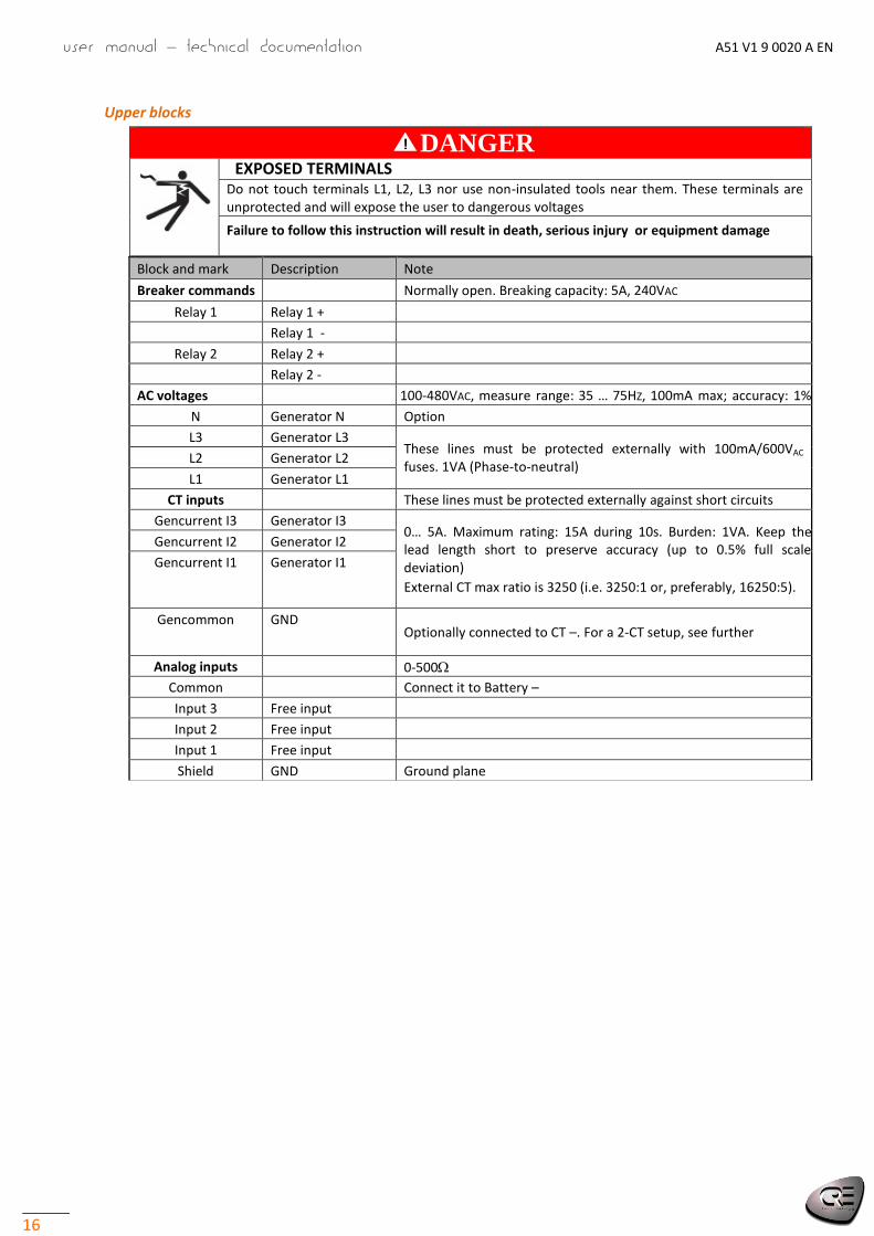
Upper blocks
Block and mark Description Note
Breaker commands Normally open. Breaking capacity: 5A, 240VAC
Relay 1 Relay 1 +
Relay 1 -
Relay 2 Relay 2 +
Relay 2 -
AC voltages 100-480VAC, measure range: 35 … 75HZ, 100mA max; accuracy: 1% fsd N Generator N Option
L3 Generator L3 These lines must be protected externally with 100mA/600VAC fuses. 1VA (Phase-to-neutral)
L2 Generator L2
L1 Generator L1
CT inputs These lines must be protected externally against short circuits
Gencurrent I3 Generator I3 0… 5A. Maximum rating: 15A during 10s. Burden: 1VA. Keep the lead length short to preserve accuracy (up to 0.5% full scale deviation)
External CT max ratio is 3250 (i.e. 3250:1 or, preferably, 16250:5).
Gencurrent I2 Generator I2
Gencurrent I1 Generator I1
Gencommon GND Optionally connected to CT –. For a 2-CT setup, see further
Analog inputs 0-500
Common Connect it to Battery –
Input 3 Free input
Input 2 Free input
Input 1 Free input
Shield GND Ground plane
DANGER
EXPOSED TERMINALS Do not touch terminals L1, L2, L3 nor use non-insulated tools near them. These terminals are unprotected and will expose the user to dangerous voltages
Failure to follow this instruction will result in death, serious injury or equipment damage
ll
!

A51 V1 9 0020 A EN User manual – technical documentation
17
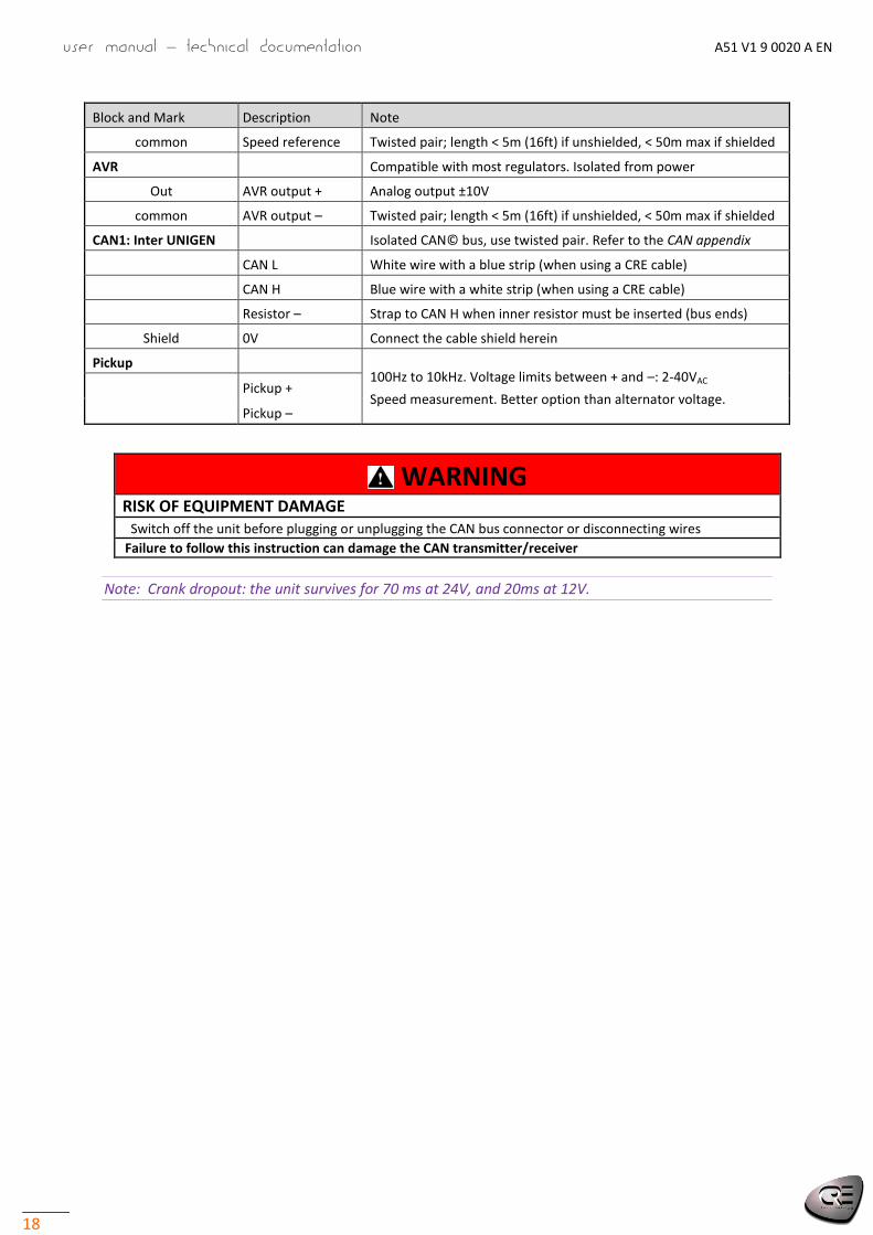
Lower blocks
WARNING
RISK OF EQUIPMENT DAMAGE As a protection against polarity reversal, install a 6A fuse between Battery positive lug & terminal 8-35VDC +.
Connect battery negative to GENSYS terminal 8-35VDC– with 2.5 mm² (AWG13) cable.
Failure to follow this instruction can damage the controller
Block and Mark Description Note
8-35VDC NOT protected against polarity reversal
- Power supply - 2.5mm² (AWG13)
+ Power supply + 8…35VDC, consumed current: 130 mA at 24V (standby & operation)
Shield GND Generator chassis
Digital outputs
Free solid state output. State 1 at the supply voltage (max: 1.8A). Protected against short circuits. A reactive load is supported. Not isolated from power.
1
Free ouputs
2
3
4
5
6
Digital inputs
Free digital input with 10kΩ pull-up.
Accepts NO or NC contact to 0V.
Not isolated from power.
1 GE breaker feedback
2
Other free inputs
3
4
5
6
7
8
9
CAN2: J1939-Extensions Isolated CAN bus J1939/CANopen. Twisted pair. See CAN appendix
CAN L Blue wire
CAN H White wire
Resistor – Strap to CAN H when inner resistor must be inserted (bus ends)
Shield 0V Connect the cable shield herein
Speed Compatible with most speed governors. Isolated from power
Out Speed output ±10V analog output to speed governor
User manual – technical documentation A51 V1 9 0020 A EN
18
Block and Mark Description Note
common Speed reference Twisted pair; length < 5m (16ft) if unshielded, < 50m max if shielded
AVR Compatible with most regulators. Isolated from power
Out AVR output + Analog output ±10V
common AVR output – Twisted pair; length < 5m (16ft) if unshielded, < 50m max if shielded
CAN1: Inter UNIGEN Isolated CAN© bus, use twisted pair. Refer to the CAN appendix
CAN L White wire with a blue strip (when using a CRE cable)
CAN H Blue wire with a white strip (when using a CRE cable)
Resistor – Strap to CAN H when inner resistor must be inserted (bus ends)
Shield 0V Connect the cable shield herein
Pickup 100Hz to 10kHz. Voltage limits between + and –: 2-40VAC
Speed measurement. Better option than alternator voltage. Pickup +
Pickup –
WARNING
RISK OF EQUIPMENT DAMAGE Switch off the unit before plugging or unplugging the CAN bus connector or disconnecting wires
Failure to follow this instruction can damage the CAN transmitter/receiver
Note: Crank dropout: the unit survives for 70 ms at 24V, and 20ms at 12V.

A51 V1 9 0020 A EN User manual – technical documentation
19
Other systems of voltage
If Biphase 180° is selected in CRE Config, connect voltages and currents to terminals L1-L3 (and N), resp. I1-I3 (and common).
If Monophase is selected, connect voltages and currents to the terminals L1-N, resp. I1 and common.
Current measurement by only two CTs
The 3-phase system must be balanced; therefore I3= – I1 –I2 and only two identical CTs are required:
This is used in middle-high voltage applications. The I3 value is less accurate.
2.2.4 Connection diagrams
These diagrams show that the Potential Transformers can be connected in various ways:
Star (wye) on generator side (1 insulated high-voltage terminal per PT) ; the ratio is for example
√
√
Vee on bus side (2 insulated high-voltage terminals per PT) ; the ratio is for example

User manual – technical documentation A51 V1 9 0020 A EN
20

A51 V1 9 0020 A EN User manual – technical documentation
21
3 APPLICATIONS
Each generator in the aggregate is controlled by a dedicated UNIGEN 2.0 PMS unit. All UNIGEN 2.0 PMS units are CAN-connected. A typical configuration for paralleling is the following:
Starting from the default settings, just enter the installation specification :
Setting Label Value
2000 Count of gen. 1 ≤ N ≤ 32
2001 GE Number 1 to 32 (differs for each UNIGEN 2.0 on the CAN bus)
Setting Label Value
2050 Paralleling mode Unused [0], Static [1]
Digital inputs
Mandatory
Generator breaker feedback Optional
Load request
User manual – technical documentation A51 V1 9 0020 A EN
22
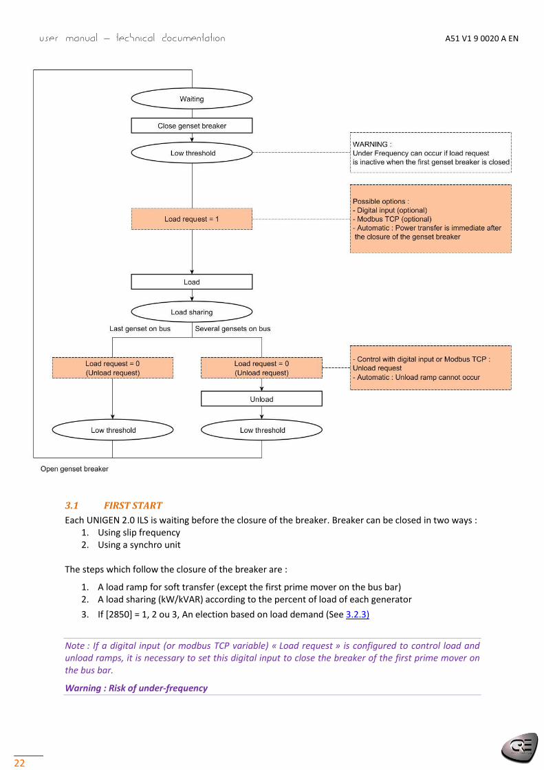
3.1 FIRST START
Each UNIGEN 2.0 ILS is waiting before the closure of the breaker. Breaker can be closed in two ways : 1. Using slip frequency 2. Using a synchro unit
The steps which follow the closure of the breaker are :
1. A load ramp for soft transfer (except the first prime mover on the bus bar) 2. A load sharing (kW/kVAR) according to the percent of load of each generator
3. If [2850] = 1, 2 ou 3, An election based on load demand (See 3.2.3)
Note : If a digital input (or modbus TCP variable) « Load request » is configured to control load and unload ramps, it is necessary to set this digital input to close the breaker of the first prime mover on the bus bar.
Warning : Risk of under-frequency

A51 V1 9 0020 A EN User manual – technical documentation
23
3.2 POWER MANAGEMENT
3.2.1 Load sharing
UNIGEN 2.0 is informed of the other generators’ loads through the CAN bus; they share the load in proportion to their power rating. This strategy is more reliable and accurate than an analog solution.
The speed control is used to share the active load. The AVR control is used to share the reactive load. Various readings are available:
Label Description
kW GEx Percent of nominal active power supplied by each generator (variables 400 to 431)
kVAR GEx Percent of nominal reactive power supplied by each generator (variables 465 to 496)
Nom kW GEx Nominal active power supplied by each generator (variables 433 to 464)
Nom kVAR GEx Nominal reactive power supplied by each generator (variables 498 to 529)
The shares taken by the generators are monitored on CRE Config or LCD screen.
Setting Label Description
3708 Uneven kW lvl Threshold (in %) for the generator active power
3709 Unev. kW delay Delay before raising fault
3711 Unev. kVAR lvl Threshold (in %) for the generator reactive power
3712 Unev. kVAR dly Delay before raising fault
The statuses and actions on alarm are as follows (the potential actions are listed in the chapter Operation/Protections):
Status Label On alarm Description
4263 Uneven kW 3710 Generator active power is far from the average of all active powers
4264 Uneven kVAR 3713 Generator reactive power is far from the average of all reactive powers
If one generator needs to be set to a fixed setpoint, you can isolate it from the rest of the power plant by withdrawing its UNIGEN 2.0 unit from CAN bus communication, using either method:
Set the digital input Inhibit Gen [4557 … 4588] to 1
Change the variable [4557 … 4588] via Modbus TCP
Generator share
Deviation
t
kW/kVAR
dly
Average power
%lvl
Uneven signal

User manual – technical documentation A51 V1 9 0020 A EN
24
Tuning
Prerequisites:
Speed out & AVR outputs are scaled to match the generator. See 5.2 and 5.3.
At least two generators are synchronized.
Factor Setting Label Default
kW sharing P 2917 Load sharing P 20
I 2918 Load sharing I 1
kVAR sharing P 2959 Share Q P 20
I 2960 Share Q I 1
Once the setting of synchronization and ramp has been done, you can adjust the load sharing. kW and kVAR share stays within 2% of that power plant average.
Note: The kW/kVAR power plant average in % as well as the kW/kVAR of the genset in % can be visualized on the LCD screen during the configuration of the PID
You can change :
Proportionnal : to decrease the correction time
Integral : to decrease load sharing difference
Note: Integral is used only if the frequency/voltage centering is set (See 3.4).

A51 V1 9 0020 A EN User manual – technical documentation
25
3.2.2 Droop
In event of a CAN bus failure, speed droop and voltage droop are allowed to share kW load and kVAR load respectively. As droop is allowed, the control does not use any integral. Frequency droop The droop is the allowed relative offset:
Speed Droop = (Rated no-load frequency – Base frequency)/ Rated no-load frequency In the aggregate the generators were requested to run in proportion to their rated power i.e. with the same P/P0. As they are set with the same droop, they share the same droop characteristic. As the load demand increases, they respond to the fall in frequency by increasing their active power outputs simultaneously. The increase in the active power output counteracts the reduction in frequency. Thus they do not fight one another to control the load (no "hunting").
Voltage droop uses voltage in place of frequency The droops are set in the UNIGEN 2.0 units, not in the ESGs/AVRs:
If 3052 is set to 8 or 9 on all the UNIGEN 2.0 units, all the generators fall back to speed and voltage droops. It matters that all the UNIGEN 2.0 units be set to the same relative deviations 2204 and 2250.
Setting Label Description
2204 Speed droop % for active load sharing. Default value: 2%
2250 Voltage droop % for reactive load sharing. Default value: 2%
3052 CAN bus fault 8 or 9
AVERTISSEMENT Follow strictly, throughout the aggregate, the scaling procedures (amplitude -offset) of chapter 5.2 & 5.3 in order to have the best load sharing in droop
0%: isochronous
1 P/P0
f0f
Speed droop=(f0-f)/f0
Droop characteristic
User manual – technical documentation A51 V1 9 0020 A EN
26
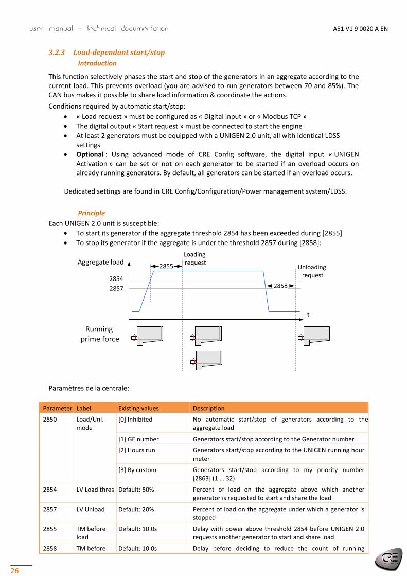
3.2.3 Load-dependant start/stop
Introduction
This function selectively phases the start and stop of the generators in an aggregate according to the current load. This prevents overload (you are advised to run generators between 70 and 85%). The CAN bus makes it possible to share load information & coordinate the actions.
Conditions required by automatic start/stop:
« Load request » must be configured as « Digital input » or « Modbus TCP »
The digital output « Start request » must be connected to start the engine
At least 2 generators must be equipped with a UNIGEN 2.0 unit, all with identical LDSS settings
Optional : Using advanced mode of CRE Config software, the digital input « UNIGEN Activation » can be set or not on each generator to be started if an overload occurs on already running generators. By default, all generators can be started if an overload occurs.
Dedicated settings are found in CRE Config/Configuration/Power management system/LDSS.
Principle
Each UNIGEN 2.0 unit is susceptible:
To start its generator if the aggregate threshold 2854 has been exceeded during [2855]
To stop its generator if the aggregate is under the threshold 2857 during [2858]:
Paramètres de la centrale:
Parameter Label Existing values Description
2850 Load/Unl. mode
[0] Inhibited No automatic start/stop of generators according to the aggregate load
[1] GE number Generators start/stop according to the Generator number
[2] Hours run Generators start/stop according to the UNIGEN running hour meter
[3] By custom Generators start/stop according to my priority number [2863] (1 … 32)
2854 LV Load thres Default: 80% Percent of load on the aggregate above which another generator is requested to start and share the load
2857 LV Unload Default: 20% Percent of load on the aggregate under which a generator is stopped
2855 TM before load
Default: 10.0s Delay with power above threshold 2854 before UNIGEN 2.0 requests another generator to start and share load
2858 TM before Default: 10.0s Delay before deciding to reduce the count of running
Aggregate load
2854
2857
t
2855
Loading request
Unloading request
2858
Running prime force

A51 V1 9 0020 A EN User manual – technical documentation
27
unload generators in load/unload management
Note: Preset values for Load-dependant start/stop can be loaded using the CRE Config software. Click
on and choose file « ILS_Load_dependant_start_stop.txt ».
Example: A 4x100kW aggregate with a load that increases linearly from 0 to 400kW, then decreases to 0kW. Start threshold 2854 is set to 80% & the stop threshold 2857 is set to 20%. Generator #1 is permanently running. When load increases above the start threshold, generator #2 starts to supplement generator #1, then generator #3 & generator #4 start. As the load decreases, the generators are phased out in the order 4, 3, 2.
Start-stop by generator number
If this way is selected on all UNIGEN 2.0 units in the power plant, the automatic start/stop phasing is based on the generator numbers, set in CRE Config/Configuration/Power [2001]:
1. The generator with the smallest number will start first and run onwards forcefully
2. On increasing load demand, the next starts are ruled by the generator number
3. On decreasing load demand, the generators are phased out in the reverse order.
Start-stop by running hours
In this way, the generator to start/stop is automatically selected according to the UNIGEN 2.0 running hour meter:
On increasing load demand, the next generator to start is the one with fewest running hours
On decreasing load demand, the next generator to stop is the one with most running hours
Note: If a generator starts and goes past the hours run by a generator which is stopped, the first one does not immediately stop and the second one does not immediately start. Coordination between generators is activated only on a load/unload request, i.e. in the next start/stop on-load request on the CAN bus.

User manual – technical documentation A51 V1 9 0020 A EN
28
Start-stop by generator priority number
If this way is selected on all UNIGEN 2.0 units in the power plant, the automatic start/stop phasing is based on the generator priority numbers, set in CRE Config/Configuration/Power manag system/LDSS [2863]:
1. The generator with the smallest number will start first and run onwards forcefully
2. On increasing load demand, the next starts are ruled by the generator priority number
3. On decreasing load demand, the generators are phased out in the reverse order.
3.3 LOADING AND UNLOADING RAMP
3.3.1 Configuration
After the closure of the breaker, UNIGEN 2.0 ramps up the generator load (soft transfer) to avoid overload or an abrupt load kick (hard transfer).
Note: The digital input « Load request » can be used for staying at low limit, after the synchronization and before the opening of the breaker at the end.
UNIGEN 2.0 calculates the average active power from the information conveyed by the Inter-UNIGEN 2.0 CAN bus. Then it starts a load ramp to reach progressively this value (kW regulation). During ramp, UNIGEN 2.0 keeps a constant power factor, set by the bus power factor before closing generator breaker, in order to do a reactive power ramp.
In the same way, when UNIGEN 2.0 must stop, an unload ramp is done.
Various settings are used in ramping up/down:
Example: Nominal power = 500kW Load (kW)
0
50
100
150
200
250
300
1 3 5 7 9 11 13 15 17 19 21 23 25 27 29 31 33 35 37 39 41 43 45 47 49 51 53 55 57 59 61
Time to ramp up
Time to ramp down
Active power set point
Low limit
Setting Label Default Description Example
2851 Generator low limit 10kW Wattage lower limit 50kW
2853 Loading ramp time 10.0s Time to ramp up power from 0 to nominal power 50s (slope: 10kW/s)
2856 Unloading ramp time 10.0s Time to ramp down power from nominal power to 0 22s (slope: 23kW/s)
t

A51 V1 9 0020 A EN User manual – technical documentation
29
Before isolating and stopping a generator, its UNIGEN 2.0 unit decreases its load from the current value to the low limit.
3.3.2 Tuning
Prerequisite: Speed out and AVR outputs are scaled to match the generator. See 5.2 et 5.3.
If the generator is in reverse power or does not take enough load, adjust P in menu “Configuration/ control loop /Ramp kW or kVAR” (0 … 200%).
Setting Label Description Default
2913 Ramp kW P Proportional of kW ramp 100
2967 Ramp kVAR P Proportional of kVAR ramp 100
Notes: You can monitor both kW/kVAR setpoints and measurements during the ramp. Integral is not used during ramps.
3.4 AUTOMATIC FREQUENCY/VOLTAGE CENTERING
3.4.1 Use cases
The secondary regulations (ESG and AVR) might drift, e.g. due to thermal variations. To counteract these effects, a strategy called frequency centering is applied by default in the aggregate. The same applies to voltage; the voltage centering can counteract a voltage drift. When it is used to counteract the droop created by the ESG/AVR, this strategy is called “de-drooping”.
3.4.2 Settings
Associated parameters are listed in the table below :
Setting Label Description Default value 2927 Hz center act Activation 1 (enabled)
2926 Hz center gain Central frequency gain of lead UNIGEN 1
2970 U center act Activation of central voltage 1 (enabled)
Procedure: 1. Start the engine and adjust the generator speed to get 49Hz by tuning the speed governor
offset 2. Close the breaker on a dead bus bar, the frequency must return to 50Hz within 5s 3. Adjust the Hz centering gain [2926] to adjust recovery time if needed 4. Adjust the generator speed to get 50Hz by tuning the speed governor offset 5. Repeat the steps for all generators
Note: load sharing integral is used only if the frequency/voltage centering is set.
3.4.3 Functioning
Using the CAN bus, the aggregate elects a leader among the generators on bus bar. The centering is applied only to the leader and requires no extra communications whether digital or analog.
For information, the leader number is indicated in [357] variable.

User manual – technical documentation A51 V1 9 0020 A EN
30
The centering is a slight proportional correction that slowly brings back the frequency and voltage to their nominal value. As a result, the leader takes more of the load. Through the load sharing loop of the other generators, the load balance is regained.
If the default tuning cannot counteract the drift, hone the tuning.

A51 V1 9 0020 A EN User manual – technical documentation
31
3.5 START BY STATIC PARALLELING
3.5.1 Use cases
Starting a full plant with multiple generators in an emergency on dead bus: the generators are ready to take load in the shortest possible time, without warm-up Bottom line: full plant availability in less than 10s typically. This meets the NEC700 requirements.
Installation with a high voltage transformer: as the generator(s) start, the transformer core is magnetized progressively, without peaks (no transient short-circuit).
3.5.2 Conditions
On equipment:
The alternators are identical (in particular, same winding pitch)
The AVRs are set for static paralleling: they wait for excitation command on their first start
All breakers must be powered by continuous voltage like 24VDC (so as to close before AC is available)
On UNIGEN 2.0: Digital inputs Digital outputs
Mandatory
Generator breaker feedback Optional
Load request
Mandatory
Excitation command

User manual – technical documentation A51 V1 9 0020 A EN
32
Setting Label Default Description
2050 Paralleling mode
Dynamic Set it to static
2200 Speed measure Pick-up Necessarily measured by pick-up
2201 Number of teeth
100 To configure
2051 TM max excit 30.0s Timeout for excitation
2053 Excit. speed 90.0% Speed low threshold in % of nominal speed before waiting excitation. This threshold must be identical in all UNIGEN 2.0 units
2056 TM Volt stab. 5.0s Voltage stabilization timer after excitation order before to pronounce as engine ready.
This timer must be identical in all UNIGEN 2.0 units. During this stabilization, the units are working in droop mode.
Note: Presets for Static paralleling can be load using the CRE Config software. Click on and choose the file « ILS_Static_paralleling.txt ».
The generators are synchronized together through the CAN bus:
Because UNIGEN 2.0 ILS is a slave module, the closure of the breaker and the start of the engine
need to be realized first. Then, all the UNIGEN 2.0 set their excitation command together :
1. Closure of the breakers (not controlled by UNIGEN 2.0) 2. Start of the engines (not controlled by UNIGEN 2.0) 3. The remanent voltage appears 4. Set « Load request » on each generator to be started (Can be set at the beginning) 5. When the speed is sufficient on every generators, CAN bus communication orders all
UNIGEN 2.0 units to simultaneously activate their excitation output; as a result:
The nominal voltage is reached immediately at the same time on all generators

A51 V1 9 0020 A EN User manual – technical documentation
33
Note: If the variable « Load request » is configured as automatic, UNIGEN 2.0 will set immediately their digital output « Excitation command » once a sufficient speed is reached.

User manual – technical documentation A51 V1 9 0020 A EN
34
4 OPERATION
4.1 PROTECTIONS
4.1.1 General
Protections are triggered by internal and external events (alarms, faults, digital inputs, CAN bus loss …). To protect the process, the engine or the alternator, you must associate one of the predefined actions to each such event. These actions or effects are of various kinds:
they can just raise an alarm; notice shows on the front panel (ANSI30); a summary can be reported
they can secure the equipment: the breaker trips safe … and can activate a free protective digital output
The action is an attribute of the protection: CT settings, or of inter-module CAN bus loss. The Droop effect is reserved to CAN bus fault.
Value Action Description
0 Disable (no action) –
1 Generator electrical fault The protection opens generator breaker
3 Alarm Notice as alarm on front panel
8 Droop + Alarm Only available on CAN bus fault [3052]
The actions are configured in CRE Config. Numerical values show only in text file. See 8.2.
4.1.2 Audio or visual annunciator
To trigger an external annunciator whenever a protection trips, connect it to an output preset to the Horn function; the signal duration is modified by 2478; alternately, an input can be used for remote reset:
Horn
Stop horn
S
R
RS
OUT
Protection
t
2478
Setting Label Description
2478 Horn delay Duration of ring. Default value: 10s. 0 means the horn will buzz until being manually stopped

A51 V1 9 0020 A EN User manual – technical documentation
35
4.2 POTENTIAL ALARMS/FAULTS CATALOG
The potential alarms/faults are listed below.
Potential Alarm/Fault: Alarm/Fault label; this text shows in the Alarm/fault pages
Action on alarm/on fault: this variable allows you to define the associated protection type (3 potential values)
This list can be downloaded from CRE Config/System/PC transmit-receive/Action on alarm/fault”.
4.2.1 Generator electrical fault
(All protections trip after a definite time, except Short circuit which trips after an IDMT; see Appendice)
Potential Alarms/Faults ANSI Description On alarm On fault
Overfrequency 81H Generator is in over frequency 2402 2438
Underfrequency 81L Generator is in under frequency 2405 2441
Overvoltage 59 Generator is in over voltage 2408 2444
Undervoltage 27 Generator is in under voltage 2411 2447
Min kW 37P Generator reached a minimum of kW 2414 2450
Max kW 32P Generator reached a maximum of kW 2417 2453
-kW 32RP Generator is in reverse kW 2420 2456
Min kVAR 37Q Generator reached a minimum of kVAR 2423 2459
Max kVAR 32Q Generator reached a maximum of kVAR 2426 2462
-kVAR 32RQ Generator is in reverse kVAR 2429 2465
Max I 50 Generator is in over current 2432 (I>) 2468 (I>>)
Max In 50N Generator is in over neutral current 2435 (I0>) 2471 (I0>>)
Short circuit 51 Short circuit between generator phases – 2477
Phase measure – Generator voltage measurement is
inconsistent with configuration [2003] 2805 –
Uneven kW 90P See 4.2.1 3710 -
Uneven kVAR 90Q ibidem 3713 –
4.2.2 Engine and battery
4.2.3 Analog inputs
Potential Alarms/Faults Description On level 1/Min On level 2/Max
Min battery voltage Battery voltage under the minimum 2358 2376
Max battery voltage Battery voltage over the minimum 2361 2379
Sensor lost Triggered if the speed is 0 and engine has started
Potential Alarms/Faults Description On level 1/Min On level 2/Max
AN1 min/max Activated if measurement of analog input 1 is under/over the threshold 2602 2605
AN2 min/max Activated if measurement of analog input 2 is under/over the threshold 2610 2613

User manual – technical documentation A51 V1 9 0020 A EN
36
4.2.4 Communication
4.2.5 Reset
Clearing of faults/alarms: - Locally: Shift + - Remotely: use the “Fault reset” input function
4.3 BREAKER MANAGEMENT
UNIGEN 2.0 ILS does not allow to control directly the breaker. This needs to be done using an external product.
However, the digital output « Generator electrical faults summary » can be used to open the breaker when a protection configured as « Generator electrical fault » occurs.
The digital output « Low limit is reached » set after an unload ramp and can be used to open the breaker with an external module.
AN3 min/max Activated if measurement of analog input 3 is under/over the threshold 2618 2621
Potential Alarms/Faults Description On level 1/Min On level 2/Max
CAN1 bus fault Communication problem on the inter-unit CAN (only power plant applications)
3052 –
CAN2 bus fault A J1939/CANopen bus error is detected on CAN2. 3053 –
CANopen An alarm is activated to indicate a CANopen communication fault.

A51 V1 9 0020 A EN User manual – technical documentation
37
5 COMMISSIONING
5.1 INTRODUCTION
Each function produces a speed or voltage deviation based on its own GPI coefficients. UNIGEN 2.0 feeds the sum of deviations to the output stage either as analog signals (Speed out and AVR out+) or as pulses train or J1939 frames (speed):
[4405] is the sum of all applicable speed deviations due to:
kW regulation (Load ramp)
kW sharing
Frequency centering
Manual command
Speed droop (in event of CAN bus loss)
[4411] is the sum of all applicable voltage deviations due to:
kVAR regulation (Load ramp)
kVAR sharing
Voltage centering
Manual command
Voltage droop (in event of CAN bus loss)
In fact, not all components contribute to the sum at one time; the sequencing is Ramp->Load sharing (+centering), and can be followed with
Reading Label Description
4009 Power mode 0: Nothing 2: Droop 3: Load sharing 4: Ramp (very transient)
4010 AVR cont. mode
CAUTION Follow strictly, throughout the aggregate, the scaling procedures (amplitude -offset) to have the best
synchronization, load sharing and droop

User manual – technical documentation A51 V1 9 0020 A EN
38
5.2 ANALOG SPEED GOVERNOR OUTPUT
The Speed output signal provides the set point for ESG, used in active load sharing. It is the sum of the components listed in the section 5.1. The voltage range -10V …+10V must be fitted in amplitude and offset to allow UNIGEN 2.0 to vary the ESG set point on a correct range; the aim is that UNIGEN 2.0 can control the frequency in the +/-3Hz band around the nominal frequency:
F
+V
Am
pli
tud
e
Sum
3H
z
Nom
offset
3H
z
-V
1. Connect the speed common wire only
2. In “Configuration/Engine”, preset the amplitude and offset as described in the table further
(if not listed, contact CRE Technology)
ESG amplitude … V
ESG offset … V
F 50Hz
Engine Speed 1500
Speed Sum 0000
Lecture
Lecture
3. Start the generator
4. Trim the governor potentiometer to read 50Hz (or 60Hz)
5. Connect the Speed out signal; adjust the offset so that the frequency is 50Hz (or 60Hz)
6. Adjust Speed sum to +100% :
o Page “Configuration/Engine”
o With the Shift + keys , adjust the amplitude so that the frequency is 53Hz (or
63Hz)
7. Return to 0%; adjust the offset if needed to get back 50Hz (or 60Hz)
ESG amplitude Deviation
+ ESG offset
Speed out
Speed common

A51 V1 9 0020 A EN User manual – technical documentation
39
8. Select the Speed Sum and adjust it to –100% with the Shift + keys in order to check the
variation range till 47Hz (or 57Hz)
9. Adjust the speed sum to 0%.
The next table gives both settings for various ESGs. For other models, preset amplitude and
offset according the manufacturer documentation and/or contact our Customer service.
Manufacturer Model ESG ampl. ESG offset
ESG input ESG ref Note
BARBER COLMAN
with analog input 0.5V 0V ILS input 4V
DPG 2201
0.5V 0V ILS signal ILS+2.5V
The tuning depends
on the connections ILS signal
Digital
supply(+5V)
ILS signal BAT-
ECM for QSK23 /
QSK40 / QSK45 /
QSX15 / QSK 60
2.5V 0V
11 (Barber
Colman Freq.
bias input)
06 (5V)
EFC 1.5V 0V 8 9 See schematic
ECM (QST30) 18 15 (7,75V)
EMR 2V 2.5V 24 25
+/- 1.5 Hz not to reach
EMR overspeed
ESD5330 –5V M G
All other ESD –5V N G
GHANA CONTROL
PWC 2000 J G
E6 B3
KG6 / System E6 2.5V 2.5V E3 A3
PANDAROS DC6 2V 2.5V B3 A3
JDEC
2V 2.5V L C Two different wirings
for the same governor G2 5V(ref speed) 999
MDEC 4V 0V 8 36 & 7 (5V)
ECM 1300 2V 2.5V 30 5V
2 and 12 connected
for external setting
EDC IV
EDC III 1.5V 3V Pot. signal
- 2301A/D ILS+speed
- (Without U&I)
0V
3V
10
25
11
26
Shunt 14-16
Shunt 26 (com) on 0V
2301D
2301A Speed only 4.5V 2.5V 15 16 16 connected to 0V
EPG System
P/N 8290-189
P/N 8290-184
2.5V 0V 11 (0.6V) nc Remove the shunt between 11 and 12
Because of the very high sensitivity of Cummins EFC module input, use the schematic below to connect UNIGEN 2.0 to the EFC. The resistors must be as close as possible to the speed governor terminal. This way, UNIGEN 2.0 analog speed output can be set higher (2205) according to the resistors used.

User manual – technical documentation A51 V1 9 0020 A EN
40
5.3 ANALOG AVR (AUTO VOLTAGE REGULATOR) CONTROL
The AVR out signal provides the set point for AVR, used in reactive load sharing ... The components of AVR output are listed in the section 5.1. The voltage range -10V …+10V must be fitted in amplitude and offset to allow UNIGEN 2.0 to vary the AVR set point on a correct range; the aim is that UNIGEN 2.0 can control the voltage in the +/-30V band around the nominal voltage:
U
+V
Am
pli
tud
e
Sum
30
V
Nom
offset
30
V
-V
1. Connect the AVR common wire only 2. In “Configuration/Generator”, preset the amplitude and offset as described in the table
further
AVR amplitude … V
AVR offset … V
V1 230V
U31 400V
Voltage Sum 0000
Lecture
Lecture
3. Start the engine
4. Trim the AVR potentiometer to read 400V
5. Connect the AVR out signal; adjust the offset so that the voltage is 400V
6. Adjust Voltage sum to +100% :
a. Page “Configuration/Generator”
b. With the Shift + keys , adjust the amplitude so that the voltage is 430V
7. Return to 0%; adjust the offset if needed to get back 400V
8. Adjust Voltage Sum to -100% with the Shift + keys in order to check the variation range till
370V
AVR amplitude Deviation
AVR common
AVR out +
AVR offset +

A51 V1 9 0020 A EN User manual – technical documentation
41
9. Adjust voltage Sum to 0%.
Table below gives both settings for various AVRs. For other models, contact our Customer service.
Manufacturer Model AVR ampl. AVR offset AVR out AVR common Comment
R16 0V 8
Mid point of a resistive bridge betw. 7 & 9/10
Cosimat N 4.5V 4.5V Mn n
MA329 A2(+) A1(-)
AEC63-7
AVC63-4(A) 6 7
Remove shunt between terminal 6 & 7 of the AVR
AVC63-12 1.0V 0V 2 3
DECS32-15-xxx
DECS63-15-xxx
DECS125-15-xxx
DECS300
Use VAR control included in the DECS
DVR KVAR/PF 7 45
VR6 1.0V 0V 3 2
CDVR 4.5V 0V P12.3 P12.6
K65-12B K125-10B
1.0V 0V 2 3
D510 10V 0V
See drawings: AVRout feeds either analog input.
0…10V bias input provides a higher range of voltage bias control. AVR com is set to 5V
R230/438/448/449
1.0V 0V Pot input + Pot input – Remove the shunt
R610 3F 4.5V 0V 22 23
DVR2010
DVR2000E 1.5V (10%)
3V (30%) 0V A B
M40FA640A 0.35V 0V 8 6
M40FA644A 3.0V 1.5V
UVR6 2.0V –4.5V Pot + Pot –
FB EXTPOT+ EXTPOT– Trim potentiometer V of AVR fully counterclockwise. Remove shunt
MX321 A1 A2
Trim potentiometer of AVR fully clockwise
MX341 A1 A2
SX440 A1 A2

User manual – technical documentation A51 V1 9 0020 A EN
42
5.4 SPEED/VOLTAGE CONTROLLED BY CONTACTS/PULSES
When digital outputs are connected to speed governor and/or AVR, the UNIGEN 2.0 PID controllers send speed/voltage increments/decrements by changing the state of these outputs:
Calibration device: various devices can be used depending on the governor/AVR.
Adjustable resistance Manual potentiometer Tapper (push-buttons)
A digital potentiometer, that converts the pulses into analog values, has its own settings: U0 (fsd) & Time. A motorized potentiometer: a stepper motor with a brake moves the tap
5.4.1 Setup
In “Configuration/Outputs/Digital outputs”, assign to outputs a function Increase/Decrease speed/voltage by pulse. When digital outputs are used to control speed/voltage by pulse, dedicated parameters are shown in the speed/voltage regulation control menu. Those parameters are listed in the table below.
Speed governor Voltage regulator Description
3650 3651 Dead band
3652 3653 Pulse width
2908 2954 Centering gain by pulse
4405 4411 Sum of all speed/voltage deviations (positive or negative) as detailed in section 5.1, p37
A pulse is generated when the absolute value of the regulation output is bigger than the dead band setting. The higher the regulation output is, the closer pulses will be from each other. Period between two pulses can be calculated as follows:
Note that calculated value of the regulation output depends on the settings applied to the dedicated PIDs.
Governor/AVRRES Governor/AVR Governor/AVR
Raise
Lower
UNIGEN 2.0
K1
K2
K3
K4
Incr
ease
Hz
K1
De
crea
se H
z
K2
Incr
ease
Vo
lt
K3 K4
De
crea
se V
olt

A51 V1 9 0020 A EN User manual – technical documentation
43
5.4.2 Speed calibration procedure Preliminary step:
1. Adjust the resistance at mid value or set the potentiometer tap in the mid position or the tapper in the mid position (unless UNIGEN 2.0 is directly connected to the governor)
2. Check the sum of all deviations [4405] The components of total deviation are split in two, as they are compensated in different ways. Finally, the compensations will be added.
Set 3650 to 1.00% which is 1 percent of deviation (i.e. 0.03Hz of dead band)
Set 3652 to 0.2s which corresponds to a 200ms pulse width
Setting for load sharing
If the generator makes too much or not enough correction during load sharing, it means that the pulse width is not properly adjusted:
Decrease 3652 to reduce the pulse control on the governor
Increase 3652 to have more correction on the governor
If the generator oscillates around the set point during an active phase or if it’s hard to reach the set point, it means that the dead band 3650 is not properly adjusted:
Decrease dead band 3650 to improve the accuracy around the set point
Increase dead band 3650 if the generator oscillates in frequency or in load
If there is a digital potentiometer between UNIGEN 2.0 and the speed governor, set U0 (fsd) and Time; if you don’t get the desired compensation, check the following points:
Is the potentiometer still running when UNIGEN 2.0 sends an output signal?
Check that the speed/voltage range controlled by the potentiometer is wide enough
Note: If pulses always generate an over-compensation, then it may be because the potentiometer is still running even after the UNIGEN 2.0 pulse is finished. In this case a shunt resistor on the potentiometer input may correct the problem by ensuring a proper low level at the input when UNIGEN 2.0 issues no pulse
5.4.3 Voltage calibration procedure
To calibrate the voltage control, execute the same procedure as the speed calibration procedure: 3651: Dead band (in %), 3653: Pulse width
5.5 TESTS
Make sure that you have the latest power plant schematics and that all the cables (CAN bus, shielded cables, speed governor / UNIGEN 2.0 interface...) are ready. The HMI can be either LCD or CRE Config/Scada.
5.5.1 Individual check
Check up
1. Disconnect the breaker control cables for safety purpose 2. Check the speed governor and AVR control settings and connection 3. Check UNIGEN 2.0 settings according to the desired setup 4. Ask the technician who has wired the power plant to lock the generator breaker open 5. Check the battery voltage.

User manual – technical documentation A51 V1 9 0020 A EN
44
Check the protections
Make sure that at least these protections are properly set:
Overspeed
Overvoltage
Reverse kW
Démarrer le générateur
Start the generator
1. Start the generator 2. Check the generator readiness led is on 3. Check that the engine speed and the generator voltage are stable and adequate (e.g. 1500rpm,
50Hz, 400VAC); the data is available in « Display/Generator » 4. On the screen « Configuration/Engine » & « Configuration/Generator », make sure the
speed/voltage deviations is optimum (+/-3Hz and +/-30V) when using Shift + & Shift + (See 5.2 and 5.3)
5. Stop the generator
Check the loading and unloading ramp
WARNING
RISK OF OVERLOAD OR REVERSE kW Check the wiring of the power lines, in particular the current transformer inputs.
Failure to follow this instruction can damage equipment
In any case, it matters to have power on bus bar to check the power measurements. After paralleling, UNIGEN 2.0 starts the power management :
In “Display/Generator”, check that the consumed powers by phase are positive and balanced. Otherwise, check the wiring.
During the ramp, check that power follow the kW-kVAR setpoint (“configuration/Control Loops/Ramp kW-kVAR” menu) and increase proportional (2913/2967) if need.
Check the load sharing
On both UNIGEN 2.0 units, adjust the gain 2916/2958 to have a load in proportion to the generator rating (“Configuration/Control loops” menu).
In event of uneven load sharing:
1. Check the wiring direction of the current transformers and the power measurements. The power by phase must be balanced and positive.
2. Check the speed/voltage control is correctly configured and performs the same action on all speed governors.
3. Check that all engines are stable. If one or more engines oscillate in frequency (even slightly), this oscillation affects the load sharing.
Note: To improve the function, see 3.2.1.
If the load sharing is steady, but one generator always takes more load than another, adjust the off-load speeds/voltages (engine started, no paralleling) on the regulator.
A51 V1 9 0020 A EN User manual – technical documentation
45
6 HUMAN-MACHINE INTERFACE
UNIGEN 2.0 offers several interfaces for setup and monitoring:
the built-in LCD screen
CRE Config software application interface
a PC web browser
The CRE Config software is outlined in a specific manual; specific pages are described further. The splash page text is customized in CRE Config/System/Display properties.
6.1 SECURITY AND OPERATIONS THROUGH THE FRONT PANEL
6.1.1 Security level and password
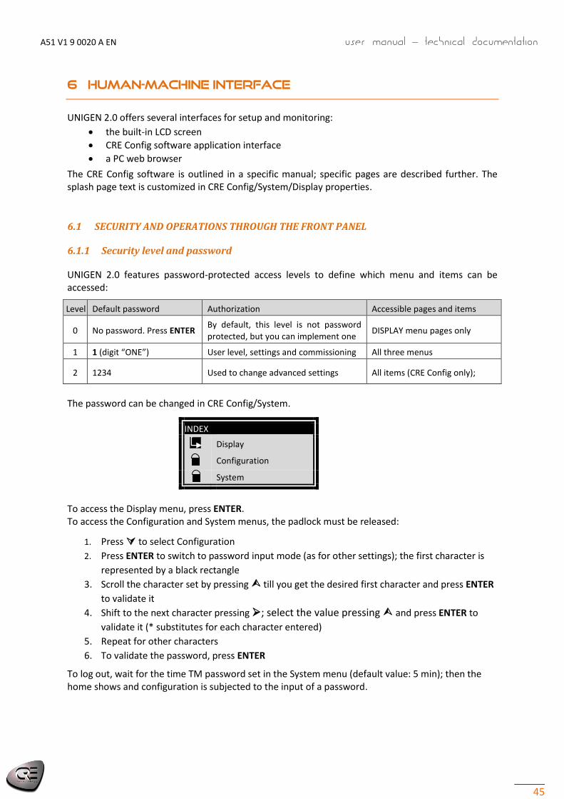
UNIGEN 2.0 features password-protected access levels to define which menu and items can be accessed:
Level Default password Authorization Accessible pages and items
0 No password. Press ENTER By default, this level is not password protected, but you can implement one
DISPLAY menu pages only
1 1 (digit “ONE”) User level, settings and commissioning All three menus
2 1234 Used to change advanced settings All items (CRE Config only);
The password can be changed in CRE Config/System.
INDEX
Display
Configuration
System
To access the Display menu, press ENTER. To access the Configuration and System menus, the padlock must be released:
1. Press to select Configuration
2. Press ENTER to switch to password input mode (as for other settings); the first character is
represented by a black rectangle
3. Scroll the character set by pressing till you get the desired first character and press ENTER
to validate it
4. Shift to the next character pressing ; select the value pressing and press ENTER to
validate it (* substitutes for each character entered)
5. Repeat for other characters
6. To validate the password, press ENTER
To log out, wait for the time TM password set in the System menu (default value: 5 min); then the home shows and configuration is subjected to the input of a password.

User manual – technical documentation A51 V1 9 0020 A EN
46
6.1.2 HMI status
To inhibit some keys or buttons, go to CRE Config/System/Button inhibition. This can also be done through 16-bit word:
Bits numbers:
Inhib.bit 8 7 6 5 4 3 2 1
Key/Button
ESC ENTER SHIFT
6.1.3 Navigation in LCD
Press ESC ENTER and type in the level 1 password as described above to access the top level menu:
INDEX
Display
Configuration
System
A black pointer spots the currently selected item/setting; a white one features other items/settings. Three main menus are available on the LCD screen and the web client monitor:
Display gives information on generator & busbar, & displays real-time information & status
Configuration is used to hone the settings done in CRE Config/Configuration
System is used to change on the fly the settings done in CRE Config/System (Date/Hour, Screen features, ...)
To cycle through the menus and menu items, press or.
To cycle through the pages of lists of settings/readings, press or:
MENU PAGES PARAMETRES
X-1/nPrevious
Next
Setting Label Description
E3557 Button inhibit Each bit inhibit one button/key when set to 1

A51 V1 9 0020 A EN User manual – technical documentation
47
6.1.4 Edition
To change a setting:
1. Navigate to the setting 2. Press ENTER to switch to Edition mode; the current value blinks 3. Pressor to get the new value 4. Press ENTER to validate the new value, ESC to reject it. UNIGEN 2.0 returns to Navigation
mode.
It is also possible via the bus Modbus TCP. See 7.1.
6.2 SUPERVISION
If you keep the PC connected, you can monitor the generator from CRE Config/Scada through UNIGEN 2.0.
An alarm/faults handler is built-in.
Note: In the handler, the buttons are greyed out until the PC is connected to UNIGEN 2.0.

User manual – technical documentation A51 V1 9 0020 A EN
48
6.3 WEB SERVER
The UNIGEN 2.0 web server provides a very easy and efficient way of: loading/downloading configuration file. Downloading alarm/fault/log events Update firmware Visualize alarm/fault
To do so:
1. Connect UNIGEN 2.0 to your PC using an Ethernet direct cable 2. Start a Web browser such as Firefox or Internet Explorer 3. Type in the IP address (factory setting: http://192.168.11.1), or UNIGEN 2.0 hostname 4. When the UNIGEN 2.0 password page appears, enter your password
In the browser, the only soft key is ESC, used to return to the parent menu.

A51 V1 9 0020 A EN User manual – technical documentation
49
6.4 MENU VISUALISATION
L’afficheur LCD permet d’accéder aux informations suivantes :
Power plant
Generator electrical meter
Engine meters
Inputs/Outputs state
About (Only level 0)
A Power plant
A carousel cycles through power plant loads (shared by up to 32 different UNIGEN 2.0 units):
Information available Description
GE 01 … 32 kW active power supplied by each generator:
Percent of nominal of generator
kW
GE 01 … 32 kVAR reactive power supplied by each generator:
Percent of nominal of generator
kVAR
GE 01 … 32 Mode State of each generator
B Generator electrical meter
These pages display in real time all generator electrical measurements in true RMS.
B- 1 Global view
Phase-to-neutral voltage of phase 1
Phase-to-phase voltage of phase pair 3-1
Current of phase 1
Total power: kW, kVAR, cos(ϕ)
B- 2 Frequency (Hz)
B- 3 Phase to neutral (V)
V1, V2, V3
B- 4 Phase to phase (U)
U31, U23, U12
B- 5 Current (A)
I1, I2, I3
B- 6 Active power (kW)
P1, P2, P3
B- 7 Reactive power (kVAR)
Q1, Q2, Q3
B- 8 Total power (kW and kVAR)
B- 9 Power factor
φ1, φ2, φ3 I stands for Inductive, C for Capacitive (signed as per IEC convention)
B- 10 Total power factor
B- 11 Energy meters
kWh and kVARh

User manual – technical documentation A51 V1 9 0020 A EN
50
Notes: The frequency is available if the phase-to-neutral voltage exceeds 15VAC. These pages fit the preset voltage system (see further).
C Engine meters
C- 1
Engine speed (RPM)
Battery voltage
C- 2
Running hours
D Inputs/outputs state
D- 1 Digital inputs 1-5
The name of each input is displayed with its status: active =full dot, inactive = hollow dot.
1 (Raw) is the status of the physical input,
2 (Processed) is the status after conditioning (delay, …).
D- 2 Digital inputs 6-9
Idem.
D- 3 Digital outputs
The name of each output is displayed with its state: active =full dot, inactive = hollow dot.
D- 4 Relay outputs
This menu shows the state of the two relay outputs (Generator breaker).
The name of each output is displayed with its state: active =full dot, inactive = hollow dot.
D- 5 Analog inputs 1-3
The name of each input is displayed with its
Value if really analog
Status if digital: active =full dot, inactive = hollow dot.
E About
These pages show only if you have entered as observer (no password). Otherwise, find it in “System/About“.
1. S/N: serial number, Type (A51V1), Version, Boot version Host name, IP, NM (network mask), GW (gateway). See 2.1.
CRE Config/Scada gives access to readings in addition to the preceding ones. CLOCKS
Reading Label Description Timeout
4450 Loss of speed sensor Time since the speed sensor signal is not available 2203
4465 Speed & voltage stabilization Time generator is waiting to let engine speed & volt stabilize before taking the load (not applicable to static paralleling)
3469
4466 Voltage stabilization Voltage stabilization counter for static paralleling 2056

A51 V1 9 0020 A EN User manual – technical documentation
51
6.5 CONFIGURATION MENU
To access this menu, a password is required; the LCD menu gives access to the following information:
Power plant
Generator
Engine
Protections (Only CRE Config software)
Timers (Only CRE Config software)
kW/kVAR control loops
Modification by variable n° The settings with a purple left border are for CRE Config only.
A Power plant
Power plant applications
Setting Label Value Description
2001 Number of module 1 … 32 Number given to this particular UNIGEN 2.0 on the CAN bus
2000 Total count of modules 1 … 32 Total count of UNIGEN 2.0 units installed on the CAN bus
2050 Paralleling mode Unused [0]
Static [1] Static paralleling: Breakers must be closed manually before the start of the engine and the activation of the digital input “UNIGEN Activation”
2003 Voltage schema Monophase [0] Biphase 180° [1] Triphase 120° [2]
Voltage system selection
B Generator
B- 1 Generator
Setting Label Description
2105 Nominal kW Generator nominal active power
2107 Nominal kVAR Generator nominal reactive power
2102 Nominal voltage Generator nominal voltage
2106 Nominal kW (2) Second nominal power of the generator, activated with logical input
2108 Nominal kVAR (2) Second nominal reactive power of the generator, activated with logical input 2253 Nominal voltage (2) Second nominal voltage of the generator, activated with logical input
2851 Low kW threshold Minimum kW setpoint at the beginning of a ramp up after generator breaker close. KW threshold to open generator breaker during ramp down.
Enter a value above [2412]
2852 High kW threshold Only for mains applications. High threshold of the active power that the generator will not exceed when paralleling with mains.
2853 Load ramp timer Time to ramp up from 0 to 100% of nominal power
2856 Unload ramp timer Time to ramp down from 100 to 0% of nominal power
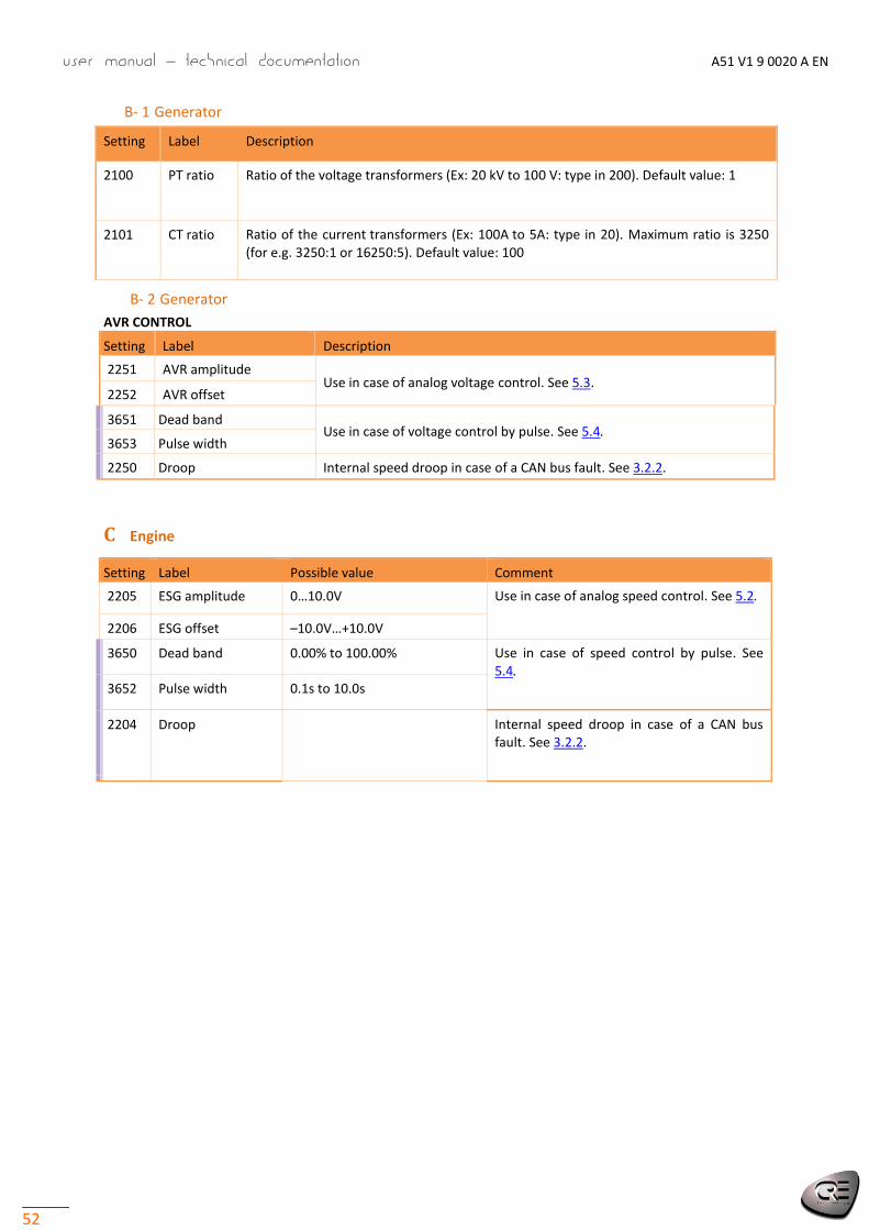
User manual – technical documentation A51 V1 9 0020 A EN
52
B- 1 Generator
Setting Label Description
2100 PT ratio Ratio of the voltage transformers (Ex: 20 kV to 100 V: type in 200). Default value: 1
2101 CT ratio Ratio of the current transformers (Ex: 100A to 5A: type in 20). Maximum ratio is 3250 (for e.g. 3250:1 or 16250:5). Default value: 100
B- 2 Generator
AVR CONTROL
Setting Label Description
2251 AVR amplitude Use in case of analog voltage control. See 5.3.
2252 AVR offset
3651 Dead band Use in case of voltage control by pulse. See 5.4.
3653 Pulse width
2250 Droop Internal speed droop in case of a CAN bus fault. See 3.2.2.
C Engine
Setting Label Possible value Comment
2205 ESG amplitude 0…10.0V Use in case of analog speed control. See 5.2.
2206 ESG offset –10.0V…+10.0V
3650 Dead band 0.00% to 100.00% Use in case of speed control by pulse. See 5.4.
3652 Pulse width 0.1s to 10.0s
2204 Droop Internal speed droop in case of a CAN bus fault. See 3.2.2.

A51 V1 9 0020 A EN User manual – technical documentation
53
D Protections
All protections work with :
A threshold: triggering level of protection
A timer: time before triggering the protection
An action to do when the fault is present
Generator
Protection 1 (level 1) 2 (level 2) Threshold Delay Action Threshold Delay Action
Over frequency 2400 2401 2402 2436 2437 2438
Under frequency 2403 2404 2405 2439 2440 2441
Over voltage 2406 2407 2408 2442 2443 2444
Under voltage 2409 2410 2411 2445 2446 2447
Mini kW 2412 2413 2414 2448 2449 2450
Maxi kW 2415(1)
2416 2417 2451 2452 2453
Reverse kW 2418 2419 2420 2454 2455 2456
Mini kVAR 2421 2422 2423 2457 2458 2459
Maxi kVAR 2424 2425 2426 2460 2461 2462
Reverse kVAR 2427 2428 2429 2463 2464 2465
Over current 2430 2431 2432 2466 2467 2468
Over neutral current 2433 2434 2435 2469 2470 2471
Uneven load sharing
Uneven kW
Uneven kVAR
3708
3711
3709
3712
3710
3713
–
–
–
–
–
–
(1) Must be under the DBR (intermittent) and MCR (Max continuous rating) curves. Refer to Appendix Standards ISO3046.
Protection k c TMS Is Action
See curves in Appendix
Short circuit 2472 2473 2474 2475 2476 2477
Courbe inverse selon standard IEC ; c=0
Default value 0.14 0 0.02 0.01 110 –
Note: Short-circuit protection need to configure the nominal current per one phase (E2103) via CRE Config. This nominal current and the maximum of the measure currents (between the three phases) are used to compute the percent of current that will be compare with the curve.
E Timeouts and delays
Setting Label Description
3469 Stabilisation Time to wait for speed and voltage to get steady
2056 Voltage stabilisation
(Static paralleling)
Time to wait for voltage stabilisation (static paralleling)
2203 TM sensor lost Time after a "sensor lost" security fault will be triggered if no signal is read from speed measurement input
2478 Horn delay Drop-off delay. See 4.1.2.

User manual – technical documentation A51 V1 9 0020 A EN
54
F Control loops
F- 1 kW control
Setting Label Description
2913 P Proportional gain of ramp kW
2917 P Proportional gain of active load sharing
2918 I Integral of active load sharing
FREQUENCY CENTERING
Setting Label Description
2927 (2)
Hz center act Activation of the frequency centering
2926 (1)
Hz center gain Global gain of the frequency centering
(1) Select the menu item Options/Advanced or in level 2 (2) This setting can be modified using TXT file or modification by variable number menu (1 by default)
F- 2 kVAR control
Setting Label Description
2967 P Proportional gain of ramp kVAR
2959 P Proportional gain of reactive load sharing
2960 I Integral of reactive load sharing
VOLTAGE CENTERING
Setting Label Description
2970 (1)
U center act Activation of the voltage centering (1) This setting can be modified using TXT file or modification by variable number menu (1 by default)
G Modification by variable number
This page is very useful when you are familiar with key variable numbers, for example the ones you often modify. Simply enter the variable number, and then enter its value.
Note: You can only change settings 2xxx…3xxx. Some are not accessible in regular menus.
CRE Config EXTRA SETTINGS These settings can still be modified through the LCD (Modification by variable number).

A51 V1 9 0020 A EN User manual – technical documentation
55
POWER MANAGEMENT SYSTEM (LOAD DEPENDENT START/STOP)
Setting Label Possible value Description
2850 Load/Unl. mode
[0] Inhibited
[1] GE number
[2] Hours run
[3] By custom
No automatic start/stop of generators according to aggregate load
Generators start/stop according to the Generator number
Generators start/stop according to the UNIGEN 2.0 running hour meter
Generators start/stop according to my priority number [2863] (1 … 32)
2855 TM before load
Default: 10.0s Delay with power above threshold E2854 before UNIGEN 2.0 requests another generator to start and share load
2854 LV Load thres
Default: 80% Percent of load on the power plant above which another engine is requested to start and share the load
2858 TM before unload
Default: 10.0s Delay before deciding to reduce the count of running generators in load/unload management
2857 LV Unload Default: 20% Percent of load on the power plant under which an engine is stopped. Used when E2859 = 0
2863
Customer priority generator number
See parameter 2850
DIGITAL INPUTS AND OUTPUTS, AND CANopen
See chapters 8.3 and 7.2.
LOGGER
UNIGEN 2.0 can save up to 1350 pieces of data. In addition to Power state, up to 10 readings/statuses can be selected. This includes archived alarms and faults. They are archived on change of value. Format:
jj/mm/aa hh:mn:ss.100ms label XXXX=YYYY . XXXX = parameter number, YYYY = value.
In CRE Config/Configuration/Logger:
Tick the box Log on/off to enable the data logger
Enter the codes in the text area (using the spin is NOT recommended as you have to scroll a lot).
The records can be downloaded from CRE Config or the web site.

User manual – technical documentation A51 V1 9 0020 A EN
56
6.6 SYSTEM MENU
It gives access to the following pages where with readings, or settings to modify:
Date/Time
Screen setup
Ethernet
About (read only)
A Date / Time
“Date / Time” allows you to modify the date and the time:
Label Description
Date Year/Month/Day/Day of week
Time (hh:mm) Time adjustment (H M)
GENERATOR METER SETTING
When UNIGEN 2.0 is not connected to a new generator, set in CRE Config the initial values of energies, count of starts and running hours.
B Screen setup (Display properties and password)
C Ethernet
This page allows to configure the Ethernet connexion with the following parameters:
DHCP
IP address
Network Mask
GateWay IP address
HTTP port
Modbus port
D About
This page displays some information on module and on Ethernet connection.
Serial number (S/N)
Module reference (type)
Software version
Boot software version
Hostname
IP address
Network Mask
GateWay IP address
Setting Label Default Description
3554 Contrast 50% Adjustment of LCD contrast from 0 to 100%
3555 Backlight 100% Adjustment of LCD backlight from 0 to 100% of the max backlight intensity
3552 Backlight saver timeout
5 min Time without navigation (in minutes) after which the backlight turns off.
0 means infinity.
3553 Password timeout
5 min Time without navigation (in minutes) after which password is inactive.
0 means infinity.
3551 Screen saver timeout
5 min Time without navigation (in minutes) after which the display exit menus and show screen saver. 0 means infinity.
– Line 1 to Line 2 CRE Tech its URL
The two lines of text displayed in the Splash screen saver can be modified on the fly. Each line can include up to 21 characters in length
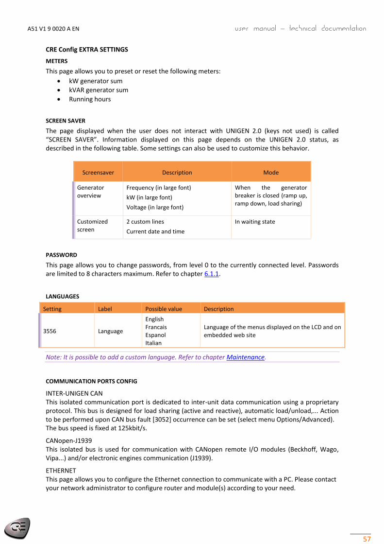
A51 V1 9 0020 A EN User manual – technical documentation
57
CRE Config EXTRA SETTINGS
METERS
This page allows you to preset or reset the following meters:
kW generator sum
kVAR generator sum
Running hours
SCREEN SAVER
The page displayed when the user does not interact with UNIGEN 2.0 (keys not used) is called “SCREEN SAVER”. Information displayed on this page depends on the UNIGEN 2.0 status, as described in the following table. Some settings can also be used to customize this behavior.
Screensaver Description Mode
Generator overview
Frequency (in large font)
kW (in large font)
Voltage (in large font)
When the generator breaker is closed (ramp up, ramp down, load sharing)
Customized screen
2 custom lines
Current date and time
In waiting state
PASSWORD
This page allows you to change passwords, from level 0 to the currently connected level. Passwords are limited to 8 characters maximum. Refer to chapter 6.1.1.
LANGUAGES
Setting Label Possible value Description
3556 Language
English Francais Espanol Italian
Language of the menus displayed on the LCD and on embedded web site
Note: It is possible to add a custom language. Refer to chapter Maintenance.
COMMUNICATION PORTS CONFIG
INTER-UNIGEN CAN This isolated communication port is dedicated to inter-unit data communication using a proprietary protocol. This bus is designed for load sharing (active and reactive), automatic load/unload,... Action to be performed upon CAN bus fault [3052] occurrence can be set (select menu Options/Advanced). The bus speed is fixed at 125kbit/s.
CANopen-J1939 This isolated bus is used for communication with CANopen remote I/O modules (Beckhoff, Wago, Vipa...) and/or electronic engines communication (J1939).
ETHERNET This page allows you to configure the Ethernet connection to communicate with a PC. Please contact your network administrator to configure router and module(s) according to your need.
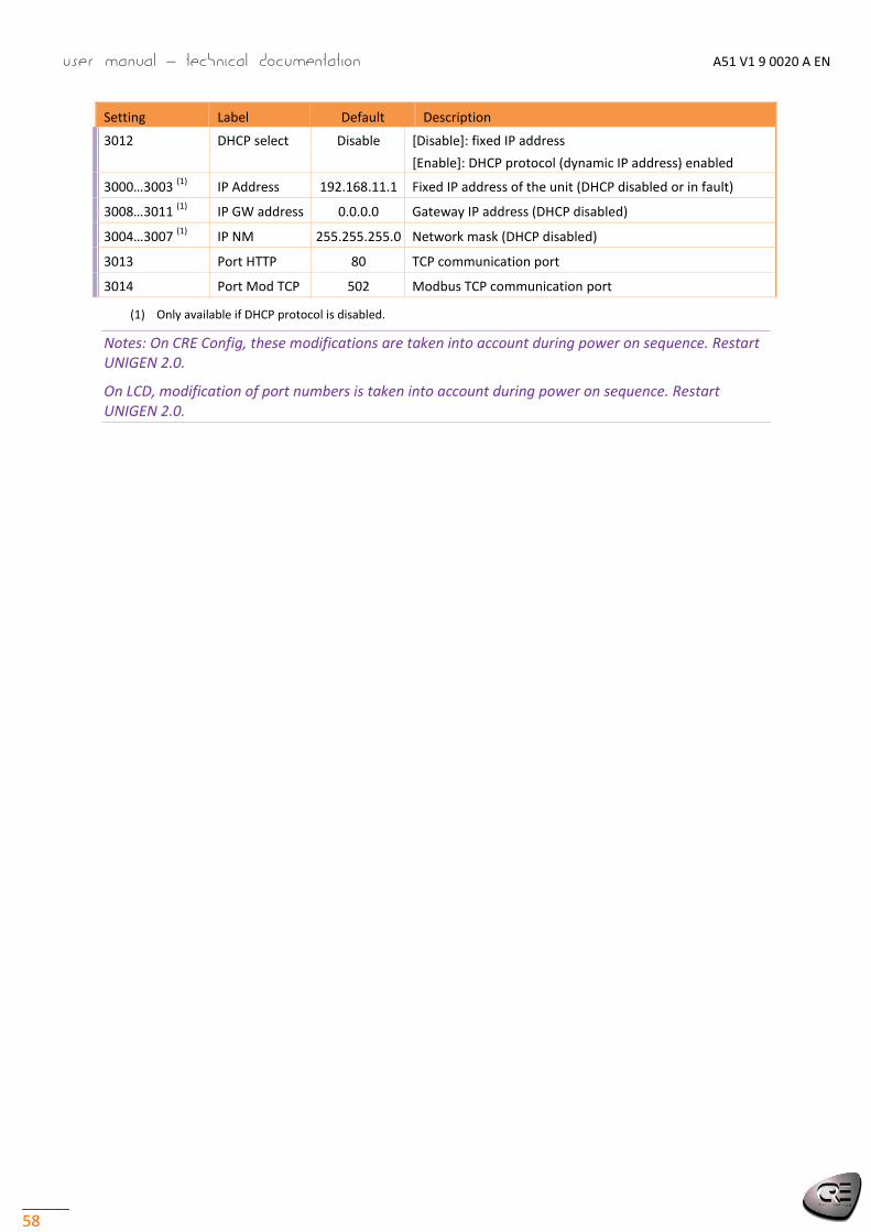
User manual – technical documentation A51 V1 9 0020 A EN
58
Setting Label Default Description
3012 DHCP select Disable [Disable]: fixed IP address
[Enable]: DHCP protocol (dynamic IP address) enabled
3000…3003 (1)
IP Address 192.168.11.1 Fixed IP address of the unit (DHCP disabled or in fault)
3008…3011 (1)
IP GW address 0.0.0.0 Gateway IP address (DHCP disabled)
3004…3007 (1)
IP NM 255.255.255.0 Network mask (DHCP disabled)
3013 Port HTTP 80 TCP communication port
3014 Port Mod TCP 502 Modbus TCP communication port
(1) Only available if DHCP protocol is disabled.
Notes: On CRE Config, these modifications are taken into account during power on sequence. Restart UNIGEN 2.0.
On LCD, modification of port numbers is taken into account during power on sequence. Restart UNIGEN 2.0.

A51 V1 9 0020 A EN User manual – technical documentation
59
6.7 DEDICATED PAGES
The dedicated pages include:
The faults page
The alarms page
The information page.
At any time, you can display the faults/alarms/information on LCD screen by pushing button. If an active fault exist and has not been acknowledged yet, the active fault page will be displayed. Otherwise if an active alarm exist and has not been acknowledged yet, the active alarm page will be displayed. Otherwise the information page will be displayed. You can navigate through these dedicated pages with the high, low, left, right arrows buttons.
To return on previous page, press ESC or button.
6.7.1 Faults and alarms
The latest 15 active faults and alarms show in addition of the latest 30 archive faults and alarms. They are time-stamped as follows: dd/mm/yy hh:mn:ss protec. label On (or Off).
To reset the tripped protections, press “SHIFT+I.
Note: Fix the condition triggering the protection before clearing the alarm; failure to do this will trigger the protection again.
To erase the Faults/Alarms archive, in CRE Config/Display/Faults or Alarms, press Erase button.
Note: Erase button will erase all archives including Faults, Alarms and loggers.
6.7.2 Information
These pages allow displaying the power current state with the associate elapsed time in this state.
In addition, 2 variables per page can be consulted. Power [4001] displays the unit current state regarding power management.
Custom variables: To display any reading, enter its 5-digit code.
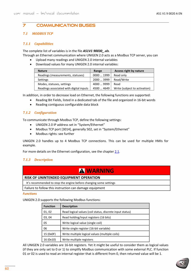
User manual – technical documentation A51 V1 9 0020 A EN
60
7 COMMUNICATION BUSES
7.1 MODBUS TCP
7.1.1 Capabilities
The complete list of variables is in the file A51V1 90030_.xls. Through an Ethernet communication where UNIGEN 2.0 acts as a Modbus TCP server, you can
Upload many readings and UNIGEN 2.0 internal variables
Download values for many UNIGEN 2.0 internal variables:
Nature Range Access right by nature
Readings (measurements, statuses) 0000 … 1999 Read only
Settings 2000 … 3999 Read/Write
Modes, statuses, settings 4000 … 9999 Read
Readings associated with digital inputs 4500 … 4649 Write (subject to activation)
In addition, in order to decrease load on Ethernet, the following functions are supported:
Reading Bit Fields, listed in a dedicated tab of the file and organized in 16-bit words
Reading contiguous configurable data block
7.1.2 Configuration
To communicate through Modbus TCP, define the following settings:
UNIGEN 2.0 IP address set in “System/Ethernet”
Modbus TCP port [3014], generally 502, set in “System/Ethernet”
Modbus rights: see further
UNIGEN 2.0 handles up to 4 Modbus TCP connections. This can be used for multiple HMIs for example.
For more details on the Ethernet configuration, see the chapter 2.1.
7.1.3 Description
WARNING
RISK OF UNINTENDED EQUIPMENT OPERATION
It’s recommended to stop the engine before changing some settings
Failure to follow this instruction can damage equipment
Functions
UNIGEN 2.0 supports the following Modbus functions:
Function Description
01, 02 Read logical values (coil status, discrete input status)
03, 04 Read holding/input registers (16 bits)
05 Write logical value (single coil)
06 Write single register (16-bit variable)
15 (0x0F) Write multiple logical values (multiple coils)
16 (0x10) Write multiple registers
All UNIGEN 2.0 variables are 16-bit registers. Yet it might be useful to consider them as logical values (if they are only set to 0 or 1) to simplify Modbus communication with some external PLC. If function 01 or 02 is used to read an internal register that is different from 0, then returned value will be 1.

A51 V1 9 0020 A EN User manual – technical documentation
61
UNIGEN 2.0 registers start from address 0. Depending on your Modbus TCP client equipment-software, you may need to use an offset of 1 when reading/writing registers as addresses may start from address 1. In this case, request address/register number 1 to access variable 0000 inside UNIGEN 2.0. The 32-bit variables can be written to only with function 0x10.
If a digital input modifies a piece of data also to be written by Modbus, the latest request takes over the other. Data 10000…10299 can be read by block. See further.
Access rights
The access rights depend on the parameter nature and on massive permissions. To grant massive access rights, set to 1 the corresponding bits in the word 3015:
In CRE Config/System/Network configuration/Modbus access rights, just tick a checkbox:
Bit # Label Use
0 Writing to Date/Time Synchronization of UNIGEN 2.0 clock. See chapter A
1 Writing to Engine meters Manual adjustment of counters (see next table). See chapter A
2 Writing to digital input function register
8 Reading using Modbus TCP Opens the possibility to grant reading individual permissions
9 Writing using Modbus TCP Opens the possibility to grant writing individual permissions
The counters, encoded on 32 bits, include:
Counters (MSB|LSB) Label
0080|0079 Generator kWh
0082|0081 Generator kVARh
0084|0083 Engine running hours
Bit Fields
Bit fields are meant for decreasing communication bus load. They pack up to 16 logic variables inside a single register. This way a single Modbus request can be used to read a chunk of information. Each variable contains the current value of 16 logic variables such as breaker positions, faults, alarms…
They are listed out in the Bit fields tab of the document A51V1 90030_.xls. The bit fields 0956 … 0969 have latched values: a reset is required for them to return to 0.
Note: Available data are related only to faults that occurred after the latest power up sequence. Events that occurred before UNIGEN 2.0 has been power cycled are listed in the FAULT pages but NOT among the variables.
Wri
tin
g u
sin
g
Mo
db
us
TCP
Rea
din
g u
sin
g
Mo
db
us
TCP
No
t u
sed
No
t u
sed
No
t u
sed
No
t u
sed
Wri
tin
g to
inp
ut
fun
ctio
n r
egis
ters
No
t u
sed
Wri
tin
g to
En
gin
e
cou
nte
rs
Wri
tin
g to
Dat
e/Ti
me
Bit # 9 8 7 6 5 4 3 2 1 0
Default value 1 1 0 0 0 0 1 0 0 0

User manual – technical documentation A51 V1 9 0020 A EN
62
Custom blocks
To create your own blocks, use the variables 10000 … 10299 in CRE Config/Configuration/Modbus.
There are two ways to configure these blocks:
A. Configuration in CRE Config/Modbus: enter the codes of the variables to read; the readings on the registers 10000 … 10299 will be the pointed values
B. Configuration by an external device; this device must request the following: 1. Write 1 to 3016 to enter into the configuration mode 2. Write the codes to the desired registers (10000 … 10299) 3. Write 0 to 3016 to enter into the read mode
Then to read your own block, you just need to read by Modbus the register 10000 to 10299. Time stamping is done by the master. Example: If the configuration is as follows E10000 = 14; E10001=15; E10002=16, the reading by Modbus of the 3 registers will give to you the hours/minutes/seconds of the UNIGEN 2.0. Later, CRE Config can upload the new configuration if needed.
Modbus communication example
The table below exemplifies a Modbus TCP client sending a reading request (function 04) of 6 registers starting from variable 0079.
Client request UNIGEN 2.0 server response
Field Value Field Value
Function code 04 Function code 04
Starting register (MSB) 00 Data bytes (=2 x count of requested registers) 6
Starting register (LSB) 79 Value of register 0079 (MSB) D0
Count of registers (MSB) 00 Value of register 0079 (LSB) D1
Count of registers (LSB) 06 Value of register 0080 (MSB) D2
Value of register 0080 (LSB) D3
Value of register 0081 (MSB) D4
Value of register 0081 (LSB) D5

A51 V1 9 0020 A EN User manual – technical documentation
63
7.2 CANOPEN EXTENSION MODULES
CANopen extension modules can be used to increase the number of digital inputs and outputs of UNIGEN 2.0. Overall max. count of added inputs: 32 I and 32 O. They are read/written to every 100ms.
7.2.1 Hardware
Each bus coupler is a slave node that supports up to 64 I/O modules that offer different kinds of I/O. Outputs can be by transistors or relays. I/Os can be distributed across up to 4 daisy-chained couplers.
Manufacturer WAGO BECKHOFF VIPA
Bus coupler
750-3xx
BK5150
LC5100 (low cost, no isolation)
VIPA053-1CA00
ID by DIP switch ID by rotary switch ID by DIP switch ID by DIP switch
I/O modules 75x-4xx (inputs)
75x-5xx (outputs)
KLxxxx All the digital I/O terminals are sup-ported except the KL15xx, KL25x2, KL2692 and KL27x1 terminals
VIPA 021-1BF50 (inputs)
VIPA022-1BF00 (outputs)
The modules are stackable and mounted on a DIN-rail. Refer to the extension module’s user manual for correct wiring on the CANopen module side. Check whether the inputs/outputs are protected against short-circuits. If needed, connect the drain to the DIN rail.
Make sure there is a resistor of 120 between CAN H and CAN L on both ends of the cable. For details, refer to the Appendix CAN bus good practices. Available bit-rates: 125/250/500 kbps, 1 Mbps.
Note : CANopen can be used in parallel with J1939 at 250 kbit/s.

User manual – technical documentation A51 V1 9 0020 A EN
64
7.2.2 Configuration
Setting Label Value Description
3151 CANopen config 1
2
3
4
8 inputs + 8 outputs of coupler ID# 1
16 inputs + 16 outputs of coupler ID# 1
32 inputs + 32 outputs of coupler ID# 1
Custom configuration, defined by more settings
3153
3154
3155
CANopen ID# 1
CANopen IN 1
CANopen OUT 1
0 … 255
0 … 32
0 … 32
Identifier of the first coupler
Count of inputs on the first coupler
Count of outputs on the first coupler
3156
3157
3158
CANopen ID# 2
CANopen IN 2
CANopen OUT 2
0 … 255
0 … 32
0 … 32
Identifier of the second coupler
Count of inputs on the second coupler
Count of outputs on the second coupler
3159
3160
3161
CANopen ID# 3
CANopen IN 3
CANopen OUT 3
0 … 255
0 … 32
0 … 32
Identifier of the third coupler
Count of inputs on the third coupler
Count of outputs on the third coupler
3162
3163
3164
CANopen ID# 4
CANopen IN 4
CANopen OUT 4
0 … 255
0 … 32
0 … 32
Identifier of the fourth coupler
Count of inputs on the fourth coupler
Count of outputs on the fourth coupler
The assignment of I/Os is done in the order of couplers and the lower variable number is associated to the lower message number configured. The CANopen inputs and outputs have the same attributes as regular inputs and outputs except the Delay on drop-off of inputs (See chapter 8.3):
Setting Attribute
Digital inputs 1 … 32
3200 … 3231 Function
3232 … 3263 Delay on pick-up
3264 … 3295 Validity
3296 … 3327 Direction
Digital outputs 1 … 32
3350 … 3381 Function
3382 … 3413 Mode (direction):
0: normally de-energized
1: normally energized
On power-up, the configuration is automatically launched. The status 3150 turns to 1. The error time-out (3152) is 10.0s by default.
7.2.3 Mapping
CANopen inputs and outputs are accessed by their code:
Inputs: 0800 … 0831
Outputs: 4751 … 4782

A51 V1 9 0020 A EN User manual – technical documentation
65
7.3 J1939 COMMUNICATION
7.3.1 Overview
J1939 is a CAN protocol used by “electronic” motors, which include an ECU (or ECM, EMS). In the case of UNIGEN 2.0, it allows you to send commands of speed control. Bit rate: 250kbit/s.
To use the J1939 communication:
1. Enter the “Configuration/Engine/J1939“ page 2. In the list, select the manufacturer [3100] 3. Select the ECU type [3101] 4. Connect the engine ECU and the UNIGEN 2.0 J1939 port
The pair manufacturer-ECU determines the following settings:
UNIGEN 2.0 address on the CAN bus
ECU address on the CAN bus
Speed control: through J1939 or by analog output/pulses UNIGEN 2.0 can communicate with a large number of J1939 engines. As the engine list accrues, please contact CRE Technology or your local distributor if your engine is not mentioned in this document. In any case, if your ECU does not belong to the following list, try:
1. To select the generic ECU from your manufacturer
2. To select the GENERIC manufacturer, then modify the UNIGEN 2.0 [3103] and ECU [3102] address according to the ECU documentation (Modification by variable number)
7.3.2 Search engines list
Manufacturer [3100] ECU [3101]
[1] GENERIC [0]
S6 (DC16-45A) [1]
[2]
GENERIC [0]
EMS2 [1]
EDC4 [2]
94xGE [3]
124xGE [4]
1640-2GE [5]
1643GE [6]
D6 [7]
D7 [8]
D13GE-Tier3 [9]
[3] GENERIC [0]
1100 (A4E)
[4]
GENERIC [0]
NEF (EDC) [1]
CURSOR [2]
CURSOR9 (EDC) [3]
CURSOR11 [4] (1)
[6]
GENERIC [0]
QSX15-G8 (CMS570) [1]
CM850 [2]

User manual – technical documentation A51 V1 9 0020 A EN
66
Manufacturer [3100] ECU [3101]
QSB5 (PGI 1.1) [3]
QSB7 (PGI 1.1) [4]
QSL9 (PGI 1.1) [5]
QSM11 (PGI 1.1) [6]
QSX15 (CMS570) [7]
QSK19 (PGI 1.1) [8]
QSK38 (PGI 1.1) [9]
QSK50 (PGI 1.1) [10]
QSK60 (PGI 1.1) [11]
[7] GENERIC [0]
JDEC [1]
[8] GENERIC [0]
ADEM A4E2 (C4.4 & C6.6) [1]
[9] GENERIC [0]
EMR [1]
EMR2 [2]
EMR3 [3]
[10]
Voir Appendice MTU
ECU8 + Smart Connect [3]
(1) Cummins 109G ECU may not support speed control through J1939. ECU with Cummins G Drive firmware should support J1939 speed control

A51 V1 9 0020 A EN User manual – technical documentation
67
8 RESOURCES FOR SETUP & MAINTENANCE
UNIGEN 2.0 handles several files used for setup or maintenance.
The Configuration file allows you to:
Set the value of every setting
Change the units of analog inputs (example: V, mbar, psi, …)
Change the accuracy when displaying analog values (example: 24V or 24.0V)
Change the labels of inputs and the screensaver
The log file contains the history of time-stamped data (alarm/faults, FIFO data as selected in CRE Config/Configuration/Logger). It is used for maintenance.
The action file contains the list of effects of alarm/faults. It is a sub-file of the text file. They are listed out in 4.1.1.
The firmware upgrade is a zip file.
8.1 FILE TRANSFER
These files can be transferred to or from UNIGEN 2.0. Use CRE Config/System/PC transmit-receive OR the web server.
Erase and Reset to factory settings are available in CRE Config (for the latter, select Options/Advanced and connect on level 2).
8.1.1 UNIGEN 2.0 -> PC file transfer
This page allows you to download a file from UNIGEN 2.0 to the PC:
Configuration file
Log file
List of actions on alarms/faults
Note: The file transfer is only possible when the engine is waiting (No synchronization, No load sharing).
Configuration file
To display the current configuration file in an internet browser, select “Configuration file”.
In the web browser, to save this file, right-click in the page with the text file, and select Save as.
CAUTION
To edit a new configuration from the configuration file, it is strongly recommended to use a configuration file compatible with the installed firmware version:
1. Upload the file from UNIGEN 2.0 2. Modify it 3. Download this new configuration file to UNIGEN 2.0
GENSYS
PC
Eras
e
Re
set
to
fact
ory
se
ttin
gs
Tran
sfe
r

User manual – technical documentation A51 V1 9 0020 A EN
68
Log file
Upload the file. In the web browser, to save the file, right-click in the page with the file, and select Save as.
List of actions on alarm/fault
By selecting “Action on alarm/fault”, a file containing all potential alarms/faults and their use is displayed. To save this file, right-click in the page with the text file, and select Save as.
Example:
S/N:4316A1003
Type:A51V1
Version:v0.03
Bootversion:v1.20
Date:06/01/17
Hour:10h30m59s
***** Effet alarme/defaut *****
0 : Disable
1 : Gen electrical fault
3 : Alarm
8 : Droop
(1) -> level 1
(2) -> level 2
Potentiel Alarm./Def. Parametre actuel ANSI C37-2
V00600 CAN1 status <-- V03052 = 8
V00602 CAN2 status <-- V03053 = 0
……
8.1.2 PC -> UNIGEN 2.0 file transfer
This page allows you to send parameters file, or language file. 1. Click the “Browse...” button 2. Select the file to download 3. Click the “Save” button.
When the operation is completed, a screen shows on the PC.
Note: Before edition it is recommended to save the current configuration with the “UNIGEN 2.0 -> PC” page. The file transfer is only possible when the engine is waiting (No synchronization, no load sharing).
8.1.3 Firmware upgrade
This page allows you to upgrade to the latest firmware that can be found on CRE technology Web site. See chapter Maintenance.
8.2 TEXT FILE DESCRIPTION
8.2.1 Variable naming
The file named A51 V1 9 0030x.xls describes each variable. The variable format is VXYYYY.
X relates to the type of variable:
0 and 1: a reading or a real-time value (Voltage phase 1, CAN bus fault …)
2, 3 and 4: a setting to store in non-volatile memory (Generator number, Nominal power …)
YYYY is the code of the variable.

A51 V1 9 0020 A EN User manual – technical documentation
69
The parameters are stored in a non-volatile FLASH memory in the unit. It is possible to download or upload them with a PC, which allows the user to save, modify and reuse them later. All these values are stored in the text file. This chapter describes the layout of the file.
8.2.2 Text file description
The complete unit setup can be contained in a simple text file. This file can be downloaded from UNIGEN 2.0 to be kept on a PC. It can also be manually edited on a PC and sent to UNIGEN 2.0 to fully setup it in a single step. This text file is made up of different blocks:
Parameter values
Label definitions
Text definitions
Unit and accuracy definitions
Parameter definition block
The block start is the PARAMETERS statement. Each setting (2000 … 4000) can be found as an input in this block. The structure of the input is as follows:
The variable parameter number preceded by the letter V (Ex: V02000)
The parameter value (Ex: 2)
The label (optional: only for user information) (Ex: Nb of gen.)
The minimal value (optional: only for user information) (Ex: +00001)
The maximal value (optional: only for user information) (Ex: +00032)
Unit
Example: PARAMETERS
V02000 2 Nb of gen. +00001 +00032
V02001 1 GE number +00001 +00032
It is possible to modify the values directly in the text file before uploading it into UNIGEN 2.0. The user must be sure that the modified value is within the minimum / maximum range of the parameter. Failure to do so leads to an error message during uploading (see chapter 9.3). It is also possible to write to an incomplete parameter block (not all parameters are displayed in the list). When uploaded, such a file modifies only the parameters which have been entered, the others remain unchanged. This procedure can be used to upload an old text file into a newer module or to activate special features independently.
Label definition block
The block start is the LABELS statement. This block is used to define custom labels for CRE Config and the LCD (digital I/Os, analog Is, CANopen I/Os, relay outputs, cycles before maintenance). Each line of this block contains 2 elements:
The variable number of the text, preceded by the letter L for label
The text itself between quotes
LABELS
L01130 Sample label
Labels are 14 characters long. Supported characters include [a...z], [A...Z], [0...9] and the following characters:
<space> ?! # $ ( ) * + / : ; = [ ] ^ _ . - All other characters are NOT recommended, and will be replaced by ? characters.
Note: All custom labels apply to all languages.
Text definition block
The block start is the TEXTS statement. Each line of this block contains 2 elements:
The variable number of the text, preceded by the letter T
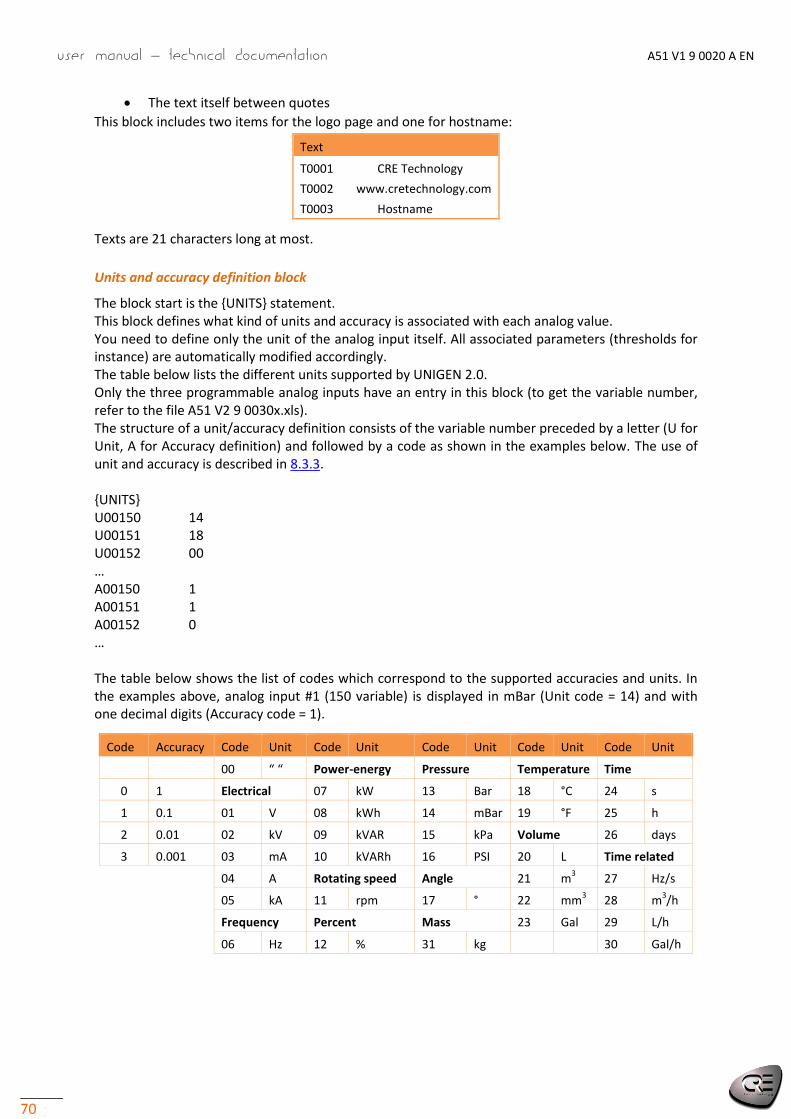
User manual – technical documentation A51 V1 9 0020 A EN
70
The text itself between quotes
This block includes two items for the logo page and one for hostname:
Text
T0001 CRE Technology
T0002 www.cretechnology.com
T0003 Hostname
Texts are 21 characters long at most.
Units and accuracy definition block
The block start is the UNITS statement. This block defines what kind of units and accuracy is associated with each analog value. You need to define only the unit of the analog input itself. All associated parameters (thresholds for instance) are automatically modified accordingly. The table below lists the different units supported by UNIGEN 2.0. Only the three programmable analog inputs have an entry in this block (to get the variable number, refer to the file A51 V2 9 0030x.xls). The structure of a unit/accuracy definition consists of the variable number preceded by a letter (U for Unit, A for Accuracy definition) and followed by a code as shown in the examples below. The use of unit and accuracy is described in 8.3.3. UNITS U00150 14 U00151 18 U00152 00 … A00150 1 A00151 1 A00152 0 … The table below shows the list of codes which correspond to the supported accuracies and units. In the examples above, analog input #1 (150 variable) is displayed in mBar (Unit code = 14) and with one decimal digits (Accuracy code = 1).
Code Accuracy Code Unit Code Unit Code Unit Code Unit Code Unit
00 “ “ Power-energy Pressure Temperature Time
0 1 Electrical 07 kW 13 Bar 18 °C 24 s
1 0.1 01 V 08 kWh 14 mBar 19 °F 25 h
2 0.01 02 kV 09 kVAR 15 kPa Volume 26 days
3 0.001 03 mA 10 kVARh 16 PSI 20 L Time related
04 A Rotating speed Angle 21 m3 27 Hz/s
05 kA 11 rpm 17 ° 22 mm3 28 m
3/h
Frequency Percent Mass 23 Gal 29 L/h
06 Hz 12 % 31 kg 30 Gal/h

A51 V1 9 0020 A EN User manual – technical documentation
71
8.3 I/O LINES
8.3.1 Digital inputs
Each input is tagged with a label defined in CRE Config/Configuration, and features several attributes set in the Configuration menu:
Validity
Direction
Delay
Function
Configurable input label
This is the name you give to the input. The name shows in the info, alarm, and fault screens if programmed accordingly.
Direction
For each input, two options are available:
Num Label Function
0 Norm open Used unless the input is used for protection
1 Norm close Normally closed; must be selected if the input is normally connected to 0V and is opened when active
Delays
For each input, two delays can be defined in 100ms steps between 0 and 6553s.
Summary
Delay on
pick-up
Delay on
drop-off
Raw input
Delay on
pick-up
Delay on
drop-off
Delayed input
Raw input
Delayed input

User manual – technical documentation A51 V1 9 0020 A EN
72
Note: If a digital input changes a piece of data also to be written by Modbus, the latest request takes over the other. If 2 digital inputs are assigned to one function, the latest change is taken into account.
Input functions
ESSENTIAL INPUTS
Function Use/Description Ref. chapter
Not used Must be selected if the input is not connected (default value generally)
Generator breaker feedback
Generator breaker position feedback 4.3
UNIGEN CONTROL
Function Use/Description Ref. chapter
Load request
This digital input (optional) allows you to control the load ramp and the unload ramp. In this way, you can :
- Keep the generator low limit after a synchronization
- Keep the generator low limit after an unload ramp.
3
UNIGEN activation In load dependant start/stop, it allows to indicate which generator must be taken in the election.
3.2.3
FRONT PANEL BUTTONS
Function Use/Description Ref. chapter
Fault reset External reset. Alternative to local fault reset in Fault and Alarm pages
4.2.5
Test leds Activates all LEDs of the module in order to check that the LEDs work
EXTERNAL ALARMS/FAULTS
Function Use/Description Ref. chapter
Generator fault request External protection set a generator fault. 4.1.1
Remote alarm External protection set an alarm on the product ibidem
Stop horn Selective external reset; in addition, an output must be preset to Horn
4.1.2
ALTERNATIVE SELECTIONS
Function Use/Description Ref. chapter
Nominal speed 2 Alternative nominal speed selected
Nominal voltage 2 Alternative nominal voltage selected
Nominal power 2 Alternative nominal power (kW/kVAR) selected
CAN BUS INHIBITION
Function Use/Description Ref. chapter
CAN bus inhibition GEn Order to logically withdraw from CAN bus the UNIGEN 2.0 whose number is n.
3.2.1

A51 V1 9 0020 A EN User manual – technical documentation
73
8.3.2 Digital and relay outputs
Each output is tagged with a label defined in CRE Config/Configuration, and features several attributes set in the Configuration menu:
Direction
Pulse length: 0 means no pulse
Function
Directions
Each output can be:
NE: normally energized; the output is de-energized when its function is activated
ND: normally de-energized; the output is energized when its function is activated
Pulse length
Each digital output can be configured to act as a pulse. The pulses lengths are defined with the parameters E2761 to E2766. Set to 0 in order to have a continuous output (No pulse).
Output functions
ENGINE COMMANDS
Function Description Ref. chapter
Excitation command Static paralleling: energizes the AVR excitation relay 3.5
LEDS STATUS
Function Description Ref. chapter
Faults LED Reflects the led status
Alarm LED idem
Generator LED Reflects the led status
GENERATOR STATUS
Function Description Ref. chapter
Generator ready Activated when generator voltages and frequency are stable
Generator voltage presence
Activated if the generator is started and a voltage is detected
Generator active power flow
Voltage detected and breaker close
Generator stop Activated if generator is at rest
Available in automatic Activated in « Load dependant start/stop» when one generator is

User manual – technical documentation A51 V1 9 0020 A EN
74
available to start (UNIGEN Activation activated)
SPEED/VOLTAGE COMMANDS
Function Description Ref. chapter
Increase speed by pulse Speed regulator requiring +/- contacts 5.4
Decrease speed by pulse
Speed regulator requiring +/- contacts. ibidem
Increase voltage by pulse
Idem speed ibidem
Decrease voltage by pulse
Idem speed ibidem
ALARMS/FAULTS SUMMARY
Function Description Ref. chapter
Generator electrical faults summary
External panel. Trigger: at least one generator-detected “fault” 4.1
Alarms summary External panel. Trigger: at least one generator-detected “alarm” ibidem
Horn
External horn or flashing light. Activated whenever a protection triggers. The output is activated when one or more of summary outputs is activated, and reset on acknowledgment
4.1.2
In addition, most protection activations described in chapter 4.2 can be reported on a digital output. On CRE Config, they are listed by categories as shown below. These outputs are available only if the associate alarm/fault is configured. ENGINE PROTECTION GENERATOR PROTECTION COMMUNICATION FAULTS OTHERS
Function Receiver Ref. chapter
Unused Must be selected if you do not connect the output (default value)
Start request Only « Load dependant start/stop ». This digital input must be connected to start the engine.
3.2.3
Low limit is reached This digital output is set at the end of an unload ramp. It allows to open the breaker automatically with an external product.

A51 V1 9 0020 A EN User manual – technical documentation
75
8.3.3 Analog inputs
In addition to the speed and electrical currents and voltages, three analog inputs are available. They
measure a resistance 0…500. However, they can serve as digital inputs or 20 mA transducer input.
Input
Each input is tagged with a name and preset to a function. It features several attributes preset in CRE Config/Configuration/Inputs/Analog inputs:
Accuracy (number of digits after decimal point) among 1 / 0.1 / 0.01 / 0.001
Unit, among No unit, V, kV, mA, A, kA, Hz, kW, kWh, kVAR, kVARh, rpm, %, Bar, mbar, kPa, psi, °, °C, °F, L, Gal, s, h, days, Hz/s, m3/h, L/h, Gal/h
Calibration, measure value according to resistor value in
Calibration
Calibration is used to estimate a reading from a resistance value by interpolation between 2 wrapping resistance values. Negative values are supported for readings. Enter a table in CRE Config /Configuration/Inputs/Analog inputs/Analog Measure Calibration or in text file. Select the Accuracy, desired grade of details for tweaking and manual entering: 0.001, 0.01, 0.1 or 1.
Enter the limits of reading according to the sensor calibration; generally the lower limit is 0 and the slope is Range/Rating. Calculate and enter the intermediary readings to get a linear distribution.
Protections
The input threshold features several attributes preset in CRE Config/Configuration/Protections/ Analog inputs protection:
Level (LV): limit value in units; it can be a low or high threshold
Delay (TM): time after which the trespassing is confirmed
Validation (CT): protection type to which the signal contributes (3 potential values; see chapter 6.1)
Direction (SS): is it a low (0) or high (1) threshold
Summary
The attributes show in the text file:
Threshold
Level Delay Validation Direction Function
AI 1 level 1 2600 2601 2602 2606 2607
AI 1 level 2 2603 2604 2605
AI 2 level 1 2608 2609 2610 2614 2615
AI 2 level 2 2611 2612 2613
AI 3 level 1 2616 2617 2618 2622 2623
AI 3 level 2 2619 2620 2621
Use of an analog input as a digital input
To mimic a digital input, connect the input to Power– through a switch, and select the function to implement in the list CRE Config/Configuration/Analog inputs/Function. Refer to 8.3.1. Then set the delay, validity and polarity.
CT
LV OUT: past threshold
TM TON
IN
Reset
OUT: protection type C1 18
SS C2C3
H,2L,3

User manual – technical documentation A51 V1 9 0020 A EN
76
Use of an analog input as a transceiver input
To mimic a 20mA input, connect the input with a 39Ω resistor between the analog input and the analog common, and select the function 20mA transceiver in the list CRE Config/Configuration/Analog inputs/Function. The non-linearity of the sensor can be corrected through a curve. Select the tweaking grade – the resolution in actual value – in accordance with the sensor accuracy.

A51 V1 9 0020 A EN User manual – technical documentation
77
9 MAINTENANCE
9.1 UPGRADING THE SOFTWARE
Prerequisite:
1. Upgrading software is done via the Ethernet connection. It’s mandatory to have a PC and to connect on UNIGEN 2.0
2. Stop the generator 3. Save the current configuration as a text file; refer to chapter 8.1.1 Otherwise the default
settings will be enforced (except for the Ethernet settings) 4. Disconnect all the terminals, except the power supply and Ethernet connections.
Start upgrade:
1. Connect to CRE Config/System/PC transmit-receive or to UNIGEN 2.0 web site 2. Select Update firmware and browse the archive (UNIGEN 2.0 version .zip, ex: v1.00.zip) 3. Click on Update button
Alarm/Fault leds blink and state is display on LCD screen 4. Wait until Update firmware successful shows 5. If need, restore the settings from the text file previously save.
Note: During upgrading (about 2 minutes), UNIGEN 2.0 re-start. Wait until you receive the end of upgrade before using UNIGEN 2.0.
9.2 ADDING A CUSTOM HMI LANGUAGE
By default, 4 languages are available: English, French, Spanish, Italian. In addition, two custom languages can be embedded in UNIGEN 2.0. To add your own language, 2 steps are necessary:
1. Translation
Ask for the Excel file to CRE Technology or your own dealer
Fill in the columns for the new language: labels meant for your UNIGEN 2.0 model.
Return the Excel file to CRE Technology or your own dealer that will send you back a .bin file
2. Downloading When you receive the related .bin file, in CRE Config/System/PC transmit-receive, download .bin file via Upload file command. Wait until Download successful shows.
Note: Unless the contrary is expressly stipulated, CRE Technology reserves the right to use your translation for other uses.
9.3 TROUBLESHOOTING
To get a history of alarms-faults, stop the generator, connect to CRE Config/System/PC transmit-receive/Download log file from UNIGEN 2.0, and click Download.
To restore factory settings into CRE Config, navigate to CRE Config/System/PC transmit-receive/Reset factory settings, and click Reset.
Message "Sensor lost" fault on start In “Configuration/Engine/Speed control settings”, check that the speed measurement origin is accurate (Speed measure = Magnetic or Alternator or J1939). If it originates in the alternator, check the voltage presence on terminals Gen L1, L2, L3, N.

User manual – technical documentation A51 V1 9 0020 A EN
78
If it originates in a magnetic pick-up, check that the engine speed increases up to 1500rpm
Message "CAN bus" fault
Check the related connections, including the one of internal resistor (jumper). Refer to the Appendix.
For inter-UNIGEN bus, check the related settings: count of generators, number of each generator.
No J1939 communication Check that the ECU is powered. Check that the configuration correspond to the engine/ECU. Check that the wiring is correct. Refer to the Appendix. Power cycle UNIGEN 2.0 and ECU. Check that the ECU and its settings are consistent with the J1939 standard. Note: Some ECUs do not provide information if the engine is on stop. The engine starts but runs above/below nominal speed. Check the wiring. Check the speed output. Refer to 5.2. No connection with the PC: consider deactivating the firewall.
List of potential error messages when transferring a file to UNIGEN 2.0
Note: … indiquate a variable number, a label number or a text number according the error message. It will help you to locate your error in your configuration file.
ERROR 001: Only when genset is STOP
File transfer between computer and the unit should be done only when all conditions below are met i.e. when engine is stopped.
ERROR 002: Unknown file type
The file type send is unknown. Check the selected file.
ERROR 004: Write data or checksum error
ERROR 008: Update failed. Please restart update.
Write error in flash during update of the software. Restart the update of the software.
ERROR 010: Variable …. doesn't exist.
The parameter doesn’t exist. Check compatibility of the version/type of the module and the configuration file.
ERROR 011: No write right on variable ….
Access to this variable is not allowed. Only parameter can be modified.
ERROR 012: No write right on label ….
Access to this label is not allowed. Check your configuration file.
ERROR 013: Text …. doesn't exist.
Access to this text is not possible because it doesn’t exist. Check compatibility of the version/type of the module and the configuration file.
ERROR 014: No write right on …. unit
Access to this unit is not allowed. Check your configuration file.

A51 V1 9 0020 A EN User manual – technical documentation
79
ERROR 015: Need password 2 to write on …. variable
Actual password is not sufficient to access such configuration/control level.
ERROR 017: Configuration not allowing …. variable value
The actual setting of the module doesn’t allow modifying this parameter with this value. Check your configuration file and the value of the parameter before sending again your configuration file.
ERROR 018: Variable …. out of range
The value of the parameter is out of range. Check your configuration file before sending again.
ERROR 019: Wrong value for …. variable
An unexpected value has been detected on this parameter. Check the value of the parameter before sending again.
Ex: a text character has been detected instead of a number.
ERROR 020: Language file not for UNIGEN 2.0
The language file send doesn’t correspond to a language file for UNIGEN 2.0. Check the selected language file.
ERROR 021: Too much languages already download
The maximum number of language supported by UNIGEN 2.0 has been reached.
ERROR 022: Wrong language file version
The language file version is above to the UNIGEN 2.0 version. Upgrade your UNIGEN 2.0 with the latest version available or catch the language file compatible with your UNIGEN 2.0 version.
ERROR 023: Label …. doesn't exist.
Modifying this label is not allowed. Check the label number before sending again the configuration file.
ERROR 024: Unit …. doesn't exist.
Modifying this unit is not allowed. Check the unit number before sending again the configuration file.
ERROR 025: Wrong accuracy value on …. (0,1,2 or 3)
The value of the accuracy is out of range. The value must be between 0 and 3.
ERROR 026: Wrong unit value on …. (from 0 to xxx)
The value of the unit is out of range. The value must be between 0 and xxx.
ERROR 027: No header in language file
No header or wrong header of the language file. Check the selected language file before send it again.
ERROR 028: No filename found or too long
No filename or filename is too long. The maximum size of a filename is 40 characters. Rename file and send it again.

User manual – technical documentation A51 V1 9 0020 A EN
80
ERROR 029: Wrong accuracy on parameter ….
The value of the modify parameter has not the right accuracy. Check the value of your parameter before sending again you configuration file. Ex: Below, it’s missing the digit a the tenth 5.00 V02205 5.0_ ESG amplitude +000.00 +010.00V
Warnings do not prevent the module to work but inform the user of a potential problem in his configuration file. WARNING 001: Wrong size of label ….
WARNING 002: Wrong character entered in label ….
WARNING 003: Wrong size of text ….
WARNING 004: Wrong character entered in text ….
These advices indicate that entered labels/texts are too long or a character is not supported by module.
Invalid characters will be replaced by “?”. The valid characters are the followings:
0123456789.-
ABCDEFGHIJKLMNOPQRSTUVWXYZ
!#$()*+/:;=[]^_?
abcdefghijklmnopqrstuvwxyz
The maximum size of a label is 14 characters and of a text is 28 characters.
Modify labels/texts according to the rules above.
WARNING 005: Too many errors...
All errors/warnings messages could not be displayed. There are probably other problems in your configuration file. Solve displayed problems and send your configuration file again in order to display the additional error/warning messages.
WARNING 006: No unit specify on unit ….
WARNING 007: No value specify on parameter ….
WARNING 008: No text specify on text ….
WARNING 009: No label specify on label ….
These warnings indicate that no value has been indicated inside the configuration file for an unit/parameter/text or label. The values will stay unchanged.
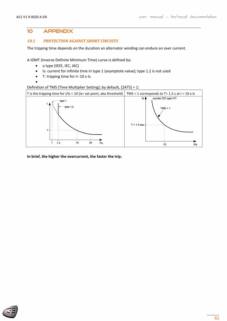
A51 V1 9 0020 A EN User manual – technical documentation
81
10 APPENDIX
10.1 PROTECTION AGAINST SHORT CIRCUITS
The tripping time depends on the duration an alternator winding can endure an over current.
A IDMT (Inverse Definite Minimum Time) curve is defined by:
a type (IEEE, IEC, IAC)
Is: current for infinite time in type 1 (asymptote value); type 1.2 is not used
T: tripping time for I= 10 x Is.
Definition of TMS (Time Multiplier Setting); by default, [2475] = 1:
T is the tripping time for I/Is = 10 (Is= set point, aka threshold) TMS = 1 corresponds to T= 1.5 s at I = 10 x Is
In brief, the higher the overcurrent, the faster the trip.
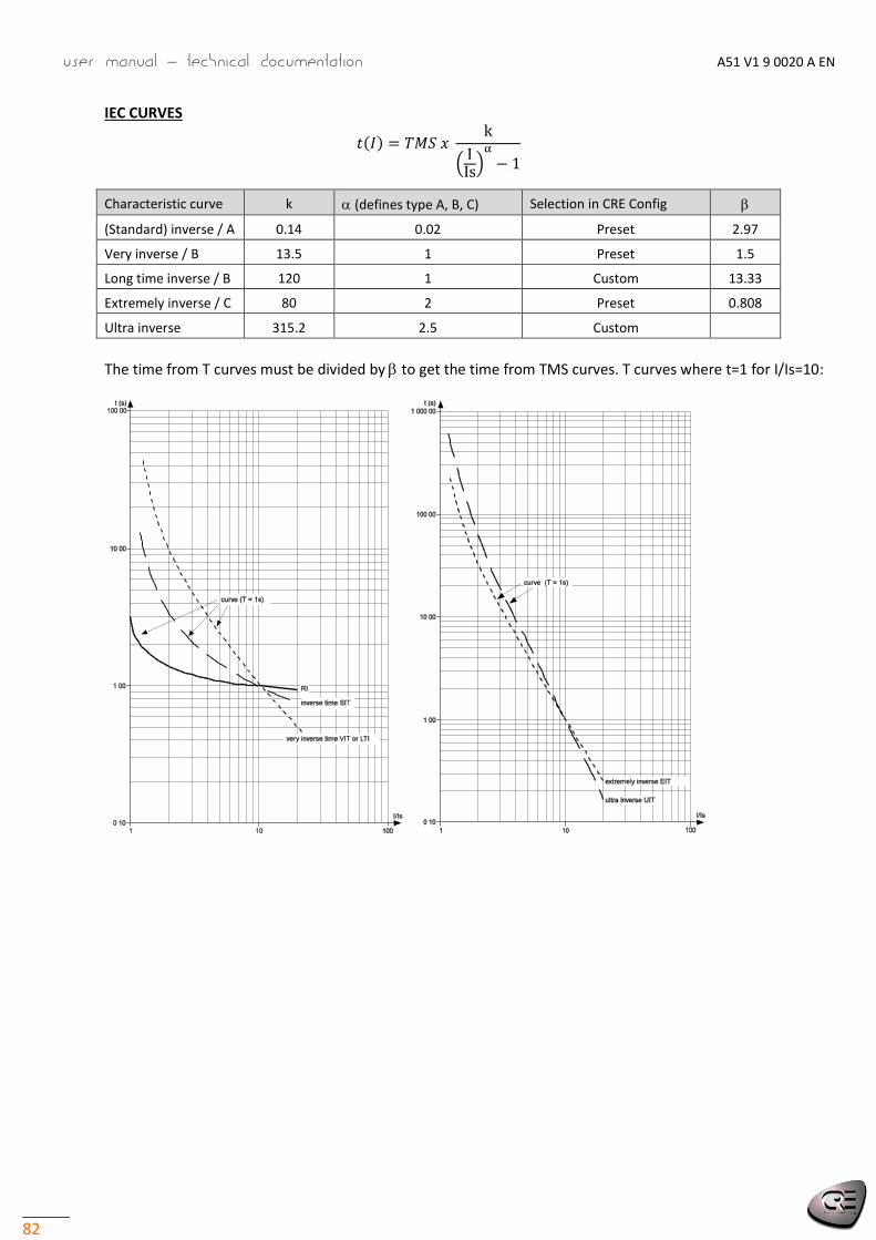
User manual – technical documentation A51 V1 9 0020 A EN
82
IEC CURVES
( )
Characteristic curve k (defines type A, B, C) Selection in CRE Config
(Standard) inverse / A 0.14 0.02 Preset 2.97
Very inverse / B 13.5 1 Preset 1.5
Long time inverse / B 120 1 Custom 13.33
Extremely inverse / C 80 2 Preset 0.808
Ultra inverse 315.2 2.5 Custom
The time from T curves must be divided by to get the time from TMS curves. T curves where t=1 for I/Is=10:

A51 V1 9 0020 A EN User manual – technical documentation
83
Inverse curves just above the pick-up value (not logarithmic abscissae I/Is) for various value of TMS:
TMS:
1 0.9 0.8 0.7 0.6 0.5 0.4
0.3
0.2
0.1
100 s
10 s
1 s
0.1 s

User manual – technical documentation A51 V1 9 0020 A EN
84
IEEE CURVES
( )
Characteristic curve k c
Moderately inverse 0.515 0.1140 0.02
Very inverse 19.61 0.491 2
Extremely inverse 28.2 0.1217 2

A51 V1 9 0020 A EN User manual – technical documentation
85
HOW TO DERIVE CURVES BY PARALLELISM
Say a curve is known. We know tsA (s stands for the start curve) for IA/Is (s stands for set point).
Two curves with same k, and c are parallel: K= tsA/Ts10 = tA/T. This can be used to find tA.
In the preceding curves in logarithmic plot, Ts10=1. For a given I/Is (first column of next table), find K in the row. Then ta = K x T.
1) Only valid for IEC curves
1) means Only valid for IEC curves
I/Is SIT IEC/A VIT, LTI IEC/B
EIT IEC/C
UIT RI not av.
IEEE MI IEC/D
IEEE VI IEC/E
IEEE EI IEC/F

User manual – technical documentation A51 V1 9 0020 A EN
86
10.2 MTU J1939 COMMUNICATION
ECU 8
Smart Connect is used to:
select the speed set point source through a 3-bit code,
set the frequency and speed droop
Through the K1 connection box, the bus connects ECU8, Smart Connect and UNIGEN 2.0: one bus between ECU8 and Smart Connect, one bus between Smart Connect and UNIGEN 2.0. X4 is the Smart Connect J1939 CAN port.
UNIGEN 2.0

A51 V1 9 0020 A EN User manual – technical documentation
87
10.3 CAN BUS GOOD PRACTICES
This chapter describes rules to be used to ensure reliable CAN communication. These rules must be applied to all CAN communications, including inter-UNIGEN CAN bus and ECU/remote I/O CAN bus. In an EMI environment, use a shielded cable to connect CAN bus. The table below lists the standard CAN wiring :
Terminal Standard CAN Mandatory 1 Reserved 2 CAN-L X 3 CAN GND X 4 Reserved 5 CAN SHLD (optional) 6 GND (optional) 7 CAN-H X 8 Reserved 9 CAN V+ (optional)
SHIELD X
CABLES
WARNING
RISK OF EQUIPMENT DAMAGE Switch off the unit before plugging or unplugging the CAN bus connector or disconnecting the wires
Failure to follow this instruction can damage the CAN transmitter/receiver
Cables used must be selected to respond to CAN bus specificities. Always use shielded twisted wire pairs. Deploy the CAN bus in a bus (no mesh, ring or star topology) as shown below:
Bus Mesh Ring Star
Both ends of the CAN bus must be terminated with a 120Ω resistor. The next figure gives the example of three units connected through a CAN bus. Do NOT install any resistor in the middle unit and connect the incoming wire and the outgoing wire on the same terminal (max 1.5 mm² or AWG16; use preferably the same section for both).
terminal terminal terminal
120
Ω
L
L
L
120
Ω
H H H RES RES RES
GND GND GND
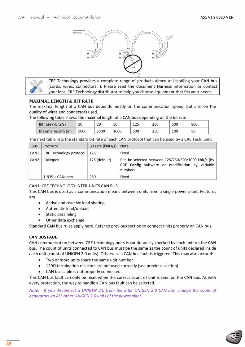
User manual – technical documentation A51 V1 9 0020 A EN
88
CRE Technology provides a complete range of products aimed at installing your CAN bus (cords, wires, connectors…). Please read the document Harness information or contact your local CRE Technology distributor to help you choose equipment that fits your needs.
MAXIMAL LENGTH & BIT RATE The maximal length of a CAN bus depends mostly on the communication speed, but also on the quality of wires and connectors used. The following table shows the maximal length of a CAN bus depending on the bit rate.
Bit rate (kbits/s) 10 20 50 125 250 500 800
Maximal length (m) 5000 2500 1000 500 250 100 50
The next table lists the standard bit rate of each CAN protocol that can be used by a CRE Tech. unit:
Bus Protocol Bit rate (kbits/s) Note
CAN1 CRE Technology protocol 125 Fixed
CAN2 CANopen 125 (default) Can be selected between 125/250/500/1000 kbit/s (By CRE Config software or modification by variable number)
J1939 + CANopen 250 Fixed
CAN1: CRE TECHNOLOGY INTER-UNITS CAN BUS This CAN bus is used as a communication means between units from a single power plant. Features are:
Active and reactive load sharing
Automatic load/unload
Static paralleling
Other data exchange
Standard CAN bus rules apply here. Refer to previous section to connect units properly on CAN bus. CAN BUS FAULT CAN communication between CRE technology units is continuously checked by each unit on the CAN bus. The count of units connected to CAN bus must be the same as the count of units declared inside each unit (count of UNIGEN 2.0 units). Otherwise a CAN bus fault is triggered. This may also occur if:
Two or more units share the same unit number
120Ω termination resistors are not used correctly (see previous section)
CAN bus cable is not properly connected.
This CAN bus fault can only be reset when the correct count of unit is seen on the CAN bus. As with every protection, the way to handle a CAN bus fault can be selected.
Note: If you disconnect a UNIGEN 2.0 from the inter UNIGEN 2.0 CAN bus, change the count of generators on ALL other UNIGEN 2.0 units of the power plant.

A51 V1 9 0020 A EN User manual – technical documentation
89
10.4 CONTROL LOOP TUNING
Each control is carried out by two actions: Proportional and Integral.
P adjusts the rise time (time needed for the system to reach its set point for the first time). Using only the P factor always leaves a static error between the set point and the actual value.
I reduces the deviation between the set point and the actual value.
By increasing P or I, the rise time decreases. However, the overshoot increases and may also make the system unstable (P: fast hunting, I: slow hunting).
G is a sensitivity adjustment for the other settings.
Empirical tuning: A. First set G to 50% B. Set the parameters P, and I to 0 C. Increase the value of P until the system becomes unstable. From this position, decrease the
value of P to 60% of the previous value D. If the system is unstable, decrease G; if it is too slow, increase G.
P
I
Measurement
Set point +
–
G: global gain P: proportional gain I: integral gain
G Command +

User manual – technical documentation A51 V1 9 0020 A EN
90
10.5 POTENTIELS ALARMS-FAULTS TABLE
Download the list from CRE Config/System/PC transmit-receive/Actions on alarm-fault, and tick the boxes to show how the alarms/faults contribute to severity indication and, if any, summary outputs (grey shade prompts usual choice):
1: Generator electrical Fault 3: Alarm Notes :
1) CAN bus inter-UNIGEN faults are not shown. 2) H = level 1, HH = level2
H
HH
L LL
L LL
H
HH
L LL
H
HH
H
HH
H
HH
H
HH
H
HH
H
HH
H
HH
cou
rbe
L LL
H
HH
Gen
erat
or
Ove
rfre
qu
ency
(8
1H
)
Gen
erat
or
Un
der
freq
uen
cy (
81
L)
Gen
erat
or
Un
der
volt
age
(27
)
Gen
erat
or
Ove
rvo
ltag
e (
59
)
Min
kV
AR
(3
7Q
)
Max
kV
AR
(3
2Q
)
–kW
(3
2R
P)
–kV
AR
(3
2R
Q)
Min
kW
(3
7P
)
Max
kW
(3
2P
)
Max
I (5
1)
Max
In (
64
G)
Sho
rt c
ircu
it (
51
) P
has
e m
easu
re
Un
even
kW
U
nev
en k
VA
R
Min
bat
tery
vo
ltag
e
Max
bat
tery
vo
ltag
e
1 3

A51 V1 9 0020 A EN User manual – technical documentation
91
CRE TECHNOLOGY
130 allée Charles-Victor Naudin
Zone des Templiers
Sophia-Antipolis
06410 BIOT
FRANCE
Phone: +33 (0)4 92 38 86 82
Fax: +33 (0)4 92 38 86 83
Website: http://www.cretechnology.com
Email: [email protected]
Technical support: +33 (0)4 92 38 86 86 (office hours: 8.30AM - 12AM / 2PM - 6PM GMT +1)
Email: [email protected]
SKYPE: support-cretechnology.com (voice only)
A worldwide coverage:
Check our entire distributors list around the world on our Web site http://www.cretechnology.com.
Head office: FRANCE
Distributors
Agents

User manual – technical documentation A51 V1 9 0020 A EN
92
www.cretechnology.com CRE TECHNOLOGY has provided the engine and generator industry for over 25 years with standard products and dedicated solutions for engine control, generator protection and paralleling.
All application fields where power is the core resource of performance are covered by CRE TECHNOLOGY. The company is a reference in the industrial, marine and defense businesses.
Our very strong situation allows us to invest, feeding our ambition to be always more advanced, always closer to you. The coming years will see the broadening of our distribution network and of our innovative products portfolio.
BECOME A CRE TECHNOLOGY DISTRIBUTOR
YOUR ACCOUNT & YOUR PRICES
By creating your account, you’ll have access to all your personal data. All the prices of the new CRE TECHNOLOGY website correspond to your business rates.
GET INFORMATION THE WAY YOU WANT IT Fill your cart by choosing the products you want and get all the information you need.
EVERYWHERE WITH YOU
The new CRE TECHNOLOGY website is designed to be responsive to smartphones and touch tablets.
It allows you to consult the documents related to the CRE TECHNOLOGY’s ranges of products.