Uniform Standard for Wood Pallets 2014 (FINAL) - … Wooden Pallet and Container Association 1421...
72
UNIFORM STANDARD FOR WOOD PALLETS National Wooden Pallet and Container Association 1421 Prince, Suite 340 Alexandria, VA 22314-2805 Phone: 703/519-6104 FAX: 703/519-4720 Website: www.palletcentral.com
Transcript of Uniform Standard for Wood Pallets 2014 (FINAL) - … Wooden Pallet and Container Association 1421...
UNIFORM STANDARD
FOR
WOOD PALLETS
National Wooden Pallet and Container Association 1421 Prince, Suite 340 Alexandria, VA 22314-2805 Phone: 703/519-6104 FAX: 703/519-4720 Website: www.palletcentral.com
ii
Copyright © 2014 by the National Wooden Pallet and Container Association
All rights reserved. No part of this standard may be reproduced or transmitted in any form or by any means, electronic or mechanical, including photocopying, recording, or by an information storage and retrieval system, without permission in writing from the
National Wooden Pallet and Container Association.
National Wooden Pallet and Container Association 1421 Prince Street
Suite 340 Alexandria, VA 22314-2805
USA www.palletcentral.com
703-519-6104 tel 703-519-4720 fax
Printed in the United States of America
Wood pallets are manufactured, recycled, repaired or remanufactured for the sole purpose of storing and/or transporting material. Under no circumstances should a pallet be used for anything other than its intended purpose, such as a person standing, stepping, or leaning upon them or otherwise using them for support or as a structural construction component. The wood pallet user has the obligation and responsibility to inspect for damage prior to each pallet use and to determine that the pallet design is appropriate for that particular unit load application. All pallets should be removed from service if determined to be unsafe and dangerous to persons or goods.
iii
DISCLAIMER
This standard was approved by NWPCA on October 2014. It was developed with the sole intent of offering information to parties engaged in the manufacture, recycling, marketing, purchase, or use of pallets for unit loads. This standard is advisory only and acceptance is voluntary and the standard should be regarded as a guide that the user may or may not choose to adopt, modify, or reject. The information does not constitute a comprehensive safety program and should not be relied upon as such. Such a program should be developed and an independent safety adviser consulted to do so.
NWPCA Standards Committee and its staff and members assume no responsibility and disclaim all liability of any kind, however arising, as a result of acceptance or use or alleged use of this standard. User specifically understands and agrees that NWPCA, Standards Committee and its staff and members shall not be liable under any legal theory of any kind for any action or failure to act with respect to the design, installation, manufacture, preparation for sale, sale, characteristics, features, or delivery of anything covered by this standard. Any use of this information must be determined by the user to be in accordance with applicable federal, state, and local laws and regulations.
NWPCA, the Standards Committee and its staff and members make no warranties of any kind, express, implied, or statutory, in connection with the information in this standard. NWPCA and the Standards Committee specifically disclaim all implied warranties of merchantability or of fitness for particular purpose.
By referring to or otherwise employing this standard, the user agrees to defend, protect, indemnify, and hold NWPCA, the Standards Committee, their staff and members harmless from and against all claims, losses, expenses, damages, and liabilities, direct, incidental, or consequential, arising from acceptance or use or alleged use of this standard, including loss of profits and reasonable attorneys' fees which may arise out of the acceptance or use or alleged use of this standard. The intent of this provision and of the user is to absolve and protect NWPCA, the Standards Committee, their staff and members from any and all loss relating in any way to this standard, including those resulting from the user's own negligence.
4
NATIONAL WOODEN PALLET AND CONTAINER ASSOCIATION STANDARDS COMMITTEE
2014
(The following is the roster of the Committee at the time of approval of this version.)
Members Jordan Piland (Chair), Atlas Pallets
Gunilla Beyer, Swedish Forest Industries Federation
James Bisha, Ongweoweh Corporation
LeRoi Cochran, IFCO Systems, N.A. Inc.
Ian Carter, Crane Point Industrial, LLC
John Conway, Conway & Robinson, LLC
Jeffrey Goettel, Superior Pallets, Inc.
Stan Joray, Ox Box
Niels Jorgensen, Kiln-direct.com Daniel Konz, Konz Wood Products
Michael Krisher, Midland Wood Products, Inc.
Al Longman, Pallet Central Enterprises
Matt McGowan, Timber Products Inspection
Mark Oletti, Mid Continent Steel and Wire, Inc.
Greg Ramsey, Philpac Corp.
Ralph Rupert, Millwood Incorporated
Bill Schneider, Remmey - The Pallet Company
Gary Sharon, Litco International, Inc.
Kelso Sims, Southern Fastening Systems
Danny Sparrow, Neal’s Pallet Company
Ryan Stearns, Atlas Pallet Company
Adam Willert, Southwest Pallet, Inc.
Staff Liaison Brad Gething, PhD
5
CONTENTS
. 1 PURPOSE ............................................................................................................... 1 2 SCOPE ................................................................................................................... 1
PART I PRESCRIPTIVE STANDARD 3 TERMINOLOGY AND DEFINITION ........................................................................ 2 4 CLASSIFICATIONS ................................................................................................ 3
4.1 Classes ............................................................................................................ 3 4.2 Use Categories ................................................................................................ 3 4.3 Entry Types ...................................................................................................... 5 4.4 Styles ............................................................................................................... 5 4.5 Top Deck Constructions ................................................................................... 5 4.6 Bottom Deck Constructions .............................................................................. 5 4.7 Sizes ................................................................................................................ 5
5 MATERIALS ............................................................................................................ 7 5.1 Lumber Components ........................................................................................ 7 5.2 Wood Panel (Plywood or OSB) Components ................................................. 10 5.3 Wood-based Composites Components .......................................................... 12 5.4 Engineered Wood Components ..................................................................... 13 5.5 Fasteners ....................................................................................................... 14
6 MANUFACTURE OF PALLETS ............................................................................ 17 6.1 Component Defects ....................................................................................... 17 6.2 Assembly ....................................................................................................... 17
7 REPAIR OF PALLETS .......................................................................................... 21 7.1 Damages ........................................................................................................ 21 7.2 Recommended General Repair Procedures .................................................. 28 7.3 Repair Component Quality ............................................................................. 33 7.4 Repair Workmanship ...................................................................................... 35 7.5 Classes of Repaired 48x40 Notched Three Stringer Pallets .......................... 35 7.6 Additional Descriptions for Class of Repaired Pallets .................................... 35 7.7 Marking .......................................................................................................... 36
8 REMANUFACTURE OF PALLETS ....................................................................... 36 8.1 Quality of Parts .............................................................................................. 36 8.2 Quality of Assembly ....................................................................................... 37
6
PART II PERFORMANCE STANDARD 9 CONDITIONS OF PALLET USE ............................................................................ 39
9.1 Load Condition ................................................................................................ 39 9.2 Support Conditions ......................................................................................... 39
10 MEASURES OF PALLET PERFORMANCE ...................................................... 39 11 TEST PROCEDURES ........................................................................................ 40
11.1 Testing for Physical Models or Prototypes ...................................................... 40 11.2 Testing of Computer Models ........................................................................... 40
PART III PHYTOSANITATION STANDARD 12 PHYTOSANITATION OF WOOD PALLETS ....................................................... 41
12.1 Debarked ........................................................................................................ 41 12.2 Heat treated (HT) Wood Pallets ...................................................................... 41 12.3 Methyl bromide (MB) Fumigated Pallets ......................................................... 41 12.4 New Pallets ..................................................................................................... 41 12.5 Recycled Pallets ............................................................................................. 42
ANNEX A ...................................................................................................................... 43 ANNEX B ...................................................................................................................... 49 ANNEX C ...................................................................................................................... 52 ANNEX D ...................................................................................................................... 53 ANNEX E ...................................................................................................................... 54 ANNEX F ....................................................................................................................... 58 ANNEX G ...................................................................................................................... 64
National Wooden Pallet and Container Association Uniform Standard for Wood Pallets-2014
1
1 PURPOSE
The purpose of this Uniform Standard for Wood Pallets (hereinafter referred to as the Standard)
is to establish nationally recognized minimum quality requirements for the principal types of
wood pallets, and to provide a basis for common understanding among manufacturers, recyclers,
distributors, and users of wood pallets.
2 SCOPE
This Standard applies to all lumber-deck and panel-deck pallets, either new, repaired or
remanufactured as well as their lumber, panels, wood-based composites and engineered wood
components and fasteners. Criteria contained in this Standard are applicable only at the
completion of manufacture.
This Standard is in three parts. Part I is the Prescriptive Standard which concerns the
manufacture of the pallet. This includes pallet and pallet component descriptions, definitions,
fastener descriptions, workmanship criteria, dimensional tolerances, markings, moisture content
levels, and repair and remanufacture of pallets. Part II is the Performance Standard which
concerns the functionality of the pallet. This contains references to the testing of physical
models or prototypes, and computer software to assist manufacturers, recyclers, distributors, and
users to determine the performance level of a specified pallet. Use of the Performance Standard
is required for new, repaired and remanufactured pallet constructions, along with conformance to
Part I of the Prescriptive Standard. Part III covers Phytosanitation of Wood Pallets.
This Standard does not describe other established special requirements for export pallets and
does not address the safety problems, if any, associated with the use of wood pallets. It is the
responsibility of the user of this Standard to establish appropriate safety and health practices and
determine the applicability of regulatory limitations prior to its use.
To assist the user of this Standard, other related standards are listed in ANNEX A.
In any dispute regarding dimensions of components or defects, the U.S. customary units are
governing.
National Wooden Pallet and Container Association Uniform Standard for Wood Pallets-2014
2
PART I PRESCRIPTIVE STANDARD
3 TERMINOLOGY AND DEFINITION1
block - rectangular, square, multisided, or cylindrical deck spacer, often identified by its location
within the pallet as corner block, end block, edge block, inner block, or center or middle block.
block size - pallet member dimension, specified by width followed by height and length.
deckboard - element or component of pallet top and bottom, perpendicular to stringers or
stringerboards.
deckboard size - specified by thickness followed by width and length.
delamination - a visible separation in the plane of a panel or panel component. This may occur
in the panel manufacturing process, or in use due to rough handling. The latter may be caused by
impacting panel edges with a tine tip, and may or may not result in material being removed from
the panel component (see Figure 13).
MIBANT Angle2 - fastener bend angle providing indication of (fastener) toughness and bending
resistance (see Table 3).
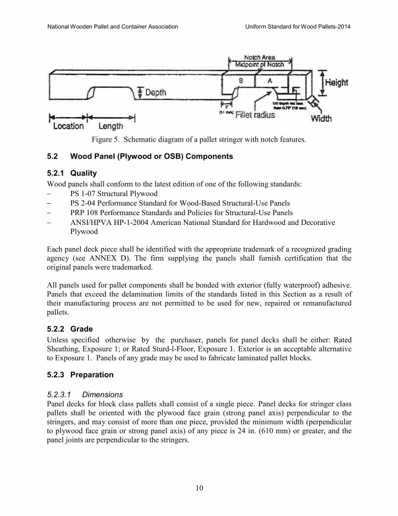
notch area - a region around stringer notches with special defect limitations (see Figure 5).
Pallet Design System© (PDS) - a reliability-based computer-aided design (CAD) software for
wood stringer and block pallets (see Section 11.2).
pallet length - pallet dimension between the extreme pallet ends, parallel to the stringers or top
stringerboards. For panel-deck block pallets without stringerboards, it is the top deck pallet
dimension parallel to the face grain for plywood (strong panel axis).
pallet width - pallet dimension between the extreme pallet sides, parallel to and corresponding to
the length of the top deckboards. For panel deck block pallets without stringerboards, it is the
top deck panel dimension perpendicular to the face grain for plywood (strong panel axis).
pallet size - pallet dimension specified by stringer or stringerboard length, followed by top
deckboard length and overall pallet height. For panel deck block pallets, it is the length, width,
and overall pallet height.
panel - a wood based structural panel, either plywood or oriented strand board (OSB).
1 For a complete listing of pallet definitions, see "Part 1 Definitions and Terminology Covering Pallets and Related
Structures," MH1 Pallets, Slip sheets, and Other Bases for Unit Loads, Material Handling Industry of America
(MHIA), www.mhia.org
2 MIBANT angles are measured according to procedures contained in ASTM F680 Standard Test Methods for Nails,
ASTM International, www.astm.org
National Wooden Pallet and Container Association Uniform Standard for Wood Pallets-2014
3
recycled pallet – pallet made reusable by sorting, repairing or remanufacturing, using new or
reclaimed components from damaged pallets.
recycled wood pallet part - a pallet part that has been removed from a wood pallet after it has
been in service.
remanufactured pallet - a pallet assembled entirely or in part with recycled wood pallet parts and
manufactured by complete reassembly of all parts with new fasteners.
remanufactured combination "combo" pallet - a pallet assembled, specifically, with both new
and recycled wood parts. Combo pallets are typically assembled with recycled top and bottom
deckboards and new wood stringers.
repaired pallet – a pallet with damaged components replaced with new or used components.
shiner - protruding fastener point.
stringer - continuous, longitudinal, solid, built up, or notched beam component of pallet,
supporting and spacing deck components, often identified by its location as edge (side) or
interior (center) stringer.
stringer size - specified by width followed by height and length.
stringerboard - continuous, solid member extending the full length of the pallet, perpendicular to
deckboard members and placed between deckboards and blocks.
stringerboard size - pallet and member dimensions, specified by thickness followed by width and
length.
unit load – assembly of goods or single item on pallet for handling, moving, storing, and
stacking, as single entity
4 CLASSIFICATIONS
4.1 Classes
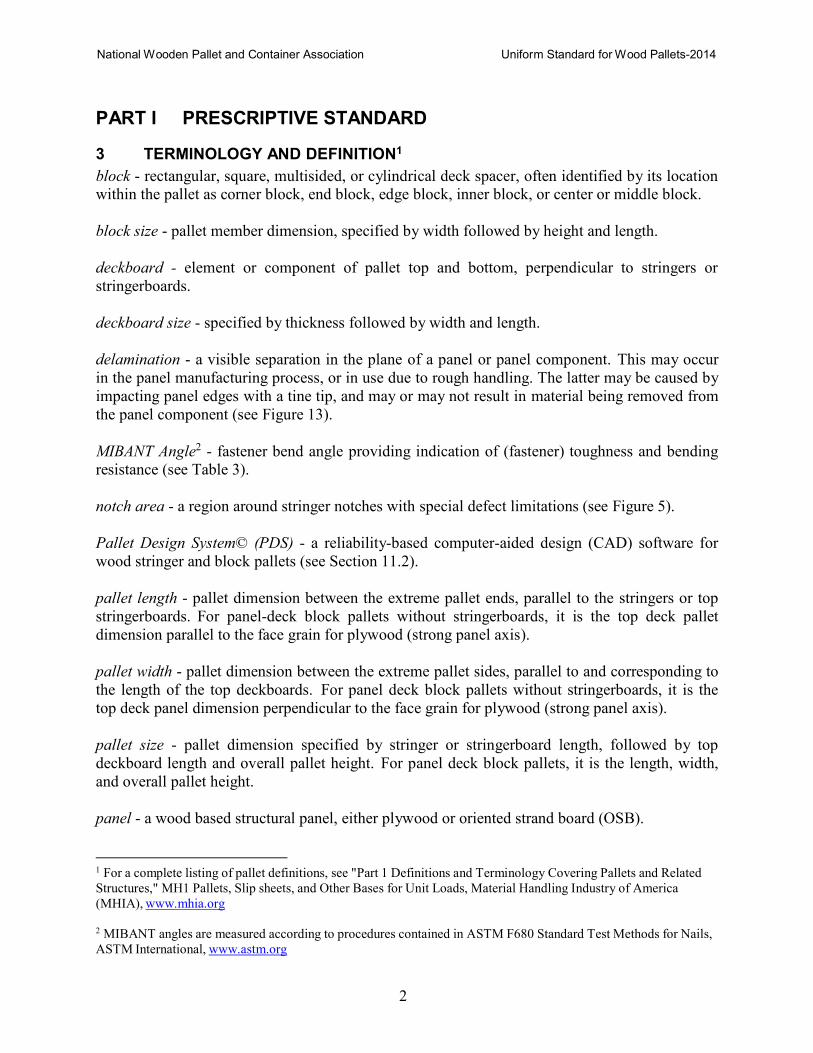
• Stringer Pallet (see Figure 1)
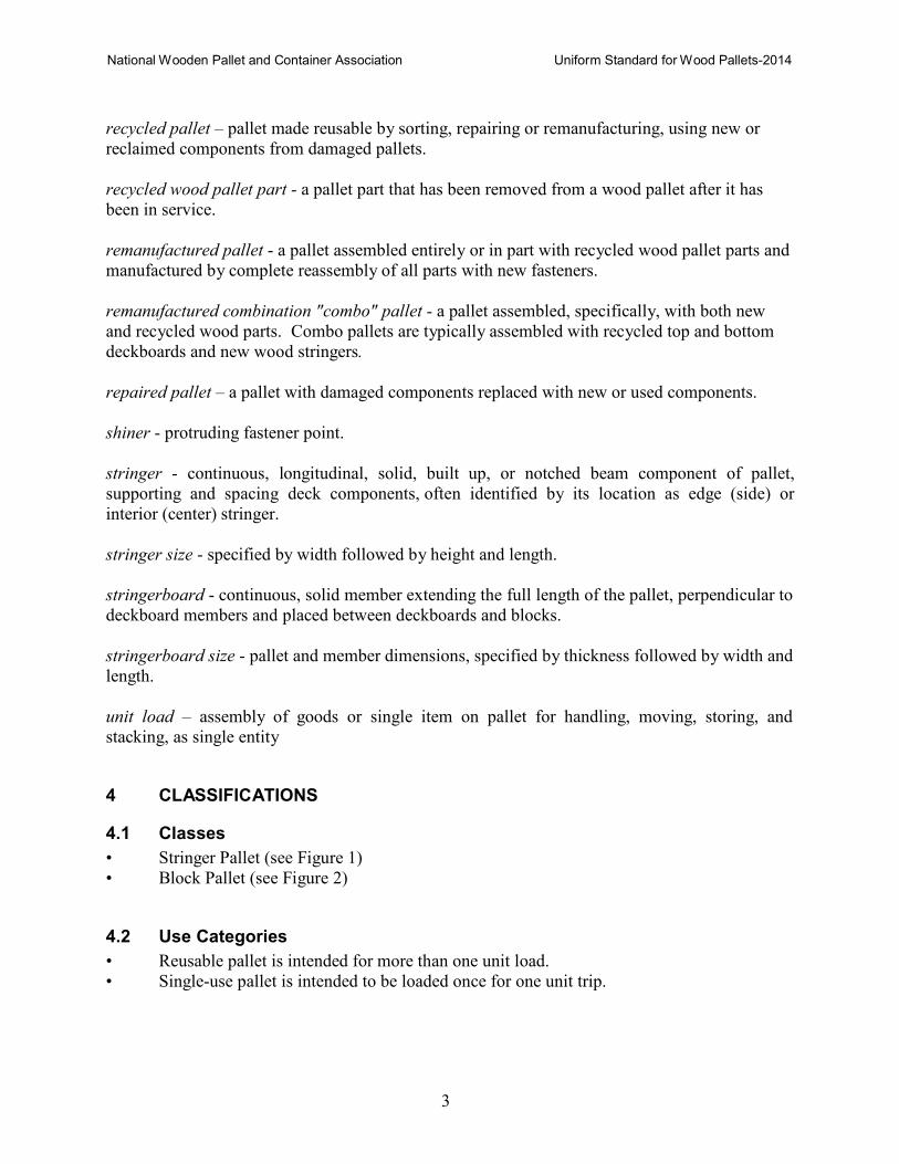
• Block Pallet (see Figure 2)
4.2 Use Categories
• Reusable pallet is intended for more than one unit load.
• Single-use pallet is intended to be loaded once for one unit trip.
National Wooden Pallet and Container Association Uniform Standard for Wood Pallets-2014
4
Figure 1. Schematic diagram of a typical stringer pallet with principal parts labeled.
Figure 2. Schematic diagram of a typical block pallet with principal parts labeled.
National Wooden Pallet and Container Association Uniform Standard for Wood Pallets-2014
5
4.3 Entry Types
• Two-way entry pallet with openings accepting handling equipment only in two pallet
ends, i.e. unnotched stringer pallet.
• Partial four-way entry pallet with openings at both ends and sides with limiting
accessibility of the openings to common handling equipment, i.e. notched stringer pallet
and block pallet with overlapping bottom stringerboards and bottom deckboards, or panels.
• Full four-way entry pallet with openings at both ends and sides with accessibility of all
openings not limited to standard handling equipment, i.e. block pallets with perimeter
boards, unidirectional, without bottom deckboards, or panel bottom decks with cutouts.
4.4 Styles
• Single-face
• Double-face, nonreversible
• Double-face, reversible
4.5 Top Deck Constructions
• Deckboard
• Deckboard/stringerboard
• Panel
• Panel/stringerboard
4.6 Bottom Deck Constructions
• Unidirectional bottom deckboards oriented in the direction of the pallet length or width
only.
• Overlapping bottom boards oriented in both directions of the length and width of the
pallet containing both bottom deckboards and bottom stringerboards.
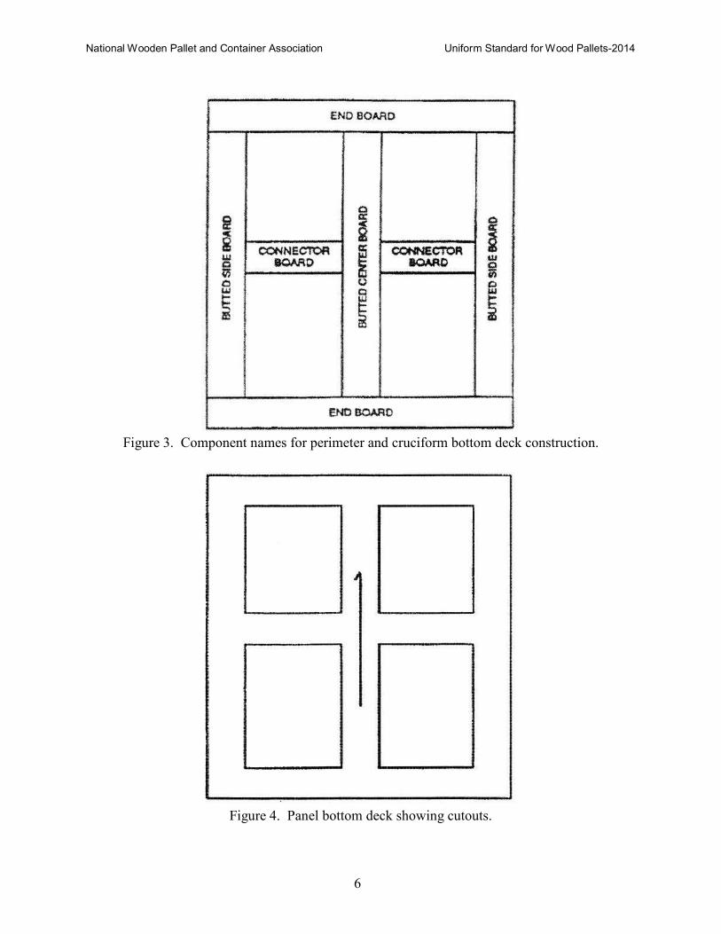
• Perimeter bottom deckboards oriented in both directions of the length and width of the
pallet containing butted boards and end boards (see Figure 3).
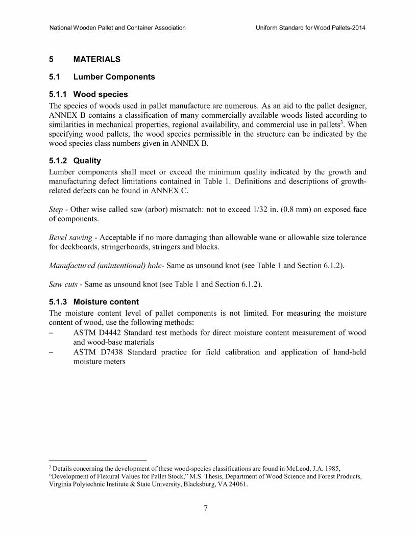
• Cruciform bottom deckboards oriented in both directions of the length and width of the
pallet containing butted boards, end boards, and connector boards (see Figure 3), or
panels with cutouts (see Figure 4).
4.7 Sizes
Each of the classified pallets is available in many sizes and designs. Therefore, size and
design details need to be specified.
National Wooden Pallet and Container Association Uniform Standard for Wood Pallets-2014
6
Figure 3. Component names for perimeter and cruciform bottom deck construction.
Figure 4. Panel bottom deck showing cutouts.
National Wooden Pallet and Container Association Uniform Standard for Wood Pallets-2014
7
5 MATERIALS
5.1 Lumber Components
5.1.1 Wood species
The species of woods used in pallet manufacture are numerous. As an aid to the pallet designer,
ANNEX B contains a classification of many commercially available woods listed according to
similarities in mechanical properties, regional availability, and commercial use in pallets3. When
specifying wood pallets, the wood species permissible in the structure can be indicated by the
wood species class numbers given in ANNEX B.
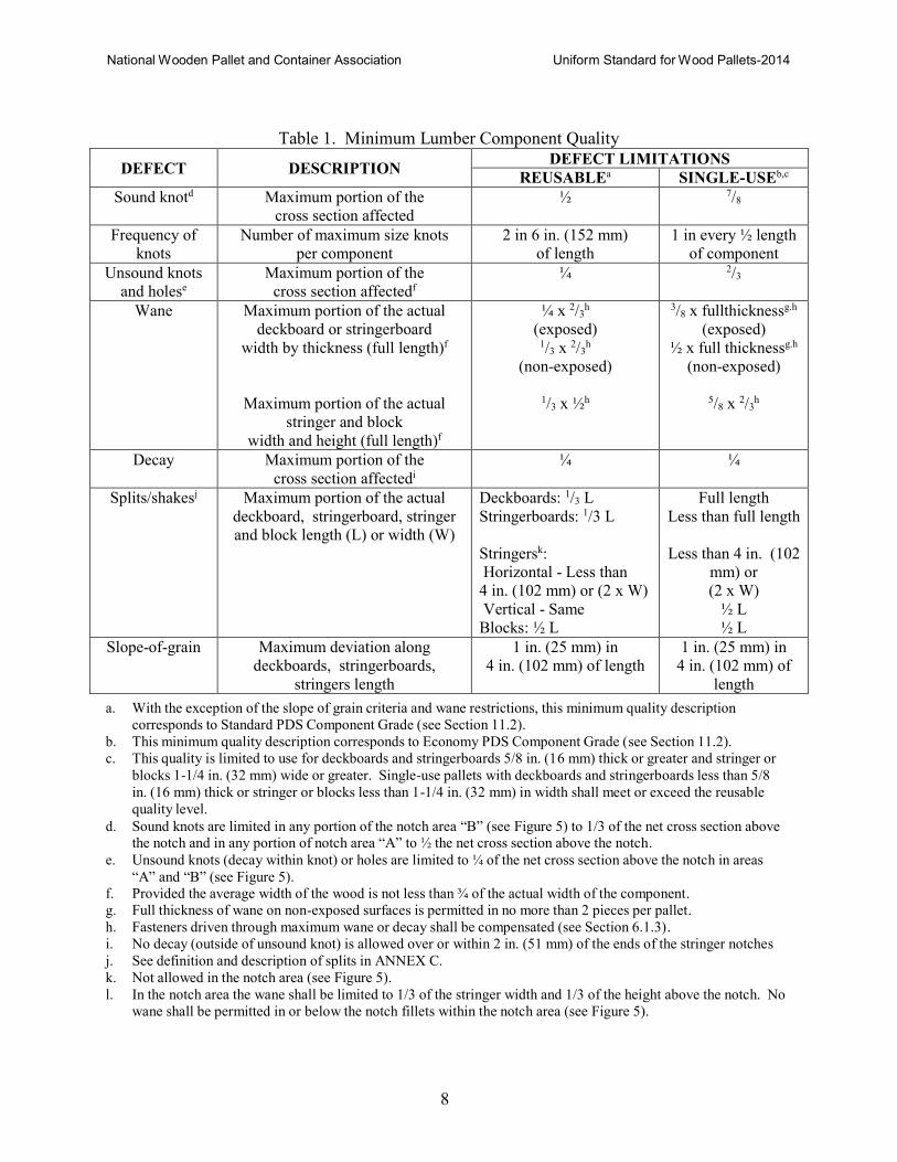
5.1.2 Quality
Lumber components shall meet or exceed the minimum quality indicated by the growth and
manufacturing defect limitations contained in Table 1. Definitions and descriptions of growth-
related defects can be found in ANNEX C.
Step - Other wise called saw (arbor) mismatch: not to exceed 1/32 in. (0.8 mm) on exposed face
of components.
Bevel sawing - Acceptable if no more damaging than allowable wane or allowable size tolerance
for deckboards, stringerboards, stringers and blocks.
Manufactured (unintentional) hole- Same as unsound knot (see Table 1 and Section 6.1.2).
Saw cuts - Same as unsound knot (see Table 1 and Section 6.1.2).
5.1.3 Moisture content
The moisture content level of pallet components is not limited. For measuring the moisture
content of wood, use the following methods:
− ASTM D4442 Standard test methods for direct moisture content measurement of wood
and wood-base materials
− ASTM D7438 Standard practice for field calibration and application of hand-held
moisture meters
3 Details concerning the development of these wood-species classifications are found in McLeod, J.A. 1985,
“Development of Flexural Values for Pallet Stock,” M.S. Thesis, Department of Wood Science and Forest Products,
Virginia Polytechnic Institute & State University, Blacksburg, VA 24061.
National Wooden Pallet and Container Association Uniform Standard for Wood Pallets-2014
8
Table 1. Minimum Lumber Component Quality
DEFECT DESCRIPTION DEFECT LIMITATIONS
REUSABLEa SINGLE-USEb,c
Sound knotd Maximum portion of the
cross section affected
½ 7/8
Frequency of
knots
Number of maximum size knots
per component
2 in 6 in. (152 mm)
of length
1 in every ½ length
of component
Unsound knots
and holese
Maximum portion of the
cross section affectedf
¼ 2/3
Wane Maximum portion of the actual
deckboard or stringerboard
width by thickness (full length)f
Maximum portion of the actual
stringer and block
width and height (full length)f
¼ x 2/3h
(exposed) 1/3 x 2/3
h
(non-exposed)
1/3 x ½h
3/8 x fullthicknessg.h
(exposed)
½ x full thicknessg.h
(non-exposed)
5/8 x 2/3
h
Decay Maximum portion of the
cross section affectedi
¼ ¼
Splits/shakesj Maximum portion of the actual
deckboard, stringerboard, stringer
and block length (L) or width (W)
Deckboards: 1/3 L
Stringerboards: 1/3 L
Stringersk:
Horizontal - Less than
4 in. (102 mm) or (2 x W)
Vertical - Same
Blocks: ½ L
Full length
Less than full length
Less than 4 in. (102
mm) or
(2 x W)
½ L
½ L
Slope-of-grain Maximum deviation along
deckboards, stringerboards,
stringers length
1 in. (25 mm) in
4 in. (102 mm) of length
1 in. (25 mm) in
4 in. (102 mm) of
length
a. With the exception of the slope of grain criteria and wane restrictions, this minimum quality description
corresponds to Standard PDS Component Grade (see Section 11.2).
b. This minimum quality description corresponds to Economy PDS Component Grade (see Section 11.2).
c. This quality is limited to use for deckboards and stringerboards 5/8 in. (16 mm) thick or greater and stringer or
blocks 1-1/4 in. (32 mm) wide or greater. Single-use pallets with deckboards and stringerboards less than 5/8
in. (16 mm) thick or stringer or blocks less than 1-1/4 in. (32 mm) in width shall meet or exceed the reusable
quality level.
d. Sound knots are limited in any portion of the notch area “B” (see Figure 5) to 1/3 of the net cross section above the notch and in any portion of notch area “A” to ½ the net cross section above the notch.
e. Unsound knots (decay within knot) or holes are limited to ¼ of the net cross section above the notch in areas
“A” and “B” (see Figure 5). f. Provided the average width of the wood is not less than ¾ of the actual width of the component.
g. Full thickness of wane on non-exposed surfaces is permitted in no more than 2 pieces per pallet.
h. Fasteners driven through maximum wane or decay shall be compensated (see Section 6.1.3).
i. No decay (outside of unsound knot) is allowed over or within 2 in. (51 mm) of the ends of the stringer notches
j. See definition and description of splits in ANNEX C.
k. Not allowed in the notch area (see Figure 5).
l. In the notch area the wane shall be limited to 1/3 of the stringer width and 1/3 of the height above the notch. No
wane shall be permitted in or below the notch fillets within the notch area (see Figure 5).
National Wooden Pallet and Container Association Uniform Standard for Wood Pallets-2014
9
5.1.4 Preparation
Lumber component tolerances apply at any moisture content.
5.1.4.1 Dimensions Lumber components shall have a target thickness and width uniform in dimension and 50% of
components shall meet or exceed the target dimension at the time of component manufacture.
Based on current Good Manufacturing Practices (GMP), the target thickness of deckboards and
stringerboards may deviate ±1/32 in. (±0.8 mm). The target width and height of stringers and
blocks may exceed the specified dimensions by a maximum of 1/8 in. (3 mm) and 1/4 in. (6
mm), respectively.
The following are acceptable manufacturing tolerances allowed on established target dimensions:
Deckboards and Stringerboards
Thicknesses: ±1/16 in. (±1.6 mm) maximum deviation (including target deviation of 1/32 in. [±0.8 mm])
Width: +unlimited, -1/4 in. (-6 mm) maximum deviation
Length: +1/8 in. (+3 mm), -1/4 in. (-6 mm) maximum deviation
Stringers and Blocks
Width: ±1/16 in. (±1.6 mm) maximum deviation
Height: ±1/16 in. (±1.6 mm) maximum deviation
Length: +1/8 in. (+3 mm), -1/4 in. (-6 mm) maximum deviation
Conformance to these manufacturing tolerances in components and pallets can be expressed
using standard statistics reflecting variations equal to or less than those permitted in this Standard.
Two standard deviations from target size shall be less than the tolerances specified.
5.1.4.2 Deckboard chamfer The deckboard chamfers, if specified, shall be located on both outside faces of bottom end
boards and all interior edges of bottom boards adjoining wheel openings. The chamfers shall be
at least 12 in. (305 mm) long and at an angle between 35 to 45º, located 1/4 in. (6 mm), ±1/8 in.
(±3 mm) from the bottom of the board. Chamfers shall not extend into connections.
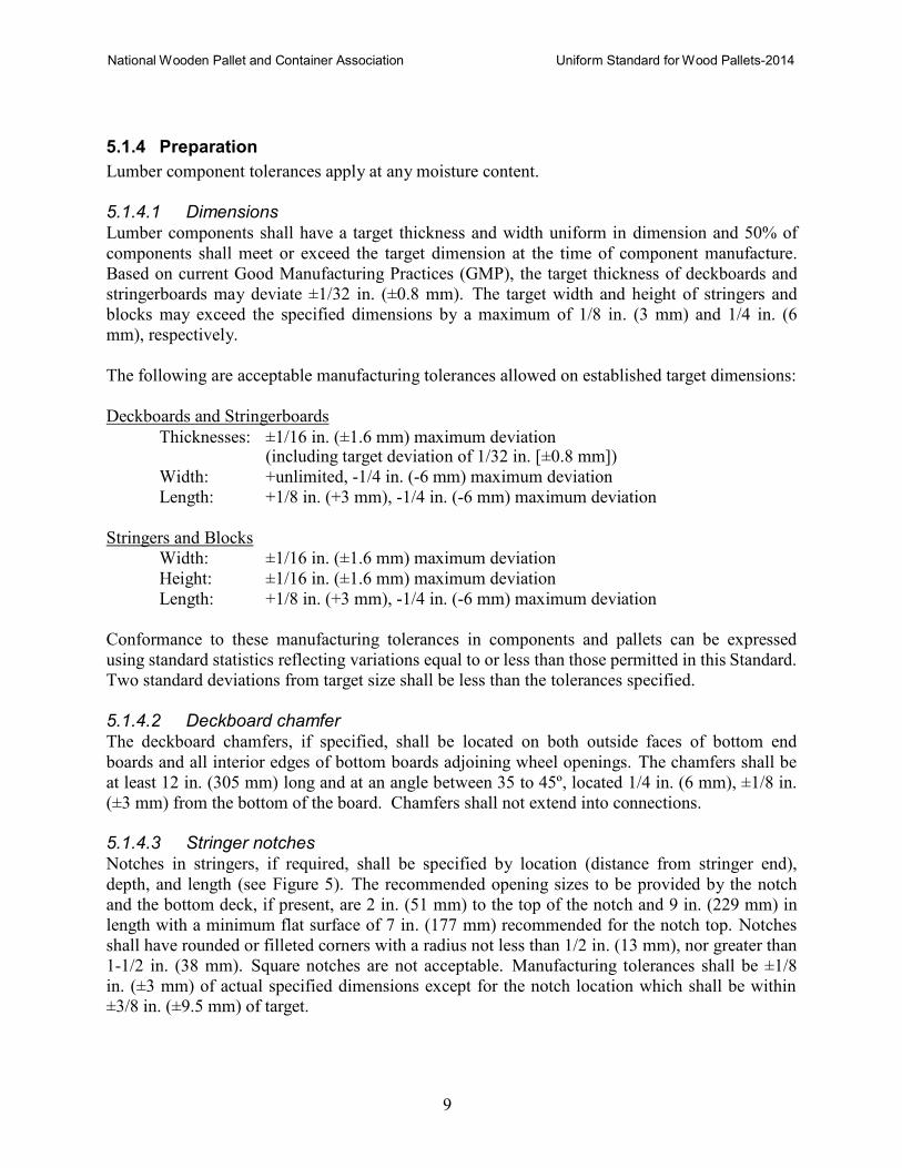
5.1.4.3 Stringer notches Notches in stringers, if required, shall be specified by location (distance from stringer end),
depth, and length (see Figure 5). The recommended opening sizes to be provided by the notch
and the bottom deck, if present, are 2 in. (51 mm) to the top of the notch and 9 in. (229 mm) in
length with a minimum flat surface of 7 in. (177 mm) recommended for the notch top. Notches
shall have rounded or filleted corners with a radius not less than 1/2 in. (13 mm), nor greater than
1-1/2 in. (38 mm). Square notches are not acceptable. Manufacturing tolerances shall be ±1/8
in. (±3 mm) of actual specified dimensions except for the notch location which shall be within
±3/8 in. (±9.5 mm) of target.
National Wooden Pallet and Container Association Uniform Standard for Wood Pallets-2014
10
Figure 5. Schematic diagram of a pallet stringer with notch features.
5.2 Wood Panel (Plywood or OSB) Components
5.2.1 Quality
Wood panels shall conform to the latest edition of one of the following standards:
− PS 1-07 Structural Plywood
− PS 2-04 Performance Standard for Wood-Based Structural-Use Panels
− PRP 108 Performance Standards and Policies for Structural-Use Panels
− ANSI/HPVA HP-1-2004 American National Standard for Hardwood and Decorative
Plywood
Each panel deck piece shall be identified with the appropriate trademark of a recognized grading
agency (see ANNEX D). The firm supplying the panels shall furnish certification that the
original panels were trademarked.
All panels used for pallet components shall be bonded with exterior (fully waterproof) adhesive.
Panels that exceed the delamination limits of the standards listed in this Section as a result of
their manufacturing process are not permitted to be used for new, repaired or remanufactured
pallets.
5.2.2 Grade
Unless specified otherwise by the purchaser, panels for panel decks shall be either: Rated
Sheathing, Exposure 1; or Rated Sturd-l-Floor, Exposure 1. Exterior is an acceptable alternative
to Exposure 1. Panels of any grade may be used to fabricate laminated pallet blocks.
5.2.3 Preparation
5.2.3.1 Dimensions Panel decks for block class pallets shall consist of a single piece. Panel decks for stringer class
pallets shall be oriented with the plywood face grain (strong panel axis) perpendicular to the
stringers, and may consist of more than one piece, provided the minimum width (perpendicular
to plywood face grain or strong panel axis) of any piece is 24 in. (610 mm) or greater, and the
panel joints are perpendicular to the stringers.
National Wooden Pallet and Container Association Uniform Standard for Wood Pallets-2014
11
Wood panel components shall have a target thickness and width uniform in dimension and 50%
of components must meet or exceed the target dimension at the time of component manufacture.
Based on current GMP, the target thickness of panel decks and plywood strip bottom deckboards
may deviate ±1/32 in. (±0.8 mm).
Blocks may be laminated from panel components. The target width, length and height of
finished panel component blocks may exceed the specified dimensions by a maximum of 1/8 in.
(3 mm). Sides shall not deviate from being square to the block top or bottom by more than 1/8
in. (3 mm), and any deviation from square shall not be in addition to the target width and length.
The face grain of plywood strip bottom deckboards shall run in the direction of the deckboards'
length. OSB strips are not permitted to be used as bottom deckboards.
The following are acceptable manufacturing tolerances allowed on established target dimensions.
Panel Decks and Plywood Strip Bottom Deckboards
Plywood strip bottom deckboards and panel areas around cutouts shall be not less than 6 in. (152 mm) wide
Thicknesses: ±1/32 in. (±0.8 mm) maximum deviation
Length and Width: ±1/8 in. (±3 mm)
Laminated Blocks (including individual laminations)
Width: ±1/8 in. (±3 mm) maximum deviation Height: ±1/16 in. (±1.6 mm) maximum deviation
Length: ±1/8 in. (±3 mm) maximum deviation
Conformance to these manufacturing tolerances in components and pallets can be expressed
using standard statistics reflecting variations equal to or less than those permitted in this Standard.
Two standard deviations from target size shall be less than the tolerances specified.
5.2.3.2 Panel Decks and Plywood Strip Bottom Deckboard Chamfer
The deckboard chamfers if specified, shall be located on both outside faces of bottom end boards
and all interior and exterior edges of panel bottom decks adjoining wheel openings. The chamfers
shall extend the full width of the openings, and shall be at an angle of 35 to 45º located 1/4 in. (6
mm), ±1/8 in. (±3 mm) from bottom of deck or board.
5.2.3.3 Laminated Pallet Blocks
Pallet blocks may be laminated from panel components using either fasteners (see Section 6.2.6)
or adhesives. A water resistant adhesive shall be used and applied according to manufacturers'
recommendations.
National Wooden Pallet and Container Association Uniform Standard for Wood Pallets-2014
12
5.3 Wood-based Composites Components
5.3.1 Quality High-density moisture-resistant wood-based composite blocks shall meet or exceed the following criteria:
Density: 36.9 – 42.1 lbs. ft3 (591 – 675 kg/m3)
Adhesive: only approved glue and additives that can assure the stability of the blocks
can be used as bonding agents
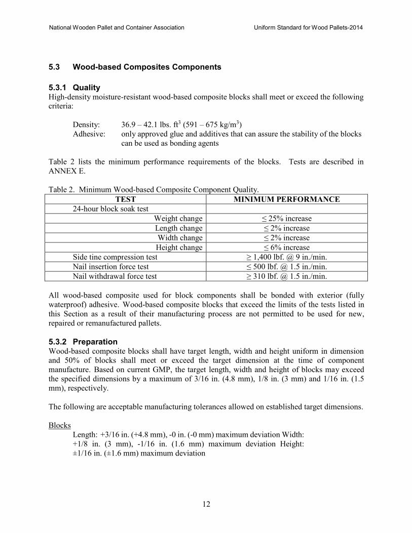
Table 2 lists the minimum performance requirements of the blocks. Tests are described in
ANNEX E.
Table 2. Minimum Wood-based Composite Component Quality.
TEST MINIMUM PERFORMANCE
24-hour block soak test
Weight change ≤ 25% increase
Length change ≤ 2% increase
Width change ≤ 2% increase
Height change ≤ 6% increase
Side tine compression test ≥ 1,400 lbf. @ 9 in./min.
Nail insertion force test ≤ 500 lbf. @ 1.5 in./min.
Nail withdrawal force test ≥ 310 lbf. @ 1.5 in./min.
All wood-based composite used for block components shall be bonded with exterior (fully
waterproof) adhesive. Wood-based composite blocks that exceed the limits of the tests listed in
this Section as a result of their manufacturing process are not permitted to be used for new,
repaired or remanufactured pallets.
5.3.2 Preparation Wood-based composite blocks shall have target length, width and height uniform in dimension and 50% of blocks shall meet or exceed the target dimension at the time of component
manufacture. Based on current GMP, the target length, width and height of blocks may exceed
the specified dimensions by a maximum of 3/16 in. (4.8 mm), 1/8 in. (3 mm) and 1/16 in. (1.5
mm), respectively.
The following are acceptable manufacturing tolerances allowed on established target dimensions.
Blocks
Length: +3/16 in. (+4.8 mm), -0 in. (-0 mm) maximum deviation Width:
+1/8 in. (3 mm), -1/16 in. (1.6 mm) maximum deviation Height:
±1/16 in. (±1.6 mm) maximum deviation
National Wooden Pallet and Container Association Uniform Standard for Wood Pallets-2014
13
Conformance to these manufacturing tolerances in components and pallets can be expressed
using standard statistics reflecting variations equal to or less than those permitted in this Standard.
Two standard deviations from target size shall be less than the tolerances specified.
5.4 Engineered Wood Components
5.4.1 Quality High-density moisture-resistant engineered wood laminates shall meet or exceed the following standards:
− ASTM D3043 Standard test methods for structural panels in flexure
− ASTM D4761 Standard test methods for mechanical properties of lumber and wood-base
structural material
All engineered wood components used for deckboards and stringers shall be bonded with exterior
(fully waterproof) adhesive. Engineered wood that fail the test methods of the standards listed in
this Section as a result of their manufacturing process are not permitted to be used for new,
repaired or remanufactured pallets.
5.4.2 Preparation Engineered wood components shall have target thickness and width uniform in dimension and 50% of components shall meet or exceed the target dimension at the time of component
manufacture. Based on current GMP, the target length, width and height of deckboard or
stringer may exceed the specified dimensions by a maximum of 3/16 in. (4.8 mm), 1/8 in. (3
mm) and 1/16 in. (1.6 mm), respectively.
The following are acceptable manufacturing tolerances allowed on established target dimensions:
Deckboards and Stringerboards
Thicknesses: ±1/16 in. (±1.6 mm) maximum deviation
(including target deviation of 1/32 in. [±0.8 mm])
Width: +unlimited, -1/4 in. (-6 mm) maximum deviation
Length: +1/8 in. (+3 mm), -1/4 in. (-6 mm) maximum deviation
Stringers
Width: ±1/16 in. (±1.6 mm) maximum deviation
Height: ±1/16 in. (±1.6 mm) maximum deviation
Length: +1/8 in. (+3 mm), -1/4 in. (-6 mm) maximum deviation
Conformance to these manufacturing tolerances in components and pallets can be expressed
using standard statistics reflecting variations equal to or less than those permitted in this Standard.
Two standard deviations from target size shall be less than the tolerances specified.
National Wooden Pallet and Container Association Uniform Standard for Wood Pallets-2014
14
5.5 Fasteners
Fasteners are classified as driven nails and staples, bolts, wood screws, and lag screws. The
types and properties of fasteners affect pallet performance.
5.5.1 Driven Fasteners
Driven fasteners include nails and staples. As used in pallets, nails are classified as plain shank,
helically threaded, annularly threaded, fluted, or twisted square wire. Staples have either round
wire or approximately square wire legs, referring to the cross sectional shape of the wire. All
driven fasteners shall be specified using either of three methods:
1. Direct measurement of the physical and mechanical characteristics (indicated in Table 3
and Figure 6); and
2. Specification of connection design properties, or
3. Both 1 and 2.
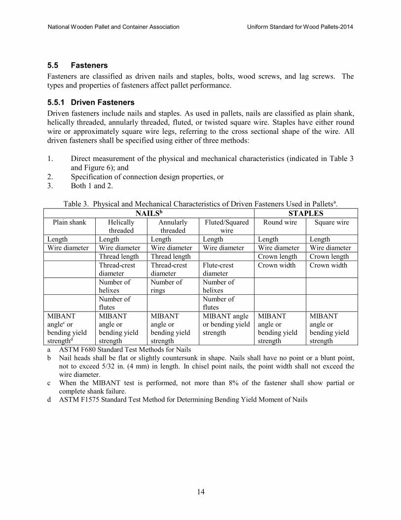
Table 3. Physical and Mechanical Characteristics of Driven Fasteners Used in Palletsa.
NAILSb STAPLES Plain shank Helically
threaded
Annularly
threaded
Fluted/Squared
wire
Round wire Square wire
Length Length Length Length Length Length
Wire diameter Wire diameter Wire diameter Wire diameter Wire diameter Wire diameter
Thread length Thread length Crown length Crown length
Thread-crest diameter
Thread-crest diameter
Flute-crest diameter
Crown width Crown width
Number of helixes
Number of rings
Number of helixes
Number of flutes
Number of flutes
MIBANT
anglec or
bending yield
strengthd
MIBANT
angle or
bending yield
strength
MIBANT
angle or
bending yield
strength
MIBANT angle
or bending yield
strength
MIBANT
angle or
bending yield
strength
MIBANT
angle or
bending yield
strength
a ASTM F680 Standard Test Methods for Nails
b Nail heads shall be flat or slightly countersunk in shape. Nails shall have no point or a blunt point,
not to exceed 5/32 in. (4 mm) in length. In chisel point nails, the point width shall not exceed the
wire diameter.
c When the MIBANT test is performed, not more than 8% of the fastener shall show partial or
complete shank failure.
d ASTM F1575 Standard Test Method for Determining Bending Yield Moment of Nails
National Wooden Pallet and Container Association Uniform Standard for Wood Pallets-2014
15
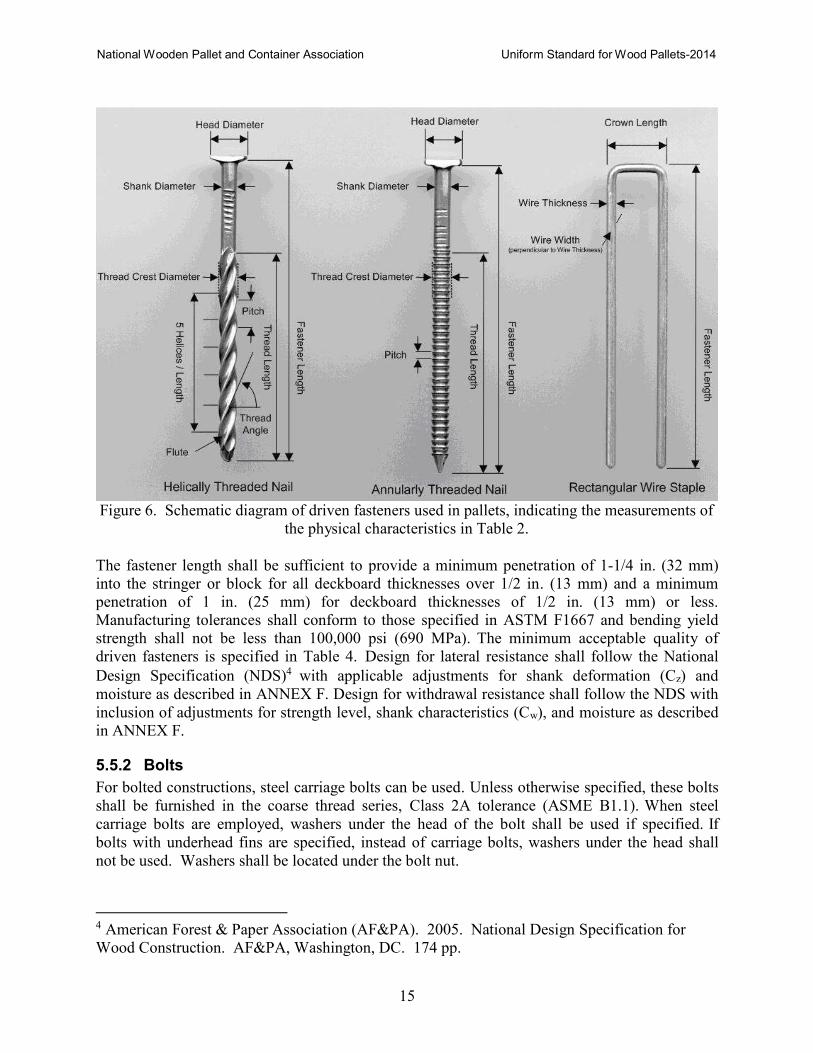
Figure 6. Schematic diagram of driven fasteners used in pallets, indicating the measurements of
the physical characteristics in Table 2.
The fastener length shall be sufficient to provide a minimum penetration of 1-1/4 in. (32 mm)
into the stringer or block for all deckboard thicknesses over 1/2 in. (13 mm) and a minimum
penetration of 1 in. (25 mm) for deckboard thicknesses of 1/2 in. (13 mm) or less.
Manufacturing tolerances shall conform to those specified in ASTM F1667 and bending yield
strength shall not be less than 100,000 psi (690 MPa). The minimum acceptable quality of
driven fasteners is specified in Table 4. Design for lateral resistance shall follow the National
Design Specification (NDS)4 with applicable adjustments for shank deformation (Cz) and
moisture as described in ANNEX F. Design for withdrawal resistance shall follow the NDS with
inclusion of adjustments for strength level, shank characteristics (Cw), and moisture as described
in ANNEX F.
5.5.2 Bolts
For bolted constructions, steel carriage bolts can be used. Unless otherwise specified, these bolts
shall be furnished in the coarse thread series, Class 2A tolerance (ASME B1.1). When steel
carriage bolts are employed, washers under the head of the bolt shall be used if specified. If
bolts with underhead fins are specified, instead of carriage bolts, washers under the head shall
not be used. Washers shall be located under the bolt nut.
4 American Forest & Paper Association (AF&PA). 2005. National Design Specification for
Wood Construction. AF&PA, Washington, DC. 174 pp.
National Wooden Pallet and Container Association Uniform Standard for Wood Pallets-2014
16
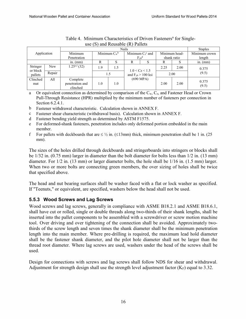
Table 4. Minimum Characteristics of Driven Fastenersa for Single-
use (S) and Reusable (R) Pallets
Application
Nails Staples
Minimum
Penetration
Minimum Cwb Minimum Cz
c and
Fybd
Minimum head-
shank ratio
Minimum crown
length
in. (mm) R S R S R S in. (mm)
Stringer
or block
pallets
New 1.25e,f (32) 1.9 1.5
1.0 < Cz < 1.5
and Fyb > 100 ksi
(690 MPA)
2.25 2.00 0.375
(9.5) Repair 1.5 2.00
Clinched
mat
All Complete
penetration and
clinched
1.0 1.0 2.00 2.00 0.375
(9.5)
a Or equivalent connection as determined by comparison of the Cw, Cz, and Fastener Head or Crown Pull-Through Resistance (HPR) multiplied by the minimum number of fasteners per connection in
Section 6.2.4.1.
b Fastener withdrawal characteristic. Calculation shown in ANNEX F. c Fastener shear characteristic (withdrawal basis). Calculation shown in ANNEX F.
d Fastener bending yield strength as determined by ASTM F1575.
e For deformed-shank fasteners, penetration includes only deformed portion embedded in the main
member.
f For pallets with deckboards that are ≤ ½ in. (≤13mm) thick, minimum penetration shall be 1 in. (25
mm).
The sizes of the holes drilled through deckboards and stringerboards into stringers or blocks shall
be 1/32 in. (0.75 mm) larger in diameter than the bolt diameter for bolts less than 1/2 in. (13 mm)
diameter. For 1/2 in. (13 mm) or larger diameter bolts, the hole shall be 1/16 in. (1.5 mm) larger.
When two or more bolts are connecting green members, the over sizing of holes shall be twice
that specified above.
The head and nut bearing surfaces shall be washer faced with a flat or lock washer as specified.
If "Teenuts," or equivalent, are specified, washers below the head shall not be used.
5.5.3 Wood Screws and Lag Screws
Wood screws and lag screws, generally in compliance with ASME B18.2.1 and ASME B18.6.1,
shall have cut or rolled, single or double threads along two-thirds of their shank lengths, shall be
inserted into the pallet components to be assembled with a screwdriver or screw motion machine
tool. Over driving and over tightening of the connection shall be avoided. Approximately two-
thirds of the screw length and seven times the shank diameter shall be the minimum penetration
length into the main member. Where pre-drilling is required, the maximum lead hold diameter
shall be the fastener shank diameter, and the pilot hole diameter shall not be larger than the
thread root diameter. Where lag screws are used, washers under the head of the screws shall be
used.
Design for connections with screws and lag screws shall follow NDS for shear and withdrawal.
Adjustment for strength design shall use the strength level adjustment factor (KF) equal to 3.32.
National Wooden Pallet and Container Association Uniform Standard for Wood Pallets-2014
17
6 MANUFACTURE OF PALLETS
6.1 Component Defects
For definitions and classifications, see ANNEX C.
6.1.1 Sound knots
Fasteners may be driven through sound knots.
6.1.2 Unsound knots and holes
Fasteners shall be compensated when associated with unsound knots or holes. Unsound knots or
holes shall not be permitted in the outer edge of end boards, nor on the exposed ends of stringers
or blocks.
6.1.3 Wane and decay
Wane and decay are permitted on any component; provided it is not located on the outer edge of
endboards, or on the exposed sides of stringers or blocks. Decay is not permitted in the notch
area (see Figure 5). Wane may appear on the surface or edge of other components; but in no
case shall fasteners be driven into or through either defect. Not more than one third (33%) of the
components in a pallet may contain wane. Any fastener associated with maximum wane shall be
compensated.
6.1.4 Splits and shake
Splits and shakes running the full thickness of a component (not applicable to nail splits) shall be
straddled with fasteners in the top and bottom end deckboards and butted side bottom
deckboards.
6.1.5 Panel components
Knots, knotholes, splits in individual veneers and other voids do not affect the strength and
stiffness of plywood panels having a minimum dimension of 24 in. (600 mm). For widths less
than 24 in. (600 mm), the plywood face shall not have knots, plugs, or open defects (knotholes
and splits) that aggregate more than one fourth the width of either face ply at any cross section of
the piece.
6.2 Assembly
6.2.1 Wood component placement
The placement of wood components shall be as follows:
− All leading deckboards shall be within ±1/4 in. (±6 mm) of their specified location.
− Other wood components shall be within ±1/2 in. (±13 mm) of their specified location,
except that bottom boards shall not extend into the stringer notch.
Maximum placement deviation shall be limited to one third of the components in any pallet. All
similar components shall be placed parallel unless otherwise specified.
National Wooden Pallet and Container Association Uniform Standard for Wood Pallets-2014
18
6.2.2 Pallet size deviation
The pallet size shall be limited to plus +1/4 in. (+6 mm) and -1/2 in. (-13 mm) of the target
dimension, as measured at specific points along the pallet length and width. The pallets must be
flat on their top and bottom surfaces to within 1/4 in. (6 mm) maximum deviation from the
corner-to corner straight line.
6.2.3 Squareness
Square or rectangular pallets shall be limited to 1.5% or 1 in. (25 mm) difference in the measured
top deck diagonals, whichever is greater.
6.2.4 Fastening - driven fasteners
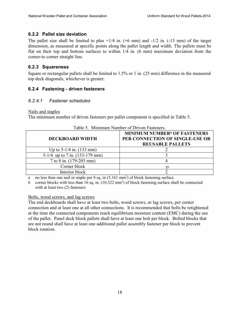
6.2.4.1 Fastener schedules
Nails and staples
The minimum number of driven fasteners per pallet component is specified in Table 5.
Table 5. Minimum Number of Driven Fasteners.
DECKBOARD WIDTH
MINIMUM NUMBERa OF FASTENERS
PER CONNECTION OF SINGLE-USE OR
REUSABLE PALLETS
Up to 5-1/4 in. (133 mm) 2
5-1/4 up to 7 in. (133-179 mm) 3
7 to 8 in. (179-203 mm) 4
Corner block 3b
Interior block 2
a no less than one nail or staple per 8 sq. in (5,161 mm2) of block fastening surface
b corner blocks with less than 16 sq. in. (10,322 mm2) of block fastening surface shall be connected
with at least two (2) fasteners
Bolts, wood screws, and lag screws
The end deckboards shall have at least two bolts, wood screws, or lag screws, per corner
connection and at least one at all other connections. It is recommended that bolts be retightened
at the time the connected components reach equilibrium moisture content (EMC) during the use
of the pallet. Panel deck block pallets shall have at least one bolt per block. Bolted blocks that
are not round shall have at least one additional pallet assembly fastener per block to prevent
block rotation.
National Wooden Pallet and Container Association Uniform Standard for Wood Pallets-2014
19
6.2.4.2 Fastener placement Fasteners shall be placed in such a way as to minimize splitting of the connected components.
Staple crowns shall not be parallel to the grain of the deck components. A combination of the
various fastener types in a single connection shall not be permitted if they do not interact
effectively; that is, simultaneously contributes to the stiffness and strength, or both, of the
connection. For example, bolts in oversize holes and driven fasteners represent a poor
combination and cannot be expected to work in unison. They shall not be placed in the same
connection or different connections of an assembly.
Panel deck stringer pallets shall have a minimum of three fasteners at the end of each stringer
starting 1 in. (25 mm) in from the end and spaced 2 in. (51 mm) on center. Interior fasteners
shall be spaced a maximum of 10 in. (254 mm) on center. When using laminated blocks, the
fastener length requires a minimum of 1 in. (25 mm) overlap between the top and bottom deck
fasteners (see Figure 7).
6.2.4.3 Clinching points of driven fasteners Clinched fasteners shall be at least ¼ in. (6 mm) longer than the sum of the thicknesses of the
components being fastened and driven in such a manner as to prevent buckling of the fastener
under the crown or head.
6.2.4.4 Fastener caused splits Open splits with visible fastener shanks or legs shall be limited. No more than one open split
with a visible fastener shank or leg per connection shall be permitted and not more than 1/3 of the components per pallet shall contain open splits with visible fastener shanks or legs at the completion of manufacture.
6.2.4.5 Protruding fasteners Nail heads, staple crowns, bolt heads, nuts, and screw heads shall be flush or below deck
surfaces. Countersinking fastener heads and protruding fastener points shall not significantly
affect pallet performance. No protruding fastener points (shiners) shall be permitted on the
exposed face of outside stringers or blocks or in lead deckboard areas. Two protruding fasteners
on unexposed surfaces are permitted so long as they do not significantly affect pallet
performance. Protruding fastener points are not permitted when using non clinched fasteners to
attach deckboards to stringerboards in block class pallets. Fasteners not driven into stringers and
blocks shall be compensated.
6.2.5 Fastening - chemical adhesives or glues
Adhesives shall only be used in conjunction with driven fasteners conforming to Section 5.5.
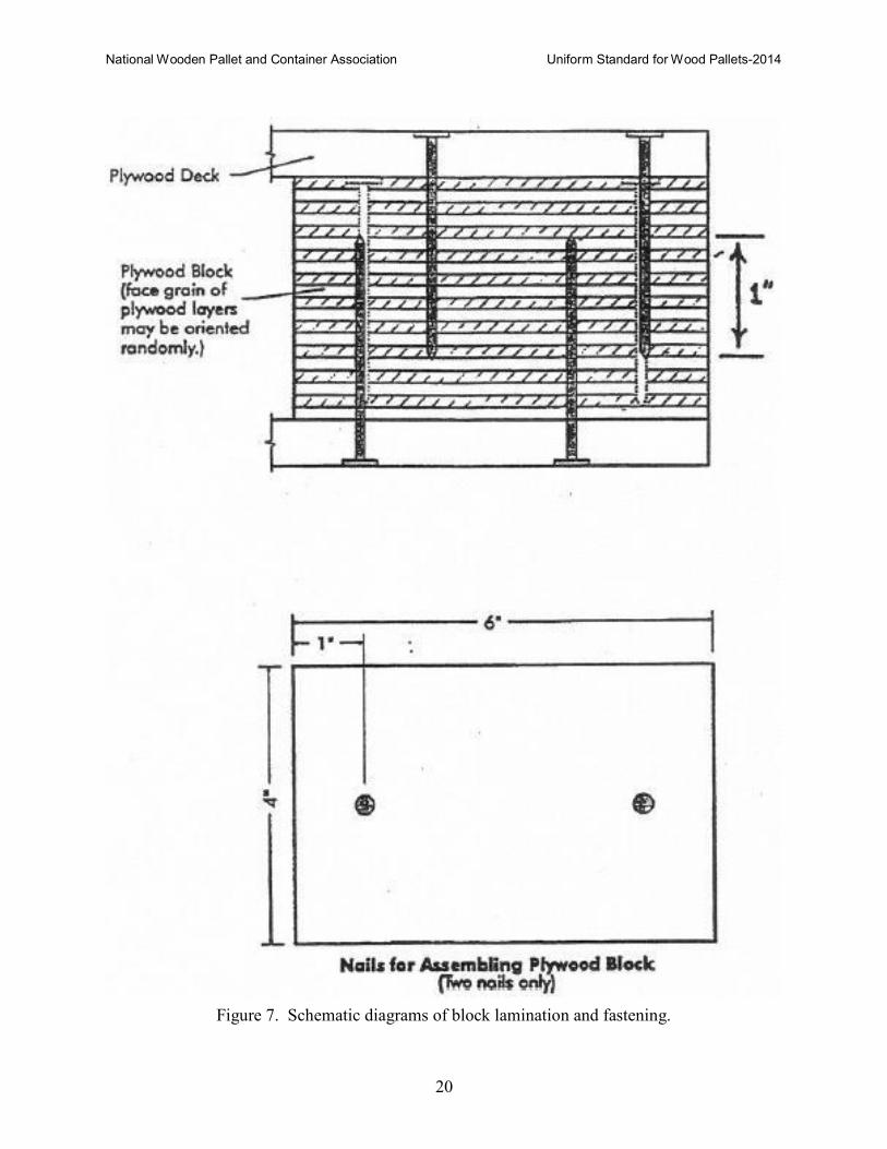
6.2.6 Laminated block fastening schedule
Laminated blocks shall be assembled with a minimum of two fasteners driven through either face
conforming to the quality requirements of Table 3, but equal to the block height [1/2 in. (13 mm)
if countersunk 1/4 in. (6 mm)] (see Figure 7).
National Wooden Pallet and Container Association Uniform Standard for Wood Pallets-2014
20
Figure 7. Schematic diagrams of block lamination and fastening.
National Wooden Pallet and Container Association Uniform Standard for Wood Pallets-2014
21
7 REPAIR OF PALLETS
Properly repairing and recycling wood pallets is an environmentally conscientious practice,
which also increases unit load material handling efficiency and reduces the cost of product
storage and distribution. All pallets should be removed from service and be repaired, recycled or
properly disposed of, if determined to be unsafe to persons or goods.
7.1 Damages
Damages which should be repaired in pallets with lumber, panel, wood-based composite, or
engineered wood components:
7.1.1 Missing deckboards, stringers, blocks, or stringerboards.
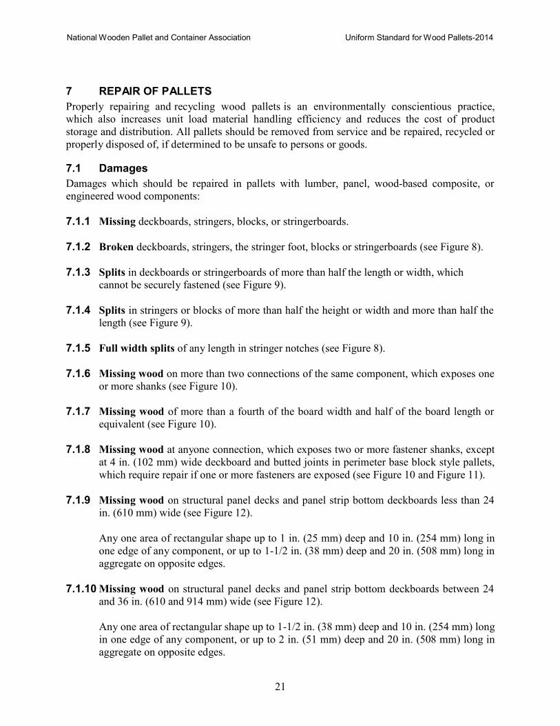
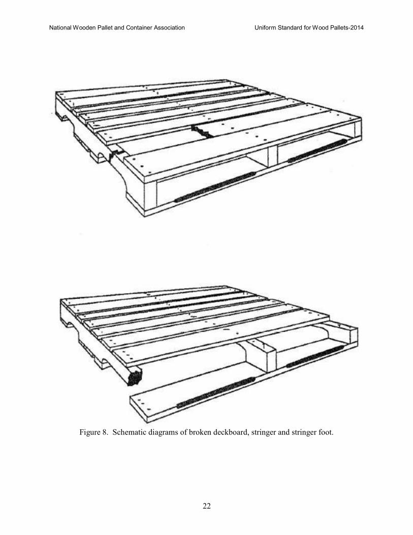
7.1.2 Broken deckboards, stringers, the stringer foot, blocks or stringerboards (see Figure 8).
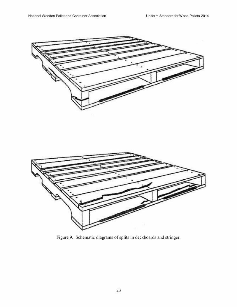
7.1.3 Splits in deckboards or stringerboards of more than half the length or width, which
cannot be securely fastened (see Figure 9).
7.1.4 Splits in stringers or blocks of more than half the height or width and more than half the
length (see Figure 9).
7.1.5 Full width splits of any length in stringer notches (see Figure 8).
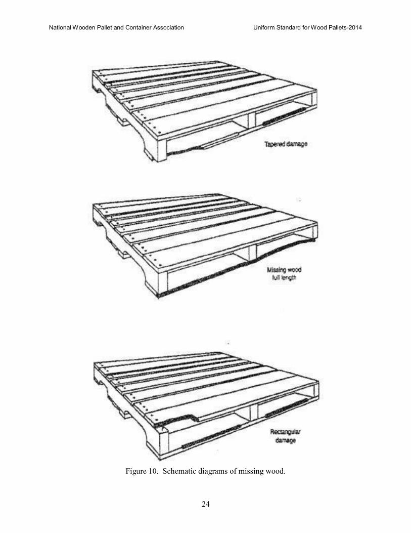
7.1.6 Missing wood on more than two connections of the same component, which exposes one
or more shanks (see Figure 10).
7.1.7 Missing wood of more than a fourth of the board width and half of the board length or
equivalent (see Figure 10).
7.1.8 Missing wood at anyone connection, which exposes two or more fastener shanks, except
at 4 in. (102 mm) wide deckboard and butted joints in perimeter base block style pallets,
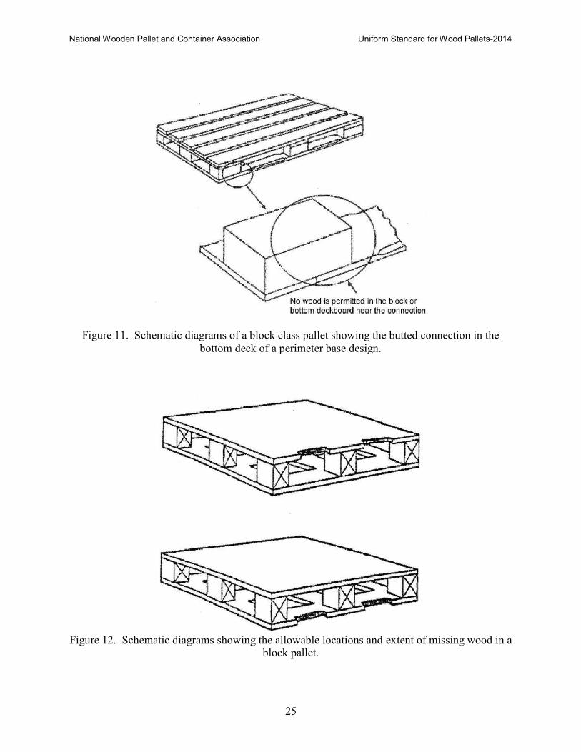
which require repair if one or more fasteners are exposed (see Figure 10 and Figure 11).
7.1.9 Missing wood on structural panel decks and panel strip bottom deckboards less than 24
in. (610 mm) wide (see Figure 12).
Any one area of rectangular shape up to 1 in. (25 mm) deep and 10 in. (254 mm) long in
one edge of any component, or up to 1-1/2 in. (38 mm) deep and 20 in. (508 mm) long in
aggregate on opposite edges.
7.1.10 Missing wood on structural panel decks and panel strip bottom deckboards between 24
and 36 in. (610 and 914 mm) wide (see Figure 12).
Any one area of rectangular shape up to 1-1/2 in. (38 mm) deep and 10 in. (254 mm) long
in one edge of any component, or up to 2 in. (51 mm) deep and 20 in. (508 mm) long in
aggregate on opposite edges.
National Wooden Pallet and Container Association Uniform Standard for Wood Pallets-2014
22
Figure 8. Schematic diagrams of broken deckboard, stringer and stringer foot.
National Wooden Pallet and Container Association Uniform Standard for Wood Pallets-2014
23
Figure 9. Schematic diagrams of splits in deckboards and stringer.
National Wooden Pallet and Container Association Uniform Standard for Wood Pallets-2014
24
Figure 10. Schematic diagrams of missing wood.
National Wooden Pallet and Container Association Uniform Standard for Wood Pallets-2014
25
Figure 11. Schematic diagrams of a block class pallet showing the butted connection in the
bottom deck of a perimeter base design.
Figure 12. Schematic diagrams showing the allowable locations and extent of missing wood in a
block pallet.
National Wooden Pallet and Container Association Uniform Standard for Wood Pallets-2014
26
7.1.11 Missing wood on panel decks and panel strip bottom deckboards over 36 in. (914 mm)
wide (see Figure 12).
Any one area of rectangular shape up to 2 in. (51 mm) deep and 10 in. (254 mm) long in
one edge of any component, or up to 3 in. (76 mm) deep and 20 in. (508 mm) long in
aggregate on opposite edges.
7.1.12 Missing wood in areas around cutouts in panel decks (see Figure 12).
In areas around cutouts where the strong panel axis does not span the opening between
stringer or blocks, the total damage cannot exceed 1 in. (25 mm) deep and 10 in. (254
mm) long on either or both opposite sides. Otherwise, missing wood is limited as in
Sections 7.1.9 through 7.1.11
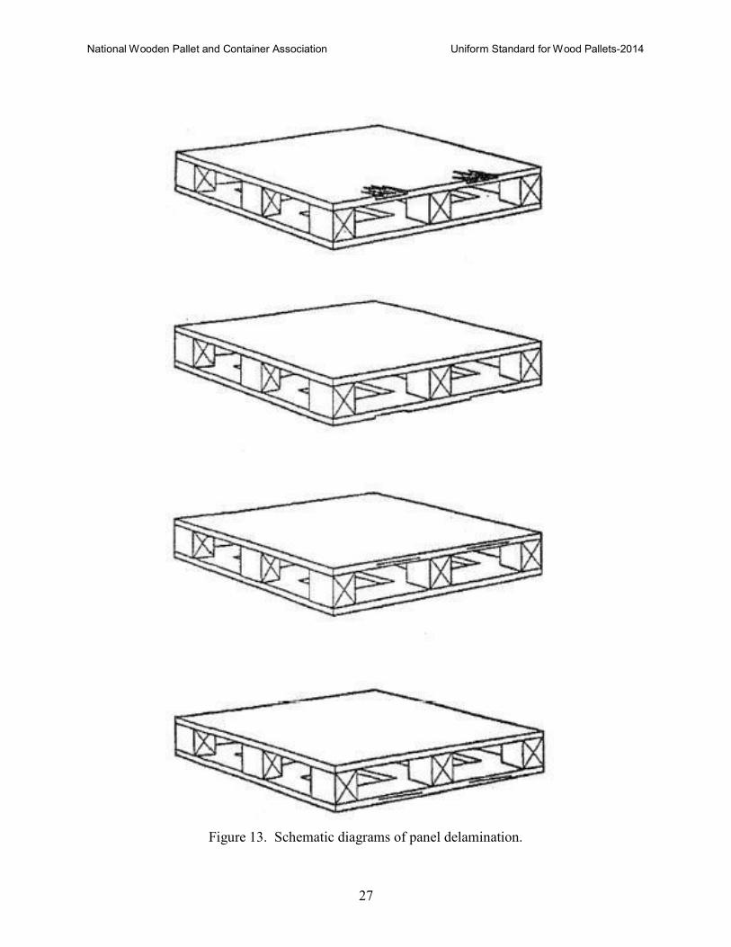
7.1.13 Delamination of panel decks and panel bottom deckboards less than 24 in. (610 mm)
wide (see Figure 13).
Missing wood due to delamination is limited to a maximum of one-third of the panel’s
total thickness for any width panel section and shall not occur in connections.
Delamination is limited to a maximum of 3 in. (76 mm) deep and half the length of the
affected edge or up to 4 in. (104 mm) and two-thirds the length in aggregate on opposite
edges.
7.1.14 Delamination of panel decks and panel bottom deckboards between 24 and 36 in. (610
and 914 mm) wide (see Figure 13).
Delamination is limited to a maximum of 8 in. (203 mm) deep and half the total length of
the affected edge or up to 10 in. (254 mm) and two-thirds the length in aggregate on
opposite edges.
7.1.15 Delamination of panel decks and panel bottom deckboards over 36 in. wide (see Figure
13). Delamination is limited to a maximum of 12 in. (305 mm) deep and half the total
length of the affected edge or up to 15 in. (381 mm) and two-thirds the length in
aggregate on opposite edges.
7.1.16 Delamination around cutouts in panel decks (see Figure 13). In areas around cutouts
where the strong panel axis does not span the openings between the stringers or blocks,
the total delamination cannot exceed 3 in. (76 mm) and one-third the total length on
either or both opposite edges. Otherwise, delamination is limited as in Sections 7.1.13
through 7.1.15.
7.1.17 Block twist, which overhangs pallet sides or ends.
National Wooden Pallet and Container Association Uniform Standard for Wood Pallets-2014
27
Figure 13. Schematic diagrams of panel delamination.
National Wooden Pallet and Container Association Uniform Standard for Wood Pallets-2014
28
7.2 Recommended General Repair Procedures
7.2.1 Pallets of known specification
The repair shall be in accordance with the respective requirements.
7.2.2 Pallets of unknown specification
7.2.2.1 Deckboard/stringerboard/block components
Pallet components with unacceptable damage should be removed and replaced with new or used
components of similar material and dimensions where material quality and tolerances are given
in Section 7.3.
7.2.2.2 Panel Deck Repair
A minimum width of 3-½ in. (89 mm) shall be removed from the entire length or width of a
damaged edge of a panel deck that is to be repaired. The removed section must be replaced by a
butted leading edge lumber deckboard of the same dimensions. For block class pallets, the
blocks that the replacement deckboard is fastened to must be twice as long as the width of the
replacement deckboard or 7 in. (178 mm) minimum, and oriented with this dimension
perpendicular to the replacement deckboard.
An occasional wider or narrower component may be used so long as the gaps between
deckboards are not excessive and that these components are properly fastened.
7.2.2.3 Fastener heads, crowns or points on exposed exterior pallet surfaces shall be driven
flush or below the component surface.
7.2.2.4 Free standing fasteners should be driven into the block, stringer, or stringerboard and
the joints shall be compensated with additional fasteners.
7.2.2.5 Loose components should be removed or securely fastened.
7.2.2.6 Twisted blocks overhanging pallet sides or ends shall be squared and refastened with
at least two fasteners.
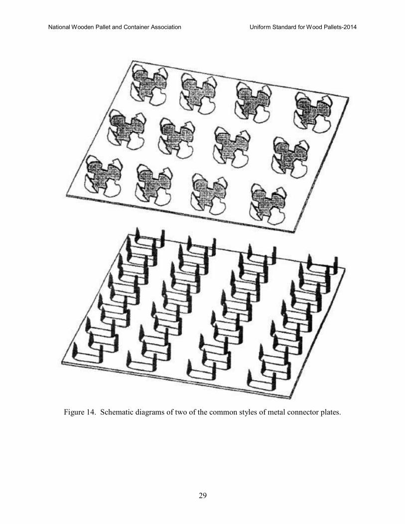
7.2.2.7 Stringers with horizontal or diagonal splits shall be repaired with metal connector
plates (see Figure 14). The only permissible repair of a completely separated part, is
the reattachment of a stringer end foot. Splits at large knows, 1 in. (25 mm) in
diameter, or greater, shall not be repaired. Repair of cross-grain breaks are not
permitted.
National Wooden Pallet and Container Association Uniform Standard for Wood Pallets-2014
29
Figure 14. Schematic diagrams of two of the common styles of metal connector plates.
National Wooden Pallet and Container Association Uniform Standard for Wood Pallets-2014
30
Metal connector plates specifications
Size: Plates shall be a minimum of 2-3/4 in. (70 mm) in length and width and 11 sq. in. (7097
mm2) in area as determined by external plate dimensions.
Material: Minimum basse-metal thickness: 20 gauge (0.034 in.) (0.9 mm) minimum thickness
of uncoated commercial grade sheet steel.
Teeth: At least 4 teeth per sq. in. (645 mm2) of plate area as determined by external
dimensions. The length of teeth shall be at least 0.325 in. (8.3 mm) excluding
plate thickness.
Metal plate application
Apply plates with mechanical, hydraulic, or pneumatic power, using machinery designed and
manufactured for this purpose.
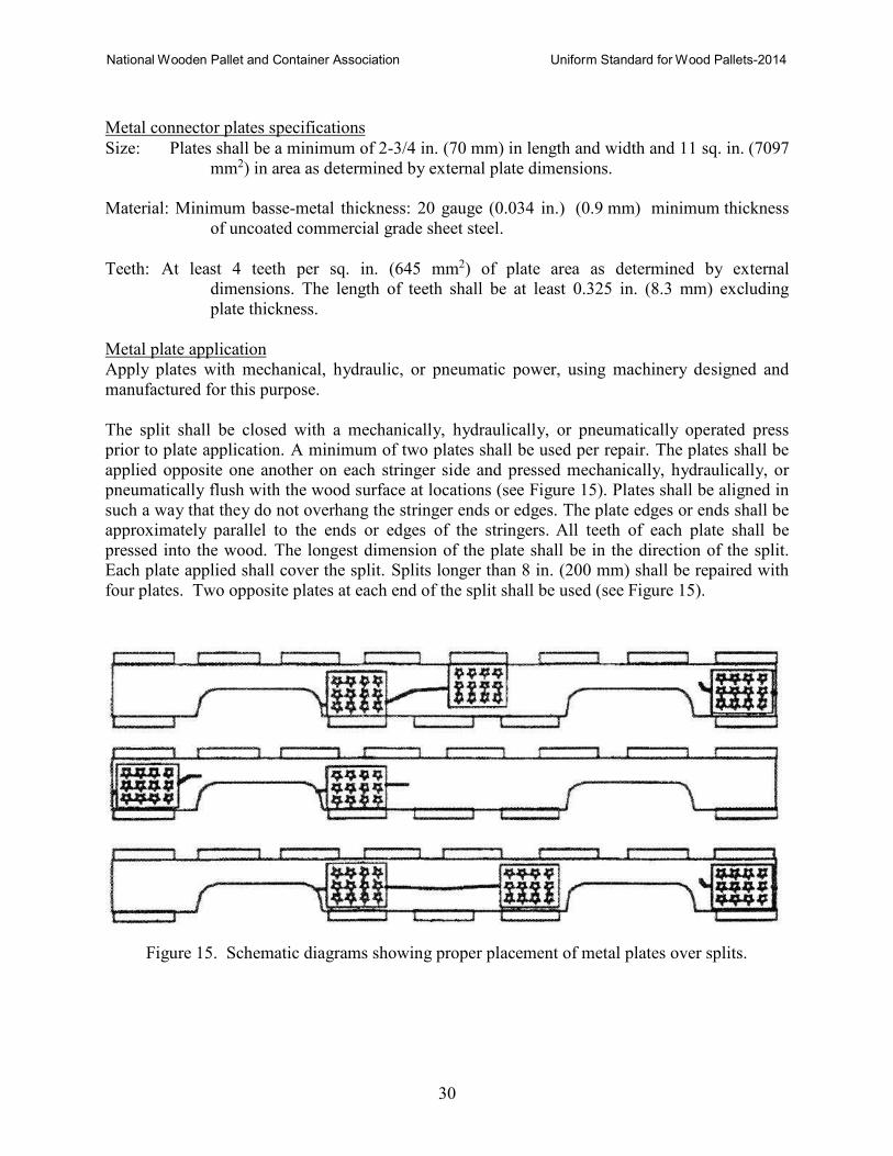
The split shall be closed with a mechanically, hydraulically, or pneumatically operated press
prior to plate application. A minimum of two plates shall be used per repair. The plates shall be
applied opposite one another on each stringer side and pressed mechanically, hydraulically, or
pneumatically flush with the wood surface at locations (see Figure 15). Plates shall be aligned in
such a way that they do not overhang the stringer ends or edges. The plate edges or ends shall be
approximately parallel to the ends or edges of the stringers. All teeth of each plate shall be
pressed into the wood. The longest dimension of the plate shall be in the direction of the split.
Each plate applied shall cover the split. Splits longer than 8 in. (200 mm) shall be repaired with
four plates. Two opposite plates at each end of the split shall be used (see Figure 15).
Figure 15. Schematic diagrams showing proper placement of metal plates over splits.
National Wooden Pallet and Container Association Uniform Standard for Wood Pallets-2014
31
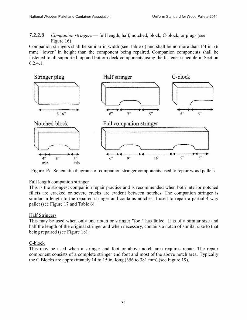
7.2.2.8 Companion stringers — full length, half, notched, block, C-block, or plugs (see
Figure 16)
Companion stringers shall be similar in width (see Table 6) and shall be no more than 1/4 in. (6
mm) “lower” in height than the component being repaired. Companion components shall be
fastened to all supported top and bottom deck components using the fastener schedule in Section
6.2.4.1.
Figure 16. Schematic diagrams of companion stringer components used to repair wood pallets.
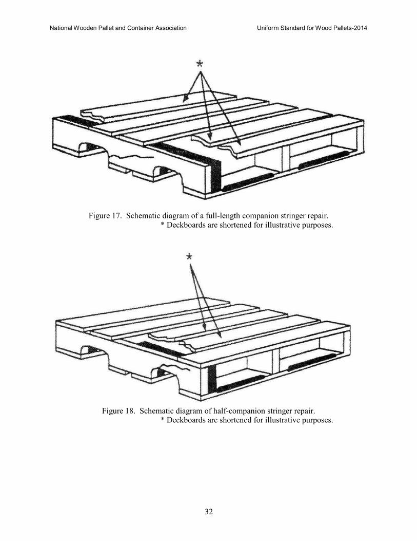
Full length companion stringer
This is the strongest companion repair practice and is recommended when both interior notched
fillets are cracked or severe cracks are evident between notches. The companion stringer is
similar in length to the repaired stringer and contains notches if used to repair a partial 4-way
pallet (see Figure 17 and Table 6).
Half Stringers
This may be used when only one notch or stringer "foot" has failed. It is of a similar size and
half the length of the original stringer and when necessary, contains a notch of similar size to that
being repaired (see Figure 18).
C-block
This may be used when a stringer end foot or above notch area requires repair. The repair
component consists of a complete stringer end foot and most of the above notch area. Typically
the C Blocks are approximately 14 to 15 in. long (356 to 381 mm) (see Figure 19).
National Wooden Pallet and Container Association Uniform Standard for Wood Pallets-2014
32
Figure 17. Schematic diagram of a full-length companion stringer repair.
* Deckboards are shortened for illustrative purposes.
Figure 18. Schematic diagram of half-companion stringer repair.
* Deckboards are shortened for illustrative purposes.
National Wooden Pallet and Container Association Uniform Standard for Wood Pallets-2014
33
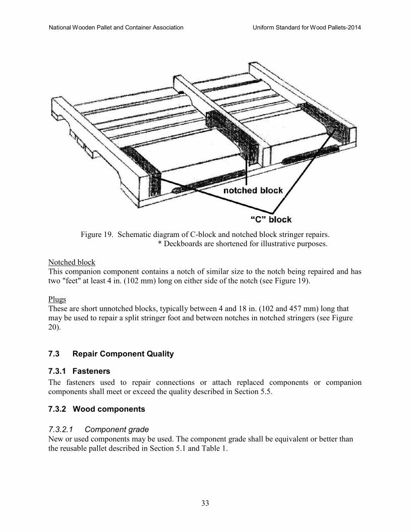
Figure 19. Schematic diagram of C-block and notched block stringer repairs.
* Deckboards are shortened for illustrative purposes.
Notched block
This companion component contains a notch of similar size to the notch being repaired and has
two "feet" at least 4 in. (102 mm) long on either side of the notch (see Figure 19).
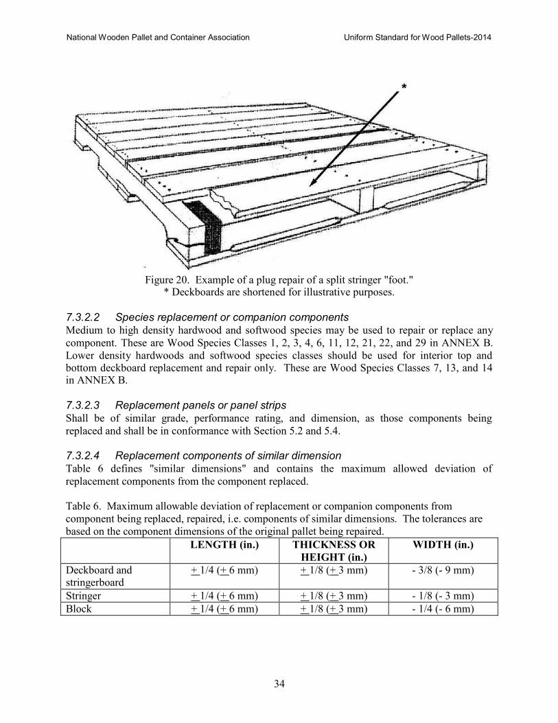
Plugs
These are short unnotched blocks, typically between 4 and 18 in. (102 and 457 mm) long that
may be used to repair a split stringer foot and between notches in notched stringers (see Figure
20).
7.3 Repair Component Quality
7.3.1 Fasteners
The fasteners used to repair connections or attach replaced components or companion
components shall meet or exceed the quality described in Section 5.5.
7.3.2 Wood components
7.3.2.1 Component grade New or used components may be used. The component grade shall be equivalent or better than
the reusable pallet described in Section 5.1 and Table 1.
National Wooden Pallet and Container Association Uniform Standard for Wood Pallets-2014
34
Figure 20. Example of a plug repair of a split stringer "foot."
* Deckboards are shortened for illustrative purposes.
7.3.2.2 Species replacement or companion components Medium to high density hardwood and softwood species may be used to repair or replace any
component. These are Wood Species Classes 1, 2, 3, 4, 6, 11, 12, 21, 22, and 29 in ANNEX B.
Lower density hardwoods and softwood species classes should be used for interior top and bottom deckboard replacement and repair only. These are Wood Species Classes 7, 13, and 14 in ANNEX B.
7.3.2.3 Replacement panels or panel strips Shall be of similar grade, performance rating, and dimension, as those components being
replaced and shall be in conformance with Section 5.2 and 5.4.
7.3.2.4 Replacement components of similar dimension Table 6 defines "similar dimensions" and contains the maximum allowed deviation of
replacement components from the component replaced.
Table 6. Maximum allowable deviation of replacement or companion components from
component being replaced, repaired, i.e. components of similar dimensions. The tolerances are
based on the component dimensions of the original pallet being repaired.
LENGTH (in.) THICKNESS OR
HEIGHT (in.)
WIDTH (in.)
Deckboard and stringerboard
+ 1/4 (+ 6 mm) + 1/8 (+ 3 mm) - 3/8 (- 9 mm)
Stringer + 1/4 (+ 6 mm) + 1/8 (+ 3 mm) - 1/8 (- 3 mm)
Block + 1/4 (+ 6 mm) + 1/8 (+ 3 mm) - 1/4 (- 6 mm)
National Wooden Pallet and Container Association Uniform Standard for Wood Pallets-2014
35
7.4 Repair Workmanship
7.4.1 Flatness
Pallets must be flat and the deckboard thickness within a pallet shall not vary by more than 3/16
in. (5 mm).
7.4.2 Squareness
The difference in diagonal length shall not exceed 1/2 in. (12 mm).
7.4.3 Deckboard spacing
The spacing shall not exceed 4 in. (102 mm) between top deckboards in pallets of unknown
specification.
7.4.4 Overall pallet length and width
The tolerances on pallet length and width for Repaired Pallet Class 1 shall be ± 1/4 in. (± 6 mm) ,
and for Repaired Class 2 or 3 the tolerance ± 1/2 in. (12 mm).
7.4.5 Fastening schedule and placement
In conformance with Sections 6.2.4.1. and 6.2.4.2.
7.4.6 Overall appearance
Sound construction, no deckboards in the notches, components are parallel and perpendicular
and components are flush with the pallet perimeter unless otherwise specified.
7.5 Classes of Repaired 48x40 Notched Three Stringer Pallets
Class 1 - Repaired pallets, shall be permitted to contain metal plates, but no companion stringer
repairs.
Class 2 - Repaired pallets with one or two stringers repaired using plugs and/or notched blocks or
longer companion stringers.
Class 3 - Repaired pallets otherwise not meeting Class 1 and 2 criteria.
7.6 Additional Descriptions for Class of Repaired Pallets
To better balance pallet economy and performance, the above classes may include additional
descriptions such as described below:
GMA Deck Coverage - This implies seven top deckboards and five bottom deckboards. More
top and bottom deckboards better protect product. The pallets are stronger, more functional, and
more durable than pallets with fewer deckboards.
Four- or Six-Inch Wide Endboard - Pallets with nominal 6 in. (152 mm) wide, properly fastened
end deckboards are more functional and durable. Two properly fastened nominal 4 in. (102 mm)
wide endboards, butted together, are equivalent in performance to a single nominal 6 in. (152
mm) properly fastened board.
National Wooden Pallet and Container Association Uniform Standard for Wood Pallets-2014
36
Hardwoods and Softwoods - Repaired pallets of the same design fabricated predominantly with
dense hardwoods will be more durable and stronger than pallets of a similar design fabricated
predominantly with softwood species.
Stringers Repaired with Metal Connector Plates - Notched stringers repaired using metal
connector plates, in accordance with procedures described in this Standard, have been shown to
restore the stringer to its original strength.
7.7 Marking
The recommended marking should include:
− Class of repair
− Repairer’s identification
− Date of repair
− Owner identification (if applicable, and for pallets of known specification)
Space permitting, the mark shall be a minimum of 2 in. (51 mm) high, with letters 1 in. (25 mm)
high.
8 REMANUFACTURE OF PALLETS
The remanufacture of a pallet using recycled pallet parts is an environmentally conscientious
practice, which also increases unit load efficiency, and reduces the cost of product storage and
distribution. All pallets should be removed from service and be remanufactured, recycled or
properly disposed of, if determined to be unsafe to persons or goods.
8.1 Quality of Parts
8.1.2 Fasteners
The fasteners used for the assembly of remanufactured pallets shall meet or exceed the quality
criteria described in Section 5.5. Combo pallets containing new stringers or blocks shall be
assembled using fasteners, which meet or exceed the criteria for "Manufacture of Pallets.”
Pallets assembled with recycled stringers or blocks shall be assembled using fasteners meeting or
exceeding the criteria for "Repair of Pallets."
8.1.2 New wood parts
The quality of new wood parts for use in remanufactured pallets shall conform to Sections 5.1,
5.2, 5.3 and 5.4.
8.1.3 Quality of recycled pallet parts
8.1.3.1 Recycled component grades Recycled components shall conform to the quality criteria in Sections 5.1, 5.2, 5.3 and 5.4.
National Wooden Pallet and Container Association Uniform Standard for Wood Pallets-2014
37
8.2.3.2 Wood species The wood species used in remanufactured pallets is not limited. However, suggested groupings
of wood species of practical value during sortation are listed Table 7. The wood species in each
wood species class can be found in ANNEX B.
Table 7. Wood Species Groups.
WOOD GROUP WOOD SPECIES CLASSES CONTAINED IN GROUP
Medium/High density woods All species listed in Species Classes 1, 2, 3, 4, 11, 21, 22
Low density woods All species listed in Species Classes 6, 7, 12, 13, 14, 29
Hardwoods All species listed in Species Classes 1, 2, 3, 4, 6, 7, 21, 29
Softwoods All species listed in Species Classes 11, 12, 13, 14, 22
Mixed woods All species listed for other wood groups
8.2 Quality of Assembly
Quality of assembly of remanufactured pallets shall be according to Section 6, with the following
exceptions and additions.
8.2.1 Driving fasteners
Driving fasteners through existing fastener holes in recycled pallet components shall be avoided.
8.2.2 Pre-existing fastener holes
Pre-existing fastener holes shall be positioned during assembly so as to limit their impact on
pallet performance. This includes positioning such holes near but not within connections.
8.2.3 Fastener cause splits
Not more than one half of the components in a reassembled pallet shall contain open splits with
visible fastener shanks or legs.
8.2.4 Recycled component dimensional variation
Recycled component dimensional variation within each remanufactured pallet, relative to the
target dimension (see Table 8).
Table 8. Dimension Tolerances of Components.
COMPONENT DIMENSION TOLERANCE
Board Thickness -0 +1/8” (-0 +3 mm)
Board Width +unlimited – ¼” (-6 mm)*
Board Length +¼” (+6 mm)
Stringer Height -0 +1/8” (-0 +3 mm)
Stringer Width -0 +¼” (-0 +6 mm)
Stringer Length +¼” (+6 mm)
Block Height -0 +1/8” (-0 +3 mm)
Block Width -0 +¼” (-0 +6 mm)
Block Length +¼” (+6 mm)

National Wooden Pallet and Container Association Uniform Standard for Wood Pallets-2014
38
* for each nominal deckboard width
National Wooden Pallet and Container Association Uniform Standard for Wood Pallets-2014
39
PART II PERFORMANCE STANDARD
9 CONDITIONS OF PALLET USE
The use conditions which pallets shall sustain during unit load material handling vary.
Therefore, the conditions of use shall be specified, including performance levels. Where
conditions of use vary, the condition which results in the highest stress levels shall be used as a
basis for determining performance.
9.1 Load Condition
Provide the description of the packages, containers or units to be placed on the pallet (i.e. bags,
boxes, barrels, bulk containers, blocks and machinery including the use of load stabilizers).
Provide measurements and location of bearing areas for the packages, containers or units to be
placed on the pallet and the pallet top and bottom decks, stringers or blocks.
Provide maximum and average load levels and load level variations.
9.2 Support Conditions
Indicate maximum unsupported free span along the pallet length and width.
Indicate maximum number of unit loads in a stack.
Indicate measurements and locations of bearing areas between the pallet stringers or
stringerboards and top and bottom decks and their supports.
10 MEASURES OF PALLET PERFORMANCE
Pallet performance shall be specified in terms of strength, stiffness and durability. Pallet
performance is directly correlated to the type and quality of fastener, grade, species, and moisture
content of lumber components and the material handling environment.
Strength - determine design or safe working loads for each condition of use. When reusable
pallet conditions exist, the pallet and pallet component performance shall be based on the
minimum design or safe working load.
Stiffness - determine maximum deflection or pallets and pallet components for each condition of
use.
Durability - Single-use or Reusable categories (see Section 4.2).
Single-use pallets are intended for use with a single unit load. This category of pallets requires
sufficient damage resistance to survive at least one trip without requiring repair.
Reusable pallets are intended for repeated uses for more than one unit load. This category of
pallets requires sufficient damage resistance to survive multiple trips without requiring repair.
National Wooden Pallet and Container Association Uniform Standard for Wood Pallets-2014
40
The criteria for the classification of pallets are given in the documentation of the test procedures
provided in Section 11.
11 TEST PROCEDURES
11.1 Testing for Physical Models or Prototypes
When possible, actual loads and supports shall be used in the test. However, load and support
analogs, based on sound engineering principles, are acceptable. The following test methods and
their design criteria are recognized:
ISO 8611 series. Pallets for materials handling – Flat pallets
International Standards Organization (ISO)
www.iso.org
ASTM D1185. "Standard Test Methods for Pallets and Related Structures Employed in Material
Handling and Shipping."
ASTM International
www.astm.org
11.2 Testing of Computer Models
The computer software for predicting pallet performance is the Pallet Design System© (PDS)5.
5 The Pallet Design System (PDS) can be used for designing, selecting and predicting the performance of wood
pallets. PDS is available through: NWPCA, www.palletcentral.com
National Wooden Pallet and Container Association Uniform Standard for Wood Pallets-2014
41
PART III PHYTOSANITATION STANDARD
12 PHYTOSANITATION OF WOOD PALLETS
Treatment and marking of wood pallets must conform to the International Standards for
Phytosanitary Measures Publication No. 15 (ISPM 15) Regulations of wood packaging material
in international trade. ISPM 15 has been adopted by the United States and its trading partners as
their import requirements for wood pallets.
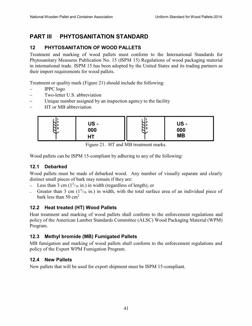
Treatment or quality mark (Figure 21) should include the following:
− IPPC logo
− Two-letter U.S. abbreviation
− Unique number assigned by an inspection agency to the facility
− HT or MB abbreviation
Figure 21. HT and MB treatment marks.
Wood pallets can be ISPM 15-compliant by adhering to any of the following:
12.1 Debarked
Wood pallets must be made of debarked wood. Any number of visually separate and clearly
distinct small pieces of bark may remain if they are:
− Less than 3 cm (13/16 in.) in width (regardless of length), or
− Greater than 3 cm (13/16 in.) in width, with the total surface area of an individual piece of
bark less than 50 cm2
12.2 Heat treated (HT) Wood Pallets
Heat treatment and marking of wood pallets shall conform to the enforcement regulations and
policy of the American Lumber Standards Committee (ALSC) Wood Packaging Material (WPM)
Program.
12.3 Methyl bromide (MB) Fumigated Pallets
MB fumigation and marking of wood pallets shall conform to the enforcement regulations and
policy of the Export WPM Fumigation Program.
12.4 New Pallets
New pallets that will be used for export shipment must be ISPM 15-compliant.

National Wooden Pallet and Container Association Uniform Standard for Wood Pallets-2014
42
12.5 Recycled Pallets
Reusing ISPM 15-compliant wood pallets do not require retreatment and remarking. However,
repaired, remanufactured and combo pallets must be retreated and remarked in order to be ISPM
15-compliant. Old marks must be obliterated.
National Wooden Pallet and Container Association Uniform Standard for Wood Pallets-2014
43
ANNEX A
STANDARDS CONCERNING WOOD PALLETS AND CONTAINERS
National Wooden Pallet and Container Association (NWPCA) www.palletcentral.com
− NWPCA Uniform Standard for Wood Pallets
− NWPCA Uniform Standard for Wood Containers
Material Handling Industry of America (MHIA) www.mhia.org
− MH1 Pallets, Slip Sheets, and Other Bases For Unit Loads (2005 edition)
• Part 1 Definitions and Terminology Covering Pallets and Related Structures • Part 2 Sizes of Wood Pallets
• Part 3 Wood Pallets
• Part 4 Export Pallets
• Part 5 Driven Fasteners for Assembly of Pallets and Related Structures
• Part 6 Protocol for Measuring Quality of Pallet Nails and Staples
• Part 7 Testing Procedures for Pallets and Related Structures
• Part 8 Slip Sheets
• Part 9 Wood Pallets for Military Use
• Part 10 Performance Specification for Pallets to be Used in Automated Unit-Load
Material Handling Equipment
ASTM International www.astm.org D10 Packaging
− ASTM D1185 Standard Test Methods for Pallets and Related Structures Employed in
Material Handling and Shipping
− ASTM D4169 Standard Practice for Performance Testing of Shipping Containers and
Systems
− ASTM D6055 Standard Test Methods for Mechanical Handling of Unitized Loads and
Large Shipping Cases and Crates
− ASTM D6179 Standard Test Methods for Rough Handling of Unitized Loads and Large
Shipping Cases and Crates
− ASTM D6198 Standard Guide for Transport Packaging Design
− ASTM D6199 Standard Practice for Quality of Wood Members of Containers and Pallets
− ASTM D6253 Standard Practice for Treatment and/or Marking of Wood Packaging
Materials
F16 Fasteners
− ASTM F680 Standard Test Methods for Nails
− ASTM F1575 Standard Test Method for Determining Bending Yield Moment of Nails
− ASTM F1667 Standard Specification for Driven Fasteners: Nails, Spikes, and Staples
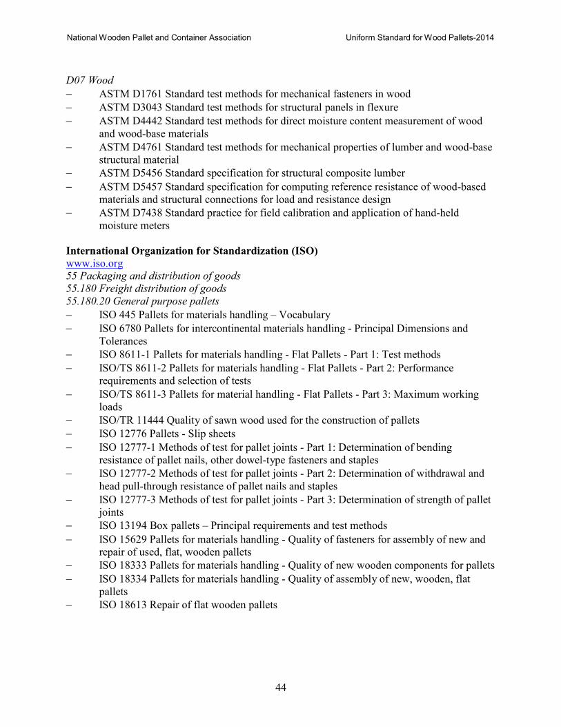
National Wooden Pallet and Container Association Uniform Standard for Wood Pallets-2014
44
D07 Wood
− ASTM D1761 Standard test methods for mechanical fasteners in wood
− ASTM D3043 Standard test methods for structural panels in flexure
− ASTM D4442 Standard test methods for direct moisture content measurement of wood
and wood-base materials
− ASTM D4761 Standard test methods for mechanical properties of lumber and wood-base
structural material
− ASTM D5456 Standard specification for structural composite lumber
− ASTM D5457 Standard specification for computing reference resistance of wood-based
materials and structural connections for load and resistance design
− ASTM D7438 Standard practice for field calibration and application of hand-held
moisture meters
International Organization for Standardization (ISO) www.iso.org 55 Packaging and distribution of goods
55.180 Freight distribution of goods
55.180.20 General purpose pallets
− ISO 445 Pallets for materials handling – Vocabulary
− ISO 6780 Pallets for intercontinental materials handling - Principal Dimensions and
Tolerances
− ISO 8611-1 Pallets for materials handling - Flat Pallets - Part 1: Test methods
− ISO/TS 8611-2 Pallets for materials handling - Flat Pallets - Part 2: Performance
requirements and selection of tests
− ISO/TS 8611-3 Pallets for material handling - Flat Pallets - Part 3: Maximum working
loads
− ISO/TR 11444 Quality of sawn wood used for the construction of pallets
− ISO 12776 Pallets - Slip sheets
− ISO 12777-1 Methods of test for pallet joints - Part 1: Determination of bending
resistance of pallet nails, other dowel-type fasteners and staples
− ISO 12777-2 Methods of test for pallet joints - Part 2: Determination of withdrawal and
head pull-through resistance of pallet nails and staples
− ISO 12777-3 Methods of test for pallet joints - Part 3: Determination of strength of pallet
joints
− ISO 13194 Box pallets – Principal requirements and test methods
− ISO 15629 Pallets for materials handling - Quality of fasteners for assembly of new and
repair of used, flat, wooden pallets
− ISO 18333 Pallets for materials handling - Quality of new wooden components for pallets
− ISO 18334 Pallets for materials handling - Quality of assembly of new, wooden, flat
pallets
− ISO 18613 Repair of flat wooden pallets
National Wooden Pallet and Container Association Uniform Standard for Wood Pallets-2014
45
International Plant Protection Convention (IPPC) www.ippc.int
− International Standard for Phytosanitary Measures (ISPM) Publication No. 15 Regulation
for wood packaging material in international trade
American Society of Mechanical Engineers (ASME) www.asme.org
− ASME B1.1 Unified inch screw threads (UN and UNR thread form)
− ASME B18.2.1 Square, hex, heavy hex and askew head bolts and hex, heavy hex, hex flange,
− lobed head and lag screws (inch series)
− ASME B18.6.1 Wood screws, inch series
National Institute of Standards and Technology (NIST) www.nist.gov
− PS 1-07 Structural Plywood
− PS 2-04 Performance Standard for Wood-Based Structural-Use Panels
− PS 20-05 American Softwood Lumber Standard
APA – The Engineered Wood Association www.apawood.org
− PRP 108 Performance Standards and Policies for Structural-Use Panels
Hardwood Plywood and Veneer Association (HPVA) www.hpva.org
− ANSI/HPVA HP-1-2004 American National Standard for Hardwood and Decorative
Plywood
National Hardwood Lumber Association (NHLA) www.natlhardwood.org
− Rules for the measurement and inspection of hardwood and cypress

National Wooden Pallet and Container Association Uniform Standard for Wood Pallets-2014
46
SPECIFICATIONS CONCERNING WOOD PALLETS AND CONTAINERS
North America
American Society of Agricultural and Biological Engineers (ASABE) www.asabe.org
− Agricultural pallet bins (ASAE S337.1)
APA - The Engineered Wood Association www.apawood.org
− Softwood plywood pallets PP 61-80
− Collapsible big bin
− Collapsible slim bin
ASTM International www.astm.org D10 Packaging
− ASTM D6039/D6039M Standard Specification Open and Covered Wood Crates
− ASTM D6251/D6251M Standard Specification for Wood-Cleated Panelboard Shipping
Boxes
− ASTM D6254/D6254M Standard Specification for Wirebound Pallet-Type Wood Boxes
− ASTM D6256/D6256M Standard Specification for Wood-Cleated Shipping Boxes and
Skidded, Load-Bearing Bases
− ASTM D6573/D6573M Standard Specification for General Purpose Wirebound Shipping
Boxes
− ASTM D6880 Standard Specification for Wood Boxes
− ASTM D7478/D7478M Standard Specification for Heavy Duty Sheathed Wood Crates
Canadian Pallet Council (CPC) www.cpcpallet.com
− 48x40 in. stringer pallet
Committee for Graphics Arts Technology Standards (CGATS)
− Graphic technology - Pallet loading for printed materials (1995)
The Electronic Industry Pallet Specification (EIPS) Task Group
www.hp.com/packaging/EIPS/
− Electronic Industry Pallet Specification, 2003
Grocery Manufacturers Association of America (GMA) www.gmabrands.com
− Recommendations on the Grocery Industry Pallet System (1992)

National Wooden Pallet and Container Association Uniform Standard for Wood Pallets-2014
47
Department of Defense www.assist.daps.dla.mil/quicksearch
− A-A-52586 Pallet, material handling, wood stringer construction, 4-way partial, 48 x 40
inches
− MIL-C-3774B Crates, Wood: Open 12,000 and 16,000-Pound Capacity
− MIL-DTL-2427H Box, Ammunition Packing: Wood, nailed
− MIL-C-3774B Crates, Wood: Open 12,000- and 16,000-pound capacity
− MIL-C-21215A(1) NOT 1 Crates, Pallets, Ammunition
− MIL-P-15011J Pallet, Material Handling, Wood Post Construction, 4-Way Entry
− MIL-P-15943D(5) Pallet, material handling, wood, ship cargo, stevedoring, 48 inches
long by 72 inches wide, 2-way entry
− MIL-P-45449B Pallets, units, wood, for shipment of projectile metal parts, and projectile
ammunition
− MIL-P-87089 Pallets, material handling, molded wood particles 40 x 48 inch, 4-way
− MIL-STD-147 Palletized Unit Loads
− MIL-STD-299 Visual inspection standards for nailed wood boxes and wirebound wood
boxes used in small arms ammunition
− QSTAG-880 ED.1 Military pallets, packages and containers
− STANAG-2828 ED.6 Military pallet, packages and containers
European Union
Association of Plastic Manufacturers in Europe (APME)
www.apme.org Chemical Industry (CP) Pallets
− CP1 1000x1200 mm
− CP2 800x1200 mm
− CP3 1140x1140 mm
− CP4 1100x1300 mm
− CP5 760x1140 mm
− CP6 1200x1000 mm
− CP7 1300x1100 mm
− CP8 1140x1140 mm
− CP9 1140x1140 mm
Pallet Return System (PRS) Pallets
− PRS 4 1100x1300 mm
− PRS 7 1300x1100 mm
− PRS 8 1140x1140 mm
− PRS 9 1140x1140 mm
National Wooden Pallet and Container Association Uniform Standard for Wood Pallets-2014
48
European Pallet Association (EPAL) www.epal.eu
− 800 x 1200 mm EUR
− 1200 x 1000 mm EUR 2
− 1000 x 1200mm EUR 3
− 800 x 600 mm EUR 6
− Box pallets
− Pallet collars
− 1100 x 1100mm (T11)
Asia
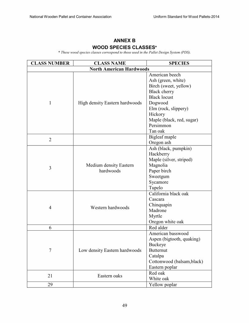
National Wooden Pallet and Container Association Uniform Standard for Wood Pallets-2014
49
ANNEX B
WOOD SPECIES CLASSES* * These wood species classes correspond to those used in the Pallet Design System (PDS).
CLASS NUMBER CLASS NAME SPECIES
North American Hardwoods
1
High density Eastern hardwoods
American beech Ash (green, white)
Birch (sweet, yellow)
Black cherry
Black locust
Dogwood
Elm (rock, slippery)
Hickory
Maple (black, red, sugar)
Persimmon
Tan oak
2 Bigleaf maple
Oregon ash
3
Medium density Eastern
hardwoods
Ash (black, pumpkin) Hackberry
Maple (silver, striped)
Magnolia
Paper birch
Sweetgum
Sycamore
Tupelo
4
Western hardwoods
California black oak Cascara
Chinquapin
Madrone
Myrtle
Oregon white oak
6 Red alder
7
Low density Eastern hardwoods
American basswood Aspen (bigtooth, quaking)
Buckeye
Butternut
Catalpa
Cottonwood (balsam,black)
Eastern poplar
21
Eastern oaks Red oak White oak
29 Yellow poplar
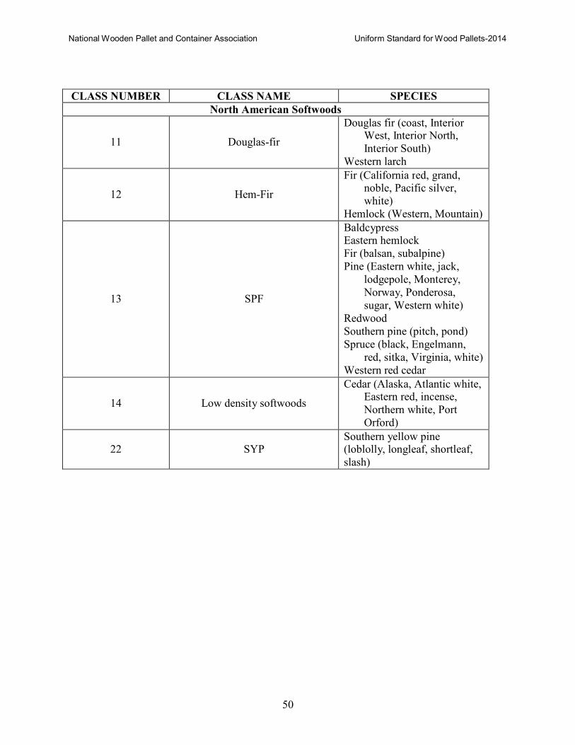
National Wooden Pallet and Container Association Uniform Standard for Wood Pallets-2014
50
CLASS NUMBER CLASS NAME SPECIES
North American Softwoods
11
Douglas-fir
Douglas fir (coast, Interior West, Interior North,
Interior South)
Western larch
12
Hem-Fir
Fir (California red, grand, noble, Pacific silver,
white)
Hemlock (Western, Mountain)
13
SPF
Baldcypress Eastern hemlock
Fir (balsan, subalpine)
Pine (Eastern white, jack,
lodgepole, Monterey,
Norway, Ponderosa,
sugar, Western white)
Redwood
Southern pine (pitch, pond)
Spruce (black, Engelmann,
red, sitka, Virginia, white)
Western red cedar
14
Low density softwoods
Cedar (Alaska, Atlantic white, Eastern red, incense,
Northern white, Port
Orford)
22
SYP Southern yellow pine (loblolly, longleaf, shortleaf,
slash)
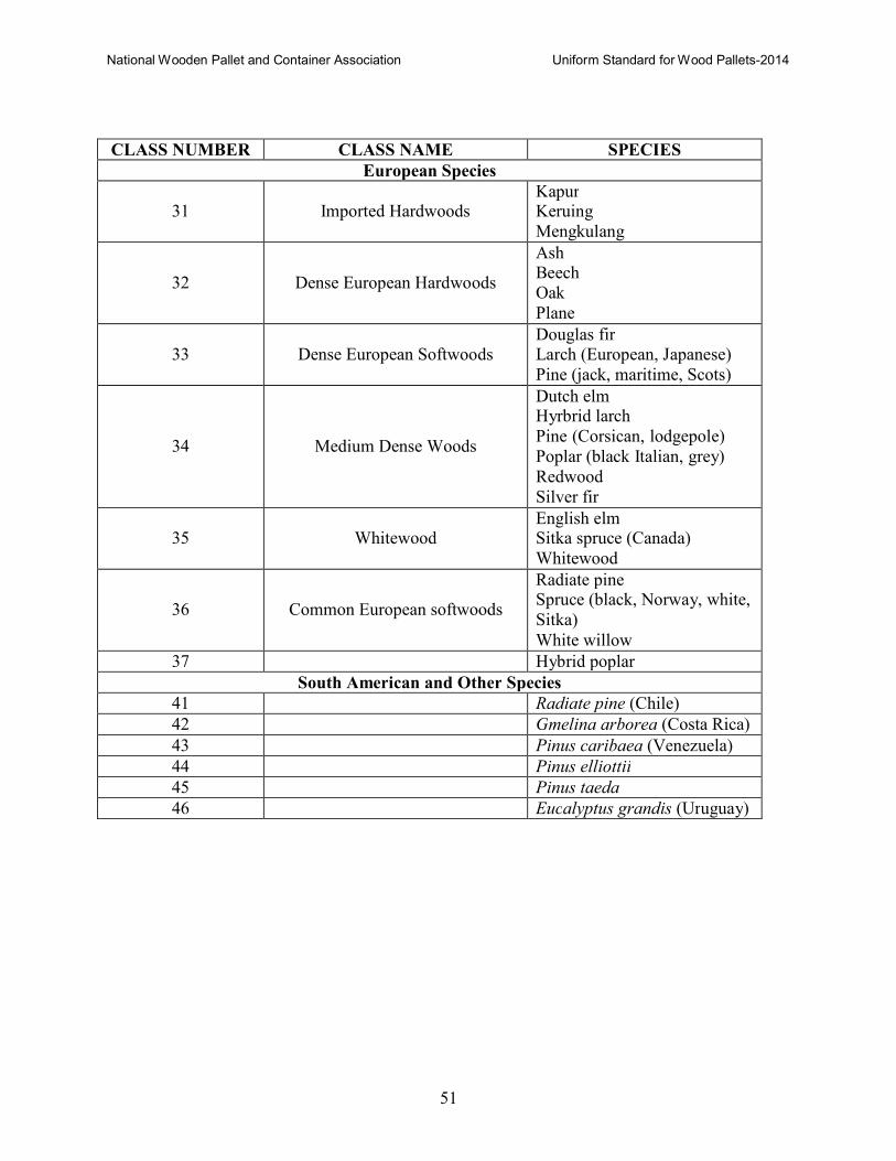
National Wooden Pallet and Container Association Uniform Standard for Wood Pallets-2014
51
CLASS NUMBER CLASS NAME SPECIES
European Species
31
Imported Hardwoods Kapur Keruing
Mengkulang
32
Dense European Hardwoods
Ash Beech
Oak
Plane
33
Dense European Softwoods Douglas fir Larch (European, Japanese)
Pine (jack, maritime, Scots)
34
Medium Dense Woods
Dutch elm Hyrbrid larch
Pine (Corsican, lodgepole)
Poplar (black Italian, grey)
Redwood
Silver fir
35
Whitewood English elm Sitka spruce (Canada)
Whitewood
36
Common European softwoods
Radiate pine Spruce (black, Norway, white,
Sitka)
White willow
37 Hybrid poplar
South American and Other Species
41 Radiate pine (Chile)
42 Gmelina arborea (Costa Rica)
43 Pinus caribaea (Venezuela)
44 Pinus elliottii
45 Pinus taeda
46 Eucalyptus grandis (Uruguay)
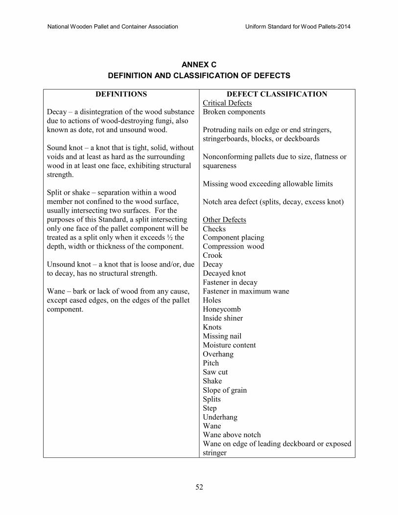
National Wooden Pallet and Container Association Uniform Standard for Wood Pallets-2014
52
ANNEX C
DEFINITION AND CLASSIFICATION OF DEFECTS
DEFINITIONS
Decay – a disintegration of the wood substance
due to actions of wood-destroying fungi, also
known as dote, rot and unsound wood.
Sound knot – a knot that is tight, solid, without
voids and at least as hard as the surrounding
wood in at least one face, exhibiting structural
strength.
Split or shake – separation within a wood
member not confined to the wood surface,
usually intersecting two surfaces. For the
purposes of this Standard, a split intersecting
only one face of the pallet component will be
treated as a split only when it exceeds ½ the
depth, width or thickness of the component.
Unsound knot – a knot that is loose and/or, due
to decay, has no structural strength.
Wane – bark or lack of wood from any cause,
except eased edges, on the edges of the pallet
component.
DEFECT CLASSIFICATION Critical Defects Broken components
Protruding nails on edge or end stringers,
stringerboards, blocks, or deckboards
Nonconforming pallets due to size, flatness or
squareness
Missing wood exceeding allowable limits
Notch area defect (splits, decay, excess knot)
Other Defects
Checks Component placing
Compression wood
Crook
Decay
Decayed knot
Fastener in decay
Fastener in maximum wane
Holes
Honeycomb
Inside shiner
Knots
Missing nail
Moisture content
Overhang
Pitch
Saw cut
Shake
Slope of grain
Splits
Step
Underhang Wane Wane above notch
Wane on edge of leading deckboard or exposed
stringer
National Wooden Pallet and Container Association Uniform Standard for Wood Pallets-2014
53
ANNEX D
GRADING AGENCIES FOR STRUCTURAL PANELS
APA - The Engineered Wood Association
www.apawaood.org
Professional Service Industries/Pittsburgh Testing Laboratories
www.psiusa.com/services/wood.aspx?
Timber Engineering Company (TECO)
www.tecotested.com
National Wooden Pallet and Container Association Uniform Standard for Wood Pallets-2014
54
ANNEX E
WOOD-BASED COMPOSITE TESTS
E1. 24-hour Composite Block Soak Test
E1.1 Samples • Ten (10) blocks (minimum) are required. • Condition each block at ambient laboratory conditions for at least 48 hrs. prior to testing.
E1.2 Test equipment • An appropriately sized open-top flat-bottom water tight tank capable of being filled to a
depth of at least 12 inches. If required, more than one tank can be used.
• A suitable “hold down” fixture(s) to prevent the blocks from floating and to maintain a
constant water hydraulic pressure of 0.2 psi at the top surface of the block.
− The hold-down fixture may be suspended from above or placed into the tank.
− The fixture should be designed to allow water free access to all block surfaces.
− The fixture should be designed so that when submerged, the bottom of the block is at
least 1” above the bottom of the tank and 5.5 inches (+/- .25) below the surface level of
the water (providing a hydraulic pressure of .20 psi).
E1.3 Procedures • Measure and record each block’s weight, length, width and height. • Dimensional measurements are to be made using a surface plate and digital height gage
capable of measuring to an accuracy of +/- .001 in.
• Each dimension should be measured at three different locations on the block, with the
location of the measurement marked for future reference.
• Place the blocks into the tank such that:
− blocks are oriented bottom (smooth) side up.
− water temperature should be maintained between 65 and 75°F.
− blocks are separated by at least 1 in. (25 mm)
• Blocks should be submerged for a minimum of 24 hours • Remove blocks and allow to drain on an open grate.
• Final measurements should be made within 5 min. of removal from the tank.
E1.4 Measurements • Measure the after-soak weight, length, width and height of each block. • Measure dimensions at the same points as measured before.
• Calculate and report results as follows:
− % change = (wet - dry) / dry x 100.
− Average % and standard deviation of water-weight gain.
− Average % and standard deviation for each dimensional change.
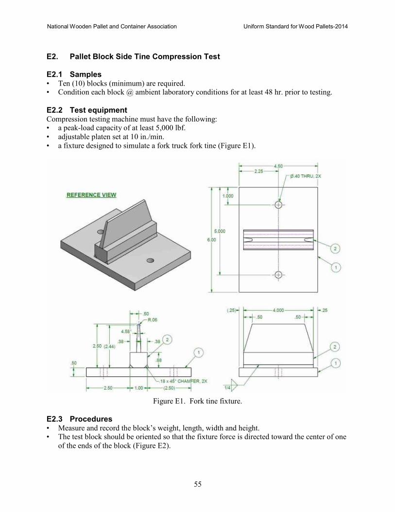
National Wooden Pallet and Container Association Uniform Standard for Wood Pallets-2014
55
E2. Pallet Block Side Tine Compression Test
E2.1 Samples • Ten (10) blocks (minimum) are required. • Condition each block @ ambient laboratory conditions for at least 48 hr. prior to testing.
E2.2 Test equipment Compression testing machine must have the following: • a peak-load capacity of at least 5,000 lbf.
• adjustable platen set at 10 in./min.
• a fixture designed to simulate a fork truck fork tine (Figure E1).
Figure E1. Fork tine fixture.
E2.3 Procedures • Measure and record the block’s weight, length, width and height. • The test block should be oriented so that the fixture force is directed toward the center of one
of the ends of the block (Figure E2).
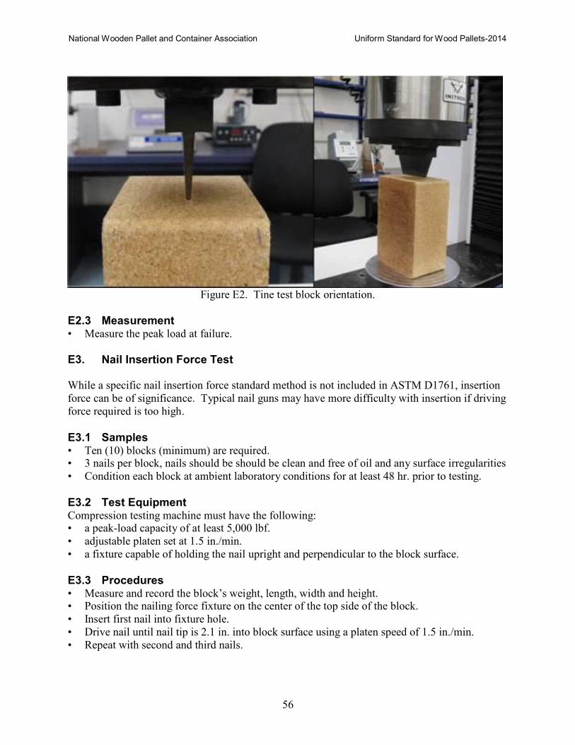
National Wooden Pallet and Container Association Uniform Standard for Wood Pallets-2014
56
Figure E2. Tine test block orientation.
E2.3 Measurement • Measure the peak load at failure.
E3. Nail Insertion Force Test
While a specific nail insertion force standard method is not included in ASTM D1761, insertion
force can be of significance. Typical nail guns may have more difficulty with insertion if driving
force required is too high.
E3.1 Samples • Ten (10) blocks (minimum) are required. • 3 nails per block, nails should be should be clean and free of oil and any surface irregularities
• Condition each block at ambient laboratory conditions for at least 48 hr. prior to testing.
E3.2 Test Equipment Compression testing machine must have the following: • a peak-load capacity of at least 5,000 lbf.
• adjustable platen set at 1.5 in./min.
• a fixture capable of holding the nail upright and perpendicular to the block surface.
E3.3 Procedures • Measure and record the block’s weight, length, width and height. • Position the nailing force fixture on the center of the top side of the block.
• Insert first nail into fixture hole.
• Drive nail until nail tip is 2.1 in. into block surface using a platen speed of 1.5 in./min.
• Repeat with second and third nails.
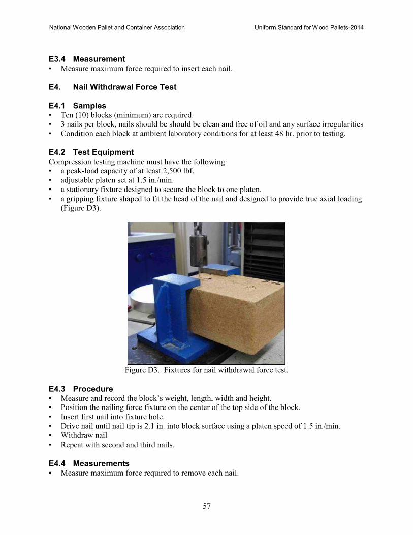
National Wooden Pallet and Container Association Uniform Standard for Wood Pallets-2014
57
E3.4 Measurement • Measure maximum force required to insert each nail.
E4. Nail Withdrawal Force Test
E4.1 Samples • Ten (10) blocks (minimum) are required. • 3 nails per block, nails should be should be clean and free of oil and any surface irregularities
• Condition each block at ambient laboratory conditions for at least 48 hr. prior to testing.
E4.2 Test Equipment Compression testing machine must have the following: • a peak-load capacity of at least 2,500 lbf.
• adjustable platen set at 1.5 in./min.
• a stationary fixture designed to secure the block to one platen.
• a gripping fixture shaped to fit the head of the nail and designed to provide true axial loading
(Figure D3).
Figure D3. Fixtures for nail withdrawal force test.
E4.3 Procedure • Measure and record the block’s weight, length, width and height. • Position the nailing force fixture on the center of the top side of the block.
• Insert first nail into fixture hole.
• Drive nail until nail tip is 2.1 in. into block surface using a platen speed of 1.5 in./min.
• Withdraw nail
• Repeat with second and third nails.
E4.4 Measurements • Measure maximum force required to remove each nail.
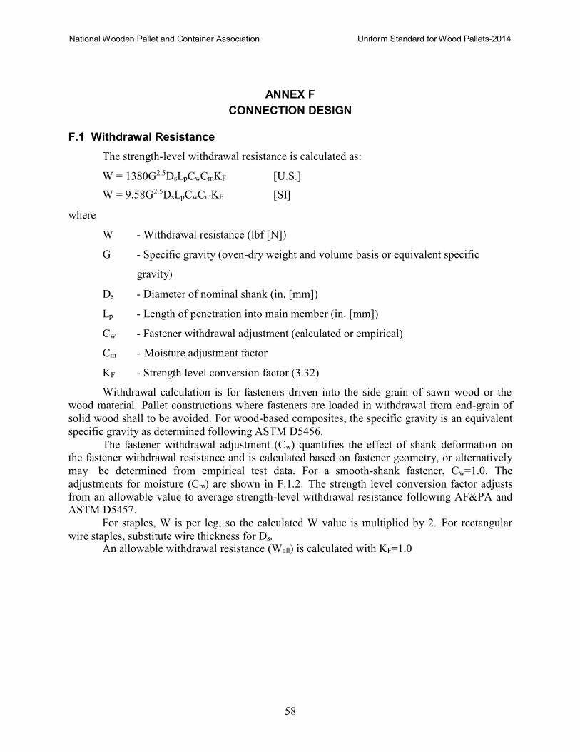
National Wooden Pallet and Container Association Uniform Standard for Wood Pallets-2014
58
ANNEX F
CONNECTION DESIGN
F.1 Withdrawal Resistance
The strength-level withdrawal resistance is calculated as:
W = 1380G2.5DsLpCwCmKF [U.S.]
W = 9.58G2.5DsLpCwCmKF [SI]
where
W - Withdrawal resistance (lbf [N])
G - Specific gravity (oven-dry weight and volume basis or equivalent specific
gravity)
Ds - Diameter of nominal shank (in. [mm])
Lp - Length of penetration into main member (in. [mm])
Cw - Fastener withdrawal adjustment (calculated or empirical)
Cm - Moisture adjustment factor
KF - Strength level conversion factor (3.32)
Withdrawal calculation is for fasteners driven into the side grain of sawn wood or the
wood material. Pallet constructions where fasteners are loaded in withdrawal from end-grain of
solid wood shall to be avoided. For wood-based composites, the specific gravity is an equivalent
specific gravity as determined following ASTM D5456.
The fastener withdrawal adjustment (Cw) quantifies the effect of shank deformation on
the fastener withdrawal resistance and is calculated based on fastener geometry, or alternatively
may be determined from empirical test data. For a smooth-shank fastener, Cw=1.0. The
adjustments for moisture (Cm) are shown in F.1.2. The strength level conversion factor adjusts
from an allowable value to average strength-level withdrawal resistance following AF&PA and
ASTM D5457.
For staples, W is per leg, so the calculated W value is multiplied by 2. For rectangular
wire staples, substitute wire thickness for Ds. An allowable withdrawal resistance (Wall) is calculated with KF=1.0
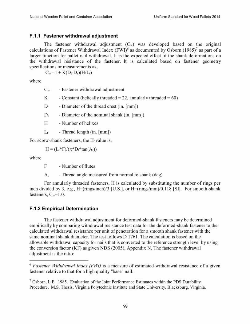
National Wooden Pallet and Container Association Uniform Standard for Wood Pallets-2014
59
F.1.1 Fastener withdrawal adjustment
The fastener withdrawal adjustment (Cw) was developed based on the original
calculations of Fastener Withdrawal Index (FWI)6 as documented by Osborn (1985)7 as part of a
larger function for pallet nail withdrawal. It is the expected effect of the shank deformations on the withdrawal resistance of the fastener. It is calculated based on fastener geometry specifications or measurements as,
Cw = 1+ K(Dt-Ds)(H/Lt)
where
Cw - Fastener withdrawal adjustment
K - Constant (helically threaded = 22, annularly threaded = 60)
Dt - Diameter of the thread crest (in. [mm])
Ds - Diameter of the nominal shank (in. [mm])
H - Number of helixes
Lt - Thread length (in. [mm])
For screw-shank fasteners, the H-value is,
H = (Lt*F)/(π*Dt*tan(At))
where
F - Number of flutes
At - Thread angle measured from normal to shank (deg)
For annularly threaded fasteners, H is calculated by substituting the number of rings per
inch divided by 3, e.g., H=(rings/inch)/3 [U.S.], or H=(rings/mm)/0.118 [SI]. For smooth-shank
fasteners, Cw=1.0.
F.1.2 Empirical Determination
The fastener withdrawal adjustment for deformed-shank fasteners may be determined
empirically by comparing withdrawal resistance test data for the deformed-shank fastener to the
calculated withdrawal resistance per unit of penetration for a smooth shank fastener with the
same nominal shank diameter. The test follows D 1761. The calculation is based on the
allowable withdrawal capacity for nails that is converted to the reference strength level by using
the conversion factor (KF) as given NDS (2005), Appendix N. The fastener withdrawal
adjustment is the ratio:
6 Fastener Withdrawal Index (FWI) is a measure of estimated withdrawal resistance of a given
fastener relative to that for a high quality "base" nail.
7 Osborn, L.E. 1985. Evaluation of the Joint Performance Estimates within the PDS Durability
Procedure. M.S. Thesis, Virginia Polytechnic Institute and State University, Blacksburg, Virginia.
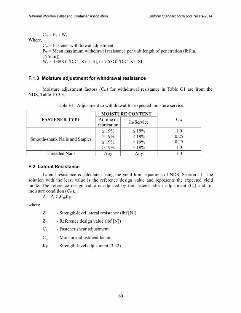
National Wooden Pallet and Container Association Uniform Standard for Wood Pallets-2014
60
Where,
Cw = Pw / Wr
Cw = Fastener withdrawal adjustment Pw = Mean maximum withdrawal resistance per unit length of penetration (lbf/in.
[N/mm]) Wr = 1380G2.5DsCm KF [US], or 9.58G2.5DsCmKF [SI]
F.1.3 Moisture adjustment for withdrawal resistance
Moisture adjustment factors (Cm) for withdrawal resistance in Table C1 are from the
NDS, Table 10.3.3.
Table F1. Adjustment to withdrawal for expected moisture service.
FASTENER TYPE
MOISTURE CONTENT
Cm At time of fabrication
In-Service
Smooth-shank Nails and Staples
≤ 19% ≤ 19% 1.0
> 19%
≤ 19%
≤ 19%
> 19%
0.25 0.25
> 19% > 19% 1.0
Threaded Nails Any Any 1.0
F.2 Lateral Resistance
Lateral resistance is calculated using the yield limit equations of NDS, Section 11. The
solution with the least value is the reference design value and represents the expected yield
mode. The reference design value is adjusted by the fastener shear adjustment (Cz) and for
moisture condition (Cm), Z = Zr CzCmKF
where
Z - Strength-level lateral resistance (lbf [N])
Zr - Reference design value (lbf [N])
Cz - Fastener shear adjustment
Cm - Moisture adjustment factor
KF - Strength-level adjustment (3.32)
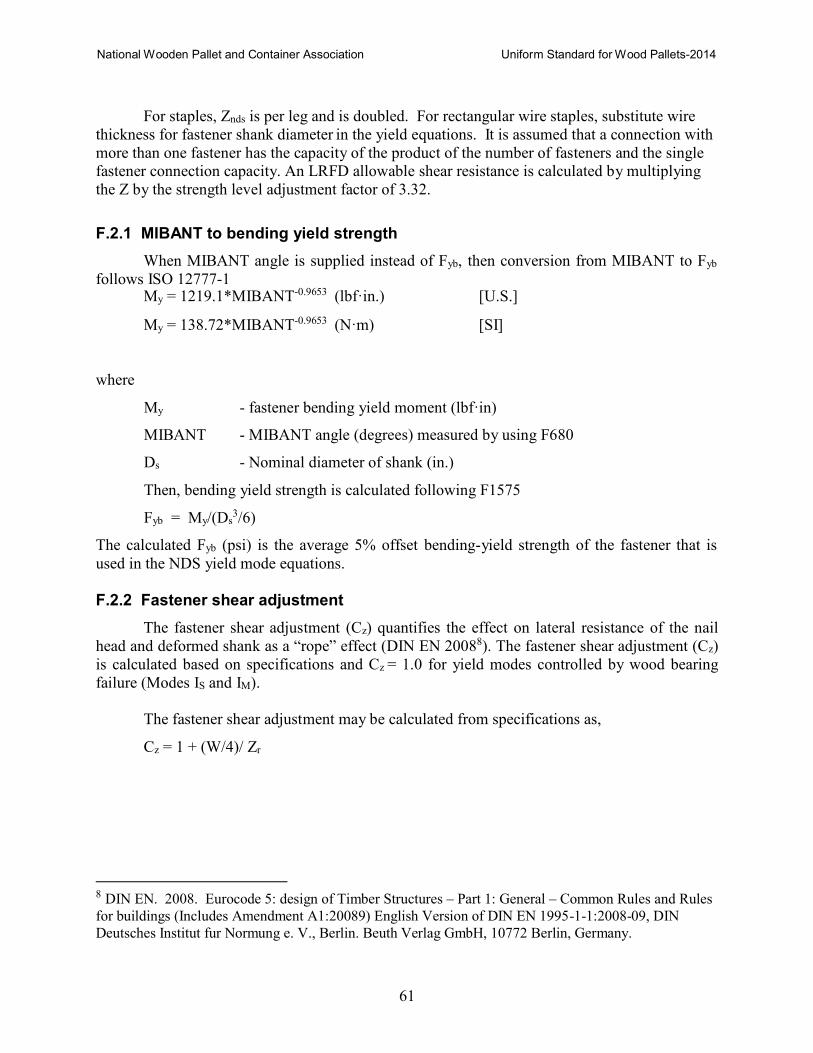
National Wooden Pallet and Container Association Uniform Standard for Wood Pallets-2014
61
For staples, Znds is per leg and is doubled. For rectangular wire staples, substitute wire
thickness for fastener shank diameter in the yield equations. It is assumed that a connection with
more than one fastener has the capacity of the product of the number of fasteners and the single
fastener connection capacity. An LRFD allowable shear resistance is calculated by multiplying
the Z by the strength level adjustment factor of 3.32.
F.2.1 MIBANT to bending yield strength
When MIBANT angle is supplied instead of Fyb, then conversion from MIBANT to Fyb
follows ISO 12777-1 My = 1219.1*MIBANT-0.9653 (lbf·in.) [U.S.]
My = 138.72*MIBANT-0.9653 (N·m) [SI]
where
My - fastener bending yield moment (lbf·in)
MIBANT - MIBANT angle (degrees) measured by using F680
Ds - Nominal diameter of shank (in.)
Then, bending yield strength is calculated following F1575
Fyb = My/(Ds3/6)
The calculated Fyb (psi) is the average 5% offset bending-yield strength of the fastener that is
used in the NDS yield mode equations.
F.2.2 Fastener shear adjustment
The fastener shear adjustment (Cz) quantifies the effect on lateral resistance of the nail
head and deformed shank as a “rope” effect (DIN EN 20088). The fastener shear adjustment (Cz)
is calculated based on specifications and Cz = 1.0 for yield modes controlled by wood bearing
failure (Modes IS and IM).
The fastener shear adjustment may be calculated from specifications as,
Cz = 1 + (W/4)/ Zr
8 DIN EN. 2008. Eurocode 5: design of Timber Structures – Part 1: General – Common Rules and Rules
for buildings (Includes Amendment A1:20089) English Version of DIN EN 1995-1-1:2008-09, DIN
Deutsches Institut fur Normung e. V., Berlin. Beuth Verlag GmbH, 10772 Berlin, Germany.
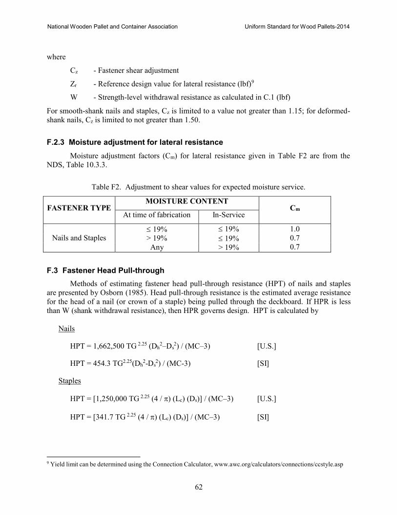
National Wooden Pallet and Container Association Uniform Standard for Wood Pallets-2014
62
s
s
where
Cz - Fastener shear adjustment
Zr - Reference design value for lateral resistance (lbf)9
W - Strength-level withdrawal resistance as calculated in C.1 (lbf)
For smooth-shank nails and staples, Cz is limited to a value not greater than 1.15; for deformed-
shank nails, Cz is limited to not greater than 1.50.
F.2.3 Moisture adjustment for lateral resistance
Moisture adjustment factors (Cm) for lateral resistance given in Table F2 are from the
NDS, Table 10.3.3.
Table F2. Adjustment to shear values for expected moisture service.
FASTENER TYPE MOISTURE CONTENT
Cm
At time of fabrication In-Service
Nails and Staples ≤ 19% ≤ 19% 1.0
> 19% ≤ 19% 0.7
Any > 19% 0.7
F.3 Fastener Head Pull-through
Methods of estimating fastener head pull-through resistance (HPT) of nails and staples
are presented by Osborn (1985). Head pull-through resistance is the estimated average resistance
for the head of a nail (or crown of a staple) being pulled through the deckboard. If HPR is less
than W (shank withdrawal resistance), then HPR governs design. HPT is calculated by
Nails
HPT = 1,662,500 TG 2.25 (Dh2–D 2) / (MC–3) [U.S.]
HPT = 454.3 TG2.25(Dh2-D 2) / (MC-3) [SI]
Staples
HPT = [1,250,000 TG 2.25 (4 / π) (Lc) (Ds)] / (MC–3) [U.S.]
HPT = [341.7 TG 2.25 (4 / π) (Lc) (Ds)] / (MC–3) [SI]
9 Yield limit can be determined using the Connection Calculator, www.awc.org/calculators/connections/ccstyle.asp
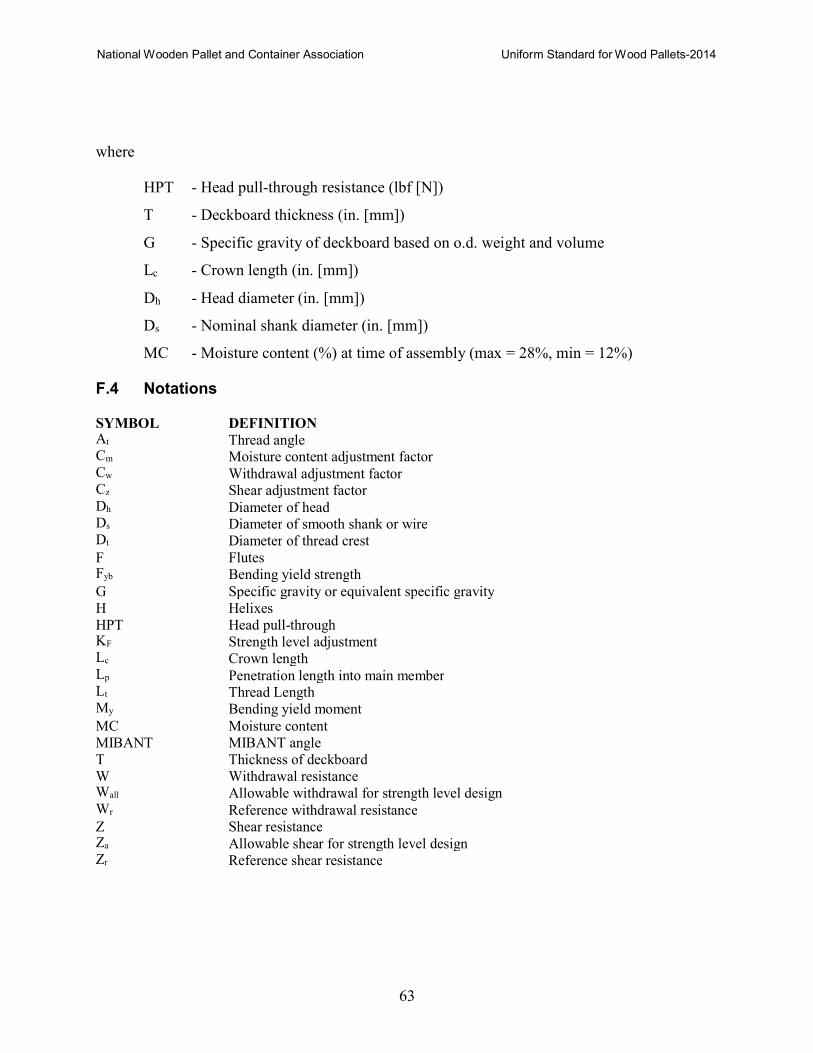
National Wooden Pallet and Container Association Uniform Standard for Wood Pallets-2014
63
where
HPT - Head pull-through resistance (lbf [N])
T - Deckboard thickness (in. [mm])
G - Specific gravity of deckboard based on o.d. weight and volume
Lc - Crown length (in. [mm])
Dh - Head diameter (in. [mm])
Ds - Nominal shank diameter (in. [mm])
MC - Moisture content (%) at time of assembly (max = 28%, min = 12%)
F.4 Notations
SYMBOL DEFINITION At Thread angle Cm Moisture content adjustment factor Cw Withdrawal adjustment factor Cz Shear adjustment factor Dh Diameter of head Ds Diameter of smooth shank or wire Dt Diameter of thread crest
F Flutes Fyb Bending yield strength
G Specific gravity or equivalent specific gravity
H Helixes
HPT Head pull-through KF Strength level adjustment Lc Crown length Lp Penetration length into main member Lt Thread Length My Bending yield moment
MC Moisture content
MIBANT MIBANT angle
T Thickness of deckboard
W Withdrawal resistance Wall Allowable withdrawal for strength level design Wr Reference withdrawal resistance Z Shear resistance Za Allowable shear for strength level design Zr Reference shear resistance
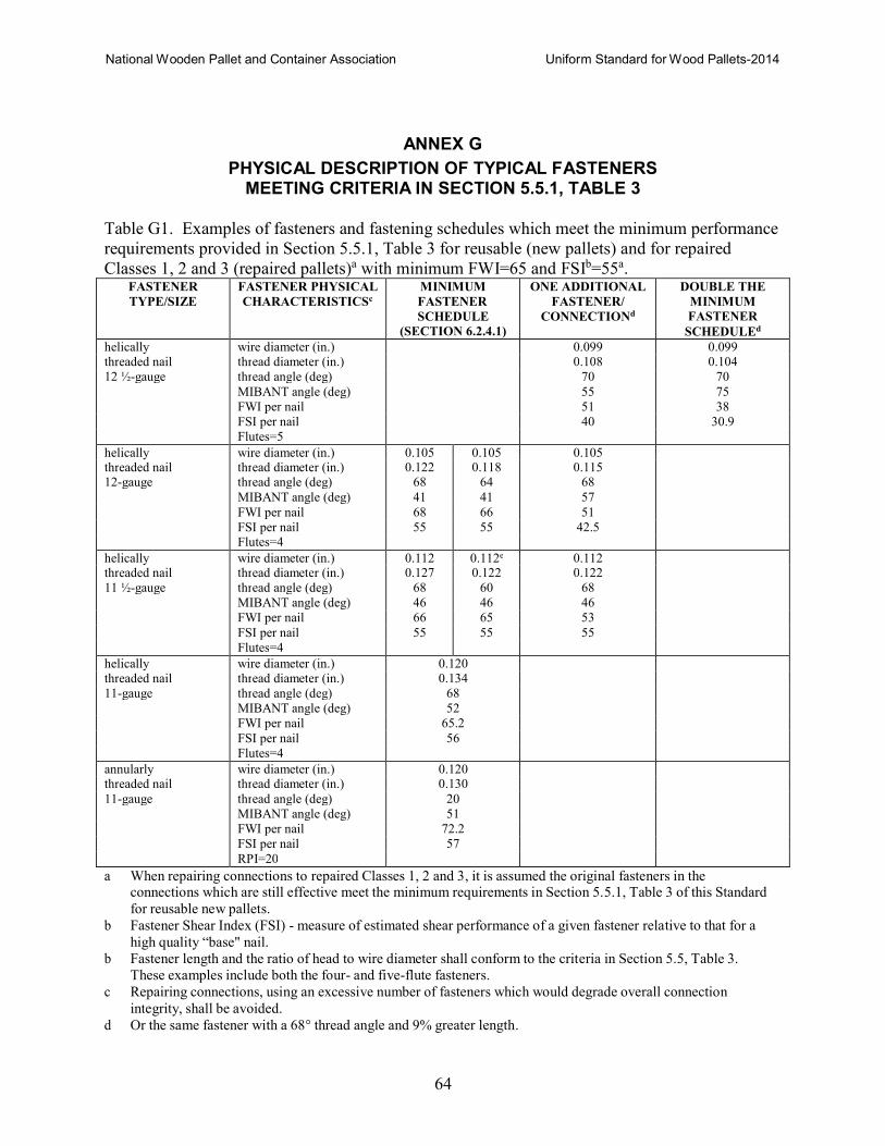
National Wooden Pallet and Container Association Uniform Standard for Wood Pallets-2014
64
ANNEX G
PHYSICAL DESCRIPTION OF TYPICAL FASTENERS MEETING CRITERIA IN SECTION 5.5.1, TABLE 3
Table G1. Examples of fasteners and fastening schedules which meet the minimum performance
requirements provided in Section 5.5.1, Table 3 for reusable (new pallets) and for repaired
Classes 1, 2 and 3 (repaired pallets)a with minimum FWI=65 and FSIb=55a. FASTENER
TYPE/SIZE
FASTENER PHYSICAL
CHARACTERISTICSc
MINIMUM
FASTENER
SCHEDULE (SECTION 6.2.4.1)
ONE ADDITIONAL
FASTENER/
CONNECTIONd
DOUBLE THE
MINIMUM
FASTENER
SCHEDULEd
helically wire diameter (in.) 0.099 0.099 threaded nail thread diameter (in.) 0.108 0.104
12 ½-gauge thread angle (deg) 70 70
MIBANT angle (deg) 55 75
FWI per nail 51 38
FSI per nail 40 30.9
Flutes=5
helically wire diameter (in.) 0.105 0.105 0.105 threaded nail thread diameter (in.) 0.122 0.118 0.115 12-gauge thread angle (deg) 68 64 68
MIBANT angle (deg) 41 41 57
FWI per nail 68 66 51
FSI per nail 55 55 42.5 Flutes=4
helically wire diameter (in.) 0.112 0.112e 0.112
threaded nail thread diameter (in.) 0.127 0.122 0.122
11 ½-gauge thread angle (deg) 68 60 68
MIBANT angle (deg) 46 46 46
FWI per nail 66 65 53
FSI per nail 55 55 55
Flutes=4
helically wire diameter (in.) 0.120 threaded nail thread diameter (in.) 0.134
11-gauge thread angle (deg) 68
MIBANT angle (deg) 52
FWI per nail 65.2
FSI per nail 56
Flutes=4
annularly wire diameter (in.) 0.120 threaded nail thread diameter (in.) 0.130
11-gauge thread angle (deg) 20
MIBANT angle (deg) 51
FWI per nail 72.2
FSI per nail 57
RPI=20
a When repairing connections to repaired Classes 1, 2 and 3, it is assumed the original fasteners in the connections which are still effective meet the minimum requirements in Section 5.5.1, Table 3 of this Standard
for reusable new pallets.
b Fastener Shear Index (FSI) - measure of estimated shear performance of a given fastener relative to that for a
high quality “base" nail.
b Fastener length and the ratio of head to wire diameter shall conform to the criteria in Section 5.5, Table 3.
These examples include both the four- and five-flute fasteners.
c Repairing connections, using an excessive number of fasteners which would degrade overall connection
integrity, shall be avoided.
d Or the same fastener with a 68° thread angle and 9% greater length.
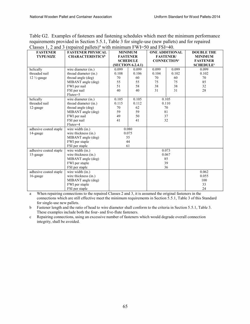
National Wooden Pallet and Container Association Uniform Standard for Wood Pallets-2014
65
Table G2. Examples of fasteners and fastening schedules which meet the minimum performance
requirements provided in Section 5.5.1, Table 3 for single-use (new pallets) and for repaired
Classes 1, 2 and 3 (repaired pallets)a with minimum FWI=50 and FSI=40. FASTENER
TYPE/SIZE
FASTENER PHYSICAL
CHARACTERISTICSb
MINIMUM
FASTENER
SCHEDULE (SECTION 6.2.4.1)
ONE ADDITIONAL
FASTENER/
CONNECTIONc
DOUBLE THE
MINIMUM
FASTENER
SCHEDULEc
helically wire diameter (in.) 0.099 0.099 0.099 0.099 0.099 threaded nail thread diameter (in.) 0.108 0.106 0.104 0.102 0.102
12 ½-gauge thread angle (deg) 70 60 70 60 70
MIBANT angle (deg) 55 55 75 75 85
FWI per nail 51 58 38 38 32
FSI per nail 40 40 31 31 28
Flutes=5
helically wire diameter (in.) 0.105 0.105 0.105 threaded nail thread diameter (in.) 0.115 0.112 0.110
12-gauge thread angle (deg) 70 62 70
MIBANT angle (deg) 59 59 81
FWI per nail 49 50 37
FSI per nail 41 41 32 Flutes=4
adhesive coated staple wire width (in.) 0.080 14-gauge wire thickness (in.) 0.075
MIBANT angle (deg) 55
FWI per staple 44
FSI per staple 61
adhesive coated staple wire width (in.) 0.073 15-gauge wire thickness (in.) 0.067
MIBANT angle (deg) 85
FWI per staple 39
FSI per staple 36
adhesive coated staple wire width (in.) 0.062 16-gauge wire thickness (in.) 0.055
MIBANT angle (deg) 100
FWI per staple 33
FSI per staple 24
a When repairing connections to the repaired Classes 2 and 3, it is assumed the original fasteners in the connections which are still effective meet the minimum requirements in Section 5.5.1, Table 3 of this Standard
for single-use new pallets.
b Fastener length and the ratio of head to wire diameter shall conform to the criteria in Section 5.5.1, Table 3.
These examples include both the four- and five-flute fasteners.
c Repairing connections, using an excessive number of fasteners which would degrade overall connection
integrity, shall be avoided.
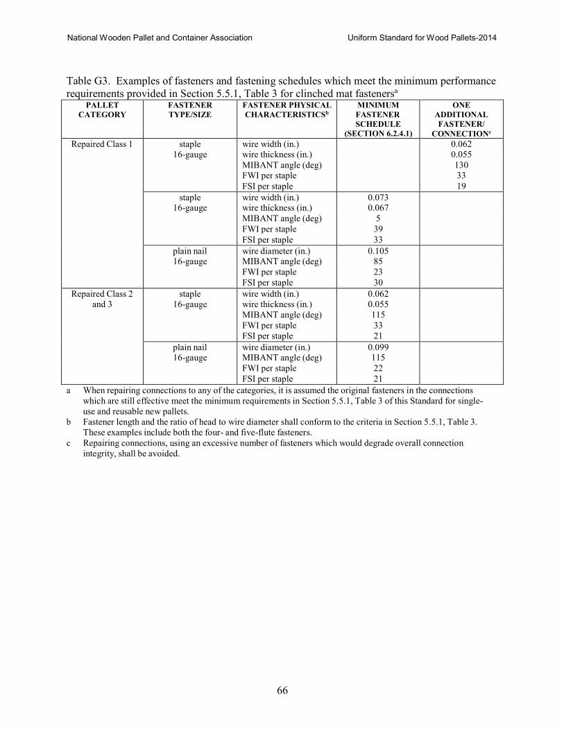
National Wooden Pallet and Container Association Uniform Standard for Wood Pallets-2014
66
Table G3. Examples of fasteners and fastening schedules which meet the minimum performance
requirements provided in Section 5.5.1, Table 3 for clinched mat fastenersa
PALLET
CATEGORY
FASTENER
TYPE/SIZE
FASTENER PHYSICAL
CHARACTERISTICSb
MINIMUM
FASTENER
SCHEDULE (SECTION 6.2.4.1)
ONE
ADDITIONAL
FASTENER/
CONNECTIONc
Repaired Class 1 staple wire width (in.) 0.062 16-gauge wire thickness (in.) 0.055
MIBANT angle (deg) 130 FWI per staple 33
FSI per staple 19
staple wire width (in.) 0.073
16-gauge wire thickness (in.) 0.067
MIBANT angle (deg) 5
FWI per staple 39
FSI per staple 33
plain nail wire diameter (in.) 0.105
16-gauge MIBANT angle (deg) 85
FWI per staple 23
FSI per staple 30
Repaired Class 2 staple wire width (in.) 0.062
and 3 16-gauge wire thickness (in.) 0.055
MIBANT angle (deg) 115
FWI per staple 33
FSI per staple 21
plain nail wire diameter (in.) 0.099
16-gauge MIBANT angle (deg) 115
FWI per staple 22
FSI per staple 21
a When repairing connections to any of the categories, it is assumed the original fasteners in the connections
which are still effective meet the minimum requirements in Section 5.5.1, Table 3 of this Standard for single-
use and reusable new pallets.
b Fastener length and the ratio of head to wire diameter shall conform to the criteria in Section 5.5.1, Table 3.
These examples include both the four- and five-flute fasteners.
c Repairing connections, using an excessive number of fasteners which would degrade overall connection
integrity, shall be avoided.