Uniform Design and construction Standards - Section 4 ... Distribution PDFs/Uniform... · Uniform...
79
UNIFORM DESIGN AND CONSTRUCTION STANDARDS FOR EXTENDING WATER DISTRIBUTION SYSTEMS SECTION 4 MATERIALS AND PERFORMANCE SPECIFICATIONS Revised: March 5, 2018
Transcript of Uniform Design and construction Standards - Section 4 ... Distribution PDFs/Uniform... · Uniform...
UNIFORMDESIGNANDCONSTRUCTIONSTANDARDSFOREXTENDINGWATER
DISTRIBUTIONSYSTEMS
SECTION4
MATERIALSANDPERFORMANCESPECIFICATIONS
Revised: March 5, 2018

SITE WORK
TABLE OF CONTENTS
SECTION TITLE
02225 Trenching
02227 Backfilling
02229 Rock Removal
02230 Select Fill
02600 Pipe Installation
02610 Ductile Iron Pipe
02630 Service Connections
02650 Water Main Connections
02655 Water System Appurtenances
02660 Water Valves
02670 Bores
02671 Horizontal Directional Drilling
02675 Pressure Testing, Flushing, Disinfecting and Health Sampling of Water Mains
02680 Water System Abandonments
02700 Concrete Thrust Blocks

Uniform Design and Construction Standards Materials & Performance For extending Water Distribution Systems Specifications 02225
STND 6/16
5‐2‐5
SECTION 02225
TRENCHING
PART 1 General
1.01 Section Includes A. Trenches for pipelines and appurtenances
B. Mainlining trenches. C. Encountering underground facilities. D. Existing structures and pavements within the trench limits. E. Trees, bushes and plantings. F. Surplus materials. G. Dust control. H. Voids under adjacent structures.
1.02 Related Sections A. Section 02227 – Backfilling B. Section 02229 – Rock Removal C. Section 02230 – Select Fill D. Section 02670 – Bores E. Section 02671 – Horizontal Directional Drilling
1.03 Definitions A. Trenching or Excavation
1. Grubbing, stripping, removing, storing and re‐handling of all materials of every name and nature necessary to be removed for all purposes incidental to the construction and completion of all the Work under construction;
2. All dikes, ditches, flumes, cofferdams, pumping, bailing, draining, well points, or
otherwise disposing of water;
Uniform Design and Construction Standards Materials & Performance For extending Water Distribution Systems Specifications 02225
STND 6/16
5‐2‐6
3. The removing and disposing of all surplus materials from the excavations in the manner
specified;
4. The maintenance, accommodation and protection of travel;
5. The supporting and protecting of all tracks, rails, buildings, curbs, sidewalks, pavements, overhead wires, poles, trees, vines, shrubbery, pipes, sewers, conduits or other structures or property in the vicinity of the Work, whether over or underground or which appear within or adjacent to the excavations and the restoration of the same in case of settlement or other injury;
6. All temporary bridging and fencing and the removing of same.
B. Earth
1. All materials such as sand, gravel, clay, loam, ashes, cinders, pavement, muck, roots, pieces of timber, soft or disintegrated rock, not requiring blasting, barring, or wedging from their original beds, and specifically excluding all ledge or bedrock and individual boulders or masonry larger than one‐half cubic yard in volume.
C. Backfilling
1. The refilling of excavation and trenches to the line of filling indicated on the Approved Plans or as directed using materials suitable for refilling of excavations and trenches; and the compacting of all materials used in filling or refilling by rolling, ramming, watering, puddling, etc., as may be required.
D. Native Materials
1. Excavated materials such as sand, gravel, and clay, suitable for backfilling and capable of being satisfactorily compacted within the trench. Rock with no dimension greater than 6 inches may also be included.
E. Select Native Materials
1. Excavated materials, such as sand, gravel, and clay, suitable for backfilling and capable of being satisfactorily compacted within the trench. Rock with no dimension greater than 2 inches may also be included.
F. Spoils
1. Surplus excavated materials not required or not suitable for backfill or embankments.
Uniform Design and Construction Standards Materials & Performance For extending Water Distribution Systems Specifications 02225
STND 6/16
5‐2‐7
G. Embankments
1. Fills constructed above the original surface of the ground or such other elevation as specified or directed.
H. Limiting Subgrade
1. The underside of the pipe barrel for pipelines.
I. Excavation Below Subgrade
1. Excavation below the limiting subgrade of pipelines. 2. Excavate to such new lines and grades as required when material encountered at the
limiting subgrade is not suitable for proper support of pipelines.
PART 2 Products
2.01 Fill Materials A. Type 1 Select Fill
B. Type 2 Select Fill
C. Type 5 Select Fill
PART 3 Execution
3.01 Preparation A. Identify required lines, levels, contours, and datum. Locate all utilities and underground
obstructions prior to starting excavations, including cutting pavement.
B. Maintain support of existing power, lighting, telephone, traffic control and utility poles adjacent to excavations as required by the owners of the poles.
3.02 Excavation
A. Excavate trenches to the lines and grades specified and as required. Backfill with special
granular materials, concrete or other materials as directed by the Engineer, any excavated space carried beyond or below the lines and grades shown on the Approved Plans, or as directed by the Engineer. Backfill unauthorized excavations at the Contractor’s expense.

Uniform Design and Construction Standards Materials & Performance For extending Water Distribution Systems Specifications 02225
STND 6/16
5‐2‐8
B. Excavate the trench sides vertically between the centerline of the pipe and an elevation 1 foot above the top of the pipe unless this conflicts with the requirements of OSHA. In the case of rock excavation, excavate to 6 inches below invert elevation of pipe and 12 inches wider than the nominal pipe diameter. Maintain a minimum clearance of 6 inches around the pipe.
C. Provide and maintain proper and satisfactory means and devices for the removal of all
water entering the excavations, and remove all such water as fast as it may collect in such a manner as shall not interfere with the progression of the Work or the proper placing of pipes or other work.
D. Prevent damage to surrounding pavement, gutters, and structures while excavating. E. Furnish, place and maintain such sheeting, bracing and shoring as may be required to
support the sides and ends of excavations in such manner as to prevent any movement which could, in any way, damage the pipe, structures, or other work; diminish the width necessary for construction; otherwise damage or delay the work; endanger existing structures, pipes or pavements.
In no case will bracing be permitted against pipes or structures in trenches or other excavations. The adequacy of all sheeting and bracing is the sole responsibility of the Contractor.
F. Discontinue machine excavation in the vicinity of pipes, conduits and other underground
structures and facilities and complete the excavation with hand tools as required by Industrial Code Rule 753.
G. When determination of the exact location of Authority pipes or other underground structure is necessary for completing the work properly, excavate test holes to determine such locations.
H. When the bottom of any excavation is taken out beyond the limits indicated or prescribed,
backfill and compact the resulting void with Type 1 or 2 Select Fill, compacted to 95% maximum modified Proctor density.
I. Remove materials which, in the opinion of the Engineer, are found to be unsuitable for
foundation of the pipeline and appurtenances during excavation. J. Use suitable surplus excavated materials for backfill of excavations in rock or to replace
other materials unacceptable for use as backfill except in areas which require select backfill.
~ END OF SECTION ~
Uniform Design and Construction Standards Materials & Performance For Extending Water Distribution Systems Specifications 02227
STND 6/16
5‐2‐9
SECTION 02227
BACKFILLING
PART 1 General
1.01 Section Includes A. Backfilling around and above pipe and appurtenances.
B. Consolidation and compaction.
1.02 Related Sections A. Section 02225 – Trenching B. Section 02230 – Select Fill C. Section 02600 – Pipe Installation
1.03 References A. ANSI/ASTM D1556 – Test Method for Density of Soil in Place by the Sand‐Cone Method.
B. ASTM D2167 – Test Method for Density and Unit Weight or Soil in Place by the Rubber
Balloon Method. C. ASTM D2922 – Test Methods for Density of Soil and Soil‐Aggregate in Place by Nuclear
Methods (Shallow Depth). D. ASTM D3017 – Test Method for Water Content of Soil and Rock in Place by Nuclear
Methods.
PART 2 Products – Not Used
PART 3 Execution
3.01 Examination
A. Verify installation has been inspected by the Engineer.
Uniform Design and Construction Standards Materials & Performance For Extending Water Distribution Systems Specifications 02227
STND 6/16
5‐2‐10
3.02 Preparation A. Cut out soft areas of subgrade not capable of in situ compaction. Backfill with select fill and
compact to 95% maximum modified Proctor density.
B. When required to obtain the optimum moisture content, add, at no additional cost the Authority, sufficient water during compaction to assure the specified maximum density of the backfill. If, due to rain or other causes, the materials exceed the optimum moisture content, it shall be allowed to dry, assisted if necessary, before resuming compaction or filling efforts.
3.03 Bedding and Backfilling Pipe Zone A. Bed pipe with 6 inches of Select Native Material. When trench bottom is in rock, bed with 6
inches of Select Native Material or Type 4 Select Fill.
B. Backfill the remaining pipe zone with Select Native Material in non‐pavement areas or Type 2 Select Fill in pavement areas.
C. Place materials in by shovel in such a manner as not to damage pipe or appurtenances and
in layers not to exceed 6 inches in depth. Compact to 85% maximum standard Proctor density in non‐pavement areas, and compact to 95% maximum modified Proctor density in pavement areas.
3.04 Backfilling Above Pipe Zone
A. Backfill all excavations to the original surface of the ground or to such other grades as may
be shown, specified or directed.
B. Backfill non‐pavement areas with Native Material, which can be satisfactorily compacted during refilling of the excavation, or as directed by the Engineer.
3.05 Field Quality Control
A. The Contractor shall be responsible for all damage or injury done to pipes, structures,
property or persons due to improper placing or compacting of backfill.
~ END OF SECTION ~
Uniform Design and Construction Standards Materials & Performance For Extending Water Distribution Systems Specifications 02229
STND 6/16
5‐2‐11
SECTION 02229
ROCK REMOVAL PART 1 General 1.01 Section Includes
A. Removal of rock by mechanical methods.
1.02 Related Sections
A. Section 02225 – Trenching B. Section 02227 – Backfilling
1.03 Definitions A. Rock: Solid mineral material with a volume in excess of 1/2 cubic yard or solid mineral
material that cannot be removed with a 3/4 cubic yard capacity power shovel and which requires drilling, wedging, barring or hammering.
1.04 Submittals A. Shop Drawings: Indicate proposed method of rock removal.
PART 2 Products
2.01 Materials
A. Expansive Disintegration Compounds: Grout‐type mix of materials that expand upon curing.
Select correct product type for the specific temperature range. 1. Manufacturers:
a. ECOBUST
b. Crackamite
PART 3 Execution 3.01 Preparation
A. Identify required lines, levels, contours and datum.
Uniform Design and Construction Standards Materials & Performance For Extending Water Distribution Systems Specifications 02229
STND 6/16
5‐2‐12
3.02 Rock Removal – Mechanical Method A. Excavate and remove rock by the mechanical method. Hammer or drill holes and utilize
tools, wedges or expansive disintegration compounds to fracture rock.
3.03 Excavation, Backfill, and Disposal A. Remove rock from the excavation to the required lines and grades.
B. Excavate to 6 inches below invert elevation of pipe, conduit or structure, and 12 inches
wider than the nominal pipe or conduit diameter or structure width. Maintain a minimum clearance of 6 inches around pipe.
C. Correct over‐excavation of rock in accordance with requirements of Specification 02225. D. Install bedding and backfill in accordance with Specification 02227.
~ END OF SECTION ~
Uniform Design and Construction Standards Materials & Performance For Extending Water Distribution Systems Specifications 02230
STND 10/16
5‐2‐13
SECTION 02230
SELECT FILL PART 1 General
1.01 Section Includes
A. Types of select fill.
B. Placement and installation. C. Disposal of displaced material.
1.02 Related Sections A. Section 02227 – Backfilling
1.03 References A. ASTM D422, Standard Method for Particle‐Size Analysis of Soils.
1.04 Submittals
A. Submit name of supplier and source for each type of select fill material.
B. Provide sample and test report for each type of select fill material.
PART 2 Products
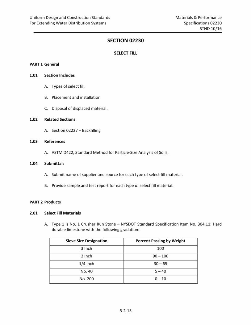
2.01 Select Fill Materials A. Type 1 is No. 1 Crusher Run Stone – NYSDOT Standard Specification Item No. 304.11: Hard
durable limestone with the following gradation:
Sieve Size Designation Percent Passing by Weight
3 Inch 100
2 Inch 90 – 100
1/4 Inch 30 – 65
No. 40 5 – 40
No. 200 0 – 10
Uniform Design and Construction Standards Materials & Performance For Extending Water Distribution Systems Specifications 02230
STND 10/16
5‐2‐14
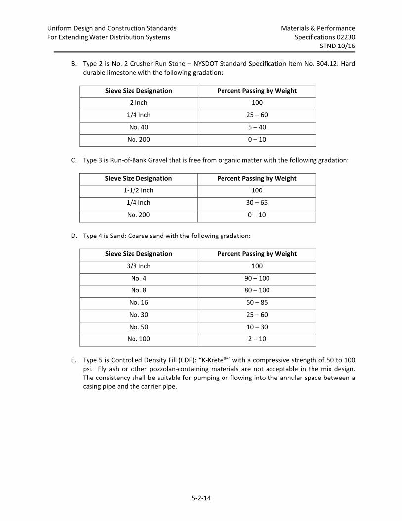
B. Type 2 is No. 2 Crusher Run Stone – NYSDOT Standard Specification Item No. 304.12: Hard durable limestone with the following gradation:
Sieve Size Designation Percent Passing by Weight
2 Inch 100
1/4 Inch 25 – 60
No. 40 5 – 40
No. 200 0 – 10
C. Type 3 is Run‐of‐Bank Gravel that is free from organic matter with the following gradation:
Sieve Size Designation Percent Passing by Weight
1‐1/2 Inch 100
1/4 Inch 30 – 65
No. 200 0 – 10
D. Type 4 is Sand: Coarse sand with the following gradation:
Sieve Size Designation Percent Passing by Weight
3/8 Inch 100
No. 4 90 – 100
No. 8 80 – 100
No. 16 50 – 85
No. 30 25 – 60
No. 50 10 – 30
No. 100 2 – 10
E. Type 5 is Controlled Density Fill (CDF): “K‐Krete®” with a compressive strength of 50 to 100
psi. Fly ash or other pozzolan‐containing materials are not acceptable in the mix design. The consistency shall be suitable for pumping or flowing into the annular space between a casing pipe and the carrier pipe.
Uniform Design and Construction Standards Materials & Performance For Extending Water Distribution Systems Specifications 02230
STND 10/16
5‐2‐15
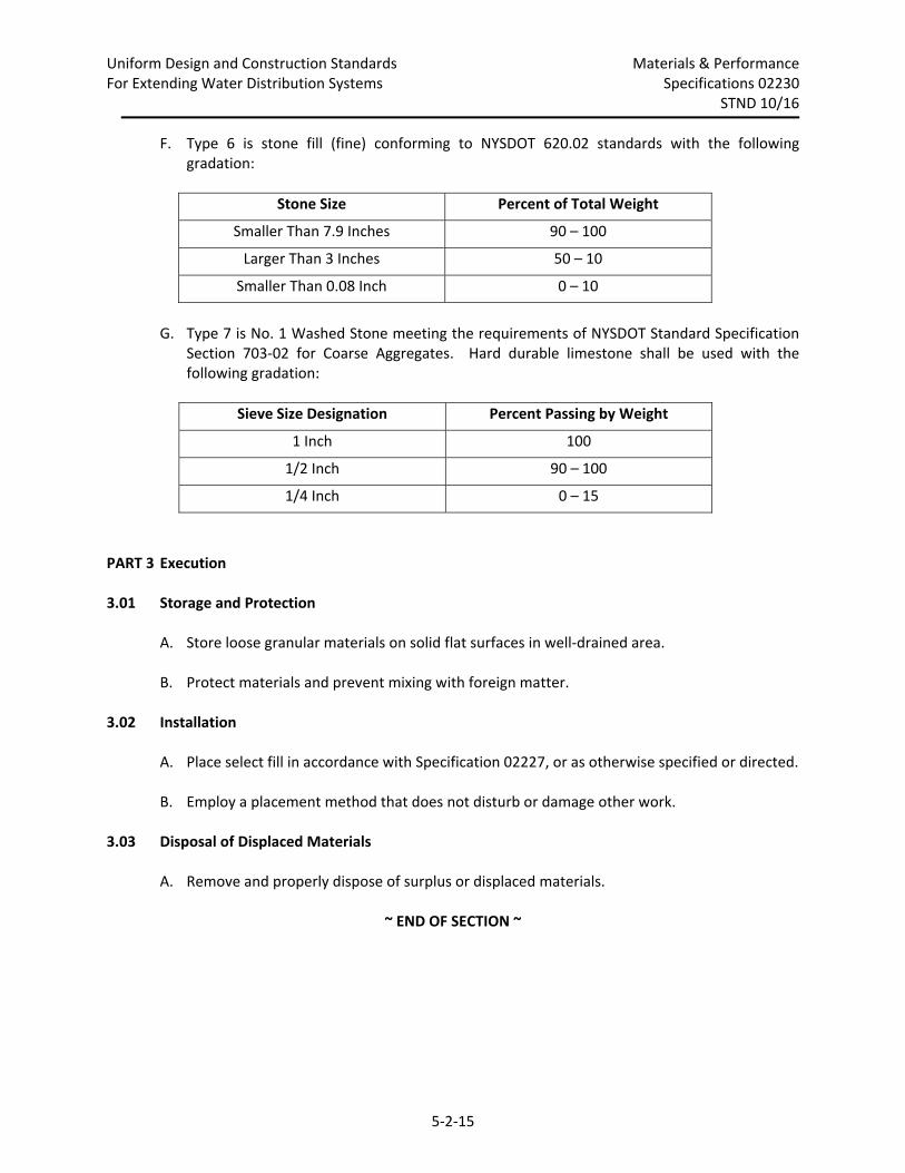
F. Type 6 is stone fill (fine) conforming to NYSDOT 620.02 standards with the following gradation:
Stone Size Percent of Total Weight
Smaller Than 7.9 Inches 90 – 100
Larger Than 3 Inches 50 – 10
Smaller Than 0.08 Inch 0 – 10
G. Type 7 is No. 1 Washed Stone meeting the requirements of NYSDOT Standard Specification
Section 703‐02 for Coarse Aggregates. Hard durable limestone shall be used with the following gradation:
Sieve Size Designation Percent Passing by Weight
1 Inch 100
1/2 Inch 90 – 100
1/4 Inch 0 – 15
PART 3 Execution
3.01 Storage and Protection
A. Store loose granular materials on solid flat surfaces in well‐drained area.
B. Protect materials and prevent mixing with foreign matter.
3.02 Installation A. Place select fill in accordance with Specification 02227, or as otherwise specified or directed.
B. Employ a placement method that does not disturb or damage other work.
3.03 Disposal of Displaced Materials A. Remove and properly dispose of surplus or displaced materials.
~ END OF SECTION ~

5‐2‐16
~THIS PAGE INTENTIONALLY LEFT BLANK~
Uniform Design and Construction Standards Materials & Performance For Extending Water Distribution Systems Specifications 02600
STND 10/16
5‐2‐17
SECTION 02600
PIPE INSTALLATION
PART 1 General
1.01 Section Includes A. Installation of pipe, fittings and appurtenances by open cut for water distribution and
transmission lines.
B. Installation of pipe by horizontal directional drilling (general requirements).
1.02 Related Sections A. Section 02225 – Trenching B. Section 02227 – Backfilling C. Section 02230 – Select Fill D. Section 02610 – Ductile Iron Pipe E. Section 02630 – Service Connections F. Section 02650 – Water Main Connections G. Section 02655 – Water System Appurtenances H. Section 02660 – Water Valves I. Section 02670 – Bores J. Section 02671 – Horizontal Directional Drilling K. Section 02675 – Pressure Testing, Flushing, Disinfecting, and Health Sampling of Water
Mains L. Section 02700 – Concrete Thrust Blocks
1.03 References A. ANSI/AWWA C600 – Installation of Ductile Iron Mains and their Appurtenances.
Uniform Design and Construction Standards Materials & Performance For Extending Water Distribution Systems Specifications 02600
STND 10/16
5‐2‐18
1.04 Delivery, Storage and Handling A. Deliver, store, protect and handle products under provisions of the General Conditions.
PART 2 Products
2.01 Pipe A. Pipe
1. Materials for piping, joints and fittings shall be specified in the section for the type of
pipe to be installed as shown on Approved Plans.
2. All pipe and appurtenances to comply with the applicable standards for their type of material.
B. Joints
1. Type of joints as specified in Bid Items or as shown on Approved Plans.
C. Inspection
1. Inspect pipe and appurtenances upon delivery and prior to installation for conformance
with standards and Specifications.
2.02 Bedding Materials A. Bedding: Fill type as specified in Specification 02227.
2.03 Accessories
A. Concrete for thrust blocks: Concrete type specified in Specification 02700.
PART 3 Execution
3.01 Preparation A. Place pipe and related appurtenances on supports above flood level within right‐of‐way or
easements or other approved locations. Use slings or other approved methods to unload and place pipe. Do not dump pipe from trucks. Cover both ends of each pipe segment when in outdoor storage or staging areas.
B. Field cut pipes in accordance with manufacturer’s instructions. Bevel all cuts. Remove all burrs.
Uniform Design and Construction Standards Materials & Performance For Extending Water Distribution Systems Specifications 02600
STND 10/16
5‐2‐19
C. Remove scale and dirt on inside and outside of pipe before assembly. D. When material unsuitable for foundation has been removed, as outlined in Specification
02225, replace with select fill compacted to 95% Maximum Standard Proctor Density. Payment shall be made under the appropriate item of the Bid.
E. Excavate bell holes at each joint to permit the joint to be made properly and provide
uniform and continuous bearing for the pipe.
3.02 Installation – General A. Maintain a minimum vertical separation of 18 inches when water main crosses above storm
or sanitary sewers. In Monroe County, maintain a minimum vertical separation of 6 inches when water main crosses above storm or sanitary sewers.
B. Maintain a minimum vertical separation of 18 inches with one full length of water main centered around crossing when water main crosses under storm or sanitary sewers.
C. Maintain a minimum horizontal separation of 10 feet edge to edge when the water main is installed parallel to a storm or sanitary sewer. In Monroe County, maintain a minimum horizontal separation of 3 feet when the water main is installed 6 inches above and parallel to a storm or sanitary sewer and, maintain a minimum vertical separation of 18 inches when the water main is installed below and parallel to a storm or sanitary sewer with less than 10 feet of horizontal separation.
D. Examine all pipe and appurtenances prior to installation for defects and damage.
Immediately remove from site all pipe or appurtenances which are known to be defective or damaged.
E. Maintain water‐tight temporary plugs in all open ends of pipe when laying pipe is not
actively in progress. F. Maintain trench free of standing water when laying pipe. Prevent foreign material from
entering pipe during installation. When such material enters pipe, Owner may require additional flushing procedures. When pipe is flooded during construction, drain water and flush with potable water. Chlorinate flooded section of pipe with water having a minimum free chlorine residual of 25 parts per million (PPM) after 24 hours of contact time.
G. In all areas where the surface elevation of the proposed trench is above that of the adjacent
road or highway, install the water main to a depth that will result in a 5 foot minimum elevation difference between the top of the proposed pipe line and center line of adjacent road or highway.
Uniform Design and Construction Standards Materials & Performance For Extending Water Distribution Systems Specifications 02600
STND 10/16
5‐2‐20
Install pipe with a minimum cover, as measured from final grade, of 5 feet over the top of the pipe. Install pipe that runs longitudinally under street and highway pavement and adjacent shoulders with a minimum cover of 6 feet over the top of the pipe.
H. Prevent floatation of the pipe in the event of water entering trench. I. Route pipe as shown on Approved Plans and as required by actual location of utilities and
structures. Verify utility depths in advance of crossings and deflect pipe accordingly to maintain required cover and vertical clearances as required by each utility.
J. Install pipe in accordance with the manufacturer’s instructions. K. Orient vertical bends with one leg horizontal L. Install temporary facilities as required by Approved Plans or as necessary to permit flushing,
pressure testing, chlorine injection for disinfecting, dechlorinating and sampling. Backfill and restore all excavations made to install these fittings in accordance with Section 02227.
M. Install additional fittings as directed by Engineer. N. Install temporary air releases as specified or shown on Approved Plans. O. Install temporary health sampling points as indicated on Approved Plans and as specified in
Section 02675, Article 3.03G. P. Install thrust blocks at all tees, bends and reducers. Q. Swab disinfect all pipe, fitting and appurtenances installed for tie‐in connections as specified
in Section 02675, Article 3.03I.
~ END OF SECTION~
Uniform Design and Construction Standards Materials & Performance For extending Water Distribution Systems Specifications 02610
STND 6/16
5‐2‐21
SECTION 02610
DUCTILE IRON PIPE
PART 1 General
1.01 Section Includes A. Ductile iron pipe and fittings for water distribution and transmission lines.
1.02 Related Sections
A. Section 02600 – Pipe Installation
B. Section 02650 – Water Main Connections C. Section 02655 – Water System Appurtenances D. Section 02670 – Bores E. Section 02671 – Horizontal Directional Drilling F. Section 02675 – Pressure Testing, Flushing, Disinfecting & Health Sampling of Water Mains
1.03 References A. ANSI/AWWA C104 – Cement Mortar Lining for Ductile Iron Pipe and Fittings for Water.
B. ANSI/AWWA C105 – Polyethylene Encasement for Ductile Iron Pipe Systems. C. ANSI/AWWA C110 – Ductile Iron and Gray Iron Fittings, 3 Inch through 48 Inch, for Water
and Other Liquids. D. ANSI/AWWA C111 – Rubber Gasket Joints for Ductile Iron and Gray Iron Pressure Pipe and
Fittings. E. ANSI/AWWA C116 – Protective Fusion‐Bonded Epoxy Coatings for the Interior and Exterior
Surfaces of Ductile‐Iron and Gray‐Iron Fittings. F. ANSI/AWWA C151 – Ductile Iron Pipe, Centrifugally Cast in Metal Molds or Sand Lined
Molds, for Water or Other Liquids. G. ANSI/AWWA C153 – Ductile Iron Compact Fittings for Water Service. H. ANSI/AWWA C550 – Protective Interior Coatings for Valves and Hydrants.
Uniform Design and Construction Standards Materials & Performance For extending Water Distribution Systems Specifications 02610
STND 6/16
5‐2‐22
1.04 Submittals A. Product Data: Provide data on pipe materials, pipe fittings, accessories and polyethylene
encasement.
B. Manufacturer’s Certificate: Certify that products meet or exceed specified requirements.
PART 2 Products
2.01 General Material Requirements
A. All pipe and fittings shall be NSF‐61 Certified for contact with drinking water.
2.02 Ductile Iron Pipe
A. Pipe Specifications
1. Pipe: ANSI/AWWA C151.
2. Joints: ANSI/AWWA C111, rubber gasket.
3. Cement Lined: ANSI/AWWA C104.
4. Wall Thickness: Special Thickness Class 52 minimum, unless otherwise scheduled in Bid
Items or shown on Approved Plans. B. Fittings Specifications
1. Fittings: ANSI/AWWA C110 (full body) or ANSI/AWWA C153 (compact)
2. Joints: ANSI/AWWA C111, rubber gasket, mechanical joint, unless otherwise specified.
3. Cement Lined: ANSI/AWWA C104.
4. Fittings/Lining: NSF Approved.
5. Manufacturers:
a. McWane Group (Tyler, Union and Clow).
b. U.S. Pipe.
Uniform Design and Construction Standards Materials & Performance For extending Water Distribution Systems Specifications 02610
STND 6/16
5‐2‐23
2.03 Push‐On Joint Pipe A. Manufacturers:
1. American Pipe: Fastite Joint.
2. U.S. Pipe: Tyton Joint.
3. McWane Group: Fastite or Tyton Joint.
4. Griffin/ U.S. Pipe: Tyton Joint.
2.04 Restrained Joint Pipe
A. Manufacturers:
1. American Pipe: Flex‐Ring.
2. U.S. Pipe: TR FLEX.
3. McWane Group: TR FLEX.
4. Griffin/ U.S. Pipe: TR FLEX.
B. Fittings shall be restrained joint.
2.05 Anchor Pipe
A. Cast Ring Anchor Pipe
1. Sizes 4” x 13”; 6” x 13”, 18”, 24”, and 36”; 8” x 13”and 12” x 13”.
2. Minimum Wall Thickness:
a. 4” – 0.52”
b. 6” – 0.37”
c. 8” – 0.39”
d. 12” – 0.75”
3. Cement Lined: ANSI/AWWA C104
Uniform Design and Construction Standards Materials & Performance For extending Water Distribution Systems Specifications 02610
STND 6/16
5‐2‐24
4. Joints: ANSI/AWWA C111, rubber gasket, mechanical joint, solid gland cast integrally with pipe by swivel gland.
a. Glands: Ductile Iron
5. Ring: Solid anchor ring cast integrally with pipe.
6. Manufacturers:
a. McWane Group (Tyler, Union and Clow): swivel x solid adapter and swivel x swivel
adapter.
B. Welded Ring Anchor Pipe 1. Sizes: 6” x lengths over 36”, 8” x lengths over 13”.
2. Wall Thickness: Special Thickness Class 54 minimum.
3. Cement Lined: ANSI/AWWA C104.
4. Joints: ANSI/AWWA C111, rubber gasket mechanical joint, solid gland by swivel gland or
swivel gland by swivel gland.
a. Glands: Ductile Iron
5. Ring: 1/2” x 1/2" solid anchor ring welded onto pipe on joint side of ring. a. Material: Ductile Iron, ASTM A‐536.
b. Weld:
1. Fusion weld, continuous short arc. 2. AWS 5.15 ENiFeMN‐CI Electrode (NI ROD 44).
6. Manufacturers:
a. Higgins Engineering, Inc. (must specifically request Special Thickness Class 54 pipe).
2.06 Mechanical Joint Adaptors A. Mechanical joint to mechanical joint.
B. Material/Working Pressure: ANSI/AWWA C153 and C110.
C. Lining/Coating: ANSI/AWWA C116 and C550 (fusion‐bonded epoxy).
Uniform Design and Construction Standards Materials & Performance For extending Water Distribution Systems Specifications 02610
STND 6/16
5‐2‐25
D. Gaskets/Bolts: ANSI/AWWA C111. E. Sizes: 4” – 36” F. Manufacturer
1. Infact Corporation: Foster Adaptor®.
2.07 Push‐On Joint Restraint A. Specifications:
1. Rubber gasket per ANSI/AWWA C111.
2. Stainless steel locking segments vulcanized into gasket.
3. 250 psi operating pressure.
4. Capable of being disassembled.
5. Approved for use on ductile iron pipe, 4‐inch through 12‐inch diameter, inclusive.
B. Manufacturers:
1. U.S. Pipe: Field‐Lok 350® Gasket.
2. American: Fast Grip Gasket.
2.08 Mechanical Joint Restraint
A. Specifications
1. MJ rubber gasket per ANSI/AWWA C111.
2. Restraint (gripper) mechanism shall be hardened stainless steel gripping teeth welded to
gripper gland or ductile iron gripping wedges heat treated to a minimum hardness of 370 BHN with twist off activation nuts.
3. Glands shall be made of ductile iron.
4. 350 PSI operating pressure.
5. Utilize standard T‐bolt for MJ assembly (not restraint).
Uniform Design and Construction Standards Materials & Performance For extending Water Distribution Systems Specifications 02610
STND 6/16
5‐2‐26
6. Capable of being disassembled.
7. Glands which closely resemble standard MJ glands shall be painted yellow.
8. Approved for use as a temporary restraint system only on ductile iron pipe, 4‐inch through 12‐inch, inclusive. Use of mechanical joint restraints in place of permanent concrete thrust blocks is not allowed.
B. Manufacturers:
1. EBAA Iron, Inc.: MEGALUG
2. Ford Meter Box Company, Inc: Uni‐Flange, Series 1400.
2.09 Polyethylene Encasement
A. Specifications:
1. Polyethylene Tube: ANSI/AWWA C105.
2. Thickness: 8 mils.
3. Pigmentation: Natural when exposure to ultraviolet light such as sun will be less than 48
hours. Pigmentation shall be 2.0 to 2.5% well‐dispersed carbon black with stabilizers when exposure to ultraviolet light will be 2 to 10 days.
4. Polyethylene: Virgin polyethylene produced from DuPont, Alathon® or USI Petrothene
resins.
5. Method of Manufacture: Extruded tube form.
6. Closure Tape: Polyken #900 or 3M™Scotchrap™ #50, 2” wide, plastic‐backed, adhesive tape.
Uniform Design and Construction Standards Materials & Performance For extending Water Distribution Systems Specifications 02610
STND 6/16
5‐2‐27
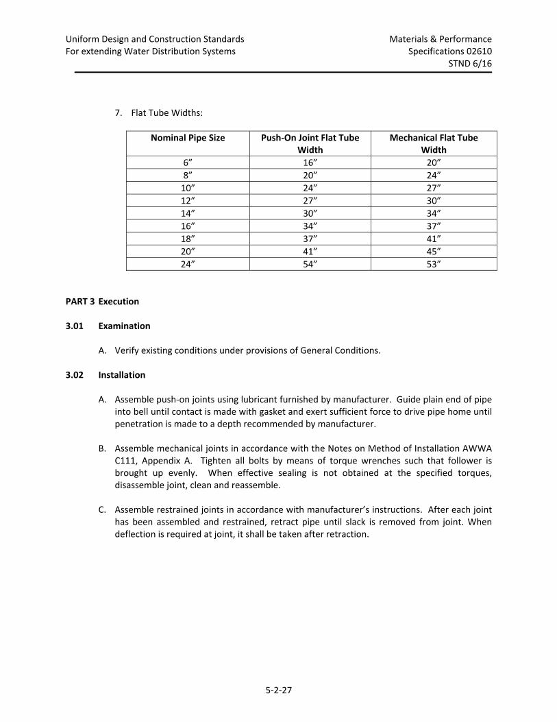
7. Flat Tube Widths:
Nominal Pipe Size Push‐On Joint Flat Tube Width
Mechanical Flat Tube Width
6” 16” 20”
8” 20” 24”
10” 24” 27”
12” 27” 30”
14” 30” 34”
16” 34” 37”
18” 37” 41”
20” 41” 45”
24” 54” 53”
PART 3 Execution
3.01 Examination
A. Verify existing conditions under provisions of General Conditions.
3.02 Installation
A. Assemble push‐on joints using lubricant furnished by manufacturer. Guide plain end of pipe
into bell until contact is made with gasket and exert sufficient force to drive pipe home until penetration is made to a depth recommended by manufacturer.
B. Assemble mechanical joints in accordance with the Notes on Method of Installation AWWA C111, Appendix A. Tighten all bolts by means of torque wrenches such that follower is brought up evenly. When effective sealing is not obtained at the specified torques, disassemble joint, clean and reassemble.
C. Assemble restrained joints in accordance with manufacturer’s instructions. After each joint
has been assembled and restrained, retract pipe until slack is removed from joint. When deflection is required at joint, it shall be taken after retraction.
Uniform Design and Construction Standards Materials & Performance For extending Water Distribution Systems Specifications 02610
STND 6/16
5‐2‐28
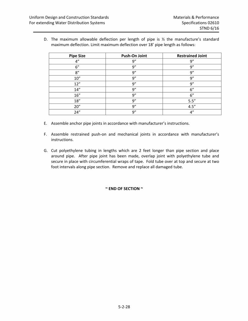
D. The maximum allowable deflection per length of pipe is ½ the manufacture’s standard maximum deflection. Limit maximum deflection over 18’ pipe length as follows:
Pipe Size Push‐On Joint Restrained Joint
4” 9” 9”
6” 9” 9”
8” 9” 9”
10” 9” 9”
12” 9” 9”
14” 9” 6”
16” 9” 6”
18” 9” 5.5”
20” 9” 4.5”
24” 9” 4”
E. Assemble anchor pipe joints in accordance with manufacturer’s instructions.
F. Assemble restrained push‐on and mechanical joints in accordance with manufacturer’s
instructions. G. Cut polyethylene tubing in lengths which are 2 feet longer than pipe section and place
around pipe. After pipe joint has been made, overlap joint with polyethylene tube and secure in place with circumferential wraps of tape. Fold tube over at top and secure at two foot intervals along pipe section. Remove and replace all damaged tube.
~ END OF SECTION ~
Uniform Design and Construction Standards Materials & Performance For Extending Water Distribution Systems Specifications 02630
STND 6/17
5‐2‐29
SECTION 02630
SERVICE CONNECTIONS PART 1 General
1.01 Section Includes
A. Installation of consumer services 1‐inch through 2‐inch.
1.02 Related Sections
A. Section 02225 – Trenching B. Section 02227 – Backfilling
1.03 References A. ANSI/AWWA C800, Underground Service Line Valves and Fittings.
B. ANSI/AWWA C901, Polyethylene (PE) Pressure Pipe and Tubing, 1/2‐Inch through 3‐Inch, for
Water Service. C. ASTM B88 – Standard Specification for Seamless Copper Water Tube.
1.04 Definitions A. Short Side Services: Services connected to a main on same side of street as building being
served.
B. Long Side Services: Services connected to a main on opposite side of street from building being served.
C. Replacements: Service work which includes new corporation stops, curb stops and boxes,
copper or plastic service material equal in size to the existing service but no smaller than 1‐inch nominal diameter.
D. Transfers (short side service only; minimum ¾‐inch nominal copper): Service work which
includes new corporation stops and connection of existing service material to corporation. Couplings are not allowed in short side transfers.
E. Corporation Stop: Valve connecting service line to water main and used to stop flow of
water during installation or maintenance of service line. F. Curb Stop: Valve installed in water service line which connects the Authority’s service to
customer’s service and is operable from the ground surface. Used for stopping the flow of
Uniform Design and Construction Standards Materials & Performance For Extending Water Distribution Systems Specifications 02630
STND 6/17
5‐2‐30
water through the customer service line and installed at the right‐of‐way or easement line unless directed otherwise by the Engineer.
G. Tapping Saddle: Fitting that attaches circumferentially to water main to provide attachment
for a corporation. Used for all 1½‐inch and 2‐inch taps on 4‐inch through 12‐inch ductile and cast iron mains and all size service taps on all sizes of PVC and asbestos cement water mains.
H. Compression Joint: Grip or pack joint for copper and plastic tubing and pack joint with set
screw for galvanized or lead pipe. I. Directional Drilling: Installation by drilling method, using equipment manufactured by
Vermeer or equivalent, where drill head course is directed using a steering mechanism capable of changing direction at any time. Directional drilling operation includes a drilling head capable of auguring, a tracking system to monitor alignment during installation, and the injection of a slurry to fill annular void.
J. Paved Surfaces: Surfaces including, but not limited to, streets, roads, gutters, curbs, sidewalks, asphalt and concrete driveways and asphalt and concrete surfaces.
1.05 Coordination
A. Verify that a notice from Health Department has been received by the Authority stating that
health sample for distribution main is satisfactory.
1.06 Storage and Handling A. Deliver, store, protect and handle products properly to prevent damaging them.
B. Ensure that polyethylene tubing is not dragged over rough ground or installed by pulling
through bore holes containing sharp‐edged material. C. Uncoil tubing and handle without kinking or creasing. Remove all portions of pipe that are
damaged or cut to a depth greater than 10 percent of the wall thickness.
1.07 Submittals A. Product Data: Provide data on service materials.
PART 2 Products
2.01 General Material Requirement A. All material in contact with potable water shall be NSF‐61 certified.
Uniform Design and Construction Standards Materials & Performance For Extending Water Distribution Systems Specifications 02630
STND 6/17
5‐2‐31
2.02 Service Material A. Copper Tubing: 1‐inch minimum nominal diameter, seamless, type K seamless virgin copper
conforming to AWWA C‐800, suitable for underground installation. Copper tubing shall be manufactured to the ASTM B88 standard.
B. Plastic Water Tubing: 1‐inch minimum nominal diameter, virgin, ultra‐high molecular weight polyethylene tubing, type PE4710 (formerly 3408), SDR‐9, conforming to ASTM 2737 NSF‐PW, rated for 250 psi working pressure, outside diameter of 1.125‐inch for 1‐inch tubing, 1.625‐inch for 1½‐inch tubing, and 2.125‐inch for 2‐inch tubing. Plastic water tubing shall bear permanent identification markings that will remain legible during normal handling, storage, installation and service life and that will neither reduce strength nor otherwise damage product. Include the following markings applied at intervals not more than 5 feet:
1. Nominal size.
2. Standard PE code designation.
3. Dimension ratio, diameter base and the word “Tubing”.
4. AWWA pressure class.
5. AWWA designation number, C901.
6. Manufacturer’s name or trademark and production record code.
7. Seal, or mark of testing agency that certified suitability of pipe or tubing material for
potable water products. C. Tracing wire for plastic services: Plastic‐coated 10‐gauge single‐strand copper wire.
2.03 Corporation Stops: 1‐Inch
A. Design
1. Fabricated from no‐lead brass (UNS Copper Alloy C89520 and C89833) in accordance
with chemical and mechanical requirements of ASTM B584 and AWWA C‐800, ball valve, 300 psi working pressure, AWWA CC inlet threads and compression (grip or pack joint), MIP or FIP (as designated by Engineer) outlet. Grip joint shall utilize a one‐piece, combined gasket and metal gripper ring.
B. Manufacturers, Compression Outlet – Services and Sampling Taps 1. A.Y. McDonald: 74701‐BT or 74701B‐22.
2. Ford: FB1000‐3‐Q‐NL, FB1000‐3‐NL, FB1000‐4‐Q‐NL or FB1000‐4‐NL.
Uniform Design and Construction Standards Materials & Performance For Extending Water Distribution Systems Specifications 02630
STND 6/17
5‐2‐32
3. Mueller: B‐25008N or P‐25008N
C. Manufacturers, MIP or FIP Outlet – As directed by Engineer
1. Ford: FB400‐3‐NL, FB400‐4‐NL, FB1600‐3‐NL or FB1600‐4‐NL.
2. Mueller: B‐2996N or B‐20045N.
2.04 Corporation Stops: 1½‐Inch, 1½‐Inch x 2‐Inch, and 2‐Inch
A. Design
1. Fabricated from no‐lead brass (UNS Copper Alloy C89520 and C89833) in accordance
with chemical and mechanical requirements of ASTM B584 and AWWA C‐800, ball valve, 300 psi working pressure, AWWA CC inlet threads and compression (grip or pack joint), MIP or FIP (as designated by Engineer) outlet. Grip joint shall utilize a one‐piece, combined gasket and meter gripper ring.
B. Manufacturers, Compression Outlet – Air Release 1. A.Y. McDonald: 74701‐BT or 74701B‐22.
2. Ford: FB1000‐6‐Q‐NL, FB1000‐6‐NL, FB1000‐67‐NL, FB100‐7‐Q‐NL or FB1000‐7‐NL.
3. Mueller: B‐25008N or P‐25008N.
C. Manufacturers, MIP or FIP Outlet – Services, Blow‐offs
1. Ford: FB400‐6‐NL, FB400‐7‐NL, FB1600‐6‐NL, or FB1600‐7‐NL.
2. Mueller: B‐2996N or B‐20045N.
2.05 Curb Stop: 1‐Inch
A. Design
1. Fabricated from no‐lead brass (UNS Copper Alloy C89520 and C89833) in accordance
with chemical and mechanical requirements of ASTM B584 and AWWA C‐800, ball valve, 300 psi working pressure, compression (grip or pack joint), MIP or FIP inlet and compression (grip or pack joint), MIP or FIP (as designated by Engineer) outlet. Grip joint shall utilize a one piece, combined gasket and metal gripper ring.
B. Manufacturers: Compression by Compression 1. A.Y. McDonald: 76100‐T or 76100‐22.
Uniform Design and Construction Standards Materials & Performance For Extending Water Distribution Systems Specifications 02630
STND 6/17
5‐2‐33
2. Ford: B44‐333‐Q‐NL, B44‐333‐NL, B44‐444‐Q‐NL, or B44‐444‐NL.
3. Mueller: B‐25209N or P‐25209N.
C. Manufacturers: Compression by FIP or MIP
1. Ford: B41‐333‐Q‐NL, B41‐333‐NL, B41‐444‐Q‐NL, B41‐444‐NL, B84‐333‐Q‐NL, B84‐333‐
NL, B84‐444‐Q‐NL, or B84‐444‐NL. 2. Mueller: B‐25172N, P‐25172N, B‐25122N, or P‐25122N.
D. Manufacturers: FIP or MIP by Compression
1. Ford: B41‐333‐Q‐NL, B41‐333‐NL, B41‐444‐Q‐NL, or B41‐444‐NL, B84‐333‐Q‐NL, B84‐
333‐NL, B84‐444‐Q‐NL, or B84‐444‐NL.
E. Manufacturers: FIP or MIP by FIP or MIP 1. A.Y. McDonald: 76101, 76107, or 76107P.
2. Ford: B11‐333‐NL, B11‐444‐NL, B81‐333‐NL, B81‐444‐NL, B88‐333‐NL, or B88‐444‐NL.
3. Mueller: B‐20283N, B‐20285N, or B‐20276N.
2.06 Curb Stops: 1½‐Inch and 2‐Inch
A. Design
1. Fabricated from no‐lead brass (UNS Copper Alloy C89520 and C89833) in accordance
with chemical and mechanical requirements of ASTM B584 and AWWA C‐800, ball valve, 300 psi working pressure, compression (grip or pack joint), FIP or MIP and compression (grip or pack joint), FIP or MIP outlet. Grip joint shall utilize a one piece, combined gasket and metal gripper ring.
B. Manufacturers: Compression by Compression 1. A.Y. McDonald: 76100T or 76100‐22.
2. Ford: B44‐666‐Q‐NL, B44‐666‐NL, B44‐777‐Q‐NL or B44‐777‐NL.
3. Mueller: B‐25209N or P‐25209N.
C. Manufacturers: Compression by FIP or MIP
Uniform Design and Construction Standards Materials & Performance For Extending Water Distribution Systems Specifications 02630
STND 6/17
5‐2‐34
1. Ford: B41‐666‐Q‐NL, B41‐666‐NL, B41‐777‐Q‐NL, B41‐777 ‐NL, B84‐666‐Q‐NL, B84‐666‐NL, B84‐777‐Q‐NL, or B84‐777‐NL.
2. Mueller: B‐25172N, P‐25172N, B‐25122N, or P‐25122N. D. Manufacturer: FIP or MIP by Compression
1. Ford: B41‐666‐Q‐NL, B41‐666‐NL, B41‐777‐NL, B84‐666‐Q‐NL, B84‐666‐NL, or B84‐777‐
NL.
E. Manufacturers: FIP or MIP by FIP or MIP 1. A.Y. McDonald: 76101, 76107, or 76107P.
2. Ford: B11‐666‐NL, B11‐777‐NL, B81‐666‐NL, B81‐777‐NL or B88‐666‐NL, or B88‐777‐NL.
3. Mueller: B‐20283N, B‐20285N, or B‐20276N.
2.07 Curb Boxes: 1¼‐Inch
A. Design
1. Curb Box: Arch pattern extension type with a 5½‐foot bury, 66‐inch maximum extended
length and compressed minimum length of 54‐inch. Bottom section arch must fit 1‐inch ball valve curb stop with a 1¼‐inch upper section.
2. Lids: Cast iron tapped 1¼‐inch with brass pentagon nut plug. “WATER” cast in raised letters on the lid.
3. Curb Rods: Carbon Steel 5/8‐inch outside diameter by 45‐inch or 48‐inch length. “S”
type, bottom clamp/yoke of cast steel, welded into rod and drilled for cotter pin. Brass or copper cotter pin.
B. Manufacturers:
1. Ford: EA2‐55‐50‐45R or EA2‐55‐50‐54R with type PL lid and stationary rod.
2. A.Y. McDonald: 5604, with 5614L lid and 5660 rod.
2.08 Curb Boxes – Enlarged Base
A. Design (Enlarged Base Only)
1. Adaptable with lower section of 1¼‐inch arch pattern curb boxes and sized to fit over
1½‐inch and 2 inch ball curb stops manufactured by A.Y. McDonald, Ford, and Mueller.
Uniform Design and Construction Standards Materials & Performance For Extending Water Distribution Systems Specifications 02630
STND 6/17
5‐2‐35
B. Manufacturers: 1. Bibby‐Ste. Croix: V313.
2. Ford: CB‐7.
2.09 Tapping Saddles for Services on Ductile Iron, Cast Iron, and Asbestos Cement Mains
A. Design
1. Body: Metal alloy red brass 85‐5‐5‐5 (85 percent copper, 5 percent each tin, lead, zinc)
in accordance with chemical and mechanical requirements of ASTM B‐62.
2. Strap/Nuts: Double straps of flattened silicon bronze with strap nuts fabricated of same brass alloy as body.
3. Outlet: AWWA Standard CC female thread.
4. Gasket: Nitrile/BUNA‐N rubber, as per ASTM‐D2000 or EPDM o‐ring.
B. Manufacturers:
1. Ford: 202B.
2. Mueller: BR2B.
3. A.Y. McDonald: 3825.
2.10 Brass Service Couplings A. Design
1. Fabricated from no‐lead brass (UNS Copper Alloy C89520 and C89833) in accordance
with chemical and mechanical requirements of ASTM B584 and AWWA C‐800, with compression (grip or pack joint) inlet and outlet. Grip joint shall utilize a one‐piece, combined gasket and gripper ring.
B. Manufacturers, Compression by Compression: 1. Copper to Copper, Plastic Tubing to Plastic Tubing, or Plastic Tubing to Copper:
a. A.Y. McDonald: 74758T, 74758‐22, 74758‐33, 74758‐22‐33, or 74758T‐33.
b. Ford: C44‐33‐Q‐NL, C44‐33‐NL, C44‐34‐Q‐NL, C44‐34‐NL, C44‐44‐Q‐NL, C44‐44‐NL,
C44‐46‐NL, C44‐66‐Q‐NL, C44‐66‐NL, C44‐77‐Q‐NL, or C44‐77‐NL.
Uniform Design and Construction Standards Materials & Performance For Extending Water Distribution Systems Specifications 02630
STND 6/17
5‐2‐36
c. Mueller: H‐15403N or P‐15403N.
2. Copper or Plastic Tubing to Iron Pipe: a. A.Y. McDonald: 74758T‐55, 74758‐22‐55, 74758‐33‐55, or 74758‐55.
b. Ford: C45‐33‐Q‐NL, C45‐33‐NL, C45‐43‐NL, C45‐44‐NL, C45‐66‐NL, or C45‐77‐NL.
3. Iron Pipe to Iron Pipe:
a. A.Y. McDonald: 74758‐55.
b. Ford: C55‐33‐NL, C55‐44‐NL, C55‐66‐NL, or C55‐77‐NL.
4. Female Iron Pipe Thread to Copper or Plastic Tubing:
a. A.Y. McDonald: 74754T, 74754‐22, 74753T, or 74753‐22.
b. Ford: C14‐33‐Q‐NL, C14‐33‐NL, C14‐43‐Q‐NL, C14‐43‐NL, C14‐44‐Q‐NL, C14‐44‐NL,
C14‐66‐Q‐NL, C14‐66‐NL, C14‐76‐NL, C14‐77‐Q‐NL, C14‐77‐NL, C84‐33‐Q‐NL, C84‐33‐NL, C84‐43‐Q‐NL, C84‐43‐NL, C84‐44‐Q‐NL, C84‐44‐NL, C84‐46‐NL, C84‐66‐Q‐NL, C84‐66‐NL, C84‐67‐NL, C84‐77‐Q‐NL, or C84‐77‐NL.
c. Mueller: H‐15451N or P‐15451N.
2.11 Brass Bushings A. Design
1. Fabricated from no‐lead brass (UNS Copper Alloy C89520 and C89833) in accordance
with chemical and mechanical requirements of ASTM B584 and AWWA C‐800, national pipe threads.
B. Manufacturers: 1. Mueller: 47162N, 47163N, 47164N, 47165N, 47168N, 47169N and 47172N.
2. Ford: C18‐34‐NL, C18‐36‐NL, C18‐37‐NL, C18‐43‐NL, C18‐46‐NL, C18‐47‐NL, C18‐67‐NL or
C18‐76‐NL.
2.12 Steel Service Couplings A. Design
1. Body: Steel, useable length 5‐inch, gasket armored, painted shop coat for repairing iron
or galvanized pipe.
Uniform Design and Construction Standards Materials & Performance For Extending Water Distribution Systems Specifications 02630
STND 6/17
5‐2‐37
B. Manufacturers:
1. Iron Pipe to Iron Pipe:
a. Dresser: Style 90, with armored gaskets (grip coupling).
2.13 Defective Tap Repair Sleeve
A. Design
1. Body: Full circle, entire body, side and keeper bars and fingers made of Type 304
Stainless Steel.
2. Outlet: Type 304 Stainless Steel, AWWA CC.
3. Bolts and Nuts: Type 304 Stainless Steel.
4. Washers: Type 304 Stainless Steel or Polymer.
5. Gaskets: Virgin SBR material, formulated for water use. B. Manufacturers:
1. JCM: 133 or 134
2. Ford: FS‐1 or FS‐2.
3. Cascade: CR‐1 or CR‐2.
4. Romac: SS‐1 or SS‐2.
2.14 Meter Tiles
A. Tile 1. Size
a. 18” nominal diameter for 5/8” and 3/4” meters
2. Material
a. SDR 35 PVC Pipe
Uniform Design and Construction Standards Materials & Performance For Extending Water Distribution Systems Specifications 02630
STND 6/17
5‐2‐38
B. Cover 1. Height
a. Low: 3” – 4” b. High: 9” – 10”
2. Manufacturers – Low
a. Ford: C‐32T Single Lid with Locking Single Hole Electronic Meter Reading Lid b. Mueller: H‐10816‐09 Single Lid with Locking Lid and Single Hole for Electronic Meter
Reading
3. Manufacturers – High a. Ford: W‐32‐T Wabash Double Lid with Single Locking Electronic Meter Reading Hole
Lid b. Mueller: H‐10812‐09 Double Lid with Locking Lid and Single Hole for Electronic
Meter Reading, 11.5” x 18”
PART 3 Execution
3.01 Installation
A. Use direct tapped connections for all 1‐inch taps on ductile iron pipe. Use service saddles
for all 1½‐inch and 2‐inch connections on 12‐inch, or less, ductile iron pipe.
B. Install all service materials, including corporation and curb stop, at a minimum depth of cover of 5.0 feet.
C. Before boring, drilling, missiling, tunneling, or directional drilling for services, verify in
accordance with New York State Industrial Code Rule 753 or as directed by each utility that existing utilities will not be pierced or damaged. Check inverts of all existing utilities including sewers, electric, gas and communication utilities before boring, drilling, missiling, tunneling or directional drilling.
D. Install 1‐inch corporations in upper half of main at a 22½ degree angle with horizontal axis of main and on same side of main as consumer. Install corporation a minimum of 2 feet from any joint or fitting with operating key positioned on side.
E. Connect 1‐inch service material to corporation and gooseneck material downward in such a manner that service material rests firmly on undisturbed soil. Rotate gooseneck slightly to the right (clockwise) of corporation’s centerline. Install gooseneck of sufficient length to
Uniform Design and Construction Standards Materials & Performance For Extending Water Distribution Systems Specifications 02630
STND 6/17
5‐2‐39
preclude any possibility of failure due to settlement. Maintain minimum of 5.0 feet of cover over service gooseneck.
F. Install 1½‐inch and 2‐inch corporations in line with horizontal axis of water main and on
same side of main as consumer. Install corporations a minimum of 2 feet from any joint or fitting with operating key positioned on side. Install two 90 degree brass street ells (I.P. threads) such as that ell attached to corporation will remain stationary while second ell will tighten in the event of settlement. Install a brass female iron pipe thread by compression (copper or plastic) adapter on the second ell.
G. Repair all defective service taps with stainless steel split sleeve repair clamps. Do not re‐tap
main within 12 inches of repair clamp. H. Install copper tubing for all Authority owned portions of a service. In rare cases when HDPE
service tubing is allowed, install all with 10 gauge plastic‐coated copper, single strand, tracing wire wrapped around service. Strip and firmly attach tracing wire to corporation and continue installation above service to coupling for transfers or curb stop and coupling for replacements. Firmly attach wire to coupling. Attach a second wire to the first near curb stop and extend it to the top of the curb box as shown on the Approved Plans. Ensure electrical continuity between the wires.
I. When installing services on a polyethylene encased main, tightly wrap the main with two (2)
layers of 8 mil polyethylene adhesive tape for 12 inches each side of the proposed tap location. After the corporation has been installed, repair any cuts or scrapes to the polyethylene encasement or tape to prevent exposure of water main to the soil. Tape shall conform to section entitled “Ductile Iron Pipe”.
J. Locate new curb boxes on right‐of‐way or easement line. Avoid locating new curb boxes
where sidewalks, pavement will be placed. Avoid locating couplings under pavement or sidewalks unless approved in writing by the Engineer.
K. Install one continuous length of service material from connection to curb box or existing
service to main.
L. Install all services perpendicular to the main, and in a straight line. No horizontal offsets greater than 24 inches in either direction will be allowed unless approved in writing by the Engineer.
If the horizontal offset must be greater than 24 inches, place the new curb box directly opposite the new corporation and offset the service back to the existing customer service.
~ END OF SECTION ~
Uniform Design and Construction Standards Materials & Performance For Extending Water Distribution Systems Specifications 02630
STND 6/17
5‐2‐40
~THIS PAGE INTENTIONALLY LEFT BLANK~
Uniform Design and Construction Standards Materials & Performance For Extending Water Distribution Systems Specifications 02650
STND 6/16
5‐2‐41
SECTION 02650
WATER MAIN CONNECTIONS PART 1 General
1.01 Section Includes
A. Installing Tapping Sleeves and Valves
B. Installing Ductile Iron Pipe, Anchor Tees, and Valves
1.02 Related Specifications A. Section 02610 – Ductile Iron Pipe
B. Section 02655 – Water System Appurtenances C. Section 02660 – Water Valves
1.03 References A. ANSI/AWWA C110 – Ductile Iron and Gray Iron Fittings, 3 Inch through 48 Inch, for Water
and Other Liquids.
B. ANSI/AWWA C111 – Rubber Gasket Joints for Ductile Iron and Gray Iron Pressure Pipe and Fittings.
C. ANSI/AWWA C153 – Ductile Iron Compact Fittings, 3 Inch through 24 Inch. D. ANSI/AWWA C500 – Gate Valves, 3 Inch through 48 Inch NPS, for Water and Sewage
Systems.
1.04 Submittals A. Product Data: Provide data on tapping sleeves, valves, pipe, couplings and anchor tees.
B. Manufacturer’s Certificate: Certify that products meet or exceed specified requirements.
PART 2 Products
2.01 General Material Requirements A. All valves and fittings shall be NSF‐61 Certified for contact with drinking water.
Uniform Design and Construction Standards Materials & Performance For Extending Water Distribution Systems Specifications 02650
STND 6/16
5‐2‐42
2.02 Tapping Sleeves A. Specifications for Ductile or Cast Iron Sleeves
1. Sleeve: ANSI/AWWA C110.
2. Joints: ANSI/AWWA C111, mechanical joint with 125 pound tapping flange, rubber
gasket.
3. Bolts: Cor‐Ten or Usalloy. B. Specifications for Stainless Steel Sleeves
1. Sleeve: 18‐8 Type 304 stainless steel.
2. Flange: CF8 cast stainless steel.
3. Bolts: Type 304 stainless steel.
4. Gasket: Full circumferential gasket.
C. Manufacturers for Ductile or Cast Iron Tapping Sleeves
1. US Pipe / Mueller: #H‐615.
2. American: Product #2800.
3. McWane Group: Tyler Compact.
D. Manufacturers for Stainless Tapping Sleeves.
1. Power Seal: #3490‐AS.
2. Ford: #FTSS.
3. Cascade: #CST‐EX.
4. Mueller: #H‐304SS.
5. JCM: #432 SS (not approved on mains to be pressure tested over 150 PSI).
2.03 Valves and Tapping Valves
A. Conform to Specification 02660.
Uniform Design and Construction Standards Materials & Performance For Extending Water Distribution Systems Specifications 02650
STND 6/16
5‐2‐43
2.04 Ductile Iron Pipe A. Conform to Specification 02610.
2.05 Tees, Anchor Tees, and Couplings
A. Conform to Specification 02655.
PART 3 Execution
3.01 Preparation A. Excavate existing main at tie‐in location in accordance with Specification 02225.
B. Verify actual pipe size, material and tap location. C. Remove dirt and scale on exterior of existing main.
3.02 Installation – Tapping Sleeve and Valve A. Schedule tap with the Authority two (2) working days in advance through the Distribution
System Supervisor.
B. Swab disinfect water main, tapping sleeve and valve. Install tapping sleeve and valve in accordance with the manufacturer’s instructions. Maintain a 3 foot separation from ends of sleeve to adjacent joints or fittings.
C. Verify with the Authority in advance of tap that excavation provided is of sufficient size for
tapping operations. If a larger excavation is required, excavate as directed by Engineer. Excavate and provide sheeting and shoring and access to excavation in accordance with OSHA regulations.
D. Provide backhoe and Operator to assist Tapping Crew during tapping work. Provide flagmen
and barricades when necessary. Operator of backhoe shall assist Tapping Crew with installation and removal of tapping machine.
E. Fill void around tapping sleeve and valve with potable water. Tapping Crew shall perform an
air over water pressure test on the installed tapping sleeve and valve. Sleeve and valve shall maintain 150 PSI for five (5) minutes with no leakage.
F. When tapping sleeve or tapping valve leaks, it is the sole responsibility of the Contractor to
remove, reinstall and replace, if necessary, tapping sleeve or tapping valve. Reinstalled or replaced sleeves and valves shall be retested until they achieve satisfactory test results.
G. Backfill excavation in accordance with Specification 02225.
Uniform Design and Construction Standards Materials & Performance For Extending Water Distribution Systems Specifications 02650
STND 6/16
5‐2‐44
H. Install valve box in accordance with Specification 02660.
3.03 Installation – Cut‐In Tee and Valve A. Schedule water main shutdown with the Authority.
B. Excavate existing water main at the tie‐in location. Prevent undermining of existing main
outside of replacement limits. C. Confirm water main has been turned off. D. Cut and remove existing water main at tie‐in location. The minimum length of pipe
removed shall be the laying length of the tee plus 3 feet on either side of tee. When existing pipe joints fall within 3 feet of the cut points (located as specified above), joints shall also be removed and additional ductile iron pipe installed.
E. Swab disinfect pipe and fittings to be installed. F. Install couplings, ductile iron pipe, anchor tee and valve. G. Assist the Authority in returning main to service. H. Verify that installed pipe and fittings do not leak. I. Backfill excavation in accordance with Section 02225. J. Install valve box in accordance with Section 02660.
~ END OF SECTION ~
Uniform Design and Construction Standards Materials & Performance For Extending Water Distribution Systems Specifications 02655
STND 6/16
5‐2‐45
SECTION 02655
WATER SYSTEM APPURTENANCES PART 1 General
1.01 Section Includes
A. Hydrants
B. Hydrant Extensions C. Couplings and Flanged Coupling Adapters D. Permanent Manual Air Releases & Blow‐Offs E. Automatic Air Releases
1.02 Related Sections A. Section 02600 – Pipe Installation
B. Section 02610 – Ductile Iron Pipe C. Section 02630 – Service Connections D. Section 02660 – Water Valves
1.03 References A. ANSI/AWWA C110 – Ductile Iron and Gray Iron Fittings, 3” through 48”, for Water and Other
Liquids.
B. ANSI/AWWA C111 – Rubber Gasket Joints for Ductile Iron and Gray Iron Pressure Pipe and Fittings.
C. ANSI/AWWA C219 – Bolted, Sleeve‐type Couplings for Plain End Pipe. D. ANSI/AWWA C502 – Dry Barrel Fire Hydrants. E. ANSI/AWWA C512 – Air Release, Air Vacuum, and Combination Air Valves for Waterworks
Service. F. ASTM A53 – Standard Specification for Pipe, Steel, Black and Hot Dipped, Zinc Coated
Welded and Seamless.
Uniform Design and Construction Standards Materials & Performance For Extending Water Distribution Systems Specifications 02655
STND 6/16
5‐2‐46
G. ASTM A536 – Standard Specification for Ductile Iron Castings.
1.04 Definitions A. Limited Range: A coupling that will fit only Class A, B, C, or D cast iron pipe, Class 51‐56
ductile iron pipe, or Class 100 or 150 rough barrel asbestos cement pipe. 1.05 Submittals
A. Provide product data as required.
PART 2 Products
2.01 General Material Requirement A. All materials in contact with potable water shall be NSF‐61 Certified.
2.02 Hydrants and Hydrant Branches
A. Hydrants
1. Standard:
a. ANSI/AWWA C502 – Dry Barrel Fire Hydrants
2. 5‐1/4 inch valve opening.
3. 5‐1/2 foot bury for a standard hydrant and 6‐1/2 foot bury for a blow‐off hydrant.
4. Counterclockwise direction of opening.
5. OSHA safety yellow paint conforming to Federal lead standards.
6. Pentagon‐shaped operating nuts, 1‐1/2 inch point to flat with weather cap or shield.
7. “O” Ring packing.
8. Bronze to bronze seat rings.
9. Nozzles
a. 1 – 4‐1/2 inch inside diameter with 5.7609 inch outside diameter, male, 4 threads
per inch.
Uniform Design and Construction Standards Materials & Performance For Extending Water Distribution Systems Specifications 02655
STND 6/16
5‐2‐47
b. 2 – 2‐1/2 inch inside diameter with 3.0686 inch outside diameter, male, 7‐1/2 threads per inch.
c. Mechanically attached nozzles with National Standard Threads.
d. Threaded female caps without chains.
e. Orientation: Two smaller nozzles 180⁰ apart with large nozzle located equidistant
between them.
10. 6 inch mechanical joint inlet with connecting gland, mechanical joint gasket and Core‐Ten or Usalloy “T” head bolts.
11. Manufacturers
a. Mueller: Centurion.
b. Clow Eddy: #F‐2640.
c. Kennedy Guardian: #K‐81‐D.
d. U.S. Pipe: Sentinel 250™ or Metropolitan ® M‐94. B. Anchor Pipe & Mechanical Joint Fittings
1. In accordance with Specification 02610.
C. Anchoring Tees, Mechanical Joint
1. Standard
a. ANSI/AWWA C110 – Ductile Iron and Gray Iron Fittings, 3 Inch Through 48 Inch, for
Water and Other Liquids.
2. Manufacturers
a. McWane Group (Tyler, Union and Clow).
b. Griffin / US Pipe D. Anchoring Elbows, Mechanical Joint
1. Manufacturers
a. McWane Group (Tyler, Union and Clow).
Uniform Design and Construction Standards Materials & Performance For Extending Water Distribution Systems Specifications 02655
STND 6/16
5‐2‐48
E. Guard Valve 1. 6 inch gate valve in accordance with Specification 02660.
F. Cement Block
1. Hydrants: Solid 8”x8”x16”.
2. Guard Valve: See Section 02660.
G. Select Fill for Drain
1. Type 7
2.03 Straight & Transition Couplings
A. Standards
1. ANSI/AWWA C111 – Rubber Gasket Joints for Ductile Iron and Gray Iron Pressure Pipe.
2. ANSI/AWWA C219 – Bolted, Sleeve‐Type Couplings for Plain End Pipe.
3. ASTM A36 – Standard Specification for Carbon Structural Steel.
4. ASTM A242 – Standard Specification for High‐Strength, Low‐Alloy Structural Steel.
5. ASTM A304 – Standard Specification for Carbon and Alloy Steel Bars, Subject to End‐
Quenched Hardenability Requirements.
6. ASTM A325 – Standard Specification for Structural Bolts, Steel, Heat Treated, 120/105 KSI Minimum Tensile Strength.
7. ASTM A307 – Standard Specification for Carbon Steel Bolts and Studs.
8. ASTM A513 – Standard Specification for Electric‐Resistance‐Welded Carbon and Alloy
Steel Mechanical Tubing.
9. ASTM A536 – Standard Specification for Ductile Iron Casting.
10. ASTM A563 – Standard Specification for Carbon and Alloy Steel Nuts.
11. ASTM A635 – Standard Specification for Steel, Sheet and Strip Heavy‐Thickness Coils, Hot‐Rolled, Carbon, Structural, High‐Strength Low‐Alloy and High‐Strength Low‐Alloy with Improved Formability, General Requirements.
B. All ductile iron or steel.
Uniform Design and Construction Standards Materials & Performance For Extending Water Distribution Systems Specifications 02655
STND 6/16
5‐2‐49
C. Manufacturers – Straight Couplings
1. Smith Blair: #441, 2 inch through 12 inch, Limited Range only.
2. Smith Blair: #441, 16 inch and greater.
3. Dresser: #138, 4 inch through 12 inch.
4. Dresser: #38, 16 inch and above.
5. JCM: #210, 2 inch through 12 inch.
6. JCM: #201, 16 inch and greater.
7. Ford: #FC1, 2 inch through 12 inch. D. Manufacturers – Transition Couplings
1. Dresser: #162, 4 inch through 12 inch.
2. Dresser: #62, 16 inch through 30 inch.
3. Smith Blair: #441, Omni, 4 inch through 12 inch.
4. Smith Blair: #415, 16 inch through 30 inch.
5. JCM: #212, 4 inch through 12 inch.
6. Ford: #FC‐2, Steel, 4 inch through 24 inch.
E. Bitumastic
1. Manufacturer
a. Carboline: Bitumastic® 300 M.
F. Polyethylene Encasement
1. In accordance with Specification 02610.
2.04 Flanged Coupling Adapters
A. Body: Ductile iron as per ASTM A536.
B. End Ring: Ductile iron as per ASTM A536.
Uniform Design and Construction Standards Materials & Performance For Extending Water Distribution Systems Specifications 02655
STND 6/16
5‐2‐50
C. Gasket: SBR or Buna‐N. D. Coating: Fusion‐bonded epoxy. E. Flange o‐ring: Buna‐N. F. No anchor studs. G. Manufacturers:
1. Ford: FCA
2. Smith‐Blair: 913 Flanged Coupling Adapter
2.05 Permanent Manual Air Releases & Blow Offs (1 Inch and 2 Inch) A. Corporations (1 Inch & 2 Inch)
1. In accordance with Specification 02630.
B. Copper Tubing – Permanent Manual Air Releases (1 Inch)
1. In accordance with Specification 02630.
C. Pipe & Fittings – Blow‐Offs (2 Inch)
1. Brass (bronze)
a. 125 pounds, IPS threads.
b. Standards
1. Red Brass Pipe: ASTM B43. 2. Fittings: ASTM B584.
3. I.P.S. Threads.
D. Curb Stops
1. Manufacturers – Permanent Manual Air Releases (1 Inch)
a. Ford: B44‐444SW‐G‐NL.
2. Manufacturers – Blow‐Offs (2 Inch)
Uniform Design and Construction Standards Materials & Performance For Extending Water Distribution Systems Specifications 02655
STND 6/16
5‐2‐51
a. Ford: B44‐777SW‐NL.
E. Curb Rods & Boxes (1‐1/4 Inch & 2 Inch)
1. In accordance with Specification 02630.
F. Couplings
1. Manufacturers – Permanent Manual Air Releases (1 Inch)
a. In accordance with Specification 02630.
2. Manufacturers – Blow‐Offs (2 Inch)
a. Dresser: Product #90.
G. Caps
1. Manufacturers – Permanent Manual Air Releases (1 Inch)
a. Mueller: H‐15451 with H‐10035 brass plug.
2. For Blow Offs (2 Inch) use a brass cap with female I.P.S. threads.
H. M.J. Plugs and Tapped Tees
1. In accordance with Section 02610.
I. Tapped Tees – Blow‐Offs (2 Inch)
1. Manufacturers
a. Tyler Union: Tapped Tee.
2.06 Automatic Air Releases
A. Automatic Air Release Valve (Small Orifice)
1. Standard: AWWA C512 – Air Release, Air Vacuum and Combination Air Valves for
Waterworks Service.
2. Valve (Inlet) & Orifice Size: As indicated on the Approved Plans.
3. Body Inlet/Cover Outlet Configuration: Threaded.
Uniform Design and Construction Standards Materials & Performance For Extending Water Distribution Systems Specifications 02655
STND 6/16
5‐2‐52
4. Materials
a. Body & Cover – Gray cast iron (ASTM A126, Class B) or ductile iron (ASTM A536, Grade 65‐45‐12).
b. Float, Trim & Lever Mechanism – Stainless steel.
c. Valve Seats – Elastomeric materials.
5. Working Pressure: 150 PSI, unless otherwise noted.
6. Test Pressure:
a. Shell – Minimum of 1.5 times the working pressure.
b. Seat‐ Zero leakage at a minimum pressure of 20 PSI and at a maximum pressure of 1.5 times the working pressure.
c. Float – Minimum of 1000 PSI.
7. Manufacturers:
a. Val‐Matic Corporation.
b. GA Industries.
B. Corporations
1. In accordance with Specification 02630 and as shown on the Approved Plans.
C. Brass (Bronze) Pipe and Fittings
1. In accordance with Specification 02630.
D. Vault & Other Materials
1. As specified in the pertinent sections of the Approved Plans and Specifications.
PART 3 Execution
3.01 Hydrants A. Request final field location of the proposed hydrant from Engineer just before installation.
Uniform Design and Construction Standards Materials & Performance For Extending Water Distribution Systems Specifications 02655
STND 6/16
5‐2‐53
B. Install only anchor pipe and mechanical joint fittings from hydrant tee to hydrant in order to provide a mechanically restrained hydrant branch.
C. For blow‐off hydrants, rotate hydrant anchor tee outlet 45 degrees below the horizontal axis
of the water main. Install a 45 degree mechanical joint bend on the hydrant tee. D. Maintain 24 inches minimum separation between guard valve and hydrant. E. Install hydrant vertical and plumb with the casting ring or mark (located just below the
breakaway flange on the hydrant barrel) at grade. When there is no casting ring or mark, install hydrant with breakaway flange 2‐1/2 inches above grade.
F. Install an 8” x 16” x 8” solid concrete building block and, as necessary, smaller solid concrete
blocks between hydrant base and undisturbed soil at trench bottom. G. Install No. 1 washed stone (Type 7 Select Fill) at bottom of the excavation along the entire
width and length of trench and to the base of the guard valve box as shown on the Approved Plans. Install polyethylene encasement on top of Select Fill.
H. Install hydrant extensions on hydrants when the distance between the centerline of the 4‐
1/2 inch nozzle and finished grade (the “nozzle height”) is less than 18 inches. Install appropriate hydrant extension to ensure that the “nozzle height” is not greater than 24 inches. Hydrant extensions shall be paid for under the appropriate payment item of the Bid.
I. Remove all nozzle cap chains. J. When installation and clean up are complete, remove all loose scale and foreign matter on
the hydrant and paint with one coat of paint. K. Plug hydrant weep holes when ground water is encountered within 7 feet of finished grade.
3.02 Couplings A. Install in accordance with the manufacturer’s instructions.
B. Completely coat coupling and bolts with bitumastic. C. Wrap coupling with polyethylene tubing and secure in accordance with Specification 02610.
3.03 Permanent Manual Air Releases. A. Install corporation on top of water main. B. Install as shown on Approved Plans.
Uniform Design and Construction Standards Materials & Performance For Extending Water Distribution Systems Specifications 02655
STND 6/16
5‐2‐54
3.04 Blow‐Offs A. Install taps for blow‐offs in the lower half of water main at a 45 degree angle with the
horizontal axis of the main. On dead end mains, install tap 1.5’ from end of pipe.
B. Install as shown on Approved Plans.
3.05 Automatic Air Releases A. Install corporation on top of water main.
B. Install as shown on Approved Plans.
3.06 Final Adjustments A. Adjust all hydrants, valve boxes, curb boxes, manhole covers, and other facilities to finished
grade.
~ END OF SECTION ~
Uniform Design and Construction Standards Materials & Performance For Extending Water Distribution Systems Specifications 02660
STND 6/16
5‐2‐55
SECTION 02660
WATER VALVES PART 1 General
1.01 Section Includes
A. Specifications for and installation of buried service main line and tapping valves
1.02 Related Sections
A. Section 02600 – Pipe Installation
B. Section 02610 – Ductile Iron Pipe C. Section 02650 – Water Main Connections D. Section 02655 – Water System Appurtenances
1.03 References A. ANSI/AWWA C104 – Cement Mortar Lining for Ductile Iron Pipe and Fittings for Water.
B. ANSI/AWWA C110 – Ductile Iron and Gray Iron Fittings, 3 Inch through 48 Inch for Water
and Other Liquids. C. ANSI/AWWA C111 – Rubber Gasket Joints for Ductile Iron Pressure Pipe and Fittings. D. ANSI/AWWA C500 – Metal Seated Gate Valves for Water Supply Service. E. ANSI/AWWA C504 – Rubber Seated Butterfly Valves. F. ANSI/AWWA C509 – Resilient Seated Gate Valves, 3 Inch through 48 Inch NPS, for Water
and Sewage Systems. G. ANSI/AWWA C515 – Reduced Wall, Resilient Seated Gate Valves for Water Supply Service. H. ANSI/AWWA C550 – Standard for Protective Epoxy Interior Coatings for Valves and
Hydrants.
1.04 Submittals A. Product Data: Provide data on valves and accessories.
B. Manufacturer’s Certificate: Certify that products meet or exceed specified requirements.
Uniform Design and Construction Standards Materials & Performance For Extending Water Distribution Systems Specifications 02660
STND 6/16
5‐2‐56
1.05 Delivery, Storage and Handling
A. Deliver and store valves, 16 inch and larger, in shipping containers with labeling in place.
PART 2 Products
2.01 General Material Requirements A. All valves shall be NSF‐61 certified for contact with drinking water.
2.02 Resilient‐Seated Gate Valves, 3 Inch through 20 Inch Diameter (Including Tapping Valves)
A. Standards
1. Valves 4” – 12”: ANSI/AWWA C509 – Including factory production testing, except for
rated working pressure.
2. Valves 14” – 20”: ANSI/AWWA C515 – Including factory production testing, except for rated working pressure.
B. Rated Working Pressure
1. 250 PSI.
C. Design Options
1. Non‐rising stem.
2. Counterclockwise direction of opening, except all valves 12 inch and smaller installed in
the Town of Webster shall be clockwise direction of opening and all valves installed in the Town of Henrietta shall be clockwise direction of opening.
3. Mechanical joint ends except for tapping valves which shall be mechanical joint by
tapping flange.
4. Double O ring stem seal.
5. 2 inch square operating nut.
6. Fusion epoxy coated interior and exterior surfaces.
7. 304 stainless steel body and bonnet bolts. D. Manufacturers
Uniform Design and Construction Standards Materials & Performance For Extending Water Distribution Systems Specifications 02660
STND 6/16
5‐2‐57
1. Clow
a. MJ x MJ, 4” – 12”; Model 2639 or 2640, Figure F6100.
b. MJ x Tapping Flange, 4” – 12”; Model 2639 or 2640, Figure F6114.
c. MJ x MJ, 14” – 20”; Model 2638, Figure F6100.
d. MJ x Tapping Flange, 14” – 20”; Model 2638, Figure F6114.
2. U.S. Pipe
a. MJ x MJ, 4” – 12”: A‐USP2‐20.
b. MJ x MJ, 14” – 20”: A‐USP1 – 20.
c. MJ x TF, 4” – 12”: T‐USP0‐16.
d. MJ x TF, 14” – 16”: T‐USP1‐16.
3. Kennedy
a. MJ x MJ, 4” – 12”: Style 8571SS.
b. MJ x MJ, 14” – 16”: Style 7571SS.
c. MJ x TF, 4” – 12”: Style 8950SS.
d. MJ x TF, 14” – 16”: Style 7950SS.
4. Mueller
a. MJ x MJ, 4” – 12”: A2360.
b. MJ x MJ, 14” – 20”: A2361.
c. MJ x TF, 4” – 12”: T2360.
d. MJ x TF, 14” – 20”: T2361.
2.03 Rubber Seated Butterfly Valves for Buried Service
A. Standards
1. ANSI/AWWA C504, including factory testing.
Uniform Design and Construction Standards Materials & Performance For Extending Water Distribution Systems Specifications 02660
STND 6/16
5‐2‐58
B. Design Options
1. Mechanical joint ends.
2. Pressure Class 150B, unless specified otherwise.
3. O ring shaft seals.
4. Alloy cast iron disc.
5. 18‐8 Type 304 stainless steel shaft.
6. 2 inch square operating nut.
7. Counterclockwise direction of opening.
8. Buried manual operator.
9. 304 stainless steel body and bonnet bolts.
C. Manufacturers
1. Henry Pratt Company.
2. Val‐Matic.
3. Mueller
4. Kennedy.
2.04 Extension Stems
A. Standards
1. Stem Material: Fiberglass, 2 inch O.D. square tubing.
2. End Unit Material: PVC, with centering device on upper end unit.
3. Adhesive: Hard drying, clear silicone.
B. Manufacturers
1. Pipeline Products: FPU.
Uniform Design and Construction Standards Materials & Performance For Extending Water Distribution Systems Specifications 02660
STND 6/16
5‐2‐59
2.05 Valve Boxes A. Standards
1. Boxes shall be 5‐1/4 inch diameter.
2. Boxes shall be screw type.
3. Boxes shall lock into base sections.
4. All sections shall be interchangeable with old Buffalo Foundry boxes, Style #5001.
5. Boxes shall be coated with a petroleum asphaltic material.
6. All box tops shall have the word “Water” cast into them.
B. Manufacturers – Gate and Tapping Valve Boxes
1. Bibby‐Ste‐Croix
a. Base: #6 7341 (8” and smaller valves) or #160 oval base V870 (10” to 16” valves).
b. Mid Section: 7345 #59 or V817 #61.
c. Top Section: V733, V734 or V735.
d. Risers: V829, V831, V832 or V833.
e. Covers: V878.
2. Bingham & Taylor
a. Base: #6 Round Base (8” and smaller gate valves) or #160 oval base V870 (10”
through 16” gate valves).
b. Mid Section: Figure 4905‐X.
c. Top Section: Series Figure 4906.
d. Risers: Series Figure 6016‐B.
e. Covers: Figure 4905‐L15. C. Manufacturers – Butterfly Valve Boxes
1. Bibby‐Ste‐Croix
Uniform Design and Construction Standards Materials & Performance For Extending Water Distribution Systems Specifications 02660
STND 6/16
5‐2‐60
a. Regular Valve Box: 2 Piece Screw Type, B‐5003.
b. Extensions: Screw Type, B‐5050.
c. Risers: B‐5180, B‐5181 or B‐5182.
d. Covers: “Water”, B‐5160.
2.06 Cement Block
A. Solid, 4” x 8” x 16”
PART 3 Execution
3.01 Installation A. Install valve on cement block support so that valve is supported independently of pipeline.
B. Install valve in accordance with manufacturer’s recommendations. C. Place and compact Type 7 Select Fill around valve up to base of valve box. Install
polyethylene encasement on top of Select Fill. D. Center and plumb valve box over operating nut. Set box cover flush with finished grade. E. Install valve stem extensions when required.
1. Install extension stems on valves when the distance between the valve operating nut and finished grade is greater than 5‐1/2 feet.
2. Maintain a distance between 5‐1/2 feet and 3 feet from top of extension stem and finished grade.
3. Field cut fiberglass tubing to required length.
4. Apply silicone to inner groove of end units and install end units on tubing.
5. Apply silicone to lower end unit and install on valve nut.
~ END OF SECTION~

Uniform Design and Construction Standards Materials & Performance For Extending Water Distribution Systems Specifications 02670
STND 6/16
5‐2‐61
SECTION 02670
BORES PART 1 General
1.01 Section Includes
A. Casing Pipe Installation by Bore Method
B. Casing Pipe Installation by Open‐Cut Method C. Bore Without Casing Pipe D. Tunneling
1.02 Related Sections A. Section 02225 – Trenching B. Section 02227 – Backfilling C. Section 02229 – Rock Removal
1.03 References A.
Nominal Casing Diameters
ASTM Standard Specifications
4” through 92” A‐139 “Electric‐Fusion (Arc) Welded Steel Pipe” (Factory hydrostatic tests are not required.)
4” through 26” A‐53 “Type‐E Electric Resistance Welded” (Factory hydrostatic tests are not required.)
1.04 Qualifications
A. Boring Firm: Company specializing in performing the work of this section with minimum 3
completed installations and 2 years documented experience.
PART 2 Products
2.01 Materials A. Welded steel casing pipe with 3/8” thick walls.
Uniform Design and Construction Standards Materials & Performance For Extending Water Distribution Systems Specifications 02670
STND 6/16
5‐2‐62
B. Install only new pipe that has smooth surfaces which are uniform and free of bulges, dents or warping throughout entire length. Furnish finished lengths of pipe with beveled‐cut ends to facilitate proper welding of transverse joints.
C. Furnish casing pipe that has been joined together circumferentially, either in shop or in the
field, by the continuous butt welding method, performed in accordance with procedures, required materials and equipment specified by the American Welding Society. Utilize only experienced welders, qualified in accordance with the requirements of the latest edition of “Standard Qualification Procedure” issued by the American Welding Society.
D. Shop coat all surfaces (exterior and interior) of the pipe (except for a 1” wide circumferential
band at ends of pipe lengths which are to be jointed by field welding) with one coat of Carboline Bitumastic 300M or Tnemec Series 46‐465 H.H. Tnemecol. Remove all scale and rust with a wire brush. Wipe clean and dry all surfaces prior to painting. Paint field weld areas with one coat of bitumastic.
E. Casing spacers constructed of 14 gauge carbon steel (with thermoplastic powder coating) or
stainless steel with PVC or EPDM liners, or high‐density polyethylene. Liners are not required for high‐density polyethylene casing spacers. Runners constructed of UHMW polymer, glass reinforced plastic, or high‐density polyethylene spaced equally around the circumference to maintain bell clearance on all sides. Runners to be equal length to assure water main is centered in casing pipe.
F. Type 5 Select Fill. G. A larger size casing may be utilized for convenience or ease of construction, if approved by
the Engineer and permitted by owner of highway, including any additional requirements which may be imposed by said owner. Use of a larger size casing will not result in additional costs to the Authority.
PART 3 Execution
3.01 Preparation A. Identify required lines, levels, contours, and datum.
B. Lay out necessary excavations and tunnel or bore locations to determine clearances or
conflicts with existing structures. C. Protect structures near the bore or tunneling work from damage. D. Verify in accordance with New York State Industrial Code Rule 753 or as directed by each
utility owner that existing utilities will not be hit or damaged by bore.
Uniform Design and Construction Standards Materials & Performance For Extending Water Distribution Systems Specifications 02670
STND 6/16
5‐2‐63
E. Place pipe onto ground within right of way or easements or other approved locations by means of machinery using slings or other approved methods. Do not dump pipe from trucks.
3.02 Casing Pipe Installations by Bore Method
A. Install casing pipe by boring and jacking. Prevent unsupported excavation ahead of casing
pipe.
B. Select a cutting head suitable for soil being bored and capable of preventing free flow of soft or poor material.
C. Weld entire circumference of each joint of casing pipe as each section is installed. D. Install restrained joint ductile iron water main by joining and sliding ahead each pipe length
by length into casing. Furnish all necessary casing spacers, shims, concrete leveling courses, guide tracks, tools and other equipment which are required to place pipe into casing true to grade and line. Adequately support water main with casing spacers installed within casing to prevent any possible deflection or damage during and after installation. Water main shall be inspected for alignment and grade. Restrained joint water main shall extend a minimum of 5 feet beyond each end of casing.
E. Install in accordance with manufacturers assembly and installation instructions. Confirm the
number of casing spacers installed is adequate based on manufacturer’s allowable max load. F. When water main has been successfully installed in casing pipe and pressure tested, fill
space between outside of water main and casing pipe with Type 5 Select Fill. Pump Select Fill into casing space from one end of casing. Pump until Select Fill is evident at other end of casing and all visible voids are filled.
G. Use of water or other liquids to facilitate casing installation and spoil removal is prohibited.
3.03 Casing Pipe Installation by Open Cut Method A. Install pipe as per Section 3.01 by open cutting instead of boring.
3.04 Boring Without Casing or Tunneling
A. Equally spilt length of bore from the center of each utility pole, tree, planting or structure to
be bored or tunneled.
B. Maintain the minimum diameter and excavation required for insertion of water pipeline.
Uniform Design and Construction Standards Materials & Performance For Extending Water Distribution Systems Specifications 02670
STND 6/16
5‐2‐64
C. Do not ram pipe or casing pipe instead of boring. D. Place Type 5 Select Fill in all voids between water pipeline and bore wall. Fill voids from one
end until select fill is evident at the other end.
~ END OF SECTION ~
Uniform design and Construction Standards Materials & Performance For Extending Water Distribution Systems Specifications 02671
STND 6/16
5‐2‐65
SECTION 02671
HORIZONTAL DIRECTIONAL DRILLING PART 1 General
1.01 Section Includes
A. Horizontal directional drilling (HDD) method of installation for restrained joint ductile iron
pipe.
1.02 Related Sections A. Section 02225 – Trenching B. Section 02227 – Backfilling C. Section 02230 – Select Fill D. Section 02229 – Rock Removal E. Section 02600 – Pipe Installation F. Section 02610 – Ductile Iron Pipe G. Section 02675 – Pressure Testing, Flushing, Disinfecting, and Health Sampling of Water
Mains H. Section 02700 – Concrete Thrust Blocks
1.03 References A. ASTM F 1962‐05 – Standard Guide for Use of Maxi‐Horizontal Directional Drilling for
Placement of Polyethylene Pipe or Conduit Under Obstacles Including River Crossings.
B. ANSI/AWWA C104 – Cement Mortar Lining for Ductile Iron Pipe and Fittings for Water. C. ANSI/AWWA C105 – Polyethylene Encasement for Ductile Iron Pipe Systems. D. ANSI/AWWA C110 – Ductile Iron and Gray Iron Fittings, 3‐inch through 48‐inch, for Water
and Other Liquids. E. ANSI/AWWA C111 – Rubber Gasket Joints for Ductile Iron Pipe and Fittings. F. ANSI/AWWA C150 – Thickness Design of Ductile Iron Pipe.
Uniform design and Construction Standards Materials & Performance For Extending Water Distribution Systems Specifications 02671
STND 6/16
5‐2‐66
G. ANSI/AWWA C151 – Ductile Iron Pipe, Centrifugally Cast, for Water. H. ANSI/AWWA C153 – Ductile Iron Compact Fittings for Water Service. I. ANSI/AWWA C600 – Installation of Ductile Iron Water Mains and Their Appurtenances.
1.04 Qualifications A. HDD Contractor: Company specializing in performing the work of this Section with
minimum 5 completed installations and 2 years documented experience. Documentation shall include references with name of owner, owner’s representative, phone numbers, length of bore, diameter of bore, and project location.
PART 2
2.01 General Material Requirements
A. All pipe fittings, grout and drilling fluids shall be NSF 61 certified for contact with drinking
water.
B. Pipe shall conform with Section 02610.
PART 3 Execution
3.01 Preparation A. Identify required lines, levels, contours, and datum.
B. Determine locations and depths of existing utilities. C. Layout necessary excavations and entry and exit point pit locations to determine clearances
or conflicts with existing structures. Determine outer boundaries of available work area as defined by either easements or rights‐of‐way.
D. Protect structures and existing utilities near the drilling work from damage. E. Verify in accordance with New York State Industrial Code Rule 753 or as directed by each
utility owner that existing utilities will not be hit or damaged by bore. F. Place pipe onto ground within right‐of‐way or easement or other approved locations by
means of machinery using slings or other methods. Do not dump pipe from trucks.
Uniform design and Construction Standards Materials & Performance For Extending Water Distribution Systems Specifications 02671
STND 6/16
5‐2‐67
3.02 Installation A. Use drilling equipment compatible with thrust and torque required for drilling, reaming and
pulling back operation.
B. Install water mains as shown on Approved Plans. C. Install only restrained joint pipe by HDD. D. Maintain minimum depth of cover and separation from existing utilities as specified in
Section 02600 – Pipeline Installation. E. Limit longitudinal pull on water main not to exceed 90% of the maximum pulling force
specified by the pipe manufacturer. Continuously monitor longitudinal pulling forces during pipe pull back.
F. The vertical alignment, including alignment during installation, shall not exceed
manufacturer’s maximum allowable pipe deflection. G. Direct pilot bore drilling operation using steering and tracking systems capable of producing
required alignment. Provide access for Engineer at all times to measuring or gauging devices used for HDD, including drilling logs maintained by Contractor. Track and confirm pilot bore path at least once every 15 feet during boring operations. Continuously track and confirm pilot bore path in critical locations such as bends and in the vicinity of obstacles or utilities. In areas with pockets of material or other obstacles which may divert the drill head, take measurements whenever contact with such obstacles is expected. Immediately correct all deviations from planned bore path.
H. Maintain a record of actual as‐built installation path, including plan and profile views and
vertical and horizontal location. Provide Engineer with a table showing pipe location and depth at 10‐foot intervals at the conclusion of each working day. Within one day of completion of HDD, provide Engineer with an as‐built set of plans.
I. Supply water for mixing drilling fluid. Supply portable mud tanks or construct temporary
bore gel pits to contain any excess drill fluids during construction. Contain drilling fluids on site and dispose of in accordance with all applicable regulations. Prevent drilling fluid wastes from discharging into any waterways or storm sewer systems.
J. Pre‐ream, as necessary, to establish minimum diameter bore for pullback of ductile iron
pipe. K. Assemble restrained joint ductile iron pipe. Install polyethylene encasement as specified in
Section 02610. L. Pull pipe from spigot end only.
Uniform design and Construction Standards Materials & Performance For Extending Water Distribution Systems Specifications 02671
STND 6/16
5‐2‐68
M. Fill the annulus of the hole surrounding ductile iron pipe with bentonite clay grout during pullback operation.
N. Restore entry and exit pits.
~ END OF SECTION ~
Uniform Design and Construction Standards Materials & Performance For Extending Water Distribution Systems Specifications 02675
STND 6/16
5‐2‐69
SECTION 02675
PRESSURE TESTING, FLUSHING, DISINFECTING & HEALTH SAMPLING OF WATER MAINS
PART 1 General
1.01 Section Includes A. Pressure Testing
B. Flushing C. Disinfecting and Health Sampling D. Dechlorinating
1.02 Related Sections A. Section 02600 – Pipe Installation
1.03 References
A. ANSI/AWWA B300 – Sodium Hypochlorite.
B. ANSI/AWWA C651 – Standards for Disinfecting Water Mains.
PART 2 Products
2.01 General Material Requirements
A. All materials in contact with potable water shall be NSF‐61 certified.
B. All chemicals used in the potable water system shall be NSF‐60 certified.
2.02 Disinfection Chemicals
A. ANSI/AWWA B300 – Sodium Hypochlorite
PART 3 Execution
3.01 Execution of the Pressure Test A. Install and brace end plugs or caps as necessary.
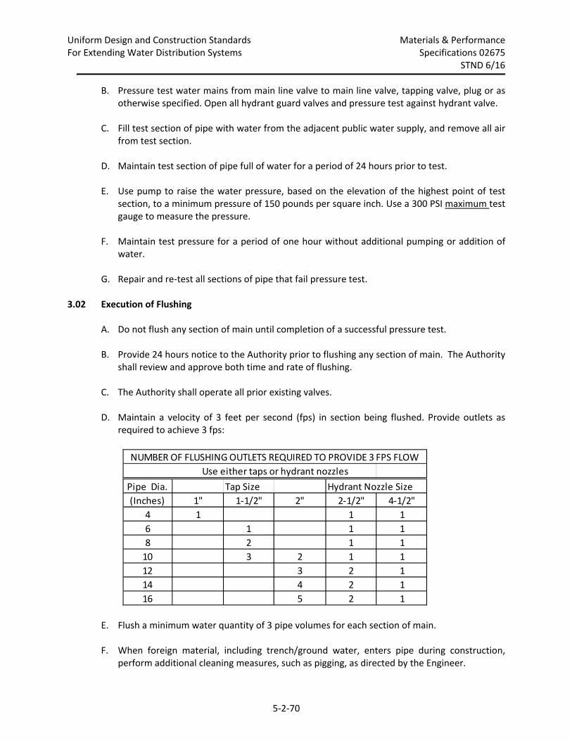
Uniform Design and Construction Standards Materials & Performance For Extending Water Distribution Systems Specifications 02675
STND 6/16
5‐2‐70
B. Pressure test water mains from main line valve to main line valve, tapping valve, plug or as otherwise specified. Open all hydrant guard valves and pressure test against hydrant valve.
C. Fill test section of pipe with water from the adjacent public water supply, and remove all air from test section.
D. Maintain test section of pipe full of water for a period of 24 hours prior to test. E. Use pump to raise the water pressure, based on the elevation of the highest point of test
section, to a minimum pressure of 150 pounds per square inch. Use a 300 PSI maximum test gauge to measure the pressure.
F. Maintain test pressure for a period of one hour without additional pumping or addition of
water. G. Repair and re‐test all sections of pipe that fail pressure test.
3.02 Execution of Flushing A. Do not flush any section of main until completion of a successful pressure test.
B. Provide 24 hours notice to the Authority prior to flushing any section of main. The Authority
shall review and approve both time and rate of flushing. C. The Authority shall operate all prior existing valves. D. Maintain a velocity of 3 feet per second (fps) in section being flushed. Provide outlets as
required to achieve 3 fps:
E. Flush a minimum water quantity of 3 pipe volumes for each section of main.
F. When foreign material, including trench/ground water, enters pipe during construction, perform additional cleaning measures, such as pigging, as directed by the Engineer.
NUMBER OF FLUSHING OUTLETS REQUIRED TO PROVIDE 3 FPS FLOW
Use either taps or hydrant nozzles
Pipe Dia. Tap Size Hydrant Nozzle Size
(Inches) 1" 1‐1/2" 2" 2‐1/2" 4‐1/2"
4 1 1 1
6 1 1 1
8 2 1 1
10 3 2 1 1
12 3 2 1
14 4 2 1
16 5 2 1
Uniform Design and Construction Standards Materials & Performance For Extending Water Distribution Systems Specifications 02675
STND 6/16
5‐2‐71
3.03 Execution of Disinfecting and Health Sampling
A. Do not disinfect a section of pipe until successful completion of pressure testing and
flushing.
B. Disinfect and sample in accordance with AWWA C651, continuous‐feed method using sodium hypochlorite or calcium hypochlorite.
C. Apply chlorine solution by means of a solution feed device (see attached) at the water
supply point for test section. Proportion chlorine solution flow rate to rate of water entering pipe or structure such that resulting free chlorine residual is not less than 50 parts per million (PPM).
D. Retain chlorinated water in pipe or structure at least 24 hours, unless otherwise directed.
Operate all valves and hydrants within disinfection section during retention period except for valves isolating disinfection section from the potable water system.
E. Chlorine residual shall not be less than 25 PPM (mg/L) at any point in pipe or structure at
the end of retention period. Confirm residual by testing. F. After the retention period, thoroughly flush pipe or structure until water in it has a chlorine
residual comparable to that of the water in the adjacent public water supply system. Dispose of chlorinated water from any pipe or structure such that it will not cause damage to any vegetation, fish or animal life and in accordance with any regulatory or permit requirements.
G. Schedule health sampling of the test section(s). As a minimum, take health samples at 1000‐
foot intervals of water main, at the end of each test section, at the end of every branch connection that is longer than 20 feet, and as shown on the Approved Plans. When trench water enters the main during construction, and when Engineer deems warranted, take health samples at 200‐foot intervals after water has stood in the main for a minimum of 16 hours. Obtain health samples in the presence of the Engineer. Flame sampling point prior to sampling. Do not use fire hydrants for sampling points.
1. In Monroe and Genesee counties, schedule health sampling with the county department
of health. Pay all fees associated with sampling/testing. In Ontario and Livingston counties, schedule health sampling with Owner.
2. In Monroe and Genesee counties, take one health sample per sampling location after flushing disinfection water.
3. In Ontario and Livingston counties, take two samples per sampling location. Allow main
to sit for a minimum of 16 hours after flushing disinfection water. Take two sets of samples at each sampling location a minimum of 15 minutes apart while sampling taps
Uniform Design and Construction Standards Materials & Performance For Extending Water Distribution Systems Specifications 02675
STND 6/16
5‐2‐72
are left running. (Sampling Option A as specified in Section 5.1.1.1 of ANSI/AWWA C651 may be used when requested by Contractor and approved in advance by the Authority.)
4. Test samples for coliform, standard heterotrophic plate count and chlorine residual, and
as required by the appropriate health department. H. Re‐flush, re‐chlorinate and re‐sample all sections of pipe that fail health sample tests in
accordance with this section. I. Apply 5% sodium hypochlorite when specified and to any pipe or appurtenance installed
which does not receive 24‐hour disinfection contact time. Apply solution, not more than 60 or less than 30 minutes, before installation using a wide brush or spray applicator.
J. After passing health sample results are achieved, if repairs are made to the main, flush,
disinfect and health sample again in accordance with section 4.11 of ANSI/AWA C651. K. Following successful flushing, pressure testing, and health sampling, abandon all temporary
facilities. Abandon these facilities in accordance with Specification 02680.
~ END OF SECTION~
Uniform Design and Construction Standards Materials & Performance For Extending Water Distribution Systems Specifications 02680
STND 6/16
5‐2‐73
SECTION 02680
WATER SYSTEM ABANDONMENTS PART 1 General
1.01 Section Includes
A. Water Main Abandonments
B. Valve Box Abandonments C. Hydrant Abandonments
1.02 Related Sections A. Section 02655 – Water System Appurtenances
PART 2 Products
2.01 General Material Requirement
A. All materials in contact with potable water shall be NSF‐61 Certified.
2.02 End Caps and Plugs
A. As per Section 02610.
2.03 Straight and End Cap Couplings
A. Refer to Specification 02655.
2.04 End or Line Cap Couplings
A. Smith Blair #481, blind end, with plug.
B. JCM Industries #214, with plug. C. Ford FEC (4” – 12”) or FC4 Steel End Cap Coupling (14” – 24”) with plug.
2.05 Pressure Treated Timbers A. Yellow southern pine.
B. Minimum manufacturer’s guarantee of 30 years against rotting or decay.
Uniform Design and Construction Standards Materials & Performance For Extending Water Distribution Systems Specifications 02680
STND 6/16
5‐2‐74
2.06 Nipples A. As per Specification 02610.
2.07 Plugs for Corporation Taps
A. CC Threads
B. Fabricated from no‐lead brass (UNS Copper Alloy C89520 and C89833) in accordance with
chemical and mechanical requirements of ASTM B584 and AWWA C‐800.
2.08 Concrete A. As per Specification 02700.
2.09 Plywood
A. Minimum Thickness: 3/4 inch.
PART 3 Execution
3.01 Preparation A. Coordinate abandonment of existing water system facilities with the Engineer.
B. Abandon existing water mains on each street after new water main and its hydrants are
placed in service and all services on main to be abandoned have been transferred or replaced.
C. Coordinate with the Authority’s Operations Department for shut down of existing water
mains for each water main abandonment location. D. Have all labor, equipment, and material on site for all water main abandonment
possibilities.
3.02 Water Main Abandonments A. Excavate at water main and locate connection to water main to be abandoned or point of
abandonment.
B. For a corporation abandonment, remove corporation or multiple corporations from water main which is to remain in service including any tapping saddles. Thread openings if necessary and install brass plugs in water main.
Uniform Design and Construction Standards Materials & Performance For Extending Water Distribution Systems Specifications 02680
STND 6/16
5‐2‐75
C. For an abandonment of a tee connection, remove tee, tapping sleeve and valve or other connecting fitting with 3 separate pipe cuts. Cut out a minimum of 3 feet of pipe in water main which is to remain in service. Extend cuts, if necessary, along water main to remain in service so that no existing pipe joint will be within 2 feet of a coupling. Remove a maximum of 19.5’ of pipe. Install a nipple and 2 straight couplings. Plug end of abandoned water main.
D. For an in line abandonment, cut out a maximum of 3 feet of pipe at point of abandonment.
Install an end cap coupling on water main to remain in service and plug water main to be abandoned. Place an adequately sized section of plywood (minimum 3/4” thick) or steel plate against water main to be abandoned in order to contain the concrete thrust block from remainder of trench along abandoned water main. Place an adequately sized, pressure‐treated timber tightly between ends of the water mains. Install concrete thrust block around timber to dimensions which meet the required undisturbed soil bearing area as set forth in the Typical Thrust Block Detail.
E. Engineer shall determine type of abandonment to be performed and its exact location for
each water main abandonment. F. Swab disinfect pipe openings, all fittings, and appurtenances used that will be in contact
with water supply after abandonment is completed as specified in Specification 02675, Article 3.03 I.
G. After completion of each abandonment and before backfilling, place water main back in service. Repair any leaks.
H. Backfill abandonment excavation and restore disturbed area.
3.03 Valve Box Abandonments A. Abandon all valves in the position directed by the Engineer.
B. Remove entire mainline curb boxes and valve boxes only after water main they operate has
been abandoned. C. Excavate as necessary to remove entire curb box and rod or valve box. Backfill
abandonment excavation and restore disturbed area. 3.04 Hydrant Abandonments
A. Remove hydrants only after water main they are connected to has been abandoned.
Uniform Design and Construction Standards Materials & Performance For Extending Water Distribution Systems Specifications 02680
STND 6/16
5‐2‐76
B. Excavate to bottom of hydrant and remove by disconnecting it at its base. Backfill abandonment excavation and restore disturbed area.
C. Refer to 3.03 for hydrant valve box abandonment requirements.
~ END OF SECTION ~
Uniform Design and Construction Standards Materials & Performance For Extending Water Distribution Systems Specifications 02700
STND 6/16
5‐2‐77
SECTION 02700
CONCRETE THRUST BLOCKS PART 1 General
1.01 Section Includes
A. Concrete Thrust Blocks
1.02 Related Sections
A. Section 02600 – Pipe Installation
B. Section 02610 – Ductile Iron Pipe
1.03 Submittals A. Shop Drawing:
1. Concrete mix design.
2. Rebar.
1.04 References
A. ASTM C31, Method of Making and Curing Concrete Compression and Flexure Test
Specimens in the Field.
PART 2 Products
2.01 Concrete A. Twenty‐eight day strength of 2,500 pounds per square inch.
B. Transit mix from batch plant. C. No fly ash or other pozzolan‐containing materials. D. Steel reinforcement shall have a minimum Grade 60 designation.
2.02 Rebar A. No. 6 Steel reinforcing bars.
Uniform Design and Construction Standards Materials & Performance For Extending Water Distribution Systems Specifications 02700
STND 6/16
5‐2‐78
B. Minimum Grade 60 designation. C. Bend last 3 inches of reinforcing bars 90 degrees with 1/2" radius bends.
2.03 Bond Breaker A. 8 mil polyethylene. Refer to Section 02610.
PART 3 Execution
3.01 Concrete Thrust Blocks A. Install concrete thrust blocks for all tees, tapping sleeves, reducers, plugs, caps, bends and
other locations as shown. Install vertical‐down thrust blocks on fittings which change the vertical alignment of the pipe in the downward direction and on horizontal fittings which are partially rotated in the downward direction. Install horizontal thrust blocks on all fittings with no change in vertical alignment. Install vertical‐up thrust blocks on all fittings which change the vertical alignment of the pipe in the upward direction.
B. Install horizontal and vertical‐up thrust blocks with bearing surface directly against undisturbed soil. Install concrete between fitting and undisturbed soil. Form and install block so that its mass and the area bearing on the pipe and on the ground is as shown on the Approved Plans. When block cannot be installed against undisturbed soil, install Select Fill between bearing surface and undisturbed soil. Compact Select Fill to 90% maximum modified Proctor density. Form and install block so that block height is equal to or less than 1/2 the total depth to the bottom of the block, but not less than the pipe diameter. Form and install block such that width is between 1 and 2 times the height.
C. Install vertical‐down blocks so that a minimum 1/3 of block bears on undisturbed soil below
the fittings. Install concrete between fittings and undisturbed soil. The mass of the block and/or the area bearing on the pipe and on the ground in each instance shall be as shown on the Approved Plans.
D. Form thrust blocks, when possible, so that mechanical joint bolts are not covered nor access
to them restricted. E. Install bond breaker between thrust blocks and fittings. F. Install concrete cradle for tapping sleeves. G. Obtain and prepare test cylinders (4 per concrete batch) in accordance with ASTM C31,
Method of Making and Curing Concrete Compression and Flexure Test Specimens in the Field. Furnish cylinders to the Engineer for testing.
~ END OF SECTION ~

5‐2‐79