
Uniform Design and Construction Standards - Section 1 - … · · 2018-01-31uniform design and...
30
UNIFORM DESIGN AND CONSTRUCTION STANDARDS FOR EXTENDING WATER DISTRIBUTION SYSTEMS SECTION 5 STANDARD DETAILS Revised: September 20, 2017
Transcript of Uniform Design and Construction Standards - Section 1 - … · · 2018-01-31uniform design and...
UNIFORM DESIGN AND CONSTRUCTION STANDARDS FOR EXTENDING WATER
DISTRIBUTION SYSTEMS
SECTION 5
STANDARD DETAILS
Revised: September 20, 2017
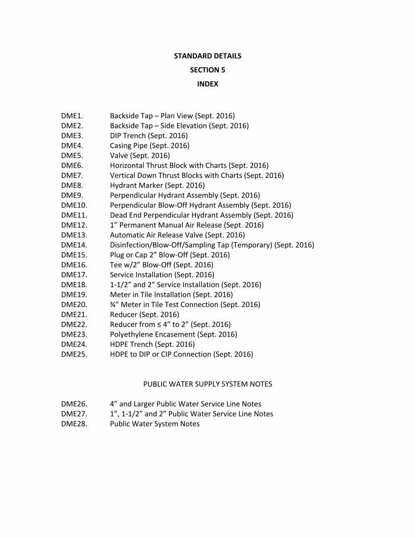
STANDARD DETAILS
SECTION 5
INDEX
DME1. Backside Tap – Plan View (Sept. 2016) DME2. Backside Tap – Side Elevation (Sept. 2016) DME3. DIP Trench (Sept. 2016) DME4. Casing Pipe (Sept. 2016) DME5. Valve (Sept. 2016) DME6. Horizontal Thrust Block with Charts (Sept. 2016) DME7. Vertical Down Thrust Blocks with Charts (Sept. 2016) DME8. Hydrant Marker (Sept. 2016) DME9. Perpendicular Hydrant Assembly (Sept. 2016) DME10. Perpendicular Blow‐Off Hydrant Assembly (Sept. 2016) DME11. Dead End Perpendicular Hydrant Assembly (Sept. 2016) DME12. 1” Permanent Manual Air Release (Sept. 2016) DME13. Automatic Air Release Valve (Sept. 2016) DME14. Disinfection/Blow‐Off/Sampling Tap (Temporary) (Sept. 2016) DME15. Plug or Cap 2” Blow‐Off (Sept. 2016) DME16. Tee w/2” Blow‐Off (Sept. 2016) DME17. Service Installation (Sept. 2016) DME18. 1‐1/2” and 2” Service Installation (Sept. 2016) DME19. Meter in Tile Installation (Sept. 2016) DME20. ¾” Meter in Tile Test Connection (Sept. 2016) DME21. Reducer (Sept. 2016) DME22. Reducer from ≤ 4” to 2” (Sept. 2016) DME23. Polyethylene Encasement (Sept. 2016) DME24. HDPE Trench (Sept. 2016) DME25. HDPE to DIP or CIP Connection (Sept. 2016)
PUBLIC WATER SUPPLY SYSTEM NOTES DME26. 4” and Larger Public Water Service Line Notes DME27. 1”, 1‐1/2” and 2” Public Water Service Line Notes DME28. Public Water System Notes

w ~ 0 / (/) _J
~ 0
w ~ 0
..--0 N / w ~ 0 / (/) _J
~ 0 /
HORIZONTAL THRUST BLOCK SLEEVE & VALVE
3/4" STEEL REINFORCING RODS
ROTATED go· MJ BEND
_[
EXISTING WATER MAIN
~ )
CASING PIPE AS REQUIRED
RJ PIPE-MUST EXTEND 5' BEYOND CASING, BOTH SIDES
UNDISTURBED SOIL
ROTATED go· MJ BEND
HORIZONTAL THRUST BLOCK
3/ 4" STEEL REINFORCING RODS
DOWN THRUST BLOCK
BACKSIDE TAP- PLAN VIEW NOT TO SCALE
SEPT 2016 DATE
DME 1
~ ~----------------------------------._----------------------------~

C)
3: 0 N
w ~ 0 / (/) _J
~ 0
w ~ 0
..--0 N / w ~ 0 / (/) _J
~ 0 /
VERTICAL DOWN THRUST BLOCK
HORIZONTAL THRUST BLOCK
TAPPING SLEEVE & VALVE
ROTATED go· MJ BEND
': .•• :: .:: ..• ·:!.;:···~:·.: . ~: .. :··.· ~·~·~. ~.iilr.~~ . .--.1. f-------1
. .' ·: · .• p ./-: ;, 1111( .•
·.~ :· ::~ -:·~:· · ~./.•. ·: ·~~·~:~:.-.;,1. ·.------1 u,...->...........c.--,w
· ... . . . . ·. ·. , ..
CASING PIPE AS REQUIRED
RJ PIPE-MUST EXTEND 5' BEYOND CASING, BOTH SIDES
ROTATED go· MJ BEND
HORIZONTAL THRUST BLOCK
UNDISTURBED SOIL
BACKSIDE TAP- SIDE ELEVATION NOT TO SCALE
SEPT 2016 DATE
DME 2
~ ~------------------------------------~----------------------~------~

..--0 N / w ~ 0 / (/) _J
~ 0 /
TYPE 4 SELECT FILL (RUN OF BANK SAND) ENVELOPE (WHEN ROCK IS ENCOUNTERED)
6"MIN IN
ROCK
6"MIN IN
ROCK
TRENCH LIMITS
UITABLE NATIVE MATERIAL, COMPACT TO 85% MAX STANDARD PROCTOR DENSITY
ww o._Z -0 O...N
NOTE: EXCAVATION TO MEET OSHA REQUIREMENTS.
DIP TRENCH NOT TO SCALE
SEPT 2016 DATE
DME 3 ~ ~----------------------------------_.----------------------~------~
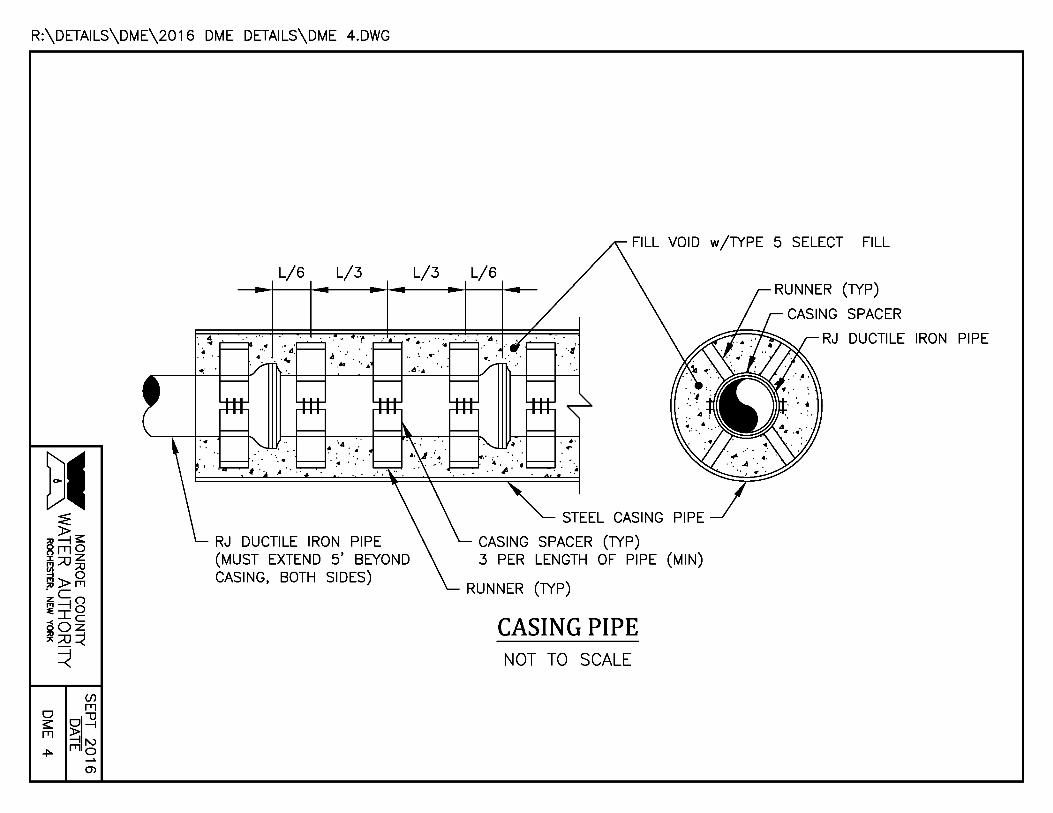
R:\DETAILS\DME\2016 DME DETAILS\DME 4.DWG
L/6 L/3
RJ DUCTILE IRON PIPE (MUST EXTEND 5' BEYOND CASING, BOTH SIDES)
L/3 L/6
STEEL CASING
CASING SPACER (TYP) 3 PER LENGTH OF PIPE (MIN)
RUNNER (TYP)
CASING PIPE NOT TO SCALE
w/TYPE 5 SELECT FILL
RUNNER (TYP)
CASING SPACER
RJ DUCTILE IRON PIPE
C)
3: 0 l[)
w ~ 0 / (/) _J
~ 0
w ~ 0
c:o ,..... 0 N / w ~ 0 / (/) _J
~ 0 / 0:::
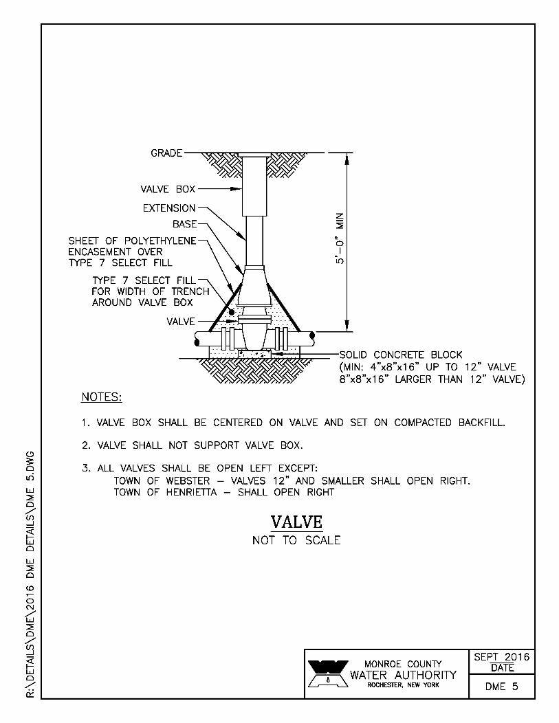
SHEET OF POLYETHYLENE ENCASEMENT OVER TYPE 7 SELECT FILL
TYPE 7 SELECT FILL FOR WIDTH OF TRENCH AROUND VALVE BOX
0 I
l[)
_ __j~;::(~~~~;:;:;::::=--SOLID CONCRETE BLOCK (MIN: 4"x8"x16" UP TO 12" VALVE 8"x8"x16" LARGER THAN 12" VALVE)
NOTES:
1. VALVE BOX SHALL BE CENTERED ON VALVE AND SET ON COMPACTED BACKFILL.
2. VALVE SHALL NOT SUPPORT VALVE BOX.
3. ALL VALVES SHALL BE OPEN LEFT EXCEPT: TOWN OF WEBSTER - VALVES 12" AND SMALLER SHALL OPEN RIGHT. TOWN OF HENRIETIA - SHALL OPEN RIGHT
VALVE NOT TO SCALE
SEPT 2016 DATE
DME 5

R:\DETAILS\DME\2016 DME DETAILS\DME 6.DWG
BEND OR FITIING
PIPE 11 i DEGREE 22~ DEGREE 45 DEGREE 90 DEGREE TEE*, CAP OR
DIAMETER H w A H w A H w A H w A H
(FT) (FT) (FT) (FT) (FT) (FT) (FT) (FT) (FT) (FT) (FT) (FT) (FT)
* SIZE BLOCK BASED ON BRANCH DIAMETER. SOIL BEARING STRENGTH- PSF
PSI TEST PRESSURE
HORIZONTAL AND VERTICAL UP THRUST BLOCKS
BOND BREAKER
CONCRETE THRUST BLOCK
UNDISTURBED SOIL
CONCRETE THRUST BLOCK
UNDISTURBED SOIL H
PLUG w
(FT)
BEND PROFILE BEND ELEVATION
TEE PLAN
BEND PLAN
VERTICAL UP THRUST BLOCKS NOT TO SCALE
CONCRETE THRUST BLOCK
CONCRETE THRUST BLOC
UNDISTURBED SOIL UNDISTURBED SOIL
A
TEE ELEVATION
NCRETE THRUST BLOCK
CONCRETE THRUST BLOC
UNDISTURBED SOIL
BEND ELEVATION
HORIZONTAL THRUST BLOCKS NOT TO SCALE
I
A (FT)
I
<(
SEPT 2016 DATE
DME 6

R:\DETAILS\DME\2016 DME DETAILS\DME 7.DWG
PIPE DIAMETER L
(FT)
BEND
11i DEGREE 22~ DEGREE 45 DEGREE 90 DEGREE
w (FT)
:r:
H VOL L w H VOL L w H VOL L w H (FT) (CY) (FT) (FT) (FT) (CY) (FT) (FT) (FT) (CY) (FT) (FT) (FT)
SOIL BEARING STRENGTH- PSF PSI TEST PRESSURE
VERTICAL DOWN THRUST BLOCKS
BOND BREAKER
CONCRETE THRUST BLOCK
UNDISTURBED SOIL
NOTES:
BEND ELEVATION
L
BEND PLAN
BOND BREAKER
REBAR (TYP)
1. THRUST BLOCKS SHALL BE CENTERED HORIZONTALLY ON BENDS. 2. VOLUMES SHOWN IN CHART ARE MINIMUMS.
VERTICAL DOWN THRUST BLOCKS NOT TO SCALE
VOL (CY)
SEPT 2016 DATE
DME 7

" 3: 0 OCl
w ~ 0 / (/) _J
~ w 0
w ~ 0
(!)
0 N / w ~ 0 / (/) _J
~ 0 /
12" DIAMETER x 1/8" THICK (SOLID) RED OR ORANGE PLASTIC DISK TO READ: "NOT IN SERVICE"
ALL LETIERING SHALL BE 2" MINIMUM AND PAINTED BLACK BY USE OF A STENCIL.
HYDRANT MARKER TO BE INSTALLED AND MAINTAINED ON STEAMER NOZZLE OF EACH HYDRANT UNTIL HYDRANT IS PLACED IN SERVICE.
HYDRANT MARKER NOT TO SCALE
.. MONROE COUNlY ~ WATER AUTHORITY ~ ROCHESTER, NEW YORK
SEPT 2016 DATE
DME 8 ~ ~----------------------------------._--------------------~------~

R:\DETAILS\DME\2016 DME DETAILS\DME 9.DWG
5.5' BURY HYDRANT TO BE ----1-a1
INSTALLED w/4-1/2" NOZZLE FACING THE ROADWAY
VALVE BOX-~
CONCRETE THRUST BLOCK LENGTH ALONG MAIN IS 2' (MIN)
MJ ANCHOR TEE, 6" OUTLET
SOLID CONCRETE (MIN:4"x8"x16")
SHEET OF POLYETHYLENE ENCASEMENT OVER TYPE 7 SELECT FILL
--~~~-TYPE 7 SELECT FILL FOR WIDTH OF HYDRANT TRENCH
~~~~~--SOLID CONCRETE BLOCK (MIN:8"x8"x16")
6"x18" (MIN) ANCHOR PIPE - ONE CONTINUOUS LENGTH FROM VALVE TO HYDRANT
MJ GATE VALVE
PERPENDICULAR HYDRANT ASSEMBLY NOT TO SCALE

R:\DETAILS\DME\2016 DME DETAILS\DME 1 O.DWG
CONCRETE THRUST BLOCK LENGTH ALONG MAIN IS 2' (MIN)
6"x45" MJ
6" FOSTER ADAPTOR
6.5' BURY HYDRANT TO BE ----..-111
INSTALLED w/4-1/2" NOZZLE FACING THE ROADWAY
VALVE BOX -----1
SOLID CONCRETE (MIN:4"x8"x16")
SHEET OF POLYETHYLENE ENCASEMENT OVER TYPE 7 SELECT FILL
TYPE 7 SELECT FILL FOR WIDTH OF HYDRANT TRENCH
~.,.:.,..:.,..:.~~~-SOLID CONCRETE BLOCK (MIN:8"x8"X16")
6"x18" (MIN) ANCHOR PIPE - ONE CONTINUOUS LENGTH FROM VALVE TO HYDRANT
6" MJ GATE VALVE
PERPENDICULAR BLOW-OFF HYDRANT ASSEMBLY NOT TO SCALE
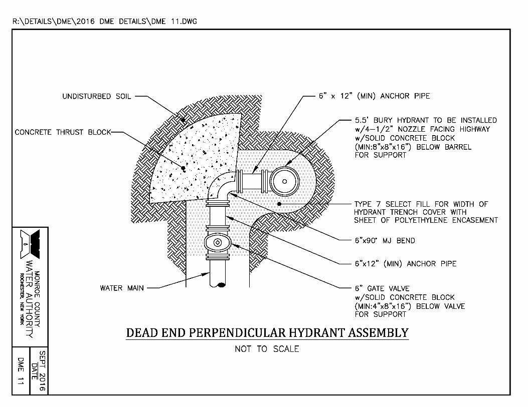
R:\DETAILS\DME\2016 DME DETAILS\DME 11.DWG
UNDISTURBED SOIL
CONCRETE THRUST BLOCK
12" (MIN) ANCHOR PIPE
5.5' BURY HYDRANT TO BE INSTALLED w/4-1/2" NOZZLE FACING HIGHWAY w/SOLID CONCRETE BLOCK (MIN:8"x8"x16") BELOW BARREL FOR SUPPORT
e---~~~--lYPE 7 SELECT FILL FOR WIDTH OF HYDRANT TRENCH COVER WITH SHEET OF POLYETHYLENE ENCASEMENT
6"x90" MJ BEND
6"x12" (MIN) ANCHOR PIPE
6" GATE VALVE w/SOLID CONCRETE BLOCK (MIN:4"x8"x16") BELOW VALVE FOR SUPPORT
DEAD END PERPENDICULAR HYDRANT ASSEMBLY NOT TO SCALE
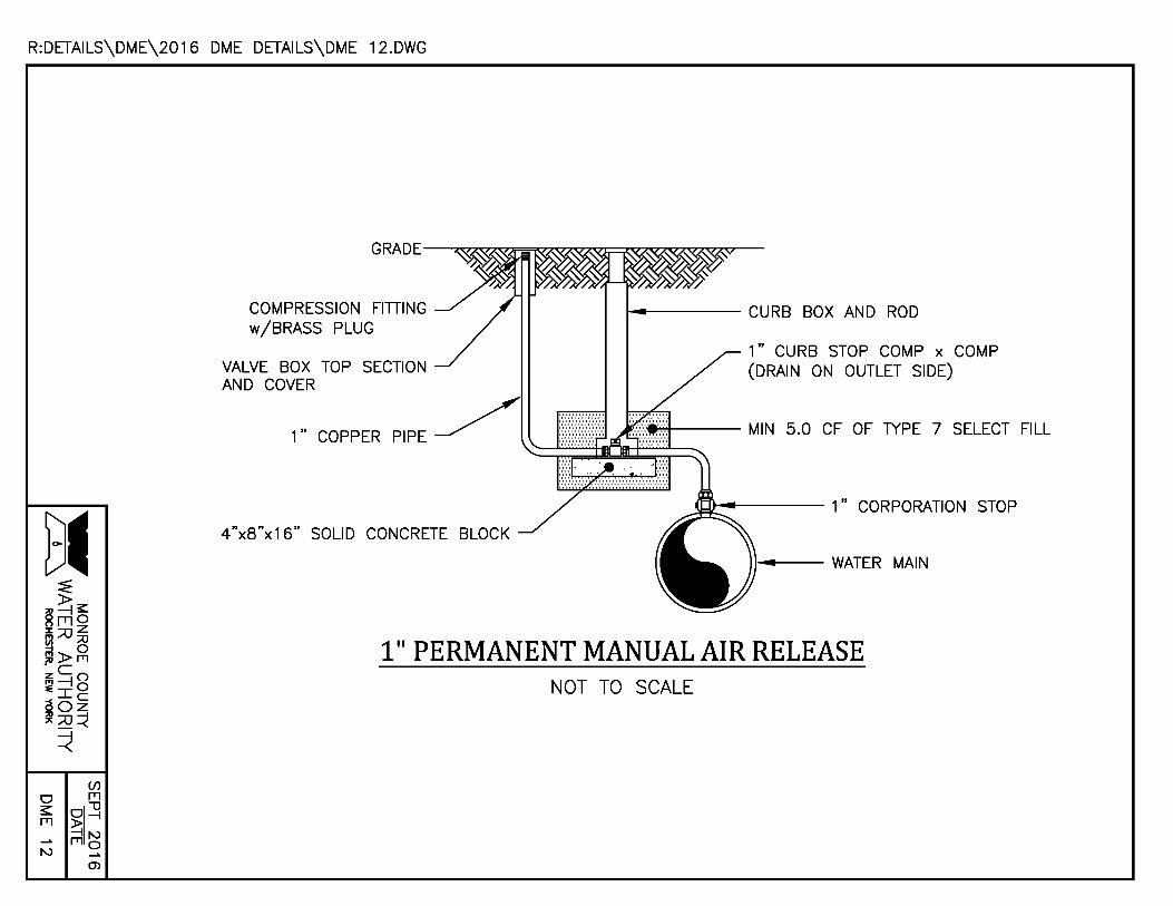
R:DETAILS\DME\2016 DME DETAILS\DME 12.DWG
COMPRESSION FITIING w/BRASS PLUG
VALVE BOX TOP SECTION AND COVER
1" COPPER PIPE
4"x8"x16" SOLID CONCRETE BLOCK
~---- CURB BOX AND ROD
1" CURB STOP COMP x COMP (DRAIN ON OUTLET SIDE)
~-- WATER MAIN
1" PERMANENT MANUAL AIR RELEASE NOT TO SCALE

w :::i!: 0 / (/) _J
~ w 0
w :::i!: 0
lO
0 N / w :::i!: 0 / (/) _J
~ w 0 _,;,
1 /2" FULL BED HYDRATED NON-SHRINK CEMENT MORTAR
PRECAST CONCRETE GRADE RING
5' SQUARE VAULT
2" VENT (GALVANIZED PI w/MECHANICALLY ATIACHED INSECT SCREEN
lO I
I")
1" THREADED BRASS NIPPLE, LENGTH TO BE DETERMINED IN THE FIELD
1" AWWA CC TAPPER x 1" FIPT CORPORATIO
0 I
I")
NEENAH R-1741-D SET OVER MATCHING ROOF OPENING AND INSTALLED FLUSH WITH GRADE
COAT ALL COMPONENTS w/1 /2" PREHYDRATED NON-SHRINK CEMENT MORTAR
!.-!---BOLLARD - 4" NOMINAL DIAMETER STEEL PIPE FILLED w/CONCRETE, PAINTED SAFETY YELLOW (TYP) WITH STEEL ACORN CAP
ER-UP SAFETY POST
~,....-----4,000 PSI CONCRETE (TYP)
ALUMINUM LADDER RUNGS CAST INTO WALL IN ACCORDANCE WITH OSHA REQUIREMENTS
" AUTOMATIC AIR RELEASE VALVE
TYPE 2 SELECT FILL
PLACE PIPE CUT -OUTS TO LEAVE A 3" GAP AROUND THE WATER MAIN
AUTOMATIC AIR RELEASE VALVE NOT TO SCALE
SEPT 2016
~ WA~~~RO~U~~~~ITY DATE ~ ROCHESTER, NEW YORK DM E 1 3
~ L-----------------------------------------------------------------------------------------------------------~------------------~----------~

w :::;;; 0 / (/) _J
~ 0
w :::;;; 0
co .-0 N / w :::;;; 0 / (/) _J
~ 0 /
1" CURB STOP 12" 1" COPPER
~----- 1" COPPER OR PLASTIC (MIN)
~---- CORPORATION STOP
~--- WATER MAIN
NOTE: IN THE PRESENCE OF A WATER AUTHORilY REPRESENTATIVE REMOVE ALL CORPORATIONS ASSOCIATED WITH TEMPORARY DISINFECTION/SAMPLE TAPS AND REPLACE WITH THREADED BRASS PLUGS.
DISINFECTION/BLOW-OFF /SAMPLING TAP (TEMPORARY) NOT TO SCALE
SEPT 2016 DATE
DME 14 ~ ~------------------------------_.--------------------~----~

w ~ 0 / (/)
WATER MAIN -----+---1
CONCRETE THRUST ~~~.p.-:....-a BLOCK
SHEET OF POLYETHYLENE ENCASEMENT OVER TYPE 7 SELECT FILL
PLAN
MJ PLUG OR CAP WITH 2" IPT TAP (DI) OR FLANGED PIPE w/BLIND FLANGE AND 2" IPT TAP (STEEL)
UNDISTURBED SOIL
TYPE 7 SELECT FILL
CURB BOX AND ROD
BOX w/TOP
2" BRASS NIPPLE
2" BRASS NIPPLE _J 2"x90" BRASS
~ 2" CURB STOP w/DRAIN
CONCRETE BLOCK (MIN:4"x8"x16")
0
w ~ 0
..--0 N / w ~ 0 / (/) _J
~ 0 /
2" BRASS
ELEVATION
PLUG OR CAP 2" BLOW-OFF NOT TO SCALE
SEPT 2016 DATE
DME 15
~ ~--------------------------------~--------------------~------~
w ~ 0 / (/) _J
~ 0
w ~ 0
c:o ..--0 N / w ~ 0 / (/) _J
~ 0 /
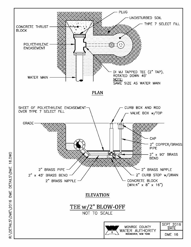
CONCRETE THRUST -~~t=-:-=-:T~-:e BLOCK
POLYETHYLENE -____,l9~~~ ENCASEMENT
WATER MAIN ----It--~
SHEET OF POLYETHYLENE ENCASEMENT OVER TYPE 7 SELECT FILL
PLAN
UNDISTURBED SOIL
TYPE 7 SELECT FILL
Dl MJ TAPPED TEE (2" TAP), ROTATED DOWN 45" NOTE: SAME SIZE AS WATER MAIN
CURB BOX AND ROD
VALVE BOX w/TOP
CAP
2" COPPER/BRASS PIPE
~==:::;:===;!m!=:!IDW:;!h'!'lf:-'-:-~~~- 2" x 90" BRASS
2" BRASS PIPE
2" x 45" BRASS BEND
2" BRASS NIPPLE
ELEVATION
TEE w/2" BLOW-OFF NOT TO SCALE
BEND
BRASS NIPPLE
2" CURB STOP w/DRAIN
CONCRETE BLOCK (MIN:4" X 8" X 16")
SEPT 2016 DATE
DME 16
~ ~--------------------------------~--------------------~------~

R:\DETAILS\DME\2016 DME DETAILS\DME 17.DWG
RIGHT-OF-WAY OR WATER MAIN EASEMENT LINE~ DRILL 3/16" HOLE 4-1/2" FROM TOP OF VALVE BOX AND INSERT TRACING WIRE AND KNOT
0::: w ~-- TRACING WIRE TO BE WRAPPED
SERVICE 6 AROUND OUTSIDE OF CURB BOX u
BARE TRACING WIRE TO WRAPPED AROUND AND
z ~
0::: w > 0 u z ~
H4--- CURB BOX w/ROD TAPED TO CORPORATION STOP
CORPORATION STOP (INSTALL WITH OPERATING KEY POSITIONED ON SIDE)
NOTES:
L{)
COATED TRACING WIRE
SOLID CONCRETE (MIN:4"x8"x16")
L{) STOP
BARE TRACING WIRE TO BE ATIACHED AND TAPED TO COUPLING OR TO CONSUMER TRACING WIRE
BARE TRACING WIRE TO BE WRAPPED AROUND AND TAPED TO CURB BOX
1. COPPER SERVICE TO BE USED UNLESS OTHERWISE APPROVED BY THE ENGINEER.
2. TRACING WIRE TO BE USED WITH POLYETHYLENE SERVICE ONLY.
SERVICE INSTALLATION NOT TO SCALE
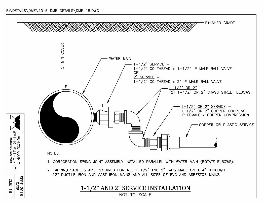
R:\DETAILS\DME\2016 DME DETAILS\DME 18.DWG
NOTES:
0::: w > 0 (.)
z ~
L()
1-1/2" SERVICE -1-1/2" CC THREAD x 1-1/2" IP MALE BALL VALVE OR 2" SERVICE -1-1 /2" CC THREAD x 2" IP MALE BALL VALVE
1 -1/2" OR 2" -(2) 1-1 /2" OR 2" BRASS STREET ELBOWS
1-1/2" OR 2" SERVICE -1-1/2" OR 2" COPPER COUPLING, IP FEMALE x COPPER COMPRESSION
COPPER OR PLASTIC SERVICE
1. CORPORATION SWING JOINT ASSEMBLY INSTALLED PARALLEL WITH WATER MAIN (ROTATE ELBOWS).
2. TAPPING SADDLES ARE REQUIRED FOR ALL 1-1 /2" AND 2" TAPS MADE ON A 4" THROUGH 12" DUCTILE IRON AND CAST IRON MAINS AND ALL SIZES OF PVC AND ASBESTOS MAINS
1-1/2" AND 2" SERVICE INSTALLATION NOT TO SCALE
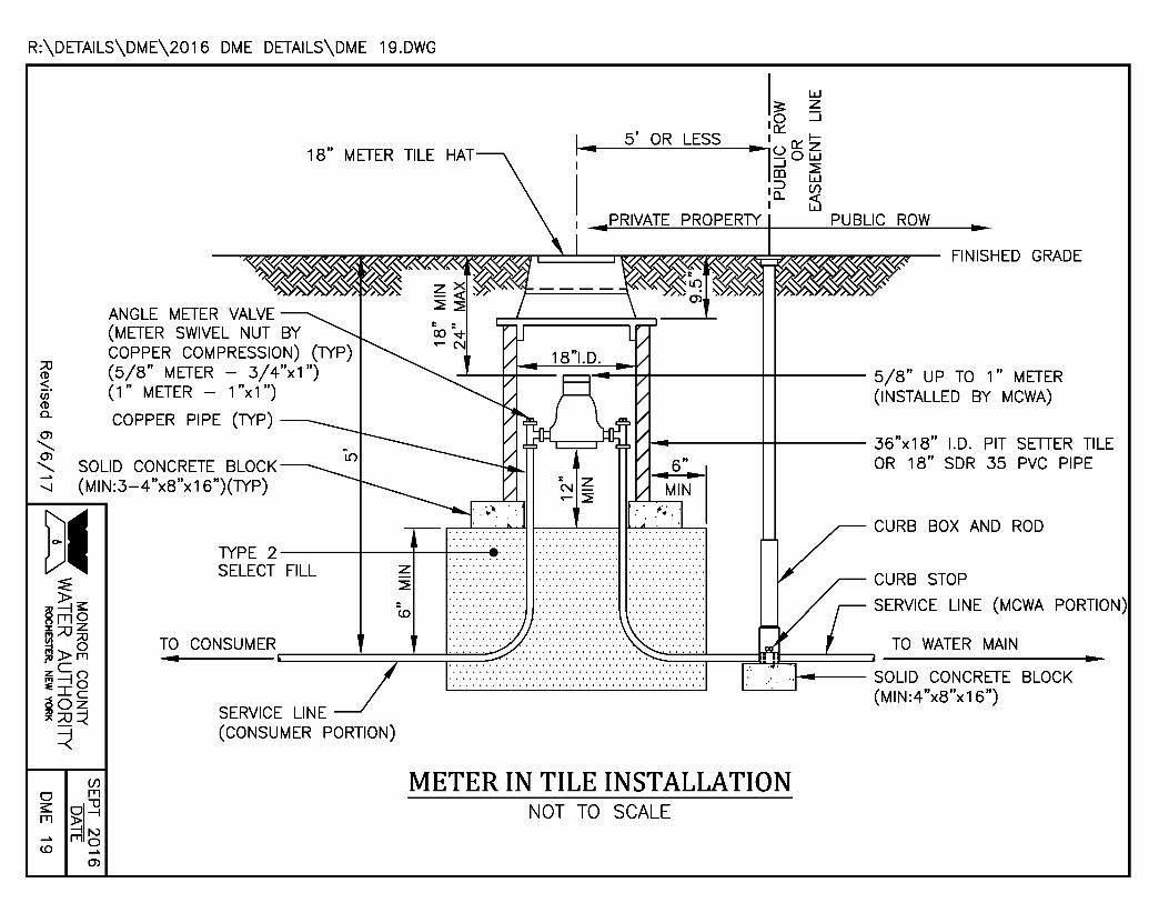
R:\DETAILS\DME\2016 DME DETAILS\DME 19.DWG
;a CD ~. CJJ CD c...
Ol ..........
I~ ~ I~ _.1
5 I OR LESS I 0::: 1--•lo o ~ _J ~ (D w
I::::> (f) 0.... <(
I W
1-18" METER TILE HAT
PRIVATE PROPERTY PUBLIC ROW
ANGLE METER VALVE (METER SWIVEL NUT BY COPPER COMPRESSION) (TYP) (5/8" METER - 3/4"x1 ") (1" METER - 1"x1")
---'-----++--- .--~-t-71------+-+---- 5/8" UP TO 1 II METER (INSTALLED BY MCWA)
COPPER PIPE (TYP) --~-----++----- 36"x18" I.D. PIT SETTER TILE
Ol "'-. SOLID CONCRETE BLOCK 6" OR 18" SDR 35 PVC PIPE
--.J (MIN:3-4"x8"x16")(TYP) : z N..-~
..................................... TYPE 2 ----+---+----+-.. -.. -.. --. ::::. ::::::::::::. :::::::::::. SELECT FILL z
~
CD
CURB BOX AND ROD
CURB STOP
SERVICE LINE (MCWA PORTION)
TO WATER MAIN
~--SOLID CONCRETE BLOCK '-----"'-------' (MIN:4"x8"x16")
SERVICE LINE (CONSUMER PORTION)
METER IN TILE INSTALLATION NOT TO SCALE

ANGLE METER COUPLING (FORD L34-23) (lYP)
SOLID CONCRETE BLOCK ~ (MIN:4"x8"x16") (lYP) 0 0 N
w ~ 0 / (/) _J
0 I
3/ 4" CURB STOP AND BOX (lYP)
PLAN
FORD PMBC-3 METER BOX COVER (FOR PVC PIPE, LID SITS ON PLAIN END OF PIPE)
,--~~~~~====~~~~~.-GRADE
~---18" PVC DR 35 PIPE OR 6" HDPE N-12 CORRUGATED PIPE
3/ 4" BRASS PIPE (lYP)
3/ 4" COPPER PIPE (lYP)
~ ~~~~tc~~~E B~~~p~~~~~~G _ _,--:·::::::::::::::::::::::::::::::::::::::::::::::::::::::::::~ ::~::•::::+----lYPE 2 SELECT FILL
w x F.I.P. THREAD (lYP) PROFILE ~
0
,..... 0 N / w ~ 0 / (/) _J
~ 0 /
3/4" METER-IN-TILE TEST CONNECTION NOT TO SCALE
SEPT 2016 DATE
DME 20
~ ~----------------------------------._----------------------------~

R:\DETAILS\DME\2016 DME DETAILS\DME 21.DWG
CONCRETE THRUST BLOCK NDISTURBED SOIL
(/)
0 fTl
~ §;I~ ~I\.)
1\.) fTl 0 __. ())
REDUCER
TRENCH LIMIT
SECTION
MINIMUM REQUIRED BEARING AREA (SQ FT)
REDUCER NOT TO SCALE
BEARING FACE
MINIMUM 2-)2'
PLAN
~ = BEARING AREA OF THRUST BLOCK ~ OUTSIDE TRENCH LIMITS IN
UNDISTURBED SOIL
<.-' s: 0 N N
w ~ 0 / (/) _J
~ w 0
w ~ 0
(()
0 N / w ~ 0 / (/) _J
~ w 0 <":
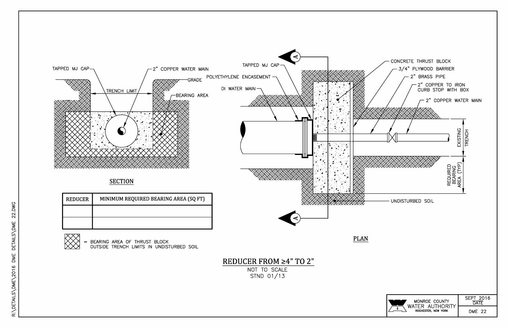
TAPPED MJ CAP
REDUCER
2" COPPER WATER MAIN TAPPED MJ CAP
~7'r77....,...,....77""""-c RADE POLYETHYLENE ENCASEMENT
SECTION
MINIMUM REQUIRED BEARING AREA (SQ FT)
BEARING AREA OF THRUST BLOCK OUTSIDE TRENCH LIMITS IN UNDISTURBED SOIL
Dl WATER MAIN
REDUCER FROM ~4" TO 2" NOT TO SCALE
STND 01/13
PLAN
CONCRETE THRUST BLOCK
3/4" PLYWOOD BARRIER
2" BRASS PIPE
2" COPPER TO IRON CURB STOP WITH BOX
2" COPPER WATER MAIN
~ MONROE COUNlY ~ WATER AUTHORITY ~ ROCHESTER, NEW YORK
<.-' I z I- u (/) ~ X ~ w I-
SEPT 2016 DATE
DME 22
~ ~------------------------------------------------------------------------------------------------------------~~------------------------------~

R:\DETAILS\DME\2016 DME DETAILS\DME 23.DWG
DUCTILE IRON PIPE POLYETHYLENE ENCASEMENT
POLYETHYLENE ENCASEMENT NOT TO SCALE
STND 02/15
LYETHYLENE ENCASEMENT
DUCTILE IRON PIPE

C)
3: 0 -.:IN
w ~ 0 / (/) _J
~ w 0
w ~ 0
(0
0 N / w ~ 0 / (/) _J
~ w 0 ~
TYPE 4 SELECT FILL,----~~~•··:• COMPACT TO 85% MAX STANDARD PROCTOR DENSITY IN NON-PAVEMENT AREAS AND 95% MAX MODIFIED PROCTOR DENSITY IN PAVEMENT AREAS
HOPE TRENCH NOT TO SCALE
UITABLE NATIVE MATERIAL
ww a_Z -0 a...N
SEPT 2016 DATE
DME 24
(/) ~----------------------------------_.----------------------~------~
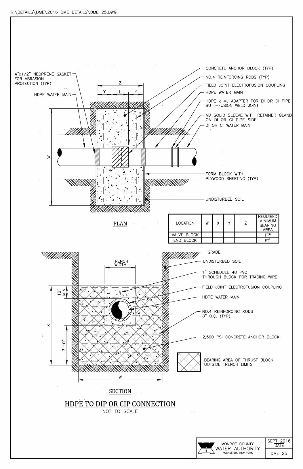
R:\DETAILS\DME\2016 DME DETAILS\DME 25.DWG
4"x1 /2" NEOPRENE GASKET FOR ABRASION PROTECTION (TYP)
HOPE WATER
X
0 I
I")
PLAN
TRENCH WIDTH
w
SECTION
LOCATION
VALVE BLOCK END BLOCK
HDPE TO DIP OR CIP CONNECTION NOT TO SCALE
CONCRETE ANCHOR BLOCK (TYP)
N0.4 REINFORCING RODS (TYP)
FIELD JOINT ELECTROFUSION COUPLING
HOPE WATER MAIN
HOPE x MJ ADAPTER FOR Dl OR Cl PIPE BUTI -FUSION WELD JOINT
MJ SOLID SLEEVE WITH RETAINER GLAND ON Dl OR Cl PIPE SIDE Dl OR Cl WATER MAIN
REQUIRED
w X y z MINIMUM BEARING
AREA FT2 FT2
RADE
UNDISTURBED SOIL
1" SCHEDULE 40 PVC THROUGH BLOCK FOR TRACING WIRE
FIELD JOINT ELECTROFUSION COUPLING
HOPE WATER MAIN
N0.4 REINFORCING RODS 8" O.C. (TYP)
2,500 PSI CONCRETE ANCHOR BLOCK
BEARING AREA OF THRUST BLOCK OUTSIDE TRENCH LIMITS
SEPT 2016 DATE
DME 25
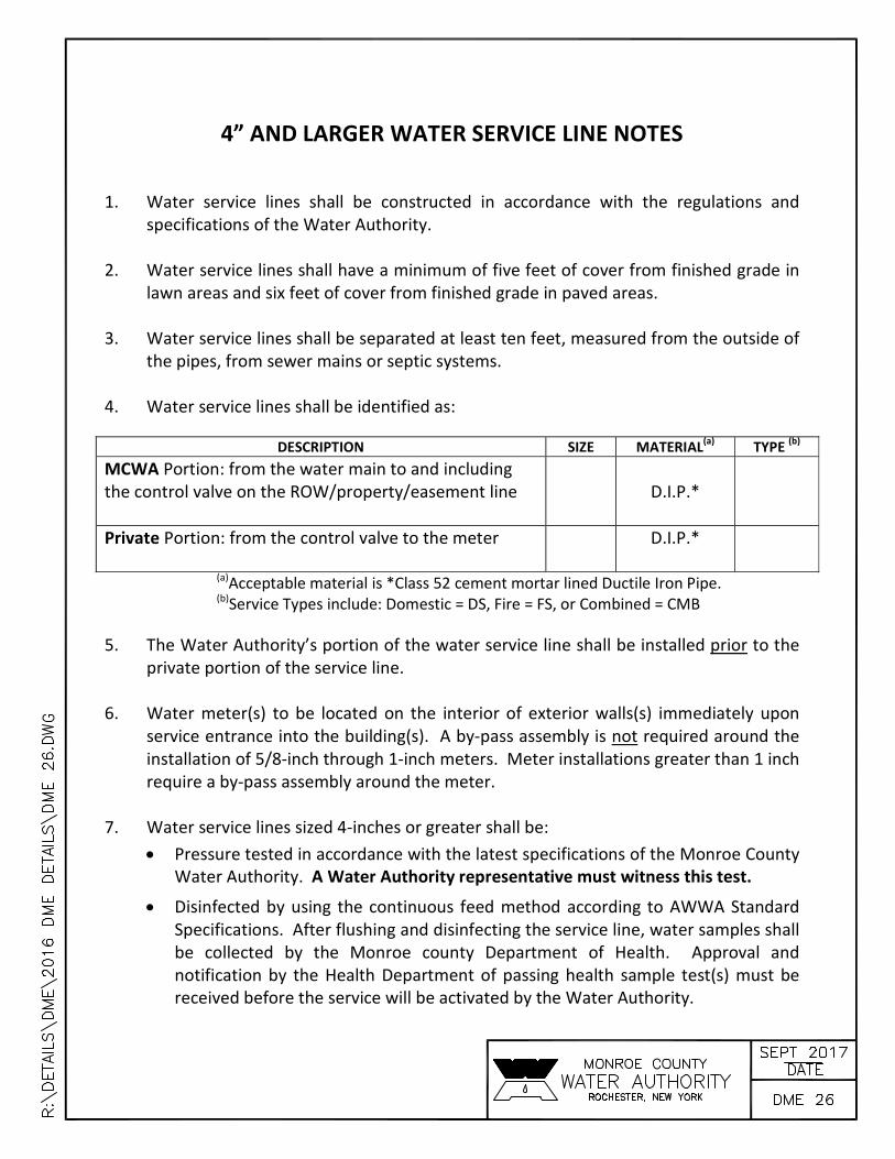
4” AND LARGER WATER SERVICE LINE NOTES
1. Water service lines shall be constructed in accordance with the regulations and specifications of the Water Authority.
2. Water service lines shall have a minimum of five feet of cover from finished grade in
lawn areas and six feet of cover from finished grade in paved areas. 3. Water service lines shall be separated at least ten feet, measured from the outside of
the pipes, from sewer mains or septic systems. 4. Water service lines shall be identified as:
DESCRIPTION SIZE MATERIAL(a) TYPE
(b)
MCWA Portion: from the water main to and including the control valve on the ROW/property/easement line
D.I.P.*
Private Portion: from the control valve to the meter
D.I.P.*
(a)Acceptable material is *Class 52 cement mortar lined Ductile Iron Pipe. (b)Service Types include: Domestic = DS, Fire = FS, or Combined = CMB
5. The Water Authority’s portion of the water service line shall be installed prior to the private portion of the service line.
6. Water meter(s) to be located on the interior of exterior walls(s) immediately upon
service entrance into the building(s). A by‐pass assembly is not required around the installation of 5/8‐inch through 1‐inch meters. Meter installations greater than 1 inch require a by‐pass assembly around the meter.
7. Water service lines sized 4‐inches or greater shall be:
Pressure tested in accordance with the latest specifications of the Monroe County Water Authority. A Water Authority representative must witness this test.
Disinfected by using the continuous feed method according to AWWA Standard Specifications. After flushing and disinfecting the service line, water samples shall be collected by the Monroe county Department of Health. Approval and notification by the Health Department of passing health sample test(s) must be received before the service will be activated by the Water Authority.

1”, 1-1/2” AND 2” WATER SERVICE LINE NOTES 1. Water service lines shall be constructed in accordance with the regulations and
specifications of the Water Authority. 2. Water service lines shall have a minimum of five feet of cover from finished
grade in lawn areas and six feet of cover from finished grade in paved areas. 3. Water service lines shall be separated at least ten feet, measured from the outside
of the pipes, from sewer mains or septic systems. 4. Water service lines shall be identified as:
DESCRIPTION SIZE (a) MATERIAL(b) TYPE (c)
MCWA Portion = from the water main to and including the control valve on the ROW/property/easement line
Type “K” Copper
Private Portion = from the control valve to the meter
(a) Minimum size is 1-inch. (b) Acceptable material for private portion is either Type “K” Copper or
Polyethylene plastic (PE) #4710, SDR 9, ASTM 2737, NSF-PW, 250 psi (CTS OD)
(c) Service Types include: Domestic = DS, Fire = FS, or Combined = CMB
5. The Water Authority’s portion of the service line shall be installed after the private portion of service is installed.
6. Water meter(s) to be located on the interior of exterior wall(s) immediately upon
service entrance into the building(s), or in a meter tile when conditions warrant. A by-pass assembly is not required around the installation of 5/8-inch through 1-inch meters. Meter installations greater than 1-inch may require a by-pass assembly around the meter.

PUBLIC WATER SYSTEM NOTES Water mains and appurtenances to be constructed in accordance with the regulations andspecifications of the Water Authority:
Material: Water main(s) shall be _____-inch ductile iron cement-lined Class 52.
Water service(s) shall be _____-inch Type K Copper from the water main to the curb boxand _____-inch (Type K soft Copper or PE #4710) from the curb box to the meter.
Water meter(s) shall be located on the interior of exterior walls immediately upon serviceentrance into the building(s). On metered services requiring a 1 1/2-inch or larger meter abypass around the meter is required.
All gate valves shall have stainless steel body and bonnet bolts.
Tests:
Soil Test. The contractor shall provide a soil test evaluation to determine the need forpolyethylene encasement per ANSI/AWWS C105/AZ1.5-82 prior to water main installation.Soil testing shall be conducted by an approved soil testing laboratory in accordance withWater Authority standards.
Pressure Test. Water mains to be pressure tested in accordance with the latest WaterAuthority specifications. A Water Authority representative must witness this test.
Health Sample. The water main shall be disinfected equal to AWWA StandardSpecifications, designation C-651, by using the continuous feed method. After flushing anddisinfecting the water main, water samples shall be collected from the main by the MonroeCounty Health Department. Fire hydrants are not acceptable sampling points. Approval andnotification by the Health Department must be received before the main is placed in service.
Installation:
Water mains and all water service lines shall have a minimum of five feet of cover fromfinished grade in lawn areas and a minimum of six feet of cover from finished grade in pavedareas.
Minimum vertical separation between water main and sewer mains shall be 18” measuredfrom the outside of the pipes at the point of crossing. Minimum horizontal separationbetween water mains and sewer mains shall be ten feet measured from the outside of thepipes. One full length of water main shall be centered under or over the sewer so that bothjoints will be as far from the sewer as possible. Where a water main crosses under a sewer,adequate structural support (compacted selected fill) shall be provided for the sewers toprevent excessive deflection of joints and settling on and breaking the water mains.
Fire hydrant weep holes (drains) shall be plugged when ground water is encountered withinseven feet of the finished grade.
All mechanical joint fittings (tees, bends, plugs, etc.) shall be backed with 2500 psi concretethrust blocks of appropriate size to provide thrust restraint.


