Uniflair LE DX Technical Specifications · 2 Uniflair LE DX Technical Specifications 990-4483N-001...
74
Technical Specifications Uniflair™ LE DX 208/230/460/575V, 3 Ph, 60 Hz, 15 – 100 kW 5 – 30 ton
Transcript of Uniflair LE DX Technical Specifications · 2 Uniflair LE DX Technical Specifications 990-4483N-001...

Technical Specifications
Uniflair™ LE DX
208/230/460/575V, 3 Ph, 60 Hz, 15 – 100 kW5 – 30 ton

Schneider Electric IT Corporation Legal DisclaimerThe information presented in this manual is not warranted by the Schneider Electric IT Corporation to be authoritative, error free, or complete. This publication is not meant to be a substitute for a detailed operational and site specific development plan. Therefore, Schneider Electric IT Corporation assumes no liability for damages, violations of codes, improper installation, system failures, or any other problems that could arise based on the use of this Publication.
The information contained in this Publication is provided as is and has been prepared solely for the purpose of evaluating data center design and construction. This Publication has been compiled in good faith by Schneider Electric IT Corporation. However, no representation is made or warranty given, either express or implied, as to the completeness or accuracy of the information this Publication contains.
IN NO EVENT SHALL SCHNEIDER ELECTRIC IT CORPORATION, OR ANY PARENT, AFFILIATE OR SUBSIDIARY COMPANY OF SCHNEIDER ELECTRIC IT CORPORATION OR THEIR RESPECTIVE OFFICERS, DIRECTORS, OR EMPLOYEES BE LIABLE FOR ANY DIRECT, INDIRECT, CONSEQUENTIAL, PUNITIVE, SPECIAL, OR INCIDENTAL DAMAGES (INCLUDING, WITHOUT LIMITATION, DAMAGES FOR LOSS OF BUSINESS, CONTRACT, REVENUE, DATA, INFORMATION, OR BUSINESS INTERRUPTION) RESULTING FROM, ARISING OUT, OR IN CONNECTION WITH THE USE OF, OR INABILITY TO USE THIS PUBLICATION OR THE CONTENT, EVEN IF SCHNEIDER ELECTRIC IT CORPORATION HAS BEEN EXPRESSLY ADVISED OF THE POSSIBILITY OF SUCH DAMAGES. SCHNEIDER ELECTRIC IT CORPORATION RESERVES THE RIGHT TO MAKE CHANGES OR UPDATES WITH RESPECT TO OR IN THE CONTENT OF THE PUBLICATION OR THE FORMAT THEREOF AT ANY TIME WITHOUT NOTICE.
Copyright, intellectual, and all other proprietary rights in the content (including but not limited to software, audio, video, text, and photographs) rests with Schneider Electric IT Corporation or its licensors. All rights in the content not expressly granted herein are reserved. No rights of any kind are licensed or assigned or shall otherwise pass to persons accessing this information.
This Publication shall not be for resale in whole or in part.

Table of Contents
Technical Data...................................................................1Model Number Nomenclature. . . . . . . . . . . . . . . . . . . . . . . . . . . . . . . . . 1
Overview............................................................................2Standard Features . . . . . . . . . . . . . . . . . . . . . . . . . . . . . . . . . . . . . . . . . 2
Optional Features . . . . . . . . . . . . . . . . . . . . . . . . . . . . . . . . . . . . . . . . . . 3
Airflow Configurations. . . . . . . . . . . . . . . . . . . . . . . . . . . . . . . . . . . . . . . 4Upflow . . . . . . . . . . . . . . . . . . . . . . . . . . . . . . . . . . . . . . . . . . . . 4Downflow . . . . . . . . . . . . . . . . . . . . . . . . . . . . . . . . . . . . . . . . . . 4
Operating Descriptions . . . . . . . . . . . . . . . . . . . . . . . . . . . . . . . . . . . . . . 5Air Cooled Direct Expansion Units . . . . . . . . . . . . . . . . . . . . . . 5Twin-Cool Direct Expansion Units(Air-cooled or Water-cooled) . . . . . . . . . . . . . . . . . . . . . . . . . . . 5Energy-Saving Units . . . . . . . . . . . . . . . . . . . . . . . . . . . . . . . . . 6
Performance Specifications ...............................................7Air-Cooled DX Units (TD/UAV). . . . . . . . . . . . . . . . . . . . . . . . . . . . . . . . 7
Water-Cooled DX Units (TD/UWV). . . . . . . . . . . . . . . . . . . . . . . . . . . . 100% propylene glycol . . . . . . . . . . . . . . . . . . . . . . . . . . . . . . . . 1040% propylene glycol . . . . . . . . . . . . . . . . . . . . . . . . . . . . . . . 13
Twin-Cool Air-Cooled DX Units (TD/UTV) . . . . . . . . . . . . . . . . . . . . . . 16Air-cooled circuit . . . . . . . . . . . . . . . . . . . . . . . . . . . . . . . . . . . 16Chilled water circuit . . . . . . . . . . . . . . . . . . . . . . . . . . . . . . . . . 17
Twin-Cool Water-Cooled DX Units (TD/UDV), 0% Propylene Glycol. . 21Water-cooled circuit . . . . . . . . . . . . . . . . . . . . . . . . . . . . . . . . 21Chilled water circuit . . . . . . . . . . . . . . . . . . . . . . . . . . . . . . . . . 22
Energy-Saving DX Units (TD/UEV), 40% Propylene Glycol. . . . . . . . . 26DX mode . . . . . . . . . . . . . . . . . . . . . . . . . . . . . . . . . . . . . . . . . 26Free-cool mode . . . . . . . . . . . . . . . . . . . . . . . . . . . . . . . . . . . . 26Glycol correction factors . . . . . . . . . . . . . . . . . . . . . . . . . . . . . 29
Sound Data. . . . . . . . . . . . . . . . . . . . . . . . . . . . . . . . . . . . . . . . . . . . . . 30Sound pressure measurement positioning . . . . . . . . . . . . . . . 30Test results . . . . . . . . . . . . . . . . . . . . . . . . . . . . . . . . . . . . . . . 31
990-4483N-001 Uniflair LE DX Technical Specifications i
Electrical Specifications ...................................................32DX Models With Condensate Pump . . . . . . . . . . . . . . . . . . . . . . . . . . 32
DX Models Without Condensate Pump . . . . . . . . . . . . . . . . . . . . . . . . 34
Dimensional Data.............................................................36Overall Unit . . . . . . . . . . . . . . . . . . . . . . . . . . . . . . . . . . . . . . . . . . . . . 36
Plenums/Sub-Bases . . . . . . . . . . . . . . . . . . . . . . . . . . . . . . . . . . . . . . 37
Fixed Floor Stands. . . . . . . . . . . . . . . . . . . . . . . . . . . . . . . . . . . . . . . . 41
Seismic Floorstands. . . . . . . . . . . . . . . . . . . . . . . . . . . . . . . . . . . . . . . 42
Outdoor Heat Exchanger Data. . . . . . . . . . . . . . . . . . . . . . . . . . . . . . . 43Air-cooled condenser performance data . . . . . . . . . . . . . . . . . 43Low ambient kit data . . . . . . . . . . . . . . . . . . . . . . . . . . . . . . . . 44Air-cooled condenser electrical data . . . . . . . . . . . . . . . . . . . . 44Fluid cooler data . . . . . . . . . . . . . . . . . . . . . . . . . . . . . . . . . . . 45
Outdoor Heat Exchanger Selection Data. . . . . . . . . . . . . . . . . . . . . . . 46DX models 0511 . . . . . . . . . . . . . . . . . . . . . . . . . . . . . . . . . . . 46DX models 0921 . . . . . . . . . . . . . . . . . . . . . . . . . . . . . . . . . . . 46DX models 1121 . . . . . . . . . . . . . . . . . . . . . . . . . . . . . . . . . . . 46DX models 1422 . . . . . . . . . . . . . . . . . . . . . . . . . . . . . . . . . . . 47DX models 1622 . . . . . . . . . . . . . . . . . . . . . . . . . . . . . . . . . . . 47DX models 1822 . . . . . . . . . . . . . . . . . . . . . . . . . . . . . . . . . . . 47DX models 2242 . . . . . . . . . . . . . . . . . . . . . . . . . . . . . . . . . . . 48DX models 2542, 2842 . . . . . . . . . . . . . . . . . . . . . . . . . . . . . . 48DX models 3342 . . . . . . . . . . . . . . . . . . . . . . . . . . . . . . . . . . . 48
Outdoor Heat Exchanger Dimensional Data . . . . . . . . . . . . . . . . . . . . 49One-fan (500 mm) outdoor heat exchanger . . . . . . . . . . . . . . 49Two-fan (500 mm) outdoor heat exchanger . . . . . . . . . . . . . . 50Two-fan (500 mm) outdoor heat exchanger—extended . . . . . 51Two-fan (800 mm) outdoor heat exchanger . . . . . . . . . . . . . . 52Three-fan (500 mm) outdoor heat exchanger . . . . . . . . . . . . . 53Three-fan (800 mm) outdoor heat exchanger . . . . . . . . . . . . . 54Five-fan (800 mm) outdoor heat exchanger . . . . . . . . . . . . . . 55Six-fan (800 mm) outdoor heat exchanger . . . . . . . . . . . . . . . 56
Pump Data . . . . . . . . . . . . . . . . . . . . . . . . . . . . . . . . . . . . . . . . . . . . . . 57Pump performance data . . . . . . . . . . . . . . . . . . . . . . . . . . . . . 57Pump dimensional data . . . . . . . . . . . . . . . . . . . . . . . . . . . . . . 58Pump package and enclosure SKUs . . . . . . . . . . . . . . . . . . . . 58
ii Uniflair LE DX Technical Specifications 990-4483N-001

Plumbing and Electrical Access . . . . . . . . . . . . . . . . . . . . . . . . . . . . . . 59Floor cutout dimensions . . . . . . . . . . . . . . . . . . . . . . . . . . . . . 59Optional utility access options (Sub-bases) . . . . . . . . . . . . . . 60
Microprocessor Controller . . . . . . . . . . . . . . . . . . . . . . . . . . . . . . . . . . 61Open architecture . . . . . . . . . . . . . . . . . . . . . . . . . . . . . . . . . . 61Control type . . . . . . . . . . . . . . . . . . . . . . . . . . . . . . . . . . . . . . . 61Functions . . . . . . . . . . . . . . . . . . . . . . . . . . . . . . . . . . . . . . . . . 62Logging . . . . . . . . . . . . . . . . . . . . . . . . . . . . . . . . . . . . . . . . . . 62Control . . . . . . . . . . . . . . . . . . . . . . . . . . . . . . . . . . . . . . . . . . . 62Alarms . . . . . . . . . . . . . . . . . . . . . . . . . . . . . . . . . . . . . . . . . . . 63
Warranty ..........................................................................64
990-4483N-001 Uniflair LE DX Technical Specifications iii


Technical DataModel Number Nomenclature
T D A V 33 4 2 G
na41
17a
IDENTIFYING PREFIX
AIRFLOW PATTERNU = UPFLOWD = DOWNFLOW
HEAT OF REJECTION TYPEA = AIR-COOLED DIRECT EXPANSION UNITSW = WATER-COOLED DIRECT EXPANSION UNITST = TWIN-COOL (AIR-COOLED) UNITSD = TWIN-COOL (WATER-COOLED) UNITSE = ENERGY SAVING UNITS
FAN TYPEV = CENTRIFUGAL (EC) FANS WITH BACKWARD-CURVED BLADES
NOMINAL COOLING CAPACITY05 = 17kW; 09 = 25 kW; 11 = 35kW; 14 = 46 kW; 16 = 51 kW; 18 = 53 kW; 22 = 70 kW; 25 = 72 kW; 28 = 76 kW; 33 = 78 kW
NUMBER OF COMPRESSORS INSTALLED
NUMBER OF REFRIGERATION CIRCUITS
POWER SUPPLY VOLTAGED = 208 – 230 V/3 Ph/60 HzG = 460 V/3 Ph/60 HzL = 575 V/3 Ph/60 Hz
990-4483N-001 Uniflair LE DX Technical Specifications 1

OverviewStandard FeaturesCompact Design The Uniflair DX line delivers a high capacity of cooling in a small overall footprint. Since
the system requires only front service access, the units can be placed side by side and valuable floor space is not wasted.
Double-Walled Panels The external panels are double-wall-lined internally with fiberglass heat-insulating material 15 mm (0.59 in.) thick and 20 kg/m3 (0.000723 lbs/in3) of density. Panels are coated on the external side with epoxy-polyester paint, which ensures long-term durability.
Electronic Expansion Valve The EEV provides accurate control of the refrigerant superheat in order to ensure an increase in efficiency at low external temperatures because it enables the unit to operate at much lower condensing pressures than would be possible with a traditional mechanical valve.
Electronically Commutated Fans
Uniflair DX units come standard with highly efficient and reliable EC (Electronically Commutated) fans, which are quiet, low maintenance, and produce very low vibration.
Full Front Service Access Uniflair DX units were designed for all service to be available through the front of the unit (914 mm (36 in.) service clearance recommended).
Group Control Up to 10 Uniflair DX units are able to communicate with each other for redundancy, demand-fighting prevention, mode assist, and global sharing of certain settings.
Hydrophilic Coated Coil Hydrophilic coating on the coil allows condensate water to more efficiently flow to the pan at the bottom and provides anti-microbial and corrosion protection.
Interior Panels Uniflair DX units are equipped with internal panels for isolation of the compartments with hazardous rotating fans. Interior panels ensure reduction in noise as well as the ability to operate the unit with the doors open during servicing.
MERV 8 Filters Uniflair DX units use MERV 8 filters to maintain a clean, particle-free environment required in the data center space.
Main Power Disconnect A non-fused main power switch disconnects all high voltage power to the unit if necessary. The disconnect switch is accessible from the exterior of the unit.
Tandem Scroll Compressors Tandem compressors (for dual circuits only) increase efficiency by utilizing an oversized coil for one compressor during part load operation and allow for multiple stages of cooling capacity when heat loads are increasing or decreasing. Crankcase heaters come standard with all compressors.
Network Management Card (NMC)
Standard Ethernet connection for SNMP, Modbus, or Web.
2 Uniflair LE DX Technical Specifications 990-4483N-001

Optional Features• Heat Rejection
– Remote Air-Cooled Condenser– Fluid Cooler
• Colors:– Schneider White – Standard color– Optional colors:
• Raven Black• Data Center Gray• Uniflair Blue
• Condensate Pump• Dual-Pump Packages• Firestat (factory installed)• Floorstands• Gravity and Motorized Dampers• Humidity Control
– Humidification – Steam Generating Humidifier– Dehumidification – Electric Reheat– Dehumidification – Hot Water Reheat– Dehumidification – Hot Gas Reheat
• Low Ambient Condenser Kits• MERV 13 Filters• Plenums and Sub-Bases• Communication Adapters
– RS232– LON– BACNET IP (pCOWeb)– BACNET MS/TP– MODBUS RTU (RS485)
• Smoke Detection (factory installed)• Upflow and Downflow Configurations• Water Leak Detection
– Spot leak detectors– Tape leak detectors
• 65 kA SCCR
990-4483N-001 Uniflair LE DX Technical Specifications 3

Airflow ConfigurationsUpflow
Upflow units are designed to distribute air through a supply plenum, pre-engineered duct system, or drop ceiling. Return air can enter the unit via the front, rear, or bottom of the unit based on configuration. A sub-base is required to allow access for power, water, and refrigerant connections on non-raised floor installations.
*Units 2242, 2542, 2842, and 3342 are not available in Upflow-Rear Return.
Downflow
Downflow units are designed to distribute air through a void under a raised access floor or a front supply sub-base plenum when a raised floor is not available. Return air enters the top of the unit directly from the environment or through a duct system.
na37
18a
FRONT RETURN WITH TOP FRONT SUPPLY
(PLENUM AND GRILLE)
*REAR RETURN WITH TOP SUPPLY
FRONT RETURN WITH TOP SUPPLY
BOTTOM RETURN WITH TOP SUPPLY
na37
21a
TOP RETURN WITH BOTTOM SUPPLY
(PLENUM AND GRILLE)
TOP RETURN WITH BOTTOM SUPPLY (FLOORSTAND)
4 Uniflair LE DX Technical Specifications 990-4483N-001

Operating DescriptionsAir Cooled Direct Expansion Units
Air-cooled DX units extract heat from the room and transfer it to the outside using air-cooled refrigerant heat exchangers (condensers). The room unit and external condenser form an autonomous sealed circuit once installed. Each refrigeration circuit must be connected to its remote air-cooled condenser with copper pipe for the discharge of gas and one for the liquid return.
Water Cooled Direct Expansion UnitsIn DX water-cooled units, the heat extracted from the room is transferred to water via a stainless steel brazed plate heat exchanger within the unit. The cooling water may be fed from the main supply, a cooling tower or a well (open circuit), or recycled in a closed loop cooled by external coolers.In the latter case, an anti-freeze mixture of water and ethylene glycol is normally used. The water cooled units have the advantage that the refrigerant circuits are charged and sealed in the factory. This makes installation extremely simple, eliminating the need for any site-installed refrigerant piping.
Twin-Cool Direct Expansion Units(Air-cooled or Water-cooled)
Twin-Cool DX units are usually deployed where an installation has a chilled water source that cannot be relied on to ensure continuous service. In this case function priority is given to the chilled water circuit, with the microprocessor control automatically starting direct expansion operation if the chilled water supply fails or if the water is not cold enough to dissipate the entire heat load. Alternately the unit controls can be set to prioritize direct expansion cooling, activating chilled water operation only in the event of a compressor malfunction.
Twin-Cool units therefore provide a very high level of security ensuring continuous system operation at all times and with the flexibility to manage the cooling resources in the best way for any particular installation.
na38
88a
na38
89a
990-4483N-001 Uniflair LE DX Technical Specifications 5

Energy-Saving Units
Energy-Saving units represent an energy-efficient solution in cool or temperate climates. The operating principle exploits the free-cooling effect available when the outside air temperature is lower than that in the conditioned space: the lower the outside temperature, the greater the energy saving.
The sophisticated microprocessor controls manage the operation of the unit automatically in three different situations.
In the summer the unit operates as a normal closed circuit glycol-cooled system.
As the external temperature falls, the coolant can be used directly for the free-cooling of the air.
In this case the coolant is circulated in the coil inside the unit, and both the refrigerant circuit and the glycol circuit contribute to cooling, thus reducing the energy used by the compressor.
If the outside temperature falls further to where the coolant can dissipate the entire heat load from the room, the refrigerant circuit is shut down completely and the unit functions as a traditional chilled water unit with a modulating valve.
With this technology, Energy-Saving units provide significant reductions in operating costs and payback periods.
6 Uniflair LE DX Technical Specifications 990-4483N-001

Performance SpecificationsAir-Cooled DX Units (TD/UAV)
Model 0511 0921 1121 1422 1622 1822 2242 2542 3342
Net Cooling Capacity Data
75°F DB, 61°F WB, 52°F DP (23.9°C DB, 16.1°C WB, 11.1°C DP) 44.6% RH
TotalBTU/Hr 54000 81000 109000 127000 131000 153000 217000 220000 268000
kW 15.9 23.7 32.0 37.2 38.4 44.9 63.6 64.4 78.6
SensibleBTU/Hr 54000 81000 109000 127000 131000 171000 217000 220000 259000
kW 15.9 23.7 32.0 37.2 38.4 50.2 63.6 64.4 76.0
80°F DB, 63°F WB, 52°F DP (26.7°C DB, 17.1°C WB, 11.1°C DP) 37.8% RH
TotalBTU/Hr 57000 85000 115000 134000 139000 161000 229000 231000 277000
kW 16.7 24.8 33.6 39.4 40.7 47.3 67.2 67.7 81.1
SensibleBTU/Hr 57000 85000 115000 134000 139000 161000 229000 231000 277000
kW 16.7 24.8 33.6 39.4 40.7 47.3 67.2 67.7 81.1
85°F DB, 64°F WB, 52°F DP (26.7°C DB, 18°C WB, 11.1°C DP) 32.2% RH
Total BTU/Hr 60000 89000 120000 142000 147000 169000 242000 242000 292000
kW 17.5 26.0 35.1 41.6 43.0 49.6 70.9 71.0 85.6
SensibleBTU/Hr 60000 89000 120000 142000 147000 169000 242000 242000 292000
kW 17.5 26.0 35.1 41.6 43.0 49.6 70.9 71.0 85.6
NOTE: All values are accurate to +/– 5% and based on nominal fan speed with standard filter.NOTE: Contact the local sales representative for special conditions.NOTE: All data tested in accordance with ASHRAE 127.
990-4483N-001 Uniflair LE DX Technical Specifications 7
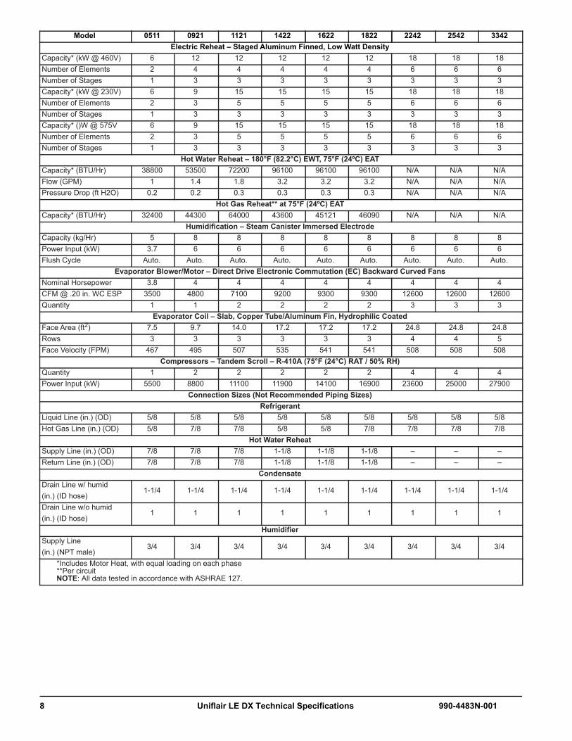
Model 0511 0921 1121 1422 1622 1822 2242 2542 3342Electric Reheat – Staged Aluminum Finned, Low Watt Density
Capacity* (kW @ 460V) 6 12 12 12 12 12 18 18 18Number of Elements 2 4 4 4 4 4 6 6 6Number of Stages 1 3 3 3 3 3 3 3 3Capacity* (kW @ 230V) 6 9 15 15 15 15 18 18 18Number of Elements 2 3 5 5 5 5 6 6 6Number of Stages 1 3 3 3 3 3 3 3 3Capacity* ()W @ 575V 6 9 15 15 15 15 18 18 18Number of Elements 2 3 5 5 5 5 6 6 6Number of Stages 1 3 3 3 3 3 3 3 3
Hot Water Reheat – 180°F (82.2°C) EWT, 75°F (24ºC) EATCapacity* (BTU/Hr) 38800 53500 72200 96100 96100 96100 N/A N/A N/AFlow (GPM) 1 1.4 1.8 3.2 3.2 3.2 N/A N/A N/APressure Drop (ft H2O) 0.2 0.2 0.3 0.3 0.3 0.3 N/A N/A N/A
Hot Gas Reheat** at 75°F (24ºC) EATCapacity* (BTU/Hr) 32400 44300 64000 43600 45121 46090 N/A N/A N/A
Humidification – Steam Canister Immersed Electrode Capacity (kg/Hr) 5 8 8 8 8 8 8 8 8Power Input (kW) 3.7 6 6 6 6 6 6 6 6Flush Cycle Auto. Auto. Auto. Auto. Auto. Auto. Auto. Auto. Auto.
Evaporator Blower/Motor – Direct Drive Electronic Commutation (EC) Backward Curved FansNominal Horsepower 3.8 4 4 4 4 4 4 4 4CFM @ .20 in. WC ESP 3500 4800 7100 9200 9300 9300 12600 12600 12600Quantity 1 1 2 2 2 2 3 3 3
Evaporator Coil – Slab, Copper Tube/Aluminum Fin, Hydrophilic CoatedFace Area (ft2) 7.5 9.7 14.0 17.2 17.2 17.2 24.8 24.8 24.8Rows 3 3 3 3 3 3 4 4 5Face Velocity (FPM) 467 495 507 535 541 541 508 508 508
Compressors – Tandem Scroll – R-410A (75°F (24°C) RAT / 50% RH)Quantity 1 2 2 2 2 2 4 4 4Power Input (kW) 5500 8800 11100 11900 14100 16900 23600 25000 27900
Connection Sizes (Not Recommended Piping Sizes)Refrigerant
Liquid Line (in.) (OD) 5/8 5/8 5/8 5/8 5/8 5/8 5/8 5/8 5/8Hot Gas Line (in.) (OD) 5/8 7/8 7/8 5/8 5/8 7/8 7/8 7/8 7/8
Hot Water ReheatSupply Line (in.) (OD) 7/8 7/8 7/8 1-1/8 1-1/8 1-1/8 – – –Return Line (in.) (OD) 7/8 7/8 7/8 1-1/8 1-1/8 1-1/8 – – –
CondensateDrain Line w/ humid(in.) (ID hose)
1-1/4 1-1/4 1-1/4 1-1/4 1-1/4 1-1/4 1-1/4 1-1/4 1-1/4
Drain Line w/o humid (in.) (ID hose)
1 1 1 1 1 1 1 1 1
HumidifierSupply Line (in.) (NPT male)
3/4 3/4 3/4 3/4 3/4 3/4 3/4 3/4 3/4
*Includes Motor Heat, with equal loading on each phase**Per circuitNOTE: All data tested in accordance with ASHRAE 127.
8 Uniflair LE DX Technical Specifications 990-4483N-001

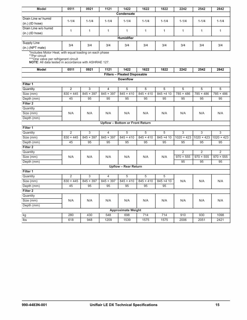
Model 0511 0921 1121 1422 1622 1822 2242 2542 3342Filters - Pleated Disposable
DownflowFilter 1Quantity 2 3 4 5 5 5 5 5 5Size (mm) 830 × 445 845 × 397 845 × 397 845 × 410 845 × 410 845 ×4 10 785 × 486 785 × 486 785 × 486Depth (mm) 45 95 95 95 95 95 95 95 95Filter 2Quantity
N/A N/A N/A N/A N/A N/A N/A N/A N/ASize (mm)Depth (mm)
Upflow – Bottom or Front ReturnFilter 1Quantity 2 3 4 5 5 5 3 3 3Size (mm) 830 × 445 845 × 397 845 × 397 845 × 410 845 × 410 845 ×4 10 1020 × 423 1020 × 423 1020 × 423Depth (mm) 45 95 95 95 95 95 95 95 95Filter 2Quantity
N/A N/A N/A N/A N/A N/A2 2 2
Size (mm) 970 × 555 970 × 555 970 × 555Depth (mm) 95 95 95
Upflow – Rear ReturnFilter 1Quantity 2 3 4 5 5 5
N/A N/A N/ASize (mm) 830 × 445 845 × 397 845 × 397 845 × 410 845 × 410 845 ×4 10Depth (mm) 45 95 95 95 95 95Filter 2Quantity
N/A N/A N/A N/A N/A N/A N/A N/A N/ASize (mm) Depth (mm)
Approximate Weightkg 430 430 548 698 714 714 910 930 1098lbs 618 948 1209 1539 1575 1575 2006 2051 2421
990-4483N-001 Uniflair LE DX Technical Specifications 9

Water-Cooled DX Units (TD/UWV)0% propylene glycol
Model 0511 0921 1121 1422 1622 1822 2242 2542 2842
Net DX Cooling Capacity Data
75°F DB, 61°F WB, 52°F DP (23.9°C DB, 16.1°C WB, 11.1°C DP) 44.6% RH
TotalBTU/Hr 55000 83000 117000 127000 131000 156000 229000 235000 254000
kW 16.0 24.4 34.3 37.2 38.3 45.7 67.1 69.0 74.4
SensibleBTU/Hr 55000 82000 117000 127000 131000 156000 210000 235000 254000
kW 16.0 24.1 34.3 37.2 38.3 45.7 61.6 69.0 74.4
80°F DB, 63°F WB, 52°F DP (26.7°C DB, 17.1°C WB, 11.1°C DP) 37.8% RH
Total BTU/Hr 57000 85000 123000 135000 139000 164000 233000 247000 269000
kW 16.8 24.9 36.0 39.5 40.6 48.0 68.4 72.5 78.8
SensibleBTU/Hr 57000 85000 123000 135000 139000 164000 233000 247000 269000
kW 16.8 24.9 36.0 39.5 40.6 48.0 68.4 72.5 78.8
85°F DB, 64°F WB, 52°F DP (26.7°C DB, 18°C WB, 11.1°C DP) 32.2% RH
Total BTU/Hr 60000 89000 129000 143000 146000 172000 246000 260000 284000
kW 17.7 26.0 37.7 41.8 42.8 50.3 72.1 76.1 83.2
SensibleBTU/Hr 60000 89000 129000 143000 146000 172000 246000 260000 284000
kW 17.7 26.0 37.7 41.8 42.8 50.3 72.1 76.1 83.2
NOTE: All values are accurate to +/– 5% and based on nominal fan speed with standard filterNOTE: Contact the local sales representative for special conditionsNOTE: All data tested in accordance with ASHRAE 127.
10 Uniflair LE DX Technical Specifications 990-4483N-001

Model 0511 0921 1121 1422 1622 1822 2242 2542 2842Electric Reheat – Staged Aluminum Finned, Low Watt Density
Capacity* (kW @ 460V) 6 12 12 12 12 12 18 18 18Number of Elements 2 4 4 4 4 4 6 6 6Number of Stages 1 3 3 3 3 3 3 3 3Capacity* (kW @ 230V) 6 9 15 15 15 15 18 18 18Number of Elements 2 3 5 5 5 5 6 6 6Number of Stages 1 3 3 3 3 3 3 3 3Capacity* (kW @ 575V) 6 9 15 15 15 15 18 18 18Number of Elements 2 3 5 5 5 5 6 6 6Number of Stages 1 3 3 3 3 3 3 3 3
Hot Water Reheat – 180°F (82.2°C) EWT, 75°F (24°C) EATCapacity* (BTU/Hr (kW)) 38800 53500 72200 96100 96100 96100 N/A N/A N/AFlow (GPM) 1 1.4 1.8 3.2 3.2 3.2 N/A N/A N/APressure Drop (ft H2O) 0.2 0.2 0.3 0.3 0.3 0.3 N/A N/A N/A
Hot Gas Reheat with water 95°F (35°C) LWT, 86°F (30°C) EWT, 75°F (24°C) EATCapacity * (BTU/Hr) 31200 43000 61700 39800 43300 43300 N/A N/A N/A
Humidification – Steam Canister Immersed Electrode Capacity (kg/Hr) 5 8 8 8 8 8 8 8 8Power Input (kW) 3.7 6 6 6 6 6 6 6 6Flush Cycle Auto. Auto. Auto. Auto. Auto. Auto. Auto. Auto. Auto.
Evaporator Blower/Motor – Direct Drive Electronic Commutation (EC) Backward Curved FansNominal Horsepower 3.8 4 4 4 4 4 4 4 4CFM @ .20 in WC ESP 3500 4800 7100 9200 9300 9300 12600 12600 12600Quantity 1 1 2 2 2 2 3 3 3
Evaporator Coil – Slab, Copper Tube/Aluminum Fin, Hydrophilic CoatedFace Area (ft²) 7.5 9.7 14.0 17.2 17.2 17.2 24.8 24.8 24.8Rows 3 3 3 3 3 3 4 4 5Face Velocity (FPM) 467 495 507 535 541 541 508 508 508
Compressors – Tandem Scroll – R-410A (75°F (24°C) RAT / 50% RH)Quantity 1 2 2 2 2 2 4 4 4Power Input (Watts) 4700 7500 9700 10200 12100 14300 16100 18500 18100
Water Cooled Condenser Data – 0% GlycolFlow (GPM @ 85°F EWT / 95°F LWT)
16.0 24.5 32.4 40.0 44.5 47.8 70.1 74.5 80.1
Brazed Plate** Pressure Drop (ft H2O)
4.3 3.7 4.2 2.6 3.1 3.6 14.5 16.2 13.0
Valve Pressure Drop (ft H2O)
3.0 3.4 6.0 2.3 2.8 3.3 7.0 8.0 9.2
Optional Head Pressure Control – Water Regulating Valves, 350 PSIG (Factory Installed)***Optional 2-Way 2-Way 2-Way 2-Way 2-Way 2-Way 2-Way 2-Way 2-WayOptional 3-Way 3-Way 3-Way 3-Way 3-Way 3-Way 3-Way 3-Way 3-Way
Connection Sizes (Not Recommended Piping Sizes)Condenser
In/Out (in.) (OD) 1-1/8 1-3/8 1-3/8 1-5/8 1-5/8 1-5/8 1-5/8 1-5/8 1-5/8Hot Water Reheat
Supply Line (in.) (OD) 7/8 7/8 7/8 1-1/8 1-1/8 1-1/8 – – –Return Line (in.) (OD) 7/8 7/8 7/8 1-1/8 1-1/8 1-1/8 – – –
CondensateDrain Line w/ humid (in.) (ID hose)
1-1/4 1-1/4 1-1/4 1-1/4 1-1/4 1-1/4 1-1/4 1-1/4 1-1/4
Drain Line w/o humid (in.) (ID hose)
1 1 1 1 1 1 1 1 1
*Includes Motor Heat, with equal loading on each phase**Per circuit***One valve per refrigerant circuitNOTE: All data tested in accordance with ASHRAE 127.
990-4483N-001 Uniflair LE DX Technical Specifications 11

HumidifierSupply Line (in.) (NPT male)
3/4 3/4 3/4 3/4 3/4 3/4 3/4 3/4 3/4
Filters (MERV 8) – Pleated DisposableDownflow
Filter 1Quantity 2 3 4 5 5 5 5 5 5Size (mm) 830 × 445 845 × 397 845 × 397 845 × 410 845 × 410 845 ×4 10 785 × 486 785 × 486 785 × 486Depth (mm) 45 95 95 95 95 95 95 95 95Filter 2Quantity
N/A N/A N/A N/A N/A N/A N/A N/A N/ASize (mm)Depth (mm)
Upflow – Bottom or Front ReturnFilter 1Quantity 2 3 4 5 5 5 3 3 3Size (mm) 830 × 445 845 × 397 845 × 397 845 × 410 845 × 410 845 ×4 10 1020 × 423 1020 × 423 1020 × 423Depth (mm) 45 95 95 95 95 95 95 95 95Filter 2Quantity
N/A N/A N/A N/A N/A N/A2 2 2
Size (mm) 970 × 555 970 × 555 970 × 555Depth (mm) 95 95 95
Upflow – Rear ReturnFilter 1Quantity 2 3 4 5 5 5
N/A N/A N/ASize (mm) 830 × 445 845 × 397 845 × 397 845 × 410 845 × 410 845 ×4 10Depth (mm) 45 95 95 95 95 95Filter 2Quantity
N/A N/A N/A N/A N/A N/A N/A N/A N/ASize (mm) Depth (mm)
Approximate Weightkg 280 430 548 698 714 714 910 930 1098lbs 618 948 1209 1539 1575 1575 2006 2051 2421
Model 0511 0921 1121 1422 1622 1822 2242 2542 2842
*Includes Motor Heat, with equal loading on each phase**Per circuit***One valve per refrigerant circuitNOTE: All data tested in accordance with ASHRAE 127.
12 Uniflair LE DX Technical Specifications 990-4483N-001

40% propylene glycolModel 0511 0921 1121 1422 1622 1822 2242 2542 2842
Net DX Cooling Capacity Data
75°F DB, 61°F WB, 52°F DP (23.9°C DB, 16.1°C WB, 11.1°C DP) 44.6% RH
TotalBTU/Hr 54000 82000 116000 126000 129000 154000 228000 234000 253000
kW 15.8 24.0 33.9 36.9 37.8 45.2 66.8 68.5 74.1
SensibleBTU/Hr 54000 82000 116000 126000 129000 154000 210000 234000 253000
kW 15.8 24.0 33.9 36.9 37.8 45.2 61.6 68.5 74.1
80°F DB, 63°F WB, 52°F DP (26.7°C DB, 17.1°C WB, 11.1°C DP) 37.8% RH
Total BTU/Hr 57000 84000 121000 133000 137000 162000 232000 246000 268000
kW 16.6 24.6 35.6 39.1 40.0 47.5 68.1 72.1 78.4
SensibleBTU/Hr 57000 84000 121000 133000 137000 162000 232000 246000 268000
kW 16.6 24.6 35.6 39.1 40.0 47.5 68.1 72.1 78.4
85°F DB, 64°F WB, 52°F DP (26.7°C DB, 18°C WB, 11.1°C DP) 32.2% RH
Total BTU/Hr 59000 88000 127000 141000 144000 170000 245000 258000 282000
kW 17.4 25.7 37.3 41.3 42.2 49.8 71.8 75.6 82.7
SensibleBTU/Hr 59000 88000 127000 141000 144000 170000 245000 258000 282000
kW 17.4 25.7 37.3 41.3 42.2 49.8 71.8 75.6 82.7
NOTE: All values are accurate to +/– 5% and based on nominal fan speed with standard filterNOTE: Contact the local sales representative for special conditionsNOTE: All data tested in accordance with ASHRAE 127.
990-4483N-001 Uniflair LE DX Technical Specifications 13

Model 0511 0921 1121 1422 1622 1822 2242 2542 2842Electric Reheat – Staged Aluminum Finned, Low Watt Density
Capacity* (kW @ 460V) 6 12 12 12 12 12 18 18 18Number of Elements 2 4 4 4 4 4 6 6 6Number of Stages 1 3 3 3 3 3 3 3 3Capacity* (kW @ 230V) 6 9 15 15 15 15 18 18 18Number of Elements 2 3 5 5 5 5 6 6 6Number of Stages 1 3 3 3 3 3 3 3 3Capacity* (kW @ 575V) 6 9 15 15 15 15 18 18 18Number of Elements 2 3 5 5 5 5 6 6 6Number of Stages 1 3 3 3 3 3 3 3 3
Hot Water Reheat – 180°F (82.2°C) EWT, 75°F (24°C) EATCapacity* (BTU/Hr (kW)) 38800 53500 72200 96100 96100 96100 N/A N/A N/AFlow (GPM) 1 1.4 1.8 3.2 3.2 3.2 N/A N/A N/APressure Drop (ft H2O) 0.2 0.2 0.3 0.3 0.3 0.3 N/A N/A N/A
Hot Gas Reheat** with water 95°F (35°C) LWT, 86°F (30°C) EWT, 75°F (24°C) EATCapacity* (BTU/Hr) 31200 43000 61700 39800 43300 43300 N/A N/A N/A
Humidification – Steam Canister Immersed Electrode Capacity (kg/Hr) 5 8 8 8 8 8 8 8 8Power Input (kW) 3.7 6 6 6 6 6 6 6 6Flush Cycle Auto. Auto. Auto. Auto. Auto. Auto. Auto. Auto. Auto.
Evaporator Blower/Motor – Direct Drive Electronic Commutation (EC) Backward Curved FansNominal Horsepower 3.8 4 4 4 4 4 4 4 4CFM @ .20 in WC ESP 3500 4800 7100 9200 9300 9300 12600 12600 12600Quantity 1 1 2 2 2 2 3 3 3
Evaporator Coil –Slab, Copper Tube/Aluminum Fin, Hydrophilic CoatedFace Area (ft2) 7.5 9.7 14.0 17.2 17.2 17.2 24.8 24.8 24.8Rows 3 3 3 3 3 3 4 4 5Face Velocity (FPM) 467 495 507 535 541 541 508 508 508
Compressors – Tandem Scroll – R-410A (75°F (24°C) RAT / 50% RH)Quantity 1 2 2 2 2 2 4 4 4Power Input (Watts) 4800 7500 9700 10200 12100 14300 18800 28900 21200
Water Cooled Condenser Data – 40% GlycolFlow (GPM @ 105°F EWT / 115°F LWT)
17.0 26.2 34.1 42.9 47.8 51.0 74.9 79.9 86.9
Brazed Plate Pressure Drop (ft. of H2O)
5.4 4.8 5.3 3.3 4.0 4.6 17.1 19.3 15.6
Valve Pressure Drop (ft. of H2O)*
3.6 4.2 7.1 2.8 3.5 3.9 8.5 9.7 11.5
Flow (GPM @ 110°F EWT / 120°F LWT)
16.4 25.4 32.9 41.6 46.3 49.5 72.5 77.3 83.7
Brazed Plate Pressure Drop (ft. of H2O)
5.0 4.5 4.9 3.1 3.8 4.2 15.9 17.9 14.5
Valve Pressure Drop (ft. of H2O)*
3.3 3.9 6.6 2.6 3.3 3.7 8.0 9.1 10.6
Head Pressure Control – Water Regulating Valves, 350 PSIG (Factory Installed)***Optional 2-Way 2-Way 2-Way 2-Way 2-Way 2-Way 2-Way 2-Way 2-WayOptional 3-Way 3-Way 3-Way 3-Way 3-Way 3-Way 3-Way 3-Way 3-Way
Connection Sizes (Not Recommended Piping Sizes)Condenser
In/Out (in.) (OD) 1-1/8 1-3/8 1-3/8 1-5/8 1-5/8 1-5/8 1-5/8 1-5/8 1-5/8Hot Water Reheat
Supply Line (in.) (OD) 7/8 7/8 7/8 1-1/8 1-1/8 1-1/8 – – –Return Line (in.) (OD) 7/8 7/8 7/8 1-1/8 1-1/8 1-1/8 – – –
*Includes Motor Heat, with equal loading on each phase**Per circuit***One valve per refrigerant circuitNOTE: All data tested in accordance with ASHRAE 127.
14 Uniflair LE DX Technical Specifications 990-4483N-001
CondensateDrain Line w/ humid (in.) (ID hose)
1-1/4 1-1/4 1-1/4 1-1/4 1-1/4 1-1/4 1-1/4 1-1/4 1-1/4
Drain Line w/o humid(in.) (ID hose)
1 1 1 1 1 1 1 1 1
HumidifierSupply Line (in.) (NPT male)
3/4 3/4 3/4 3/4 3/4 3/4 3/4 3/4 3/4
Model 0511 0921 1121 1422 1622 1822 2242 2542 2842Filters – Pleated Disposable
DownflowFilter 1Quantity 2 3 4 5 5 5 5 5 5Size (mm) 830 × 445 845 × 397 845 × 397 845 × 410 845 × 410 845 ×4 10 785 × 486 785 × 486 785 × 486Depth (mm) 45 95 95 95 95 95 95 95 95Filter 2Quantity
N/A N/A N/A N/A N/A N/A N/A N/A N/ASize (mm)Depth (mm)
Upflow – Bottom or Front ReturnFilter 1Quantity 2 3 4 5 5 5 3 3 3Size (mm) 830 × 445 845 × 397 845 × 397 845 × 410 845 × 410 845 ×4 10 1020 × 423 1020 × 423 1020 × 423Depth (mm) 45 95 95 95 95 95 95 95 95Filter 2Quantity
N/A N/A N/A N/A N/A N/A2 2 2
Size (mm) 970 × 555 970 × 555 970 × 555Depth (mm) 95 95 95
Upflow – Rear ReturnFilter 1Quantity 2 3 4 5 5 5
N/A N/A N/ASize (mm) 830 × 445 845 × 397 845 × 397 845 × 410 845 × 410 845 ×4 10Depth (mm) 45 95 95 95 95 95Filter 2Quantity
N/A N/A N/A N/A N/A N/A N/A N/A N/ASize (mm) Depth (mm)
Approximate Weightkg 280 430 548 698 714 714 910 930 1098lbs 618 948 1209 1539 1575 1575 2006 2051 2421
Model 0511 0921 1121 1422 1622 1822 2242 2542 2842
*Includes Motor Heat, with equal loading on each phase**Per circuit***One valve per refrigerant circuitNOTE: All data tested in accordance with ASHRAE 127.
990-4483N-001 Uniflair LE DX Technical Specifications 15

Twin-Cool Air-Cooled DX Units (TD/UTV) Air-cooled circuit
NOTE: All values are accurate to +/– 5% and based on nominal fan speed with standard filterNOTE: Contact the local sales representative for special conditionsNOTE: All data tested in accordance with ASHRAE 127.
Model 0511 0921 1121 1422 1622 1822 2242 2542 2842
Net DX Cooling Capacity Data
80°F DB, 67°F WB (26.7°CDB, 19.4°C WB) 50% RH
TotalBTU/Hr 58000 87000 116000 154000 168000 171000 241000 244000 280000
kW 17.0 25.5 34.0 45.1 49.2 50.1 70.7 71.6 82.1
SensibleBTU/Hr 58000 87000 116000 154000 168000 171000 180000 181000 193000
kW 17.0 25.5 34.0 45.1 49.2 50.1 52.9 53.2 56.7
75°F DB, 62.5°F WB (23.9°C DB, 16.9°C WB) 50% RH
Total BTU/Hr 56000 92000 115000 145000 162000 168000 228000 232000 263000
kW 16.4 27.0 33.7 42.5 47.5 49.2 66.9 67.9 77.2
SensibleBTU/Hr 56000 85000 114000 145000 155000 155000 179000 180000 192000
kW 16.4 24.9 33.4 42.5 45.4 45.4 52.5 52.8 56.4
75°F DB, 61°F WB (23.9°C DB, 16.1°C WB) 45% RH
Total BTU/Hr 56000 90000 113000 145000 159000 165000 225000 229000 260000
kW 16.4 26.4 33.1 42.5 46.6 48.4 66.1 67.1 76.2
SensibleBTU/Hr 56000 90000 113000 145000 159000 165000 205000 207000 217000
kW 16.4 26.4 33.1 42.5 46.6 48.4 60.2 60.5 63.6
72°F DB, 60°F WB (22.2°C DB, 15.5°C WB) 50% RH
Total BTU/Hr 54000 89000 111000 140000 157000 163000 220000 224000 253000
kW 15.8 26.1 32.5 41.0 46.0 47.8 64.6 65.6 74.3
SensibleBTU/Hr 54000 84000 111000 140000 153000 153000 178000 179000 191000
kW 15.8 24.6 32.5 41.0 44.8 44.8 52.0 52.5 56.0
72°F DB, 58.6°F WB (22.2°C DB, 14.8°C WB) 45% RH
Total BTU/Hr 54000 88000 110000 140000 154000 161000 218000 221000 250000
kW 15.8 25.8 32.2 41.0 45.1 47.2 63.8 64.9 73.4
SensibleBTU/Hr 54000 88000 110000 140000 154000 161000 202000 204000 214000
kW 15.8 25.8 32.2 41.0 45.1 47.2 59.3 59.7 62.8
70°F DB, 58.5°F WB (22.2°C DB, 14.8°C WB) 50% RH
Total BTU/Hr 53000 87000 109000 137000 153000 160000 215000 219000 247000
kW 15.5 25.5 31.9 40.2 44.8 46.9 63.1 64.2 72.4
SensibleBTU/Hr 53000 83000 109000 137000 151000 152000 176000 178000 190000
kW 15.5 24.3 31.9 40.2 44.3 44.5 51.7 52.2 55.7
70°F DB, 57.2°F WB (22.2°C DB, 14°C WB) 45% RH
Total BTU/Hr 53000 86000 108000 137000 151000 158000 213000 217000 244000
kW 15.5 25.2 31.7 40.2 44.3 46.3 62.4 63.5 71.6
SensibleBTU/Hr 53000 86000 108000 137000 151000 158000 200000 201000 212000
kW 15.5 25.2 31.7 40.2 44.3 46.3 58.6 59.0 62.2
16 Uniflair LE DX Technical Specifications 990-4483N-001

Chilled water circuit Model 0511 0921 1121 1422 1622 1822 2242 2542 2842
Net CW Cooling Capacity Data
80°F DB, 67°F WB (26.7°C DB, 19.4°C WB) 50% RH
TotalBTU/Hr 60000 79000 114000 168000 168000 168000 331000 331000 331000
kW 17.6 23.2 33.4 49.2 49.2 49.2 97.0 97.0 97.0
SensibleBTU/Hr 53000 71000 104000 156000 157000 157000 321000 321000 321000
kW 15.5 20.8 30.5 45.7 46.0 46.0 94.1 94.1 94.1
Press. Drop (ft WC)ft WC 10.5 7.2 13.3 11.3 11.3 11.3 23.0 23.0 23.0
kPa 31.3 21.5 39.7 33.7 33.7 33.7 68.7 68.7 68.7
Flow (GPM)GPM 12.6 16.3 23.8 35.0 35.0 35.0 71.2 71.2 71.2
L/s 0.8 1.0 1.5 2.2 2.2 2.2 4.5 4.5 4.5
75°FDB, 62.5°F WB (23.9°C DB, 16.9°C WB) 50% RH
Total BTU/Hr 44000 59000 87000 130000 130000 130000 270000 270000 270000
kW 12.9 17.3 25.5 38.1 38.1 38.1 79.2 79.2 79.2
SensibleBTU/Hr 44000 58000 85000 127000 127000 127000 268000 268000 268000
kW 12.9 17.0 24.9 37.2 37.2 37.2 78.5 78.5 78.5
Press. Drop (ft WC)ft WC 6.2 4.3 8.3 7.2 7.2 7.2 15.5 15.5 15.5
kPa 18.5 12.8 24.8 21.5 21.5 21.5 46.3 46.3 46.3
Flow (GPM)GPM 9.4 12.4 18.4 27.4 27.4 27.4 57.7 57.7 57.7
L/s 0.6 0.8 1.2 1.7 1.7 1.7 3.6 3.6 3.6
75ºF DB, 61°F WB (23.9°C DB, 16.1°C WB) 45% RH
Total BTU/Hr 44000 58000 86000 128000 128000 128000 270000 270000 270000
kW 12.9 17.0 25.2 37.5 37.5 37.5 79.2 79.2 79.2
SensibleBTU/Hr 44000 58000 86000 128000 128000 128000 269000 269000 269000
kW 12.9 17.0 25.2 37.5 37.5 37.5 78.8 78.8 78.8
Press. Drop (ft WC)ft WC 6.0 4.3 8.3 7.2 7.2 7.2 15.5 15.5 15.5
kPa 17.9 12.8 24.8 21.5 21.5 21.5 46.3 46.3 46.3
Flow (GPM)GPM 9.2 12.4 18.4 27.4 27.4 27.4 57.7 57.7 57.7
L/s 0.6 0.8 1.2 1.7 1.7 1.7 3.6 3.6 3.6
72° F DB, 60°F WB (22.2°C DB, 15.5°C WB) 50% RH
Total BTU/Hr 37000 48000 73000 109000 109000 109000 234000 234000 234000
kW 10.8 14.1 21.4 31.9 31.9 31.9 68.5 68.5 68.5
SensibleBTU/Hr 37000 48000 72000 109000 109000 109000 232000 232000 232000
kW 10.8 14.1 21.1 31.9 31.9 31.9 68.1 68.1 68.1
Press. Drop (ft WC)ft WC 4.5 3.1 6.1 5.3 5.3 5.3 11.9 11.9 11.9
kPa 13.4 9.3 18.2 15.8 15.8 15.8 35.5 35.5 35.5
Flow (GPM)GPM 7.9 10.3 15.6 23.4 23.4 23.4 50.1 50.1 50.1
L/s 0.5 0.6 1.0 1.5 1.5 1.5 3.2 3.2 3.2
NOTE: All values are accurate to +/– 5% and based on nominal fan speed with standard filter.NOTE: Contact the local sales representative for special conditions.NOTE: All data tested in accordance with ASHRAE 127.
990-4483N-001 Uniflair LE DX Technical Specifications 17

72°F DB, 58.6°F WB (22.2°C DB, 14.8°C WB) 45% RH
Total BTU/Hr 37000 49000 73000 109000 109000 109000 234000 234000 234000
kW 10.8 14.4 21.4 31.9 31.9 31.9 68.5 68.5 68.5
SensibleBTU/Hr 37000 49000 73000 109000 109000 109000 233000 233000 233000
kW 10.8 14.4 21.4 31.9 31.9 31.9 68.3 68.3 68.3
Press. Drop (ft WC)ft WC 4.5 3.1 6.1 5.3 5.3 5.3 11.9 11.9 11.9
kPa 13.4 9.3 18.2 15.8 15.8 15.8 35.5 35.5 35.5
Flow (GPM)GPM 7.9 10.3 15.6 23.4 23.4 23.4 50.1 50.1 50.1
L/s 0.5 0.6 1.0 1.5 1.5 1.5 3.2 3.2 3.2
70°F DB, 58.5°F WB (22.2°C DB, 14.8°C WB) 50% RH
Total BTU/Hr 33000 40000 64000 97000 97000 97000 210000 210000 210000
kW 9.7 11.7 18.8 28.4 28.4 28.4 61.4 61.4 61.4
SensibleBTU/Hr 33000 40000 64000 97000 97000 97000 209000 209000 209000
kW 9.7 11.7 18.8 28.4 28.4 28.4 61.2 61.2 61.2
Press. Drop (ft WC)ft WC 3.7 2.2 4.9 4.3 4.3 4.3 9.9 9.9 9.9
kPa 11.0 6.6 14.6 12.8 12.8 12.8 29.6 29.6 29.6
Flow (GPM)GPM 7.1 8.6 13.9 21.0 21.0 21.0 45.4 45.4 45.4
L/s 0.4 0.5 0.9 1.3 1.3 1.3 2.9 2.9 2.9
70°F DB, 57.2°FWB (22.2°C DB, 14°C WB) 45% RH
Total BTU/Hr 33000 40000 64000 97000 97000 97000 210000 210000 210000
kW 9.7 11.7 18.8 28.4 28.4 28.4 61.4 61.4 61.4
SensibleBTU/Hr 33000 40000 64000 97000 97000 97000 210000 210000 210000
kW 9.7 11.7 18.8 28.4 28.4 28.4 61.4 61.4 61.4
Press. Drop (ft WC)ft WC 3.7 2.2 4.9 4.3 4.3 4.3 9.9 9.9 9.9
kPa 11.0 6.6 14.6 12.8 12.8 12.8 29.6 29.6 29.6
Flow (GPM)GPM 7.1 8.6 13.9 21.0 21.0 21.0 45.4 45.4 45.4
L/s 0.4 0.5 0.9 1.3 1.3 1.3 2.9 2.9 2.9
Model 0511 0921 1121 1422 1622 1822 2242 2542 2842
NOTE: All values are accurate to +/– 5% and based on nominal fan speed with standard filter.NOTE: Contact the local sales representative for special conditions.NOTE: All data tested in accordance with ASHRAE 127.
18 Uniflair LE DX Technical Specifications 990-4483N-001
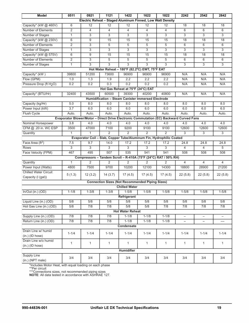
Model 0511 0921 1121 1422 1622 1822 2242 2542 2842Electric Reheat – Staged Aluminum Finned, Low Watt Density
Capacity* (kW @ 460V) 6 12 12 12 12 12 18 18 18Number of Elements 2 4 4 4 4 4 6 6 6Number of Stages 1 3 3 3 3 3 3 3 3Capacity* (kW @ 230V) 6 9 15 15 15 15 18 18 18Number of Elements 2 3 5 5 5 5 6 6 6Number of Stages 1 3 3 3 3 3 3 3 3Capacity* (kW @ 575V) 6 9 15 15 15 15 18 18 18Number of Elements 2 3 5 5 5 5 6 6 6Number of Stages 1 3 3 3 3 3 3 3 3
Hot Water Reheat – 180°F (82.2ºC) EWT, 75°F EATCapacity* (kW ) 39800 51200 73600 96900 96900 96900 N/A N/A N/AFlow (GPM) 1.0 1.3 1.9 2.2 2.2 2.2 N/A N/A N/APressure Drop (ft H2O) 0.2 0.2 0.3 0.2 0.2 0.2 N/A N/A N/A
Hot Gas Reheat at 75°F (24°C) EATCapacity* (BTU/Hr) 32400 43500 60500 39300 40200 40800 N/A N/A N/A
Humidification – Steam Canister Immersed Electrode Capacity (kg/Hr) 5.0 8.0 8.0 8.0 8.0 8.0 8.0 8.0 8.0Power Input (kW) 3.7 6.0 6.0 6.0 6.0 6.0 6.0 6.0 6.0Flush Cycle Auto. Auto. Auto. Auto. Auto. Auto. Auto. Auto. Auto.
Evaporator Blower/Motor – Direct Drive Electronic Commutation (EC) Backward Curved FansNominal Horsepower 3.8 4.0 4.0 4.0 4.0 4.0 4.0 4.0 4.0CFM @ .20 in. WC ESP 3500 47000 7100 9200 9100 9100 12600 12600 12600Quantity 1 1 2 2 2 2 3 3 3
Evaporator Coil – Slab, Copper Tube/Aluminum Fin, Hydrophilic CoatedFace Area (ft2) 7.5 9.7 14.0 17.2 17.2 17.2 24.8 24.8 24.8Rows 3 3 3 3 3 3 4 4 5Face Velocity (FPM) 467 495 507 535 541 541 508 508 508
Compressors – Tandem Scroll – R-410A (75°F (24°C) RAT / 50% RH)Quantity 1 2 2 2 2 2 4 4 4Power Input (Watts) 4800 7500 9700 10200 12100 14300 18800 28900 21200Chilled Water Circuit Capacity (l (gal))
5 (1.3) 12 (3.2) 14 (3.7) 17 (4.5) 17 (4.5) 17 (4.5) 22 (5.8) 22 (5.8) 22 (5.8)
Connection Sizes (Not Recommended Piping Sizes)Chilled Water
In/Out (in.) (OD) 1-1/8 1-3/8 1-3/8 1-5/8 1-5/8 1-5/8 1-5/8 1-5/8 1-5/8Refrigerant
Liquid Line (in.) (OD) 5/8 5/8 5/8 5/8 5/8 5/8 5/8 5/8 5/8Hot Gas Line (in.) (OD) 5/8 7/8 7/8 5/8 5/8 7/8 7/8 7/8 7/8
Hot Water ReheatSupply Line (in.) (OD) 7/8 7/8 7/8 1-1/8 1-1/8 1-1/8 – – –Return Line (in.) (OD) 7/8 7/8 7/8 1-1/8 1-1/8 1-1/8 – – ––
CondensateDrain Line w/ humid (in.) (ID hose)
1-1/4 1-1/4 1-1/4 1-1/4 1-1/4 1-1/4 1-1/4 1-1/4 1-1/4
Drain Line w/o humid(in.) (ID hose)
1 1 1 1 1 1 1 1 1
HumidifierSupply Line (in.) (NPT male)
3/4 3/4 3/4 3/4 3/4 3/4 3/4 3/4 3/4
*Includes Motor Heat, with equal loading on each phase**Per circuit***Connections sizes, not recommended piping sizesNOTE: All data tested in accordance with ASHRAE 127.
990-4483N-001 Uniflair LE DX Technical Specifications 19

Model 0511 0921 1121 1422 1622 1822 2242 2542 2842Filters – Pleated Disposable
DownflowFilter 1Quantity 2 3 3 2 2 2 5 5 5Size (mm) 830 x 421 845 x 376 845 x 376 845 x 376 845 x 376 845 x 376 785 x 486 785 x 486 785 x 486Depth (mm) 45 95 95 95 95 95 95 95 95Filter 2Quantity
N/A N/A1 3 3 3
N/A N/A N/ASize (mm) 845 x 397 845 x 410 845 x 410 845 x 410Depth (mm) 95 95 95 95
Upflow – Bottom or Front ReturnFilter 1Quantity 2 3 3 2 2 2 3 3 3Size (mm) 830 x 421 845 x 376 845 x 375 845 x 376 845 x 376 845 x 376 1020 x 410 1020 x 410 1020 x 410Depth (mm) 45 95 95 95 95 95 95 95 95Filter 2Quantity
N/A N/A1 3 3 3 2 2 2
Size (mm) 845 x 397 845 x 410 845 x 410 845 x 410 970 x 555 970 x 555 970 x 555Depth (mm) 95 95 95 95 95 95 95
Upflow – Rear ReturnFilter 1Quantity 2 3 3 2 2 2 3 3 3Size (mm) 830 x 421 845 x 376 845 x 375 845 x 376 845 x 376 845 x 376 1020 x 410 1020 x 410 1020 x 410Depth (mm) 45 95 95 95 95 95 95 95 95Filter 2Quantity
N/A N/A1 3 3 3 2 2 2
Size (mm) 845 x 397 845 x 410 845 x 410 845 x 410 970 x 555 970 x 555 970 x 555Depth (mm) 95 95 95 95 95 95 95
Approximate Weightkg 280 430 548 698 714 714 910 930 1098lbs 618 948 1209 1539 1575 1575 2006 2051 2421
20 Uniflair LE DX Technical Specifications 990-4483N-001
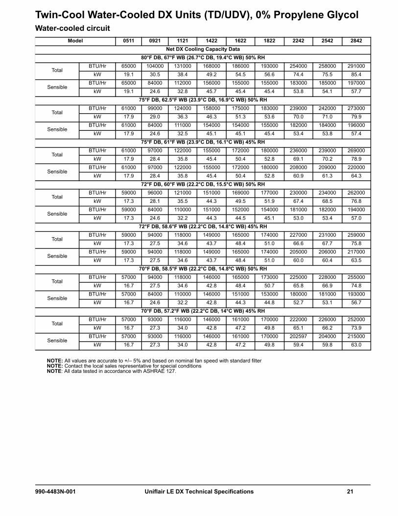
Twin-Cool Water-Cooled DX Units (TD/UDV), 0% Propylene GlycolWater-cooled circuit
NOTE: All values are accurate to +/– 5% and based on nominal fan speed with standard filterNOTE: Contact the local sales representative for special conditionsNOTE: All data tested in accordance with ASHRAE 127.
Model 0511 0921 1121 1422 1622 1822 2242 2542 2842Net DX Cooling Capacity Data
80°F DB, 67°F WB (26.7°C DB, 19.4°C WB) 50% RH
TotalBTU/Hr 65000 104000 131000 168000 186000 193000 254000 258000 291000
kW 19.1 30.5 38.4 49.2 54.5 56.6 74.4 75.5 85.4
SensibleBTU/Hr 65000 84000 112000 156000 155000 155000 183000 185000 197000
kW 19.1 24.6 32.8 45.7 45.4 45.4 53.8 54.1 57.775°F DB, 62.5°F WB (23.9°C DB, 16.9°C WB) 50% RH
Total BTU/Hr 61000 99000 124000 158000 175000 183000 239000 242000 273000
kW 17.9 29.0 36.3 46.3 51.3 53.6 70.0 71.0 79.9
SensibleBTU/Hr 61000 84000 111000 154000 154000 155000 182000 184000 196000
kW 17.9 24.6 32.5 45.1 45.1 45.4 53.4 53.8 57.475°F DB, 61°F WB (23.9°C DB, 16.1°C WB) 45% RH
Total BTU/Hr 61000 97000 122000 155000 172000 180000 236000 239000 269000
kW 17.9 28.4 35.8 45.4 50.4 52.8 69.1 70.2 78.9
SensibleBTU/Hr 61000 97000 122000 155000 172000 180000 208000 209000 220000
kW 17.9 28.4 35.8 45.4 50.4 52.8 60.9 61.3 64.372°F DB, 60°F WB (22.2°C DB, 15.5°C WB) 50% RH
Total BTU/Hr 59000 96000 121000 151000 169000 177000 230000 234000 262000
kW 17.3 28.1 35.5 44.3 49.5 51.9 67.4 68.5 76.8
SensibleBTU/Hr 59000 84000 110000 151000 152000 154000 181000 182000 194000
kW 17.3 24.6 32.2 44.3 44.5 45.1 53.0 53.4 57.072°F DB, 58.6°F WB (22.2°C DB, 14.8°C WB) 45% RH
Total BTU/Hr 59000 94000 118000 149000 165000 174000 227000 231000 259000
kW 17.3 27.5 34.6 43.7 48.4 51.0 66.6 67.7 75.8
SensibleBTU/Hr 59000 94000 118000 149000 165000 174000 205000 206000 217000
kW 17.3 27.5 34.6 43.7 48.4 51.0 60.0 60.4 63.570°F DB, 58.5°F WB (22.2°C DB, 14.8ºC WB) 50% RH
Total BTU/Hr 57000 94000 118000 146000 165000 173000 225000 228000 255000
kW 16.7 27.5 34.6 42.8 48.4 50.7 65.8 66.9 74.8
SensibleBTU/Hr 57000 84000 110000 146000 151000 153000 180000 181000 193000
kW 16.7 24.6 32.2 42.8 44.3 44.8 52.7 53.1 56.770°F DB, 57.2°F WB (22.2°C DB, 14°C WB) 45% RH
Total BTU/Hr 57000 93000 116000 146000 161000 170000 222000 226000 252000
kW 16.7 27.3 34.0 42.8 47.2 49.8 65.1 66.2 73.9
SensibleBTU/Hr 57000 93000 116000 146000 161000 170000 202597 204000 215000
kW 16.7 27.3 34.0 42.8 47.2 49.8 59.4 59.8 63.0
990-4483N-001 Uniflair LE DX Technical Specifications 21

Chilled water circuit Model 0511 0921 1121 1422 1622 1822 2242 2542 2842
Net CW Cooling Capacity Data 80°F DB, 67°F WB (26.7°C DB, 19.4°C WB) 50% RH
TotalBTU/Hr 60000 79000 114000 168000 168000 168000 337000 337000 337000
kW 17.6 23.2 33.4 49.2 49.2 49.2 98.6 98.6 98.6
SensibleBTU/Hr 53000 71000 104000 156000 157000 157000 322000 322000 322000
kW 15.5 20.8 30.5 45.7 46.0 46.0 94.3 94.3 94.3
Press. Dropft WC 10.5 7.2 13.3 11.3 11.3 11.3 23 23 23kPa 31.3 21.5 39.7 33.7 33.7 33.7 68.7 68.7 68.7
FlowGPM 12.6 16.3 23.8 35.0 35.0 35.0 71.2 71.2 71.2L/s 0.8 1.0 1.5 2.2 2.2 2.2 4.5 4.5 4.5
75°F DB, 62.5°F WB (23.9°C DB, 16.9°C WB) 50% RH
Total BTU/Hr 45000 59000 86000 130000 130000 130000 270000 270000 270000
kW 13.2 17.3 25.2 38.1 38.1 38.1 79.2 79.2 79.2
SensibleBTU/Hr 43000 58000 85000 127000 127000 127000 268000 268000 268000
kW 12.6 17.0 24.9 37.2 37.2 37.2 78.5 78.5 78.5
Press. Dropft WC 6.2 4.3 8.3 7.2 7.2 7.2 15.5 15.5 15.5kPa 18.5 12.8 24.8 21.5 21.5 21.5 46.3 46.3 46.3
FlowGPM 9.4 12.4 18.4 27.4 27.4 27.4 57.7 57.7 57.7L/s 0.6 0.8 1.2 1.7 1.7 1.7 3.6 3.6 3.6
75°F DB, 61°F WB (23.9°C DB, 16.1°C WB) 45% RH
Total BTU/Hr 44000 58000 85000 128000 128000 128000 270000 270000 270000
kW 12.9 17.0 24.9 37.5 37.5 37.5 79.2 79.2 79.2
SensibleBTU/Hr 44000 58000 85000 128000 128000 128000 269000 269000 269000
kW 12.9 17.0 24.9 37.5 37.5 37.5 78.8 78.8 78.8
Press. Dropft WC 6.0 4.3 8.3 7.2 7.2 7.2 15.5 15.5 15.5kPa 17.9 12.8 24.8 21.5 21.5 21.5 46.3 46.3 46.3
FlowGPM 9.2 12.4 18.4 27.4 27.4 27.4 57.7 57.7 57.7L/s 0.6 0.8 1.2 1.7 1.7 1.7 3.6 3.6 3.6
72°F DB, 60°F WB (22.2°C DB, 15.5°C WB) 50% RH
Total BTU/Hr 37000 48000 72000 109000 109000 109000 234000 234000 234000
kW 10.8 14.1 21.1 31.9 31.9 31.9 68.5 68.5 68.5
SensibleBTU/Hr 37000 48000 72000 109000 109000 109000 232000 232000 232000
kW 10.8 14.1 21.1 31.9 31.9 31.9 68.1 68.1 68.1
Press. Dropft WC 4.5 3.1 6.1 5.3 5.3 5.3 11.9 11.9 11.9kPa 13.4 9.3 18.2 15.8 15.8 15.8 35.5 35.5 35.5
FlowGPM 7.9 10.3 15.6 23.4 23.4 23.4 50.1 50.1 50.1L/s 0.5 0.6 1.0 1.5 1.5 1.5 3.2 3.2 3.2
72ºF DB, 58.6°F WB (22.2°C DB, 14.8°C WB) 45% RH
Total BTU/Hr 37000 49000 72000 109000 109000 109000 234000 234000 234000
kW 10.8 14.4 21.1 31.9 31.9 31.9 68.5 68.5 68.5
SensibleBTU/Hr 37000 49000 72000 109000 109000 109000 233000 233000 233000
kW 10.8 14.4 21.1 31.9 31.9 31.9 68.3 68.3 68.3
Press. Dropft WC 4.5 3.1 6.1 5.3 5.3 5.3 11.9 11.9 11.9kPa 13.4 9.3 18.2 15.8 15.8 15.8 35.5 35.5 35.5
FlowGPM 7.9 10.3 15.6 23.4 23.4 23.4 50.1 50.1 50.1L/s 0.5 0.6 1.0 1.5 1.5 1.5 3.2 3.2 3.2
NOTE: All values are accurate to +/– 5% and based on nominal fan speed with standard filter.NOTE: Contact the local sales representative for special conditions.NOTE: All data tested in accordance with ASHRAE 127.
22 Uniflair LE DX Technical Specifications 990-4483N-001

70°F DB, 58.5°F WB (22.2°C DB, 14.8°C WB) 50% RH
Total BTU/Hr 33000 40000 63000 97000 97000 97000 210000 210000 210000
kW 9.7 11.7 18.5 28.4 28.4 28.4 61.4 61.4 61.4
SensibleBTU/Hr 33000 40000 63000 97000 97000 97000 209000 209000 209000
kW 9.7 11.7 18.5 28.4 28.4 28.4 61.2 61.2 61.2
Press. Dropft WC 3.7 2.2 4.9 4.3 4.3 4.3 9.9 9.9 9.9kPa 11.0 6.6 14.6 12.8 12.8 12.8 29.6 29.6 29.6
FlowGPM 7.1 8.6 13.9 21 21 21 45.4 45.4 45.4L/s 0.4 0.5 0.9 1.3 1.3 1.3 2.9 2.9 2.9
70°F DB, 57.2°F WB (22.2°C DB, 14°C WB) 45% RH
Total BTU/Hr 33000 40000 64000 97000 97000 97000 210000 210000 210000
kW 9.7 11.7 18.8 28.4 28.4 28.4 61.4 61.4 61.4
SensibleBTU/Hr 33000 40000 64000 97000 97000 97000 210000 210000 210000
kW 9.7 11.7 18.8 28.4 28.4 28.4 61.4 61.4 61.4
Press. Dropft WC 3.7 2.2 4.9 4.3 4.3 4.3 9.9 9.9 9.9kPa 11.0 6.6 14.6 12.8 12.8 12.8 29.6 29.6 29.6
FlowGPM 7.1 8.6 13.9 21.0 21.0 21.0 45.4 45.4 45.4L/s 0.4 0.5 0.9 1.3 1.3 1.3 2.9 2.9 2.9
Model 0511 0921 1121 1422 1622 1822 2242 2542 2842
NOTE: All values are accurate to +/– 5% and based on nominal fan speed with standard filter.NOTE: Contact the local sales representative for special conditions.NOTE: All data tested in accordance with ASHRAE 127.
990-4483N-001 Uniflair LE DX Technical Specifications 23

Model 0511 0921 1121 1422 1622 1822 2242 2542 2842Electric Reheat – Staged Aluminum Finned, Low Watt Density
Capacity* (kW @ 460V) 6 12 12 12 12 12 18 18 18Number of Elements 2 4 4 4 4 4 6 6 6Number of Stages 1 3 3 3 3 3 3 3 3Capacity* (kW @ 230V) 6 9 15 15 15 15 18 18 18Number of Elements 2 3 5 5 5 5 6 6 6Number of Stages 1 3 3 3 3 3 3 3 3Capacity* (kW @ 575V) 6 9 15 15 15 15 18 18 18Number of Elements 2 3 5 5 5 5 6 6 6Number of Stages 1 3 3 3 3 3 3 3 3
Hot Water Reheat – 180°F (82.2°C) EWT, 75°F EATCapacity* (BTU/Hr (kW)) 39800 51200 73600 96900 96900 96900 N/A N/A N/AFlow (GPM) 1.0 1.3 1.9 2.2 2.2 2.2 N/A N/A N/APressure Drop (ft H2O) 0.2 0.2 0.3 0.2 0.2 0.2 N/A N/A N/A
Hot Gas Reheat with water 95°F (35°C) LWT, 86°F (30°C) EWT, 75°F (24°C) EATCapacity* (BTU/Hr) 33400 45400 64000 44600 44000 44400 N/A N/A N/A
Humidification – Steam Canister Immersed Electrode Capacity (kg/Hr) 5 8 8 8 8 8 8 8 8Power Input (kW) 3.7 6.0 6.0 6.0 6.0 6.0 6.0 6.0 6.0Flush Cycle Auto. Auto. Auto. Auto. Auto. Auto. Auto. Auto. Auto.
Evaporator Blower/Motor – Direct Drive Electronic Commutation (EC) Backward Curved FansNominal Horsepower 3.8 4.0 4.0 4.0 4.0 4.0 4.0 4.0 4.0CFM @ .20 in. WC ESP 3500 47000 7100 9200 9100 9100 12600 12600 12600Quantity 1 1 2 2 2 2 3 3 3
Evaporator/Free Cooling Coil – INTERLACED, Slab, Copper Tube/Aluminum Fin, Hydrophilic CoatedFace Area (ft2) 7.5 9.7 14.0 17.2 17.2 17.2 24.8 24.8 24.8Rows 3 3 3 3 3 3 4 4 5Face Velocity (FPM) 467 495 507 535 541 541 508 508 508
Compressors – Tandem Scroll – R-410A (75°F (24°C) RAT / 50% RH)Quantity 1 2 2 2 2 2 4 4 4Power Input – Watts 4800 7500 9700 10200 12100 14300 18800 28900 21200
Water Cooled Condenser Data – 0% GlycolFlow (GPM @ 85°F (30°C) EWT / 95°F (35°C) LWT)
16.1 24.5 32.4 40.0 44.5 47.8 70.1 74.5 80.1
Brazed Plate Pressure Drop (ft. of H2O)
4.3 3.7 4.2 2.6 3.1 3.6 14.5 16.2 13.0
Valve Pressure Drop(ft. of H2O)**
3.0 3.4 6.0 2.3 2.8 3.3 7.0 8.0 9.2
Head Pressure Control – Water Regulating Valves, 350 PSIG (Factory Installed) (One valve per refrigerant circuit)Standard 2-Way 2-Way 2-Way 2-Way 2-Way 2-Way 2-Way 2-Way 2-WayOptional 3-Way 3-Way 3-Way 3-Way 3-Way 3-Way 3-Way 3-Way 3-WayChilled Water Circuit Capacity (l (gal))
5 (1.3) 12 (3.2) 14 (3.7) 17 (4.5) 17 (4.5) 17 (4.5) 22 (5.8) 22 (5.8) 22 (5.8)
Connection Sizes (Not recommended piping sizes)Chilled Water
In/Out (in.) (OD) 1-1/8 1-3/8 1-3/8 1-5/8 1-5/8 1-5/8 1-5/8 1-5/8 1-5/8Condenser
In/Out (in.) (OD) 1-1/8 1-3/8 1-3/8 1-5/8 1-5/8 1-5/8 1-5/8 1-5/8 1-5/8Hot Water
Supply Line (in.) (OD) 7/8 7/8 7/8 1-1/8 1-1/8 1-1/8 – – –Return Line (in.) (OD) 7/8 7/8 7/8 1-1/8 1-1/8 1-1/8 – – –
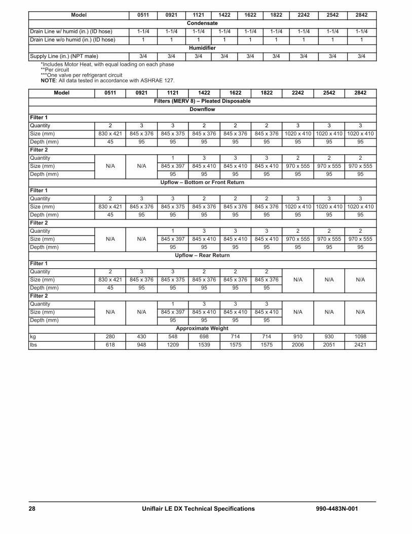
CondensateDrain Line w/ humid (in.) (ID hose)
1-1/4 1-1/4 1-1/4 1-1/4 1-1/4 1-1/4 1-1/4 1-1/4 1-1/4
*Includes Motor Heat, with equal loading on each phase**Per circuitNOTE: All data tested in accordance with ASHRAE 127.
24 Uniflair LE DX Technical Specifications 990-4483N-001

Drain Line w/o humid (in.) (ID hose)
1 1 1 1 1 1 1 1 1
HumidifierSupply Line (in.) (NPT male)
3/4 3/4 3/4 3/4 3/4 3/4 3/4 3/4 3/4
Filters (MERV 8) – Pleated DisposableDownflow
Filter 1Quantity 2 3 3 2 2 2 5 5 5Size (mm) 830 x 421 845 x 376 845 x 376 845 x 376 845 x 376 845 x 376 785 x 486 785 x 486 785 x 486Depth (mm) 45 95 95 95 95 95 95 95 95Filter 2Quantity
N/A N/A1 3 3 3
N/A N/A N/ASize (mm) 845 x 397 845 x 410 845 x 410 845 x 410Depth (mm) 95 95 95 95
Upflow – Bottom or Front ReturnFilter 1Quantity 2 3 3 2 2 2 3 3 3Size (mm) 830 x 421 845 x 376 845 x 375 845 x 376 845 x 376 845 x 376 1020 x 410 1020 x 410 1020 x 410Depth (mm) 45 95 95 95 95 95 95 95 95Filter 2Quantity
N/A N/A1 3 3 3 2 2 2
Size (mm) 845 x 397 845 x 410 845 x 410 845 x 410 970 x 555 970 x 555 970 x 555Depth (mm) 95 95 95 95 95 95 95
Upflow – Rear ReturnFilter 1Quantity 2 3 3 2 2 2 3 3 3Size (mm) 830 x 421 845 x 376 845 x 375 845 x 376 845 x 376 845 x 376 1020 x 410 1020 x 410 1020 x 410Depth (mm) 45 95 95 95 95 95 95 95 95Filter 2Quantity
N/A N/A1 3 3 3 2 2 2
Size (mm) 845 x 397 845 x 410 845 x 410 845 x 410 970 x 555 970 x 555 970 x 555Depth (mm) 95 95 95 95 95 95 95
Approximate Weightkg 280 430 548 698 714 714 910 930 1098lbs 618 948 1209 1539 1575 1575 2006 2051 2421
Model 0511 0921 1121 1422 1622 1822 2242 2542 2842
*Includes Motor Heat, with equal loading on each phase**Per circuitNOTE: All data tested in accordance with ASHRAE 127.
990-4483N-001 Uniflair LE DX Technical Specifications 25

Energy-Saving DX Units (TD/UEV), 40% Propylene GlycolDX mode
Free-cool mode
Model 0511 0921 1121 1422 1622 1822 2242 2542 2842
Net DX Cooling Capacity Data
75°F DB, 61°F WB, 52°F DP (23.9°C DB, 16.1°C WB, 11.1°C DP) 44.6% RH
TotalBTU/Hr 58000 94000 116000 150000 164000 173000 237000 269000 268000
kW 17.0 27.6 34.0 44.0 48.1 50.7 69.6 78.8 78.5
SensibleBTU/Hr 58000 94000 116000 150000 164000 173000 228000 244000 235000
kW 17.0 27.6 34.0 44.0 48.1 50.7 66.7 71.6 68.9
80°F DB, 63°F WB, 52°F DP (26.7°C DB, 17.1°C WB, 11.1°C DP) 37.8% RH
Total BTU/Hr 61000 99000 122000 159000 174000 182000 245000 274000 272000
kW 17.9 28.9 35.7 46.7 50.9 53.3 71.7 80.3 79.7
SensibleBTU/Hr 61000 99000 122000 159000 174000 182000 245000 274000 272000
kW 17.9 28.9 35.7 46.7 50.9 53.3 71.7 80.3 79.7
85°F DB, 64°F WB, 52°F DP (26.7°C DB, 18°C WB, 11.1°C DP) 32.2% RH
Total BTU/Hr 64000 103000 127000 168000 183000 190000 259000 288000 287000
kW 18.7 30.2 37.3 49.3 53.7 55.8 75.8 84.3 84.1
SensibleBTU/Hr 64000 103000 127000 168000 183000 190000 259000 288000 287000
kW 18.7 30.2 37.3 49.3 53.7 55.8 75.8 84.3 84.1
NOTE: All values are accurate to +/– 5% and based on nominal fan speed with standard filterNOTE: Contact the local sales representative for special conditionsNOTE: All data tested in accordance with ASHRAE 127.
Model 0511 0921 1121 1422 1622 1822 2242 2542 2842
Net Cooling Capacity Data
75°F DB, 61°F WB, 52°F DP (23.9°C DB, 16.1°C WB, 11.1°C DP) 44.6% RH
TotalBTU/Hr 35000 50000 70000 104000 104000 110000 245000 245000 245000
kW 10.4 14.6 20.4 30.6 30.6 32.3 71.7 71.8 71.7
SensibleBTU/Hr 35000 50000 70000 104000 104000 110000 244000 245000 244000
kW 10.4 14.6 20.4 30.6 30.6 32.3 71.6 71.7 71.6
80°F DB, 63°F WB, 52°F DP (26.7°C DB, 17.1°C WB, 11.1°C DP) 37.8% RH
Total BTU/Hr 46000 63000 90000 134000 134000 141000 303000 303000 303000
kW 13.4 18.4 26.3 39.2 39.2 41.2 88.8 88.9 88.8
SensibleBTU/Hr 46000 63000 90000 134000 134000 141000 303000 303000 303000
kW 13.4 18.4 26.3 39.2 39.2 41.2 88.7 88.8 88.7
85°F DB, 64°F WB, 52°F DP (26.7°C DB, 18°C WB, 11.1°C DP) 32.2% RH
Total BTU/Hr 56000 76000 109000 162000 162000 170.266 359000 359000 359000
kW 16.3 22.4 32.0 47.5 47.5 49.9 105.1 105.2 105.1
SensibleBTU/Hr 56000 76000 109000 162000 162000 170.266 358000 358000 358000
kW 16.3 22.4 32.0 47.5 47.5 49.9 105.0 105.0 105.0
NOTE: All values are accurate to +/– 5% and based on nominal fan speed with standard filterNOTE: Contact the local sales representative for special conditionsNOTE: All data tested in accordance with ASHRAE 127.
26 Uniflair LE DX Technical Specifications 990-4483N-001

Model 0511 0921 1121 1422 1622 1822 2242 2542 2842Electric Reheat – Staged Aluminum Finned, Low Watt Density
Capacity* (kW @ 460V) 6 12 12 12 12 12 18 18 18Number of Elements 2 4 4 4 4 4 6 6 6Number of Stages 1 3 3 3 3 3 3 3 3Capacity* (kW @ 230V) 6 9 15 15 15 15 18 18 18Number of Elements 2 3 5 5 5 5 6 6 6Number of Stages 1 3 3 3 3 3 3 3 3Capacity* (kW @ 575V) 6 9 15 15 15 15 18 18 18Number of Elements 2 3 5 5 5 5 6 6 6Number of Stages 1 3 3 3 3 3 3 3 3
Hot Water Reheat – 180°F (82.2ºC) EWT, 75°F (24°C) EATCapacity* (BTU/Hr (kW) ) 39800 51200 73600 96900 96900 96900 N/A N/A N/AFlow – GPM 1.0 1.3 1.9 2.2 2.2 2.2 N/A N/A N/APressure Drop (ft H2O) 0.2 0.2 0.3 0.2 0.2 0.2 N/A N/A N/A
Hot Gas Reheat with water 95°F (35°C) LWT, 86°F (30°C) EWT, 75°F (24°C) EATCapacity* (BTU/Hr) 32900 43800 60500 39300 40200 40800 N/A N/A N/A
Humidification – Steam Canister Immersed Electrode Capacity (kg/Hr) 5 8 8 8 8 8 8 8 8Power Input (kW) 3.7 6.0 6.0 6.0 6.0 6.0 6.0 6.0 6.0Flush Cycle Auto. Auto. Auto. Auto. Auto. Auto. Auto. Auto. Auto.
Evaporator Blower/Motor – Direct Drive Electronic Commutation (EC) Backward Curved FansNominal Horsepower 3.8 4.0 4.0 4.0 4.0 4.0 4.0 4.0 4.0CFM @ .20 in. WC ESP 3500 4800 7100 9200 9300 9300 12600 12600 12600Quantity 1 1 2 2 2 2 3 3 3
Evaporator/Free Cooling Coil – INTERLACED, Slab, Copper Tube/Aluminum Fin, Hydrophilic CoatedFace Area (ft2) 7.5 9.7 14.0 17.2 17.2 17.2 24.8 24.8 24.8Rows 3 3 3 3 3 3 4 4 5Face Velocity (FPM) 467 495 507 535 541 541 508 508 508
Compressors – Tandem Scroll – R-410A (75°F (24°C) RAT / 50% RH)Quantity 1 2 2 2 2 2 4 4 4Power Input (Watts) 4800 7500 9700 10200 12100 14300 18800 28900 21200
Water Cooled Condenser Data – 40% GlycolFlow (GPM @ 105°F (41ºC) EWT / 115°F (46ºC) LWT)
17.2 27.5 34.8 43.1 48.2 52.3 76.2 81.8 85.8
Brazed Plate Pressure Drop(ft. of H2O)
5.6 5.2 5.6 3.3 4.0 4.8 17.7 9.4 15.4
Valve Pressure Drop (ft. of H2O)** 3.7 4.6 7.3 2.8 3.5 4.1 8.8 10.1 11.2Econ Coil Pressure Drop(ft. of H2O)
6.2 5.6 8.1 6.2 8.5 5.1 9.2 9.2 9.2
Flow (GPM @ 110° F(43ºC) EWT / 120°F (49ºC) LWT)
16.7 26.6 33.7 41.6 46.3 50.7 73.1 79.3 83.4
Brazed Plate Pressure Drop(ft. of H2O)
5.2 4.9 5.2 3.1 3.8 4.4 16.2 18.8 14.5
Valve Pressure Drop (ft. of H2O)** 3.5 4.3 6.9 2.6 3.3 3.9 8.1 9.5 10.5Econ Coil Pressure Drop (ft. of H2O) 6.2 5.6 8.1 6.2 8.5 5.1 9.2 9.2 9.2Water Circuit Capacity(liters (gallons))
5 (1.3) 12 (3.2) 14 (3.7) 17 (4.5) 17 (4.5) 17 (4.5) 22 (5.8) 22 (5.8) 22 (5.8)
Connection Sizes (not recommended piping sizes)Condenser In/Out (in.) (OD) 1-1/8 1-3/8 1-3/8 1-5/8 1-5/8 1-5/8 1-5/8 1-5/8 1-5/8
Hot Water ReheatSupply Line (in.) (OD) 7/8 7/8 7/8 1-1/8 1-1/8 1-1/8 – – –Return Line (in.) (OD) 7/8 7/8 7/8 1-1/8 1-1/8 1-1/8 – – –
*Includes Motor Heat, with equal loading on each phase**Per circuit***One valve per refrigerant circuitNOTE: All data tested in accordance with ASHRAE 127.
990-4483N-001 Uniflair LE DX Technical Specifications 27
CondensateDrain Line w/ humid (in.) (ID hose) 1-1/4 1-1/4 1-1/4 1-1/4 1-1/4 1-1/4 1-1/4 1-1/4 1-1/4Drain Line w/o humid (in.) (ID hose) 1 1 1 1 1 1 1 1 1
HumidifierSupply Line (in.) (NPT male) 3/4 3/4 3/4 3/4 3/4 3/4 3/4 3/4 3/4
Model 0511 0921 1121 1422 1622 1822 2242 2542 2842Filters (MERV 8) – Pleated Disposable
DownflowFilter 1Quantity 2 3 3 2 2 2 3 3 3Size (mm) 830 x 421 845 x 376 845 x 375 845 x 376 845 x 376 845 x 376 1020 x 410 1020 x 410 1020 x 410Depth (mm) 45 95 95 95 95 95 95 95 95Filter 2Quantity
N/A N/A1 3 3 3 2 2 2
Size (mm) 845 x 397 845 x 410 845 x 410 845 x 410 970 x 555 970 x 555 970 x 555Depth (mm) 95 95 95 95 95 95 95
Upflow – Bottom or Front ReturnFilter 1Quantity 2 3 3 2 2 2 3 3 3Size (mm) 830 x 421 845 x 376 845 x 375 845 x 376 845 x 376 845 x 376 1020 x 410 1020 x 410 1020 x 410Depth (mm) 45 95 95 95 95 95 95 95 95Filter 2Quantity
N/A N/A1 3 3 3 2 2 2
Size (mm) 845 x 397 845 x 410 845 x 410 845 x 410 970 x 555 970 x 555 970 x 555Depth (mm) 95 95 95 95 95 95 95
Upflow – Rear ReturnFilter 1Quantity 2 3 3 2 2 2
N/A N/A N/ASize (mm) 830 x 421 845 x 376 845 x 375 845 x 376 845 x 376 845 x 376Depth (mm) 45 95 95 95 95 95Filter 2Quantity
N/A N/A1 3 3 3
N/A N/A N/ASize (mm) 845 x 397 845 x 410 845 x 410 845 x 410Depth (mm) 95 95 95 95
Approximate Weightkg 280 430 548 698 714 714 910 930 1098lbs 618 948 1209 1539 1575 1575 2006 2051 2421
Model 0511 0921 1121 1422 1622 1822 2242 2542 2842
*Includes Motor Heat, with equal loading on each phase**Per circuit***One valve per refrigerant circuitNOTE: All data tested in accordance with ASHRAE 127.
28 Uniflair LE DX Technical Specifications 990-4483N-001

Glycol correction factors
Values are derived using the Darcy-Weisbach pressure drop equation at 50°F and 1 atmosphere and Type L copper pipe.All correction factors are based on the unit entering the following conditions:29.4°C (85°F) DB/18.1°C (64.5°F) WB,2832 l/s (6000 CFM), 1.72 l/s (27.3 GPM), and 7.2°C (45°F) EFT.*Multiply capacity of device or system by factor above for % solution.**Multiply pressure drop of system by factor above for % solution.***Glycol concentrations over 50% are not recommended.
Values are derived using the Darcy-Weisbach pressure drop equation at 50°F and 1 atmosphere and Type L copper pipe.All correction factors are based on the unit entering the following conditions:29.4°C (85°F) DB/18.1°C (64.5°F) WB,2832 l/s (6000 CFM), 1.72 l/s (27.3 GPM), and 7.2°C (45°F) EFT.*Multiply capacity of device or system by factor above for % solution.**Multiply pressure drop of system by factor above for % solution.***Glycol concentrations over 50% are not recommended.
Performance Criteria
Glycol Solution
Percent Volume of Solution ***
0 10% 20% 30% 40% 50%
Capacity*Ethylene 1.00 0.96 0.94 0.91 0.87 0.84
Propylene 1.00 0.98 0.97 0.94 0.91 0.88
Pressure Drop**Ethylene 1.00 1.04 1.14 1.24 1.36 1.50
Propylene 1.00 1.10 1.23 1.43 1.67 1.92
Performance Criteria
Glycol Solution
Percent Mass of Solution ***
0 10% 20% 30% 40% 50%
Capacity*Ethylene 1.00 0.96 0.94 0.91 0.87 0.84
Propylene 1.00 0.98 0.97 0.94 0.91 0.88
Pressure Drop**Ethylene 1.00 1.01 1.08 1.14 1.23 1.32
Propylene 1.00 1.08 1.18 1.35 1.56 1.77
990-4483N-001 Uniflair LE DX Technical Specifications 29

Sound DataSound pressure measurement positioning
na33
83a
1 m (3.28 ft)
2 m (6.56 ft)
30 Uniflair LE DX Technical Specifications 990-4483N-001
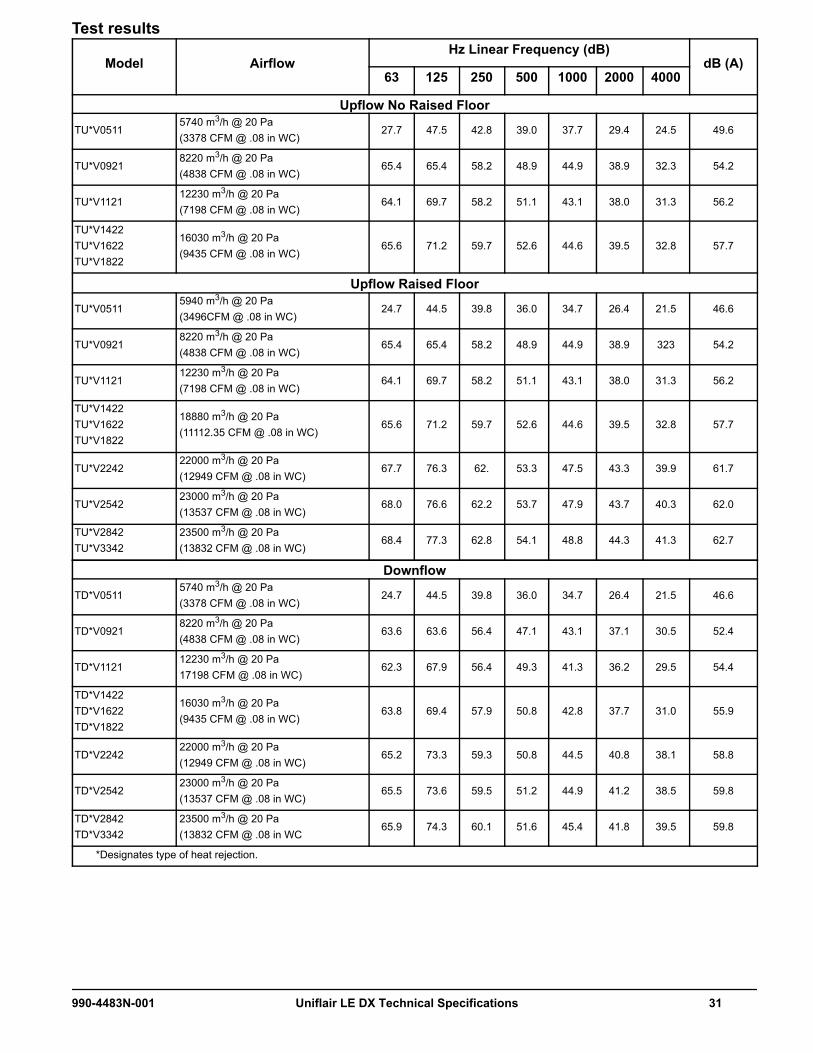
Test results
Model AirflowHz Linear Frequency (dB)
dB (A)63 125 250 500 1000 2000 4000
Upflow No Raised Floor
TU*V05115740 m3/h @ 20 Pa(3378 CFM @ .08 in WC)
27.7 47.5 42.8 39.0 37.7 29.4 24.5 49.6
TU*V09218220 m3/h @ 20 Pa(4838 CFM @ .08 in WC)
65.4 65.4 58.2 48.9 44.9 38.9 32.3 54.2
TU*V112112230 m3/h @ 20 Pa(7198 CFM @ .08 in WC)
64.1 69.7 58.2 51.1 43.1 38.0 31.3 56.2
TU*V1422TU*V1622TU*V1822
16030 m3/h @ 20 Pa(9435 CFM @ .08 in WC)
65.6 71.2 59.7 52.6 44.6 39.5 32.8 57.7
Upflow Raised Floor
TU*V05115940 m3/h @ 20 Pa(3496CFM @ .08 in WC)
24.7 44.5 39.8 36.0 34.7 26.4 21.5 46.6
TU*V09218220 m3/h @ 20 Pa(4838 CFM @ .08 in WC)
65.4 65.4 58.2 48.9 44.9 38.9 323 54.2
TU*V112112230 m3/h @ 20 Pa(7198 CFM @ .08 in WC)
64.1 69.7 58.2 51.1 43.1 38.0 31.3 56.2
TU*V1422TU*V1622TU*V1822
18880 m3/h @ 20 Pa(11112.35 CFM @ .08 in WC)
65.6 71.2 59.7 52.6 44.6 39.5 32.8 57.7
TU*V224222000 m3/h @ 20 Pa(12949 CFM @ .08 in WC)
67.7 76.3 62. 53.3 47.5 43.3 39.9 61.7
TU*V254223000 m3/h @ 20 Pa(13537 CFM @ .08 in WC)
68.0 76.6 62.2 53.7 47.9 43.7 40.3 62.0
TU*V2842TU*V3342
23500 m3/h @ 20 Pa(13832 CFM @ .08 in WC)
68.4 77.3 62.8 54.1 48.8 44.3 41.3 62.7
Downflow
TD*V05115740 m3/h @ 20 Pa(3378 CFM @ .08 in WC)
24.7 44.5 39.8 36.0 34.7 26.4 21.5 46.6
TD*V09218220 m3/h @ 20 Pa(4838 CFM @ .08 in WC)
63.6 63.6 56.4 47.1 43.1 37.1 30.5 52.4
TD*V112112230 m3/h @ 20 Pa17198 CFM @ .08 in WC)
62.3 67.9 56.4 49.3 41.3 36.2 29.5 54.4
TD*V1422TD*V1622TD*V1822
16030 m3/h @ 20 Pa(9435 CFM @ .08 in WC)
63.8 69.4 57.9 50.8 42.8 37.7 31.0 55.9
TD*V224222000 m3/h @ 20 Pa(12949 CFM @ .08 in WC)
65.2 73.3 59.3 50.8 44.5 40.8 38.1 58.8
TD*V254223000 m3/h @ 20 Pa(13537 CFM @ .08 in WC)
65.5 73.6 59.5 51.2 44.9 41.2 38.5 59.8
TD*V2842TD*V3342
23500 m3/h @ 20 Pa(13832 CFM @ .08 in WC
65.9 74.3 60.1 51.6 45.4 41.8 39.5 59.8
*Designates type of heat rejection.
990-4483N-001 Uniflair LE DX Technical Specifications 31

Electrical SpecificationsNOTE: 5 kA SCCR is standard for all units; 65 kA SCCR options are available. SCCR is the maximum short circuit a component, assembly, or equipment can safely withstand when protected by a specific overcurrent protective device or for a specified time interval.
DX Models With Condensate PumpReheat Option Electric Reheat None Electric Reheat None
Humidifier Option
Humidifier Humidifier None None
Model Voltage FLA MCA MOP FLA MCA MOP FLA MCA MOP FLA MCA MOP
0511
208 42.6 54.2 70 39.4 47.6 60 42.6 54.2 70 29.0 37.2 50
230 43.8 55.8 70 38.2 46.4 60 43.8 55.8 70 28.8 37.0 50
460 27.2 34.9 40 18.8 23.3 30 27.2 34.9 40 14.1 18.6 25
575 18.3 20.6 25 16.1 16.8 20 18.3 20.6 25 12.3 13.1 20
0921
208 60.3 78.5 90 56.5 69.6 80 59.8 78.0 80 39.4 52.4 60
230 62.1 80.8 90 54.6 67.6 80 61.7 80.4 90 39.1 52.1 60
460 40.1 54.9 60 25.1 34.2 40 39.9 54.7 60 17.3 26.4 35
575 24.8 31.3 35 21.8 26.0 30 24.6 30.2 35 15.6 18.9 25
1121
208 90.1 110.3 125 72.7 84.4 100 89.7 109.8 110 55.6 67.3 80
230 93.4 114.4 125 70.8 82.4 100 93.0 114.0 125 55.3 66.9 80
460 49.8 61.9 70 34.7 41.2 50 49.6 61.7 70 27.0 33.5 40
575 38.8 44.9 45 29.8 32.1 35 38.6 43.8 45 23.6 25.0 30
1422
208 80.5 95.1 110 80.5 91.6 110 78.0 94.6 100 63.4 74.5 90
230 81.7 99.2 110 78.6 89.6 110 81.3 98.8 110 63.1 74.1 90
460 43.7 55.6 60 37.4 47.1 50 43.5 55.4 60 29.6 39.3 50
575 32.1 39.6 45 30.1 36.3 45 31.9 38.5 40 23.9 29.3 35
1622
208 86.0 99.7 125 86.0 99.7 125 80.8 99.1 110 68.8 82.6 100
230 84.6 103.7 110 84.1 97.7 110 84.1 103.3 110 68.6 82.2 100
460 45.1 56.6 60 40.1 48.9 60 44.9 56.4 60 32.4 41.1 50
575 32.9 39.2 45 31.7 35.7 45 32.7 38.1 40 25.5 28.6 35
1822
208 88.7 101.1 125 88.7 101.1 125 82.2 99.9 110 71.6 83.9 110
230 86.8 104.5 125 86.8 99.1 125 85.5 104.1 110 71.3 83.6 110
460 46.7 55.6 60 43.3 47.1 50 46.5 55.4 60 35.6 39.3 50
575 36.4 41.2 50 36.4 39.3 50 35.0 40.1 45 30.2 32.2 40
32 Uniflair LE DX Technical Specifications 990-4483N-001

2242
208 113.5 132.0 150 113.5 132.0 150 106.1 127.5 150 96.3 114.9 125
230 111.6 133.1 150 111.6 130.0 150 110.1 132.6 150 96.1 114.5 125
460 54.9 66.7 70 54.6 65.2 70 54.7 66.5 70 46.9 57.5 60
575 47.7 52.5 60 47.7 51.3 60 45.7 51.4 60 41.5 44.2 50
2542
208 117.9 148.2 150 117.9 148.2 150 108.3 136.1 150 100.7 131.0 150
230 116.0 146.2 150 116.0 146.2 150 112.3 141.2 150 100.5 130.7 150
460 58.4 76.3 80 58.4 76.3 80 56.6 72.4 80 50.7 68.5 80
575 46.8 55.1 60 46.8 55.1 60 45.3 53.5 60 40.6 48.1 50
2842
208 129.0 145.6 150 129.0 145.6 150 113.8 134.7 150 111.9 128.5 150
230 127.1 143.6 150 127.1 143.6 150 117.9 139.8 150 111.7 128.1 150
460 59.9 76.3 80 59.9 76.3 80 57.3 72.4 80 52.2 68.5 80
575 48.3 59.4 60 48.3 59.4 60 46.1 55.7 60 42.1 52.3 60
3342
208 139.9 162.3 175 139.9 162.3 175 122.8 145.1 150 122.8 145.1 150
230 138.1 160.5 175 138.1 160.5 175 123.6 149.4 150 122.6 145.0 150
460 65.4 79.7 90 65.4 79.7 90 60.1 74.2 80 57.7 71.9 80
575 51.6 58.1 60 51.6 58.1 60 47.7 55.0 60 45.4 51.0 60
Reheat Option Electric Reheat None Electric Reheat None
Humidifier Option
Humidifier Humidifier None None
Model Voltage FLA MCA MOP FLA MCA MOP FLA MCA MOP FLA MCA MOP
990-4483N-001 Uniflair LE DX Technical Specifications 33

DX Models Without Condensate PumpReheat Option Electric Reheat None Electric Reheat None
Humidifier Option
Humidifier Humidifier None None
Model Voltage FLA MCA MOP FLA MCA MOP FLA MCA MOP FLA MCA MOP
0511
208 40.3 51.9 60 37.1 45.3 60 40.3 51.9 60 26.7 34.9 50
230 41.5 53.5 60 35.9 44.1 60 41.5 53.5 60 26.5 34.7 50
460 26.0 33.7 40 17.6 22.1 30 26.0 33.7 40 12.9 17.4 25
575 17.4 20.6 25 15.1 16.8 20 17.4 20.6 25 11.3 13.1 20
0921
208 58.0 76.2 80 54.2 67.3 80 57.5 75.7 80 37.1 50.1 60
230 59.8 78.5 80 52.3 65.3 80 59.4 78.1 80 36.8 49.8 60
460 38.9 53.7 60 23.9 33.0 40 38.7 53.5 60 16.1 25.2 30
575 23.8 31.3 35 20.8 26.0 30 23.6 30.2 35 14.6 18.9 25
1121
208 87.8 108.0 110 70.4 82.1 100 87.4 107.5 110 53.3 65.0 80
230 91.1 112.1 125 68.5 80.1 90 90.7 111.7 125 53.0 64.6 80
460 48.6 60.7 70 33.5 40.0 45 48.4 60.5 70 25.8 32.3 40
575 37.8 44.9 45 28.8 32.1 35 37.7 43.8 45 22.6 25.0 30
1422
208 78.2 92.8 110 78.2 89.3 110 75.7 92.3 100 61.1 72.2 90
230 79.4 96.9 100 76.3 87.3 100 79.0 96.5 100 60.8 71.8 90
460 42.5 54.4 60 36.2 45.9 50 42.3 54.2 60 28.4 38.1 50
575 31.1 39.6 45 29.1 36.3 45 30.9 38.5 40 22.9 29.3 35
1622
208 83.7 97.4 110 83.7 97.4 110 78.5 96.8 110 66.5 80.3 100
230 82.3 101.4 110 81.8 95.4 110 81.8 101.0 110 66.3 79.9 100
460 43.9 55.4 60 38.9 47.7 60 43.7 55.2 60 31.2 39.9 50
575 31.9 39.2 45 30.8 35.7 45 31.7 38.1 40 24.6 28.6 35
1822
208 86.4 98.8 125 86.4 98.8 125 79.9 97.6 110 69.3 81.6 100
230 84.5 102.2 110 84.5 96.8 110 83.2 101.8 110 69.0 81.3 100
460 45.5 54.4 60 42.1 45.9 50 45.3 54.2 60 34.4 38.1 50
575 35.5 41.2 50 35.5 39.3 50 34.1 40.1 45 29.3 32.2 40
2242
208 111.2 129.7 150 111.2 129.7 150 103.8 125.2 150 94.0 112.6 125
230 109.3 130.8 150 109.3 127.7 150 107.8 130.3 150 93.8 112.2 125
460 53.7 65.5 70 53.4 64.0 70 53.5 65.3 70 45.7 56.3 60
575 46.7 52.5 60 46.7 51.3 60 44.8 51.4 60 40.5 44.2 50
2542
208 115.6 145.9 150 115.6 145.9 150 106.0 133.8 150 98.4 128.7 150
230 113.7 143.9 150 113.7 143.9 150 110.0 138.9 150 98.2 128.4 150
460 57.2 75.1 80 57.2 75.1 80 55.4 71.2 80 49.5 67.3 70
575 45.9 55.1 60 45.9 55.1 60 44.4 53.5 60 39.7 48.1 50
34 Uniflair LE DX Technical Specifications 990-4483N-001

2842
208 126.7 143.3 150 126.7 143.3 150 111.5 132.4 150 109.6 126.2 150
230 124.8 141.3 150 124.8 141.3 150 115.6 137.5 150 109.4 125.8 150
460 58.7 75.1 80 58.7 75.1 80 56.1 71.2 80 51.0 67.3 70
575 47.4 59.4 60 47.4 59.4 60 45.1 55.7 60 41.2 52.3 60
3342
208 137.6 160.0 175 137.6 160.0 175 120.5 142.8 150 120.5 142.8 150
230 135.8 158.2 175 135.8 158.2 175 121.3 147.1 150 120.3 142.7 150
460 64.2 78.5 90 64.2 78.5 90 58.9 73.0 80 56.5 70.7 80
575 50.6 58.1 60 50.6 58.1 60 46.7 55.0 60 44.4 51.0 60
Reheat Option Electric Reheat None Electric Reheat None
Humidifier Option
Humidifier Humidifier None None
Model Voltage FLA MCA MOP FLA MCA MOP FLA MCA MOP FLA MCA MOP
990-4483N-001 Uniflair LE DX Technical Specifications 35

Dimensional DataOverall Unit
*TD/UAV511Note: Motorized damper option adds 152 mm (6 in.) in height.
Frame Size
Model AirflowDimensions mm (in.) Net Weight
kg (lb)A B C
3 0511
Upflow and Downflow
1960 (77.17) 1010 (39.76) 750 (29.53)280 (617)430 (948)*
4 0921 1960 (77.17) 1310 (51.57) 865 (34.06) 430 (948)5 1121 1960 (77.17) 1720 (67.72) 865 (34.06) 548 (1208)
61422 1960 (77.17) 2159 (85.00) 865 (34.06) 698 (1539)1622 1960 (77.17) 2159 (85.00) 865 (34.06)
714 (1574)1822 1960 (77.17) 2159 (85.00) 865 (34.06)
7
2242Upflow 1960 (77.17)
2580 (101.57) 865 (34.06) 910 (2006)Downflow 2175 (85.63)
2542Upflow 1960 (77.17)
2580 (101.57) 865 (34.06) 930 (2050)Downflow 2175 (85.63)
2842Upflow 1960 (77.17)
2580 (101.57) 865 (34.06)1098 (2421)
Downflow 2175 (85.63)
3342Upflow 1960 (77.17)
2580 (101.57) 865 (34.06)Downflow 2175 (85.63)
B
A
C
914.4 mm (36 in.)SERVICE CLEARANCE
(ONLY FRONT ACCESS NEEDED)
36 Uniflair LE DX Technical Specifications 990-4483N-001

Plenums/Sub-BasesFor upflow installations where piping and wiring connections are not coming up from the bottom, a sub-base is required to access piping and electrical connections.
Type of Plenum Model Color Frame SizeDimensions mm (in.) Net Weight
kg (lb)A B C
Top discharge or return plenum
500 mm (20 in.)
ACPL75110ACPL75130ACPL75131ACPL75132
BlueWhiteGrayBlack
3500
(19.69)1010
(39.76)750
(29.53)37.00
(81.57)
ACPL75111ACPL75133ACPL75134ACPL75135
BlueWhiteGrayBlack
4500
(19.69)1310
(51.57)865
(34.06)45.00
(99.21)
ACPL75112ACPL75136ACPL75137ACPL75138
BlueWhiteGrayBlack
5500
(19.69)1720
(67.72)865
(34.06)53.50
(117.95)
ACPL75113ACPL75139ACPL75140ACPL75141
BlueWhiteGrayBlack
6500
(19.69)2170
(85.43)865
(34.06)62.00
(136.70)
ACPL75114ACPL75142ACPL75143ACPL75144
BlueWhiteGrayBlack
7500
(19.69)2582
(101.65)865
(34.06)70.00
(154.30)
C
A
B C
A
B
A
BC
A
BC
C
A
B C
A
B
na36
69a
TOP AIR DISCHARGE PLENUM 500 mm (20 in.)
SUB-BASE 500 mm (20 in.) FRONT DISCHARGE
SUB-BASE 200 mm (8 in.)
TOP AIR DISCHARGE PLENUM 305 mm (12 in.)* SUB-BASE 500 mm (20 in.) NO GRILLE
FRONT DISCHARGE PLENUM 500 mm (20 in.)
*Stackable up to 1220 mm (48 in.)
990-4483N-001 Uniflair LE DX Technical Specifications 37
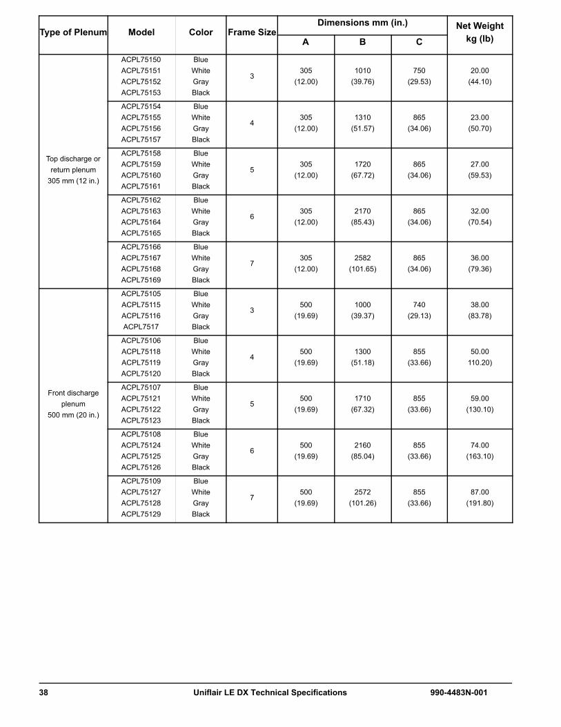
Top discharge or return plenum
305 mm (12 in.)
ACPL75150ACPL75151ACPL75152ACPL75153
BlueWhiteGrayBlack
3305
(12.00)1010
(39.76)750
(29.53)20.00
(44.10)
ACPL75154ACPL75155ACPL75156ACPL75157
BlueWhiteGrayBlack
4305
(12.00)1310
(51.57)865
(34.06)23.00
(50.70)
ACPL75158ACPL75159ACPL75160ACPL75161
BlueWhiteGrayBlack
5305
(12.00)1720
(67.72)865
(34.06)27.00
(59.53)
ACPL75162ACPL75163ACPL75164ACPL75165
BlueWhiteGrayBlack
6305
(12.00)2170
(85.43)865
(34.06)32.00
(70.54)
ACPL75166ACPL75167ACPL75168ACPL75169
BlueWhiteGrayBlack
7305
(12.00)2582
(101.65)865
(34.06)36.00
(79.36)
Front discharge plenum
500 mm (20 in.)
ACPL75105ACPL75115ACPL75116ACPL7517
BlueWhiteGrayBlack
3500
(19.69)1000
(39.37)740
(29.13)38.00
(83.78)
ACPL75106ACPL75118ACPL75119ACPL75120
BlueWhiteGrayBlack
4500
(19.69)1300
(51.18)855
(33.66)50.00
110.20)
ACPL75107 ACPL75121ACPL75122ACPL75123
BlueWhiteGrayBlack
5500
(19.69)1710
(67.32)855
(33.66)59.00
(130.10)
ACPL75108ACPL75124ACPL75125ACPL75126
BlueWhiteGrayBlack
6500
(19.69)2160
(85.04)855
(33.66)74.00
(163.10)
ACPL75109ACPL75127ACPL75128ACPL75129
BlueWhiteGrayBlack
7500
(19.69)2572
(101.26)855
(33.66)87.00
(191.80)
Type of Plenum Model Color Frame SizeDimensions mm (in.) Net Weight
kg (lb)A B C
38 Uniflair LE DX Technical Specifications 990-4483N-001

Sub-base 200 mm (8 in.)
ACSB76140ACSB76150ACSB76151ACSB76152
BlueWhiteGrayBlack
3200
(7.87)1000
(39.37)740
(29.13)17.70
(39.02)
ACSB76141ACSB76153ACSB76154ACSB76155
BlueWhiteGrayBlack
4200
(7.87)1300
(51.18)855
(33.66)21.80
(48.06)
ACSB76142ACSB76156ACSB76157ACSB76158
BlueWhiteGrayBlack
5200
(7.87)1710
(67.32)855
(33.66)27.20
(59.97)
ACSB76143ACSB76159ACSB76160ACSB76161
BlueWhiteGrayBlack
6200
(7.87)2160
(85.04)855
(33.66)31.60
(69.67)
ACSB76144ACSB76162ACSB76163ACSB76164
BlueWhiteGrayBlack
7200
(7.87)2572
(101.26)855
(33.66)35.60
(74.49)
Sub-base 500 mm (20 in.)
no grille
ACSB76180ACSB76181ACSB76182ACSB76183
BlueWhiteGrayBlack
3500
(19.69)1000
(39.37)740
(29.13)41.00
(90.38)
ACSB76184ACSB76185ACSB76186ACSB76167
BlueWhiteGrayBlack
4500
(19.69)1300
(51.18)855
(33.66)53.00
(116.86)
ACSB76188ACSB76189ACSB76190ACSB76191
BlueWhiteGrayBlack
5500
(19.69)1710
(67.32)855
(33.66)62.00
(136.69)
ACSB76192ACSB76193ACSB76194ACSB76195
BlueWhiteGrayBlack
6500
(19.69)2160
(85.04)855
(33.6677.00
(169.76)
ACSB76196ACSB76197ACSB76198ACSB76199
BlueWhiteGrayBlack
7500
(19.69)2572
(101.26)855
(33.66)90.00
(198.42)
Type of Plenum Model Color Frame SizeDimensions mm (in.) Net Weight
kg (lb)A B C
990-4483N-001 Uniflair LE DX Technical Specifications 39

Sub-base 500 mm (20 in.) front discharge
ACSB76145ACSB76165ACSB76166ACSB76167
BlueWhiteGrayBlack
3500
(19.69)1000
(39.37)740
(29.13)38.00
(183.78)
ACSB76146ACSB76168ACSB76169ACSB76170
BlueWhiteGrayBlack
4500
(19.69)1300
(51.18)855
(33.66)50.00
(110.20)
ACSB76147 ACSB76171ACSB76172ACSB76173
BlueWhiteGrayBlack
5500
(19.69)1710
(67.32)855
(33.66)59.00
(130.10)
ACSB76148ACSB76174ACSB76175ACSB76176
BlueWhiteGrayBlack
6500
(19.69)2160
(85.04)855
(33.6674.00
(163.10)
ACSB76149ACSB76177ACSB76178ACSB76179
BlueWhiteGrayBlack
7500
(19.69)2572
(101.26)855
(33.66)87.00
(191.80)
Type of Plenum Model Color Frame SizeDimensions mm (in.) Net Weight
kg (lb)A B C
40 Uniflair LE DX Technical Specifications 990-4483N-001

Fixed Floor Stands
NOTE: Rubber, vibration isolation pads are field supplied
ModelFrame Size
Weightkg (lb)
Dimensions mm (in.)
A B C D EACFS76084ACFS76089ACFS76094ACFS76055
3
25 (54)26 (58)28 (61)
25.8 (56.9)
305 (12)457 (18)610 (24)914 (36)
1000(39.37)
740(29.13)
1077(42.40)
817(32.17)
ACFS76085ACFS76090ACFS76095ACFS76056
4
35 (77)37 (82)40 (87)
36.5 (80.4)
305 (12)457 (18)610 (24)914 (36)
1300(51.18)
855(33.66)
1377(54.21)
932(36.73)
ACFS76086ACFS76091ACFS76096ACFS76057
5
39 (86)41 (90)43 (95)
40.0 (88.8)
305 (12)457 (18)610 (24)914 (36)
1710(67.32)
855(33.66)
1786(70.35)
932(36.73)
ACFS76087ACFS76092ACFS76097ACFS76058
6
48 (105)50 (111)53 (117)
49.6 (109.1)
305 (12)457 (18)610 (24)914 (36)
2160(85.04)
855(33.66)
2221(88.11)
932(36.73)
ACFS76088ACFS76093ACFS76098ACFS76059
7
51 (113)55 (120)57 (126)
53.5 (117.6)
305 (12)457 (18)610 (24)914 (36)
2572(101.26)
855(33.66)
2631(104.25)
932(36.73)
C* B*
A
C* B*
A
C* B*
A
C*
A
B*C*
A
B*
na37
13a
E**
D**
990-4483N-001 Uniflair LE DX Technical Specifications 41

Seismic Floorstands
NOTE: Rubber, vibration isolation pads are field supplied.
ModelFrame Size
Weightkg (lb)
Dimensions mm (in.)
A B C D EACFS76060ACFS76065ACFS76070ACFS76075
3
27.3 (60.2)29.6 (65.3)31.8 (70.1)34.1 (75.2)
305 (12)457 (18)610 (24)914 (36)
1000(39.37)
740(29.13)
1060(41.73)
800(31.50)
ACFS76061ACFS76066ACFS76071ACFS76076
4
38.6 (80.1)40.9 (90.2)43.2 (95.2)
45.5 (100.3)
305 (12)457 (18)610 (24)914 (36)
1300(51.18)
855(33.66)
1360(53.54)
916(36.06)
ACFS76062ACFS76067ACFS76072ACFS76077
5
43.1 (95.0)45.5 (100.3)47.7 (105.2)50.0 (110.2)
305 (12)457 (18)610 (24)914 (36)
1710(67.32)
855(33.66)
1770(69.69)
916(36.06)
ACFS76063ACFS76068ACFS76073ACFS76078
6
52.3 (115.3)54.5 (120.2)56.8 (125.2)59.1 (130.3)
305 (12)457 (18)610 (24)914 (36)
2160(85.04)
855(33.66)
2221(87.44)
916(36.06)
ACFS76064ACFS76069ACFS76074ACFS76079
7
56.8 (125.2)56.8 (125.2)61.4 (135.4)63.6 (140.2)
305 (12)457 (18)610 (24)914 (36)
2572(101.26)
855(33.66)
2631(103.58)
916(36.06)
na39
40a
E
D
B
A
C
A
BC
A
CB
42 Uniflair LE DX Technical Specifications 990-4483N-001
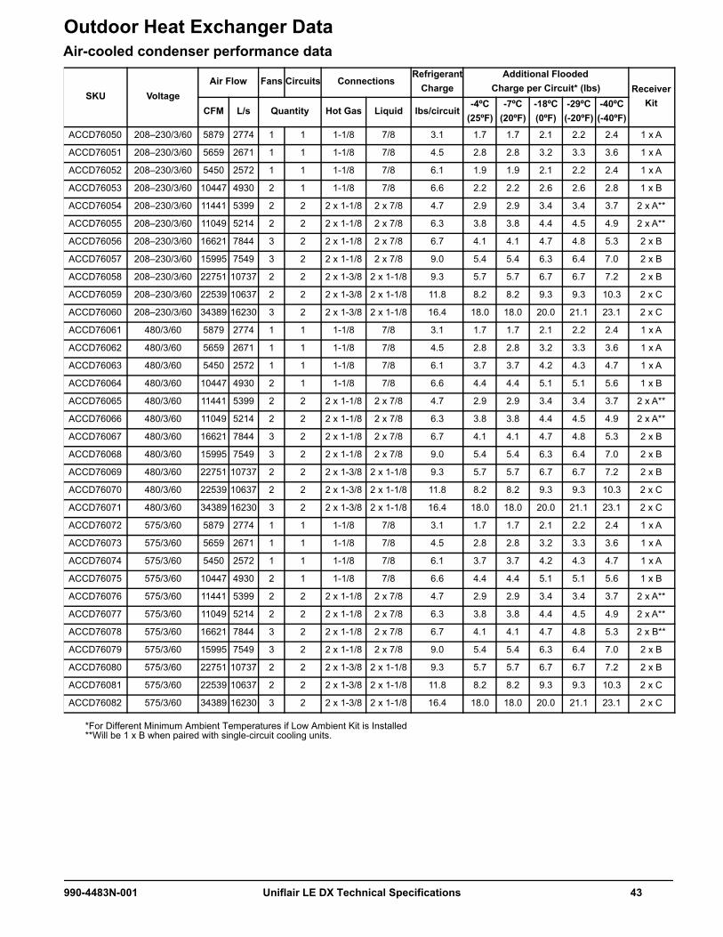
Outdoor Heat Exchanger DataAir-cooled condenser performance data
SKU VoltageAir Flow Fans Circuits Connections
Refrigerant Charge
Additional Flooded Charge per Circuit* (lbs) Receiver
KitCFM L/s Quantity Hot Gas Liquid lbs/circuit
-4ºC(25ºF)
-7ºC (20ºF)
-18ºC(0ºF)
-29ºC (-20ºF)
-40ºC(-40ºF)
ACCD76050 208–230/3/60 5879 2774 1 1 1-1/8 7/8 3.1 1.7 1.7 2.1 2.2 2.4 1 x A
ACCD76051 208–230/3/60 5659 2671 1 1 1-1/8 7/8 4.5 2.8 2.8 3.2 3.3 3.6 1 x A
ACCD76052 208–230/3/60 5450 2572 1 1 1-1/8 7/8 6.1 1.9 1.9 2.1 2.2 2.4 1 x A
ACCD76053 208–230/3/60 10447 4930 2 1 1-1/8 7/8 6.6 2.2 2.2 2.6 2.6 2.8 1 x B
ACCD76054 208–230/3/60 11441 5399 2 2 2 x 1-1/8 2 x 7/8 4.7 2.9 2.9 3.4 3.4 3.7 2 x A**
ACCD76055 208–230/3/60 11049 5214 2 2 2 x 1-1/8 2 x 7/8 6.3 3.8 3.8 4.4 4.5 4.9 2 x A**
ACCD76056 208–230/3/60 16621 7844 3 2 2 x 1-1/8 2 x 7/8 6.7 4.1 4.1 4.7 4.8 5.3 2 x B
ACCD76057 208–230/3/60 15995 7549 3 2 2 x 1-1/8 2 x 7/8 9.0 5.4 5.4 6.3 6.4 7.0 2 x B
ACCD76058 208–230/3/60 22751 10737 2 2 2 x 1-3/8 2 x 1-1/8 9.3 5.7 5.7 6.7 6.7 7.2 2 x B
ACCD76059 208–230/3/60 22539 10637 2 2 2 x 1-3/8 2 x 1-1/8 11.8 8.2 8.2 9.3 9.3 10.3 2 x C
ACCD76060 208–230/3/60 34389 16230 3 2 2 x 1-3/8 2 x 1-1/8 16.4 18.0 18.0 20.0 21.1 23.1 2 x C
ACCD76061 480/3/60 5879 2774 1 1 1-1/8 7/8 3.1 1.7 1.7 2.1 2.2 2.4 1 x A
ACCD76062 480/3/60 5659 2671 1 1 1-1/8 7/8 4.5 2.8 2.8 3.2 3.3 3.6 1 x A
ACCD76063 480/3/60 5450 2572 1 1 1-1/8 7/8 6.1 3.7 3.7 4.2 4.3 4.7 1 x A
ACCD76064 480/3/60 10447 4930 2 1 1-1/8 7/8 6.6 4.4 4.4 5.1 5.1 5.6 1 x B
ACCD76065 480/3/60 11441 5399 2 2 2 x 1-1/8 2 x 7/8 4.7 2.9 2.9 3.4 3.4 3.7 2 x A**
ACCD76066 480/3/60 11049 5214 2 2 2 x 1-1/8 2 x 7/8 6.3 3.8 3.8 4.4 4.5 4.9 2 x A**
ACCD76067 480/3/60 16621 7844 3 2 2 x 1-1/8 2 x 7/8 6.7 4.1 4.1 4.7 4.8 5.3 2 x B
ACCD76068 480/3/60 15995 7549 3 2 2 x 1-1/8 2 x 7/8 9.0 5.4 5.4 6.3 6.4 7.0 2 x B
ACCD76069 480/3/60 22751 10737 2 2 2 x 1-3/8 2 x 1-1/8 9.3 5.7 5.7 6.7 6.7 7.2 2 x B
ACCD76070 480/3/60 22539 10637 2 2 2 x 1-3/8 2 x 1-1/8 11.8 8.2 8.2 9.3 9.3 10.3 2 x C
ACCD76071 480/3/60 34389 16230 3 2 2 x 1-3/8 2 x 1-1/8 16.4 18.0 18.0 20.0 21.1 23.1 2 x C
ACCD76072 575/3/60 5879 2774 1 1 1-1/8 7/8 3.1 1.7 1.7 2.1 2.2 2.4 1 x A
ACCD76073 575/3/60 5659 2671 1 1 1-1/8 7/8 4.5 2.8 2.8 3.2 3.3 3.6 1 x A
ACCD76074 575/3/60 5450 2572 1 1 1-1/8 7/8 6.1 3.7 3.7 4.2 4.3 4.7 1 x A
ACCD76075 575/3/60 10447 4930 2 1 1-1/8 7/8 6.6 4.4 4.4 5.1 5.1 5.6 1 x B
ACCD76076 575/3/60 11441 5399 2 2 2 x 1-1/8 2 x 7/8 4.7 2.9 2.9 3.4 3.4 3.7 2 x A**
ACCD76077 575/3/60 11049 5214 2 2 2 x 1-1/8 2 x 7/8 6.3 3.8 3.8 4.4 4.5 4.9 2 x A**
ACCD76078 575/3/60 16621 7844 3 2 2 x 1-1/8 2 x 7/8 6.7 4.1 4.1 4.7 4.8 5.3 2 x B**
ACCD76079 575/3/60 15995 7549 3 2 2 x 1-1/8 2 x 7/8 9.0 5.4 5.4 6.3 6.4 7.0 2 x B
ACCD76080 575/3/60 22751 10737 2 2 2 x 1-3/8 2 x 1-1/8 9.3 5.7 5.7 6.7 6.7 7.2 2 x B
ACCD76081 575/3/60 22539 10637 2 2 2 x 1-3/8 2 x 1-1/8 11.8 8.2 8.2 9.3 9.3 10.3 2 x C
ACCD76082 575/3/60 34389 16230 3 2 2 x 1-3/8 2 x 1-1/8 16.4 18.0 18.0 20.0 21.1 23.1 2 x C
*For Different Minimum Ambient Temperatures if Low Ambient Kit is Installed **Will be 1 x B when paired with single-circuit cooling units.
990-4483N-001 Uniflair LE DX Technical Specifications 43

Low ambient kit data
NOTE: Low ambient kit recommended if ambient temperature reaches below 0°F
NOTE: Head pressure control valve is shipped loose.
Air-cooled condenser electrical data
SKU Reference Letter DescriptionCapacity*
(lbs of R-410A)' Receiver Connection (in.)
Diameter (in.) Length (in.)In Out
ACAC76131 AFLOODED RECEIVER
18 lbs17.2 5/8 5/8 6 24
ACAC76132 BFLOODED RECEIVER
26 lbs26.6 1-3/8 7/8 6 38
ACAC76134 CFLOODED RECEIVER
60 lbs60 1-3/8 1-1/8 8-5/8 36
*80% full at 32.2°C (90°F)
SKU Voltage Net Weight Electrical Datalbs kg FLA MCA MOP SCCR
ACCD76050 208–230/3/60 236 107 3.3 5.0 15.0 10 kAACCD76051 208–230/3/60 242 110 3.3 5.0 15.0 10 kAACCD76052 208–230/3/60 253 115 3.3 5.0 15.0 10 kAACCD76053 208–230/3/60 315 143 6.6 9.0 15.0 10 kAACCD76054 208–230/3/60 392 178 6.6 9.0 15.0 10 kAACCD76055 208–230/3/60 390 177 6.6 9.0 15.0 10 kAACCD76056 208–230/3/60 509 231 9.9 12.0 15.0 10 kAACCD76057 208–230/3/60 540 245 9.9 12.0 15.0 10 kAACCD76058 208–230/3/60 879 399 13.6 16.8 20.0 10 kAACCD76059 208–230/3/60 870 395 13.6 16.8 20.0 10 kAACCD76060 208–230/3/60 1187 539 20.4 23.6 25.0 10 kAACCD76061 480/3/60 236 107 2.0 4.0 15.0 10 kAACCD76062 480/3/60 242 110 2.0 4.0 15.0 10 kAACCD76063 480/3/60 253 115 2.0 4.0 15.0 10 kAACCD76064 480/3/60 315 143 4.0 6.0 15.0 10 kAACCD76065 480/3/60 392 178 4.0 6.0 15.0 10 kAACCD76066 480/3/60 390 177 4.0 6.0 15.0 10 kAACCD76067 480/3/60 509 231 6.0 8.0 15.0 10 kAACCD76068 480/3/60 540 245 6.0 8.0 15.0 10 kAACCD76069 480/3/60 879 399 7.2 9.0 15.0 10 kAACCD76070 480/3/60 870 395 7.2 9.0 15.0 10 kAACCD76071 480/3/60 1187 539 10.8 13 15.0 10 kAACCD76072 575/3/60 476 216 2.0 4.0 15.0 5 kAACCD76073 575/3/60 483 219 2.0 4.0 15.0 5 kAACCD76074 575/3/60 493 224 2.0 4.0 15.0 5 kAACCD76075 575/3/60 555 252 4.0 6.0 15.0 5 kAACCD76076 575/3/60 609 276 4.0 6.0 15.0 5 kAACCD76077 575/3/60 630 286 4.0 6.0 15.0 5 kAACCD76078 575/3/60 720 327 6.0 8.0 15.0 5 kAACCD76079 575/3/60 749 340 6.0 8.0 15.0 5 kAACCD76080 575/3/60 1069 485 7.2 9.0 15.0 5 kAACCD76081 575/3/60 1109 503 7.2 9.0 15.0 5 kAACCD76082 575/3/60 1471 667 10.8 13.0 15.0 5 kA
44 Uniflair LE DX Technical Specifications 990-4483N-001

Fluid cooler data
SKU VoltageAir Flow Fans Circuits
Pressure Drop Connection
(in.)Net Weight Volume Electrical Data
CFM L/s Qty Qty kPa ft H20 lbs kg Gal L FLA MCA MOP SCCR
ACFC75260 208-230/3/60 14340 6768 3 14 38.9 13.0 1.5 560 254 11.3 42.7 9.9 12.0 15.0 5 kA
ACFC75261 208-230/3/60 20770 9800 2 15 25.4 8.5 2.0 1139 517 21.0 79.3 13.6 16.8 20.0 5 kA
ACFC75262 208-230/3/60 30030 14170 3 20 43.3 14.5 2.5 1436 651 30.6 115.7 20.4 23.6 25.0 5 kA
ACFC75263 208-230/3/60 60620 28610 6 38 29 9.7 4.0 2573 1167 74.9 283.4 40.8 44.0 45.0 5 kA
ACFC75264 208-230/3/60 9350 4410 2 14 38.9 13.0 1.5 443 201 8.3 31.5 6.6 9.0 15.0 5 kA
ACFC75265 208-230/3/60 13930 6570 3 18 25.4 8.5 2.0 579 263 11.8 44.8 9.9 12.0 15.0 5 kA
ACFC75266 208-230/3/60 19150 9040 2 23 43.3 14.5 2.5 1209 548 26.1 98.9 13.6 16.8 20.0 5 kA
ACFC75267 208-230/3/60 53660 25320 5 38 29 9.7 3.0 2126 964 49.5 187.5 34.0 37.2 40.0 5 kA
ACFC75268 480/3/60 14340 6768 3 14 38.9 13.0 1.5 560 254 11.3 42.7 6.0 8.0 15.0 5 kA
ACFC75269 480/3/60 20770 9800 2 15 25.4 8.5 2.0 1139 517 21.0 79.3 7.2 9.0 15.0 5 kA
ACFC75270 480/3/60 30030 14170 3 20 43.3 14.5 2.5 1436 651 30.6 115.7 10.8 13.0 15.0 5 kA
ACFC75271 480/3/60 60620 28610 6 38 29 9.7 4.0 2573 1167 74.9 283.4 21.6 23.0 25.0 5 kA
ACFC75272 480/3/60 9350 4410 2 14 38.9 13.0 1.5 443 201 8.3 31.5 4.0 6.0 15.0 5 kA
ACFC75273 480/3/60 13930 6570 3 18 25.4 8.5 2.0 579 263 11.8 44.8 6.0 8.0 15.0 5 kA
ACFC75274 480/3/60 19150 9040 2 23 43.3 14.5 2.5 1209 548 26.1 98.9 7.2 9.0 15.0 5 kA
ACFC75275 480/3/60 53660 25320 5 38 29 9.7 3.0 2126 964 49.5 187.5 18.0 20.0 20.0 5 kA
ACFC75276 575/3/60 14340 6768 3 14 38.9 13.0 1.5 771 350 11.3 42.7 6.0 8.0 15.0 5 kA
ACFC75277 575/3/60 20770 9800 2 15 25.4 8.5 2.0 1389 630 21.0 79.3 6.4 9.0 15.0 5 kA
ACFC75278 575/3/60 30030 14170 3 20 43.3 14.5 2.5 1854 841 30.6 115.7 9.6 12.0 15.0 5 kA
ACFC75279 575/3/60 60620 28610 6 38 29 9.7 4.0 3040 1379 74.9 283.4 19.2 21.0 20.0 5 kA
ACFC75280 575/3/60 9350 4410 2 14 38.9 13.0 1.5 627 284 8.3 31.5 4.0 6.0 15.0 5 kA
ACFC75281 575/3/60 13930 6570 3 18 25.4 8.5 2.0 771 350 11.8 44.8 6.0 8.0 15.0 5 kA
ACFC75282 575/3/60 19150 9040 2 23 43.3 14.5 2.5 1389 630 26.1 98.9 6.4 9.0 15.0 5 kA
ACFC75283 575/3/60 53660 25320 5 38 29 9.7 3.0 2784 1263 49.5 187.5 16.0 18.0 15.0 5 kA
990-4483N-001 Uniflair LE DX Technical Specifications 45

Outdoor Heat Exchanger Selection DataDX models 0511
DX models 0921
DX models 1121
TypeAmbient Temperature
(°F)
Voltage
208–230 460 575
Air-Cooled Condenser95 ACCD76052 ACCD76063 ACCD76074105 ACCD76052 ACCD76063 ACCD76074115 ACCD76053 ACCD76064 ACCD76075
Fluid Cooler95 ACFC75260 ACFC75268 ACFC75276
105 ACFC75260 ACFC75268 ACFC75276
TypeAmbient Temperature
(°F)
Voltage
208–230 460 575
Air-Cooled Condenser95 ACCD76055* ACCD76066* ACCD76077*105 ACCD76055* ACCD76066* ACCD76077*115 ACCD76055* ACCD76066* ACCD76077*
Fluid Cooler95 ACFC75260 ACFC75268 ACFC75276
105 ACFC75260 ACFC75268 ACFC75276
* These selections require a dual circuit air cooled condenser for a single refrigeration circuit indoor unit. These situations will require manifolding (field installed/supplied) the discharge and liquid lines at the condenser to make one refrigeration circuit.
TypeAmbient
Temperature(°F)
Voltage
208–230 460 575
Air-Cooled Condenser
95 ACCD76055* ACCD76066* ACCD76077*105 ACCD76055* ACCD76066* ACCD76077*115 ACCD76056* ACCD76067* ACCD76078*
Fluid Cooler95 ACFC75260 ACFC75268 ACFC75276
105 ACFC75260 ACFC75268 ACFC75276
* These selections require a dual circuit air cooled condenser for a single refrigeration circuit indoor unit. These situations will require manifolding (field installed/supplied) the discharge and liquid lines at the condenser to make one refrigeration circuit.
46 Uniflair LE DX Technical Specifications 990-4483N-001

DX models 1422
DX models 1622
DX models 1822
TypeAmbient
Temperature(°F)
Voltage
208–230 460 575
Air-Cooled Condenser
95 ACCD76057 ACCD76068 ACCD76079105 ACCD76057 ACCD76068 ACCD76079115 ACCD76058 ACCD76069 ACCD76080
Fluid Cooler95 ACFC75261 ACFC75269 ACFC75277
105 ACFC75261 ACFC75269 ACFC75277
TypeAmbient
Temperature(°F)
Voltage
208–230 460 575
Air-Cooled Condenser
95 ACCD76057 ACCD76068 ACCD76079105 ACCD76057 ACCD76068 ACCD76079115 ACCD76058 ACCD76069 ACCD76080
Fluid Cooler95 ACFC75261 ACFC75269 ACFC75277
105 ACFC75261 ACFC75269 ACFC75277
TypeAmbient
Temperature(°F)
Voltage
208–230 460 575
Air-Cooled Condenser
95 ACCD76059 ACCD76070 ACCD76081105 ACCD76059 ACCD76070 ACCD76081115 ACCD76059 ACCD76070 ACCD76081
Fluid Cooler95 ACFC75261 ACFC75269 ACFC75277
105 ACFC75261 ACFC75269 ACFC75277
990-4483N-001 Uniflair LE DX Technical Specifications 47

DX models 2242
DX models 2542, 2842
DX models 3342
TypeAmbient
Temperature(°F)
Voltage
208–230 460 575
Air-Cooled Condenser
95 ACCD76059 ACCD76070 ACCD76081105 ACCD76059 ACCD76070 ACCD76081115 ACCD76060 ACCD76071 ACCD76082
Fluid Cooler95 ACFC75262 ACFC75270 ACFC75278
105 ACFC75262 ACFC75270 ACFC75278
TypeAmbient
Temperature(°F)
Voltage
208–230 460 575
Air-Cooled Condenser
95 ACCD76060 ACCD76071 ACCD76082105 ACCD76060 ACCD76071 ACCD76082115 ACCD76060 ACCD76071 ACCD76082
Fluid Cooler95 ACFC75262 ACFC75270 ACFC75278
105 ACFC75262 ACFC75270 ACFC75278
TypeAmbient
Temperature(°F)
Voltage
208–230 460 575
Air-Cooled Condenser95 ACCD76060 ACCD76071 ACCD76082105 ACCD76060 ACCD76071 ACCD76082115 ACCD76060 ACCD76071 ACCD76082
Fluid Cooler95
N/A105
48 Uniflair LE DX Technical Specifications 990-4483N-001

Outdoor Heat Exchanger Dimensional DataOne-fan (500 mm) outdoor heat exchanger
NOTE: It is recommended to have 914 mm (36 in.) of clearance on all sides and 2.4 m (8 ft) overhead clearance for servicing.
† All dimensions shown in inches (in.).
Type SKU Circuits Voltage
Condenser
ACCD76050 Single 208–230/3/60
ACCD76051 Single 208–230/3/60
ACCD76052 Single 208–230/3/60
ACCD76061 Single 460/3/60
ACCD76062 Single 460/3/60
ACCD76063 Single 460/3/60
ACCD76072 Single 575/3/60
ACCD76073 Single 575/3/60
ACCD76074 Single 575/3/60
na39
26a
39.1637.00
54.5046.76
14.00
32.0018.00
37.43
9.1128.0032.75
7.284.91
25.00
41.00
35.1837.18
SHIPPING BRACKET
CONTROL PANEL BOX ASSEMBLY
LIFTING BRACKET
990-4483N-001 Uniflair LE DX Technical Specifications 49

Two-fan (500 mm) outdoor heat exchanger
NOTE: It is recommended to have 914 mm (36 in.) of clearance on all sides and 2.4 m (8 ft) overhead clearance for servicing.
† All dimensions shown in inches (in.).
Type SKU Circuits Voltage
Condenser
ACCD76053 Single 208–230/3/60
ACCD76064 Single 460/3/60
ACCD76075 Single 575/3/60na
3927
a
90.5082.76
30.1028.00
20.31
7.284.91
64.0068.75 9.11
18.0032.00
14.0037.43
25.0041.00
28.1826.18
LIFTING BRACKET
CONTROL PANEL BOX ASSEMBLY
SHIPPING BRACKET
50 Uniflair LE DX Technical Specifications 990-4483N-001
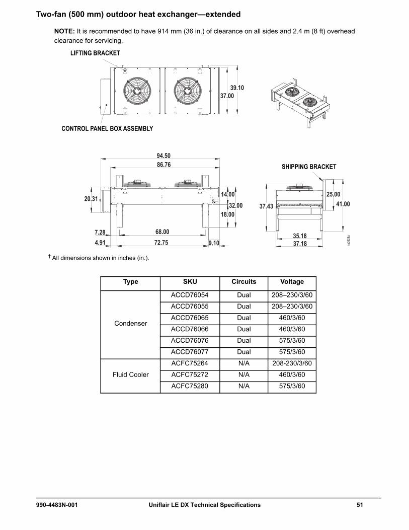
Two-fan (500 mm) outdoor heat exchanger—extended
NOTE: It is recommended to have 914 mm (36 in.) of clearance on all sides and 2.4 m (8 ft) overhead clearance for servicing.
† All dimensions shown in inches (in.).
Type SKU Circuits Voltage
Condenser
ACCD76054 Dual 208–230/3/60
ACCD76055 Dual 208–230/3/60
ACCD76065 Dual 460/3/60
ACCD76066 Dual 460/3/60
ACCD76076 Dual 575/3/60
ACCD76077 Dual 575/3/60
Fluid Cooler
ACFC75264 N/A 208-230/3/60
ACFC75272 N/A 460/3/60
ACFC75280 N/A 575/3/60
na39
28a
94.5086.76
20.31
7.284.91
68.0072.75
14.0032.00
18.00
9.10
39.1037.00
37.43
35.1837.18
25.0041.00
LIFTING BRACKET
SHIPPING BRACKET
CONTROL PANEL BOX ASSEMBLY
990-4483N-001 Uniflair LE DX Technical Specifications 51

Two-fan (800 mm) outdoor heat exchanger
NOTE: It is recommended to have 914 mm (36 in.) of clearance on all sides and 2.4 m (8 ft) overhead clearance for servicing.
† All dimensions shown in inches (in.).
Type SKU Circuits Voltage
Condenser
ACCD76058 Dual 208–230/3/60
ACCD76059 Dual 208–230/3/60
ACCD76069 Dual 460/3/60
ACCD76070 Dual 460/3/60
ACCD76080 Dual 575/3/60
ACCD76081 Dual 575/3/60
Fluid Cooler
ACFC75261 N/A 208–230/3/60
ACFC75266 N/A 208–230/3/60
ACFC75269 N/A 460/3/60
ACFC75274 N/A 460/3/60
ACFC75277 N/A 575/3/60
ACFC75282 N/A 575/3/60
na39
30a
52.9248.89 48.89
138.89131.33
7.56
20.3420.6
23.62
106.15116.0012.80
44.29
46.3349.00
37.9855.3254.62
52 Uniflair LE DX Technical Specifications 990-4483N-001

Three-fan (500 mm) outdoor heat exchanger
NOTE: It is recommended to have 914 mm (36 in.) of clearance on all sides and 2.4 m (8 ft) overhead clearance for servicing.
† All dimensions shown in inches (in.).
Type SKU Circuits Voltage
Condenser
ACCD76056 Dual 208–230/3/60
ACCD76057 Dual 208–230/3/60
ACCD76067 Dual 460/3/60
ACCD76068 Dual 460/3/60
ACCD76078 Dual 575/3/60
ACCD76079 Dual 575/3/60
Fluid Cooler
ACFC75260 N/A 208–230/3/60
ACFC75265 N/A 208–230/3/60
ACFC75268 N/A 460/3/60
ACFC75273 N/A 460/3/60
ACFC75276 N/A 575/3/60
ACFC75281 N/A 575/3/60
na39
29a
126.50118.76
20.31
7.284.91
100.00104.75
14.0032.00
18.00
9.11
37.43
25.0041.00
35.1837.18
37.0039.16
LIFTING BRACKET
SHIPPING BRACKET
CONTROL PANEL BOX ASSEMBLY
990-4483N-001 Uniflair LE DX Technical Specifications 53

Three-fan (800 mm) outdoor heat exchanger
NOTE: It is recommended to have 914 mm (36 in.) of clearance on all sides and 2.4 m (8 ft) overhead clearance for servicing.
† All dimensions shown in inches (in.).
Type SKU Circuits Voltage
Condenser
ACCD76060 Dual 208–230/3/60
ACCD76071 Dual 460/3/60
ACCD76082 Dual 575/3/60
Fluid Cooler
ACFC75262 N/A 208–230/3/60
ACFC75270 N/A 460/3/60
ACFC75278 N/A 575/3/60
na39
31a
48.8048.80
52.97
20.6744.29
23.62
54.61
46.1548.92
37.9855.3120.34
7.49174.00
111.0853.0712.79
197.00189.36
UNIT SHIPPING BRACKET
INSTALLATION BRACKET
ELECTRICAL BOX UNIT LIFT LEG BRACKET
24 in. LEG KIT ASSEMBLY
54 Uniflair LE DX Technical Specifications 990-4483N-001

Five-fan (800 mm) outdoor heat exchanger
NOTE: It is recommended to have 914 mm (36 in.) of clearance on all sides and 2.4 m (8 ft) overhead clearance for servicing.
† All dimensions shown in inches (in.).
Type SKU Circuits Voltage
Fluid Cooler
ACFC75267 N/A 208–230/3/60
ACFC75275 N/A 460/3/60
ACFC75283 N/A 575/3/60
na39
97a
48.80 53.0648.89
313.00305.44
7.48
20.34
290.09169.16 111.08
20.67
23.62
12.80
44.29 55.31 54.61
46.1749.00
37.98
ELECTRICAL BOX
990-4483N-001 Uniflair LE DX Technical Specifications 55

Six-fan (800 mm) outdoor heat exchanger
NOTE: It is recommended to have 914 mm (36 in.) of clearance on all sides and 2.4 m (8 ft) overhead clearance for servicing.
† All dimensions shown in inches (in.).
Type SKU Circuits Voltage
Fluid Cooler
ACFC75263 N/A 208–230/3/60
ACFC75271 N/A 460/3/60
ACFC75279 N/A 575/3/60
na39
96a
48.8952.97
48.80
20.34
371.06363.50
7.51 111.13 116.07
348.1212.79
23.6244.29
20.67
111.07
55.3137.98
54.61
46.1749.00
ELECTRICAL BOX
56 Uniflair LE DX Technical Specifications 990-4483N-001

Pump DataPump performance dataLetter in Graph SKU HP Voltage FLA MCA MOP Line/Size (in.)
A
ACPP2320
2
208/3/60 7.5 10 20Suction/1.5
Discharge/1.25ACPP2324 460/3/60 3.4 5 10
ACPP2328 575/3/60 2.7 5 10
B
ACPP2321
2
208/3/60 7.5 10 20Suction/2
Discharge/1.5ACPP2325 460/3/60 3.4 5 10
ACPP2329 575/3/60 2.7 5 10
C
ACPP2322
5
208/3/60 16.7 21 40Suction/2.5
Discharge/2ACPP2326 460/3/60 7.6 10 20
ACPP2330 575/3/60 6.1 10 20
D
ACPP2323
7.5
208/3/60 24 30 55Suction/2.5
Discharge/2ACPP2327 460/3/60 11 14 25
ACPP2331 575/3/60 8.8 14 25
120
140
160
40
60
80
100
120
0
20
40
0 50 100 150 200 250 300
na40
16a
3500 RPM
D
C
B
A
GALLONS PER MINUTE
TOTA
L FE
ET O
F HE
AD
990-4483N-001 Uniflair LE DX Technical Specifications 57
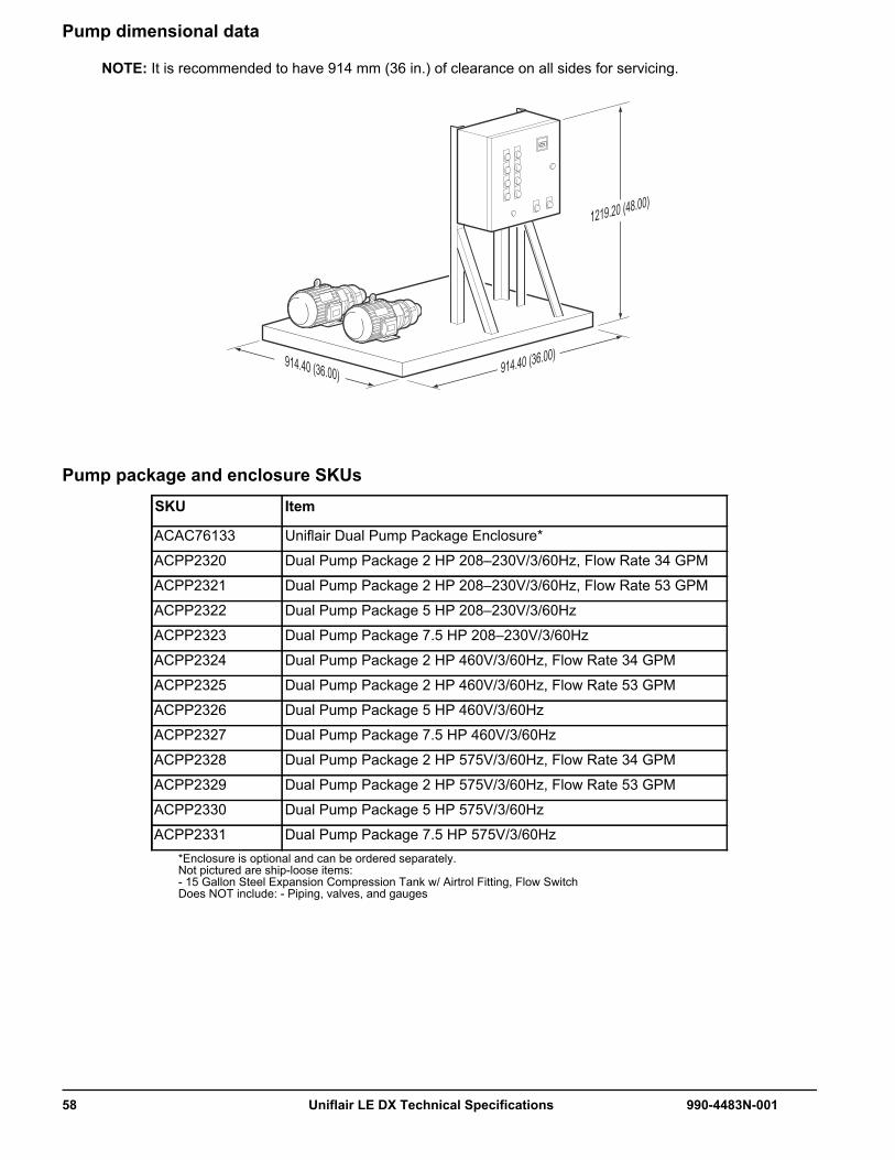
Pump dimensional data
NOTE: It is recommended to have 914 mm (36 in.) of clearance on all sides for servicing.
Pump package and enclosure SKUsSKU Item
ACAC76133 Uniflair Dual Pump Package Enclosure*
ACPP2320 Dual Pump Package 2 HP 208–230V/3/60Hz, Flow Rate 34 GPM
ACPP2321 Dual Pump Package 2 HP 208–230V/3/60Hz, Flow Rate 53 GPM
ACPP2322 Dual Pump Package 5 HP 208–230V/3/60Hz
ACPP2323 Dual Pump Package 7.5 HP 208–230V/3/60Hz
ACPP2324 Dual Pump Package 2 HP 460V/3/60Hz, Flow Rate 34 GPM
ACPP2325 Dual Pump Package 2 HP 460V/3/60Hz, Flow Rate 53 GPM
ACPP2326 Dual Pump Package 5 HP 460V/3/60Hz
ACPP2327 Dual Pump Package 7.5 HP 460V/3/60Hz
ACPP2328 Dual Pump Package 2 HP 575V/3/60Hz, Flow Rate 34 GPM
ACPP2329 Dual Pump Package 2 HP 575V/3/60Hz, Flow Rate 53 GPM
ACPP2330 Dual Pump Package 5 HP 575V/3/60Hz
ACPP2331 Dual Pump Package 7.5 HP 575V/3/60Hz*Enclosure is optional and can be ordered separately.Not pictured are ship-loose items: - 15 Gallon Steel Expansion Compression Tank w/ Airtrol Fitting, Flow SwitchDoes NOT include: - Piping, valves, and gauges
914.40 (36.00) 914.40 (36.00)
1219.20 (48.00)
58 Uniflair LE DX Technical Specifications 990-4483N-001

Plumbing and Electrical AccessFloor cutout dimensions
*First asterisk represents heat rejection method*Second asterisk represents “D”, “G”, “L” in model number.
Model Frame SizeDimensions mm (in.)
A B
DownflowTD*V0511* 3 900 (35.43) 653 (25.70)TD*V0921* 4 1200 (47.24) 769 (30.28)TD*V1121*
5 1610 (63.39) 769 (30.28)TD*V1422*TD*V1622* 6 2060 (81.10) 769 (30.28)TD*V1822*
7 2492 (98.11) 775 (30.51)TD*V2242*TD*V2542*TD*V2842*TD*V3342*
Upflow Bottom ReturnTU*V0511* 3 900 (35.43) 653 (25.70)TU*V0921* 4 1200 (47.24) 769 (30.28)TU*V1121*
5 1610 (63.39) 769 (30.28)TU*V1422*TU*V1622* 6 2060 (81.10) 769 (30.28)TD*V1822*
7 2492 (98.11) 775 (30.51)TD*V2242*TD*V2542*TD*V2842*
A
B
990-4483N-001 Uniflair LE DX Technical Specifications 59
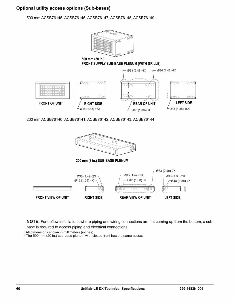
Optional utility access options (Sub-bases)
500 mm ACSB76145, ACSB76146, ACSB76147, ACSB76148, ACSB76149
200 mm ACSB76140, ACSB76141, ACSB76142, ACSB76143, ACSB76144
NOTE: For upflow installations where piping and wiring connections are not coming up from the bottom, a sub-base is required to access piping and electrical connections.
† All dimensions shown in millimeters (inches).† The 500 mm (20 in.) sub-base plenum with closed front has the same access.
Ø48 (1.88) 16X Ø48 (1.88) 16XØ48 (1.88) 8X
Ø63 (2.48) 4X Ø36 (1.42) 4X
na36
97a
500 mm (20 in.)FRONT SUPPLY SUB-BASE PLENUM (WITH GRILLE)
RIGHT SIDE REAR OF UNIT LEFT SIDEFRONT OF UNIT
na37
01a
Ø48 (1.88) 4X Ø48 (1.88) 6X Ø48 (1.88) 4XØ36 (1.88) 2X
Ø63 (2.48) 2X
Ø36 (1.42) 2X Ø36 (1.42) 2X
200 mm (8 in.) SUB-BASE PLENUM
RIGHT SIDE REAR VIEW OF UNIT LEFT SIDEFRONT VIEW OF UNIT
60 Uniflair LE DX Technical Specifications 990-4483N-001
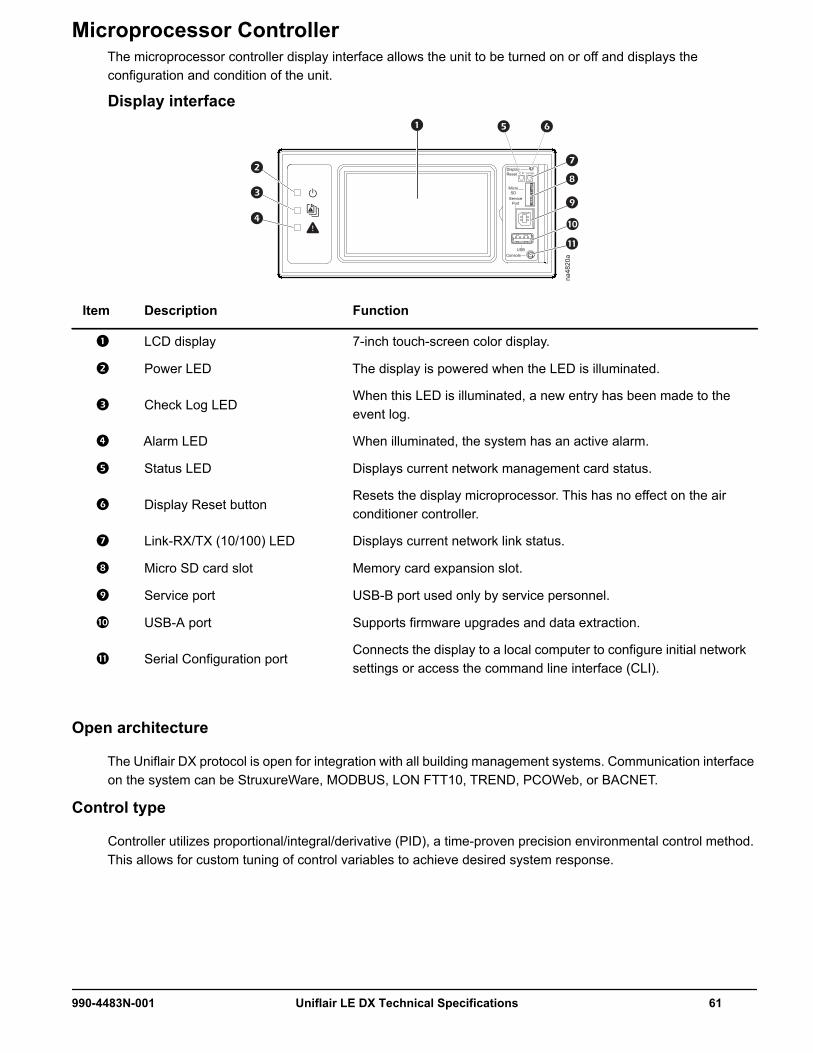
Microprocessor ControllerThe microprocessor controller display interface allows the unit to be turned on or off and displays the configuration and condition of the unit.
Display interface
Open architecture
The Uniflair DX protocol is open for integration with all building management systems. Communication interface on the system can be StruxureWare, MODBUS, LON FTT10, TREND, PCOWeb, or BACNET.
Control type
Controller utilizes proportional/integral/derivative (PID), a time-proven precision environmental control method. This allows for custom tuning of control variables to achieve desired system response.
Item Description Function
LCD display 7-inch touch-screen color display.
Power LED The display is powered when the LED is illuminated.
Check Log LEDWhen this LED is illuminated, a new entry has been made to the event log.
Alarm LED When illuminated, the system has an active alarm.
Status LED Displays current network management card status.
Display Reset buttonResets the display microprocessor. This has no effect on the air conditioner controller.
Link-RX/TX (10/100) LED Displays current network link status.
Micro SD card slot Memory card expansion slot.
Service port USB-B port used only by service personnel.
USB-A port Supports firmware upgrades and data extraction.
Serial Configuration portConnects the display to a local computer to configure initial network settings or access the command line interface (CLI).
DisplayReset
MicroSD
ServicePort
USBConsole
10/100
na48
20a
990-4483N-001 Uniflair LE DX Technical Specifications 61

Functions
• Input/Output Module Programming• Event Logging• Redundant Unit Group• Static Pressure Adjustment• Status Report• System Control
Logging
The event log keeps a record of all alarms and events. Each event log contains a time/date stamp as well as operating conditions at the time of occurrence. The controller also displays run time, in hours, for major components (air filters, fans, compressors, heaters, and humidifier).
The data log displays temperature and other data measurements from the cooling unit.
Control
The touch-screen LCD display interface provided on Uniflair DX units is protected by a configurable password and provides access to information and settings for the unit.
• Fan Speed Setpoint• High Humidity Alarm• High Temperature Alarm• Humidity Setpoint• Low Humidity Alarm• Low Temperature Alarm• Dual Temperature Setpoint• Set Date/Time• Remote Unit Switch On/Off• Compressor Sequencing • Alarms• Operating Time Scheduling• Manual Control of Components
62 Uniflair LE DX Technical Specifications 990-4483N-001

Alarms
• High/Low Temperature Threshold Exceeded• High/Low Humidity Threshold Exceeded• Supply Air Temperature Threshold Exceeded• Return Air Sensor Error Detected Alarm• High/Low Airflow• Humidifier• Smoke Detected• Electric Heater Over Temperature• Electronic Expansion Valve Error• High/Low Pressure• Circuit 1 Chilled Water High Temperature Threshold Exceeded• Circuit 1 Chilled Water Temperature too High for Dehumidification• Circuit 1 Entering Chilled Water Temperature Sensor Error Detected Alarm• Circuit 1 Leaving Chilled Water Temperature Sensor Error Detected Alarm• Dual Circuit Expansion Board Error Detected• Digital 2/4/6 Input Abnormal• External Sensor Threshold Exceeded• Supply Air Sensor Error Detected• Air Filter Clogged• Water Detected Fault• Humidity Sensor Error Detected Alarm• Hot Water Sensor Error Detected Alarm• Outdoor Temperature Sensor Error Detected Alarm• EEPROM Error Detected Alarm• EXV Error Alarm
990-4483N-001 Uniflair LE DX Technical Specifications 63

Warranty
Three-Phase Power Products or Cooling Solutions One-Year Factory WarrantyThe limited warranty provided by Schneider Electric™ in this Statement of Limited Factory Warranty applies only to products you purchase for your commercial or industrial use in the ordinary course of your business.
Terms of warrantySchneider Electric warrants that the product shall be free from defects in materials and workmanship for a period of one year from the date of product start-up when start-up is performed by Schneider Electric authorized service personnel and occurs within six months of the Schneider Electric shipment date. This warranty covers repairing or replacing any defective parts including on-site labor and travel. In the event that the product fails to meet the foregoing warranty criteria, the warranty covers repairing or replacing defective parts at the sole discretion of Schneider Electric for a period of one year from the shipment date. For Schneider Electric cooling solutions, this warranty does not cover circuit breaker resetting, loss of refrigerant, consumables, or preventive maintenance items. Repair or replacement of a defective product or part thereof does not extend the original warranty period. Any parts furnished under this warranty may be new or factory-remanufactured.
Non-transferable warranty This warranty is extended to the first person, firm, association or corporation (herein referred to by “You” or “Your”) for whom the Schneider Electric product specified herein has been purchased. This warranty is not transferable or assignable without the prior written permission of Schneider Electric.
Assignment of warrantiesSchneider Electric will assign you any warranties which are made by manufacturers and suppliers of components of the Schneider Electric product and which are assignable. Any such warranties are assigned “AS IS” and Schneider Electric makes no representation as to the effectiveness or extent of such warranties, assumes no responsibility for any matters which may be warranted by such manufacturers or suppliers and extends no coverage under this Warranty to such components.
Drawings and descriptionsSchneider Electric warrants for the warranty period and on the terms of the warranty set forth herein that the Schneider Electric product will substantially conform to the descriptions contained in the Schneider Electric Official Published Specifications or any of the drawings certified and agreed to by contract with Schneider Electric if applicable thereto (“Specifications”). It is understood that the specifications are not warranties of performance and not warranties of fitness for a particular purpose.
64 Uniflair LE DX Technical Specifications 990-4483N-001

ExclusionsSchneider Electric shall not be liable under the warranty if its testing and examination disclose that the alleged defect in the product does not exist or was caused by end user or any third person’s misuse, negligence, improper installation or testing. Further, Schneider Electric shall not be liable under the warranty for unauthorized attempts to repair or modify wrong or inadequate electrical voltage or connection, inappropriate on-site operation conditions, corrosive atmosphere, repair, installation, start-up by non-Schneider Electric designated personnel, a change in location or operating use, exposure to the elements, Acts of God, fire, theft, or installation contrary to Schneider Electric recommendations or specifications or in any event if the Schneider Electric serial number has been altered, defaced, or removed, or any other cause beyond the range of the intended use.
THERE ARE NO WARRANTIES, EXPRESS OR IMPLIED, BY OPERATION OF LAW OR OTHERWISE, OF PRODUCTS SOLD, SERVICED OR FURNISHED UNDER THIS AGREEMENT OR IN CONNECTION HEREWITH. SCHNEIDER ELECTRIC DISCLAIMS ALL IMPLIED WARRANTIES OF MERCHANTABILITY, SATISFACTION AND FITNESS FOR A PARTICULAR PURPOSE. SCHNEIDER ELECTRIC EXPRESS WARRANTIES WILL NOT BE ENLARGED, DIMINISHED, OR AFFECTED BY AND NO OBLIGATION OR LIABILITY WILL ARISE OUT OF, SCHNEIDER ELECTRIC RENDERING OF TECHNICAL OR OTHER ADVICE OR SERVICE IN CONNECTION WITH THE PRODUCTS. THE FOREGOING WARRANTIES AND REMEDIES ARE EXCLUSIVE AND IN LIEU OF ALL OTHER WARRANTIES AND REMEDIES. THE WARRANTIES SET FORTH ABOVE CONSTITUTE SCHNEIDER ELECTRIC’S SOLE LIABILITY AND PURCHASER’S EXCLUSIVE REMEDY FOR ANY BREACH OF SUCH WARRANTIES. SCHNEIDER ELECTRIC WARRANTIES EXTEND ONLY TO PURCHASER AND ARE NOT EXTENDED TO ANY THIRD PARTIES.
IN NO EVENT SHALL SCHNEIDER ELECTRIC, ITS OFFICERS, DIRECTORS, AFFILIATES OR EMPLOYEES BE LIABLE FOR ANY FORM OF INDIRECT, SPECIAL, CONSEQUENTIAL OR PUNITIVE DAMAGES, ARISING OUT OF THE USE, SERVICE OR INSTALLATION, OF THE PRODUCTS, WHETHER SUCH DAMAGES ARISE IN CONTRACT OR TORT, IRRESPECTIVE OF FAULT, NEGLIGENCE OR STRICT LIABILITY OR WHETHER SCHNEIDER ELECTRIC HAS BEEN ADVISED IN ADVANCE OF THE POSSIBILITY OF SUCH DAMAGES. SPECIFICALLY, SCHNEIDER ELECTRIC IS NOT LIABLE FOR ANY COSTS, SUCH AS LOST PROFITS OR REVENUE, LOSS OF EQUIPMENT, LOSS OF USE OF EQUIPMENT, LOSS OF SOFTWARE, LOSS OF DATA, COSTS OF SUBSTITUENTS, CLAIMS BY THIRD PARTIES, OR OTHERWISE.
NO SALESMAN, EMPLOYEE OR AGENT OF SCHNEIDER ELECTRIC IS AUTHORIZED TO ADD TO OR VARY THE TERMS OF THIS WARRANTY. WARRANTY TERMS MAY BE MODIFIED, IF AT ALL, ONLY IN WRITING SIGNED BY A SCHNEIDER ELECTRIC OFFICER AND LEGAL DEPARTMENT.
Warranty claims Customers with warranty claims issues may access the Schneider Electric customer support network through the Support page of the Schneider Electric Web site, www.schneider-electric.com/ > Support > Operations around the world. Select your country from the country selection pull-down menu at the top of the Web page. Select the Support tab to obtain contact information for customer support in your region.
990-4483N-001 Uniflair LE DX Technical Specifications 65


Worldwide Customer SupportCustomer support for this or any other product is available at no charge in any of the following ways:
• Visit the Schneider Electric Web site to access documents in the Schneider Electric Knowledge Base and to submit customer support requests.– www.schneiderelectric.com (Corporate Headquarters)
Connect to localized Schneider Electric Web sites for specific countries, each of which provides customer support information.
– www.schneiderelectric.com/support/Global support searching Schneider Electric Knowledge Base and using e-support.
• Contact the Schneider Electric Customer Support Center by telephone or e-mail.– Local, country-specific centers: go to www.schneiderelectric.com > Support > Operations
around the world for contact information.
For information on how to obtain local customer support, contact the representative or other distributors from whom you purchased your product.
As standards, specifications, and designs change from time to time, please ask for confirmation of the information given in this publication.© 2016 Schneider Electric. All Rights Reserved.Uniflair and the Schneider Electric logo are trademarks owned by Schneider Electric Industries SAS S.A.S., or its affiliated companies. All other trademarks are the property of their respective owners.
2/2016990-4483N-001