Unified MPLS for Mobile Transport · • Core and Aggregation Networks enable Unified MPLS...
63
Transcript of Unified MPLS for Mobile Transport · • Core and Aggregation Networks enable Unified MPLS...
© 2012 Cisco and/or its affiliates. All rights reserved. BRKSPM-3400 Cisco Public
Unified MPLS for Mobile Transport
2
Agenda
Mobile Market Dynamics
Unified MPLS for Mobile Transport (UMMT) system overview
UMMT Functional Considerations
‒ QoS
‒ Resiliency
‒ OAM and PM
‒ Synchronization Distribution
‒ Security
‒ SDN Perspectives
Summary and Key Takeaways
3
Mobile Market Dynamics
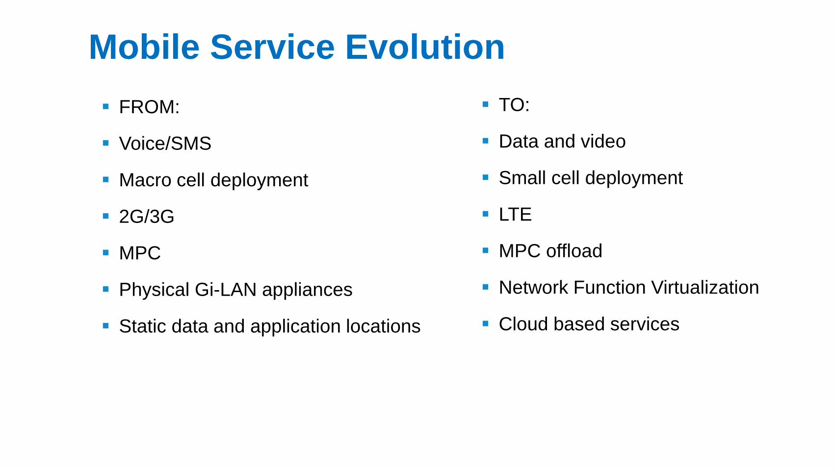
Mobile Service Evolution
FROM:
Voice/SMS
Macro cell deployment
2G/3G
MPC
Physical Gi-LAN appliances
Static data and application locations
TO:
Data and video
Small cell deployment
LTE
MPC offload
Network Function Virtualization
Cloud based services
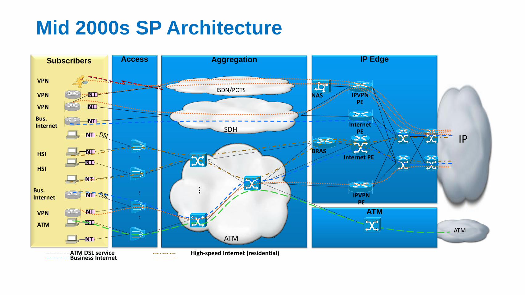
Mid 2000s SP Architecture
IP
ATM
ATM
Subscribers Aggregation
ATM
IP Edge Access
NT
NT BRAS Internet PE
NT
NT
..
NT
NT
NT
NT
..
… …
HSI
HSI
Bus. Internet
ATM
Business Internet ATM DSL service High-speed Internet (residential)
VPN
ISDN/POTS
SDH NT Bus.
Internet
VPN NT
IPVPN PE
IPVPN PE
Internet PE
VPN
NAS NT VPN
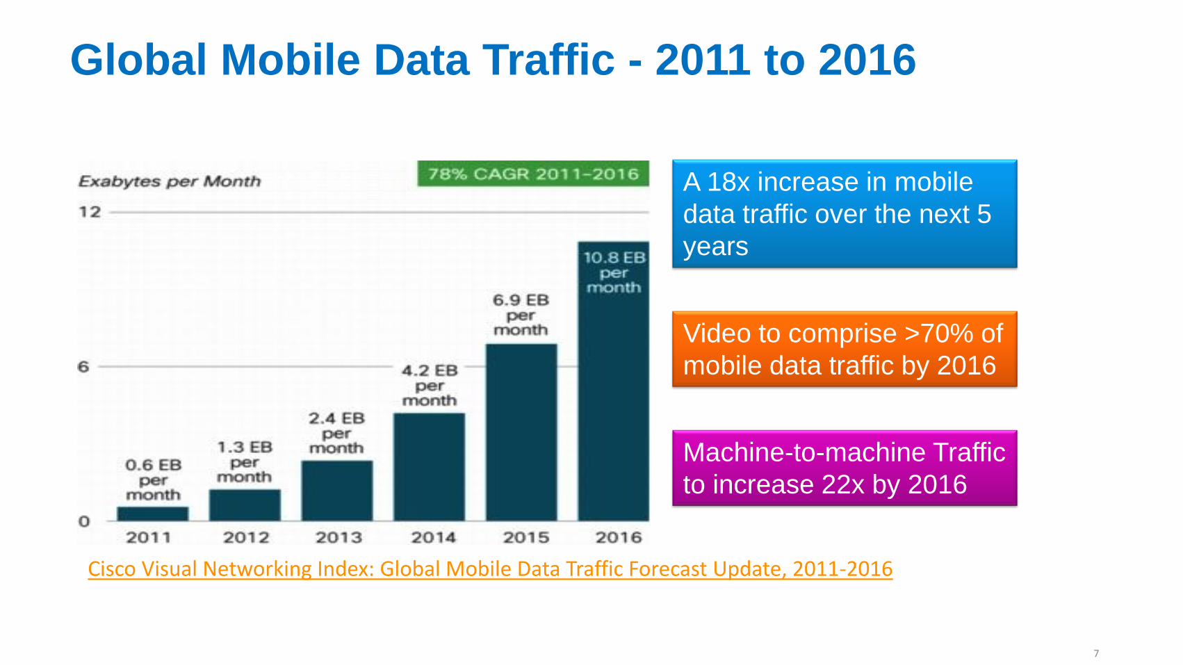
Global Mobile Data Traffic - 2011 to 2016
A 18x increase in mobile
data traffic over the next 5
years
Video to comprise >70% of
mobile data traffic by 2016
Machine-to-machine Traffic
to increase 22x by 2016
Cisco Visual Networking Index: Global Mobile Data Traffic Forecast Update, 2011-2016
7
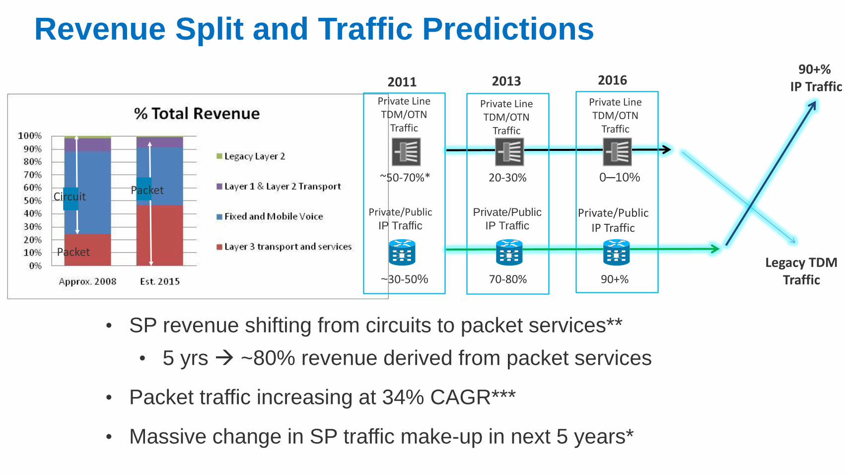
Revenue Split and Traffic Predictions
Packet
Circuit Packet
90+% IP Traffic
Private Line TDM/OTN
Traffic
Private/Public IP Traffic
2011
~30-50%
~50-70%*
2013 2016
Private Line TDM/OTN
Traffic
Private Line TDM/OTN
Traffic
20-30% 0─10%
Private/Public IP Traffic
Private/Public
IP Traffic
70-80% 90+%
Legacy TDM Traffic
• SP revenue shifting from circuits to packet services**
• 5 yrs ~80% revenue derived from packet services
• Packet traffic increasing at 34% CAGR***
• Massive change in SP traffic make-up in next 5 years*
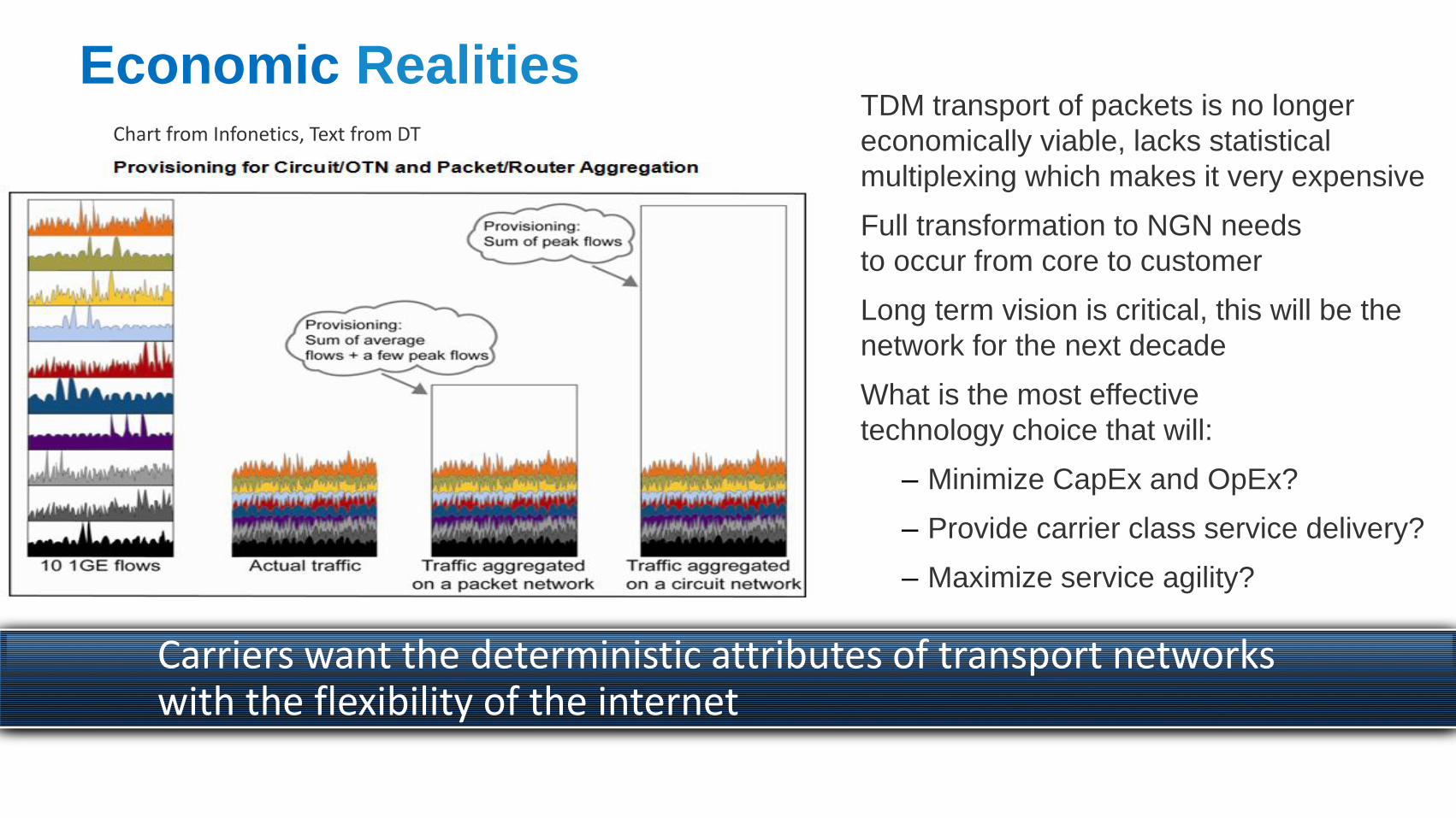
Economic Realities TDM transport of packets is no longer
economically viable, lacks statistical
multiplexing which makes it very expensive
Full transformation to NGN needs
to occur from core to customer
Long term vision is critical, this will be the
network for the next decade
What is the most effective
technology choice that will:
‒ Minimize CapEx and OpEx?
‒ Provide carrier class service delivery?
‒ Maximize service agility?
Carriers want the deterministic attributes of transport networks with the flexibility of the internet
Chart from Infonetics, Text from DT
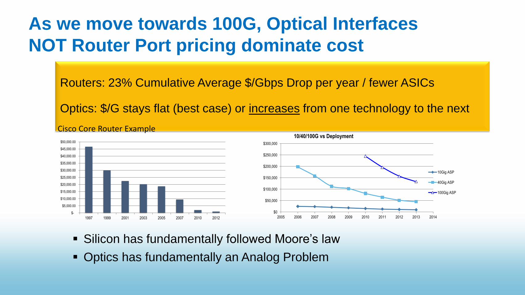
As we move towards 100G, Optical Interfaces
NOT Router Port pricing dominate cost
Silicon has fundamentally followed Moore’s law
Optics has fundamentally an Analog Problem
$-
$5,000.00
$10,000.00
$15,000.00
$20,000.00
$25,000.00
$30,000.00
$35,000.00
$40,000.00
$45,000.00
$50,000.00
1997 1999 2001 2003 2005 2007 2010 2012
Routers: 23% Cumulative Average $/Gbps Drop per year / fewer ASICs Optics: $/G stays flat (best case) or increases from one technology to the next
$0
$50,000
$100,000
$150,000
$200,000
$250,000
$300,000
2005 2006 2007 2008 2009 2010 2011 2012 2013 2014
10/40/100G vs Deployment
10Gig ASP
40Gig ASP
100Gig ASP
Cisco Core Router Example
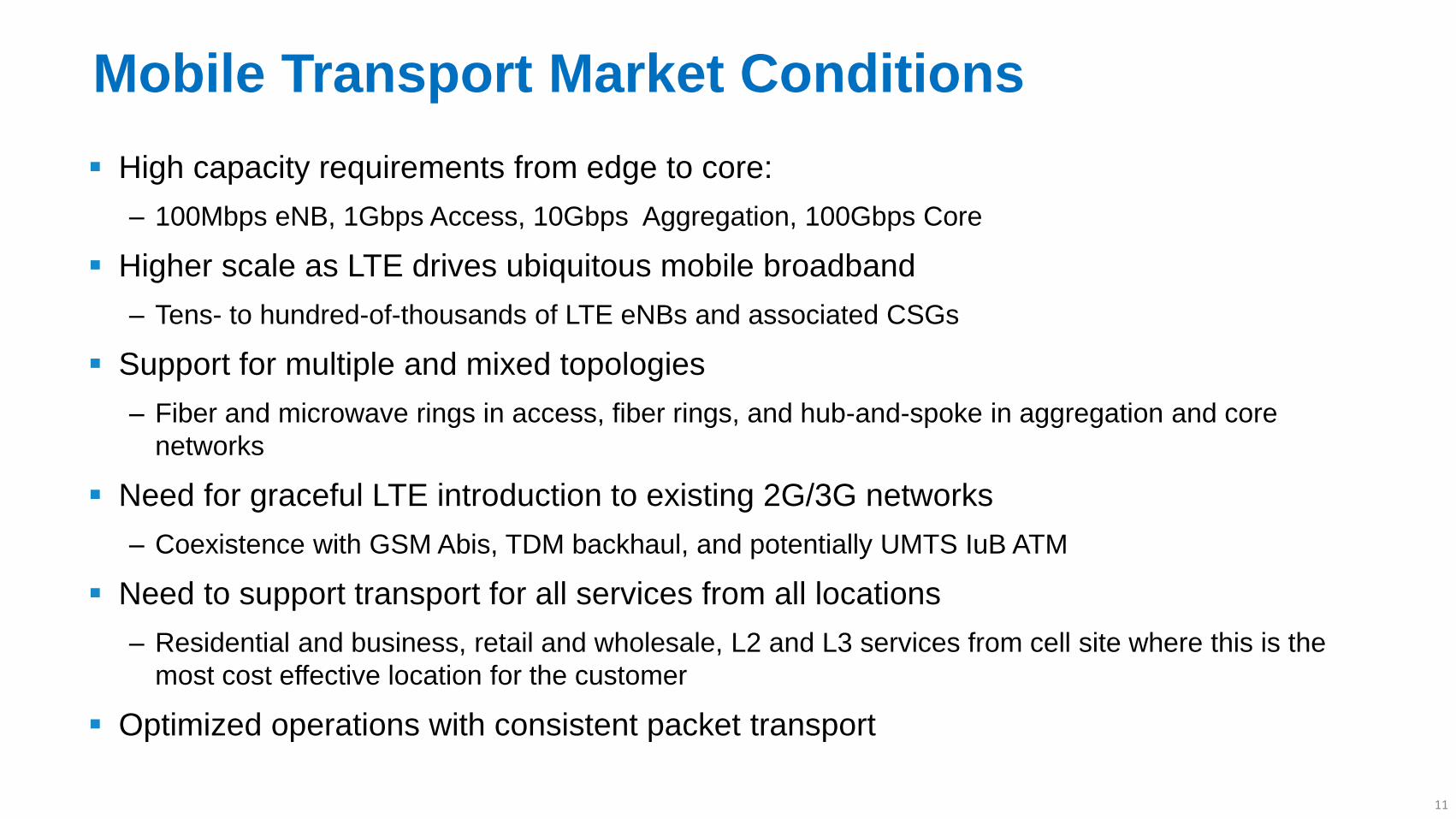
Mobile Transport Market Conditions
High capacity requirements from edge to core:
‒ 100Mbps eNB, 1Gbps Access, 10Gbps Aggregation, 100Gbps Core
Higher scale as LTE drives ubiquitous mobile broadband
‒ Tens- to hundred-of-thousands of LTE eNBs and associated CSGs
Support for multiple and mixed topologies
‒ Fiber and microwave rings in access, fiber rings, and hub-and-spoke in aggregation and core
networks
Need for graceful LTE introduction to existing 2G/3G networks
‒ Coexistence with GSM Abis, TDM backhaul, and potentially UMTS IuB ATM
Need to support transport for all services from all locations
‒ Residential and business, retail and wholesale, L2 and L3 services from cell site where this is the
most cost effective location for the customer
Optimized operations with consistent packet transport
11

UMMT System Overview
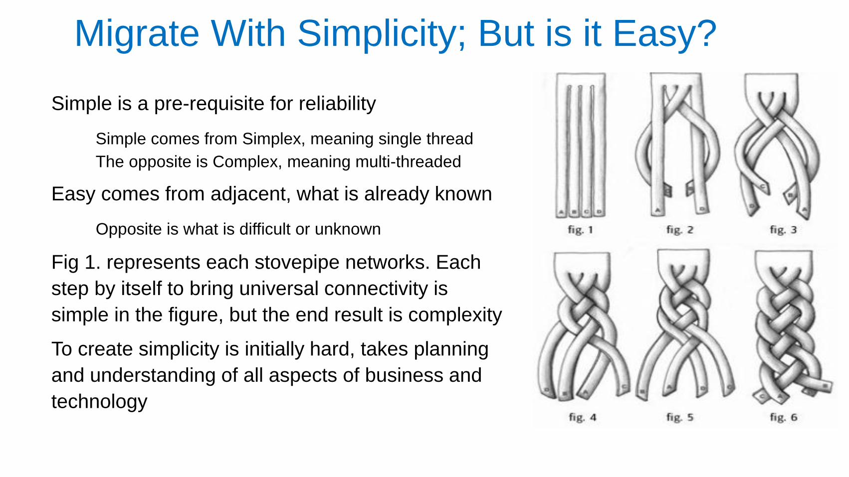
Migrate With Simplicity; But is it Easy?
Simple is a pre-requisite for reliability
Simple comes from Simplex, meaning single thread
The opposite is Complex, meaning multi-threaded
Easy comes from adjacent, what is already known
Opposite is what is difficult or unknown
Fig 1. represents each stovepipe networks. Each
step by itself to bring universal connectivity is
simple in the figure, but the end result is complexity
To create simplicity is initially hard, takes planning
and understanding of all aspects of business and
technology
MPLS MPLS MPLS
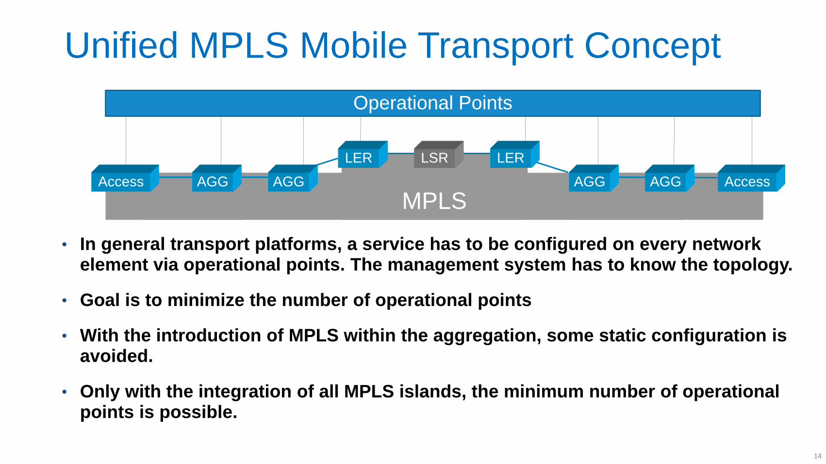
Unified MPLS Mobile Transport Concept
• In general transport platforms, a service has to be configured on every network element via operational points. The management system has to know the topology.
• Goal is to minimize the number of operational points
• With the introduction of MPLS within the aggregation, some static configuration is avoided.
• Only with the integration of all MPLS islands, the minimum number of operational points is possible.
MPLS Access AGG AGG
LER LSR LER
AGG AGG Access
Operational Points
14
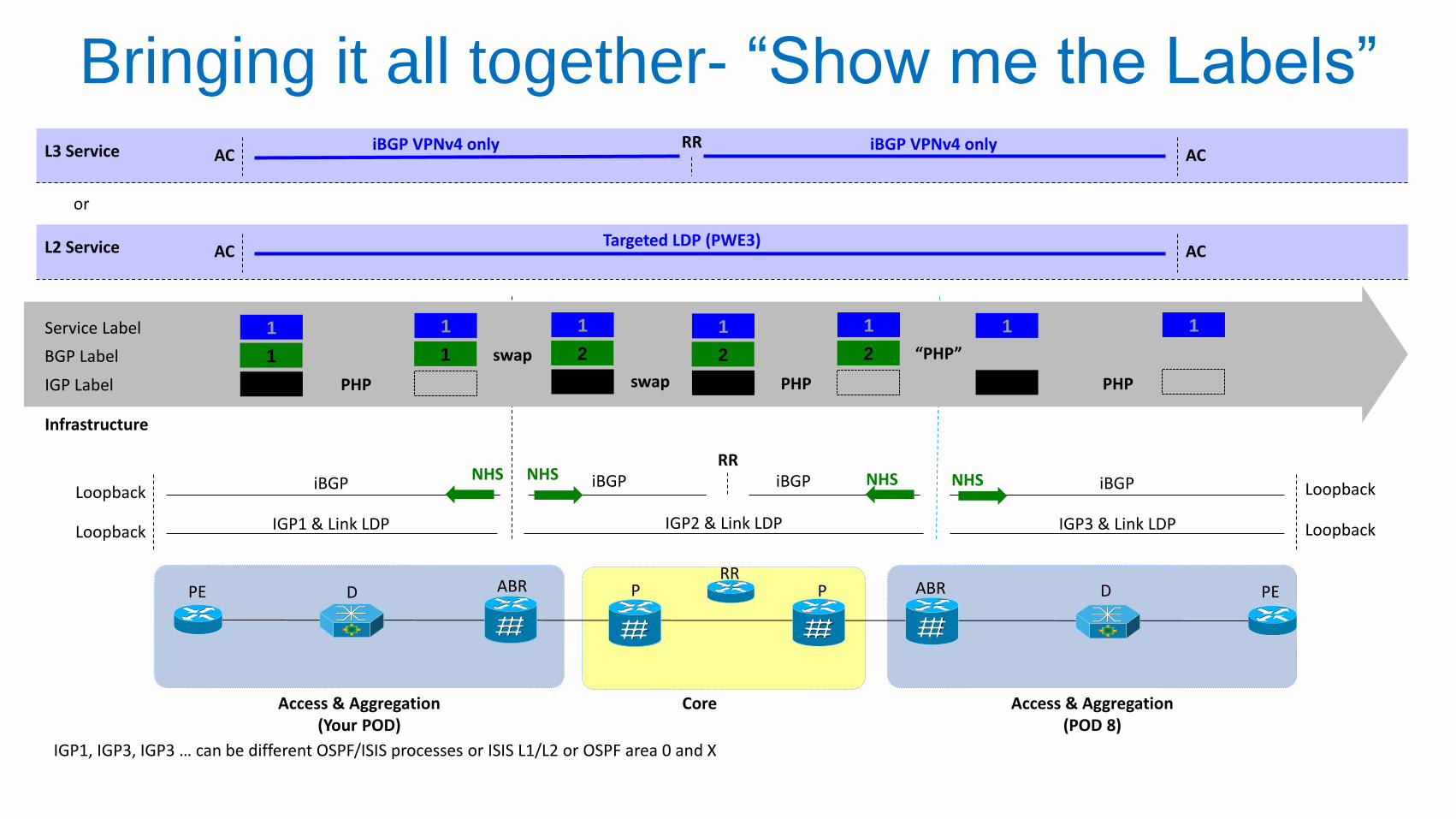
Bringing it all together- “Show me the Labels”
IGP1, IGP3, IGP3 … can be different OSPF/ISIS processes or ISIS L1/L2 or OSPF area 0 and X
IGP1 & Link LDP IGP2 & Link LDP IGP3 & Link LDP
iBGP iBGP iBGP Loopback
Loopback
Loopback
Loopback
NHS NHS
Infrastructure
NHS NHS iBGP RR
1 IGP Label
1 BGP Label
1 Service Label
1
1
2
2
1
2
1 1
3
2
1
4
1
swap
swap “PHP”
PHP PHP PHP
Targeted LDP (PWE3) AC AC L2 Service
iBGP VPNv4 only AC AC L3 Service iBGP VPNv4 only RR
or
Access & Aggregation (Your POD)
Access & Aggregation (POD 8)
Core
RR P P ABR D PE PE D ABR
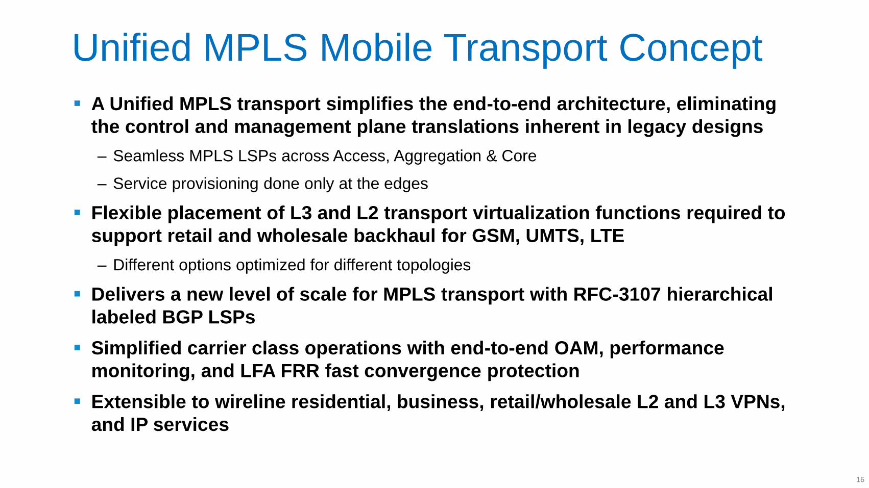
Unified MPLS Mobile Transport Concept
A Unified MPLS transport simplifies the end-to-end architecture, eliminating
the control and management plane translations inherent in legacy designs
‒ Seamless MPLS LSPs across Access, Aggregation & Core
‒ Service provisioning done only at the edges
Flexible placement of L3 and L2 transport virtualization functions required to
support retail and wholesale backhaul for GSM, UMTS, LTE
‒ Different options optimized for different topologies
Delivers a new level of scale for MPLS transport with RFC-3107 hierarchical
labeled BGP LSPs
Simplified carrier class operations with end-to-end OAM, performance
monitoring, and LFA FRR fast convergence protection
Extensible to wireline residential, business, retail/wholesale L2 and L3 VPNs,
and IP services
16
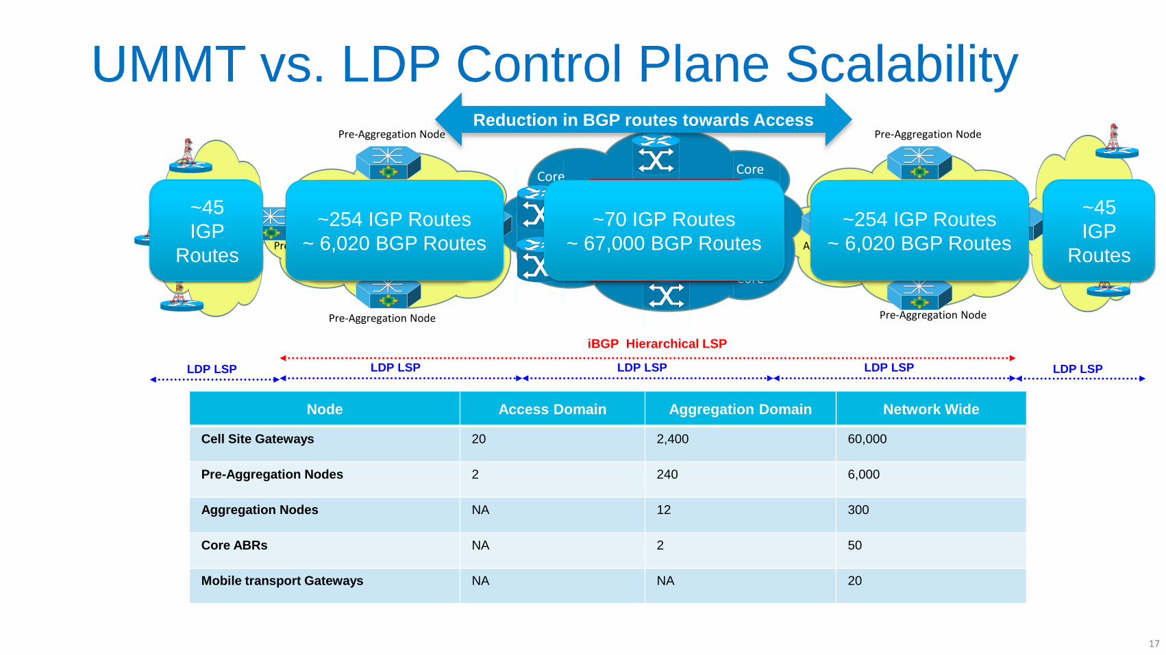
UMMT vs. LDP Control Plane Scalability
Node Access Domain Aggregation Domain Network Wide
Cell Site Gateways 20 2,400 60,000
Pre-Aggregation Nodes 2 240 6,000
Aggregation Nodes NA 12 300
Core ABRs NA 2 50
Mobile transport Gateways NA NA 20
Core Domain MPLS/IP IGP Area
Pre-Aggregation Node
Pre-Aggregation Node
Pre-Aggregation Node
Aggregation Domain MPLS/IP
IGP Area/Process
Pre-Aggregation Node
Pre-Aggregation Node
Pre-Aggregation Node
Aggregation Domain MPLS/IP
IGP Area/Process
RAN MPLS/IP
IGP Area/Process
RAN MPLS/IP
IGP Area/Process
Core
Core
Core
Core
Aggregation Node
Aggregation Node
~ 67,000
IGP Routes!
~45 IGP
Routes
~45 IGP
Routes
~ 2,500
IGP Routes!
~ 2,500
IGP Routes!
LDP LSP LDP LSP LDP LSP
~254 IGP Routes
~ 6,020 BGP Routes
~45
IGP
Routes
~70 IGP Routes
~ 67,000 BGP Routes
~254 IGP Routes
~ 6,020 BGP Routes
~45
IGP
Routes
LDP LSP LDP LSP LDP LSP LDP LSP LDP LSP
iBGP Hierarchical LSP
Reduction in BGP routes towards Access
17
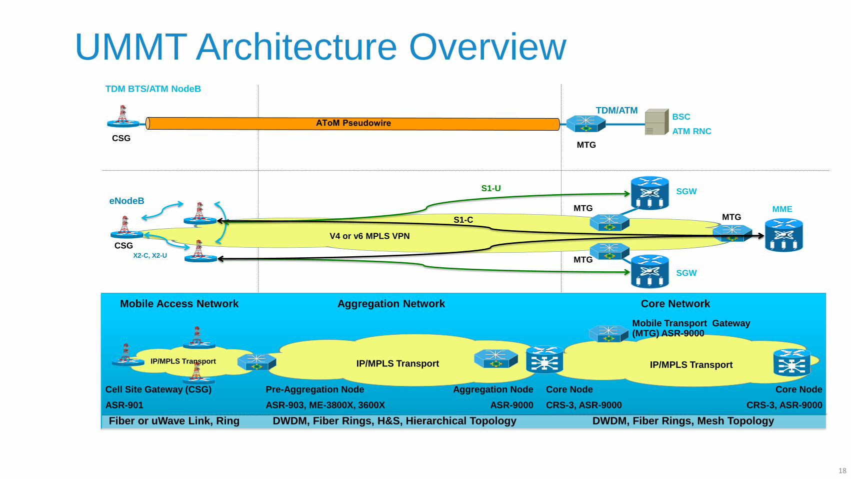
UMMT Architecture Overview
Pre-Aggregation Node
ASR-903, ME-3800X, 3600X
DWDM, Fiber Rings, Mesh Topology DWDM, Fiber Rings, H&S, Hierarchical Topology Fiber or uWave Link, Ring
Core Network Mobile Access Network Aggregation Network
Core Node
CRS-3, ASR-9000
IP/MPLS Transport
IP/MPLS Transport
Core Node
CRS-3, ASR-9000
Cell Site Gateway (CSG)
ASR-901
IP/MPLS Transport
Mobile Transport Gateway (MTG) ASR-9000
Aggregation Node
ASR-9000
TDM/ATM
BSC
ATM RNC
TDM BTS/ATM NodeB
MTG CSG
V4 or v6 MPLS VPN
SGW
SGW
MME
X2-C, X2-U
S1-U
S1-C
eNodeB MTG
MTG
MTG
CSG
18
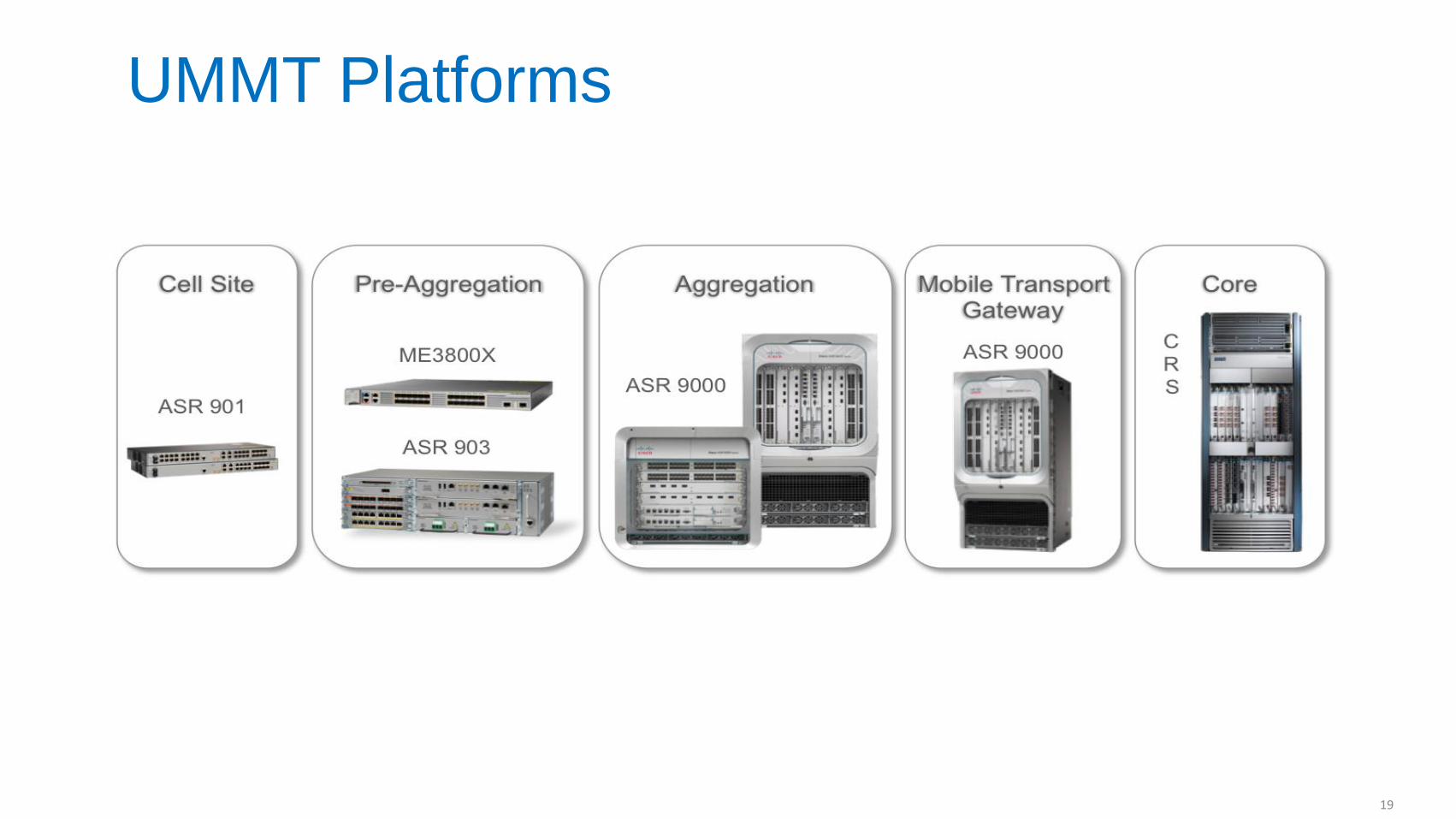
UMMT Platforms
19
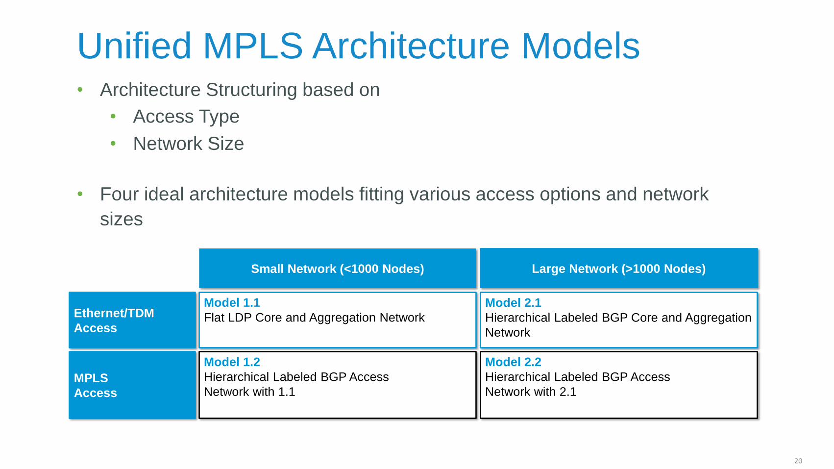
Unified MPLS Architecture Models • Architecture Structuring based on
• Access Type
• Network Size
• Four ideal architecture models fitting various access options and network
sizes
Small Network (<1000 Nodes) Large Network (>1000 Nodes)
Ethernet/TDM
Access
MPLS
Access
Model 1.1
Flat LDP Core and Aggregation Network
Model 1.2
Hierarchical Labeled BGP Access
Network with 1.1
Model 2.1
Hierarchical Labeled BGP Core and Aggregation
Network
Model 2.2
Hierarchical Labeled BGP Access
Network with 2.1
20
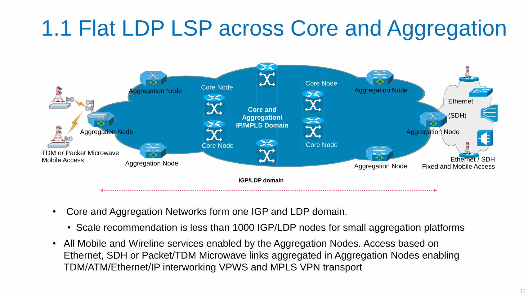
1.1 Flat LDP LSP across Core and Aggregation
• Core and Aggregation Networks form one IGP and LDP domain.
• Scale recommendation is less than 1000 IGP/LDP nodes for small aggregation platforms
• All Mobile and Wireline services enabled by the Aggregation Nodes. Access based on
Ethernet, SDH or Packet/TDM Microwave links aggregated in Aggregation Nodes enabling
TDM/ATM/Ethernet/IP interworking VPWS and MPLS VPN transport
Aggregation Node
Core and
Aggregation\
IP/MPLS Domain
Core Node
Aggregation Node
Core Node
Core Node
Core Node
IGP/LDP domain
Aggregation Node
Aggregation Node
Aggregation Node
Aggregation Node
Aggregation Node
Ethernet (SDH)
Ethernet / SDH Fixed and Mobile Access
TDM or Packet Microwave Mobile Access
21
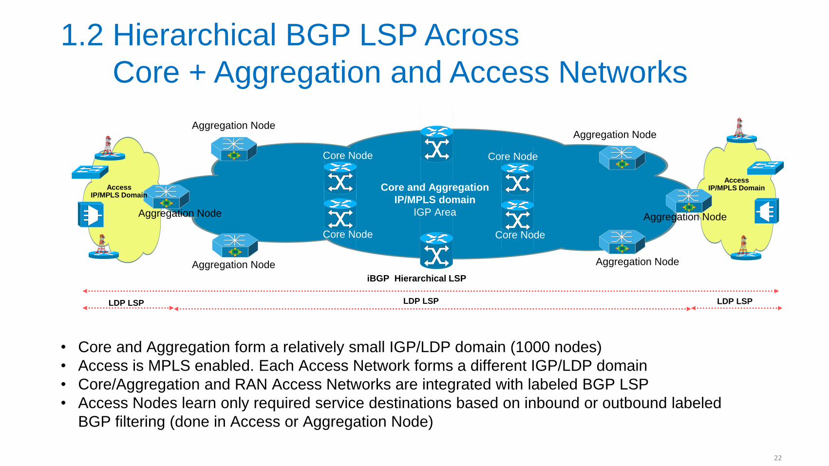
1.2 Hierarchical BGP LSP Across
Core + Aggregation and Access Networks
• Core and Aggregation form a relatively small IGP/LDP domain (1000 nodes)
• Access is MPLS enabled. Each Access Network forms a different IGP/LDP domain
• Core/Aggregation and RAN Access Networks are integrated with labeled BGP LSP
• Access Nodes learn only required service destinations based on inbound or outbound labeled
BGP filtering (done in Access or Aggregation Node)
Core and Aggregation
IP/MPLS domain
IGP Area
Aggregation Node
Aggregation Node
Aggregation Node
Aggregation Node
Aggregation Node
Aggregation Node
Access IP/MPLS Domain
Core Node
Core Node
Core Node
Core Node
LDP LSP LDP LSP LDP LSP
iBGP Hierarchical LSP
Access IP/MPLS Domain
22
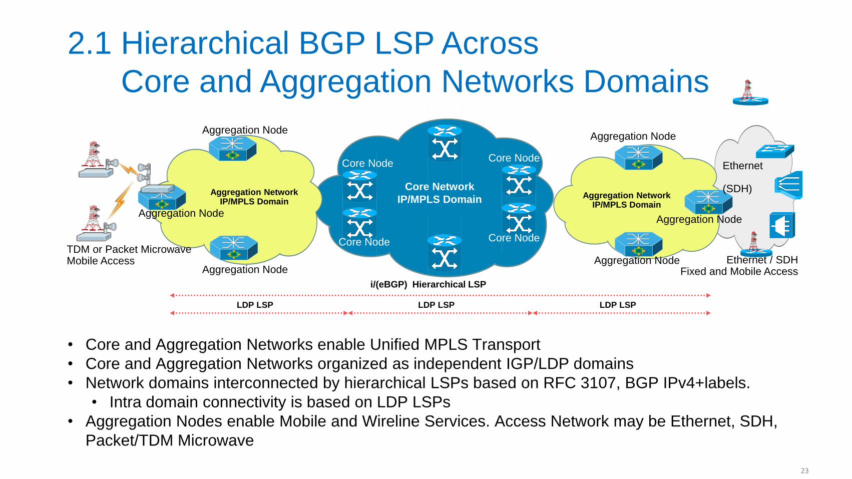
2.1 Hierarchical BGP LSP Across
Core and Aggregation Networks Domains
• Core and Aggregation Networks enable Unified MPLS Transport
• Core and Aggregation Networks organized as independent IGP/LDP domains
• Network domains interconnected by hierarchical LSPs based on RFC 3107, BGP IPv4+labels.
• Intra domain connectivity is based on LDP LSPs
• Aggregation Nodes enable Mobile and Wireline Services. Access Network may be Ethernet, SDH,
Packet/TDM Microwave
Core Network
IP/MPLS Domain
Aggregation Node
Aggregation Node
Aggregation Node
Aggregation Network IP/MPLS Domain
Aggregation Node
Aggregation Node
Aggregation Node
Aggregation Network IP/MPLS Domain
Core Node
Core Node
Core Node
Core Node
LDP LSP LDP LSP LDP LSP
i/(eBGP) Hierarchical LSP
Ethernet (SDH)
Ethernet / SDH Fixed and Mobile Access
TDM or Packet Microwave Mobile Access
23
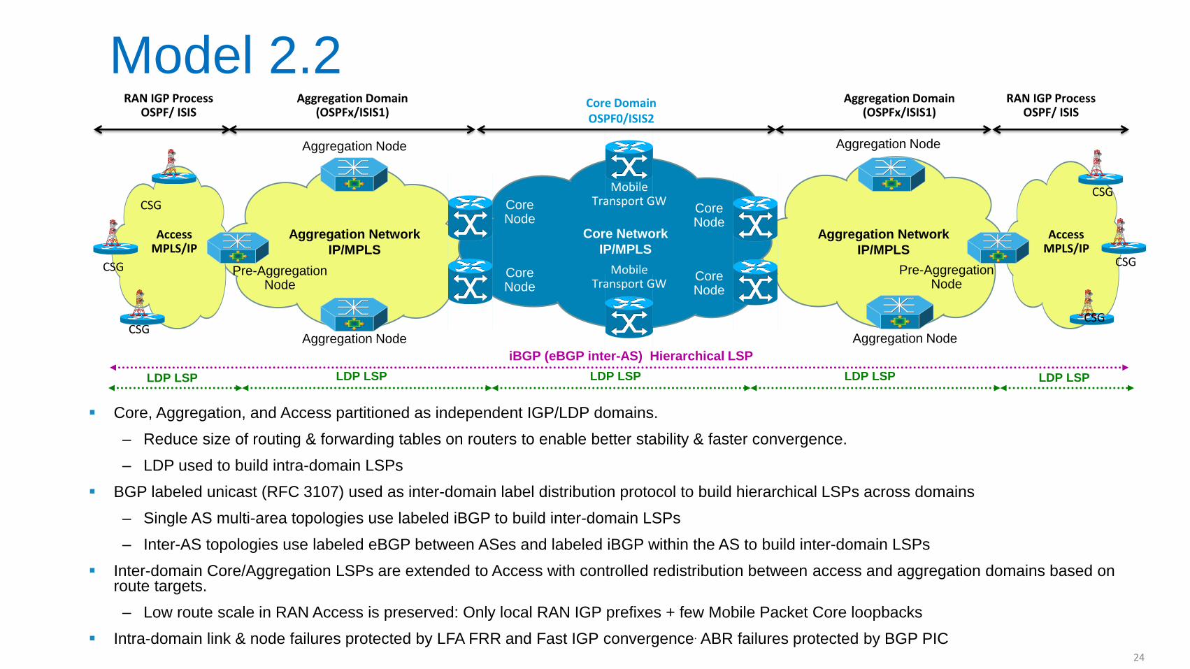
Model 2.2
Core, Aggregation, and Access partitioned as independent IGP/LDP domains.
‒ Reduce size of routing & forwarding tables on routers to enable better stability & faster convergence.
‒ LDP used to build intra-domain LSPs
BGP labeled unicast (RFC 3107) used as inter-domain label distribution protocol to build hierarchical LSPs across domains
‒ Single AS multi-area topologies use labeled iBGP to build inter-domain LSPs
‒ Inter-AS topologies use labeled eBGP between ASes and labeled iBGP within the AS to build inter-domain LSPs
Inter-domain Core/Aggregation LSPs are extended to Access with controlled redistribution between access and aggregation domains based on route targets.
‒ Low route scale in RAN Access is preserved: Only local RAN IGP prefixes + few Mobile Packet Core loopbacks
Intra-domain link & node failures protected by LFA FRR and Fast IGP convergence. ABR failures protected by BGP PIC
Access MPLS/IP
Access MPLS/IP
Core
Core
Core
Core
Core Node
Core Node
Core Node
Core Node
Core Network
IP/MPLS
Aggregation Network
IP/MPLS
Aggregation Node
Pre-Aggregation Node
Aggregation Network
IP/MPLS
Core Node
Aggregation Node
Aggregation Node
Aggregation Node
Core Node
Core Node
Core Node
Mobile Transport GW
Mobile Transport GW
Pre-Aggregation Node
CSG
CSG
CSG CSG
CSG
CSG
RAN IGP Process OSPF/ ISIS
Aggregation Domain (OSPFx/ISIS1)
Core Domain OSPF0/ISIS2
Aggregation Domain (OSPFx/ISIS1)
RAN IGP Process OSPF/ ISIS
LDP LSP LDP LSP LDP LSP LDP LSP LDP LSP
iBGP (eBGP inter-AS) Hierarchical LSP
24
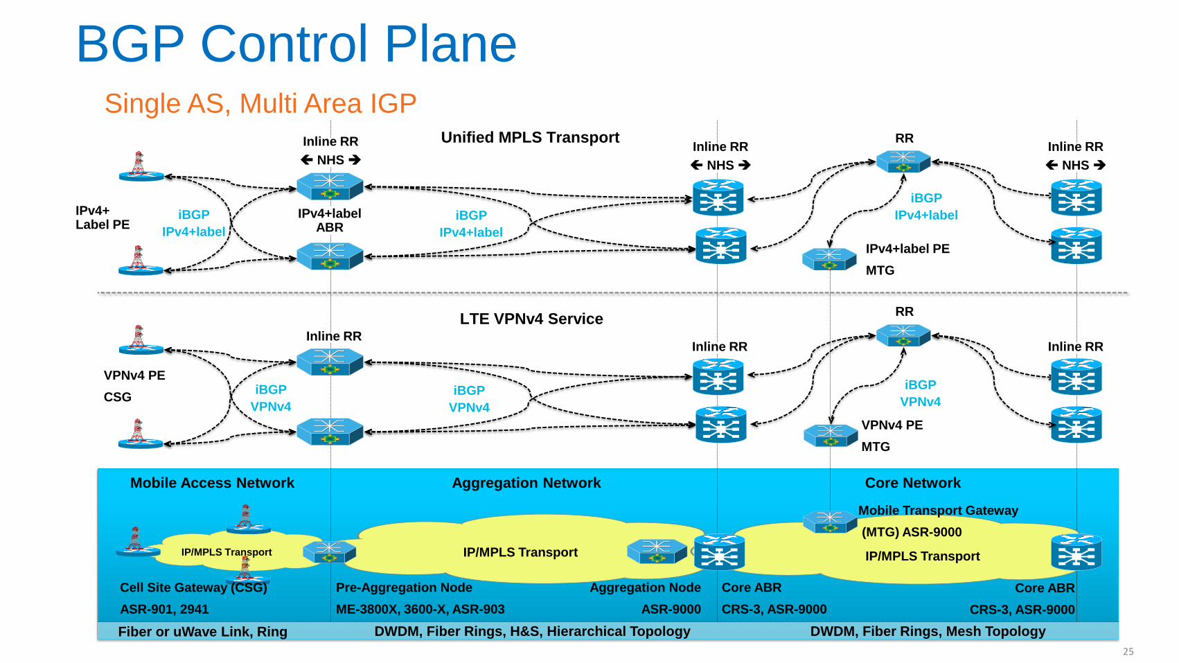
BGP Control Plane
Single AS, Multi Area IGP
Pre-Aggregation Node
ME-3800X, 3600-X, ASR-903
DWDM, Fiber Rings, Mesh Topology DWDM, Fiber Rings, H&S, Hierarchical Topology Fiber or uWave Link, Ring
Core Network Mobile Access Network Aggregation Network
Core ABR
CRS-3, ASR-9000
IP/MPLS Transport
IP/MPLS Transport
Core ABR
CRS-3, ASR-9000
Cell Site Gateway (CSG)
ASR-901, 2941
IP/MPLS Transport
LTE VPNv4 Service
Mobile Transport Gateway
(MTG) ASR-9000
Inline RR Inline RR
VPNv4 PE
CSG
Unified MPLS Transport
IPv4+label PE
MTG
Inline RR
NHS
RR
iBGP
IPv4+label
iBGP
VPNv4
Aggregation Node
ASR-9000
VPNv4 PE
MTG
RR
iBGP
IPv4+label
iBGP
VPNv4 iBGP
VPNv4
Inline RR
NHS
Inline RR
25
Inline RR
NHS
iBGP
IPv4+label
IPv4+ Label PE
IPv4+label ABR
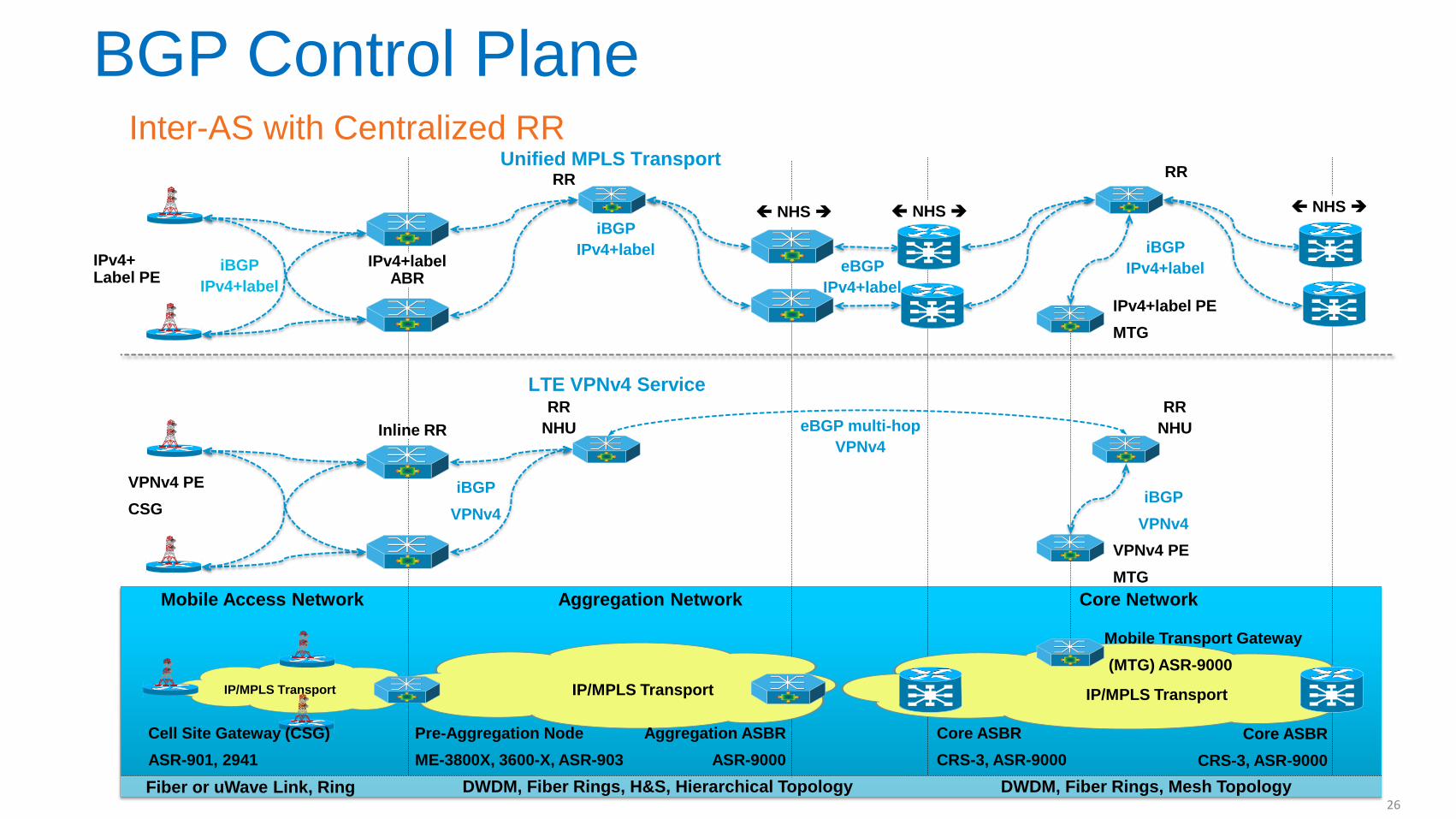
Inter-AS with Centralized RR
Pre-Aggregation Node
ME-3800X, 3600-X, ASR-903
DWDM, Fiber Rings, Mesh Topology DWDM, Fiber Rings, H&S, Hierarchical Topology Fiber or uWave Link, Ring
Core Network Mobile Access Network Aggregation Network
Core ASBR
CRS-3, ASR-9000
IP/MPLS Transport
IP/MPLS Transport
Core ASBR
CRS-3, ASR-9000
Cell Site Gateway (CSG)
ASR-901, 2941
IP/MPLS Transport
LTE VPNv4 Service
Mobile Transport Gateway
(MTG) ASR-9000
Inline RR
VPNv4 PE
CSG
Unified MPLS Transport
IPv4+label PE
MTG
IPv4+label ABR
iBGP
IPv4+label
iBGP
VPNv4
Aggregation ASBR
ASR-9000
VPNv4 PE
MTG
RR RR
eBGP
IPv4+label
RR
NHU eBGP multi-hop
VPNv4
iBGP
IPv4+label
iBGP
VPNv4
NHS NHS NHS
RR
NHU
26
iBGP
IPv4+label
IPv4+ Label PE
BGP Control Plane
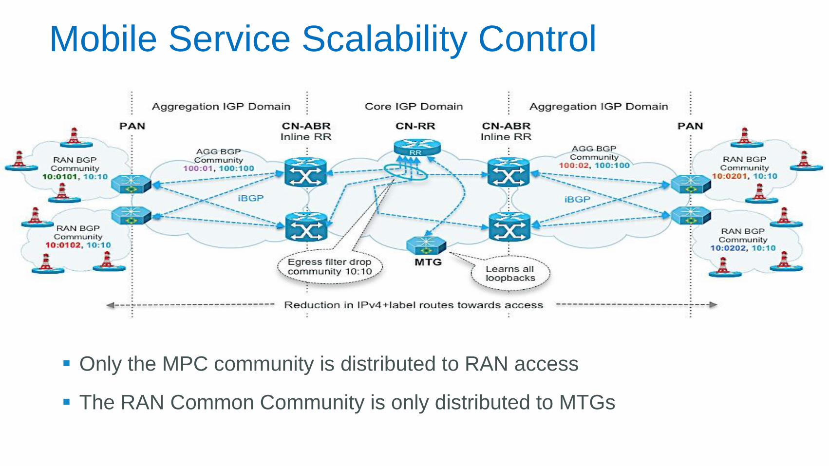
Mobile Service Scalability Control
Only the MPC community is distributed to RAN access
The RAN Common Community is only distributed to MTGs
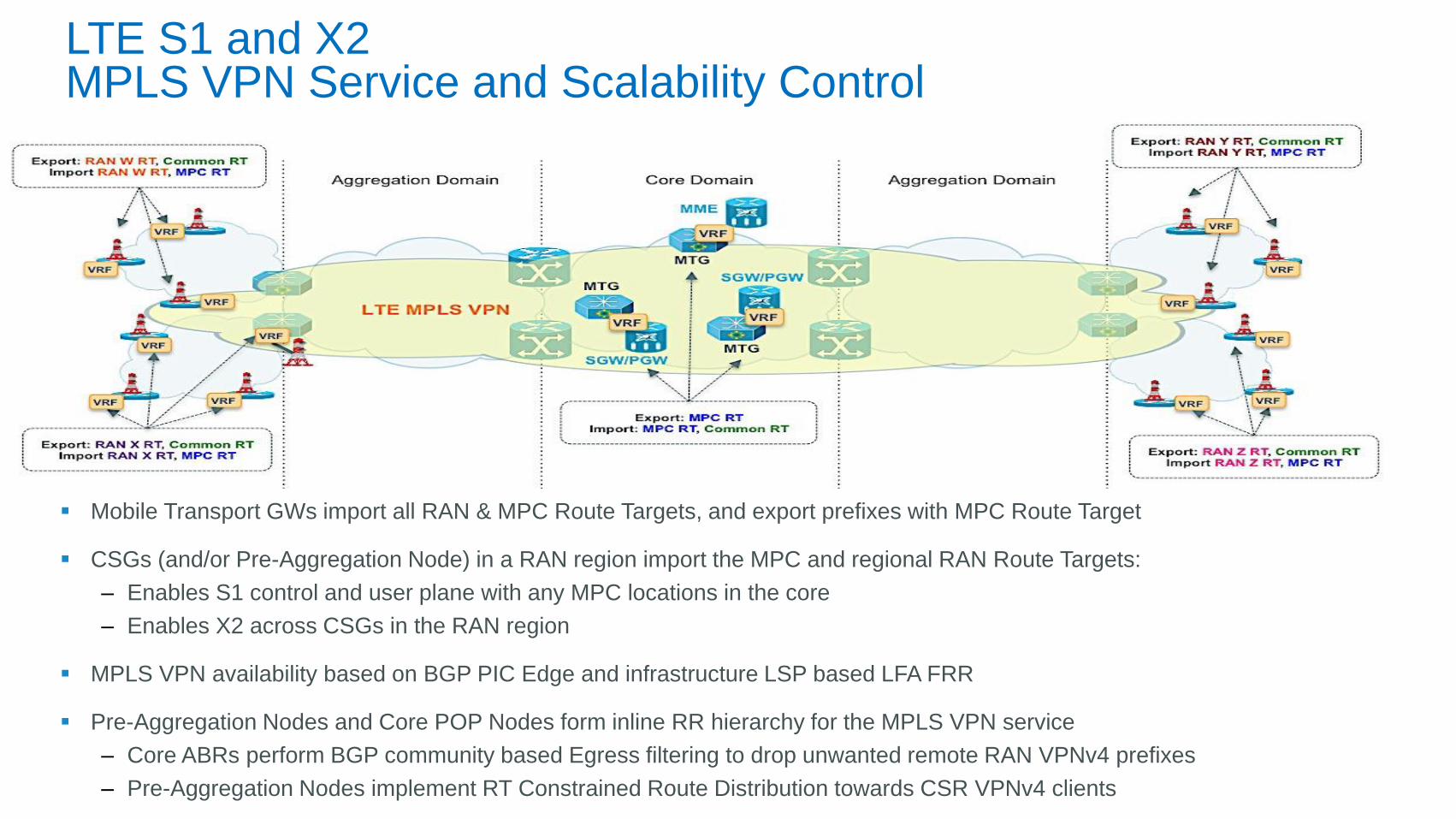
LTE S1 and X2 MPLS VPN Service and Scalability Control
Mobile Transport GWs import all RAN & MPC Route Targets, and export prefixes with MPC Route Target
CSGs (and/or Pre-Aggregation Node) in a RAN region import the MPC and regional RAN Route Targets:
‒ Enables S1 control and user plane with any MPC locations in the core
‒ Enables X2 across CSGs in the RAN region
MPLS VPN availability based on BGP PIC Edge and infrastructure LSP based LFA FRR
Pre-Aggregation Nodes and Core POP Nodes form inline RR hierarchy for the MPLS VPN service
‒ Core ABRs perform BGP community based Egress filtering to drop unwanted remote RAN VPNv4 prefixes
‒ Pre-Aggregation Nodes implement RT Constrained Route Distribution towards CSR VPNv4 clients
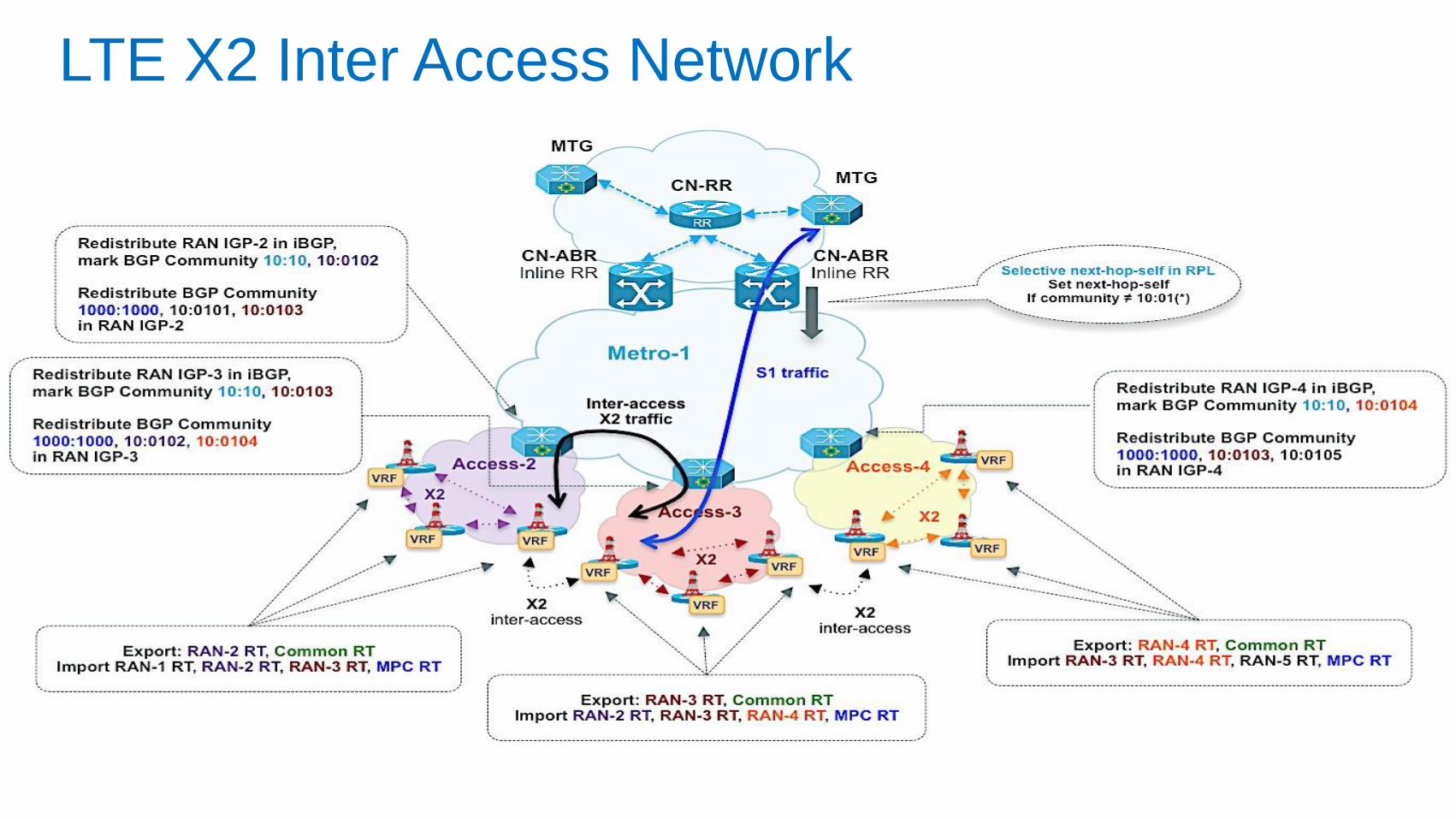
LTE X2 Inter Access Network
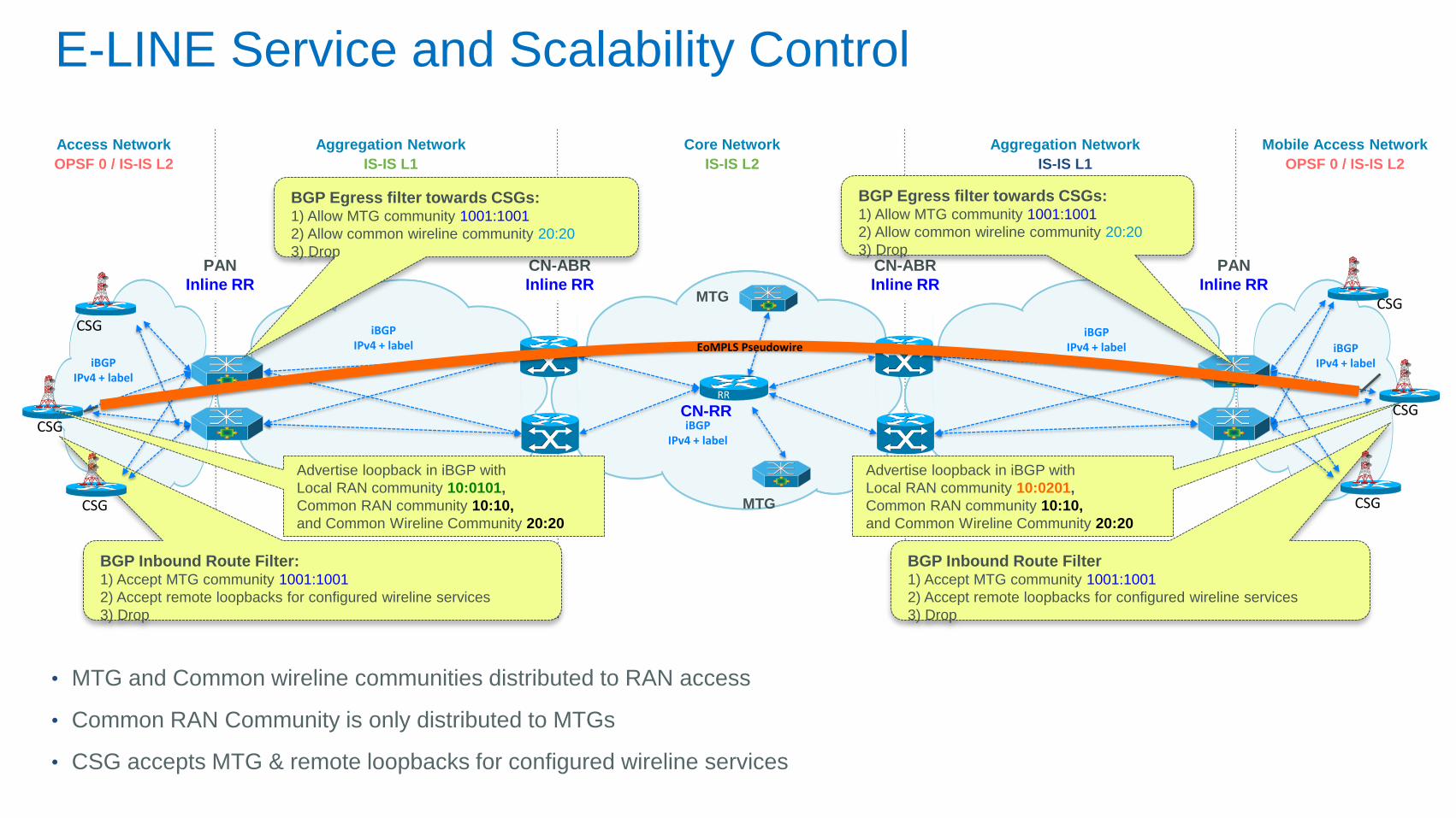
BGP Inbound Route Filter 1) Accept MTG community 1001:1001
2) Accept remote loopbacks for configured wireline services
3) Drop
BGP Inbound Route Filter: 1) Accept MTG community 1001:1001
2) Accept remote loopbacks for configured wireline services
3) Drop
CSG CSG
CN-RR RR
iBGP IPv4 + label
Core Network
IS-IS L2
Access Network
OPSF 0 / IS-IS L2
Aggregation Network
IS-IS L1
Aggregation Network
IS-IS L1
Mobile Access Network
OPSF 0 / IS-IS L2
iBGP IPv4 + label
iBGP IPv4 + label
iBGP IPv4 + label iBGP
IPv4 + label
CN-ABR
Inline RR
CN-ABR
Inline RR
BGP Egress filter towards CSGs: 1) Allow MTG community 1001:1001
2) Allow common wireline community 20:20
3) Drop
BGP Egress filter towards CSGs: 1) Allow MTG community 1001:1001
2) Allow common wireline community 20:20
3) Drop
CSG CSG
CSG
CSG
PAN
Inline RR
PAN
Inline RR
MTG
MTG
E-LINE Service and Scalability Control
EoMPLS Pseudowire
Advertise loopback in iBGP with
Local RAN community 10:0201,
Common RAN community 10:10,
and Common Wireline Community 20:20
Advertise loopback in iBGP with
Local RAN community 10:0101,
Common RAN community 10:10,
and Common Wireline Community 20:20
• MTG and Common wireline communities distributed to RAN access
• Common RAN Community is only distributed to MTGs
• CSG accepts MTG & remote loopbacks for configured wireline services
UMMT Functional Aspects
QoS
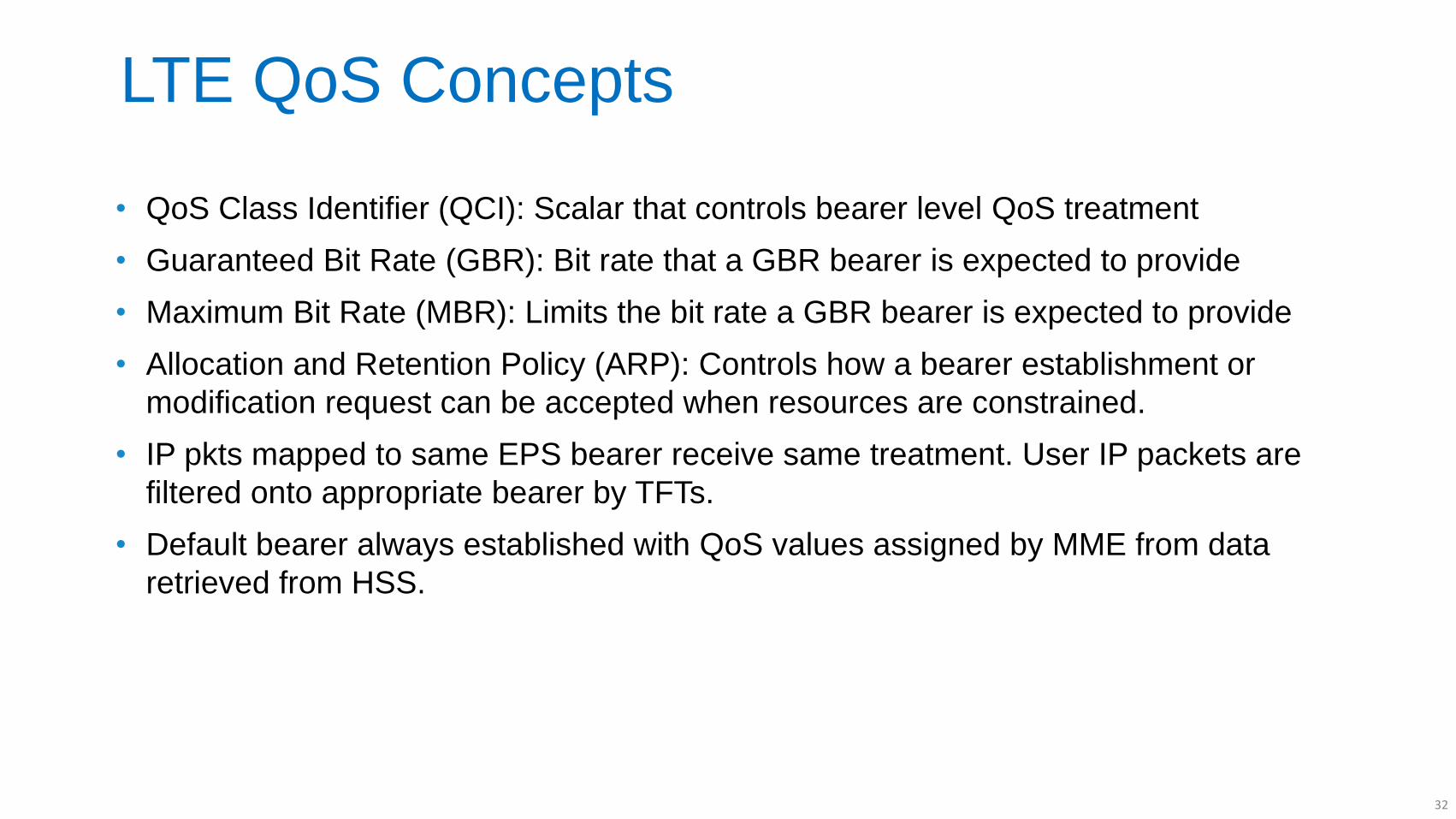
LTE QoS Concepts
• QoS Class Identifier (QCI): Scalar that controls bearer level QoS treatment
• Guaranteed Bit Rate (GBR): Bit rate that a GBR bearer is expected to provide
• Maximum Bit Rate (MBR): Limits the bit rate a GBR bearer is expected to provide
• Allocation and Retention Policy (ARP): Controls how a bearer establishment or
modification request can be accepted when resources are constrained.
• IP pkts mapped to same EPS bearer receive same treatment. User IP packets are
filtered onto appropriate bearer by TFTs.
• Default bearer always established with QoS values assigned by MME from data
retrieved from HSS.
32
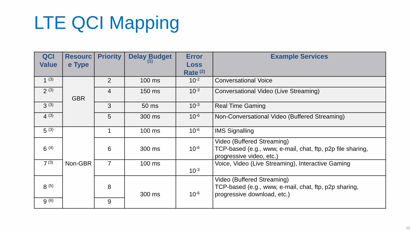
LTE QCI Mapping
QCI
Value
Resourc
e Type
Priority Delay Budget (1)
Error
Loss
Rate (2)
Example Services
1 (3) 2 100 ms 10-2 Conversational Voice
2 (3)
GBR
4 150 ms 10-3 Conversational Video (Live Streaming)
3 (3) 3 50 ms 10-3 Real Time Gaming
4 (3) 5 300 ms 10-6 Non-Conversational Video (Buffered Streaming)
5 (3) 1 100 ms 10-6 IMS Signalling
6 (4)
6
300 ms
10-6
Video (Buffered Streaming)
TCP-based (e.g., www, e-mail, chat, ftp, p2p file sharing,
progressive video, etc.)
7 (3) Non-GBR 7 100 ms
10-3
Voice, Video (Live Streaming), Interactive Gaming
8 (5)
8
300 ms
10-6
Video (Buffered Streaming)
TCP-based (e.g., www, e-mail, chat, ftp, p2p sharing,
progressive download, etc.)
9 (6) 9
33
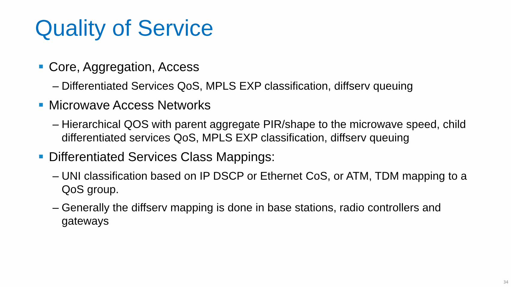
Quality of Service
Core, Aggregation, Access
‒ Differentiated Services QoS, MPLS EXP classification, diffserv queuing
Microwave Access Networks
‒ Hierarchical QOS with parent aggregate PIR/shape to the microwave speed, child
differentiated services QoS, MPLS EXP classification, diffserv queuing
Differentiated Services Class Mappings:
‒ UNI classification based on IP DSCP or Ethernet CoS, or ATM, TDM mapping to a
QoS group.
‒ Generally the diffserv mapping is done in base stations, radio controllers and
gateways
34
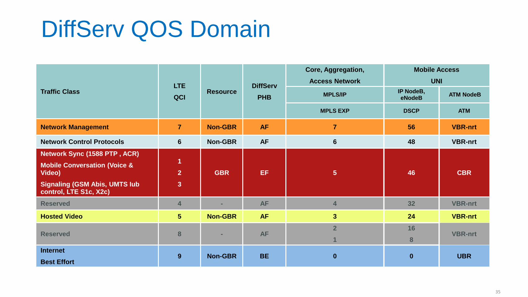
DiffServ QOS Domain
Traffic Class LTE
QCI Resource
DiffServ
PHB
Core, Aggregation,
Access Network
Mobile Access
UNI
MPLS/IP IP NodeB, eNodeB
ATM NodeB
MPLS EXP DSCP ATM
Network Management 7 Non-GBR AF 7 56 VBR-nrt
Network Control Protocols 6 Non-GBR AF 6 48 VBR-nrt
Network Sync (1588 PTP , ACR)
Mobile Conversation (Voice & Video)
Signaling (GSM Abis, UMTS Iub control, LTE S1c, X2c)
1
2
3
GBR EF 5 46 CBR
Reserved 4 - AF 4 32 VBR-nrt
Hosted Video 5 Non-GBR AF 3 24 VBR-nrt
Reserved 8 - AF 2
1
16
8 VBR-nrt
Internet
Best Effort 9 Non-GBR BE 0 0 UBR
35
UMMT Functional Aspects
Resiliency
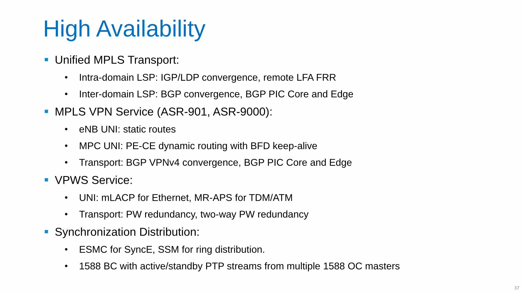
High Availability
Unified MPLS Transport:
• Intra-domain LSP: IGP/LDP convergence, remote LFA FRR
• Inter-domain LSP: BGP convergence, BGP PIC Core and Edge
MPLS VPN Service (ASR-901, ASR-9000):
• eNB UNI: static routes
• MPC UNI: PE-CE dynamic routing with BFD keep-alive
• Transport: BGP VPNv4 convergence, BGP PIC Core and Edge
VPWS Service:
• UNI: mLACP for Ethernet, MR-APS for TDM/ATM
• Transport: PW redundancy, two-way PW redundancy
Synchronization Distribution:
• ESMC for SyncE, SSM for ring distribution.
• 1588 BC with active/standby PTP streams from multiple 1588 OC masters
37
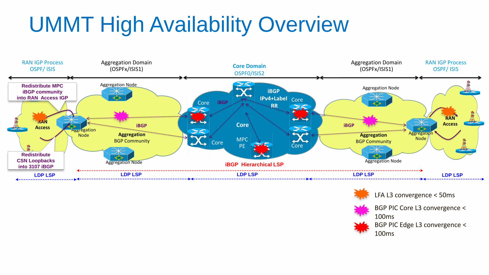
UMMT High Availability Overview
Aggregation Node
Aggregation Node
Aggregation Node
Aggregation Node
Aggregation Node
Aggregation Node
RAN IGP Process OSPF/ ISIS
Core
Core
Core
Core
LDP LSP LDP LSP LDP LSP LDP LSP LDP LSP
iBGP Hierarchical LSP
Aggregation Domain (OSPFx/ISIS1)
RAN Access
Core Domain OSPF0/ISIS2
iBGP
Aggregation BGP Community
iBGP
Aggregation BGP Community
iBGP
iBGP IPv4+Label
RR
Aggregation Domain (OSPFx/ISIS1)
RAN IGP Process OSPF/ ISIS
RAN Access Core
Redistribute MPC
iBGP community
into RAN Access IGP
Redistribute
CSN Loopbacks
into 3107 iBGP
MPC PE
LFA L3 convergence < 50ms
BGP PIC Core L3 convergence < 100ms BGP PIC Edge L3 convergence < 100ms
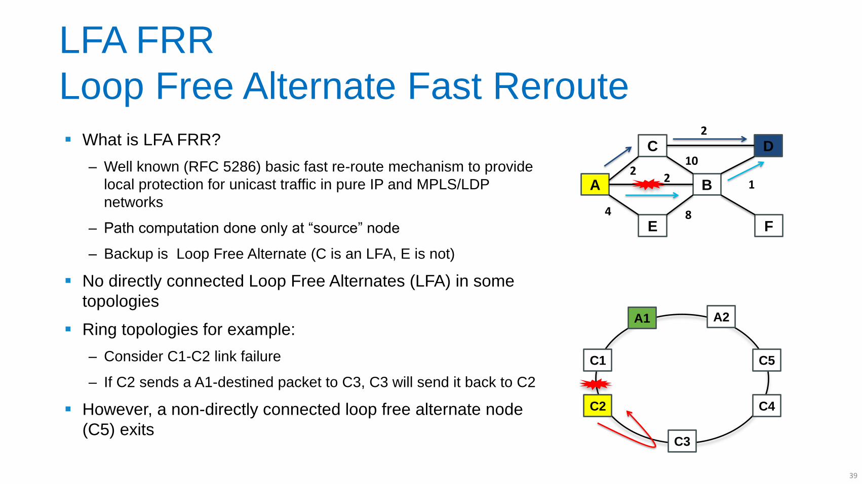
LFA FRR
Loop Free Alternate Fast Reroute
What is LFA FRR?
‒ Well known (RFC 5286) basic fast re-route mechanism to provide
local protection for unicast traffic in pure IP and MPLS/LDP
networks
‒ Path computation done only at “source” node
‒ Backup is Loop Free Alternate (C is an LFA, E is not)
No directly connected Loop Free Alternates (LFA) in some
topologies
Ring topologies for example:
‒ Consider C1-C2 link failure
‒ If C2 sends a A1-destined packet to C3, C3 will send it back to C2
However, a non-directly connected loop free alternate node
(C5) exits
A
C
E
B
D
F
2 2
10
2
1
8 4
C1
C3
C5
A2 A1
C2 C4
39
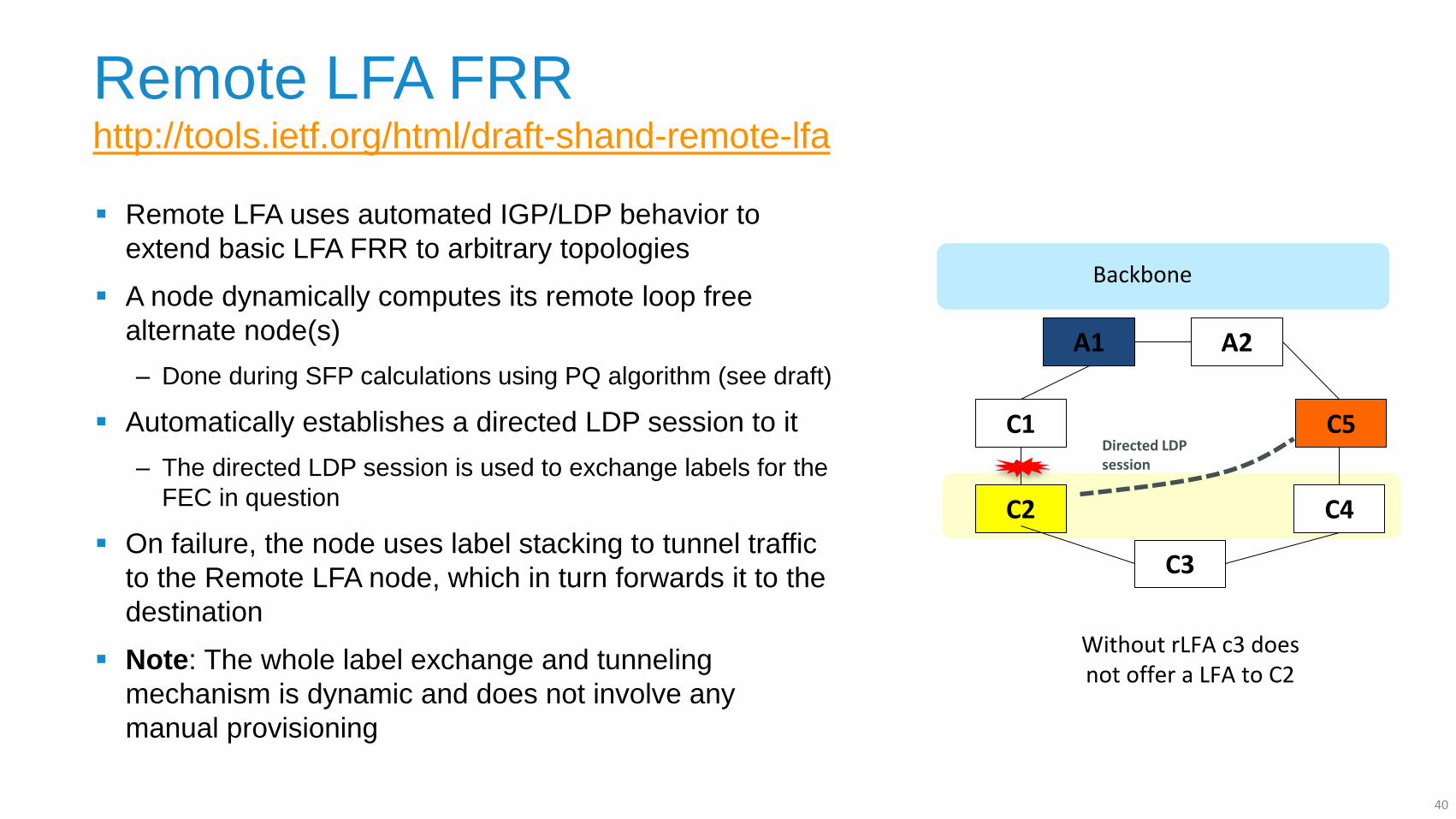
Remote LFA FRR http://tools.ietf.org/html/draft-shand-remote-lfa
Remote LFA uses automated IGP/LDP behavior to
extend basic LFA FRR to arbitrary topologies
A node dynamically computes its remote loop free
alternate node(s)
‒ Done during SFP calculations using PQ algorithm (see draft)
Automatically establishes a directed LDP session to it
‒ The directed LDP session is used to exchange labels for the
FEC in question
On failure, the node uses label stacking to tunnel traffic
to the Remote LFA node, which in turn forwards it to the
destination
Note: The whole label exchange and tunneling
mechanism is dynamic and does not involve any
manual provisioning
A1
C1
C2
C3
C4
A2
Backbone
Without rLFA c3 does not offer a LFA to C2
C5 Directed LDP session
40
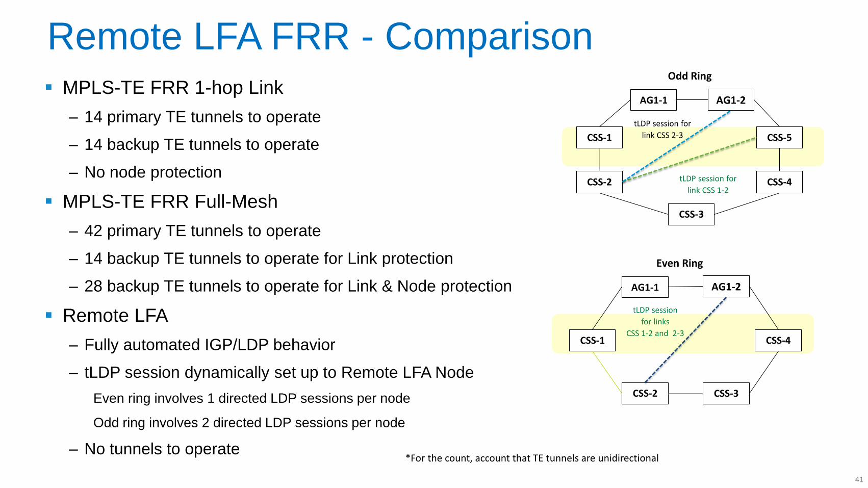
Remote LFA FRR - Comparison MPLS-TE FRR 1-hop Link
‒ 14 primary TE tunnels to operate
‒ 14 backup TE tunnels to operate
‒ No node protection
MPLS-TE FRR Full-Mesh
‒ 42 primary TE tunnels to operate
‒ 14 backup TE tunnels to operate for Link protection
‒ 28 backup TE tunnels to operate for Link & Node protection
Remote LFA
‒ Fully automated IGP/LDP behavior
‒ tLDP session dynamically set up to Remote LFA Node
Even ring involves 1 directed LDP sessions per node
Odd ring involves 2 directed LDP sessions per node
‒ No tunnels to operate
AG1-1
CSS-1
CSS-2
CSS-3
CSS-4
AG1-2
CSS-5
*For the count, account that TE tunnels are unidirectional
Odd Ring
AG1-1
CSS-1
CSS-2 CSS-3
AG1-2
CSS-4
Even Ring
tLDP session for
link CSS 2-3
tLDP session for
link CSS 1-2
tLDP session
for links
CSS 1-2 and 2-3
41
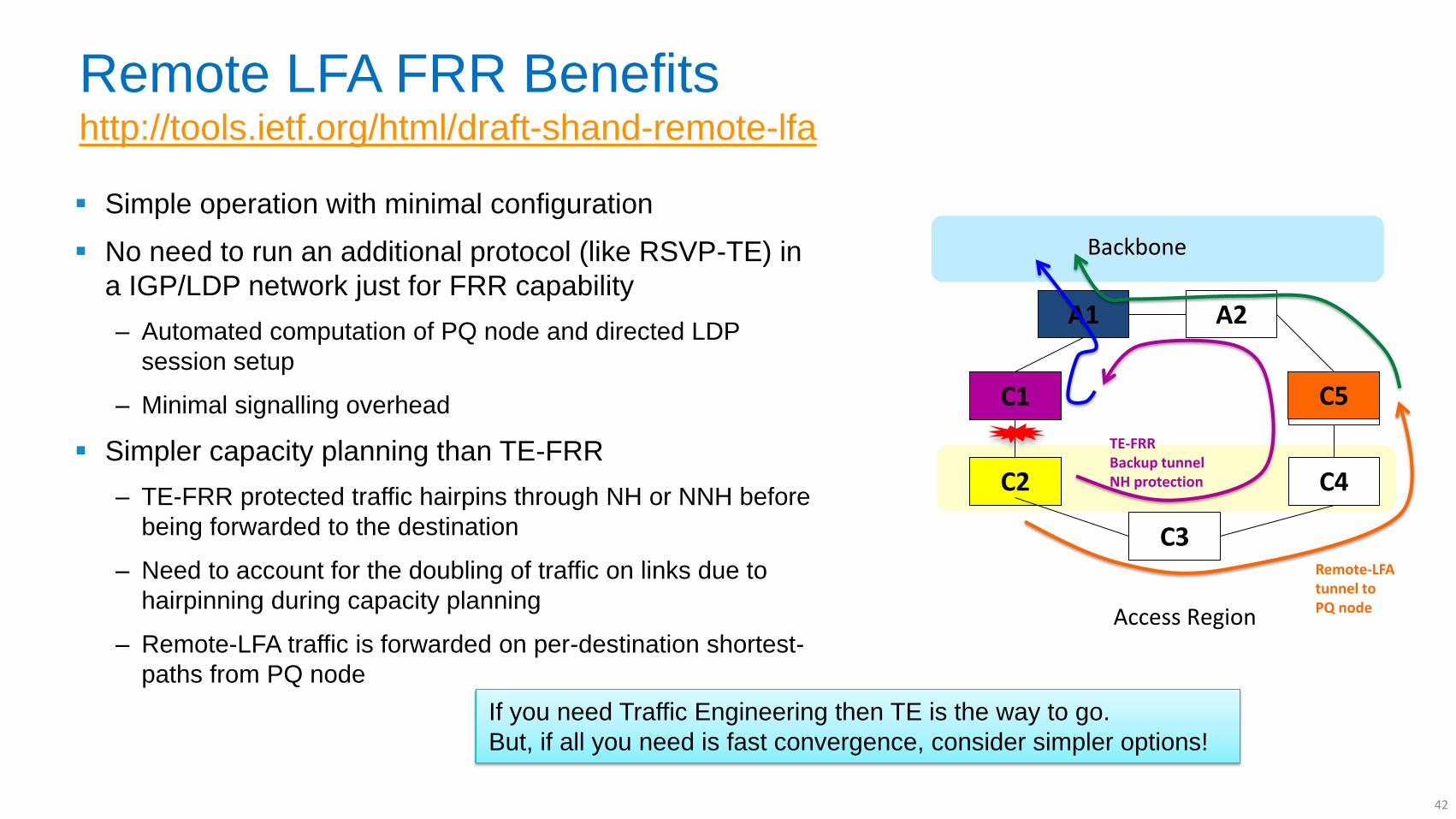
Remote LFA FRR Benefits http://tools.ietf.org/html/draft-shand-remote-lfa
Simple operation with minimal configuration
No need to run an additional protocol (like RSVP-TE) in
a IGP/LDP network just for FRR capability
‒ Automated computation of PQ node and directed LDP
session setup
‒ Minimal signalling overhead
Simpler capacity planning than TE-FRR
‒ TE-FRR protected traffic hairpins through NH or NNH before
being forwarded to the destination
‒ Need to account for the doubling of traffic on links due to
hairpinning during capacity planning
‒ Remote-LFA traffic is forwarded on per-destination shortest-
paths from PQ node
A1
C1
C2
C3
E1
C4
A2
Backbone
Access Region
C5
TE-FRR Backup tunnel NH protection
Remote-LFA tunnel to PQ node
If you need Traffic Engineering then TE is the way to go.
But, if all you need is fast convergence, consider simpler options!
42
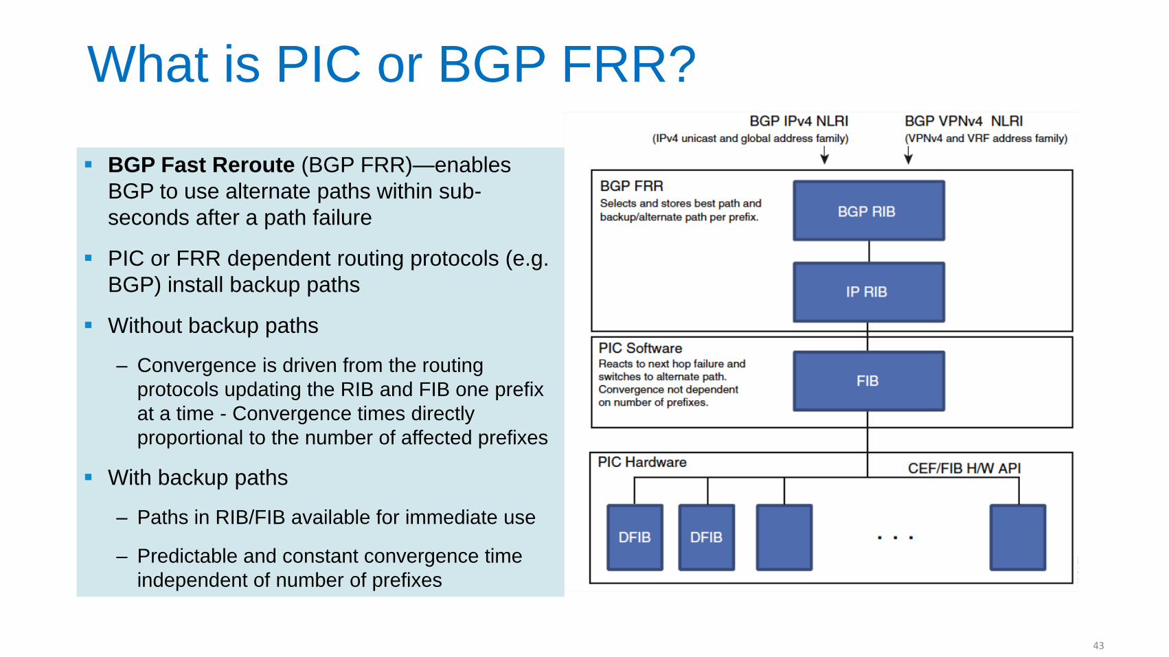
What is PIC or BGP FRR?
BGP Fast Reroute (BGP FRR)—enables
BGP to use alternate paths within sub-
seconds after a path failure
PIC or FRR dependent routing protocols (e.g.
BGP) install backup paths
Without backup paths
‒ Convergence is driven from the routing
protocols updating the RIB and FIB one prefix
at a time - Convergence times directly
proportional to the number of affected prefixes
With backup paths
‒ Paths in RIB/FIB available for immediate use
‒ Predictable and constant convergence time
independent of number of prefixes
43
P
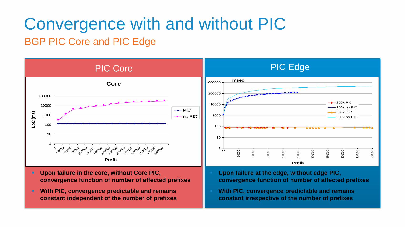
Convergence with and without PIC
Upon failure in the core, without Core PIC,
convergence function of number of affected prefixes
With PIC, convergence predictable and remains
constant independent of the number of prefixes
BGP PIC Core and PIC Edge
Core
1
10
100
1000
10000
100000
1
2500
0
5000
0
7500
0
1000
00
1250
00
1500
00
1750
00
2000
00
2250
00
2500
00
2750
00
3000
00
3250
00
3500
00
Prefix
Lo
C (
ms)
PIC
no PIC
1
10
100
1000
10000
100000
1000000
0
5000
0
1000
00
1500
00
2000
00
2500
00
3000
00
3500
00
4000
00
4500
00
5000
00
Prefix
msec
250k PIC
250k no PIC
500k PIC
500k no PIC
Upon failure at the edge, without edge PIC,
convergence function of number of affected prefixes
With PIC, convergence predictable and remains
constant irrespective of the number of prefixes
PIC Core PIC Edge
44
UMMT Functional Aspects
OAM and PM
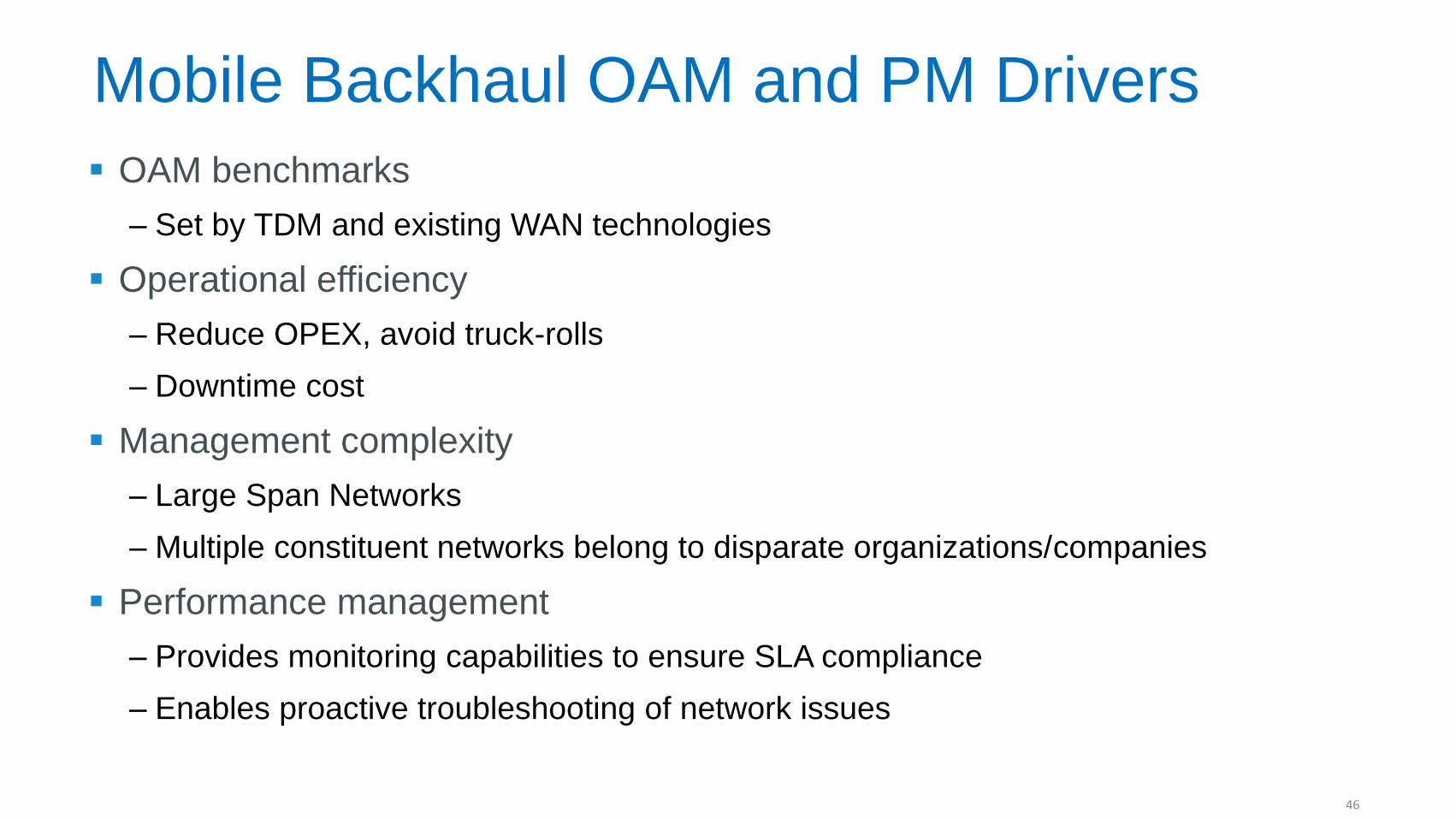
Mobile Backhaul OAM and PM Drivers
OAM benchmarks
‒ Set by TDM and existing WAN technologies
Operational efficiency
‒ Reduce OPEX, avoid truck-rolls
‒ Downtime cost
Management complexity
‒ Large Span Networks
‒ Multiple constituent networks belong to disparate organizations/companies
Performance management
‒ Provides monitoring capabilities to ensure SLA compliance
‒ Enables proactive troubleshooting of network issues
46
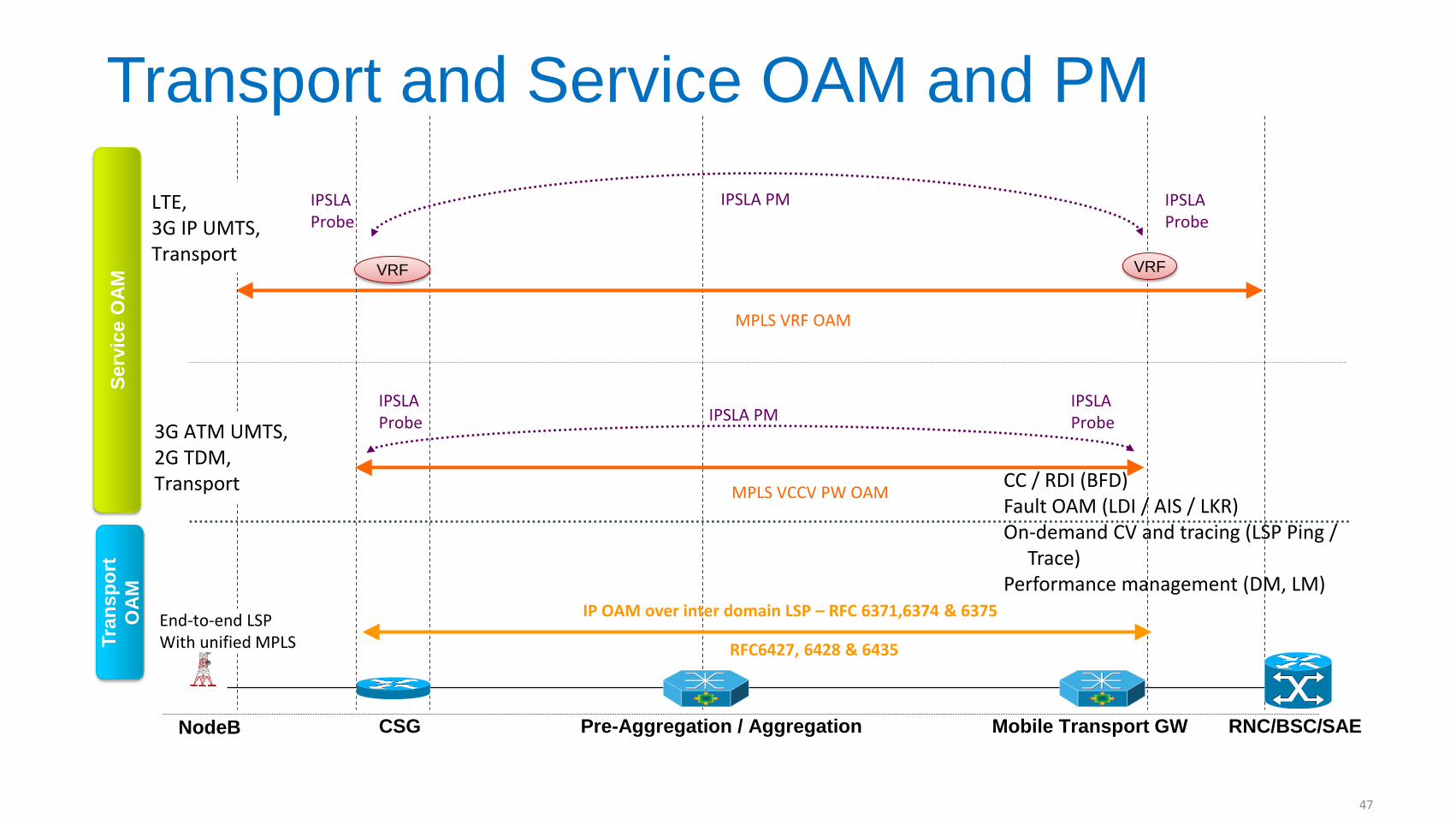
Transport and Service OAM and PM
RNC/BSC/SAE CSG Mobile Transport GW Pre-Aggregation / Aggregation
MPLS VRF OAM
IPSLA Probe
NodeB
IPSLA Probe
IPSLA PM
IP OAM over inter domain LSP – RFC 6371,6374 & 6375
MPLS VCCV PW OAM
IPSLA Probe
IPSLA Probe IPSLA PM
VRF VRF
LTE, 3G IP UMTS, Transport
3G ATM UMTS, 2G TDM, Transport
End-to-end LSP With unified MPLS RFC6427, 6428 & 6435
CC / RDI (BFD) Fault OAM (LDI / AIS / LKR) On-demand CV and tracing (LSP Ping /
Trace) Performance management (DM, LM)
Tra
ns
po
rt
OA
M
Se
rvic
e O
AM
47
UMMT Functional Aspects
Synchronization Distribution
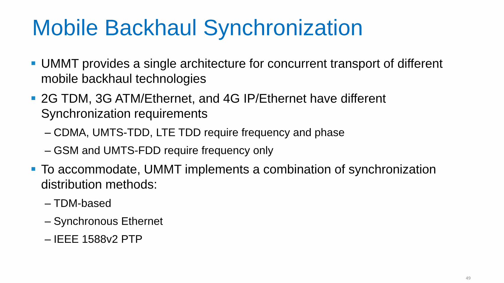
Mobile Backhaul Synchronization
UMMT provides a single architecture for concurrent transport of different
mobile backhaul technologies
2G TDM, 3G ATM/Ethernet, and 4G IP/Ethernet have different
Synchronization requirements
‒ CDMA, UMTS-TDD, LTE TDD require frequency and phase
‒ GSM and UMTS-FDD require frequency only
To accommodate, UMMT implements a combination of synchronization
distribution methods:
‒ TDM-based
‒ Synchronous Ethernet
‒ IEEE 1588v2 PTP
49
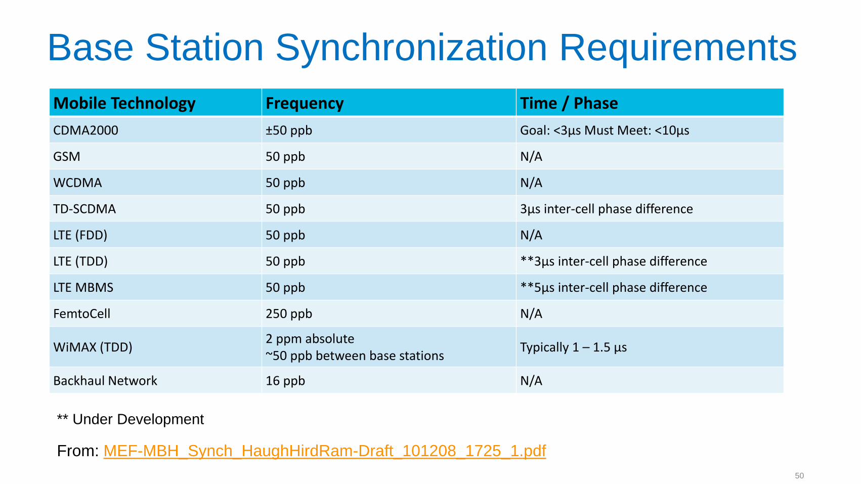
Base Station Synchronization Requirements
Mobile Technology Frequency Time / Phase
CDMA2000 ±50 ppb Goal: <3µs Must Meet: <10µs
GSM 50 ppb N/A
WCDMA 50 ppb N/A
TD-SCDMA 50 ppb 3µs inter-cell phase difference
LTE (FDD) 50 ppb N/A
LTE (TDD) 50 ppb **3µs inter-cell phase difference
LTE MBMS 50 ppb **5µs inter-cell phase difference
FemtoCell 250 ppb N/A
WiMAX (TDD) 2 ppm absolute ~50 ppb between base stations
Typically 1 – 1.5 µs
Backhaul Network 16 ppb N/A
From: MEF-MBH_Synch_HaughHirdRam-Draft_101208_1725_1.pdf
** Under Development
50
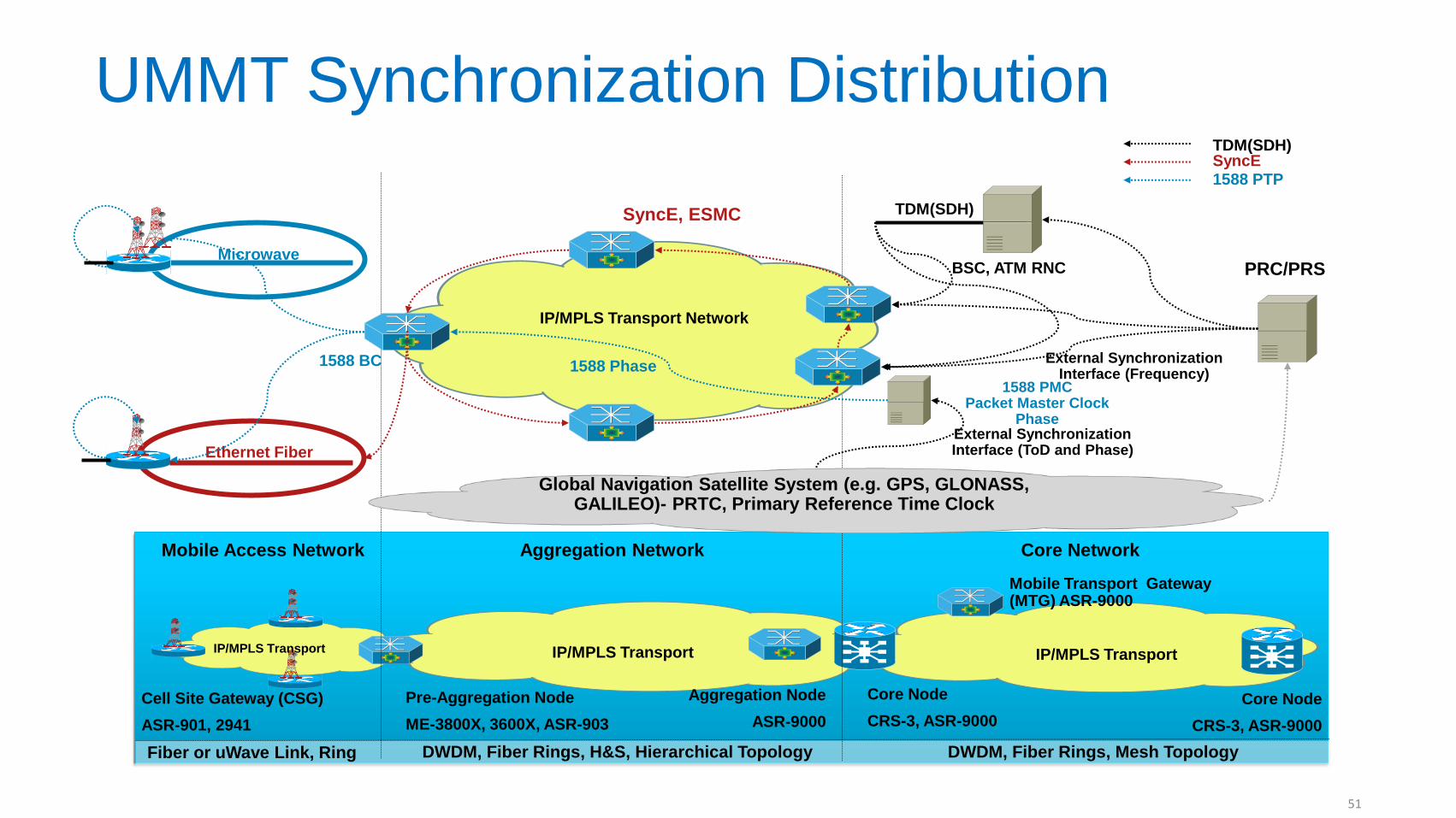
UMMT Synchronization Distribution
Pre-Aggregation Node
ME-3800X, 3600X, ASR-903
DWDM, Fiber Rings, Mesh Topology DWDM, Fiber Rings, H&S, Hierarchical Topology Fiber or uWave Link, Ring
Core Network Mobile Access Network Aggregation Network
Core Node
CRS-3, ASR-9000
IP/MPLS Transport
IP/MPLS Transport
Core Node
CRS-3, ASR-9000
Cell Site Gateway (CSG)
ASR-901, 2941
IP/MPLS Transport
Mobile Transport Gateway (MTG) ASR-9000
Aggregation Node
ASR-9000
Mobile Packet Core Network Mobile Aggregation Network
IP/MPLS Transport Network
BSC, ATM RNC
Ethernet Fiber
Microwave
SyncE, ESMC
1588 BC
PRC/PRS
External Synchronization Interface (Frequency)
Global Navigation Satellite System (e.g. GPS, GLONASS, GALILEO)- PRTC, Primary Reference Time Clock
TDM(SDH)
1588 PMC Packet Master Clock
Phase External Synchronization Interface (ToD and Phase)
1588 Phase
TDM(SDH) SyncE 1588 PTP
51
UMMT Functional Aspects
Security
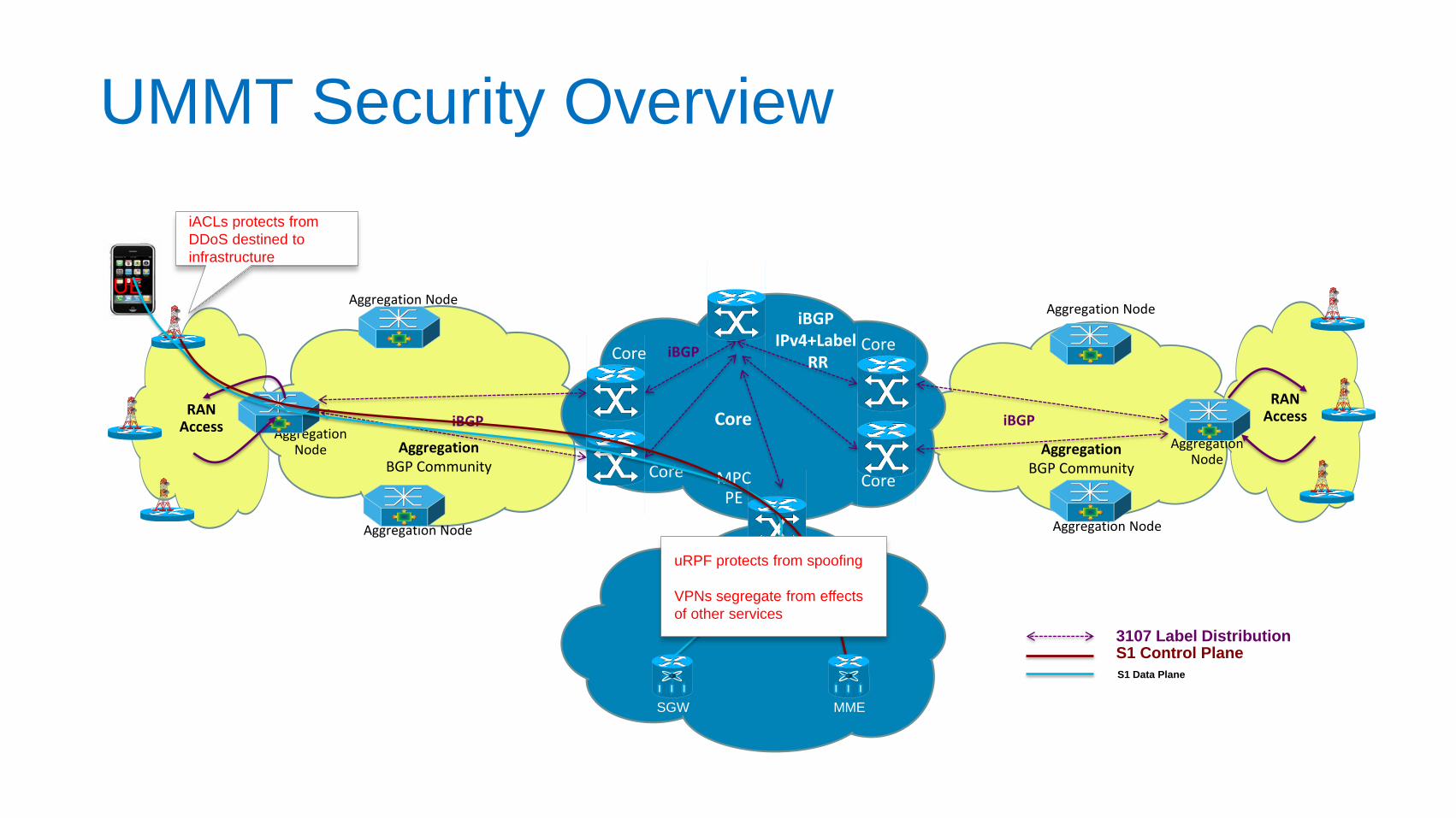
UMMT Security Overview
Aggregation Node
Aggregation Node
Aggregation Node
Aggregation Node
Aggregation Node
Aggregation Node
Core
Core
Core
Core
RAN Access iBGP
Aggregation BGP Community
iBGP
Aggregation BGP Community
iBGP
iBGP IPv4+Label
RR
RAN Access Core
iACLs protects from
DDoS destined to
infrastructure
MPC PE
UE
3107 Label Distribution S1 Control Plane
S1 Data Plane
uRPF protects from spoofing
VPNs segregate from effects
of other services
SGW MME
53
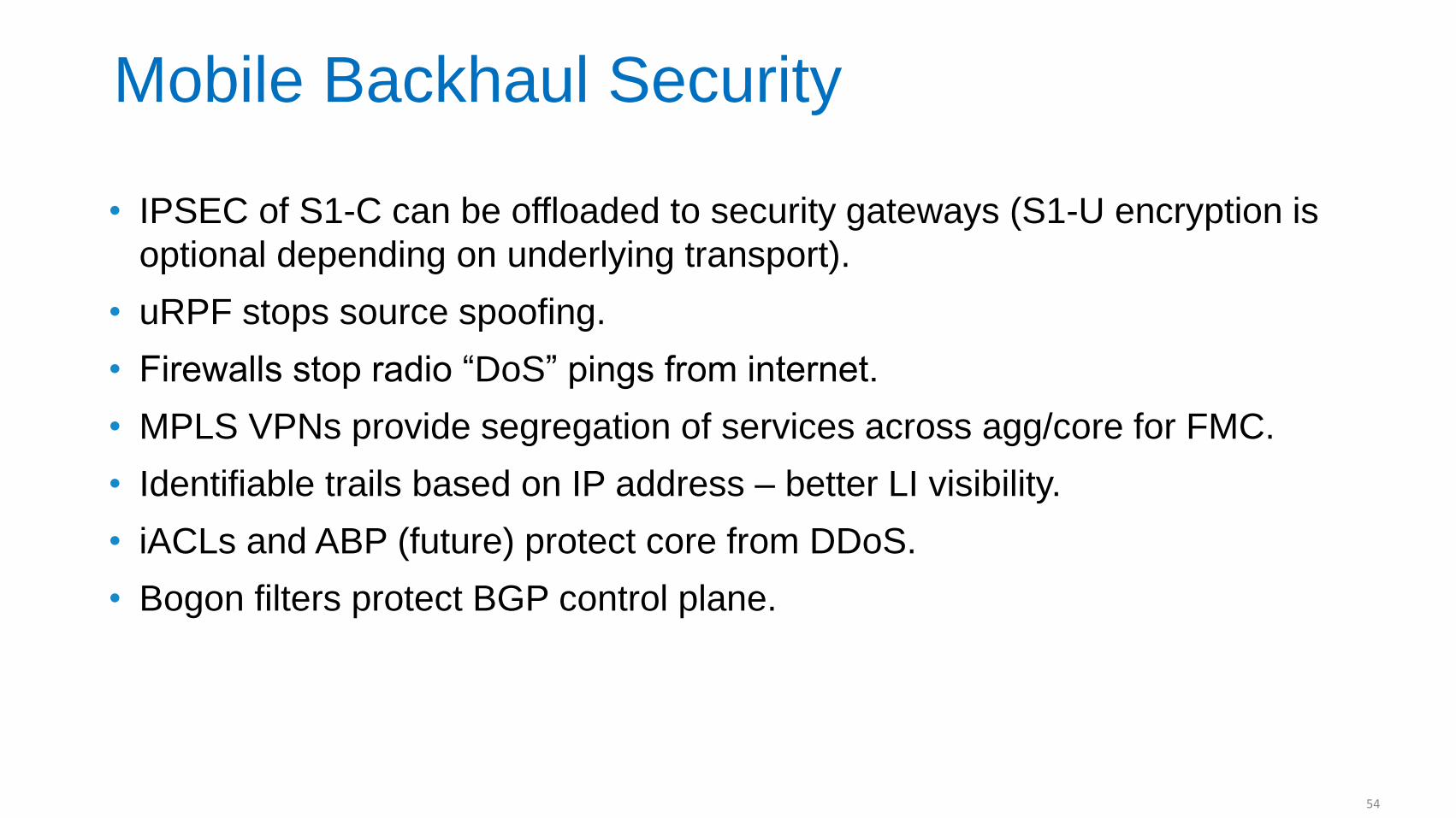
Mobile Backhaul Security
• IPSEC of S1-C can be offloaded to security gateways (S1-U encryption is
optional depending on underlying transport).
• uRPF stops source spoofing.
• Firewalls stop radio “DoS” pings from internet.
• MPLS VPNs provide segregation of services across agg/core for FMC.
• Identifiable trails based on IP address – better LI visibility.
• iACLs and ABP (future) protect core from DDoS.
• Bogon filters protect BGP control plane.
54
SDN Perspectives
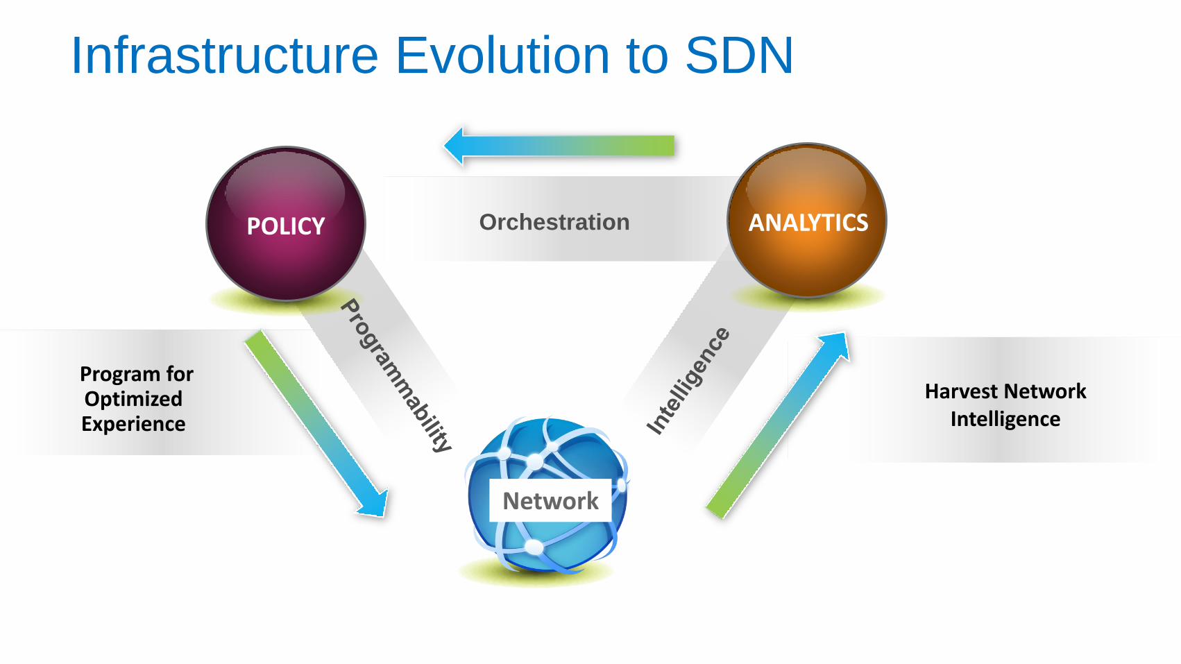
Infrastructure Evolution to SDN
POLICY ANALYTICS Orchestration
Harvest Network Intelligence
Program for Optimized Experience
Network
Traditional Control Plane Architecture (Distributed)
SDN Control Plane Architecture (Centralized)
OpenFlow
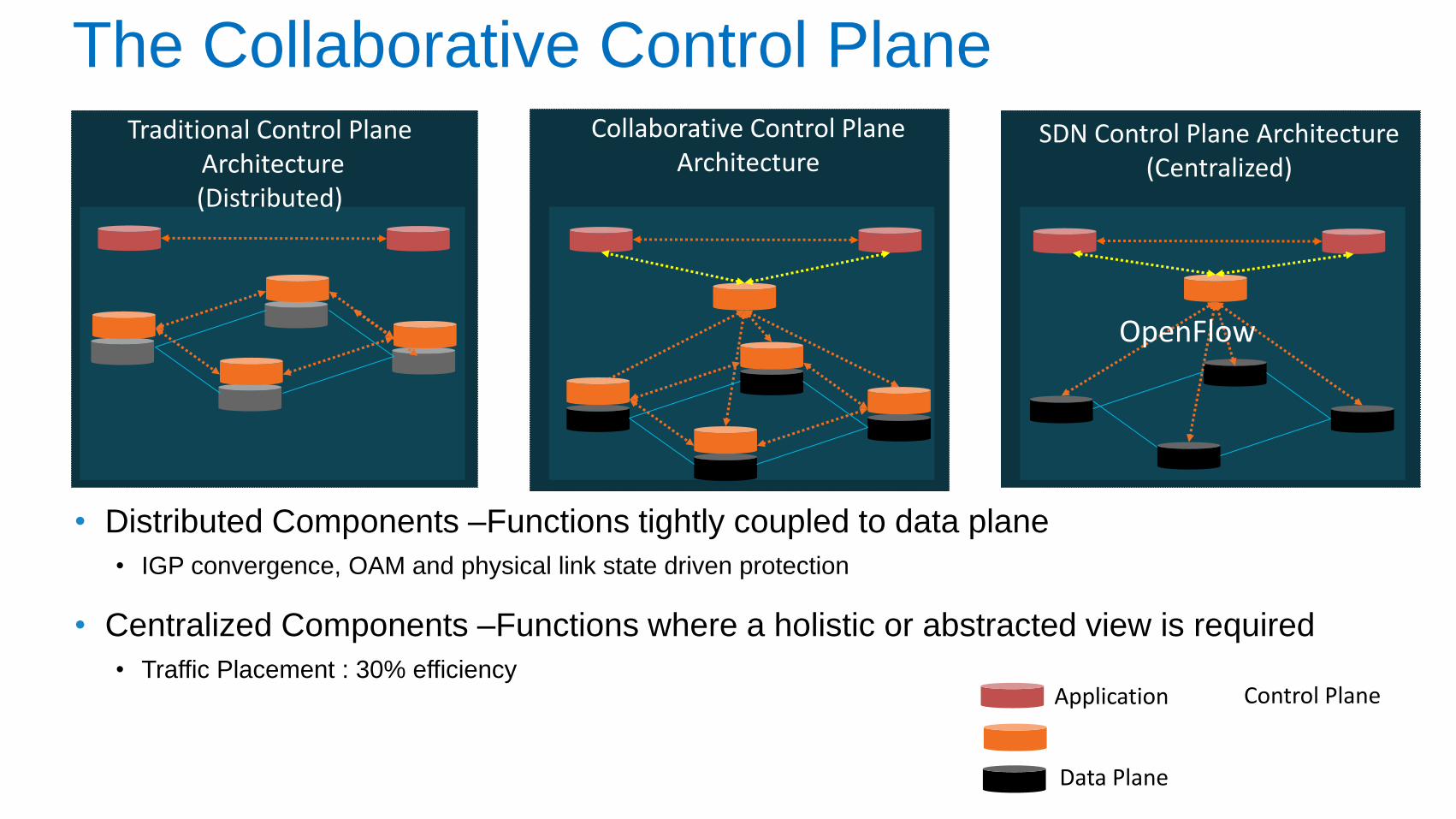
The Collaborative Control Plane
• Distributed Components –Functions tightly coupled to data plane
• IGP convergence, OAM and physical link state driven protection
• Centralized Components –Functions where a holistic or abstracted view is required
• Traffic Placement : 30% efficiency
Collaborative Control Plane Architecture
Control Plane Application
Data Plane
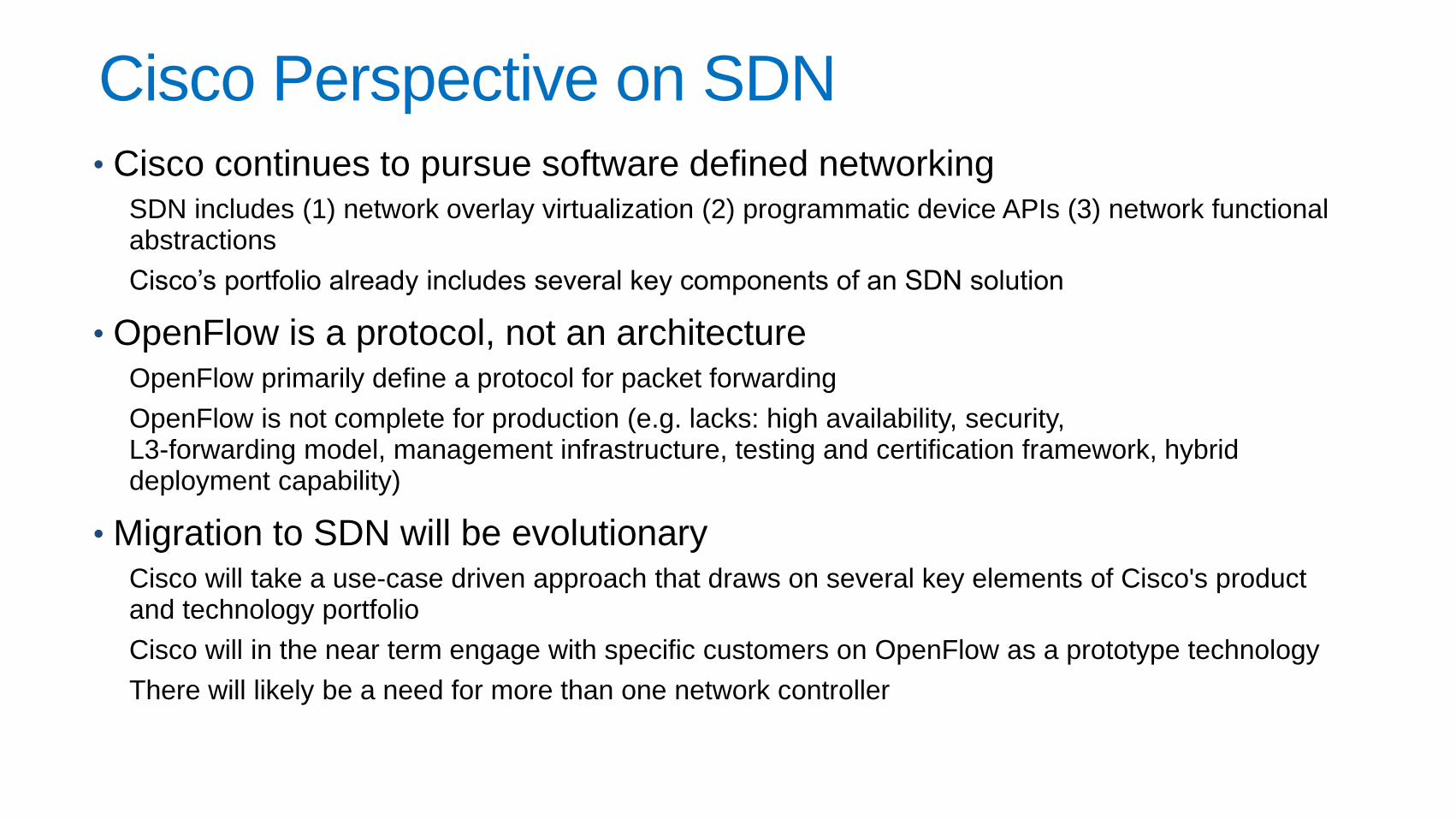
Cisco Perspective on SDN • Cisco continues to pursue software defined networking
SDN includes (1) network overlay virtualization (2) programmatic device APIs (3) network functional abstractions
Cisco’s portfolio already includes several key components of an SDN solution
• OpenFlow is a protocol, not an architecture OpenFlow primarily define a protocol for packet forwarding
OpenFlow is not complete for production (e.g. lacks: high availability, security, L3-forwarding model, management infrastructure, testing and certification framework, hybrid deployment capability)
• Migration to SDN will be evolutionary Cisco will take a use-case driven approach that draws on several key elements of Cisco's product and technology portfolio
Cisco will in the near term engage with specific customers on OpenFlow as a prototype technology
There will likely be a need for more than one network controller
UMMT Summary
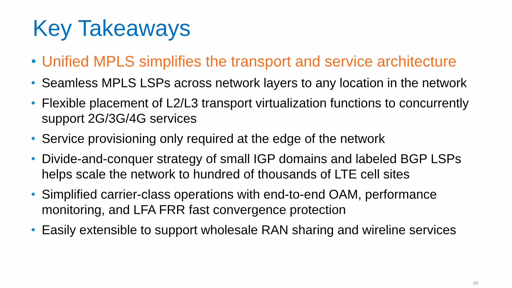
Key Takeaways
• Unified MPLS simplifies the transport and service architecture
• Seamless MPLS LSPs across network layers to any location in the network
• Flexible placement of L2/L3 transport virtualization functions to concurrently
support 2G/3G/4G services
• Service provisioning only required at the edge of the network
• Divide-and-conquer strategy of small IGP domains and labeled BGP LSPs
helps scale the network to hundred of thousands of LTE cell sites
• Simplified carrier-class operations with end-to-end OAM, performance
monitoring, and LFA FRR fast convergence protection
• Easily extensible to support wholesale RAN sharing and wireline services
60
For More Information
Email: [email protected]
Cisco SP Mobility Community:
https://communities.cisco.com/community/solutions/sp/mobility
‒ The UMMT Design Guides mentioned in this presentation can be found at the SP
Mobility Community
61
Complete Your Paper
“Session Evaluation”
Give us your feedback and you could win 1 of 2 fabulous prizes in a random draw.
Complete and return your paper
evaluation form to the room attendant as you leave this session.
Winners will be announced today.
You must be present to win!
..visit them at BOOTH# 100
© 2012 Cisco and/or its affiliates. All rights reserved. BRKSPM-3400 Cisco Public