
UNIFIED FACILITIES CRITERIA (UFC) - WBDG | … · UNIFIED FACILITIES CRITERIA (UFC) ... (Preparing...
114
UFC 4-730-10 15 June 2006 UNIFIED FACILITIES CRITERIA (UFC) FIRE STATIONS APPROVED FOR PUBLIC RELEASE; DISTRIBUTION UNLIMITED
Transcript of UNIFIED FACILITIES CRITERIA (UFC) - WBDG | … · UNIFIED FACILITIES CRITERIA (UFC) ... (Preparing...

UFC 4-730-10 15 June 2006
UNIFIED FACILITIES CRITERIA (UFC)
FIRE STATIONS
APPROVED FOR PUBLIC RELEASE; DISTRIBUTION UNLIMITED
UFC 4-730-10 15 June 2006
UNIFIED FACILITIES CRITERIA (UFC)
FIRE STATIONS
Any copyrighted material included in this UFC is identified at its point of use. Use of the copyrighted material apart from this UFC must have the permission of the copyright holder. U.S. ARMY CORPS OF ENGINEERS NAVAL FACILITIES ENGINEERING COMMAND (Preparing Activity) AIR FORCE CIVIL ENGINEER SUPPORT AGENCY Record of Changes (changes are indicated by \1\ ... /1/) Change No. Date Location
UFC 4-730-10 15 June 2006
FOREWORD The Unified Facilities Criteria (UFC) system is prescribed by MIL-STD 3007 and provides planning, design, construction, sustainment, restoration, and modernization criteria, and applies to the Military Departments, the Defense Agencies, and the DoD Field Activities in accordance with USD(AT&L) Memorandum dated 29 May 2002. UFC will be used for all DoD projects and work for other customers where appropriate. All construction outside of the United States is also governed by Status of Forces Agreements (SOFA), Host Nation Funded Construction Agreements (HNFA), and in some instances, Bilateral Infrastructure Agreements (BIA.) Therefore, the acquisition team must ensure compliance with the more stringent of the UFC, the SOFA, the HNFA, and the BIA, as applicable. UFC are living documents and will be periodically reviewed, updated, and made available to users as part of the Services’ responsibility for providing technical criteria for military construction. Headquarters, U.S. Army Corps of Engineers (HQUSACE), Naval Facilities Engineering Command (NAVFAC), and Air Force Civil Engineer Support Agency (AFCESA) are responsible for administration of the UFC system. Defense agencies should contact the preparing service for document interpretation and improvements. Technical content of UFC is the responsibility of the cognizant DoD working group. Recommended changes with supporting rationale should be sent to the respective service proponent office by the following electronic form: Criteria Change Request (CCR). The form is also accessible from the Internet sites listed below. UFC are effective upon issuance and are distributed only in electronic media from the following source: • Whole Building Design Guide web site http://dod.wbdg.org/. Hard copies of UFC printed from electronic media should be checked against the current electronic version prior to use to ensure that they are current. AUTHORIZED BY: ______________________________________ DONALD L. BASHAM, P.E. Chief, Engineering and Construction U.S. Army Corps of Engineers
______________________________________DR. JAMES W WRIGHT, P.E. Chief Engineer Naval Facilities Engineering Command
______________________________________ KATHLEEN I. FERGUSON, P.E. The Deputy Civil Engineer DCS/Installations & Logistics Department of the Air Force
______________________________________Dr. GET W. MOY, P.E. Director, Installations Requirements and Management Office of the Deputy Under Secretary of Defense (Installations and Environment)

UFC 4-730-10 15 June 2006
1
UNIFIED FACILITIES CRITERIA (UFC) NEW DOCUMENT SUMMARY SHEET
Document: UFC 4-730-10 Superseding: None. Description: This UFC provides the basic requirements for Fire Stations for all three military services and is fully coordinated.
Reasons for Document: This UFC was developed to provide design requirements for upcoming MILCON projects for Fire Stations. This UFC is fully coordinated with the latest IBC and NFPA standards. It addresses any military unique issues for fire stations on military facilities and that serve the military community. Impact: This UFC identifies the basic requirements for military fire stations. This UFC will reduce the initial cost of design and reduce costs associated with redesign of facilities that do not meet minimum standards.
UFC 4-730-10 15 June 2006
i
CONTENTS CHAPTER 1 INTRODUCTION....................................................................................... 1
1-1 SCOPE. ................................................................................................................ 1 1-2 USERS OF THIS UFC.......................................................................................... 1 1-2.1 Architects and Engineers............................................................................... 1 1-2.2 Planning Personnel. ....................................................................................... 1 1-2.3 Additional Users. ............................................................................................ 1 1-3 SCOPE OF FACILITY. ......................................................................................... 2 1-3.1 Types of Stations. ........................................................................................... 2 1-3.2 Classes of Stations. ........................................................................................ 2 1-4 USERS OF FACILITY. ......................................................................................... 3 1-5 RELATED DOCUMENTS. ................................................................................... 3
CHAPTER 2 PLANNING AND LAYOUT........................................................................ 1
2-1 SIZE DETERMINANTS. ....................................................................................... 1 2-1.1 General............................................................................................................. 1 2-1.2 Needs Validation Assessment. ...................................................................... 1 2-1.3 Types of Spaces.............................................................................................. 1 2-2 SPACE PROGRAM. ............................................................................................ 4 2-2.1 Sample Worksheets. ....................................................................................... 4 2-2.2 Critical Dimensions. ....................................................................................... 4 2-2.4 Total Area. ....................................................................................................... 7 2-3 LOCATION DETERMINANTS. ............................................................................ 7 2-3.1 Access/Response Time. ................................................................................. 7 2-3.2 Size................................................................................................................... 8 2-3.3 Sustainable Design. ........................................................................................ 8 2-4 COST. .................................................................................................................. 8 2-5 LAYOUT AND ADJACENCIES. .......................................................................... 8 2-5.1 Functional Relationship Bubble Diagram. .................................................... 8 2-5.2 Illustrative Diagrams..................................................................................... 10 2-5.3 Sample Floor Plans....................................................................................... 13 2-5.4 Space Assessment. ...................................................................................... 13 2-6 ALTERATIONS TO EXISTING FACILITIES. ..................................................... 14 2-6.1 Regulatory Authorities. ................................................................................ 14 2-6.2 Other Considerations. .................................................................................. 14
CHAPTER 3 GENERAL DESIGN CRITERIA................................................................. 1
3-1 GENERAL. ........................................................................................................... 1 3-2 STRUCTURE. ...................................................................................................... 1 3-2.1 Foundation. ..................................................................................................... 1 3-2.2 Superstructure. ............................................................................................... 1 3-2.3 Materials. ......................................................................................................... 1 3-3 EXTERIOR DESIGN. ........................................................................................... 1 3-3.1 Entrance........................................................................................................... 2 3-3.2 Exterior Finishes. ............................................................................................ 2 3-4 INTERIOR DESIGN.............................................................................................. 2 3-4.1 Interior Construction. ..................................................................................... 2

UFC 4-730-10 15 June 2006
ii
3-4.2 Finishes. .......................................................................................................... 2 3-5 ACOUSTICS. ....................................................................................................... 3 3-6 SERVICES. .......................................................................................................... 3 3-6.1 Plumbing.......................................................................................................... 3 3-6.2 Heating, Ventilating, and Air Conditioning (HVAC)...................................... 3 3-6.3 Fire Protection................................................................................................. 4 3-6.4 Electrical. ......................................................................................................... 4 3-7 SITE WORK. ........................................................................................................ 5 3-7.1 Landscaping.................................................................................................... 6 3-7.2 Firefighting Vehicle Access Drives. .............................................................. 6 3-7.3 Parking and Other Access Drives. ................................................................ 6 3-7.4 General Site Lighting. ..................................................................................... 6 3-8 BARRIER-FREE DESIGN REQUIREMENTS. ..................................................... 7 3-9 ANTITERRORISM................................................................................................ 7 3-10 SUSTAINABLE DESIGN.................................................................................. 7 3-10.1 Service Specific. ............................................................................................. 8 3-10.2 Other Sustainable Design Criteria. ................................................................ 8 3-10.3 DoD Energy Budget. ....................................................................................... 9
CHAPTER 4 SPECIFIC DESIGN CRITERIA ................................................................. 1
4-1 INTRODUCTION. ................................................................................................. 1
APPENDIX A REFERENCES ........................................................................................ 1
APPENDIX B GLOSSARY ............................................................................................. 1
ACRONYMS AND ABBREVIATIONS. ........................................................................... 1
APPENDIX C SPACE PROGRAM................................................................................. 1
APPENDIX D FIGURES................................................................................................. 1
FIGURES
FIGURE 2-1. FUNCTIONAL RELATIONSHIP BUBBLE DIAGRAM............................. 10 FIGURE 2-2. ILLUSTRATIVE LAYOUT DIAGRAM A – SMALL SATELLITE............... 11 FIGURE 2-3. ILLUSTRATIVE LAYOUT DIAGRAM B – HQ/MAIN STATION .............. 12 FIGURE 2-4. ILLUSTRATIVE LAYOUT DIAGRAM C – LARGE HQ............................ 13
TABLES
TABLE 2-1. FIRE STATION PROGRAM SPACES ........................................................ 2 TABLE 2-2. COMMON TYPES OF VEHICLES AND THEIR SIZE CLASSES .............. 6 TABLE 2-3. SAMPLE STAFFING BY VEHICLE TYPE .................................................. 7 TABLE 4-1.0. APPARATUS BAY................................................................................... 1 TABLE 4-2.0. PPE GEAR STORAGE............................................................................ 3 TABLE 4-3.0. HOSE STORAGE .................................................................................... 4 TABLE 4-4.0. SCBA MAINTENANCE/COMPRESSOR ROOM ..................................... 5 TABLE 4-5.0. PROTECTIVE CLOTHING LAUNDRY .................................................... 6 TABLE 4-6.0. EQUIPMENT MAINTENANCE/WASH/DISINFECTION........................... 7
UFC 4-730-10 15 June 2006
iii
TABLE 4-7.0. EMT STORAGE AND MEDICAL STORAGE CABINET .......................... 8 TABLE 4-8.0. HAZMAT/CBRNE EQUIPMENT STORAGE............................................ 9 TABLE 4-9.0. AGENT STORAGE................................................................................ 10 TABLE 4-10.0. SPARE PPE GEAR STORAGE........................................................... 11 TABLE 4-11.1. FIRE EXTINGUISHER (NON FLIGHTLINE) MAINTENANCE AND
STORAGE ............................................................................................................. 12 TABLE 4-11.2. FIRE EXTINGUISHER (FLIGHTLINE) MAINTENANCE AND
STORAGE ............................................................................................................. 13 TABLE 4-12.0. VEHICLE MAINTENANCE BAY .......................................................... 14 TABLE 4-13.0. VEHICLE MAINTENANCE EQUIPMENT STORAGE.......................... 16 TABLE 4-14.0. DEPLOYMENT GEAR STORAGE....................................................... 17 TABLE 4-15.0. STATION OFFICER’S OFFICE/WATCH DESK .................................. 18 TABLE 4-16.0. FIRE CHIEF’S AND DEPUTY FIRE CHIEF’S OFFICES ..................... 19 TABLE 4-17.0. OFFICES ............................................................................................. 20 TABLE 4-18.0. LOBBY................................................................................................. 21 TABLE 4-19.0. DEPARTMENT TRAINING ROOM...................................................... 22 TABLE 4-20.0. TESTING/INDIVIDUAL STUDY AREA ................................................ 23 TABLE 4-21.0. DISPATCH........................................................................................... 24 TABLE 4-22.0. INFORMATION TECHNOLOGY (IT) ROOM ....................................... 26 TABLE 4-23.0. DAY/TRAINING ROOM (Including Kitchen)......................................... 27 TABLE 4-24.0. DORM ROOMS ................................................................................... 29 TABLE 4-25.0. BATHROOMS/SHOWERS/CHANGING.............................................. 30 TABLE 4-26.0. FITNESS ROOM.................................................................................. 31 TABLE 4-27.0. LAUNDRY ROOM................................................................................ 32 TABLE 4-28.0. RECREATION ROOM ......................................................................... 33 TABLE 4-29.0. VENDING ............................................................................................ 34 TABLE 4-30.0. OUTDOOR PATIO/BBQ ...................................................................... 35 TABLE 4-31.0. EOC SITUATION ROOM..................................................................... 36

UFC 4-730-10 15 June 2006
1-1
CHAPTER 1 INTRODUCTION
1-1 SCOPE.
This UFC provides guidelines for evaluating, planning, programming, and designing Fire Stations. The information in this UFC applies to the design of all new construction projects, to include additions, alterations, and renovation projects in the continental Unites States (CONUS) and outside the continental US (OCONUS). Alteration and renovation projects should update existing facilities to meet the guidance and criteria contained in this UFC within budgetary constraints. This UFC is not intended as a substitution for thorough review during design by individual Program Managers and Operations Staff in the appropriate Service.
This UFC does not apply to the design or construction of deployment, contingency, or field operating facilities.
1-2 USERS OF THIS UFC.
This UFC is intended as a source of basic architectural and engineering information for all individuals involved in the planning, design, or evaluation of Fire Stations. Note: where one Service's criteria vary from the other Services' criteria, it is noted in the text. Specific users of the UFC include the following:
1-2.1 Architects and Engineers.
Architects and Engineers (A/Es) who will provide design services under the direction of the individual Service design agencies.
1-2.2 Planning Personnel.
Planning personnel will use this UFC for programming new or replacement facilities, pre-design planning, or assessing the extent of improvements required in an existing Fire Station in order to achieve the standard established herein.
1-2.3 Additional Users.
Additional users include the following:
• Headquarters Staff and Field Operating Agencies,
• Major Command Staff/Regions,
• Installation Commanders,
• Installation Facilities Management,
• Installation Technical Proponents,
• Fire Chiefs, and

UFC 4-730-10 15 June 2006
1-2
• Wing Commanders.
1-3 SCOPE OF FACILITY.
Fire Stations support Military firefighters' mission to provide fire protection to Installation flightlines and facilities and fire prevention education and training. This UFC does not apply to deployment, contingency, or field operating facilities.
1-3.1 Types of Stations.
Functionally, there are three types of Fire Stations:
• Structural Stations provide fire protection to facilities,
• Aircraft Rescue Firefighting (ARFF) Stations provide fire protection to flightlines and aircraft, and
• Combination Structural/ARFF Stations.
1-3.1.1 To support the firefighters' mission, it is crucial that the design of all fire stations accommodate the equipment, the numerous unique functional requirements, and the safety of the firefighting personnel. Generally, the differences between Structural and ARFF stations are limited to the Apparatus Bay size criteria (see paragraph 2-2.2 for more on these differences) and the facility location determinants (see paragraph 2-3 for more on location determinants).
1-3.1.2 The Marine Corps program includes two separate organizations—one for Structural and one for ARFF. Unlike the other Services, the Marine Corps rarely combines the stations and requires separate offices for Fire Chiefs and other personnel on their Installations.
1-3.1.3 When the fire station function is part of a consolidated operations facility (fire/police/safety/etc.), the criteria in this UFC is applicable only to the fire station functions and must be applied carefully in order to integrate with other facility functions. Identify common support/administrative spaces that can be shared to improve efficiency.
1-3.2 Classes of Stations.
Irrespective of type, there are three classes of Fire Stations:
• Headquarters (or Main) stations generally house the Fire Chief and most of the general administrative functions,
• Satellite stations are located throughout the Installation to provide adequate response time coverage, as appropriate, and
• Large Headquarters stations are very large Combination stations that typically serve an entire Installation (usually without Satellite stations).
UFC 4-730-10 15 June 2006
1-3
They occur most often on Air Force Installations and are unique because of their large size.
1-3.2.1 The differences between Headquarters and Satellite stations relate only to the additional administrative functions housed in the Headquarters station. Both Headquarters and Satellite stations may be Structural, ARFF, or Combination stations.
1-3.2.2 As noted above, the Large Headquarters Station is a large Combination station that is sited to serve both a flightline and the Installation’s structures. This class of station is used most often by the Air Force, but the other Services may also have Large HQ stations. Because of their large size, these stations have some unique space requirements related to storage and other services offered by the station. See paragraph 2-2 for more information on space requirements.
1-4 USERS OF FACILITY.
Not all of these personnel will be located in every Fire Station, but generally, all of the following individuals will be present in at least one Fire Station per Installation:
• Fire Chief,
• Deputy Fire Chief,
• Assistant Chief/Shift Supervisor,
• Firefighters,
• Inspectors,
• Training Officers (may be located outside of a Fire Station),
• Fire Prevention Officers (may be located outside of a Fire Station),
• Hazardous Materials (HAZMAT)/Safety Officer,
• Logistics Officer,
• Administrative Assistant, and
• Reserve Firefighters (Generally, Air Force only.)
1-5 RELATED DOCUMENTS.
The following documents provide additional information relevant to the design of military Fire Stations:
• Department of Defense (DoD) Instruction 6055.6, DoD Fire and Emergency Services Program,
UFC 4-730-10 15 June 2006
1-4
• FA-168, Safety and Health Considerations for the Design of Fire and Emergency Medical Services Stations,
• National Fire Protection Association (NFPA) 1500, Fire Department Occupational Safety and Health Program, and
• NFPA 1581, Fire Department Infection Control Program.
Refer also to the following Service-specific related documents:
• Army. This UFC serves as the framework for the Army’s Facilities Standardization Subcommittee’s Army Standard and Standard Design for Fire Stations.
• Navy. P-80 Facility Planning.
• Air Force. USAF Fire Station Design Guide - 1997.
• Marine Corps. Marine Corps Order (MCO) P11000.11B, Marine Corps Fire Protection and Emergency Services Program and P-80 Facility Planning.

UFC 4-730-10 15 June 2006
2-1
CHAPTER 2 PLANNING AND LAYOUT
2-1 SIZE DETERMINANTS.
Several factors determine the size of the facility.
2-1.1 General.
Generally, the size of the station depends on the class of station, the number of companies housed, the number and types of vehicles housed, and any additional spaces required.
The class of station will partially drive the number of spaces required. However, depending on what is currently available on the Installation, some spaces normally reserved for Headquarters or Large HQ stations may be provided in Satellite stations. The Installation representatives, in conjunction with the program manager, must decide which spaces should be provided.
2-1.2 Needs Validation Assessment.
Conduct a Needs Validation Assessment to determine the class and required capacity in terms of personnel and vehicles of the new or renovated station.
2-1.3 Types of Spaces.
For a complete list of spaces, see Table 2-1. Fire Station functional spaces fall into three main categories:
2-1.3.1 Maintenance and Apparatus.
This includes the Apparatus Room which houses the firefighting vehicles and the supporting maintenance spaces. The maintenance spaces include both vehicle maintenance and storage and equipment maintenance and storage (fire extinguishers, self-contained breathing apparatus (SCBA), protective clothing, hoses, firefighting agents, etc.)
2-1.3.2 Administration and Training.
This includes the appropriate offices, training spaces, dispatch areas, administrative areas, etc.
2-1.3.3 Residential and Living.
This includes the on-duty firefighters’ bedrooms, toilets/showers, kitchen/dining, recreation, and “living room” areas.
2-1.3.4 Other Spaces.
Other spaces that don’t readily fit into the three categories include the following:

UFC 4-730-10 15 June 2006
2-2
Air Force Reserve Command/Air National Guard annex may provide a separate space for administration, equipment storage/maintenance, training, and testing.
Emergency Operations Center situation room, if required by Installation mission.
Host nation employee dayroom as mandated by Master Labor Contracts (MLC) or Status of Force Agreements (SOFA).
TABLE 2-1. FIRE STATION PROGRAM SPACES
Space Notes
Maintenance and Apparatus Apparatus Room/Bays Made up of bays—either single- or double-length bays. Sized
according to truck modules: See Paragraph 2-2.2.1. Personal Protective Equipment (PPE) Gear Storage
One per station.
Hose Storage One per station. SCBA Compressor Room At least one per department. SCBA Maintenance One per department. Protective Clothing Laundry One per station. Equipment Wash/Disinfection One per station. Work Room/Equipment Maintenance One per station. Vehicle Maintenance Equipment Storage
One per station. Tools and minor parts.
EMT Storage (basic first aid supplies) One per station. Medical Storage Cabinet/Locker (drugs, needles, etc.)
One per station. Lockable. This may be combined with or a sub-space of the EMT Storage Room.
HAZMAT/CBRNE Equipment Storage
One per department. (CBRNE = Chemical, Biological, Radiological, Nuclear, Explosive.)
Agent Storage At least one per department. Spare Gear Storage At least one per department. Fire Extinguisher Maintenance and Storage
One per department, as dictated by Installation mission requirements.
Flightline Fire Extinguisher Maintenance and Storage
One per department.
Vehicle Maintenance Bay Addition to Apparatus Room, as dictated by Installation mission requirements.
Vehicle Maintenance Office As dictated by Installation mission requirements if Vehicle Maintenance Bay is provided.
Reserve and Active Duty Mobility/Deployment Gear Storage
As dictated by Installation mission requirements.
Administration and Training Station Officer Office One per station. Watch Desk One per station only if no Dispatch in station and then made part of
Station Officer Office. (Receives calls from Dispatch.) Fire Chief Office One per department. Chief’s Conference Room One per department. May be a part of the Fire Chief’s Office.

UFC 4-730-10 15 June 2006
2-3
TABLE 2-1. FIRE STATION PROGRAM SPACES
Space Notes Deputy Chief Office The requirement for a Deputy Chief is driven by the size of the
department. Administrative Assistant Provided only in conjunction with Chief and Deputy Chief. Lobby Area Generally provided only in conjunction with Chief and Deputy
Chief. Assistant Chief/Shift Supervisor One per department. Assistant Chief of Fire Prevention One per department, as dictated by Installation mission
requirements. Inspector(s) Offices Several workstations per department—may be located in several
stations. EMS Office Space for EMS to complete confidential paperwork, as dictated by
Installation mission requirements. HAZMAT/Safety Office One per department. Logistics Office One workstation per department, as dictated by Installation mission
requirements. Department Training Room At least one per department (in HQ station). May be provided in
other stations, as dictated by Installation mission requirements. Training Officer Office One per department. Computer Training/testing Area One per station. Separate room or alcove. General Admin Storage One per station. Fire-only Dispatch One per department; provided only if no requirement for
Consolidated Dispatch. Dispatch receives emergency calls from the public.
Consolidated Dispatch Provided in lieu of Fire-only Dispatch. Combines fire, security, and medical dispatch functions.
Dispatch Supervisor Provided in conjunction with Consolidated Dispatch. Dispatch Bathroom Dedicated facilities close to Dispatch. Dispatch Kitchenette Dedicated facilities close to Dispatch. Information Technology (IT) Room One per station. Consider presence/size of dispatch and/or watch
room in size and location of room. Generator Space One per station. May need to be located inside as a security concern.
Residential and Living Day/Training Room One per station. Includes kitchen, training/dining, and lounge areas.
The station training area is incorporated as part of the dining portion of the Day Room.
Dorm Rooms Per station. Quantity depends on number of crews. Bathrooms/shower/changing Male and female facilities per station. Fitness Room One per station. Laundry Room One per station. Physical Therapy/sauna Addition to Fitness Room, as dictated by Installation mission
requirements. Recreation Room Addition to Day Room for noisier activities such as games, as
dictated by Installation mission requirements. Covered Outdoor Patio One per station.
Other Spaces

UFC 4-730-10 15 June 2006
2-4
TABLE 2-1. FIRE STATION PROGRAM SPACES
Space Notes EOC Situation Room Conference room, as dictated by Installation mission requirements. Reserve Firefighter Gear Air Force only. As dictated by Installation mission requirements. Reserve Offices Air Force only. Offices (two) for Fire Chief and Assistant Chief
and Training Officer, as dictated by Installation mission requirements.
2-2 SPACE PROGRAM.
The space program for Fire Stations is developed through the use of an interactive worksheet. It is completed by first entering the appropriate Service branch and then selecting the following: the type of station, the class of station, the number of companies to be housed/dorm room count, the number and class of vehicles to be housed, and the additional spaces required.
The selections vary depending on the Service Branch selected as a result of the appropriate Service exceptions. As selections are made, the program areas are calculated and summed for both the building and the site. The worksheet must be filled out in collaboration with the appropriate fire department representative(s).
This interactive worksheet is available as a downloadable Microsoft© Excel© file (within a .zip) from the Whole Building Design Guide Web site (ufc_4_730_10_FireSpaceProgram_Feb2009.zip).
2-2.1 Sample Worksheets.
Samples of the interactive worksheet may be found in Appendix C.
2-2.2 Critical Dimensions.
To understand how the numbers in the interactive worksheet are calculated, there are several critical dimensions that must be understood.
2-2.2.1 Apparatus Bays.
The apparatus bays are sized based on the class of truck to be housed. See Table 2-2 for a list of common truck types. These types have been classified as follows in order to standardize the size criteria:
• Large. These typically include structural aerial (ladder) trucks or large tanker trucks with lengths greater than 11.58 m (38 ft.). The standardized footprint (floor space occupied by the truck, not considering the space around it) is 3.05 m by 15.24 m (10 ft. by 50 ft.).
• Medium. This class covers a wide range of vehicles from structural pumper trucks and smaller tanker trucks to rescue and HAZMAT trucks.

UFC 4-730-10 15 June 2006
2-5
Medium trucks have lengths between 9.14 and 11.58 m (30 and 38 ft.). The standardized footprint is 3.05 m by 11.58 m (10 ft. by 38 ft.).
• Large ARFF (wide). All ARFF trucks are distinguished by their generally greater width and may include heavy rescue or very large tankers. Large ARFF trucks have lengths greater than 11.58 m (38 ft.). The standardized footprint is 3.66 m by 13.72 m (12 ft. by 50 ft.).
• Medium ARFF (wide). Medium ARFF trucks are also distinguished by their generally greater width. They can vary in length from about 7.01 m (23 ft.) up to 11.58 m (38 ft.), but the standardized footprint is 3.66 m by 11.58 m (12 ft. by 38 ft.).
• Small. These typically include ambulances, small rescue or HAZMAT trucks, small brush units, and command vehicles. Small trucks have lengths less than 9.14 m (30 ft.). A separate vehicle bay size class is not designated for these trucks. Depending on the actual size of the Small class truck, it may be housed in its own bay or in a bay with another truck. For example, two 6.10-m- (20-ft.-) long vehicles may be housed in a Large bay (either ARFF or not). The interactive worksheet makes a recommendation for the area of additional Apparatus Bays, as appropriate, for the quantity of Small vehicles indicated. However, this area must be carefully reviewed by the planning team to ensure it provides the correct space, accounting for the actual length of the Small vehicles anticipated and the space that may be available in other bays.
In addition to the truck footprint, the space program takes into account the space around the parked truck. This space varies depending on whether the truck is parked next to a wall or another truck. See Figures C-1.1 through C-1.4 for illustrations of these variations. The space program uses the middle-sized bay for each truck class to calculate an “average” sized bay for the given vehicle. Also see Table 4-1.0 for more information on the Apparatus Bays.

UFC 4-730-10 15 June 2006
2-6
TABLE 2-2. COMMON TYPES OF VEHICLES AND
THEIR SIZE CLASSES
Type of vehicle
Size Class of Vehicle (see Paragraph 2-2.2.1)
Structural Pumpers Medium Telesquirts Medium Aerial/Ladders Large Tankers Medium or Large
ARFF Large Water Tankers ARFF Medium ARFF Foam (vary from 5700 L (1500 gal.) up to 24,600 L (6500 gal.)
ARFF Medium or ARFF Large
Ambulance Ambulances Small
Rescue Small/Light Rescue Small Medium Rescue Medium Heavy Rescue ARFF Medium
HAZMAT HAZMAT Support/Small Small HAZMAT Squad Medium
Brush Small Brush Small Large Brush Medium
2-2.2.2 Dorm Room Counts.
The worksheet uses two methods to calculate the number of dorm rooms needed (dorm room count). First, the user enters the number of Structural companies and the number of ARFF companies, as appropriate. (If it is a Structural station, ARFF companies are not permitted and vice versa.) Based on the branch of Service selected, the worksheet will calculate the number of dorm rooms using the number of companies entered. Second, the user adds or subtracts dorm rooms to accommodate ambulance companies, rescue companies, or cross-staffing of companies. The initial number of rooms plus or minus the modified number of rooms is the Final Dorm Room count.
Dorm room counts must be coordinated with the Fire Chief. See Table 2-3 for sample staffing by vehicle type. Cross staffed (x-staffed) vehicles are staffed on an as needed basis by personnel assigned to another vehicle or vehicles. X-staffed vehicles have no dedicated staff of their own. The sample vehicle staffing numbers shown in Table 2-3 do not represent staffing authorizations.

UFC 4-730-10 15 June 2006
2-7
TABLE 2-3. SAMPLE STAFFING BY VEHICLE TYPE
Type of vehicle
Army
Navy
Air Force
Marine Corps
Structural Pumpers 4 4 4 4 Telesquirts 4 or x-staffed 4 4 4 Aerial/Ladders 4 or x-staffed 4 4 4 Tankers x-staffed 1 or x-staffed n/a 1 or x-staffed
ARFF Large Water Tankers x-staffed 1 or x-staffed 1 1 or x-staffed ARFF Foam 3 3 3 4
Ambulance Ambulances 2 or x-staffed 2 n/a 2 or x-staffed
Rescue Small/Light Rescue x-staffed 3 or x-staffed 3 3 or x-staffed Medium Rescue x-staffed 3 or x-staffed 3 3 or x-staffed Heavy Rescue x-staffed 3 or x-staffed 3 3 or x-staffed
HAZMAT HAZMAT Support/Small x-staffed x-staffed x-staffed x-staffed HAZMAT Squad x-staffed x-staffed x-staffed x-staffed
Brush Small Brush x-staffed x-staffed x-staffed x-staffed Large Brush x-staffed x-staffed x-staffed x-staffed
2-2.3 Space Data.
The data upon which the interactive worksheet is based is illustrated in Appendix C. Do not use Appendix C to develop the space program—use only the interactive worksheet.
2-2.4 Total Area.
The space program developed through the use of the interactive worksheet serves as a guideline for the Fire Station planning team and generally represents the maximum space allowed. The final space program for a new Fire Station will need to be carefully determined by Installation representatives and the appropriate Service program office guided by the criteria in this UFC.
2-3 LOCATION DETERMINANTS.
Several factors determine the most appropriate and cost-effective location for a Fire Station.
2-3.1 Access/Response Time.

UFC 4-730-10 15 June 2006
2-8
The most critical determinant for the location of a Fire Station is response time. Refer to DoD Instruction 6055.6, DoD Fire and Emergency Services Program to determine required response times. In addition to response time, consider access to the station by delivery vehicles, staff, and visitors.
Consider that direct access and response time may conflict with tightening antiterrorism (AT) criteria—ensure that trucks will not have to cross access control points to reach a target structure or flightline. See paragraph 3-9 for more information on AT requirements.
Facility site should be prominent and easily visible from the target areas (structures or flightlines).
2-3.2 Size.
Ensure adequate site space is available to accommodate the firefighting vehicular turning radii, personnel parking, visitor parking, storage requirements, and reserve vehicles (if applicable).
2-3.3 Sustainable Design.
The location of a facility can have a significant impact on achieving sustainable design rating points (see paragraph 3-10 for more information on sustainable design and sustainable rating systems). Consider issues such as brownfield redevelopment, access to public transportation, and reuse of existing paving and hardscape when selecting a site.
2-4 COST.
These facilities should be designed with the objective of achieving the lowest life cycle cost over a 30-year period. To do so, the project’s design program must adequately define the scope and performance requirements and match those needs against a budget. Conversely, the budget must adequately support an appropriate and high-quality program and the performance requirements outlined and identified in this UFC.
2-5 LAYOUT AND ADJACENCIES.
As with the location determinants, the key internal adjacencies are driven by response time. The location of the residential and living areas must accommodate quick and clear access to the Apparatus Room for response in the event of an alarm. The appropriate layout and adjacencies are illustrated through a bubble diagram and a series of illustrative layout diagrams.
In HQ/Main Stations and Large HQ Stations, consider the relationship between the administrative areas and the living areas. There may be a desire to separate these areas to provide a sense of functional identity for each.
2-5.1 Functional Relationship Bubble Diagram.

UFC 4-730-10 15 June 2006
2-9
The bubble diagram in Figure 2-1 indicates the acceptable relative adjacencies of the functional spaces. Some of these key adjacencies may be accommodated through a hallway rather than a direct entrance/exit from one space to another. This is particularly true with the Apparatus Room and the Day Room as many facility spaces need an adjacency with these two spaces.
Note that the “Apparatus Bay Support” area indicated in the diagrams includes the following spaces, some of which may not be included in every station, depending upon Installation mission requirements:
• SCBA Maintenance
• SCBA Compressor Room
• Work Room/Equipment Maintenance
• Equipment Wash/Disinfection
• Protective Clothing Laundry
• EMT Storage
• HAZMAT/CBRNE Equipment Storage
• Spare PPE Gear Storage
• Fire Extinguisher Inspection
• Fire Extinguisher Maintenance & Storage
• Flightline Fire Extinguisher Maintenance
UFC 4-730-10 15 June 2006
2-10
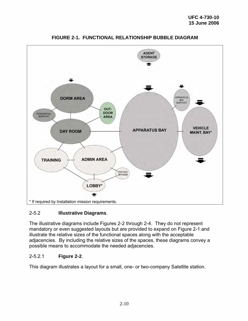
FIGURE 2-1. FUNCTIONAL RELATIONSHIP BUBBLE DIAGRAM
* If required by Installation mission requirements. 2-5.2 Illustrative Diagrams.
The illustrative diagrams include Figures 2-2 through 2-4. They do not represent mandatory or even suggested layouts but are provided to expand on Figure 2-1 and illustrate the relative sizes of the functional spaces along with the acceptable adjacencies. By including the relative sizes of the spaces, these diagrams convey a possible means to accommodate the needed adjacencies.
2-5.2.1 Figure 2-2.
This diagram illustrates a layout for a small, one- or two-company Satellite station.

UFC 4-730-10 15 June 2006
2-11
FIGURE 2-2. ILLUSTRATIVE LAYOUT DIAGRAM A – SMALL SATELLITE

UFC 4-730-10 15 June 2006
2-12
2-5.2.2 Figure 2-3.
This diagram illustrates a layout for an HQ/Main station with larger administrative and training components.
FIGURE 2-3. ILLUSTRATIVE LAYOUT DIAGRAM B – HQ/MAIN STATION
UFC 4-730-10 15 June 2006
2-13
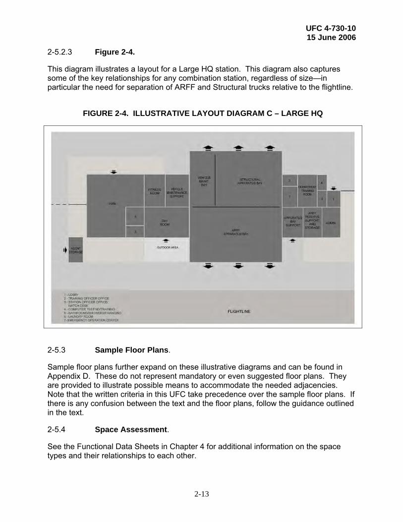
2-5.2.3 Figure 2-4.
This diagram illustrates a layout for a Large HQ station. This diagram also captures some of the key relationships for any combination station, regardless of size—in particular the need for separation of ARFF and Structural trucks relative to the flightline.
FIGURE 2-4. ILLUSTRATIVE LAYOUT DIAGRAM C – LARGE HQ
2-5.3 Sample Floor Plans.
Sample floor plans further expand on these illustrative diagrams and can be found in Appendix D. These do not represent mandatory or even suggested floor plans. They are provided to illustrate possible means to accommodate the needed adjacencies. Note that the written criteria in this UFC take precedence over the sample floor plans. If there is any confusion between the text and the floor plans, follow the guidance outlined in the text.
2-5.4 Space Assessment.
See the Functional Data Sheets in Chapter 4 for additional information on the space types and their relationships to each other.

UFC 4-730-10 15 June 2006
2-14
2-6 ALTERATIONS TO EXISTING FACILITIES.
2-6.1 Regulatory Authorities.
Refer to the following for the appropriate authorities for each Service:
• Army. AR 215. The standard may be modified to accommodate the existing structure. However, all proposed modifications to the standard must be sent to the Army Corps of Engineers, Engineering & Support Center, HSV (CEHNC) for review and HQDA (CFSC‑CYS) for approval prior to the initiation of concept design.
• Navy. Authorities are contained in OPNAVINST 11010.20F, Facilities Projects Manuals and NAVFACINST 11010.45, Comprehensive Regional Planning Instruction. Prior to planning alterations to an existing facility to convert it to a Fire Station, the activity should consult the following: CNI, HQ NAVFAC Engineering and CNI Fire & Emergency Services.
• Air Force. Consult with HQ AFCEE for architectural and publication coordination; HQ Air Force Civil Engineering Support Agency (AFCESA) for technical issues relating to fire, life safety, certification, and functional requirements; and HQ USAF/ILE for functional policies.
• Marine Corps. Consult with Headquarters Marine Corps LFF and LFL.
2-6.2 Other Considerations.
It is unlikely that a non-Fire Station facility would ever be converted to a Fire Station. However, should this need arise, consider the site and structure of the existing facility and its limitations with regard to the required functions of a Fire Station.
Consideration must be given to the adaptability of the existing facility to the intent of the Fire Station program. For instance, can the building accommodate the Apparatus Room? Does it have adequate site space for the vehicle turning radii? Whether planning a conversion, alteration, addition, or new construction, all the criteria in this UFC must be met by the resulting facility.

UFC 4-730-10 15 June 2006
3-1
CHAPTER 3 GENERAL DESIGN CRITERIA
3-1 GENERAL.
Use UFC 1-200-01, General Building Requirements for guidance on the use of model building codes for design and construction of DoD facilities. See paragraph 3-6 for the appropriate governing codes for building services.
3-2 STRUCTURE.
Refer to UFC 3-310-01, Structural Load Data. Single-story structures are preferred for Fire Stations. Site constraints may drive the need for multi-story structures. If a multi-story structure is required, ensure the appropriate adjacencies are maintained so that the required response times may be achieved. Where possible, design the structural system to accommodate future expansion requirements without over-designing the initial construction.
Refer to appendix B of UFC 4-010-01, DoD Minimum Antiterrorism Standards for Buildings, for additional minimum structural requirements of walls, glazing and doors.
3-2.1 Foundation.
The foundation is site specific and must be designed upon known geotechnical considerations by an engineer knowledgeable of the local conditions.
3-2.2 Superstructure.
Clear spans are preferred for the Apparatus Room. Use pre-engineered components for superstructure framing, where feasible.
3-2.3 Materials.
Climate conditions, high humidity, industrial atmosphere, salt water exposure, or other adverse conditions should be considered when selecting the following:
• The type of cement and admixtures used in concrete,
• The concrete cover on reinforcing steel in concrete membrane,
• The coatings on structural members,
• Expansion joints,
• The level of corrosion protection, and
• The structural systems.
3-3 EXTERIOR DESIGN.
UFC 4-730-10 15 June 2006
3-2
The building design should comply with Command and Installation architectural standards. Also consider the local geographical and cultural environment. The Fire Station should present a cohesive architectural image. Create an attractive, functional theme that applies to the entire facility design, from the overall exterior architectural statement to the specific interior design elements. Continuity of space should be reinforced by space planning, building form, elevation, materials, and details.
3-3.1 Entrance.
Ensure that the main Fire Station entrance is clearly identifiable to discourage visitors from entering the facility through an open Apparatus Bay door. In cold climates, provide a canopy (or a recess) at required egress doors to ensure that doors can completely open without obstruction from snow and ice.
Provide separate entrances to the Dorm area and the Day Room.
3-3.2 Exterior Finishes.
Exterior finishes should be durable and low-maintenance. Coordinate the exterior finishes with the Service-specific design standards noted below in paragraph 3-4.
3-4 INTERIOR DESIGN.
Construction and finishes (walls, floor, and ceiling) should support the cohesive image and theme of the facility as noted in paragraph 3-3. The living areas of the facility, such as the Day Room and the Dorm Rooms, should reflect a residential, non-institutional character.
Durability is extremely important when specifying materials for interior construction and finishes. Fire Stations are occupied 24 hours per day, seven days a week and heavy equipment is regularly handled throughout the facility. These conditions will lead to greater interior damage being incurred compared to many other facility types.
3-4.1 Interior Construction.
Counters, casework, and cabinets should be of high-quality and durable construction. Specify Architectural Woodwork Institute (AWI) Premium or Custom for finishes per AWI Quality Standards Illustrated, Current Edition. Casework, cabinet doors, and drawer faces should be provided as veneer panel core. Doors, drawers, and casework faces should be plastic laminate at a minimum. Where no water source is present, countertops should be plastic laminate as a minimum with hardwood or solid surface edging. Where a water source is present, countertops should be solid surface/solid composite plastics only. Specify 20-mm (.75-in.) minimum thickness for plywood, plywood backing, and solid wood panels.
All interior glass must be tempered safety glass and mirrors must be constructed with break-resistant materials.
3-4.2 Finishes.

UFC 4-730-10 15 June 2006
3-3
Finishes should take into account the intended uses and be highly durable. They must meet the requirements listed in NFPA 101, Life Safety Code. Also coordinate the interior (and exterior) design with the following Service-specific standards or agencies:
• Army. DG 1110-3-122, Interior Design Guide and Installation Design Guide Standards;
• Navy and Marine Corps. UFC 3-100-10N, General Architectural and Interior Design Requirements; and
• Air Force. USAF Interior Design Guide and applicable Major Command and Installation design standards.
3-4.2.1 In moist climates, do not cover the inside of exterior walls with impervious materials such as mirrors or vinyl wall coverings. This is due to a concern over mold development in the wall.
3-4.2.2 For more information on finishes in specific areas, see the Functional Data Sheets in Chapter 4.
3-5 ACOUSTICS.
The Functional Data Sheets in Chapter 4 provide minimum sound transmission coefficient (STC) ratings for the appropriate spaces. Typical STC ratings range from 35 to 55 STC depending on the space and its intended use. During design, special consideration should be given by the design team to achieving the minimum required STC values by treating wall surfaces, wall openings, and the structure with sound attenuating materials.
Per DoD Instruction 4165.57, Air Installations Compatible Use Zones (AICUZ), when a Fire Station is located near the flightline, comply with the AICUZ noise reductions for the facility location. If an AICUZ map is not available for the location, an acoustical engineer must conduct an acoustical analysis to determine the exact type and extent of the additional acoustical treatments needed to address aircraft noise.
3-6 SERVICES.
Also see paragraph 3-10 for information on sustainable design and energy consumption.
3-6.1 Plumbing.
Design domestic hot and cold water, sanitary and storm drainage, propane, fuel oil, or natural gas systems to meet the requirements of local Installation standards, and UFC 3-420-01, Plumbing Systems.
3-6.2 Heating, Ventilating, and Air Conditioning (HVAC).

UFC 4-730-10 15 June 2006
3-4
Design the HVAC system to meet the requirements of the most current edition of the International Mechanical Code (IMC); UFC 3-410-01FA, Heating, Ventilating, and Air Conditioning; and UFC 3-410-02A, Heating, Ventilating, and Air Conditioning (HVAC) Control Systems. Comply with AT requirements in the design of the HVAC system (See paragraph 3-9).
To ensure durability, consider climate conditions, high humidity, industrial atmosphere, salt water exposure, or other adverse conditions when selecting exterior HVAC components.
3-6.3 Fire Protection.
Design fire protection and life safety to comply with UFC 3-600-01, Fire Protection Engineering for Facilities and the National Fire Protection Association (NFPA) Standards, latest editions. Fire Stations must be completely protected with automatic sprinklers.
3-6.4 Electrical.
Provide electric service and distribution equipment, wiring receptacles and grounding, interior and exterior lighting and control, emergency lighting, telephone, communication systems, fire alarm, and intrusion systems in accordance with NFPA 70, National Electric Code; UFC 3-520-01, Interior Electrical Systems; and the latest installation design requirements. See the latest edition of Electric Current Abroad, U.S. Department of Commerce, to determine voltages and cycles in overseas locations. Service grounding system and all wiring methods must meet the current NFPA 70 requirements. All service equipment must be Underwriters Laboratories (UL) listed. Alternately, published proof from an approved independent testing laboratory may be provided.
3-6.4.1 Lighting.
Provide lighting and control systems throughout the facility in accordance with UFC 3-530-01, Lighting Design and Controls. Additional lighting criteria for specific spaces within a Fire Station are provided in Chapter 4.
3-6.4.2 Emergency Power.
Provide 100% emergency generator back-up power for HQ/Main and Large HQ stations. For Satellite stations, provide emergency back-up power, at a minimum, for the following spaces/systems:
• Apparatus Bay lighting and doors,
• Watch Desk/Dispatch and all associated equipment,
• IT Room systems related to the Dispatch and communication functions, and

UFC 4-730-10 15 June 2006
3-5
• Lighting.
If required by Installation mission requirements, consider providing emergency power for additional spaces, such as the Day Room, or providing 100% emergency back-up power for the entire Satellite station.
Refer to the Functional Data Sheets in Chapter 4 for the uninterrupted power supply (UPS) requirements for applicable spaces.
3-6.4.3 Communications and Data.
Telephone and data outlets may be independent of each other or combined into a single junction box. If these connections can be combined into a single junction box then the cover plate to that junction box must allow for multiple connections. In some unique situations, the cable television (CATV)/internal video connection can also be combined into a single junction box with the appropriate cover plate.
Confirm the preference for individual or combined telephone/data/video outlets with the following Service-specific contacts:
• The Installation Manager for Army and Air Force projects and
• HQ Program Managers for Navy and Marine Corps projects.
For Air Force projects, also refer to Engineering Technical Letter (ETL) 02-12, Communications and Information System Criteria for Air Force Facilities.
3-6.4.4 Alarm System.
Consider providing an intrusion detection alarm system to protect equipment and assets. Provisions for an alarm system must be justified during the planning/programming process. The Navy and Marine Corps do not fund alarm systems. If desired, the individual Navy or Marine Corps Installation must provide the funding for an alarm system.
Coordinate any closed-circuit television (CCTV)/camera systems with the appropriate Installation security office.
3-6.4.5 Firefighter Alert System.
Provide simultaneous light and audible control for the following spaces when the firefighter alert system is activated: Dorm Room lights (the dedicated alert light), corridor lights from Dorm Rooms to the Apparatus Bay, and the Apparatus Bay lights.
3-7 SITE WORK.
Organize the site to be compatible with the site planning and style of adjacent existing structures. Locate the building to reflect local climatic conditions. For example, provide protection from prevailing winds and glare and orient operable windows to take

UFC 4-730-10 15 June 2006
3-6
advantage of summer breezes. Locate the building to take advantage of passive solar heating and day lighting.
3-7.1 Landscaping.
The plant selection should be easy to maintain and enhance the visual quality of the facility in all seasons. Indigenous species are preferred. The growth characteristics of selected plant material should be assessed when considering line of sight requirements to either flight pavements or facilities. Comply with UFC 3-210-05FA, Landscape Design and Planting Criteria and the local Installation landscape standards. For Air Force, also refer to the USAF Landscape Guide and applicable Major Command and Installation standards.
Because of the proximity to the flightline for ARFF facilities, select trees and shrubs that produce little or no debris. Avoid using plants that produce fruits or nuts that may attract unwanted animals and birds to the airfield environs.
Consider sustainable design issues when designing the landscape. Select plants that require little to no additional water beyond normal rainfall. Avoid plants that require an irrigation system or consider a gray water or storm water irrigation system.
3-7.2 Firefighting Vehicle Access Drives.
Ensure that dimensions of access roadways and service entrances accommodate vehicle sizes anticipated for fire station operations. Apparatus ramps should also be designed to support the anticipated vehicle weight.
Design the facility and site to permit drive-through Apparatus Bays unless restricted by the site and/or flightline.
If the vehicle access drives are sloped, either for drainage or due to the site profile, ensure that the slope angle is low enough to be easily navigated by the firefighting apparatus and that the driver can maintain good visibility of the area around his or her vehicle.
3-7.3 Parking and Other Access Drives.
Provide adequate parking based on the total positions assigned, including eight- and 24-hour shift positions, reservists (if appropriate), and visitors. If possible, access drives to staff and public parking should not cross the vehicle access drive out of the Apparatus Bay. Locate parking areas so they do not dominate the main entrance and public image of the facility. Comply with UFC 3-210-02, POV Site Circulation and Parking and UFC 4-010-01.
3-7.4 General Site Lighting.
Ensure that parking areas and the facility have adequate lighting for safety, evacuation, and security measures. If the facility is near a flightline, site lighting should not interfere

UFC 4-730-10 15 June 2006
3-7
or be a distraction to aircraft movement at night. Comply with UFC 3-530-01, Interior and Exterior Lighting and Controls.
3-8 BARRIER-FREE DESIGN REQUIREMENTS.
Design Fire Stations to comply with the Architectural Barriers Act (Public Law 90-480) of 1968, http://www.access-board.gov/ufas/ufas-html/ufas.htm - ABA. Provide barrier-free design requirements in accordance with the Uniform Federal Accessibility Standards (UFAS), published as Federal Standard (FED-STD)-795, http://www.accessboard.gov/ ufas/ufas-html/ufas.htm, and 28 CFR Part 36, the Americans with Disabilities Act Accessibility Guidelines for Buildings and Facilities (ADAAG), http://www.accessboard. gov/adaag/html/adaag.htm.
Use the criteria that provide the greatest accessibility. Spaces in the Fire Stations that are open to the public or may be manned or maintained by handicapped personnel must be barrier-free. Spaces such as dorm rooms and staff bathrooms/shower/changing rooms, which are used solely by able-bodied staff, need not be accessible.
The ADA and ABA Accessibility Guidelines for Buildings and Facilities, http://www.access-board.gov/ada-aba.htm, was published in July 2004. These updated guidelines will supersede the Uniform Federal Accessibility Standards (UFAS), published as Federal Standard 795 and Americans With Disabilities Act Accessibility Guidelines (ADAAG) when adopted by the Department of Defense. Until then these updated guidelines are not enforceable and UFAS and ADAAG still apply. When the new guidelines are adopted, they will be referenced in this section and the criteria outlined in this section modified as necessary.
3-9 ANTITERRORISM.
Design the facility to comply with UFC 4-010-01, DoD Minimum Antiterrorism Standards for Buildings and UFC 4-021-01, Mass Notification Systems.
3-10 SUSTAINABLE DESIGN.
Use an integrated approach to the planning and design of Fire Stations that minimizes energy consumption and optimizes life cycle cost renewable energy possibilities. Use a practical combination of site selection and siting, energy conserving building envelope technologies, energy efficient lighting, occupant sensing controls, variable frequency drives for motors and exhaust fans, and high efficiency HVAC systems to achieve this goal. Incorporate renewable energy principles such as day-lighting, passive and active solar heating, natural ventilation, and photo-voltaics where they are life-cycle-cost effective.
Follow the guidance in UFC 3-400-01, Energy Conservation.
A new UFC addressing sustainable design is in draft form. When it is released, it will be referenced in this section and the criteria outlined in this section modified as necessary.
UFC 4-730-10 15 June 2006
3-8
3-10.1 Service Specific.
See the following Service-specific requirements:
3-10.1.1 Army.
Design Fire Station projects with consideration for sustainable ratings in eight facility categories: Sustainable Sites, Water Efficiency, Energy and Atmosphere, Materials and Resources, Indoor Environmental Quality, Facility Delivery Process, Current Mission, and Future Missions. The minimum rating for the Army’s Sustainability Project Rating Tool (SPiRiT) must be in accordance with the current rating. Most projects can reach the sustainability rating without increasing costs, while improving Installation sustainability and balancing available resources with customer requirements. Understanding and applying the principles of Sustainable Design and Development and using the SPiRiT rating process improves day-to-day decisions and project quality.
3-10.1.2 Navy and Marine Corps.
Use the United States Green Building Council (USGBC) LEED™ Green Building Rating System to measure the sustainability of the completed project. It can also be used during planning and design as a source of green building strategies. LEED™ addresses sustainable sites, water efficiency, energy and atmosphere, materials and resources, and indoor environmental quality. The minimum LEED™ rating of “Certified” should be met within budgetary constraints. Actual certification is encouraged for all projects, but the requirements for certification will be predetermined on a project-by-project basis.
3-10.1.3 Air Force.
It is Air Force policy to apply sustainable development concepts in the planning, design, construction, environmental management, operation, maintenance, and disposal of facilities and infrastructure projects, consistent with budget and mission requirements. Refer to HQ USAF/ILE Memo, Sustainable Development Policy and the Air Force Sustainable Facilities Guide.
3-10.2 Other Sustainable Design Criteria.
The following general references provide more information:
3-10.2.1 When specifying products that are included in EPA’s list of affirmative procurement guideline items, designers must include the requirement for these products to meet or exceed the recycled material content standards established by EPA. The list of products and their corresponding recycled content requirements are found at www.epa.gov/cpg/products.
3-10.2.2 The “Whole Building Design Guide” www.wbdg.org further explains the environmental issues related to building materials and provides technical guidance on green building material selection.

UFC 4-730-10 15 June 2006
3-9
3-10.3 DoD Energy Budget.
Design of new facilities must ensure that building energy consumption complies with UFC 3-400-01, Energy Conservation.

UFC 4-730-10 15 June 2006
4-1
CHAPTER 4 SPECIFIC DESIGN CRITERIA
4-1 INTRODUCTION.
This chapter identifies the specific design needs for each functional area as outlined in the space program. Tables 4-1 through 4-29 provide this data in a standard Functional Data Sheet format.
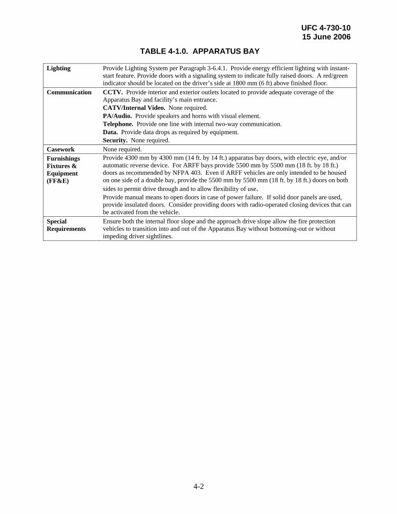
TABLE 4-1.0. APPARATUS BAY
Description/ Usage
The Apparatus Bays house the fire protection vehicles. Drive-through bays are preferable. All bays must accommodate the latest and largest structural and ARFF vehicles. Each bay of the Apparatus Room must include the required support utilities (drops) for vehicles such as exhaust, compressed air, hot and cold water, lighting, and power.
Min. Ceiling Ht. 4.26 m (14 ft.) minimum. Finishes Walls. Concrete masonry units (CMU). Provide epoxy paints on all wall surfaces. Floor. Provide a sealed concrete surface. A non-skid, low-maintenance traffic coating may
also be acceptable. Slope floor to trench drains. Ceiling. Ceiling not required; however, consider finishing exposed structure. Consider
coordinating mechanical, electrical and plumbing components. Note that none of the ceiling components can be located below minimum ceiling height.
Plumbing Provide minimum 75-mm- (3-in.-) diameter water service with 62-mm- (2.5-in.-) diameter National Standard Threads ball-valve outlet to each vehicle. Provide an emergency eye wash fountain and shower. Provide foot-operated mop sink with mop hanging rack. Provide standard hot and cold water hose bibb for every two truck bays. Provide floor trench drains parallel to the centerline of each vehicle. All apparatus room drains should connect to an approved oil/water separator prior to discharge.
HVAC The Apparatus Bay is typically heated. Maintain 20 C (68 F) minimum temperature except in areas with very mild winter conditions. Determine exceptions on a case-by-case basis based on climatic conditions. The Services will not air condition the Apparatus Bay except through exceptions. For the Army, refer to TI-800-1, Design Criteria for the appropriate exceptions. The Air Force will determine on a case-by-case basis based on climatic conditions how to condition the Apparatus Bay. In addition to considering climatic conditions, consider the energy costs and sustainability impacts. Provide a Fire Apparatus Vehicle Exhaust Removal System (FAVERS) in compliance with NFPA 1500 to eliminate 100% of vehicle exhaust emissions. A direct vent system that evacuates vehicle exhaust directly to the outside is the preferred FAVERS. Make-up air should be distributed so as to minimize drafts and be introduced above apparatus level since diesel exhaust is heavier than air. In this way, the make-up air flow downward will assist in pushing the exhaust fumes out the Apparatus bay doors when open. Provide compressed air system on self-retracting lines at each vehicle bay. Consider providing a floor radiant heating element at each bay door in colder climates to prevent the door from freezing to the pavement.
Fire Protection Provide Fire Protection System per Paragraph 3-6.3. Power Provide outlets per code. Locate all outlets at 900 mm (36 in) above finished floor. Provide self-
retracting electric drop cords between vehicles that can reach to either end of the bay. Provide backup power sized to provide full unobstructed operation capability of the apparatus bays. Provide power to each retractable bay door.
UFC 4-730-10 15 June 2006
4-2
TABLE 4-1.0. APPARATUS BAY
Lighting Provide Lighting System per Paragraph 3-6.4.1. Provide energy efficient lighting with instant-start feature. Provide doors with a signaling system to indicate fully raised doors. A red/green indicator should be located on the driver’s side at 1800 mm (6 ft) above finished floor.
Communication CCTV. Provide interior and exterior outlets located to provide adequate coverage of the Apparatus Bay and facility’s main entrance. CATV/Internal Video. None required. PA/Audio. Provide speakers and horns with visual element. Telephone. Provide one line with internal two-way communication. Data. Provide data drops as required by equipment. Security. None required.
Casework None required. Furnishings Fixtures & Equipment (FF&E)
Provide 4300 mm by 4300 mm (14 ft. by 14 ft.) apparatus bay doors, with electric eye, and/or automatic reverse device. For ARFF bays provide 5500 mm by 5500 mm (18 ft. by 18 ft.) doors as recommended by NFPA 403. Even if ARFF vehicles are only intended to be housed on one side of a double bay, provide the 5500 mm by 5500 mm (18 ft. by 18 ft.) doors on both sides to permit drive through and to allow flexibility of use. Provide manual means to open doors in case of power failure. If solid door panels are used, provide insulated doors. Consider providing doors with radio-operated closing devices that can be activated from the vehicle.
Special Requirements
Ensure both the internal floor slope and the approach drive slope allow the fire protection vehicles to transition into and out of the Apparatus Bay without bottoming-out or without impeding driver sightlines.
UFC 4-730-10 15 June 2006
4-3
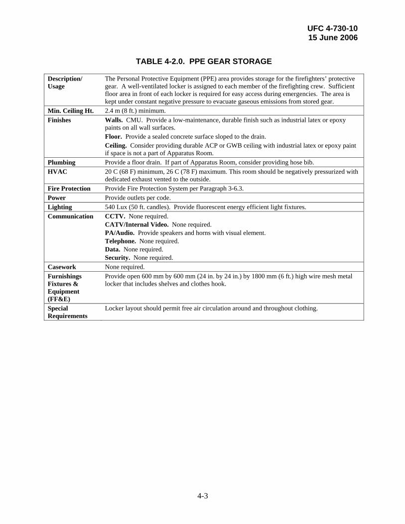
TABLE 4-2.0. PPE GEAR STORAGE
Description/ Usage
The Personal Protective Equipment (PPE) area provides storage for the firefighters’ protective gear. A well-ventilated locker is assigned to each member of the firefighting crew. Sufficient floor area in front of each locker is required for easy access during emergencies. The area is kept under constant negative pressure to evacuate gaseous emissions from stored gear.
Min. Ceiling Ht. 2.4 m (8 ft.) minimum. Finishes Walls. CMU. Provide a low-maintenance, durable finish such as industrial latex or epoxy
paints on all wall surfaces. Floor. Provide a sealed concrete surface sloped to the drain. Ceiling. Consider providing durable ACP or GWB ceiling with industrial latex or epoxy paint
if space is not a part of Apparatus Room. Plumbing Provide a floor drain. If part of Apparatus Room, consider providing hose bib. HVAC 20 C (68 F) minimum, 26 C (78 F) maximum. This room should be negatively pressurized with
dedicated exhaust vented to the outside. Fire Protection Provide Fire Protection System per Paragraph 3-6.3. Power Provide outlets per code. Lighting 540 Lux (50 ft. candles). Provide fluorescent energy efficient light fixtures. Communication CCTV. None required.
CATV/Internal Video. None required. PA/Audio. Provide speakers and horns with visual element. Telephone. None required. Data. None required. Security. None required.
Casework None required. Furnishings Fixtures & Equipment (FF&E)
Provide open 600 mm by 600 mm (24 in. by 24 in.) by 1800 mm (6 ft.) high wire mesh metal locker that includes shelves and clothes hook.
Special Requirements
Locker layout should permit free air circulation around and throughout clothing.

UFC 4-730-10 15 June 2006
4-4
TABLE 4-3.0. HOSE STORAGE
Description/ Usage
This area provides for storage of hoses. Hoses are rolled and stored on fixed or mobile storage racks.
Min. Ceiling Ht. 2.4 m (8 ft.) minimum. Finishes Walls. CMU. Provide a low-maintenance, durable finish such as industrial latex or epoxy
paints on all wall surfaces. Floor. Provide a sealed concrete surface sloped to floor drain. Ceiling. None required. Plumbing Provide a floor drain. Consider providing a hose bibb. HVAC 20 C (68 F) minimum, 26 C (78 F) maximum. Well ventilated. Fire Protection Provide Fire Protection System per Paragraph 3-6.3. Power Provide outlets per code and dedicated outlets required to support drying equipment (if
provided). Lighting 540 Lux (50 ft. candles). Provide fluorescent energy efficient light fixtures. Communication CCTV. None required.
CATV/Internal Video. None required. PA/Audio. Provide a speaker. Telephone. None required. Data. None required. Security. None required.
Casework None required. Furnishings Fixtures & Equipment (FF&E)
Provide movable racks for roll-up hose storage. Consider providing hose drying oven in areas where required by climatic conditions.
Special Requirements
UFC 4-730-10 15 June 2006
4-5
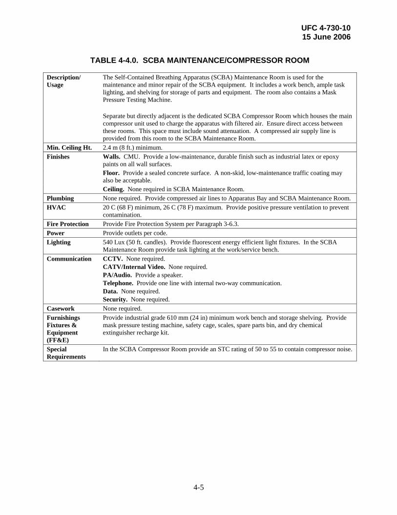
TABLE 4-4.0. SCBA MAINTENANCE/COMPRESSOR ROOM
Description/ Usage
The Self-Contained Breathing Apparatus (SCBA) Maintenance Room is used for the maintenance and minor repair of the SCBA equipment. It includes a work bench, ample task lighting, and shelving for storage of parts and equipment. The room also contains a Mask Pressure Testing Machine. Separate but directly adjacent is the dedicated SCBA Compressor Room which houses the main compressor unit used to charge the apparatus with filtered air. Ensure direct access between these rooms. This space must include sound attenuation. A compressed air supply line is provided from this room to the SCBA Maintenance Room.
Min. Ceiling Ht. 2.4 m (8 ft.) minimum. Finishes Walls. CMU. Provide a low-maintenance, durable finish such as industrial latex or epoxy
paints on all wall surfaces. Floor. Provide a sealed concrete surface. A non-skid, low-maintenance traffic coating may
also be acceptable. Ceiling. None required in SCBA Maintenance Room. Plumbing None required. Provide compressed air lines to Apparatus Bay and SCBA Maintenance Room. HVAC 20 C (68 F) minimum, 26 C (78 F) maximum. Provide positive pressure ventilation to prevent
contamination. Fire Protection Provide Fire Protection System per Paragraph 3-6.3. Power Provide outlets per code. Lighting 540 Lux (50 ft. candles). Provide fluorescent energy efficient light fixtures. In the SCBA
Maintenance Room provide task lighting at the work/service bench. Communication CCTV. None required.
CATV/Internal Video. None required. PA/Audio. Provide a speaker. Telephone. Provide one line with internal two-way communication. Data. None required. Security. None required.
Casework None required. Furnishings Fixtures & Equipment (FF&E)
Provide industrial grade 610 mm (24 in) minimum work bench and storage shelving. Provide mask pressure testing machine, safety cage, scales, spare parts bin, and dry chemical extinguisher recharge kit.
Special Requirements
In the SCBA Compressor Room provide an STC rating of 50 to 55 to contain compressor noise.
UFC 4-730-10 15 June 2006
4-6
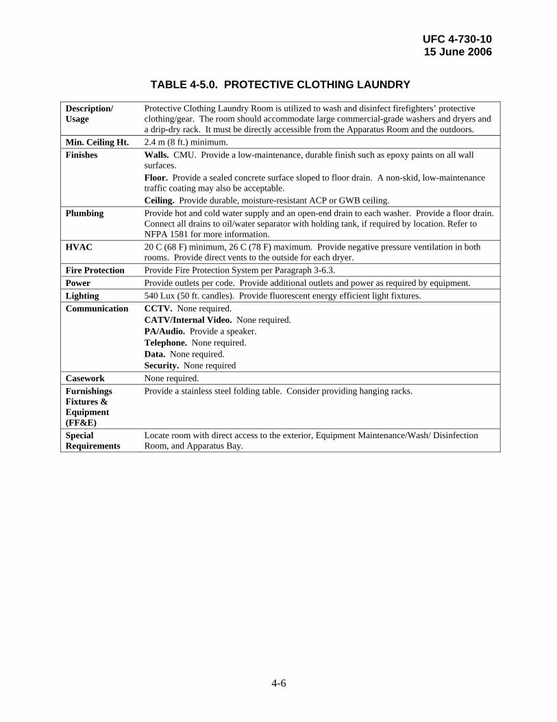
TABLE 4-5.0. PROTECTIVE CLOTHING LAUNDRY
Description/ Usage
Protective Clothing Laundry Room is utilized to wash and disinfect firefighters’ protective clothing/gear. The room should accommodate large commercial-grade washers and dryers and a drip-dry rack. It must be directly accessible from the Apparatus Room and the outdoors.
Min. Ceiling Ht. 2.4 m (8 ft.) minimum. Finishes Walls. CMU. Provide a low-maintenance, durable finish such as epoxy paints on all wall
surfaces. Floor. Provide a sealed concrete surface sloped to floor drain. A non-skid, low-maintenance
traffic coating may also be acceptable. Ceiling. Provide durable, moisture-resistant ACP or GWB ceiling. Plumbing Provide hot and cold water supply and an open-end drain to each washer. Provide a floor drain.
Connect all drains to oil/water separator with holding tank, if required by location. Refer to NFPA 1581 for more information.
HVAC 20 C (68 F) minimum, 26 C (78 F) maximum. Provide negative pressure ventilation in both rooms. Provide direct vents to the outside for each dryer.
Fire Protection Provide Fire Protection System per Paragraph 3-6.3. Power Provide outlets per code. Provide additional outlets and power as required by equipment. Lighting 540 Lux (50 ft. candles). Provide fluorescent energy efficient light fixtures. Communication CCTV. None required.
CATV/Internal Video. None required. PA/Audio. Provide a speaker. Telephone. None required. Data. None required. Security. None required
Casework None required. Furnishings Fixtures & Equipment (FF&E)
Provide a stainless steel folding table. Consider providing hanging racks.
Special Requirements
Locate room with direct access to the exterior, Equipment Maintenance/Wash/ Disinfection Room, and Apparatus Bay.
UFC 4-730-10 15 June 2006
4-7
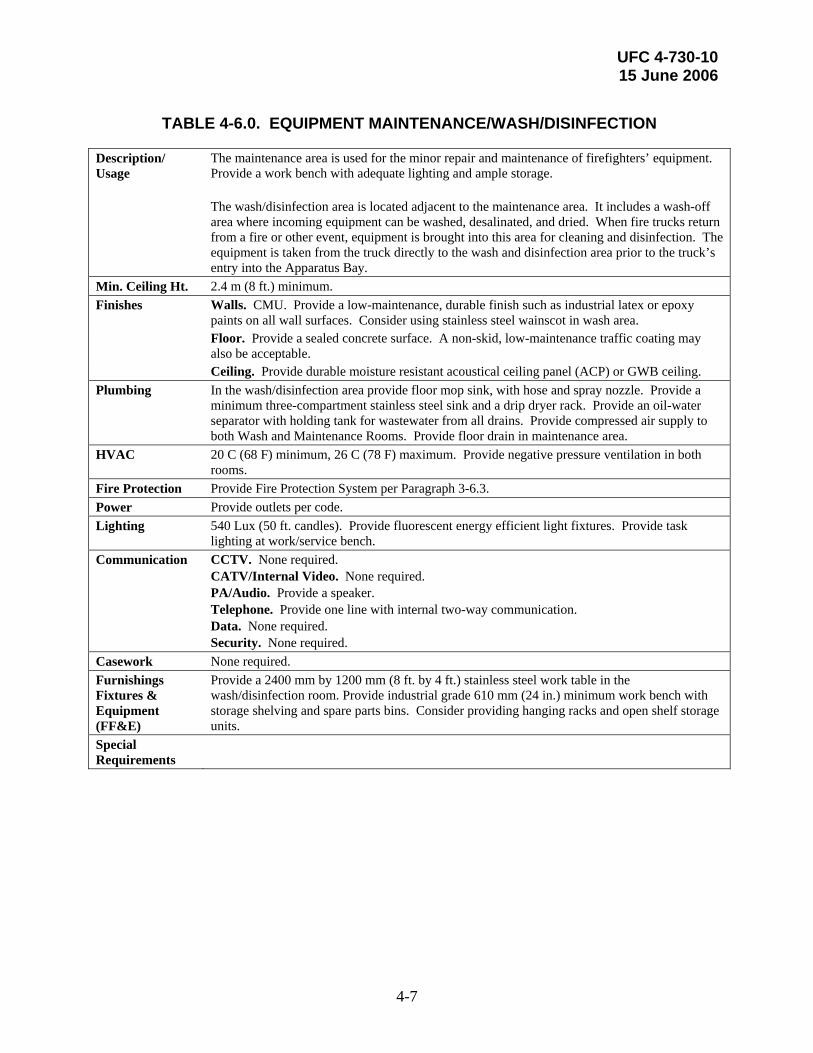
TABLE 4-6.0. EQUIPMENT MAINTENANCE/WASH/DISINFECTION
Description/ Usage
The maintenance area is used for the minor repair and maintenance of firefighters’ equipment. Provide a work bench with adequate lighting and ample storage. The wash/disinfection area is located adjacent to the maintenance area. It includes a wash-off area where incoming equipment can be washed, desalinated, and dried. When fire trucks return from a fire or other event, equipment is brought into this area for cleaning and disinfection. The equipment is taken from the truck directly to the wash and disinfection area prior to the truck’s entry into the Apparatus Bay.
Min. Ceiling Ht. 2.4 m (8 ft.) minimum. Finishes Walls. CMU. Provide a low-maintenance, durable finish such as industrial latex or epoxy
paints on all wall surfaces. Consider using stainless steel wainscot in wash area. Floor. Provide a sealed concrete surface. A non-skid, low-maintenance traffic coating may
also be acceptable. Ceiling. Provide durable moisture resistant acoustical ceiling panel (ACP) or GWB ceiling. Plumbing In the wash/disinfection area provide floor mop sink, with hose and spray nozzle. Provide a
minimum three-compartment stainless steel sink and a drip dryer rack. Provide an oil-water separator with holding tank for wastewater from all drains. Provide compressed air supply to both Wash and Maintenance Rooms. Provide floor drain in maintenance area.
HVAC 20 C (68 F) minimum, 26 C (78 F) maximum. Provide negative pressure ventilation in both rooms.
Fire Protection Provide Fire Protection System per Paragraph 3-6.3. Power Provide outlets per code. Lighting 540 Lux (50 ft. candles). Provide fluorescent energy efficient light fixtures. Provide task
lighting at work/service bench. Communication CCTV. None required.
CATV/Internal Video. None required. PA/Audio. Provide a speaker. Telephone. Provide one line with internal two-way communication. Data. None required. Security. None required.
Casework None required. Furnishings Fixtures & Equipment (FF&E)
Provide a 2400 mm by 1200 mm (8 ft. by 4 ft.) stainless steel work table in the wash/disinfection room. Provide industrial grade 610 mm (24 in.) minimum work bench with storage shelving and spare parts bins. Consider providing hanging racks and open shelf storage units.
Special Requirements

UFC 4-730-10 15 June 2006
4-8
TABLE 4-7.0. EMT STORAGE AND MEDICAL STORAGE CABINET
Description/ Usage
The EMT Storage area is for storage of basic first aid supplies. It must be directly adjacent to the Apparatus Bay. The space must be fully conditioned. The Medical Storage Cabinet is often a cabinet or subspace within the EMT Storage area and is for storage of drugs, needles, and other restricted medical supplies. Access to EMT Storage is restricted and controlled to prevent theft and abuse of controlled substances.
Min. Ceiling Ht. 2.4 m (8 ft.) minimum. Finishes Walls. Provide CMU or GWB wall with a low-maintenance, durable finish such as industrial
latex paint. Floor. Provide low-maintenance sheet or tile vinyl flooring material with rubber base. Ceiling. Provide ACP ceiling. Plumbing None required. HVAC 20 C (68 F) minimum, 26 C (78 F) maximum. Fire Protection Provide Fire Protection System per Paragraph 3-6.3. Power Provide outlets per code. Lighting 540 Lux (50 ft. candles). Provide fluorescent energy efficient light fixtures. Communication CCTV. None required.
CATV/Internal Video. None required. PA/Audio. None required. Telephone. None required. Data. None required. Security. None required.
Casework None required. Furnishings Fixtures & Equipment (FF&E)
Provide wall or free standing shelving units. Provide a lockable cabinet for the EMT Storage to store drugs and other restricted supplies.
Special Requirements
Consider providing a keyed lock set at the access point to the space.

UFC 4-730-10 15 June 2006
4-9
TABLE 4-8.0. HAZMAT/CBRNE EQUIPMENT STORAGE
Description/ Usage
HAZMAT/CBRNE Equipment Storage is a separate storage facility housing only equipment classified for use with hazardous materials. Provide sufficient floor and open shelf storage areas.
Min. Ceiling Ht. 2.4 m (8 ft.) minimum. Finishes Walls. CMU. Provide a low-maintenance, durable finish such as industrial latex paint. Floor. Provide a sealed concrete surface. A non-skid, low-maintenance traffic coating may
also be acceptable. Ceiling. None required. Plumbing None required. HVAC 20 C (68 F) minimum, 26 C (78 F) maximum. This room should be negatively pressurized with
dedicated exhaust vented to the outside. Fire Protection Provide Fire Protection System per Paragraph 3-6.3. Power Provide outlets per code. Lighting 215 Lux (20 ft. candles). Provide fluorescent energy efficient light fixtures. Communication CCTV. None required.
CATV/Internal Video. None required. PA/Audio. Provide a speaker. Telephone. None required. Data. None required. Security. None required.
Casework None required. Furnishings Fixtures & Equip. (FF&E)
Provide industrial storage shelving units and racks.
Special Requirements

UFC 4-730-10 15 June 2006
4-10
TABLE 4-9.0. AGENT STORAGE
Description/ Usage
Agent Storage is typically a single-story structure separate from the fire station building. It should be located along the drive leading into the Apparatus Bay for ease of loading and unloading of firefighting agents. In some cases, it may be attached to the main structure.
Min. Ceiling Ht. 2.4 m (8 ft.) minimum. Finishes Walls. None required. Unless structure is wood or metal stud construction, provide plywood
sheathing for protection. Floor. Provide a sealed concrete surface. Ceiling. None required. Plumbing None required. HVAC Provide heating where required by location to prevent agents from freezing. Fire Protection Provide Fire Protection System per Paragraph 3-6.3. Power Provide outlets per code. Lighting 215 Lux (20 ft. candles). Provide fluorescent energy efficient light fixtures. Communication CCTV. None required.
CATV/Internal Video. None required. PA/Audio. None required. Telephone. None required. Data. None required. Security. None required.
Casework Furnishings Fixtures & Equipment (FF&E)
Special Requirements
Provide double or overhead-type exterior doors. Consider providing insulated doors in locations where required by climatic conditions.
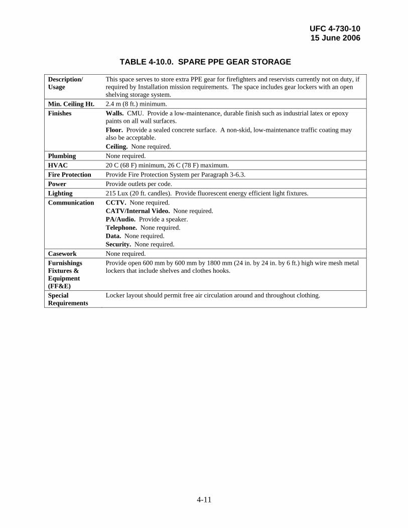
UFC 4-730-10 15 June 2006
4-11
TABLE 4-10.0. SPARE PPE GEAR STORAGE
Description/ Usage
This space serves to store extra PPE gear for firefighters and reservists currently not on duty, if required by Installation mission requirements. The space includes gear lockers with an open shelving storage system.
Min. Ceiling Ht. 2.4 m (8 ft.) minimum. Finishes Walls. CMU. Provide a low-maintenance, durable finish such as industrial latex or epoxy
paints on all wall surfaces. Floor. Provide a sealed concrete surface. A non-skid, low-maintenance traffic coating may
also be acceptable. Ceiling. None required. Plumbing None required. HVAC 20 C (68 F) minimum, 26 C (78 F) maximum. Fire Protection Provide Fire Protection System per Paragraph 3-6.3. Power Provide outlets per code. Lighting 215 Lux (20 ft. candles). Provide fluorescent energy efficient light fixtures. Communication CCTV. None required.
CATV/Internal Video. None required. PA/Audio. Provide a speaker. Telephone. None required. Data. None required. Security. None required.
Casework None required. Furnishings Fixtures & Equipment (FF&E)
Provide open 600 mm by 600 mm by 1800 mm (24 in. by 24 in. by 6 ft.) high wire mesh metal lockers that include shelves and clothes hooks.
Special Requirements
Locker layout should permit free air circulation around and throughout clothing.

UFC 4-730-10 15 June 2006
4-12
TABLE 4-11.1. FIRE EXTINGUISHER (NON FLIGHTLINE)
MAINTENANCE AND STORAGE
Description/ Usage
The non-flightline Fire Extinguisher Maintenance and Storage includes an indoor storage/maintenance room and possibly an outdoor storage area. The indoor storage/maintenance room accommodates a work bench with adequate lighting to perform maintenance and service of extinguishers, safety cage, scale, recharge kit, and parts storage bins. Provide open shelving for storage of extinguishers. The outdoor storage area is covered and enclosed with a secured screen. This may be combined with the Flightline Fire Extinguisher Maintenance and Storage Area and made as one space with no dividing walls.
Min. Ceiling Ht. 2.4 m (8 ft.) minimum. Finishes Walls. CMU. Provide a low-maintenance, durable finish such as industrial latex or epoxy
paints on all wall surfaces. Floor. Provide a sealed concrete surface. Ceiling. None required. Plumbing Provide a hose bibb and floor drain. Provide eye wash fountain in Maintenance Room. HVAC 20 C (68 F) minimum, 26 C (78 F) maximum. Provide negative pressure ventilation with an
exhaust hood. Provide fume discharge to the exterior. Provide a compressed air system with self-retracting lines at the work bench.
Fire Protection Provide Fire Protection System per Paragraph 3-6.3. Power Provide outlets per code. Lighting 540 Lux (50 ft. candles). Provide fluorescent energy efficient light fixtures. Provide task
lighting at work/service bench. Communication CCTV. None required.
CATV/Internal Video. None required. PA/Audio. Provide a speaker. Telephone. Provide one line with internal two-way communication. Data. Provide quad outlet at work bench and in locations where required to accommodate equipment. Security. None required.
Casework None required. Furnishings Fixtures & Equipment (FF&E)
Provide double leaf doors to exterior. Provide industrial grade 610 mm (24 in) minimum work bench, storage shelving, spare parts bin, flammable storage locker, and a floor scale.
Special Requirements
Locate access to Fire Extinguisher Maintenance and Storage away from Apparatus Bay exterior circulation.
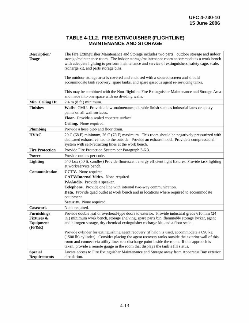
UFC 4-730-10 15 June 2006
4-13
TABLE 4-11.2. FIRE EXTINGUISHER (FLIGHTLINE)
MAINTENANCE AND STORAGE
Description/ Usage
The Fire Extinguisher Maintenance and Storage includes two parts: outdoor storage and indoor storage/maintenance room. The indoor storage/maintenance room accommodates a work bench with adequate lighting to perform maintenance and service of extinguishers, safety cage, scale, recharge kit, and parts storage bins. The outdoor storage area is covered and enclosed with a secured screen and should accommodate tank recovery, spare tanks, and spare gaseous agent re-servicing tanks. This may be combined with the Non-flightline Fire Extinguisher Maintenance and Storage Area and made into one space with no dividing walls.
Min. Ceiling Ht. 2.4 m (8 ft.) minimum. Finishes Walls. CMU. Provide a low-maintenance, durable finish such as industrial latex or epoxy
paints on all wall surfaces. Floor. Provide a sealed concrete surface. Ceiling. None required. Plumbing Provide a hose bibb and floor drain. HVAC 20 C (68 F) minimum, 26 C (78 F) maximum. This room should be negatively pressurized with
dedicated exhaust vented to the outside. Provide an exhaust hood. Provide a compressed air system with self-retracting lines at the work bench.
Fire Protection Provide Fire Protection System per Paragraph 3-6.3. Power Provide outlets per code. Lighting 540 Lux (50 ft. candles) Provide fluorescent energy efficient light fixtures. Provide task lighting
at work/service bench. Communication CCTV. None required.
CATV/Internal Video. None required. PA/Audio. Provide a speaker. Telephone. Provide one line with internal two-way communication. Data. Provide quad outlet at work bench and in locations where required to accommodate equipment. Security. None required.
Casework None required. Furnishings Fixtures & Equipment (FF&E)
Provide double leaf or overhead-type doors to exterior. Provide industrial grade 610 mm (24 in.) minimum work bench, storage shelving, spare parts bin, flammable storage locker, agent and nitrogen storage, dry chemical extinguisher recharge kit, and a floor scale. Provide cylinder for extinguishing agent recovery (if halon is used, accommodate a 690 kg (1500 lb) cylinder). Consider placing the agent recovery tanks outside the exterior wall of this room and connect via utility lines to a discharge point inside the room. If this approach is taken, provide a remote gauge in the room that displays the tank’s fill status.
Special Requirements
Locate access to Fire Extinguisher Maintenance and Storage away from Apparatus Bay exterior circulation.

UFC 4-730-10 15 June 2006
4-14
TABLE 4-12.0. VEHICLE MAINTENANCE BAY
Description/ Usage
This space is mainly used to service and repair firefighting vehicles, if required by Installation mission requirements. At times, this bay may be used as an additional Apparatus Bay as well. The bay is sized to accommodate the largest vehicle and the equipment required to service it. Similar to the Apparatus Bay, the Vehicle Maintenance Bay should be a drive-through.
Min. Ceiling Ht. 4.26 m (14 ft.) minimum. Finishes Walls. CMU. Provide epoxy paints on all wall surfaces. Floor. Provide a sealed concrete surface. A non-skid, low-maintenance traffic coating may
also be acceptable. Ceiling. Ceiling not required; however, consider finishing exposed structure. Consider
coordinating mechanical, electrical, and plumbing components. Note that none of the ceiling components can be located below minimum ceiling height.
Plumbing Provide minimum 75-mm- (3-in.-) diameter water service with 62-mm- (2.5 in) diameter National Standard Threads ball valved outlet to each vehicle. Provide standard hot and cold water hose bibb. Provide floor trench drains parallel to the centerline of each vehicle. Trench drain should connect to an approved oil/water separator prior to discharge to the sanitary sewer.
HVAC The Vehicle Maintenance Bay is typically heated. Maintain 20 C (68 F) minimum temperature except in areas with very mild winter conditions. Determine exceptions on a case-by-case basis based on climatic conditions. The Services will not air condition the Vehicle Maintenance Bay except through exceptions. : For the Army, refer to TI-800-1, Design Criteria for the appropriate exceptions. The Air Force will determine on a case-by-case basis based on climatic conditions how to condition the Apparatus Bay. In addition to considering climatic conditions, consider the energy costs and sustainability impacts. Provide a Fire Apparatus Vehicle Exhaust Removal System (FAVERS) in compliance with NFPA 1500 to eliminate 100% of vehicle exhaust emissions. A direct vent system that evacuates vehicle exhaust directly to the outside is the preferred FAVERS. Make-up air should be distributed so as to minimize drafts and be introduced above apparatus level since diesel exhaust is heavier than air. In this way, the make-up air flow downward will assist in pushing the exhaust fumes out the Apparatus bay doors when open. Provide compressed air system on self-retracting lines at each vehicle bay. Consider providing floor radiant heating element at each door in colder climates to prevent the door from freezing to the pavement.
Fire Protection Provide Fire Protection System per Paragraph 3-6.3. Power Provide outlets per code. Locate all outlets at 900 mm (36 in.) above finished floor. Provide
self-retracting electric drop cords between vehicles. Provide backup power sized to provide full unobstructed operation capability of the Apparatus Bays and Vehicle Maintenance Bay. Provide power to each retractable door.
Lighting Provide Lighting System per Paragraph 3-6.4.1. Provide energy efficient lighting with instant-start feature. Provide doors with signaling system indicating fully raised doors. A red/green indicator should be located on the driver’s side at 1800 mm (6 ft.) above finished floor.
Communication CCTV. Provide interior and exterior and cameras located to provide adequate coverage. CATV/Internal Video. None required. PA/Audio. Provide speakers and horns with visual element. Telephone. Provide one line with internal two-way communication. Data. Provide data drops as required by equipment. Security. None required.
Casework None required.

UFC 4-730-10 15 June 2006
4-15
TABLE 4-12.0. VEHICLE MAINTENANCE BAY
Furnishings Fixtures & Equip. (FF&E)
Provide tool storage bins and industrial work benches.
Special Requirements
Consider providing hydraulic lifts and/or overhead lift/crane.
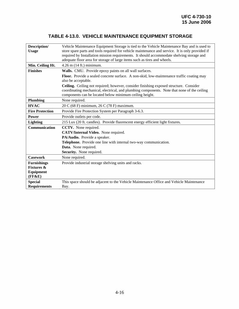
UFC 4-730-10 15 June 2006
4-16
TABLE 4-13.0. VEHICLE MAINTENANCE EQUIPMENT STORAGE
Description/ Usage
Vehicle Maintenance Equipment Storage is tied to the Vehicle Maintenance Bay and is used to store spare parts and tools required for vehicle maintenance and service. It is only provided if required by Installation mission requirements. It should accommodate shelving storage and adequate floor area for storage of large items such as tires and wheels.
Min. Ceiling Ht. 4.26 m (14 ft.) minimum. Finishes Walls. CMU. Provide epoxy paints on all wall surfaces. Floor. Provide a sealed concrete surface. A non-skid, low-maintenance traffic coating may
also be acceptable. Ceiling. Ceiling not required; however, consider finishing exposed structure. Consider
coordinating mechanical, electrical, and plumbing components. Note that none of the ceiling components can be located below minimum ceiling height.
Plumbing None required. HVAC 20 C (68 F) minimum, 26 C (78 F) maximum. Fire Protection Provide Fire Protection System per Paragraph 3-6.3. Power Provide outlets per code. Lighting 215 Lux (20 ft. candles). Provide fluorescent energy efficient light fixtures. Communication CCTV. None required.
CATV/Internal Video. None required. PA/Audio. Provide a speaker. Telephone. Provide one line with internal two-way communication. Data. None required. Security. None required.
Casework None required. Furnishings Fixtures & Equipment (FF&E)
Provide industrial storage shelving units and racks.
Special Requirements
This space should be adjacent to the Vehicle Maintenance Office and Vehicle Maintenance Bay.
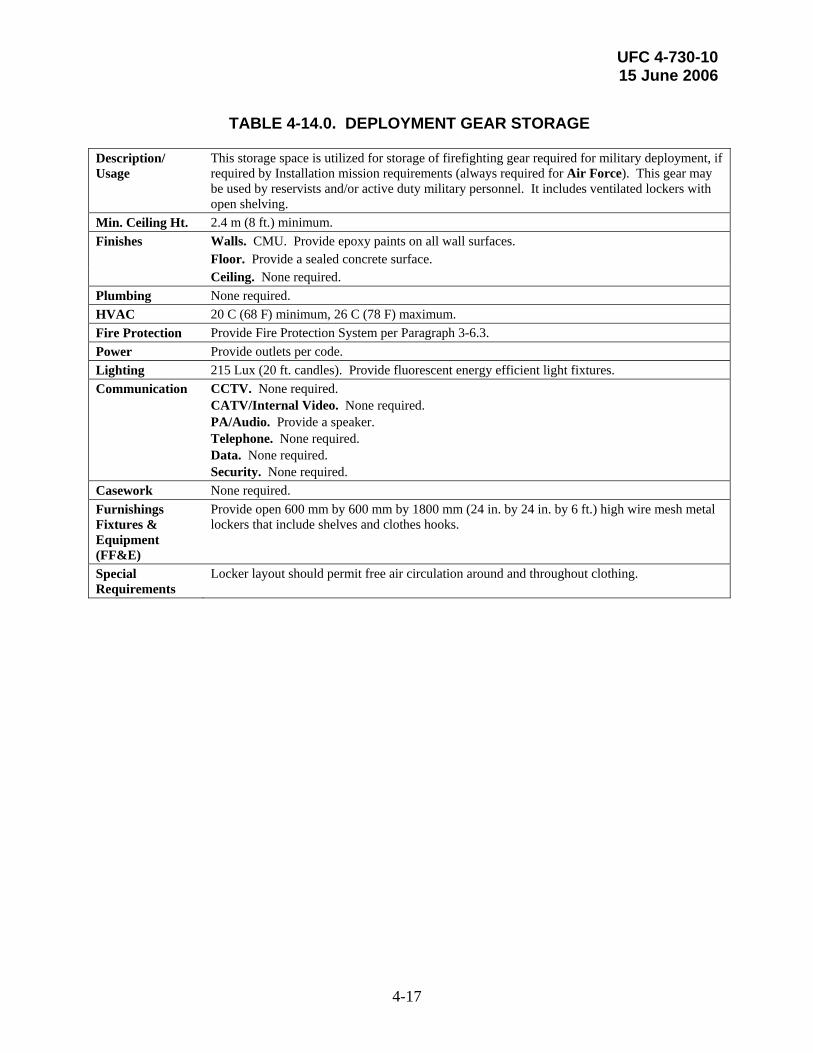
UFC 4-730-10 15 June 2006
4-17
TABLE 4-14.0. DEPLOYMENT GEAR STORAGE
Description/ Usage
This storage space is utilized for storage of firefighting gear required for military deployment, if required by Installation mission requirements (always required for Air Force). This gear may be used by reservists and/or active duty military personnel. It includes ventilated lockers with open shelving.
Min. Ceiling Ht. 2.4 m (8 ft.) minimum. Finishes Walls. CMU. Provide epoxy paints on all wall surfaces. Floor. Provide a sealed concrete surface. Ceiling. None required. Plumbing None required. HVAC 20 C (68 F) minimum, 26 C (78 F) maximum. Fire Protection Provide Fire Protection System per Paragraph 3-6.3. Power Provide outlets per code. Lighting 215 Lux (20 ft. candles). Provide fluorescent energy efficient light fixtures. Communication CCTV. None required.
CATV/Internal Video. None required. PA/Audio. Provide a speaker. Telephone. None required. Data. None required. Security. None required.
Casework None required. Furnishings Fixtures & Equipment (FF&E)
Provide open 600 mm by 600 mm by 1800 mm (24 in. by 24 in. by 6 ft.) high wire mesh metal lockers that include shelves and clothes hooks.
Special Requirements
Locker layout should permit free air circulation around and throughout clothing.

UFC 4-730-10 15 June 2006
4-18
TABLE 4-15.0. STATION OFFICER’S OFFICE/WATCH DESK
Description/ Usage
The Station Officer’s Office provides space for the station officer and/or company officers to perform their administrative functions. For Satellite stations the Station Officers office may serve to control public access to the station. If a Watch Desk function is required, it is typically included in the Station Officer’s Office. The Watch Desk receives emergency calls from the Dispatch and contains the security monitors for the station. It is usually occupied 24 hours a day/7 days a week.
Min. Ceiling Ht. 2.4 m (8 ft.) minimum. Finishes Walls. Provide a low-maintenance, durable finish such as egg-shell latex paint. Floor. Provide low maintenance sheet or tile vinyl flooring material. Consider providing
durable commercial carpeting. Ceiling. Provide ACP ceiling system. Plumbing None required. HVAC 20 C (68 F) minimum, 26 C (78 F) maximum. Fire Protection Provide Fire Protection System per Paragraph 3-6.3. Power Provide outlets per code, and as needed to support the extensive equipment required. In
addition to above-noted power requirements, provide two additional quad outlets at the control center console. Provide a switch controlling operation of Apparatus Bay doors.
Lighting 540 Lux (50 ft. candles). Provide fluorescent energy efficient light fixtures. Provide task lighting at control desk. Firefighter Alert System: Provide light and audible control for the following elements when the firefighter alert system is activated: Dorm Room lights (the dedicated alert light), corridor lights from Dorm Rooms to Apparatus Bay, and the Apparatus Bay lights.
Communication CCTV. Provide outlets required to support required equipment. CATV/Internal Video. Provide outlets required to support required equipment. PA/Audio. Provide simultaneous light and audible control for the entire fire station. Telephone. Provide regular and secure multi-telephone line required to support switch board operation, telephone, and fax. Data. Provide regular and secure data outlets to support required equipment. Security. Provide vision panel to the Apparatus Bay. Provide pin pad/cipher electric lock with remote push button release and manual key override.
Casework None required. Furnishings Fixtures & Equipment (FF&E)
Provide control center console. Provide modular component workstations to accommodate computers, monitor screens, two-way radios, and audio equipment. Provide recording system to record all emergency radio and telephone conversations. Provide wall-mounted Installation grid coordinate map. Provide map racks. Provide safes for classified technical manuals. Provide book cases and ergonomically designed seating.
Special Requirements
Provide a 920 mm (36 in) free access area around the entire control console. Provide space for Emergency Information Systems computer. Provide tinted widows with blinds. Consider providing handicapped-accessible toilet. Provide an STC rating of 50 to 55.

UFC 4-730-10 15 June 2006
4-19
TABLE 4-16.0. FIRE CHIEF’S AND DEPUTY FIRE CHIEF’S OFFICES
Description/ Usage
The Fire Chief’s and Deputy Fire Chief’s Offices are two separate offices that will not exist in every station. When they are both located in a station, they are adjacent to each other and to an administrative assistant and a Chief’s Conference Room. Each office includes a typical office space and workstation. An adjacent private bedroom and private toilet are shared by both offices and should be directly accessible by both offices. Consider making the bedroom/toilet portion part of the standard station dorm room area for added flexibility.
Min. Ceiling Ht. 2.4 m (8 ft.) minimum. Finishes Walls. Provide a low-maintenance, durable finish such as egg-shell latex paint. In toilet
consider providing moisture and mildew resistant gypsum wall board, with ceramic tile wainscot, and semi-gloss industrial latex-based paint
Floor. Provide durable commercial carpeting with rubber base in office and sleeping areas. Provide ceramic tile and ceramic tile base in toilet.
Ceiling. Provide ACP or gypsum board ceiling. Provide moisture resistant gypsum board ceiling in the toilet. Consider egg-shell latex paint in office and sleeping areas, and semi-gloss industrial paint in the toilet.
Plumbing Provide water closet, shower, and lavatory. Consider providing floor drain. HVAC 20 C (68 F) minimum, 26 C (78 F) maximum. Provide exhaust fan in private toilet. Consider
providing independent thermostat. Fire Protection Provide Fire Protection System per Paragraph 3-6.3. Provide smoke and CO detectors. Power Provide outlets per code. Lighting 540 Lux (50 ft. candles). Provide fluorescent energy efficient light fixtures. Consider
providing task lighting at individual desks. Consider providing residential-style light fixtures. In addition to the ambient and task lighting fixtures, provide a dedicated alert light fixture that is controllable from the Watch Desk/Dispatch and tied into the firefighting alert system with a red-tinted bulb or lens.
Communication CCTV. None required. CATV/Internal Video. None required. PA/Audio. Provide a speaker. Telephone. Provide one line with internal two-way communication. Data. Provide data outlets to support required equipment. Security. None required.
Casework None required. Furnishings Fixtures & Equipment (FF&E)
Provide office desk, office chair, file cabinet, bookshelf, desk lamp, and additional side chair. In the private bedroom provide twin bed, night stand, and a wardrobe. Provide window blinds.
Special Requirements
In Air Force and large Army/Navy facilities where an Assistant Fire Chief exists, he or she should share a private toilet with the Deputy Fire Chief, and the Fire Chief should be provided with his or her own private toilet. There also may be a requirement for a Chief’s Conference Room. If required, this would be directly adjacent to or expand out of the Chief’s Office. It provides space for a small conference table for 8 to 10 people.

UFC 4-730-10 15 June 2006
4-20
TABLE 4-17.0. OFFICES
Description/ Usage
General administrative office spaces in the station include the following: Assistant Chief/Shift Supervisor Office, Inspector’s Office(s), Training Officer Office, Vehicle Maintenance Office, EMS Office, Dispatch Supervisor (if provided), Administrative Assistant, Reservist Office (if provided), Assistant Chief of Fire Prevention (if provided), HAZMAT/Safety Officer (if provided), and Logistics Officer (if provided). The offices are generally grouped together in the Administrative component of the Fire Station. The Administrative Assistant is generally only provided if the Chief and Deputy Chief are resident in the station, in which case this area also doubles as the general reception area for the facility and is located directly off of the lobby (see Table 4-18).
Min. Ceiling Ht. 2.4 m (8 ft.) minimum. Finishes Walls. Provide a low-maintenance, durable finish such as egg-shell latex paint. Floor. Provide low maintenance sheet or tile vinyl flooring material with rubber base.
Consider providing durable commercial carpeting. Ceiling. Provide ACP ceiling. Plumbing None required. HVAC 20 C (68 F) minimum, 26 C (78 F) maximum. Fire Protection Provide Fire Protection System per Paragraph 3-6.3. Power Provide outlets per code. Lighting Provide Lighting System per Paragraph 3-6.4.1. Communication CCTV. None required.
CATV/Internal Video. None required. PA/Audio. Provide a speaker. Telephone. Provide one line with internal two-way communication. Data. Provide data outlets to support required equipment. Security. None required.
Casework None required. Furnishings Fixtures & Equipment (FF&E)
Provide office desk, office chair, file cabinet, bookshelf, desk lamp, and an additional side chair. For a more executive-level office, consider providing credenza and two additional side chairs.
Special Requirements
The Vehicle Maintenance Office will be located near the Vehicle Maintenance Bay and Storage. It will likely have CMU walls and more durable finishes than typical offices.

UFC 4-730-10 15 June 2006
4-21
TABLE 4-18.0. LOBBY
Description/ Usage
The lobby is generally only provided if the Department Chief and Deputy Chief are resident in the station. It serves as the entrance to the facility and gathering/waiting space for the visiting public. The lobby should be adjacent to the administrative component of the facility. It should also be recognizable from the outside and a well-lit, inviting space.
Min. Ceiling Ht. 2.4 m (8 ft.) minimum. Finishes Walls. Provide a low-maintenance, durable finish such as industrial egg-shell latex paint.
Consider providing rubber or paper wall coverings Floor. Provide low-maintenance sheet or tile vinyl flooring material with rubber base.
Consider stone or quarry tile with stone or tile base. Ceiling. Provide acoustical and decorative ACP or gypsum board ceiling such as egg-shell
latex paint for gypsum board ceiling. Plumbing None Required. Consider providing a drinking fountain. HVAC 20 C (68 F) minimum, 26 C (78 F) maximum. Fire Protection Provide Fire Protection System per Paragraph 3-6.3. Power Provide outlets per code. Consider outlets for display cases. Lighting Provide Lighting System per Paragraph 3-6.4.1. Consider decorative lighting fixtures and task
lighting. Communication CCTV. Provide at least one outlet.
CATV/Internal Video. None required. PA/Audio. Provide a speaker. Telephone. Consider providing one line for local and toll-free calls or a pay phone. Data. None required. Security. None required.
Casework Consider providing display cases. Furnishings Fixtures & Equipment (FF&E)
Provide walk-off matt at entrance (consider a built-in mat), soft padded furniture, side tables, magazine rack, and tack surfaces.
Special Requirements
Provide airlock at main entrance when necessary and signage.
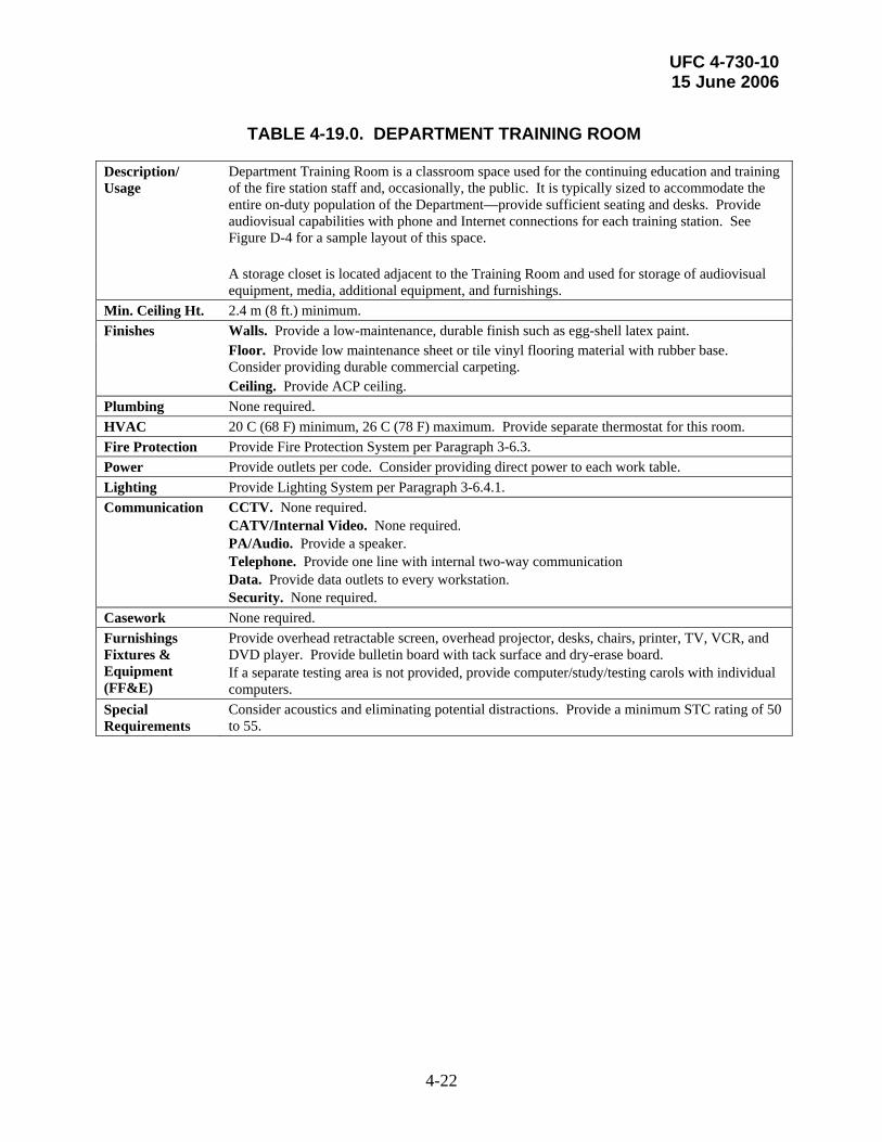
UFC 4-730-10 15 June 2006
4-22
TABLE 4-19.0. DEPARTMENT TRAINING ROOM
Description/ Usage
Department Training Room is a classroom space used for the continuing education and training of the fire station staff and, occasionally, the public. It is typically sized to accommodate the entire on-duty population of the Department—provide sufficient seating and desks. Provide audiovisual capabilities with phone and Internet connections for each training station. See Figure D-4 for a sample layout of this space. A storage closet is located adjacent to the Training Room and used for storage of audiovisual equipment, media, additional equipment, and furnishings.
Min. Ceiling Ht. 2.4 m (8 ft.) minimum. Finishes Walls. Provide a low-maintenance, durable finish such as egg-shell latex paint. Floor. Provide low maintenance sheet or tile vinyl flooring material with rubber base.
Consider providing durable commercial carpeting. Ceiling. Provide ACP ceiling. Plumbing None required. HVAC 20 C (68 F) minimum, 26 C (78 F) maximum. Provide separate thermostat for this room. Fire Protection Provide Fire Protection System per Paragraph 3-6.3. Power Provide outlets per code. Consider providing direct power to each work table. Lighting Provide Lighting System per Paragraph 3-6.4.1. Communication CCTV. None required.
CATV/Internal Video. None required. PA/Audio. Provide a speaker. Telephone. Provide one line with internal two-way communication Data. Provide data outlets to every workstation. Security. None required.
Casework None required. Furnishings Fixtures & Equipment (FF&E)
Provide overhead retractable screen, overhead projector, desks, chairs, printer, TV, VCR, and DVD player. Provide bulletin board with tack surface and dry-erase board. If a separate testing area is not provided, provide computer/study/testing carols with individual computers.
Special Requirements
Consider acoustics and eliminating potential distractions. Provide a minimum STC rating of 50 to 55.

UFC 4-730-10 15 June 2006
4-23
TABLE 4-20.0. TESTING/INDIVIDUAL STUDY AREA
Description/ Usage
This area consists of individual computer/study carols for study and testing of firefighters. Each of these stations must be private to eliminate potential for cheating during testing and to facilitate quiet study. See Figure D-5 for a sample layout of this space.
Min. Ceiling Ht. 2.4 m (8 ft.) minimum. Finishes Walls. Provide a low-maintenance, durable finish such as egg-shell latex paint. Floor. Provide low-maintenance sheet or tile vinyl flooring material with rubber base.
Consider providing durable commercial carpeting. Ceiling. Provide ACP ceiling. Plumbing None required. HVAC 20 C (68 F) minimum, 26 C (78 F) maximum. Consider providing separate thermostat for this
room. Fire Protection Provide Fire Protection System per Paragraph 3-6.3. Power Provide outlets per code. Provide direct power to each computer/study carol and for other
equipment such as printers. Lighting 540 Lux (50 ft. candles). Provide fluorescent energy efficient light fixtures. Communication CCTV. Provide video camera with monitor located in Testing Officer Office.
CATV/Internal Video. None required. PA/Audio. Provide a speaker Telephone. None required. Data. Provide data outlets to all workstations and equipment. Security. None required.
Casework None required. Furnishings Fixtures & Equipment (FF&E)
Provide four computer/study carols (to accommodate one company) and printer(s), office chairs, and task lights.
Special Requirements
Provide a minimum STC rating of 50 to 55.

UFC 4-730-10 15 June 2006
4-24
TABLE 4-21.0. DISPATCH
Description/ Usage
The Dispatch Room defines the similar functions for Fire-only Dispatch and Consolidated Dispatch Rooms. This room functions to receive and dispatch emergency related calls. Fire-only Dispatch rooms are solely responsible for receiving and dispatching fire related emergency calls. A Consolidated Dispatch Room handles fire, security, and medical response service calls. Not every station includes a Dispatch. The Dispatch Room includes workstations sized to accommodate the necessary equipment for each individual dispatcher. In larger Dispatch Rooms, a separate, adjacent room for the Dispatch Supervisor is required. The finishes and mechanical/electrical requirements for this room are the same for Offices (see Table 4-17). Dispatch Rooms also include a dedicated toilet and kitchenette directly adjacent to and accessible from to the room for staff use. Figures D-6.1 and D-6.2 illustrate sample layouts of the Dispatch Room.
Min. Ceiling Ht. 2.4 m (8 ft.) minimum. Finishes Walls. Provide a low-maintenance, durable finish such as industrial egg-shell latex paint. Floor. Provide low-maintenance sheet or tile vinyl flooring material with rubber base.
Consider providing durable commercial carpeting. Ceiling. Provide ACP ceiling. Plumbing Provide a handicapped accessible toilet with a lavatory and water closet. Provide a kitchenette
with a kitchen sink and disposal. HVAC 20 C (68 F) minimum, 26 C (78 F) maximum. Provide independent environmental control
equipment. Provide exhaust for the toilet as required by code. Fire Protection Provide Fire Protection System per Paragraph 3-6.3. Power Provide outlets per code and as needed to support all equipment, including charging
equipment for handhelds. Provide a switch controlling open only operation of Apparatus Bay doors. The generator must provide back-up power for all Dispatch Room systems. In addition, provide uninterrupted power supply (UPS) for all Dispatch Room systems. The UPS will provide an uninterrupted flow of power to gap between the time of power loss and the time that generator is providing power.
Lighting 540 Lux (50 ft. candles). Provide fluorescent energy efficient light fixtures. Consider providing task lighting at control desk. Firefighter Alert System: Provide light and audible control for the following elements when the firefighter alert system is activated: Dorm Room lights (the dedicated alert light), corridor lights from Dorm Rooms to Apparatus Bay, and the Apparatus Bay lights.
Communication CCTV. Monitors for the facility cameras will be located here. Provide outlets required to support equipment. CATV/Internal Video. Provide outlets required to support equipment. PA/Audio. Provide a speaker and a microphone. Telephone. Provide regular and secure multi-telephone line required to support switchboard operation, telephone, and fax. Data. Provide regular and secure data outlets to support required equipment. Security. Provide vision panel to the Apparatus Bay. Provide pin pad/cipher electric lock with remote push button release and manual key override.
Casework At kitchenette, provide wall and base cabinets with 610 mm (24 in.) solid surface work counter.

UFC 4-730-10 15 June 2006
4-25
TABLE 4-21.0. DISPATCH
Furnishings Fixtures & Equipment (FF&E)
Provide control center console. Provide modular component workstations to accommodate computers, monitor screens, two-way radios and audio equipment. Provide recording system to record all emergency radio and telephone conversations. Provide wall-mounted Installation grid coordinate map. Provide map racks. Provide safes for classified technical manuals. Provide book cases, and ergonomically designed seating. Provide a secure drawer or safe for storage of classified documents. Security must meet SECRET criteria.
Special Requirements
Note that some equipment requires free access area around the entire control console. Design this space appropriate to the equipment being provided. Note any special requirements for the E911 system, if appropriate. Provide space for Emergency Information Systems computer. Provide tinted widows with blinds. If possible, operators should be able to see exterior conditions. Also consider providing visible access to the flightline if appropriate. Provide an STC rating of 50 to 55.
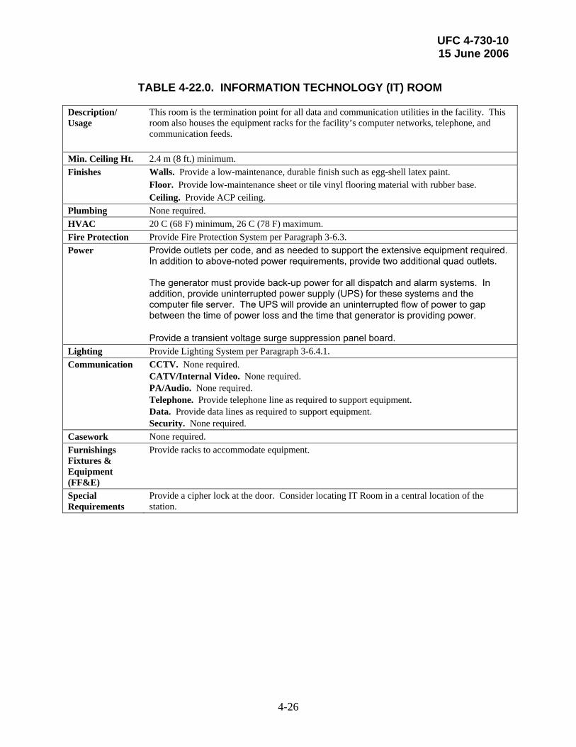
UFC 4-730-10 15 June 2006
4-26
TABLE 4-22.0. INFORMATION TECHNOLOGY (IT) ROOM
Description/ Usage
This room is the termination point for all data and communication utilities in the facility. This room also houses the equipment racks for the facility’s computer networks, telephone, and communication feeds.
Min. Ceiling Ht. 2.4 m (8 ft.) minimum. Finishes Walls. Provide a low-maintenance, durable finish such as egg-shell latex paint. Floor. Provide low-maintenance sheet or tile vinyl flooring material with rubber base. Ceiling. Provide ACP ceiling. Plumbing None required. HVAC 20 C (68 F) minimum, 26 C (78 F) maximum. Fire Protection Provide Fire Protection System per Paragraph 3-6.3. Power Provide outlets per code, and as needed to support the extensive equipment required.
In addition to above-noted power requirements, provide two additional quad outlets. The generator must provide back-up power for all dispatch and alarm systems. In addition, provide uninterrupted power supply (UPS) for these systems and the computer file server. The UPS will provide an uninterrupted flow of power to gap between the time of power loss and the time that generator is providing power. Provide a transient voltage surge suppression panel board.
Lighting Provide Lighting System per Paragraph 3-6.4.1. Communication CCTV. None required.
CATV/Internal Video. None required. PA/Audio. None required. Telephone. Provide telephone line as required to support equipment. Data. Provide data lines as required to support equipment. Security. None required.
Casework None required. Furnishings Fixtures & Equipment (FF&E)
Provide racks to accommodate equipment.
Special Requirements
Provide a cipher lock at the door. Consider locating IT Room in a central location of the station.

UFC 4-730-10 15 June 2006
4-27
TABLE 4-23.0. DAY/TRAINING ROOM (Including Kitchen)
Description/ Usage
The Day Room is configured and furnished like a very large residential kitchen/dining room/living room. It should be flexible to accommodate a number of different activities. The dining area must accommodate dining, informal meetings, and group training for the number of companies on duty. Provide plenty of controllable natural light, and adequate seating to accommodate all company members—both in the dining setting and comfortable seating for TV watching, reading, and relaxation in the living room area. Directly adjacent to the dining area is a kitchen sized to provide ample preparation space for the entire overnight population of the station. The kitchen should resemble a residential kitchen as much as possible. Provide separate dry and cold food storage for two shifts. Consider providing additional cold and dry food storage for a swing shift and/or other facility occupants. Figures D-7.1 through D-7.4 illustrate sample layouts of the Day Room and its individual components. If a host nation day room is provided, refer to the contractual agreement and points of contact for size, space, and operational criteria.
Min. Ceiling Ht. 2.4 m (8 ft.) minimum. Finishes Walls. Provide a low-maintenance, durable finish such as industrial egg-shell latex
paint in Dining and Living Room areas and semi-gloss industrial latex based paint in the kitchen area.
Floor. Provide low-maintenance sheet or tile vinyl flooring material with rubber base. In Living Room area. Consider providing commercial carpeting.
Ceiling. Provide ACP or GWB with egg-shell latex paint. Plumbing Provide hot and cold water supply in kitchen. Provide cold water connections for the coffee
and ice makers. Provide two-basin, deep kitchen sink. Provide connections to dishwashers. Provide a floor drain.
HVAC 20 C (68 F) minimum, 26 C (78 F) maximum. Provide exhaust hood over kitchen stoves appropriate to the grade of equipment provided.
Fire Protection Provide Fire Protection System per Paragraph 3-6.3. Refer to NFPA 96 to confirm fire protection requirements for the grade of kitchen equipment provided.
Power Provide outlets per code. Provide outlets to accommodate all kitchen equipment. Provide dedicated circuits as necessary to minimize power interruptions.
Lighting 540 Lux (50 ft. candles). Provide incandescent energy efficient light fixtures. Consider residential-style lighting fixtures. Consider providing dimmers for all light fixtures.
Communication CCTV. None required. CATV/Internal Video. Provide at least one outlet in the living room area. PA/Audio. Provide a speaker. Telephone. Provide one line with internal two-way communication. Data. Provide at least one outlet in the dining/training area. Consider providing outlets in the living room area. Security. None required.
Casework Provide base and wall cabinets with 610 mm (24 in) solid surface work counter.

UFC 4-730-10 15 June 2006
4-28
TABLE 4-23.0. DAY/TRAINING ROOM (Including Kitchen)
Furnishings Fixtures & Equipment (FF&E)
Kitchen area: Provide refrigerators with freezers, large-capacity dishwashers, stove/range, exhaust hood, microwave oven, commercial-grade coffee maker, toaster oven, and ice maker. For one- to two-company satellite stations, provide residential grade equipment. For HQ or larger stations, consider providing light commercial-grade equipment. Note that separate cold and dry storage must be provided for two shifts. Dining/Training area: Provide dining table with chairs, bulletin board with tack surface. Living Room area: Provide recliner armchairs, side tables, entertainment center, large-screen TV, VCR, and DVD player. Consider providing bookshelves and coffee table(s).
Special Requirements
Provide an STC rating of 50 to 55.

UFC 4-730-10 15 June 2006
4-29
TABLE 4-24.0. DORM ROOMS
Description/ Usage
Dorm Rooms are the private quarters of the firefighters and are used for sleeping during 24-hour shift. The room is shared between two firefighters of different crews/shifts so that the room is never occupied simultaneously. Individual lockers are provided for each firefighter. A bed, nightstand, and desk are shared. A two-bed arrangement, giving each firefighter an individual bed and nightstand, has become a desirable option in recent years. Wall-beds, also known as “Murphy-beds,” are also becoming a common alternative. These combine the personality of an individual bed with added space savings. The room should be a comfortable, inviting space that promotes relaxation. Acoustical privacy between rooms is important. Provide direct access to a private corridor and means of natural light in every room (consider AT issues, especially in OCONUS locations with regard to natural light provisions). See Figures D-8.1 through D-8.3 for three possible Dorm Room layouts.
Min. Ceiling Ht. 2.4 m (8 ft.) minimum. Finishes Walls. Provide a low-maintenance, durable finish such as egg-shell latex paint. Floor. Provide durable commercial carpeting with rubber base. Ceiling. Provide painted gypsum ceiling with egg-shell latex paint. Plumbing None required. HVAC 20 C (68 F) minimum, 26 C (78 F) maximum. Provide individual thermostats. Fire Protection Provide Fire Protection System per Paragraph 3-6.3. Provide smoke and CO detectors. Power Provide outlets per code. Lighting Provide Lighting System per Paragraph 3-6.4.1.
In addition to the ambient and task lighting fixtures, provide a dedicated alert light fixture that is controllable from the Watch Desk/Dispatch and tied into the firefighting alert system with a red-tinted bulb or lens.
Communication CCTV. None required. CATV/Internal Video. Provide one outlet. PA/Audio. Provide a speaker. Telephone. Provide one line with internal two-way communication. Data. Provide one outlet. Security. None required.
Casework None required. Furnishings Fixtures & Equipment (FF&E)
Provide extra-long twin bed, night table, two wardrobes, desk and desk chair, desk light, and alarm clock. As an alternative to a shared bed, provide two retractable wall beds.
Special Requirements
Provide an STC rating of 50 to 55.

UFC 4-730-10 15 June 2006
4-30
TABLE 4-25.0. BATHROOMS/SHOWERS/CHANGING
Description/ Usage
The Bathroom/Shower/Changing Room includes private water closets, lavatory, and shower stalls with private changing area for the personal use of the firefighters. Also provide lockers for temporary storage of personal items within this room. These lockers are not for storage of PPE gear. See Figure D-9 for a sample layout of the Bathrooms/Shower/Changing space.
Min. Ceiling Ht. 2.4 m (8 ft.) minimum. Finishes Walls. Provide a low-maintenance, durable finish such as industrial semi-gloss latex or epoxy
paint. Provide full-height ceramic tile. Floor. Provide slip resistant ceramic tile. Ceiling. Provide skim-coated cementicious backerboard ceiling. Plumbing Provide shower stalls, lavatories, and water closets. See Special Requirements below for
male/female distribution. HVAC 20 C (68 F) minimum, 26 C (78 F) maximum. Provide exhaust fans in toilet and shower areas. Fire Protection Provide Fire Protection System per Paragraph 3-6.3. Power Provide outlets per code. Lighting Provide Lighting System per Paragraph 3-6.4.1. Communication CCTV. None required.
CATV/Internal Video. None required. PA/Audio. Provide a speaker. Telephone. None required. Data. None required. Security. None required.
Casework Provide 610 mm (24 in) minimum solid surface materials for countertops and shower and toilet partitions.
Furnishings Fixtures & Equipment (FF&E)
Special Requirements
Divide facilities as follows for smaller stations: • One-Company Station: Provide 1 water closet, 1 shower, and 1 lavatory for females, and
provide 2 water closets, 2 showers, and 2 lavatories for males. • Two-Company Station: Provide 1 water closet, 1 shower, and 1 lavatory for females, and
provide 4 water closets, 4 showers, and 3 lavatories for males. For larger stations, consult with user and local codes for final fixture count, but consider both the heavy, concentrated usage of the toilets after a call and the disparity between male and female fixture counts. Fire Stations offer an excellent opportunity to achieve sustainable design rating points for providing shower facilities for 15% of the building’s population.

UFC 4-730-10 15 June 2006
4-31
TABLE 4-26.0. FITNESS ROOM
Description/ Usage
The Fitness Room promotes health and physical fitness of fire department personnel. The Fitness Room should accommodate the latest in fitness machines, as well as more traditional equipment. The room should be sized to provide free circulation between equipment while in use. If the Physical Therapy/Sauna is required by the Installation mission, locate it adjacent to the Fitness Room and/or Bathroom/Shower/ Changing Room. See Figure D-10 for a sample layout of the Fitness Room.
Min. Ceiling Ht. 2.4 m (8 ft.) minimum. Finishes Walls. Provide a low-maintenance, durable finish such as industrial egg-shell latex
paint. Floor. Provide low-maintenance sheet or tile vinyl flooring material with rubber base.
Consider cork floor. Ceiling. Provide acoustical ACP or gypsum board ceiling with a finish such as industrial egg-
shell latex paint for gypsum board ceiling. Plumbing None required. If sauna is provided, consider providing cold water faucet and a floor drain. HVAC 20 C (68 F) minimum, 26 C (78 F) maximum. Provide additional supply and exhaust.
Consider providing ceiling fans. Fire Protection Provide Fire Protection System per Paragraph 3-6.3. Power Provide wall outlets per code. Provide wall or floor outlets to accommodate fitness machines
such as treadmills, bikes, and stair-step machines. Provide power supply with a dedicated circuit required to accommodate sauna’s heating element.
Lighting Provide Lighting System per Paragraph 3-6.4.1. Communication CCTV. None required.
CATV/Internal Video. Provide at least one outlet for a wall-mounted unit. PA/Audio. Provide a speaker. Telephone. Provide one line with internal two-way communication. Data. None required. Security. None required.
Casework None required. Furnishings Fixtures & Equipment (FF&E)
Provide fitness machines, treadmill, stationary bicycle, elliptical machine, weights, and mats. Consider providing for a wall-mounted television.
Special Requirements
Provide full-wall-height mirrors on at least one wall. Provide an STC rating of 50 to 55.
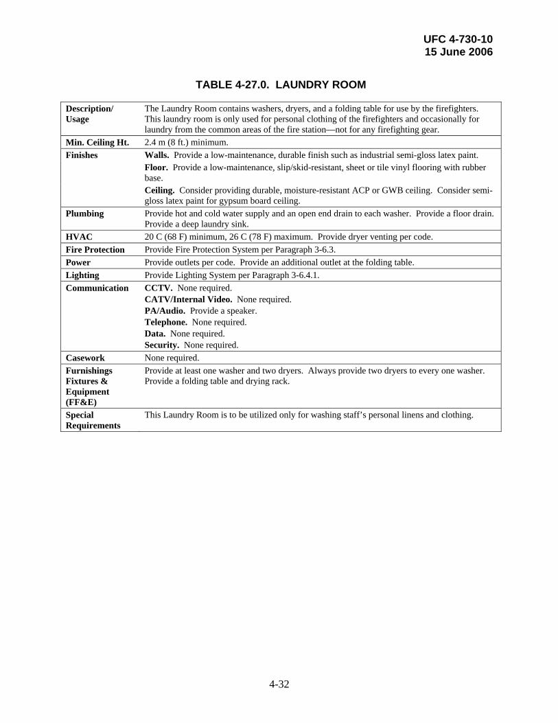
UFC 4-730-10 15 June 2006
4-32
TABLE 4-27.0. LAUNDRY ROOM
Description/ Usage
The Laundry Room contains washers, dryers, and a folding table for use by the firefighters. This laundry room is only used for personal clothing of the firefighters and occasionally for laundry from the common areas of the fire station—not for any firefighting gear.
Min. Ceiling Ht. 2.4 m (8 ft.) minimum. Finishes Walls. Provide a low-maintenance, durable finish such as industrial semi-gloss latex paint. Floor. Provide a low-maintenance, slip/skid-resistant, sheet or tile vinyl flooring with rubber
base. Ceiling. Consider providing durable, moisture-resistant ACP or GWB ceiling. Consider semi-
gloss latex paint for gypsum board ceiling. Plumbing Provide hot and cold water supply and an open end drain to each washer. Provide a floor drain.
Provide a deep laundry sink. HVAC 20 C (68 F) minimum, 26 C (78 F) maximum. Provide dryer venting per code. Fire Protection Provide Fire Protection System per Paragraph 3-6.3. Power Provide outlets per code. Provide an additional outlet at the folding table. Lighting Provide Lighting System per Paragraph 3-6.4.1. Communication CCTV. None required.
CATV/Internal Video. None required. PA/Audio. Provide a speaker. Telephone. None required. Data. None required. Security. None required.
Casework None required. Furnishings Fixtures & Equipment (FF&E)
Provide at least one washer and two dryers. Always provide two dryers to every one washer. Provide a folding table and drying rack.
Special Requirements
This Laundry Room is to be utilized only for washing staff’s personal linens and clothing.

UFC 4-730-10 15 June 2006
4-33
TABLE 4-28.0. RECREATION ROOM
Description/ Usage
If required by the Installation mission, this room provides space for the firefighters to engage in noisier recreational activities, such as table games (e.g., pool or table tennis) or video games and is in addition to the Day Room. Provide some acoustical separation from the Day Room and the Dorm Rooms.
Min. Ceiling Ht. 2.4 m (8 ft.) minimum. Finishes Walls. Provide a low-maintenance, durable finish such as industrial egg-shell latex paint. Floor. Provide low-maintenance sheet or tile vinyl flooring material with rubber base.
Consider providing durable commercial carpeting. Ceiling. Provide acoustical ACP or gypsum board ceiling such as industrial egg-shell latex
paint for gypsum board ceiling. Plumbing None required. HVAC 20 C (68 F) minimum, 26 C (78 F) maximum. Consider providing a separate thermostat for
this space. Fire Protection Provide Fire Protection System per Paragraph 3-6.3. Power Provide outlets per code. Provide power required to accommodate any game equipment. Lighting 540 Lux (50 ft. candles). Provide incandescent energy efficient light fixtures. Consider
residential-style lighting fixtures. Consider providing dimmer for all light fixtures. Communication CCTV. None required.
CATV/Internal Video. Provide at least one outlet. Consider height of outlet for a wall-mounted television. PA/Audio. Provide a speaker. Telephone. Provide one line with internal two-way communication. Data. None required. Security. None required.
Casework None required. Furnishings Fixtures & Equipment (FF&E)
Provide pool table/table-tennis table, lounge chairs, side tables, bar stools, book cases, and storage cabinets.
Special Requirements
Provide an STC rating of 50 to 55.

UFC 4-730-10 15 June 2006
4-34
TABLE 4-29.0. VENDING
Description/ Usage
The vending area accommodates two or more vending machines for snacks and drinks. The vending area should be conveniently located for the use of firefighters and fire station staff. Do not place vending machines in the Day Room or Lobby. Recommended locations include the Recreation Room (if provided) or an alcove off of a main hallway.
Min. Ceiling Ht. 2.4 m (8 ft.) minimum. Finishes Walls. Provide a low-maintenance, durable finish such as egg-shell latex paint. Floor. Provide low-maintenance sheet or tile vinyl flooring material with rubber base. Ceiling. Provide ACP or painted gypsum ceiling. Plumbing None required. HVAC 20 C (68 F) minimum, 26 C (78 F) maximum. Fire Protection Provide Fire Protection System per Paragraph 3-6.3. Power Provide outlets per code. Provide outlets and power required by vending machines. Lighting 215 Lux (20 ft. candles). Provide fluorescent energy efficient light fixtures. Communication CCTV. None required.
CATV/Internal Video. None required. PA/Audio. None required. Telephone. None required. Data. None required. Security. None required.
Casework None required. Furnishings Fixtures & Equipment (FF&E)
Special Requirements
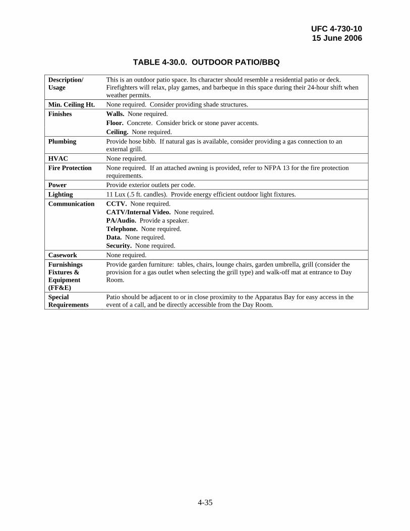
UFC 4-730-10 15 June 2006
4-35
TABLE 4-30.0. OUTDOOR PATIO/BBQ
Description/ Usage
This is an outdoor patio space. Its character should resemble a residential patio or deck. Firefighters will relax, play games, and barbeque in this space during their 24-hour shift when weather permits.
Min. Ceiling Ht. None required. Consider providing shade structures. Finishes Walls. None required. Floor. Concrete. Consider brick or stone paver accents. Ceiling. None required. Plumbing Provide hose bibb. If natural gas is available, consider providing a gas connection to an
external grill. HVAC None required. Fire Protection None required. If an attached awning is provided, refer to NFPA 13 for the fire protection
requirements. Power Provide exterior outlets per code. Lighting 11 Lux (.5 ft. candles). Provide energy efficient outdoor light fixtures. Communication CCTV. None required.
CATV/Internal Video. None required. PA/Audio. Provide a speaker. Telephone. None required. Data. None required. Security. None required.
Casework None required. Furnishings Fixtures & Equipment (FF&E)
Provide garden furniture: tables, chairs, lounge chairs, garden umbrella, grill (consider the provision for a gas outlet when selecting the grill type) and walk-off mat at entrance to Day Room.
Special Requirements
Patio should be adjacent to or in close proximity to the Apparatus Bay for easy access in the event of a call, and be directly accessible from the Day Room.

UFC 4-730-10 15 June 2006
4-36
TABLE 4-31.0. EOC SITUATION ROOM
Description/ Usage
This Emergency Operations Center Situation Room is a specialized conference room used in cases of major operations to manage and coordinate rescue and emergency service efforts, if required by the Installation mission. It should be set-up to handle planned and ad-hoc meetings and a high volume of telephone and computer communications.
Min. Ceiling Ht. 2.4 m (8 ft.) minimum. Finishes Walls. Provide a low-maintenance, durable finish such as egg-shell latex paint. Floor. Provide low-maintenance sheet or tile vinyl flooring material with rubber base.
Consider providing durable commercial carpeting. Ceiling. Provide ACP ceiling. Plumbing None required. HVAC 20 C (68 F) minimum, 26 C (78 F) maximum. Fire Protection Provide Fire Protection System per Paragraph 3-6.3. Power Provide outlets per code and as needed to support all equipment. Lighting Provide Lighting System per Paragraph 3-6.4.1. Communication CCTV. Provide outlets required to support equipment.
CATV/Internal Video. Provide outlets required to support equipment. PA/Audio. Provide a speaker and a microphone. Telephone. Provide regular and secure multi-telephone line required to support telephone and fax. Data. Provide regular and secure data outlets to support required equipment. Security. None required.
Casework Consider providing built-in case work such as a counter and base cabinets. Furnishings Fixtures & Equipment (FF&E)
Provide conference table, conference room chairs, side tables, retractable projector screen, and overhead projector, other audio/visual equipment, televisions (consider flat screen for wide angle viewing), wall-mounted grid map and map racks, and tack and dry-erase boards.
Special Requirements
Locate EOC Situation Room in an interior area of the building, adjacent to the Dispatch. Classified information may be accessed in this room. If so, address security, visibility, and data handling issues. Provide an STC rating of 50 or better.

UFC 4-730-10 15 June 2006
A-1
APPENDIX A REFERENCES
GOVERNMENT PUBLICATIONS: 1. Department of Defense (DOD) http://65.204.17.188//report/doc-ufc.html UFC 1-200-01, General Building
Requirements UFC 3-210-02, POV Site Circulation and
Parking UFC 3-210-05FA, Landscape Design
and Planting Criteria UFC 3-310-01, Structural Load Data UFC 3-400-01, Energy Conservation UFC 3-410-01FA, Heating, Ventilating,
and Air Conditioning UFC 3-410-02A, Heating, Ventilating,
and Air Conditioning (HVAC) Control Systems
UFC 3-420-01, Plumbing Systems UFC 3-520-01, Interior Electrical
Systems UFC 3-530-01, Interior and Exterior
Lighting and Controls UFC 3-600-01, Fire Protection
Engineering for Facilities UFC 4-010-01, DoD Minimum
Antiterrorism Standards for Buildings UFC 4-021-01, Mass Notification
Systems Instruction 4165.57, Air Installations
Compatible Use Zones
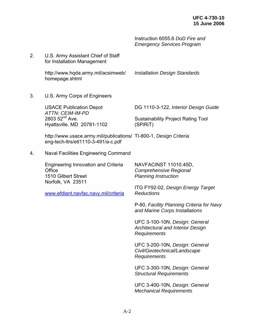
UFC 4-730-10 15 June 2006
A-2
Instruction 6055.6 DoD Fire and
Emergency Services Program 2. U.S. Army Assistant Chief of Staff for Installation Management http://www.hqda.army.mil/acsimweb/ Installation Design Standards homepage.shtml 3. U.S. Army Corps of Engineers USACE Publication Depot DG 1110-3-122, Interior Design Guide ATTN: CEIM-IM-PD 2803 52nd Ave. Sustainability Project Rating Tool Hyattsville, MD 20781-1102 (SPiRiT) http://www.usace.army.mil/publications/ TI-800-1, Design Criteria eng-tech-ltrs/etl1110-3-491/a-c.pdf 4. Naval Facilities Engineering Command Engineering Innovation and Criteria NAVFACINST 11010.45D, Office Comprehensive Regional 1510 Gilbert Street Planning Instruction Norfolk, VA 23511 ITG FY92-02, Design Energy Target www.efdlant.navfac.navy.mil/criteria Reductions P-80, Facility Planning Criteria for Navy and Marine Corps Installations UFC 3-100-10N, Design: General
Architectural and Interior Design Requirements
UFC 3-200-10N, Design: General
Civil/Geotechnical/Landscape Requirements
UFC 3-300-10N, Design: General
Structural Requirements UFC 3-400-10N, Design: General
Mechanical Requirements
UFC 4-730-10 15 June 2006
A-3
UFC 3-500-10N, Design: General Electrical Requirements
UFC 3-600-10N, Design: General Fire
Protection Requirements UFC 3-800-10N, Design: General
Environmental Requirements 5. SECNAV/OPNAV Directives Control Office N09B15 OPNAVINST 11010.20F, Facilities
Projects Manual Washington Navy Yard, Bldg. 36 720 Kennon Street, SE Rm 203 Washington Navy Yard, DC 20374 http://neds.nebt.daps.mil/usndirs.htm 6. U.S. Air Force Center for Environmental Excellence HQ AFCEE Air Force Interior Design Guide 3300 Sidney Brooks Brooks City-Base TX 78235-5112 USAF Landscape Guide www.afcee.brooks.af.mil/ Air Force Sustainable Facilities Guide HQ USAF/ILE Memo, Sustainable
Development Policy 7. U.S. Air Force Civil Engineer Support Agency HQ AFCESA/CEXF USAF Fire Station Design Guide – 1997 139 Barnes Drive, Suite 1 Tyndall AFB, FL 32403-5319 www.afcesa.af.mil

UFC 4-730-10 15 June 2006
A-4
8. Headquarters U.S. Marine Corps 2 Navy Annex MCO P11000.11B, Marine Corps Fire Washington, DC 20380-1775 Protection and Emergency Services
Program and P-80 Facility Planning 9. U.S. Department of Homeland Security, U.S. Fire Administration FA-168, Safety and Health 16825 S. Seton Avenue Considerations for the Design of Emmitsburg, MD 21727 Fire and Emergency Medical (301) 447-1000 Services Stations www.usfa.fema.gov/index.shtm 10. U.S. Department of Commerce International Trade Administration Electric Current Abroad (1998) 14th & Constitution Ave, NW Washington, DC 20230 (202) 482-3917 www.ita.doc.gov 11. U.S. Environmental Protection Agency Office of Solid Waste (5305W) Comprehensive Procurement 1200 Pennsylvania Avenue, NW Guidelines Washington, DC 20460 (800) 424-9346 www.epa.gov/cpg/products 12. National Institute of Building Sciences 1090 Vermont Avenue, NW Whole Building Design Guide Suite 700 www.wbdg.org Washington, DC 20005-4905 (202) 289-7800 www.nibs.org

UFC 4-730-10 15 June 2006
A-5
13. National Archives and Records Administration 700 Pennsylvania Avenue, NW Architectural Barriers Act (Public Washington, DC 20408 Law 90-480) of 1968 (866) 325-7208 http://www.access-board.gov/ufas/ufas-html/ufas.htm - ABA. http://www.access-board.gov/ufas/ Uniform Federal Accessibility ufas-html/ufas.htm Standards (UFAS), published as
Federal Standard (FED-STD)-795, http://www.access-board.gov/adaag/ 28 CFR Part 36, the Americans html/adaag.htm with Disabilities Act Accessibility
Guidelines for Buildings and Facilities (ADAAG),

UFC 4-730-10 15 June 2006
A-6
NON-GOVERNMENT PUBLICATIONS: 1. Architectural Woodwork Institute 1952 Isaac Newton Square West AWI Quality Standards Reston, VA 20190 Illustrated, Current Edition (703) 733-0600 www.awinet.org 2. International Code Council Headquarters International Plumbing Code 5203 Leesburg Pike Suite 600 International Mechanical Code Falls Church, VA 22041 International Building Code www.iccsafe.org 3. National Fire Protection Association 1 Batterymarch Park NFPA 13 Standard for the Installation of Quincy, Massachusetts 02169-7471 Sprinkler Systems (617) 770-3000 NFPA 70 National Electric Code www.nfpa.org (2002) NFPA 96 Standard for Ventilation
Control and Fire Protection of Commercial Cooking Operations
NFPA 101 Life Safety Code NFPA 403 Standard for Aircraft Rescue
and Fire Fighting Services at Airports NFPA 1500 Fire Department
Occupational Safety and Health Program
NFPA 1581 Fire Department Infection
Control Program

UFC 4-730-10 15 June 2006
A-7
4. The United States Green Building Council US Green Building Council LEED™ Green Building Rating 1015 18th Street, NW, Suite 805 System Washington, DC 20036 www.usgbc.org

UFC 4-730-10 15 June 2006
B-1
APPENDIX B GLOSSARY
ACRONYMS AND ABBREVIATIONS.
ACP: Acoustical Ceiling Panel
ADAAG: Americans with Disabilities Act Accessibility Guidelines for Buildings and Facilities
ARFF: Aircraft Rescue Firefighting
AT: Antiterrorism
AWI: American Woodworking Institute
CATV: Cable Television
CBRNE: Chemical, Biological, Radiological, Nuclear, Explosive
CCTV: Closed-circuit Television
CMU: Concrete Masonry Units
CO: Carbon Monoxide
CONUS: Continental United States
DoD: Department of Defense
EMS: Emergency Medical Services
EMT: Emergency Medical Technician
EOC: Emergency Operations Center
ETL: Engineering Technical Letter
FAVERS: Fire Apparatus Vehicle Exhaust Removal System
FED STD: Federal Standard
GWB: Gypsum Wall Board
HAZMAT: Hazardous Materials
HQ: Headquarters
HVAC: Heating, Ventilating, and Air Conditioning
IMC: International Mechanical Code

UFC 4-730-10 15 June 2006
B-2
IPC: International Plumbing Code
IT: Information Technology
LEED™: Leadership in Energy and Environmental Design™
MAJCOM: Major Command
MCO: Marine Corps Order
MLC: Master Labor Contracts
NFPA: National Fire Protection Association
OCONUS: Outside Continental United States
PA: Public Address
PPE: Personal Protective Equipment
SCBA: Self-contained Breathing Apparatus
SOFA: Status of Forces Agreement
SPIRIT: Sustainability Project Rating Tool
STC: Sound Transmission Coefficient
UFAS: Uniform Federal Accessibility Standards
UFC: Unified Facilities Criteria
UL: Underwriters’ Laboratories
USGBC: United States Green Building Council

UFC 4-730-10 15 June 2006
C-1
APPENDIX C SPACE PROGRAM
C-1 SAMPLE INTERACTIVE WORKSHEETS.
Figures C-1.1 through C-1.4 illustrate a sample Interactive Worksheet completed for a hypothetical Air Force Large Headquarters Station. Figures C-2.1 through C-2.4 illustrate a sample Interactive Worksheet completed for a hypothetical Army Satellite Station.
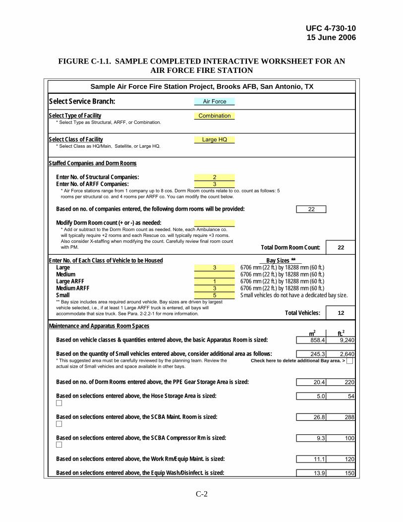
UFC 4-730-10 15 June 2006
C-2
FIGURE C-1.1. SAMPLE COMPLETED INTERACTIVE WORKSHEET FOR AN
AIR FORCE FIRE STATION
Select Service Branch: Air Force
Select Type of Facility Combination
Select Class of Facility Large HQ
Staffed Companies and Dorm Rooms
Enter No. of Structural Companies: 2Enter No. of ARFF Companies: 3
Based on no. of companies entered, the following dorm rooms will be provided: 22
Modify Dorm Room count (+ or -) as needed:
Total Dorm Room Count: 22
Enter No. of Each Class of Vehicle to be HousedLarge 3 6706 mm (22 ft.) by 18288 mm (60 ft.)Medium 6706 mm (22 ft.) by 18288 mm (60 ft.)Large ARFF 1 6706 mm (22 ft.) by 18288 mm (60 ft.)Medium ARFF 3 6706 mm (22 ft.) by 18288 mm (60 ft.)Small 5 Small vehicles do not have a dedicated bay size.
Total Vehicles: 12
Maintenance and Apparatus Room Spaces m2 ft.2
Based on vehicle classes & quantities entered above, the basic Apparatus Room is sized: 858.4 9,240
Based on the quantity of Small vehicles entered above, consider additional area as follows: 245.3 2,640Check here to delete additional Bay area. >
Based on no. of Dorm Rooms entered above, the PPE Gear Storage Area is sized: 20.4 220
Based on selections entered above, the Hose Storage Area is sized: 5.0 54
Based on selections entered above, the SCBA Maint. Room is sized: 26.8 288
Based on selections entered above, the SCBA Compressor Rm is sized: 9.3 100
Based on selections entered above, the Work Rm/Equip Maint. is sized: 11.1 120
Based on selections entered above, the Equip Wash/Disinfect. is sized: 13.9 150
* Add or subtract to the Dorm Room count as needed. Note, each Ambulance co. will typically require +2 rooms and each Rescue co. will typically require +3 rooms. Also consider X-staffing when modifying the count. Carefully review final room count with PM.
* Air Force stations range from 1 company up to 8 cos. Dorm Room counts relate to co. count as follows: 5 rooms per structural co. and 4 rooms per ARFF co. You can modify the count below.
* Select Class as HQ/Main, Satellite, or Large HQ.
Bay Sizes **
** Bay size includes area required around vehicle. Bay sizes are driven by largest vehicle selected, i.e., if at least 1 Large ARFF truck is entered, all bays will accommodate that size truck. See Para. 2-2.2-1 for more information.
Sample Air Force Fire Station Project, Brooks AFB, San Antonio, TX
* Select Type as Structural, ARFF, or Combination.
* This suggested area must be carefully reviewed by the planning team. Review the actual size of Small vehicles and space available in other bays.

UFC 4-730-10 15 June 2006
C-3
FIGURE C-1.2. SAMPLE COMPLETED INTERACTIVE WORKSHEET FOR AN AIR FORCE FIRE STATION (continued)
Based on selections entered above, the Protect. Clothing Laund. is sized: 27.9 300
Based on selections entered above, the EMT Storage Room is sized: 1.1 12
Based on selections entered above, the HAZMAT Equip. Storage is sized: 11.1 120
Based on selections entered above, the Spare PPE Storage is sized: 5.9 64
Select Vehicle Maint./Storage Bay (yes or no): Yes 111.5 1,200
Vehicle Maint./Storage Bay includes Vehicle Maint. Office at: 13.9 150Vehicle Maint./Storage Bay includes Vehicle Maint. Equipment Storage at: 37.2 400
Enter Fire Exting. Inspection (no. of stations): 2 4.5 48
Select Non-Flightline Fire Exting. Maint. (yes or no): Yes 11.1 120
Select Flightline (FL) Fire Exting. Maint. (yes or no): Yes 14.9 160
Select FL Fire Exting. Covered Storage (yes or no): Yes 3.7 40
Yes 16.7 180
Day Room and Residential Area m2 ft.2
Based on no. of Companies entered above, the Day Room is sized: 301.0 3,240
Select Dorm Room bed configuration One Bed
Based on Total Dorm Room Count & bed configuration selected, the Dorm Room Area is sized: 220.7 2,376This provides space for the 'One Bed' configuration (at 10.03 sm (108 sf) per room) for the following:
2 Structural Companies, 3 ARFF Companies, and 0 additional Dorm Rooms (for ambulance or rescue companies or other modifications).
Based on no. of Companies entered above, the Bathrooms are sized: 44.6 480
Based on no. of Companies entered above, the Laundry Room is sized: 22.3 240
Based on no. of Companies entered above, the Fitness Room is sized: 40.6 437
Based on no. of Companies entered above, the Vending Area is sized: 7.4 80
Select Physical Therepy/Sauna (yes or no) Yes 18.6 200
Select Recreation Room (yes or no) Yes 33.4 360
Training and Administrative Area m2 ft.2
Station Officer's Office/ Watch Desk 11.1 120
Based on selections entered above, the Fire Chief's Office is provided: 32.1 345Check here to delete Fire Chief's Office in this HQ station. >
* This Air Force-only item provides space for Spare Flightline Fire Extinguisher Tanks Exterior Covered Storage.
Select Spare FL Fire Exting. Tank Exterior Covered Storage (yes or no):

UFC 4-730-10 15 June 2006
C-4
FIGURE C-1.3. SAMPLE COMPLETED INTERACTIVE WORKSHEET FOR AN AIR FORCE FIRE STATION (continued)
Select Deputy Chief's Office (yes or no): Yes 11.1 120
Based on selections entered above, the Lobby Area is provided: 9.3 100Check here to delete Lobby Area in this HQ station. >
Public toilet (ADA-compliant, unisex) 4.2 45
Based on selections entered above, the Admin. Asst. is provided: 5.9 64Check here to delete Admin. Asst. in this HQ station. >
Based on selections entered above, the Chief's Conf. Room is provided: 11.1 120Check here to delete Chief's Conf. Room in this HQ station. >
Select Asst. Chief/ Shift Supervisor (yes or no): Yes 11.1 120
Select Asst. Chief of Fire Prevention (yes or no): Yes 11.1 120
Enter Inspector(s) Offices (no. of workstations): 2 8.9 96
Select EMS Office (yes or no): Yes 7.4 80
Select HAZMAT/ Safety Office (yes or no): Yes 11.1 120
Select Logistics Office (yes or no): Yes 7.4 80
Select Training Officer Office (yes or no): Yes 9.3 100
Enter Dept. Training Room (no. of people): 24 62.4 672
Dept. Training Room includes Training Room Storage at: 7.4 80
HQ Computer Training/Testing Room (per six testing stations) 17.7 190Check here to delete HQ Computer Training/Testing Room in this station. >
General Admin Storage 7.4 80Check here to delete General Admin Storage in this station. >
IT Room 1.9 20
Select EOC Situation Room* (yes or no): Yes 29.7 320
Enter Reserve Offices (no. of offices): 2 22.3 240
Select Reserve & Active Duty Mob./Depl. Gear Storage: Yes 18.6 200
Select Reserve Firefighter PPE Gear (no. of reservists): 12 Reservists 11.1 120
* If required, enter the no. of workstations desired at this station.
* If required, enter the no. of people to be accommodated/trained (typically this no. is the total on-duty Department staff).
* Note: This is usually only provided in HQ stations that are consolidated with Police/ Security and Emergency Medical Services (EMS).

UFC 4-730-10 15 June 2006
C-5
FIGURE C-1.4. SAMPLE COMPLETED INTERACTIVE WORKSHEET FOR AN AIR FORCE FIRE STATION (continued)
Dispatch m2 ft.2
Enter no. of Dispatch stations (on-duty Dispatchers): 5 89.2 960
Dispatch includes Dispatch Bathroom at: 4.5 48Dispatch includes Dispatch Kitchenette at: 1.9 20Dispatch includes Additional IT Room Space space at: 5.6 60
Select Dispatch Supervisor (yes or no): Yes 5.9 64
Building Totals
Subtotal - Total Net Building Area 2,575.5 27,723
Net-to-Gross factor (modify as necessary): 19% (factor at 0.19) 463.6 5,267
Summary for Air Force Fire Station: TOTAL GROSS BUILDING 3,039.1 32,990Type of Facility = CombinationClass of Facility = Large HQTotal Dorm Room Count = 22Total No. of Apparatus Bays = 9
Site m2 ft.2
Based on selections entered above, Staff Parking is sized: 1,839.4 19,800
Based on selections entered above, Visitor Parking is sized: 209.0 2,250
Based on selections entered above, Bicycle Rack Area is sized: 14.9 160
Based on selections entered above, Site Approach to Apparatus Bays is sized: 1,672.2 18,000
Based on selections entered above, Agent Storage (ARFF) is sized: 27.9 300
Based on selections entered above, Agent Storage (Structural) is sized: 4.5 48
Based on selections entered above, Patio is sized: 32.5 350
TOTAL GROSS SITE SUPPORT 3,800.4 40,908
TOTAL GROSS FACILITY (BUILDING + SITE SUPPORT) 6,839.4 73,898
* The net-to-gross factor accounts for circulation space, mechanical space, and wall thicknesses. The net-to-gross multiplier for Fire Stations may vary from 18% to 22% depending on the size of the Apparatus Room relative to the rest of the facility. Typically, the larger the Apparatus Bay, the lower the multiplier and vice versa. However, carefully consider the entire building configuration before changing the factor from the default setting of 22%.
* This provides space for a Dispatch Supervisor's workstation.

UFC 4-730-10 15 June 2006
C-6
FIGURE C-2.1. SAMPLE COMPLETED INTERACTIVE WORKSHEET FOR AN
ARMY FIRE STATION
Select Service Branch: Army
Select Type of Facility Structural
Select Class of Facility Satellite
Staffed Companies and Dorm Rooms
Enter No. of Structural Companies: 2
Based on no. of companies entered, the following dorm rooms will be provided: 10
Modify Dorm Room count (+ or -) as needed: 2
Total Dorm Room Count: 12
Enter No. of Each Class of Vehicle to be HousedLarge 1 5944 mm (19.5 ft.) by 18288 mm (60 ft.)Medium 1 5944 mm (19.5 ft.) by 18288 mm (60 ft.)Large ARFF 6706 mm (22 ft.) by 18288 mm (60 ft.)Medium ARFF 6706 mm (22 ft.) by 18288 mm (60 ft.)Small 1 Small vehicles do not have a dedicated bay size.
Total Vehicles: 3
Maintenance and Apparatus Room Spaces m2 ft.2
Based on vehicle classes & quantities entered above, the basic Apparatus Room is sized: 217.4 2,340
Based on the quantity of Small vehicles entered above, consider additional area as follows:
Based on no. of Dorm Rooms entered above, the PPE Gear Storage Area is sized: 11.1 120
Hose Storage is typically only provided in Main Stations. If required, check box below.< Check here to add Hose Storage in this Satellite station.
SCBA Maint. Room is typically only provided in Main Stations. If required, check box below.< Check here to add SCBA Maintenance Room in this Satellite station.
SCBA Compressor Rm is typically only provided in Main Sta. If required, check box below.< Check here to add SCBA Compressor Room in this Satellite station.
Based on selections entered above, the Work Rm/Equip Maint. is sized: 11.1 120
Based on selections entered above, the Equip Wash/Disinfect. is sized: 13.9 150
* Add or subtract to the Dorm Room count as needed. Note, each Ambulance co. will typically require +2 rooms and each Rescue co. will typically require +3 rooms. Also consider X-staffing when modifying the count. Carefully review final room count with PM.
* The Army typically builds 1- or 2-company stations, and Dorm Room count relates to Company count as follows: 5 rooms per structural co. and 4 rooms per ARFF co. You can modify the count below.
* Select Class as HQ/Main or Satellite. The Army does not build Large HQ Facilities.
Bay Sizes **
** Bay size includes area required around vehicle. Bay sizes are driven by largest vehicle selected, i.e., if at least 1 Large ARFF truck is entered, all bays will accommodate that size truck. See Para. 2-2.2-1 for more information.
Sample Army Fire Station Project, Ft. Bragg, North Carolina
* Select Type as Structural, ARFF, or Combination.
* This suggested area must be carefully reviewed by the planning team. Review the actual size of Small vehicles and space available in other bays.

UFC 4-730-10 15 June 2006
C-7
FIGURE C-2.2. SAMPLE COMPLETED INTERACTIVE WORKSHEET FOR AN ARMY FIRE STATION (continued)
Based on selections entered above, the Protect. Clothing Laund. is sized: 9.3 100
Based on selections entered above, the EMT Storage Room is sized: 1.1 12
HAZMAT Equip. Storage is typically only provided in Main Sta. If required, check box below.< Check here to add HAZMAT/CBRNE Equip. Storage in this Satellite station.
Spare PPE Storage is typically only provided in Main Sta. If required, check box below.< Check here to add Spare PPE Gear Storage in this Satellite station.
Select Vehicle Maint./Storage Bay (yes or no): No
Vehicle Maint./Storage Bay includes Vehicle Maint. Office at:Vehicle Maint./Storage Bay includes Vehicle Maint. Equipment Storage at:
Enter Fire Exting. Inspection (no. of stations):
Select Non-Flightline Fire Exting. Maint. (yes or no): No
Select Flightline (FL) Fire Exting. Maint. (yes or no): No
Select FL Fire Exting. Covered Storage (yes or no): No
Day Room and Residential Area m2 ft.2
Based on no. of Companies entered above, the Day Room is sized: 120.4 1,296
Select Dorm Room bed configuration Two Beds
Based on Total Dorm Room Count & bed configuration selected, the Dorm Room Area is sized: 156.1 1,680This provides space for the 'Two Beds' configuration (at 13.01 sm (140 sf) per room) for the following:
2 Structural Companies, 0 ARFF Companies, and 2 additional Dorm Rooms (for ambulance or rescue companies or other modifications).
Based on no. of Companies entered above, the Bathrooms are sized: 30.7 330
Based on no. of Companies entered above, the Laundry Room is sized: 7.4 80
Based on no. of Companies entered above, the Fitness Room is sized: 40.6 437
Based on no. of Companies entered above, the Vending Area is sized: 3.7 40
Select Physical Therepy/Sauna (yes or no) No
Select Recreation Room (yes or no) No
Training and Administrative Area m2 ft.2
Station Officer's Office/ Watch Desk 11.1 120
Fire Chief's Office is typically only provided in HQ Stations. If required, check box below.< Check here to add Fire Chief's Office in this Satellite station.
Air Force-only.
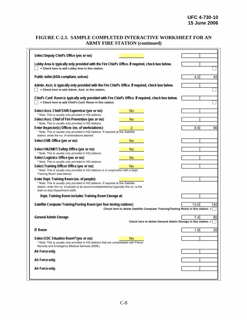
UFC 4-730-10 15 June 2006
C-8
FIGURE C-2.3. SAMPLE COMPLETED INTERACTIVE WORKSHEET FOR AN
ARMY FIRE STATION (continued)
Select Deputy Chief's Office (yes or no):
Lobby Area is typically only provided with the Fire Chief's Office. If required, check box below.< Check here to add Lobby Area in this station.
Public toilet (ADA-compliant, unisex) 4.2 45
Admin. Asst. is typically only provided with the Fire Chief's Office. If required, check box below.< Check here to add Admin. Asst. in this station.
Chief's Conf. Room is typically only provided with Fire Chief's Office. If required, check box below.< Check here to add Chief's Conf. Room in this station.
Select Asst. Chief/ Shift Supervisor (yes or no): No
Select Asst. Chief of Fire Prevention (yes or no): No
Enter Inspector(s) Offices (no. of workstations): 2 8.9 96
Select EMS Office (yes or no): No
Select HAZMAT/ Safety Office (yes or no): No
Select Logistics Office (yes or no): No
Select Training Officer Office (yes or no): No
Enter Dept. Training Room (no. of people):
Dept. Training Room includes Training Room Storage at:
Satellite Computer Training/Testing Room (per four testing stations) 13.0 140Check here to delete Satellite Computer Training/Testing Room in this station. >
General Admin Storage 7.4 80Check here to delete General Admin Storage in this station. >
IT Room 1.9 20
Select EOC Situation Room* (yes or no): No
Air Force-only.
Air Force-only.
Air Force-only. FALSE
* Note: This is usually only provided in HQ stations. If required at this Satellite station, enter the no. of workstations desired.
* Note: This is usually only provided in HQ stations.
* Note: This is usually only provided in HQ stations.
* Note: This is usually only provided in HQ stations or in conjunction with a Dept. Training Room (see below).
* Note: This is usually only provided in HQ stations.
* Note: This is usually only provided in HQ stations.
* Note: This is usually only provided in HQ stations. If required at this Satellite station, enter the no. of people to be accommodated/trained (typically this no. is the total on-duty Department staff).
* Note: This is usually only provided in HQ stations that are consolidated with Police/ Security and Emergency Medical Services (EMS).

UFC 4-730-10 15 June 2006
C-9
FIGURE C-2.4. SAMPLE COMPLETED INTERACTIVE WORKSHEET FOR AN ARMY FIRE STATION (continued)
Dispatch m2 ft.2
Enter no. of Dispatch stations (on-duty Dispatchers):
Dispatch includes Dispatch Bathroom at:Dispatch includes Dispatch Kitchenette at:Dispatch includes Additional IT Room Space space at:
Only available with Dispatch.
Building Totals
Subtotal - Total Net Building Area 669.4 7,206
Net-to-Gross factor (modify as necessary): (factor at 0.22) 120.5 1,585
Summary for Army Fire Station: TOTAL GROSS BUILDING 789.9 8,791Type of Facility = StructuralClass of Facility = SatelliteTotal Dorm Room Count = 12Total No. of Apparatus Bays = 2
Site m2 ft.2
Based on selections entered above, Staff Parking is sized: 1,003.3 10,800
Based on selections entered above, Visitor Parking is sized: 83.6 900
Based on selections entered above, Bicycle Rack Area is sized: 14.9 160
Based on selections entered above, Site Approach to Apparatus Bays is sized: 371.6 4,000
Based on selections entered above, Agent Storage (ARFF) is sized:
Based on selections entered above, Agent Storage (Structural) is sized: 4.5 48
Based on selections entered above, Patio is sized: 13.9 150
TOTAL GROSS SITE SUPPORT 1,491.8 16,058
TOTAL GROSS FACILITY (BUILDING + SITE SUPPORT) 2,281.7 24,849
* The net-to-gross factor accounts for circulation space, mechanical space, and wall thicknesses. The net-to-gross multiplier for Fire Stations may vary from 18% to 22% depending on the size of the Apparatus Room relative to the rest of the facility. Typically, the larger the Apparatus Bay, the lower the multiplier and vice versa. However, carefully consider the entire building configuration before changing the factor from the default setting of 22%.

UFC 4-730-10 15 June 2006
C-10
C-2 SPACE PROGRAM DATA.
The data in Figures C-3.1 and C-3.2 are the bases for the Space Program Interactive Worksheet discussed in Paragraph 2-2 and this Appendix and are provided here for reference only. Do not use these tables to program a Fire Station. The Interactive Worksheet combines this data in the correct manner and incorporates the necessary Service Exceptions—which may not be apparent from these Figures.

UFC 4-730-10 15 June 2006
C-11
FIGURE C-3.1. SPACE PROGRAM DATA (BUILDING) 0.0929
Functional Component m2 ft.2 Standard NotesApparatus, Equip, & Maintenance
Apparatus Bay - Extra Large 108.69 1,170 per truck StationApparatus Bay - Large 86.95 936 per truck StationApparatus Bay - ARFF 122.63 1,320 per ARFF truck StationPPE Gear Storage 0.93 10 per person StationHose Storage 5.02 54 per 52-Hose storage unit DepartmentSCBA Maintenance Room 13.38 144 per four staffed vehicles DepartmentSCBA Compressor Room 4.65 50 per four staffed vehicles DepartmentProtective Clothing Laundry 9.29 100 per staffed vehicle StationEquipment Wash/Disinfection 13.94 150 per room StationWork Room/Equipment Maint. 11.15 120 per room StationVehicle Maint. Equipment Storage 37.16 400 per station As dictated by Installation mission requirementsEMT Storage (incl. locked Meds stor.) 1.11 12 per station StationHAZMAT/CBRNE Equip. Storage 11.15 120 Tech. level / Tier 3 req. DepartmentSpare PPE Gear Storage 5.95 64 per room Department - storage for 30% total crew gearFire Extinguisher Inspection 2.23 24 per inspection station Dept. - dictated by Installation mission requirementsNon-FL Fire Exting. Maint. & Storage 11.15 120 per room Dept. - dictated by Installation mission requirementsFlightline Fire Exting. Maintenance 14.86 160 per station Dept. - dictated by Installation mission requirementsFlightline Fire Exting. Tank Recovery Exterior Covered Storage 3.72 40 per room Dept. - dictated by Installation mission requirements
Spare FL Fire Exting. Tank Exterior Covered Storage 16.72 180 9 sf/tank x 10% of total
tanks As dictated by Installation mission requirements
Vehicle Maintenance/Storage Bay 111.48 1,200 per station Department - AF onlyVehicle Maintenance Office 13.94 150 per office Tied to Vehicle Maintenance Bay
Administrative and TrainingStation Officer's Office/ Watch Desk 11.15 120 per office StationFire Chief's Office 32.05 345 per office DepartmentChief's Conf. Room 11.15 120 per room Department - tied to chief & deputy chiefDeputy Chief's Office 11.15 120 per office Dept. - dictated by Installation mission requirementsLobby Area 9.29 100 per lobby Department - tied to chief & deputy chiefAdmin. Asst. 5.95 64 per office Department - tied to chief & deputy chiefAsst. Chief/ Shift Supervisor 11.15 120 per office Dept. - dictated by Installation mission requirementsAsst. Chief of Fire Prevention 11.15 120 per office Dept. - dictated by Installation mission requirementsInspector(s) Offices 4.46 48 per workstations Department (may be spread-out over several stations)EMS Office 7.43 80 per office Station - dictated by Installation mission requirementsHAZMAT/ Safety Office 11.15 120 per office Dept. - dictated by Installation mission requirementsLogistics Office 7.43 80 per office Dept. - dictated by Installation mission requirementsDept. Training Room 2.60 28 per person Department - total on-duty Fire Department StaffTraining Room Storage 7.43 80 per training room Tied to Department Training RoomTraining Officer Office 9.29 100 per office DepartmentSatellite Computer Training/Testing Roo 13.01 140 per four testing stations Satellite StationHQ Computer Training/Testing Room 17.65 190 per six testing stations HQ StationGeneral Admin Storage 7.43 80 per station StationIT Room 1.86 20 per room StationDispatch 17.84 192 per dispatcher Department - either fire or consolidatedDispatch Supervisor 5.95 64 per workstation Department - tied to dispatchDispatch Bathroom 4.46 48 per fixture (ADA) Department - tied to dispatchDispatch Kitchenette 1.86 20 per kitchenette Department - tied to dispatchAdditional IT Room Space 5.57 60 per room Tied to dispatch
Residential and LivingDay/Training Room 60.20 648 per staffed vehicle Station = kitchen + dining/training + loungeDorm Room with one bed 10.03 108 per room Station = staffed vehicle count + 1/companyDorm Room with two beds 13.01 140 per room Station = staffed vehicle count + 1/companyDorm Room with two fold-up beds 9.29 100 per room Station = staffed vehicle count + 1/companyBathrooms/Showers/Changing 23.23 250 per staffed vehicle StationFitness Room 40.60 437 per station Station - to accommodate 4 working out at one timeLaundry Room 7.43 80 per staffed vehicle Station - 1 washer, 2 dryers, sink, folding tablePhysical Therapy/Sauna 18.58 200 per station Station - dictated by Installation mission requirementsRecreation Room 33.44 360 per station Optional - station = one or two "game units" Vending 1.86 20 per vending machine Station
Other SpacesReserve Offices 11.15 120 per office AF only - dictated by Installation mission requirementsReserve and Active Duty Mobility/ Deployment Gear Storage 18.58 200 per station AF only - dictated by Installation mission requirements
Reserve Firefighter PPE Gear 0.93 10 per person AF only - dictated by Installation mission requirementsEOC Situation Room* 29.73 320 per room Dept. - dictated by Installation mission requirementsPublic toilet (ADA-compliant, unisex) 4.18 45 per room Station
Space Allocation Standard

UFC 4-730-10 15 June 2006
C-12
FIGURE C-3.2. SPACE PROGRAM DATA (SITE) 0.0929
Functional Component m2 ft.2 Standard NotesStaff Parking 41.81 450 per space (incl. circ.) StationVisitor Parking 41.81 450 per space (incl. circ.) StationBicycle Rack Area 14.86 160 per 10-bike Rack StationSite Approach to Apparatus Bays 185.80 2,000 per bay StationAgent Storage (ARFF) 6.97 75 per ARFF truck Station or Department - Foam + 2nd agentAgent Storage (Structural) 4.46 48 per Station (Struct. trucks) Station - Class A FoamPatio 13.94 150 Min. (1 to 2 companies) Station - add 100 sf for 3-4 cos, add 100 sf for > 4 cos.
Space Allocation Standard
UFC 4-730-10 15 June 2006
D-1
APPENDIX D FIGURES
D-1 INTRODUCTION.
Figures D-1 through D-10 do not represent mandatory or even suggested floor plans and layouts. They are provided to illustrate possible means to accommodate the overall needed adjacencies and the room layouts. Note that the written criteria in this UFC take precedence over these figures. If there is any confusion between the text and the figures, follow the guidance outlined in the text.

UFC 4-730-10 15 June 2006
D-2
D-2 HEADQUARTERS STATION. Figure D-1 represents one possible configuration for a small, structural two-company Headquarters Station.
FIGURE D-1. HEADQUARTERS STATION

UFC 4-730-10 15 June 2006
D-3
D-3 LARGE HEADQUARTERS STATION. Figure D-2 represents one possible configuration for a Large Headquarters Station.
FIGURE D-2. LARGE HEADQUARTERS STATION

UFC 4-730-10 15 June 2006
D-4
D-4 APPARATUS BAYS.
The key driver behind the size and configuration of the Apparatus Bays are the truck sizes and the required area around the vehicle footprint. Paragraph 2-2.2.1 gives the standard truck sizes and their relative footprints. The diagrams in Figures D-3.1 through D-3.4 illustrate the required space around each vehicle size class.
Each diagram has three possible configurations: a truck parked between two walls, a truck parked between a wall and another truck, and a truck parked between two other trucks. This is due to the different set-off distances for a wall versus another vehicle.
FIGURE D-3.1. LARGE VEHICLE CLASS

UFC 4-730-10 15 June 2006
D-5
FIGURE D-3.2. MEDIUM VEHICLE CLASS

UFC 4-730-10 15 June 2006
D-6
FIGURE D-3.3. LARGE ARFF (WIDE) VEHICLE CLASS

UFC 4-730-10 15 June 2006
D-7
FIGURE D-3.4. MEDIUM ARFF (WIDE) VEHICLE CLASS
UFC 4-730-10 15 June 2006
D-8
D-5 DEPARTMENT TRAINING ROOM.
Figure D-4 illustrates a possible configuration for the Department Training Room. This room should be sized to accommodate the total on-duty population of the Department.
FIGURE D-4. DEPARTMENT TRAINING ROOM.

UFC 4-730-10 15 June 2006
D-9
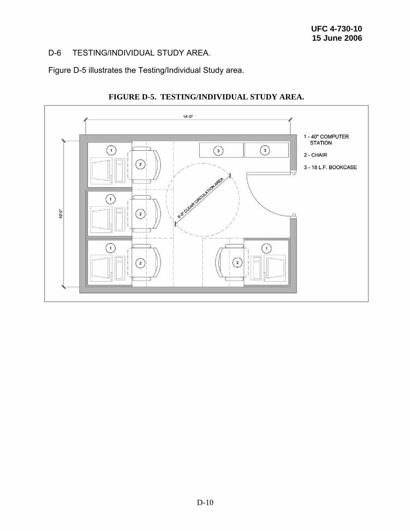
UFC 4-730-10 15 June 2006
D-10
D-6 TESTING/INDIVIDUAL STUDY AREA.
Figure D-5 illustrates the Testing/Individual Study area.
FIGURE D-5. TESTING/INDIVIDUAL STUDY AREA.

UFC 4-730-10 15 June 2006
D-11
D-7 DISPATCH ROOM.
Figure D-6.1 illustrates a small Dispatch Room with two dispatchers and a dedicated toilet. Figure D-6.2 illustrates a larger Dispatch Room with three dispatchers, the Dispatch Supervisor office, the dedicated toilet, and the dedicated Kitchenette.
FIGURE D-6.1. SMALL DISPATCH ROOM.

UFC 4-730-10 15 June 2006
D-12
FIGURE D-6.2. LARGER DISPATCH ROOM.

UFC 4-730-10 15 June 2006
D-13
D-8 DAY ROOM.
The Day Room illustrated in Figure D-7.1 is sized for one staffed vehicle (company). It will grow in modules of this size in direct relationship to the number of companies housed in the station. The dining portion of the space will double as a training area in smaller stations. Figures D-7.2 though D-7.4 illustrate the individual components in greater detail.
FIGURE D-7.1. DAY ROOM
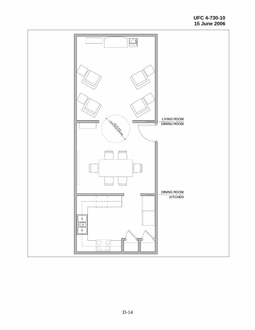
UFC 4-730-10 15 June 2006
D-14

UFC 4-730-10 15 June 2006
D-15
FIGURE D-7.2. DAY ROOM – KITCHEN
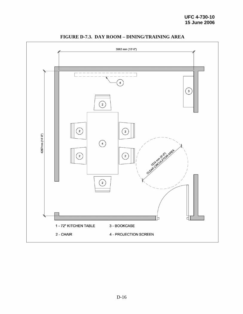
UFC 4-730-10 15 June 2006
D-16
FIGURE D-7.3. DAY ROOM – DINING/TRAINING AREA

UFC 4-730-10 15 June 2006
D-17
FIGURE D-7.4. DAY ROOM – LIVING ROOM AREA

UFC 4-730-10 15 June 2006
D-18
D-9 DORM ROOMS.
Three options are presented as possible layouts for the Dorm Rooms. Figure D-8.1 illustrates a more traditional layout with one bed and two lockers. The bed is shared between the two shifts—with linens stripped after each shift—but each shift firefighter has his or her own locker/wardrobe.
However, there is a trend toward providing separate beds for each shift in order to improve quality of life. Therefore, Figure D-8.2 illustrates this scenario with each shift firefighter having his or her own bed. Figure D-8.3 illustrates a more space efficient approach to providing separate beds by using a fold-up or “Murphy” bed.
FIGURE D-8.1. DORM ROOM WITH ONE BED
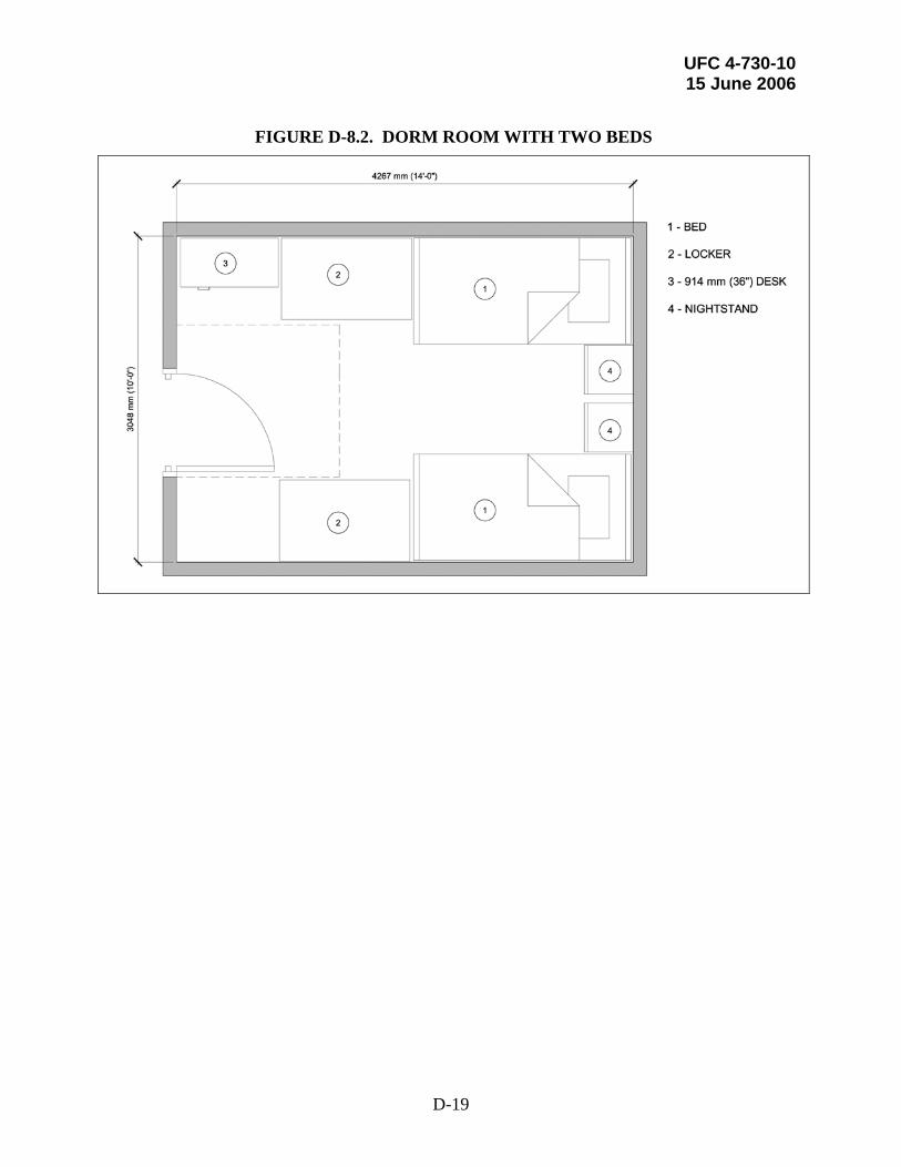
UFC 4-730-10 15 June 2006
D-19
FIGURE D-8.2. DORM ROOM WITH TWO BEDS
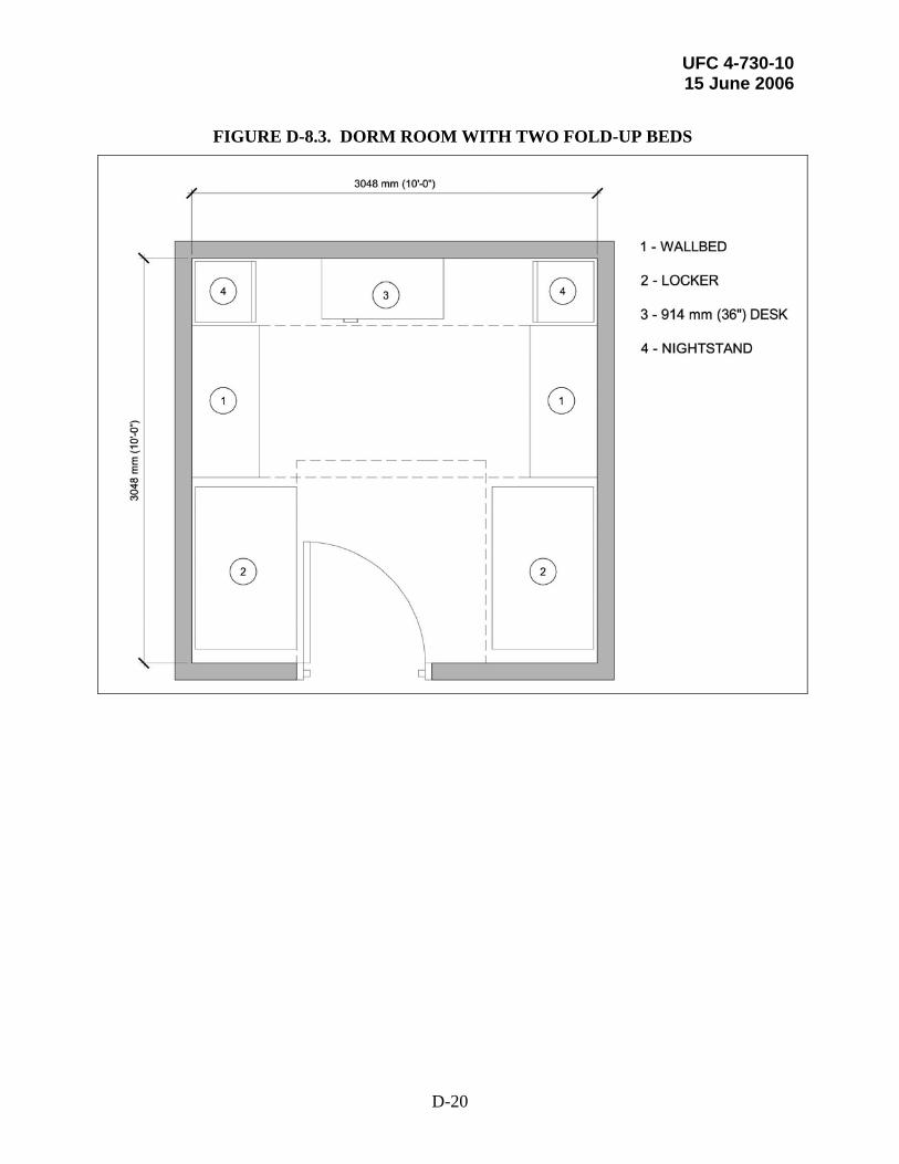
UFC 4-730-10 15 June 2006
D-20
FIGURE D-8.3. DORM ROOM WITH TWO FOLD-UP BEDS
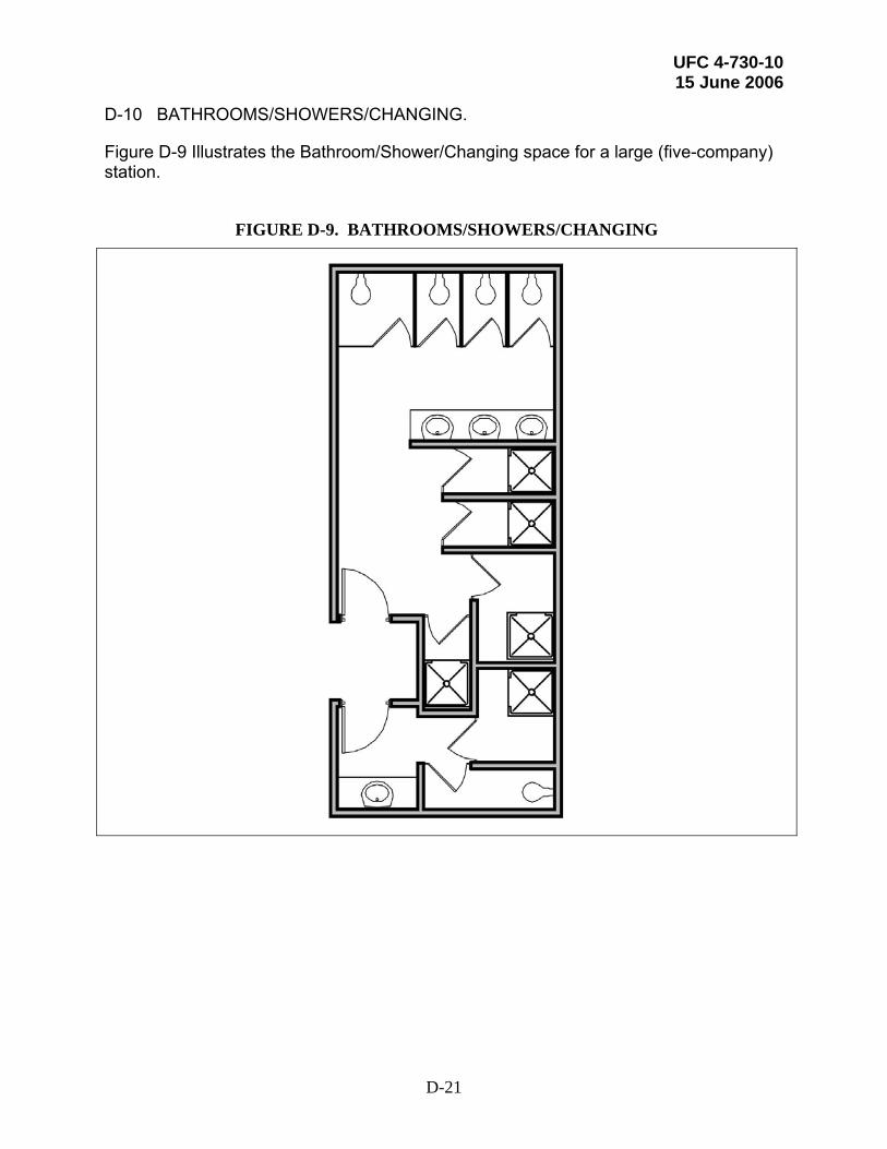
UFC 4-730-10 15 June 2006
D-21
D-10 BATHROOMS/SHOWERS/CHANGING.
Figure D-9 Illustrates the Bathroom/Shower/Changing space for a large (five-company) station.
FIGURE D-9. BATHROOMS/SHOWERS/CHANGING

UFC 4-730-10 15 June 2006
D-22
D-11 FITNESS ROOM.
The Fitness Room illustrated in Figure D-10 is set up to accommodate one company working out at a time. Therefore, it can accommodate four people on aerobic fitness machines and strength training with a Universal machine and free weights.
FIGURE D-10. FITNESS ROOM
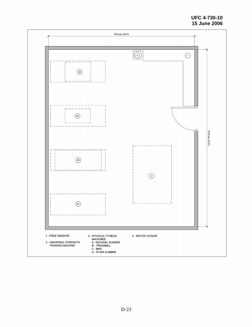
UFC 4-730-10 15 June 2006
D-23


