UFC 3-470-01 Lonworks (R) Utility Monitoring and Control ...

UFC 3-401-01 19 Nov 2008
UNIFIED FACILITIES CRITERIA (UFC) LONWORKS® UTILITY MONITORING
AND CONTROL SYSTEM (UMCS)
APPROVED FOR PUBLIC RELEASE; DISTRIBUTION UNLIMITED

UFC 3-401-01 19 Nov 2008
UNIFIED FACILITIES CRITERIA (UFC)
LONWORKS® UTILITY MONITORING AND CONTROL SYSTEM (UMCS)
Any copyrighted material included in this UFC is identified at its point of use. Use of the copyrighted material apart from this UFC must have the permission of the copyright holder. U.S. ARMY CORPS OF ENGINEERS (Preparing Activity) NAVAL FACILITIES ENGINEERING COMMAND AIR FORCE CIVIL ENGINEER SUPPORT AGENCY Record of Changes (changes are indicated by \1\ ... /1/) Change No. Date Location
This UFC supersedes: UFC 3-401-01FA

UFC 3-401-01 19 Nov 2008
FOREWORD The Unified Facilities Criteria (UFC) system is prescribed by MIL-STD 3007 and provides planning, design, construction, sustainment, restoration, and modernization criteria, and applies to the Military Departments, the Defense Agencies, and the DoD Field Activities in accordance with USD(AT&L) Memorandum dated 29 May 2002. UFC will be used for all DoD projects and work for other customers where appropriate. All construction outside of the United States is also governed by Status of forces Agreements (SOFA), Host Nation Funded Construction Agreements (HNFA), and in some instances, Bilateral Infrastructure Agreements (BIA.) Therefore, the acquisition team must ensure compliance with the more stringent of the UFC, the SOFA, the HNFA, and the BIA, as applicable. UFC are living documents and will be periodically reviewed, updated, and made available to users as part of the Services’ responsibility for providing technical criteria for military construction. Headquarters, U.S. Army Corps of Engineers (HQUSACE), Naval Facilities Engineering Command (NAVFAC), and Air Force Civil Engineer Support Agency (AFCESA) are responsible for administration of the UFC system. Defense agencies should contact the preparing service for document interpretation and improvements. Technical content of UFC is the responsibility of the cognizant DoD working group. Recommended changes with supporting rationale should be sent to the respective service proponent office by the following electronic form: Criteria Change Request (CCR). The form is also accessible from the Internet sites listed below. UFC are effective upon issuance and are distributed only in electronic media from the following source: Whole Building Design Guide web site http://dod.wbdg.org/. Hard copies of UFC printed from electronic media should be checked against the current electronic version prior to use to ensure that they are current. AUTHORIZED BY: ______________________________________ JAMES C. DALTON, P.E. Chief, Engineering and Construction U.S. Army Corps of Engineers
______________________________________JOSEPH E. GOTT, P.E. Chief Engineer Naval Facilities Engineering Command
______________________________________ PAUL A. PARKER The Deputy Civil Engineer DCS/Installations & Logistics Department of the Air Force
______________________________________Dr. GET W. MOY, P.E. Director, Installations Requirements and Management Office of the Deputy Under Secretary of Defense (Installations and Environment)

UFC 3-401-01 19 Nov 2008
i
CONTENTS CONTENTS ..................................................................................................................... i FIGURES .........................................................................................................................ii TABLES ...........................................................................................................................ii CHAPTER 1 INTRODUCTION........................................................................................ 1
1-1 BACKGROUND ................................................................................................ 1 1-2 PURPOSE ........................................................................................................ 2 1-3 SCOPE ............................................................................................................. 3 1-4 APPLICABILITY................................................................................................ 3 1-5 REFERENCES ................................................................................................. 3
CHAPTER 2 UMCS ARCHITECTURE............................................................................ 5 2-1 GENERAL......................................................................................................... 5 2-2 BUILDING CONTROL NETWORK ................................................................... 5
2-2.1 Building Control Network bandwidth .......................................................... 5 2-3 BASEWIDE UMCS NETWORK ........................................................................ 7
2-3.1 General ...................................................................................................... 7 2-3.2 IT group (DOIM) coordination .................................................................... 8 2-3.3 UMCS network bandwidth ......................................................................... 9 2-3.4 BPOC router ............................................................................................ 10 2-3.5 BPOC gateway ........................................................................................ 10
2-4 UMCS SERVERS AND WORKSTATIONS..................................................... 10 2-4.1 General .................................................................................................... 10 2-4.2 LNS server............................................................................................... 11 2-4.3 LNS database file server.......................................................................... 11 2-4.4 Network configuration tool client .............................................................. 12 2-4.5 Monitoring and Control (M&C) software server........................................ 12 2-4.6 Monitoring and Control software client..................................................... 12 2-4.7 Web server .............................................................................................. 12 2-4.8 Browser M&C client ................................................................................. 12 2-4.9 Modems................................................................................................... 13 2-4.10 Data archive and storage......................................................................... 13 2-4.11 Printing..................................................................................................... 13 2-4.12 Computer hardware requirements ........................................................... 13
CHAPTER 3 COMPUTER SOFTWARE ....................................................................... 15 3-1 MONITORING AND CONTROL SOFTWARE ................................................ 15
3-1.1 Number of points, alarms, trends, schedules........................................... 15 3-1.2 Number of clients..................................................................................... 16 3-1.3 GUI – level of graphics desired................................................................ 17 3-1.4 Web-based interface................................................................................ 17 3-1.5 Standard reports ...................................................................................... 18 3-1.6 Demand limiting ....................................................................................... 18 3-1.7 Protocol drivers........................................................................................ 19 3-1.8 User / operator account management ..................................................... 19
3-2 OTHER COMPUTER SOFTWARE................................................................. 19 3-2.1 User account management...................................................................... 19

UFC 3-401-01 19 Nov 2008
ii
3-2.2 CEA-852 configuration server.................................................................. 20 3-2.3 Standard computer software.................................................................... 20 3-2.4 Network configuration tool ....................................................................... 20 3-2.5 DDC UFGS 23 09 23 software................................................................. 21
CHAPTER 4 DRAWINGS ............................................................................................. 22 4-1 UMCS DRAWINGS OVERVIEW .................................................................... 22 4-2 CONTRACT DRAWING SET.......................................................................... 22 4-3 POINTS SCHEDULE ...................................................................................... 23
4-3.1 Overview.................................................................................................. 23 4-3.2 Responsibilities........................................................................................ 23 4-3.3 Points schedule description and instructions ........................................... 23
4-4 ALARM CONTACT AND ALARM ROUTING GROUP SCHEDULES ............. 24 4-4.1 Alarm contact schedule............................................................................ 24 4-4.2 Alarm routing group schedule .................................................................. 25
4-5 COMPUTER EQUIPMENT SCHEDULE......................................................... 26 CHAPTER 5 PROJECT IMPLEMENTATION................................................................ 29
5-1 INTRODUCTION ............................................................................................ 29 5-2 PLANNING...................................................................................................... 29 5-3 PROJECT SCOPE.......................................................................................... 29 5-4 UMCS AND INTEGRATION SERVICES PROCUREMENT CONSIDERATIONS .................................................................................................. 29 5-5 UMCS DESIGN............................................................................................... 31
5-5.1 General .................................................................................................... 31 5-5.2 Prepare contract documents.................................................................... 31 5-5.3 Coordinate with IT Group (DOIM) ............................................................ 31 5-5.4 M&C software requirements .................................................................... 33
APPENDIX A GLOSSARY ............................................................................................ 34
FIGURES Figure 2-1. UMCS and DDC System Architecture........................................................... 7
TABLES Table 3-1: Number of Points and Trends in Typical Systems........................................ 16 Table 4-1. Example Alarm Contact Schedule................................................................ 25 Table 4-2. Example Alarm Routing Group Schedule (for Building 123)......................... 25 Table 4-3. Computer Equipment Schedule. .................................................................. 28

UFC 3-401-01 19 Nov 2008
1
CHAPTER 1
INTRODUCTION
1-1 BACKGROUND Designers, installers, and operation and maintenance (O&M) staff have struggled with the complexities and incompatibilities of multi-vendor building automation direct digital control (DDC) systems almost since they were introduced in the 1980’s. DDC systems are routinely designed and procured on a building-by-building or sub-system by sub-system basis, most notably for heating, ventilating, and air-conditioning (HVAC) systems. In the absence of specifications and criteria for Open systems, Government procurement rules that require competitive bidding make it extremely difficult if not impossible to procure new DDC systems that are compatible with existing ones and that are also compatible with a basewide or campus-wide supervisory system. In the absence of sole-source procurement, new but incompatible DDC systems result at best in inefficiencies and at worst in complex and non-functioning systems. This is a problem with system-to-system data sharing and is a problem where multiple individual systems need to communicate with a supervisory monitoring and control (front-end) system such as a Utility Monitoring and Control System (UMCS) specified by UFGS 25 10 10. This inability to interoperate is a result of Closed systems due to vendor-specific proprietary elements. In contrast, Open DDC systems are now available. An Open DDC system is characterized by the ability for any qualified entity to readily modify, operate, upgrade, and perform retrofits on the DDC system. An Open system:
• Permits multiple devices from multiple vendors to readily exchange information. • Provides the capability to easily replace any device with another device procured
from multiple sources.
• May have proprietary components within devices, but these proprietary components must be a small percentage of the overall device.
• May have fees associated with use of certain components.
In short, an Open system is one (integrated, multi-vendor) system where there is no future dependence on any one Contractor or controls vendor. Open communications and data sharing between multi-vendor systems and with a third party supervisory system is necessary to achieve effective system operation. Some of the benefits and capabilities of Open multi-vendor DDC systems include:
• Competitive procurement, most notably at the building and sub-system level.

UFC 3-401-01 19 Nov 2008
2
• An operator workstation/user interface that provides for the same look and feel
for monitoring and control regardless of which vendor’s DDC system or sub-system an operator is viewing. As a result, system operators need only become proficient with one user interface.
• An operator workstation/user interface (software) that provides for management
of base-wide system operations such as: remote alarm reporting; remote scheduling (on/off control); remote set point override; data logging and reports; energy management including load shedding; utilities monitoring/measurement for the purpose of monitoring energy performance contracts; and initial diagnosis of service calls. As a result, through a single user interface, system operators and managers are afforded the means to efficiently and effectively manage base-wide operations.
• Whole-building approach to systems integration. This includes the efficient inter-
connection of HVAC control sub-systems. For example, terminal unit equipment, such as VAV boxes can be readily interfaced to the servicing air handler to provide a call for cooling. In addition, the whole-building approach provides the capability for integrating non-HVAC sub-systems such as fire and security.
• Lays the groundwork for establishment of a non-proprietary and openly
accessible ‘point-database’ in support of communications-network management requirements. The Open database approach further insulates the government from the possibility of single vendor lock-in and the necessity of proprietary procurement.
1-2 PURPOSE This document describes an Open-systems approach for the design of a Utility Monitoring and Control System (UMCS) in accordance with UFGS 25 10 10 “Utility Monitoring and Control System (UMCS)”. A UMCS is a supervisory management system that may be used to achieve utility cost, energy, and manpower savings for electrical systems, heating, ventilating, and air-conditioning, water and sanitary sewer systems, process equipment, lighting, chillers, boilers, and other utility systems and equipment. The UMCS is intended to openly interoperate with systems and subsystems installed in accordance with UFGS 23 09 29 “LonWorks® Direct Digital Controls for HVAC and Other Local Building Systems” and accompanying UFC 3-410-02. The Open systems approach specified by UFGS 25 10 10 and UFGS 23 09 23 and described in this document is based on the use of LONWORKS
® technology, in particular the use of the LONWORKS
® Network Services (LNS®) network operating system to provide an infrastructure for network tools and UMCS applications and the use of ANSI/CEA-709.1-B (sometimes referred to as LonTalk®; hereafter CEA-709.1) to

UFC 3-401-01 19 Nov 2008
3
ANSI/CEA-852 (hereafter CEA-852) routers to provide connectivity between the UMCS network and the building control network. The UMCS is designed to work with Open building-level systems and is intended to be as Open as possible, but may have proprietary (closed) elements. It’s important to note that the government’s definition of a proprietary system is one that requires sole-source procurement for system modifications, and the UMCS as specified in UFGS 25 10 10 and this UFC does not.
1-3 SCOPE This document describes the design of an Open UMCS including hardware, software, and networking.
1-4 APPLICABILITY This UFC and accompanying UFGS 25 10 10 'LonWorks Utility Monitoring and Control System' are for use on all USACE and AFCESA projects. The NAVFAC standard is to use BACnet for its DDC communication protocol and NAVFAC systems should use UFGS 23 09 23.13 20 'BACnet Direct Digital Control Systems for HVAC'. NAVFAC allows the use of LonWorks for upgrades and additions to legacy systems. At the discretion of and with approval from the assigning government agency (such as the responsible Corps of Engineers District), the design of the UMCS may deviate from the standards defined in this UFC. When deviating from the guidance, systems based on an Open communications protocol are recommended and proprietary procurement or single-vendor systems are discouraged.
1-5 REFERENCES American National Standards Institute/Consumer Electronics Association:
• ANSI/CEA-709.1-B, Control Network Protocol Specification, 2002 • ANSI/CEA-709.3, Free-Topology Twisted-Pair Channel Specification, 1998. • ANSI/CEA-852, Tunneling Component Network Protocols Over Internet Protocol
Channels, 2001. Headquarters, U.S. Army Corps of Engineers (HQUSACE)
• UFGS 25 10 10, LONWORKS® UTILITY MONITORING AND CONTROL SYSTEM (UMCS), 2008.
• UFGS 23 09 23, LONWORKS® DIRECT DIGITAL CONTROL FOR HVAC AND OTHER LOCAL BUILDING SYSTEMS, 2008.
UFC 3-401-01 19 Nov 2008
4
• UFC 3-410-02FA, LONWORKS® DIRECT DIGITAL CONTROL FOR HVAC AND OTHER LOCAL BUILDING SYSTEMS, 2008.
LonMark International
• LonMark Interoperability Guidelines, LonMark Application-Layer Interoperability Guide version 3.4, 2005 and LonMark layer 1-6 Interoperability Guide version 3.4, 2005.
• LonMark XIF Guide, LonMark Device Interface File Reference Guide version 4.401, 2005.
• LonMark SNVT Master List, LonMark Standard Network Variable Type • (SNVT) Master List version 12, 2003. • LonMark SCPT Master List, LonMark Standard Configuration Property Type
(SCPT) Master List version 12, 2003. • LonMark Standard Enumeration Master List, LonMark Standard Enumeration
Master List version 12, 2003.

UFC 3-401-01 19 Nov 2008
5
CHAPTER 2
UMCS ARCHITECTURE
2-1 GENERAL As illustrated in Figure 2-1 a basewide system consists of a UMCS (specified by UFGS 25 10 10) connected to one or more building-level DDC systems (specified by UFGS 23 09 23). The network architecture consists of a basewide IP network and one or more building-level TP/FT-10 networks. DDC UFGS 23 09 23 refers to the building-level TP/FT-10 network as the Building Control Network (BCN). A building point of connection (BPOC) provides an interface between the IP and BCN networks. Generally, the UMCS will be a basewide system, but it may initially consist of only one (or few) building control networks with the capability of being expanded to include additional building systems where multiple building control networks can be connected to a single UMCS via a BPOC router at each building.
2-2 BUILDING CONTROL NETWORK As illustrated in Figure 2-1 DDC UFGS 23 09 23 specifies the Building Control Network (BCN) and requires the use of CEA-709.1 communications protocol over a TP/FT-10 network connected in a doubly-terminated topology. The BCN consists of a backbone with one or more local control buses connected to it via routers. This produces a logically flat network in the building where each node can communicate directly with any other node without the intervention of another controller.
2-2.1 Building Control Network bandwidth In rare cases, the TP/FT-10 network installed under DDC UFGS 23 09 23 may have insufficient bandwidth to support the UMCS data requirements. In this case the single BPOC and single TP/FT-10 backbone in the building will need to be replaced with multiple BPOCs and the TP/FT-10 backbone segmented into multiple backbones, each feeding a dedicated BPOC. However, because this will involve additional IP networking, this separation is performed by the UMCS contractor so as to avoid the need for coordination between the UFGS 23 09 23 contractor and the DOIM. The UMCS contractor is required to perform a network bandwidth calculation for each Building Control Network that is to be integrated so as to determine if this segmentation is necessary. A typical heavily loaded building control network might be performing the following activities:

UFC 3-401-01 19 Nov 2008
6
• Transmitting every point in the building indicated on Points Schedules as being available to the UMCS in response to polling requests at 15-minute intervals (for trending at UMCS).
• Transmitting five points to the UMCS in response to polling requests at 2-second
intervals. • Transmitting 100 points to the UMCS in response to polling requests at 5-second
intervals.
• Transmitting occupancy commands from the UMCS to every system schedule sequence in a one-minute interval.
• Transmitting occupancy override commands from the UMCS to every system
schedule sequence in a one-minute interval. A normally loaded control network is characterized as one performing the following activities simultaneously:
• Transmitting every point in the building indicated on Points Schedules as requiring a trend to the UMCS in response to polling requests at 15-minute intervals (for trending at UMCS).
• Transmitting 50 points to the UMCS in response to polling requests at 5-second
intervals. • Transmitting occupancy commands from the UMCS to every system scheduler
sequence in a one-minute interval. Assuming 3 packets per point that is transmitted, an estimate of bandwidth utilization can be obtained by simply adding up all the transmissions. The building media communicates at 78 kbps which translates to roughly 250 packets per second before it starts to saturate. The specification requires that the network bandwidth be below 75 packets per second for a normally loaded network and 150 packets per second for a heavily loaded network.

UFC 3-401-01 19 Nov 2008
7
Figure 2-1. UMCS and DDC System Architecture
2-3 BASEWIDE UMCS NETWORK
2-3.1 General As specified by UMCS UFGS 25 10 10 and as illustrated in Figure 2-1 the building point of connection (BPOC) provides an interface between the BCN (specified in DDC UFGS 23 09 23) and the Internet Protocol (IP) network. This supports inter-building communication and also serves as the communications link between the building-level controls and the UMCS computers. The basewide UMCS network is based on Internet Protocol (IP) Ethernet standard IEEE 802.3. This network will support the data transmission requirements of the UMCS including initial setup and configuration of the network devices along with post-setup day-to-day intercommunication of all network devices.
Basewide ANSI 709.1B over IP Network (EIA-852) >=100Mbps
BPOCRouter
RTR
RTR
RTRMore devices
and/or ‘subnets’
RTR
More devices. No more RTRs or
RPTRs
RTR
More devices. No more RTRs
or RPTRs
AN
SI 7
09.1
B o
ver T
P/FT
-10
(IAW
AN
SI 7
09.3
)
One or more workstation running: -GUI Clients -Network Management Tool Clients -Web Clients (optional)
One or more servers running: -LNS Server -Network Management Tool -Graphical User Interface (GUI) -Monitoring and Control Software -Web Server (optional)
UFG
S 23 09 23
UFGS 25 10 10
RTRnon-ANSI 709.1legacy system
BPOCGateway
RTR=RouterBPOC=Building Point Of ConnectionCircle = node (ANSI-709.1 device)

UFC 3-401-01 19 Nov 2008
8
2-3.2 IT group (DOIM) coordination The creation of a basewide UMCS network will need to be coordinated with the local Information Technology (IT) group such as the Directorate of Information Management (DOIM). The intent of this coordination is to address network access, management, and security issues including:
• Support of UMCS IP network requirements • Network security (and certification) requirements (including Networthiness and
DIACAP) An IP network is needed to connect the BPOC(s), computer servers, computer workstations, and printers. The intent is to share the existing basewide IT LAN operated by the DOIM and to use a virtual LAN (VLAN). There may be exceptional cases where the UMCS contractor will need to install a separate IP network, but this approach is strongly discouraged and the requirements will need to be defined and coordinated with DOIM to obtain this network. Another uncommon case will be where the UMCS network needs to be extended to a remote site where there is no existing IP network. In these cases, the designer should coordinate with the installation and DOIM to determine the best approach. DOIM will likely rule some approaches unacceptable due to security issues. Some possible approaches are:
• DOIM extends existing basewide network. This is probably the best solution, but may be too costly.
• Contractor extends basewide network. This may also be too costly. In this case,
DOIM likely will take control of the network extension. • Use of modems (dial-in/dial-out) to connect the remote site over phone lines.
This is probably the least expensive (assuming the remote site has phone lines), but will offer the poorest performance and may not be approved by DOIM.
• Wireless (RF). This is a good compromise between cost, performance, and
security.
• Free Space Optical. This is another wireless connection using point-to-point lasers or LEDs. It offers good performance and excellent security (equivalent to a wired network), but is often more costly than RF. It may be the only solution if the DOIM will not allow a RF link.
Within the buildings, DOIM will need to provide IP drops and IP addresses in support of UMCS requirements as shown by the designer on a UMCS Computer Equipment

UFC 3-401-01 19 Nov 2008
9
drawing as described in CHAPTER 4 DRAWINGS. In rare cases, DOIM will need to provide additional IP drops and IP addresses in support of UMCS requirements in the case where the building control network needs to be split among several BPOCs as determined by the UMCS contractor’s Building Control Network Bandwidth Calculations. DOIM coordination is further described in CHAPTER 5 PROJECT IMPLEMENTATION.
2-3.3 UMCS network bandwidth A properly designed UMCS Network will require minimal network bandwidth as compared to many IT applications and compared to the bandwidth typically available on a modern basewide IT backbone. The designer must exercise care in selecting data transmission parameters in the building or at the workstation to prevent excessive data requests although the low-speed of the building network will tend to limit possible problems of excessive network usage to saturation of the building network. The CEA-709.1 network in the building will most likely have a data transmission rate of 78.8 Kilo-Bits-Per-Second (kbps). The basewide IT network will almost certainly have a data transmission rate of at least 100 Mega-Bits-Per-Second (Mbps) and may have a rate exceeding 1000 Mbps. In this case, it would take over 1000 buildings, each sending data at 78.8 kbps, to fill the backbone network operating at 100 Mbps. UMCS applications do not require transmission of large quantities of data in seconds or less. A typical heavily loaded UMCS might be performing the following activities:
• Trending 1000 points at 15-minute intervals. This is less than 1 kbps. • Trending (for loop tuning) 20 points at 2-second intervals. This is less than 1
kbps. • Viewing 500 points (via workstations) with a 2 second update interval. This will
require on the order of 20-40 kbps. Note that a typical graphic will contain 20 points or less -- 500 points assumes many users of very complex graphics.
• During periods of demand limiting, the front-end application may need to send
load shedding commands to 10,000 controllers in a 1 minute interval. This will require on the order of 200-400 kbps, which is still negligible compared to 100 Mbps.
• Viewing of web-based graphics via a browser. The loading of the graphic itself is
a one-time event when the page is opened. This is a high-bandwidth event (but it happens once, and it's the sort of event that IT networks are designed to handle). The actual update and transfer of data requires minimal bandwidth.

UFC 3-401-01 19 Nov 2008
10
2-3.4 BPOC router The Building Point of Connection (BPOC) is the demarcation point between the UMCS and the building-level network. It defines the division of responsibility between the UMCS Contractor and the building-level control system Contractor. The contractual responsibilities of the UMCS Contractor and the building-level Contractor will be project-specific, but in general the building-level Contractor is responsible for installing the building-level network and LonWorks controls while the UMCS Contractor is responsible for connecting the building-level network to the UMCS. The BPOC is specified in UMCS UFGS 25 10 10. It is a CEA-709.1 TP/FT-10 to IP Router that converts building-level communication protocol to CEA-852 (CEA-709.1 tunneled over IP), and vice versa. The BPOC performs routing of CEA-709.1 packets over an Ethernet network in accordance with IEEE 802.3. The BPOC router supports two basic functions:
• It manages communications traffic by routing designated CEA-709.1 packets between different local building-level networks and the UMCS Servers/Workstations.
• It permits UMCS Servers/Workstation access to individual nodes/controllers in
support of network and device configuration using an LNS compatible network tool.
2-3.5 BPOC gateway The sole function of a BPOC gateway is to convert proprietary vendor-specific non-CEA-709.1 building-level protocol data to CEA-709.1 as SNVTs, and vice versa. Gateways are used to support legacy (existing) building-level DDC systems. Gateways are not intended to serve as an interface in new-project DDC systems, unless specifically approved by the government design authority. A gateway is sometimes referred to as a communications bridge.
2-3.5.1 Other BPOCs Other BPOCs are prohibited unless specifically approved by the design authority
2-4 UMCS SERVERS AND WORKSTATIONS
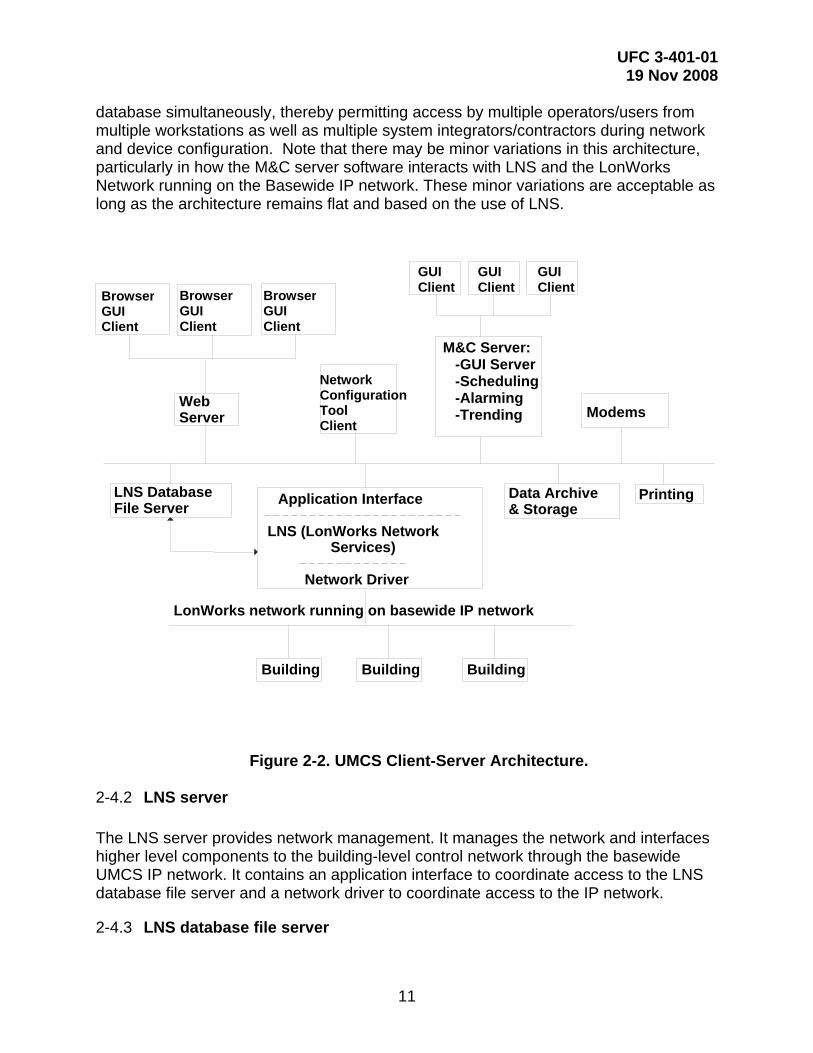
2-4.1 General The UMCS front-end hardware and software consists of a number of distinct logical functional blocks, as shown in Figure 2-2. UMCS Client-Server Architecture. Figure 2-2 is based on LonWorks Network Services (LNS®) network operating system. LNS provides an infrastructure for network tools and UMCS applications helping to ensure interoperability of these tools and applications by providing Open data access services for applications. The client-server architecture allows multiple clients to access the LNS
UFC 3-401-01 19 Nov 2008
11
database simultaneously, thereby permitting access by multiple operators/users from multiple workstations as well as multiple system integrators/contractors during network and device configuration. Note that there may be minor variations in this architecture, particularly in how the M&C server software interacts with LNS and the LonWorks Network running on the Basewide IP network. These minor variations are acceptable as long as the architecture remains flat and based on the use of LNS.
2-4.2 LNS server The LNS server provides network management. It manages the network and interfaces higher level components to the building-level control network through the basewide UMCS IP network. It contains an application interface to coordinate access to the LNS database file server and a network driver to coordinate access to the IP network.
2-4.3 LNS database file server
LonWorks network running on basewide IP network
Building
Application Interface
LNS (LonWorks Network Services)
Network Driver
LNS Database File Server
Web Server Modems
Data Archive & Storage
Printing
Building Building
BrowserGUI Client
BrowserGUI Client
BrowserGUI Client
GUI Client
GUI Client
GUI Client
M&C Server: -GUI Server -Scheduling -Alarming -Trending
Network ConfigurationTool Client
Figure 2-2. UMCS Client-Server Architecture.

UFC 3-401-01 19 Nov 2008
12
The LNS database resides on a file server. The LNS Database stores an ‘image’ of the network configuration/definitions for all LonWorks nodes including the standard network variable types (SNVTs). It is possible to have multiple LNS databases for a single UMCS; a single LNS Server can manage multiple databases. The LNS database file server is an integral part of LNS, but it may reside on hardware separate from the LNS Server such as a separate file server.
2-4.4 Network configuration tool client A Network configuration tool client is a software package that serves as a user interface to the LNS server. This tool will likely reside on the same hardware as the LNS server, but may also be run from other computers anywhere on the IP network, or, with the proper hardware interface, from a building-level network.
2-4.5 Monitoring and Control (M&C) software server The M&C server, sometimes referred to as a UMCS server, manages, stores, and executes UMCS applications and operations such as scheduling, alarming, trending, and other global functions. This server also serves graphic user interface (GUI) pages for M&C clients These functions are logically distinct, but are ordinarily contained in a single software package. This software package interacts with the Application Interface in the LNS server, but may reside on a computer separate from the LNS server.
2-4.6 Monitoring and Control software client An M&C client is a client of the M&C server in the client-server architecture. It has a graphical user interface and functions as an operator workstation to allow user/operator access to the M&C server as it performs UMCS workstation-type functions. Depending on the software vendor, the M&C client may be inseparable from the M&C Server where one software package includes both. In this case multiple clients requires the purchase of multiple M&C server packages. Other vendors offer clients at reduced cost (sometimes via a licensing arrangement) where one M&C server package can support multiple clients running on other computers. M&C clients typically require that vendor-specific software be loaded on the client computer. This software is sometimes referred to as thick-client software.
2-4.7 Web server A web server serves up web pages via the Internet to browser-based clients, but not all UMCS vendors provide these web services. The web server may reside on the same computer as the LNS server, but more likely is located on one or more separate PCs. Web services are not specified in UFGS 25 10 10 or UFGS 23 09 23.
2-4.8 Browser M&C client A browser-based client provides web-based Internet access to web pages served up by a Web Server. These (thin) clients perform the same function as M&C clients but rely

UFC 3-401-01 19 Nov 2008
13
only on established Internet browser technologies such as Firefox and Internet Explorer. Unlike an M&C client, a browser client ordinarily does not require vendor-specific (thick client) software on the computer receiving the web pages.
2-4.9 Modems A modem may be used for dial-out access to a pager in order to generate alphanumeric pages, typically to send important alarms. While dial-in modems are possible, their use is generally prohibited by DOIM as their use entails large security risks. In some cases, where the basewide IP network does not extend to remote buildings/sites, modems may be needed to extend the UMCS network. This use of modems must be coordinated with DOIM.
2-4.10 Data archive and storage The front end system provides long-term storage of programs and data largely in support of the GUI server functions.
2-4.11 Printing The UMCS supports printing services including one or more ink jet, laser, and possibly color printers. For line-by-line printing of alarms, a dot-matrix can be used.
2-4.12 Computer hardware requirements UFGS 25 10 10 specifies minimum hardware requirements for computer servers and computer workstations. Many of these requirements are dependent on the application to be run on the server. The reason for this is the rapid advancement in computer hardware and the corresponding increase in software requirements. Rather than specify a requirement that would quickly become obsolete (for example “CPU shall be at least 1 GHz Pentium III or equivalent”) or excessive for the application, the requirements are based on the stated requirements of the software to be provided.
2-4.12.1 Server hardware The UMCS is dependent on the operation of several server processes. In particular, servers related to the LNS server (possibly including a remote file server for the database) are needed for the UMCS to function. For this reason, UFGS 25 10 10 places specific requirements on hardware that may be used for a computer server:
• RAID (Redundant Array of Inexpensive Disks) is a commonly used computer technology for protecting data against disk drive hardware failure. A computer running either a RAID-1 or RAID-5 array (there are other RAID levels that offer this functionality, but RAID-1 and RAID-5 are the most common) will be able to continue uninterrupted operation even after the catastrophic failure of one of the disk drives. (After a drive has failed, the computer should be shut down and the defective drive replaced soon. Until the drive is replaced, the data is vulnerable to
UFC 3-401-01 19 Nov 2008
14
an additional drive failure.) In many cases RAID drives can be hot-swapped such that a defective drive can be replaced without shutting down the computer.
• Redundant power supplies are another commonly used and specified computer
technology to guard against computer hardware failure. The computer is designed with two (or more) power supplies any one of which is sufficient to operate the computer. In case of a power supply failure, the computer will continue to operate on the remaining supply(s). In addition, the hot swap capability means the defective power supply can be replaced without shutting the server down. Redundant power supplies should be plugged into separate UPS devices on separate circuits. Even if a breaker or UPS fails, the server can still be powered from the other breaker/UPS.
The DOIM is an excellent source of information on these and other computer hardware technologies that may be used to increase the reliability of computer server hardware.
2-4.12.2 Workstation hardware The UMCS is not dependent on the availability of clients to carry out its key operational functions therefore there are no additional requirements for computer hardware beyond what is typically procured for a standard desktop computer. <END OF CHAPTER

UFC 3-401-01 19 Nov 2008
15
CHAPTER 3
COMPUTER SOFTWARE
3-1 MONITORING AND CONTROL SOFTWARE The Monitoring and Control (M&C) software uses a client-server model. The “essential” software runs on a server computer and provides “services” to clients. For example, the program that polls devices for trend data and stores it on a computer hard drive runs on the M&C server machine. Operator WorkStation (OWS) clients would connect to that server software to work with trends (set up, edit, delete, view, graph, etc.). In many cases, the client software may run on the same machine as the server software. In these cases the computer must be a server class machine not a client class machine. For example, the computer running the M&C software can probably be used as an OWS (client to the M&C software).
3-1.1 Number of points, alarms, trends, schedules M&C software packages have upper capacity limits on the number of points, alarms, etc. that the package can accommodate. In addition, most packages have license limits less than the maximum supportable by the software. UFGS 25 10 10 requires the designer to specify (via bracketed option) the number of system points, alarms, trends, and occupancy schedules required for the installation. Points/alarms. For the M&C software, each point equates to a SNVT that the M&C Software must input or output. The number of points can be counted on the Points Schedules for the system by looking at each row of the Points Schedules:
• If there is an X in the M&C Display or Trend columns or if an alarm is shown, add a point. Note that it only counts as one point, no matter how many columns have X’s because the same SNVT is used for trending, displays and generating alarms.
• If there is an X in the override column, add a point
Trends. For the number of trends, consideration must be given to the fact that in the long term, trends are not needed on every system. Trends are generally used during the commissioning/warranty phase and for problem diagnosis. The trend numbers given below represent a compromise between what is set up initially (things marked as trended on the Points Schedule) and what would be a fairly moderate amount of long-term trending. Schedules. For schedules, a conservative estimate would be one schedule per system (AHU, or AHU and its associated VAV boxes) and one schedule per X number of stand-alone terminal units (one that is not served by an AHU), where X would need to be determined from the design (but a very conservative number would be one schedule for every three terminal units).

UFC 3-401-01 19 Nov 2008
16
Table 3-1 summarizes the number of points and long-term trends in the typical/example systems based on the defaults shown in the Points Schedule drawings. Where there are two numbers for a system, the first number is for the AHU itself and the number below it is an additional number per zone. Note that these are sample numbers for reference only as the Point Schedules may have been edited since this table was generated.
Table 3-1: Number of Points and Trends in Typical Systems System Points Trends
All Air Small Package Unit 10 1 Heating and Ventilating Unit 23 1
Single Zone with Heating and DX Coils Single Zone with Heating and Cooling Coils Single Zone with Dual Temperature Coils
32 2
Single Zone with Heating and Cooling Coils and Return Air Bypass 35 2
Single Zone with Humidity Control 37 2 38 4 Dual Duct with Return Fan
Multizone with Return Fan 6 1 32 4 Multizone with Hot Deck Bypass with Return Fan 8 1
VAV with Return Fan (not including VAV boxes) 53 6 VAV with Reheat 12 1
Fan Powered VAV Box with Reheat 13 1 Cooling Only VAV Box 10 1
Perimeter Radiation 9 0 Unit Heater and Cabinet Unit Heater 11 0
Gas-Fired Infrared Heater 8 0 Dual Temperature Fan Coil Unit 12 1
Hydronic Heating Hot Water from Distributed Steam Converter 13 1
Hydronic Heating Hot Water from Distributed HTHW Converter 14 1
Hydronic Heating Hot Water from Single-Building Boiler 16 1
Hydronic Dual-Temperature System, with Steam Heat Exchanger and Chilled Water 23 2
Hydronic Dual-Temperature System, with HTHW Exchanger and Chilled Water 23 2
Hydronic Secondary with Constant Speed Pumping 3 1 Hydronic Secondary with Variable Speed Pumping 6 1
3-1.2 Number of clients An important decision that the designer must make in coordination with the installation (customer) is the number of client seats desired. Most M&C software will be licensed as
UFC 3-401-01 19 Nov 2008
17
a single server but with varying numbers of client (these may be referred to as client “seats”). The number of clients may be given as a maximum number and as a maximum number of simultaneous connections. In this case, there may be (for example), 12 client machines licensed to run the client software, but only 4 clients permitted to access the M&C server at any one time. In other cases, the vendor may offer a site license that would permit the installation to have as many clients as it wishes (though there may still be restrictions on how many clients can connect simultaneously). For other vendors, particularly those with web clients, there will not be any restrictions on how many machines can run the client software. However, there may still be restrictions on how many can connect simultaneously. Of course, regardless of the licensing scheme, there will be performance limitations on the number of clients a single M&C server can handle before its performance degrades unacceptably.
3-1.3 GUI – level of graphics desired The term Graphical User Interface (GUI) is somewhat a misnomer. An operator thinks of a GUI as providing a graphical representation of systems (i.e. pictures) whereas vendors use the term GUI in the same sense that Microsoft® describes Excel® as providing a GUI for a spreadsheet (tool bars, pull down menus, mouse driven, etc.). This can potentially lead to a Contractor providing a GUI without graphics. Most vendors offer some level of graphical representation of systems; whether these graphics are included in the base-level product offering depends on the vendor. Most vendors also offer animation, 3-D graphics, links to AutoCAD or PDF documents, and links to GIS (Geographical Information Systems). UFGS 25 10 10 requires a moderate level of graphics including building floor plans and either one-line or 3-D representation of HVAC systems. These requirements can and should be edited in accordance with the specific installation requirements (often found in the Installation Design Guide (IDG)). It’s important to consider the effect that detailed graphics have on the performance of the user interface; the more complex the graphic, the longer it will take for the page to load (particularly for web-based clients). 3-D graphics or graphics with a great deal of animation should be avoided unless the installation specifically requests them.
3-1.4 Web-based interface UFGS 25 10 10 does not specify/require a web-based M&C Software package. Web-based interfaces have both pros and cons.
PROS: • The biggest benefit to web-based systems is the flexibility they provide since any
computer with a web browser can become a M&C Software client. The need for this flexibility is pretty much the only reason to require web-based M&C clients. Note that many installations don’t really require this flexibility; they only need a

UFC 3-401-01 19 Nov 2008
18
few M&C clients and it’s easy enough to just install client software on those machines.
• Web based clients may be cheaper since there is the possibility of using existing
computer hardware and software for the clients. Dedicated clients probably/may require the purchase of additional/dedicated hardware and software.
• While web servers introduce a number of security risks, the risks are well
established and understood by the DOIM. It may be that while the actual risk with a web interface is higher than that for a non-web based interface, the perceived risk will be less with the web interface.
• Familiar technology for DOIM. DOIM may be better able to support web clients
than non-web clients. This may offer security advantages as well; while in theory, a non-web based client may offer better security, the web client (as implemented) may be more secure because DOIM better understands the security issues.
CONS: • There are security issues since any machine can be a client. The increased
access opportunities also increase the opportunities that someone who isn’t supposed to access the system can. It’s also easier to ‘hack’ a machine that is serving web pages as it is already partially exposed.
• DOIM will quite probably place additional restrictions on machines serving web
pages. There is a popular misconception that if the system is web based and can be accessed via any browser it is automatically ‘Open’ (in the sense of interoperability). This isn’t true. Web-based systems from multiple vendors can (and generally do) have a common enough “look-and-feel” for an operator to be comfortable thinking of them as a single system. On the other hand, slight differences in presentation that wouldn’t confuse an operator will break interoperability between two systems. When it comes to sharing information, to an operator “75.0 degrees F” and “25 deg. C” represent the same thing, but to a computer expecting “75.0”, “25 C” is probably not decipherable.
3-1.5 Standard reports UFGS 25 10 10 requires an extensive list of reports. Coordinate with the installation and edit these requirements as needed.
3-1.6 Demand limiting UFGS 25 10 10 requires that the M&C Software be capable of performing electrical demand limiting. In addition, the use of real time pricing data can be required as well. While the installation may not implement demand limiting immediately, trends in energy

UFC 3-401-01 19 Nov 2008
19
pricing and government energy targets make the eventual use inevitable. Most vendors provide demand limiting, however, it may be difficult to get demand limiting incorporating real time pricing at this time. It is recommended that real time pricing not be required unless specifically needed by the installation.
3-1.7 Protocol drivers UFGS 25 10 10 permits the use of software protocol drivers as a means of integrating non-CEA-709 systems. Use of software protocol drivers for any other purpose is strictly forbidden. In particular, the M&C software must communicate with CEA-709 systems exclusively via CEA-852.
3-1.8 User / operator account management There are two common approaches to account management for M&C software:
• The M&C software maintains its own set of usernames and passwords. • The M&C software does not maintain a separate user database. Instead, it
determines permissions according to the user currently logged in (in the Microsoft® Windows® sense) to the computer.
An advantage to using the Microsoft® Windows® accounts is that the Operating System (OS) probably has a more secure mechanism for managing user accounts and passwords. A disadvantage is that each user of the software must have a separate login to the machine and changing users requires logging out and logging back into the machine. Use of accounts other than Windows accounts (i.e. where the M&C software maintains a separate list of user/operator accounts) will raise additional security concerns in the DIACAP/Networthiness process and should be avoided where possible.
3-2 OTHER COMPUTER SOFTWARE
3-2.1 User account management While other software may have user accounts and privileges similar to the M&C software, more often the full capabilities of the software will be available to anyone with access to the software. For example, (in general) anyone who can run the network configuration tool (or device programming software as specified in DDC UFGS 23 09 23) will be able to perform any operation allowed by that software. For this reason, care should be taken when assigning Microsoft® Windows® user accounts to machines that contain this software to prevent an unauthorized user from being able to damage the system.

UFC 3-401-01 19 Nov 2008
20
3-2.2 CEA-852 configuration server The CEA-852 network connecting the BPOCs with the M&C server runs over the basewide IP network. Essentially, every BPOC has a point-to-point connection with every other BPOC and with the M&C server. These connections could be configured manually. However the specification requires the use of a configuration server to manage this network. This configuration server is a software package that runs on computer server hardware. Typically, this software package will be installed on the same server as the main M&C software or LNS server.
3-2.3 Standard computer software Computers specified by UFGS 25 10 10 will be general purpose computers running (with very rare exceptions) some version of Microsoft® Windows®. To protect these computers, anti-virus software needs to be installed on them. The M&C software will generate trends and reports where in order to view and edit these documents the Contractor should provide an office automation software package. The DOIM will almost certailnly have base-wide standards for both the anti-virus software and the office automation package. The UFGS 25 10 10 Contractor should be required to provide software in compliance with the base-wide standards.
3-2.4 Network configuration tool The network configuration tool serves several purposes:
• Configures device bindings (communication) between controllers • Sets device configuration properties (things like PID settings and setpoints),
generally through the use of a LNS plug-in So that the installation can become proficient with one tool and to avoid multiple tools, UFGS 25 10 10 requires the tool be provided as a part of UMCS contract rather than asking for a tool from each building Contractor. Any LNS-based tool will work with any DDC UFGS 23 09 23 compliant building control network. Two key requirements of the network configuration tool are:
• That it read and write LNS databases. Some tools use a different format internally, then allow you to export to LNS. Use of these tools creates the potential for inconsistencies between their internal format and LNS that may lead to problems down the road.

UFC 3-401-01 19 Nov 2008
21
• The tool must be able to run LNS plug-ins. Without this capability, device configuration will be much more difficult, since plug-ins provide a user-friendly interface for device configuration data.
3-2.5 DDC UFGS 23 09 23 software Note that DDC UFGS 23 09 23 software specified under DDC UFGS 23 09 23 will generally be installed on machines that are considered part of the UMCS. In particular, Microsoft® Windows® accounts will need to be established for machines containing GPPC programming tools.

UFC 3-401-01 19 Nov 2008
22
CHAPTER 4
DRAWINGS
4-1 UMCS DRAWINGS OVERVIEW This chapter describes typical UMCS design drawing requirements and how to edit them to be project-specific. CHAPTER 5 PROJECT IMPLEMENTATION provides an overview of the project-specific drawing requirements detailed in this chapter. Example drawings are available from the following source:
https://eko.usace.army.mil/fa/besc/ The drawings were originally developed using AutoCAD® and every effort was made to ensure compliance with A/E/C CADD Standard Release 2.0.
4-2 CONTRACT DRAWING SET A set of Contract drawings may consist of:
• Points Schedule(s) • Points Schedule - Contractor Instructions • Alarm Contact Schedule • Alarm Routing Group Schedule • Computer Equipment Schedule
As part of the editing process to make the sample drawings project-specific, the sample drawings use the following conventions:
• Entries required of the designer are shown bracketed as: [ ___ ] • Entries required of the Contractor are shown bracketed as: < ___ > • Spaces where no entry is ordinarily required contains a tilde: “ ~ “ (equivalent to
an “n/a” or null value)
The bracketed [ ___ ] designer entries in the sample drawings are provided as a guide to the designer. These entries must be verified or changed by the designer. When editing the drawings, delete the brackets after verifying/providing the entry. Contract drawings should contain no designer brackets [ ___ ]. Do not leave cells blank. Instead, show the tilde ("~") to indicate a null value or that no further entry is required.

UFC 3-401-01 19 Nov 2008
23
4-3 POINTS SCHEDULE
4-3.1 Overview The most common task to be performed under UFGS 25 10 10 is integration of one or more DDC systems (installed in accordance with UFGS 23 09 23) into a UMCS (installed in accordance with UFGS 25 10 10) and the designer must include Points Schedule drawing(s) in the UMCS contract package to specify integration requirements. These Points Schedules should be obtained from completed projects (as-built submittals) where DDC UFGS 23 09 23 was used.
4-3.2 Responsibilities The DDC system designer is responsible for the initial set of Points Schedule entries including alarm limits and operator display and override requirements. The DDC contractor uses the Point Schedule to install the controls and submits an updated and completed Points Schedule as an as-built drawing. The UMCS designer reviews these as-built drawings and updates the M&C display, trend, and override entries as needed and uses these drawings as design drawings for the UMCS. The UMCS contractor uses this drawing for the integration of the building system into the UMCS and submits a final Points Schedule as an as-built drawing.
4-3.3 Points schedule description and instructions Points Schedules are described in the DDC UFC 3-410-02. A summary is provided here. Columns in the Points Schedule labeled “M&C” pertain to functionality to be provided by the Monitoring and Control (M&C) Software specified in UFGS 25 10 10. These columns include SNVTs accessible to the UMCS from the building DDC system installed in accordance with UFGS 23 09 23. When the DDC system is integrated into the UMCS, the "M&C" columns specify functionality configured at the M&C Software by the UMCS Contractor.
1) M&C DISP REQ'D column: an "x" in this column indicates that the graphical display for this system must display the value of this point.
2) M&C TREND REQ'D column: an "x" in this column indicates that the Contractor
will create and set up an 'initial' trend for this point at the M&C software. Note that any point with an associated SNVT can be trended and the intent of showing an "x" in the Schedule for an 'initial' trend might be for testing or commissioning purposes.
3) M&C OVRD REQ'D column: an "x" in this column indicates that the Contractor
must provide M&C override capability for this point. In the case of 'System reset button' (RST-BUT) an "x" indicates that the M&C software shall provide the

UFC 3-401-01 19 Nov 2008
24
capability to reset the system after shutdown due to an alarm. Use caution in specifying this capability.
4) ALARM PRIORITY column: This column shows the priority for alarms as either
Critical (CRIT) or Informational (INFO). As specified in UFGS 25 10 10, critical alarms remain in alarm until acknowledged by a UMCS operator and the alarm condition no longer exists. Informational alarms shall remain in alarm until the alarm condition no longer exists or until the alarm is acknowledged. Show the alarm priority for each alarm.
5) M&C ROUTING column: This column shows the name of the Alarm Routing
Group that is to be used for each alarm handled by the UMCS as further described in paragraph 4-4. The entry in this column corresponds to an Alarm Routing Group as shown on the Alarm Routing Schedule drawing. Show the Alarm Routing Group name that is to be used for this alarm. Where:
• If there is an existing UMCS, coordinate with the installation and show the
M&C Routing name from the existing UMCS Alarm Routing Group name set.
• If there is not an existing UMCS, coordinate with the installation to create an alarm routing contact schedule and an Alarm Routing Group Schedule. Use the Alarm Routing Group schedule to show the M&C Routing name.
4-4 ALARM CONTACT AND ALARM ROUTING GROUP SCHEDULES The ALARM CONDITION column in each Points Schedule defines alarm condition(s) for individual points. The M&C software monitors these points (via their associated SNVTs) and performs alarm notification and routing functions. Two schedules help to define alarm requirements: a Contact Schedule that lists the individuals to be paged and/or emailed and an Alarm Routing Group Schedule that provides the list of alarm routes to be used by all alarms. Note that there is a separate Schedule and requirements for 'redundant critical alarm handling' which is a building-level DDC UFGS 23 09 23 function/requirement, independent of the UMCS, and therefore is not part of nor specified under UMCS UFGS 25 10 10 projects.
4-4.1 Alarm contact schedule The Alarm Contact Schedule defines alarm recipient information. The designer will complete this schedule or the designer may specify that the Contractor shall complete this schedule. In either case, customer/user input will be required to identify appropriate entries as illustrated in Table 4-1 and the Contractor must submit this schedule.
UFC 3-401-01 19 Nov 2008
25
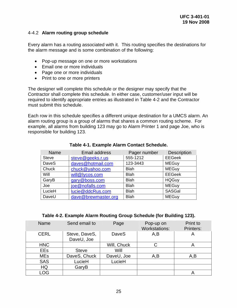
4-4.2 Alarm routing group schedule Every alarm has a routing associated with it. This routing specifies the destinations for the alarm message and is some combination of the following:
• Pop-up message on one or more workstations • Email one or more individuals • Page one or more individuals • Print to one or more printers
The designer will complete this schedule or the designer may specify that the Contractor shall complete this schedule. In either case, customer/user input will be required to identify appropriate entries as illustrated in Table 4-2 and the Contractor must submit this schedule. Each row in this schedule specifies a different unique destination for a UMCS alarm. An alarm routing group is a group of alarms that shares a common routing scheme. For example, all alarms from building 123 may go to Alarm Printer 1 and page Joe, who is responsible for building 123.
Table 4-1. Example Alarm Contact Schedule. Name Email address Pager number Description
Steve [email protected] 555-1212 EEGeek DaveS [email protected] 123-3443 MEGuy Chuck [email protected] Blah MEGuy Will [email protected] Blah EEGeek GaryB [email protected] Blah HQGuy Joe [email protected] Blah MEGuy LucieH [email protected] Blah SASGal DaveU [email protected] Blah MEGuy
Table 4-2. Example Alarm Routing Group Schedule (for Building 123). Name Send email to Page Pop-up on
Workstations: Print to Printers:
CERL Steve, DaveS, DaveU, Joe
DaveS A,B A
HNC Will, Chuck C A EEs Steve Will MEs DaveS, Chuck DaveU, Joe A,B A,B SAS LucieH LucieH HQ GaryB
LOG A

UFC 3-401-01 19 Nov 2008
26
On the Points Schedule, the M&C Routing column will list the name of the Alarm Routing Group to use. For example, an alarm with the routing group HNC will be routed as follows:
• No emails notifications will be sent • Will and Chuck will be paged using the pager numbers from the Contact
Schedule • A pop-up message will be displayed on workstation C (as shown on the
Computer Equipment Schedule) • A message will be printed on printer A (as shown on the Computer Equipment
Schedule)
4-5 COMPUTER EQUIPMENT SCHEDULE The Computer Equipment Schedule lists primary computer equipment including servers, workstations, printers, and BPOCs. The designer will develop this schedule although the Contractor, depending upon project specific requirements, is responsible for certain entries. Schedule entries include:
• Reference: The designer completes this field as an equipment identifier. • Hardware: The designer completes this field for each:
o Computer: Server, Desktop (Workstation) or Laptop (Workstation) o Printer: Alarm (continuous feed is default), Laser (B&W), or Color o BPOC: Router (CEA-709.3 to IP) or Gateway
• Hardware Provided By: The designer completes this field. For example, in the
case of a client workstation existing government-provided equipment may be used.
• Hardware Location: The designer completes this field. In all cases, the existence
of or need for an IP network drop should be checked/verified. Where network drops are required, the designer should coordinate with the IT group or DOIM. In addition, in the case of a BPOC, the designer should verify that the Building Control Network (BCN) TP/FT-10 cabling extends to the BPOC location (Note that the BCN is specified under UFGS 23 09 23). Similarly, for a gateway, verify that the proprietary control network cabling extends to the gateway location.
• Network Name: The Contractor completes this field, possibly with DOIM input, to
indicate the network name of the computer. • IP Address: The Contractor completes this field, possibly with DOIM input.

UFC 3-401-01 19 Nov 2008
27
• Media Size or Monitor Size: Filled out by designer. Either the display monitor size for computers or non-standard media size for printers. It is assumed all printers can print on 8.5” x 11” portrait mode media. List any other media sizes required here.
• Monitoring and Control Software Functions: Designer lists required functionality
for the listed computer. For servers, this is the functionality that must be hosted by the server. For workstations this is the functionality that must be useable from the workstation.
• Network Configuration Tool: The designer completes this field to show
workstations and laptops that shall be provided with network configuration tool (NCT) software.
• Sheet Number: The Contractor completes this field. If there is a UMCS riser
diagram, this may be used to indicate a reference to the sheet number (of that riser diagram) on which the equipment is shown.

UFC 3-401-01 19 Nov 2008
28
Table 4-3. Computer Equipment Schedule.
UFC 3-401-01 19 Nov 2008
29
CHAPTER 5
PROJECT IMPLEMENTATION
5-1 INTRODUCTION This chapter describes the planning and design of a UMCS project and is largely constrained to the case where a new UMCS is being designed and includes only initial integration services as opposed to integration services as part of the expansion or modification of an existing UMCS. This is discussed in more detail in paragraph 5-4.
5-2 PLANNING In addition to the guidance contained in this UFC the design should be based on site-specific planning documents. Designs must be accomplished in accordance with the customer’s site specific requirements such as the Installation Design Guide (IDG), Master Planning documents, and the UMCS/DDC Implementation Plan. To help obtain maximum benefit of Open DDC systems, designers should encourage their customers to develop a UMCS/DDC Implementation Plan as recommended in Engineering Construction Bulletin (ECB) 2007-8 and described in ERDC/CERL Technical report TR-07-16 'IMCOM LONWORKS® Building Automation Systems Implementation Strategy' available at: http://www.cecer.army.mil/techreports/ERDC-CERL_TR-07-16/ERDC-CERL_TR-07-16.pdf.
5-3 PROJECT SCOPE The designer must assess the project specific requirements and tailor the design accordingly. This includes consideration of the procurement methodology as discussed in paragraph 5-4 and the applicable DDC systems, as specified in UFGS 23 09 23, that are to be interfaced as part of the UMCS project.
5-4 UMCS AND INTEGRATION SERVICES PROCUREMENT CONSIDERATIONS The design of a UMCS and use of UFGS 25 10 10 can result in procurement of either a:
• UMCS without integration services, • UMCS with integration services, or • Integration services only
Where integration services are to be included, the designer, in coordination with the customer, must consider both the overall method by which these services will be accomplished and the specific details of the contracting and funding mechanisms. Even in the case where no integration is performed with the initial UMCS procurement, integration services will be required in the future as additional buildings are added to the UMCS. Therefore, the scope and contracting mechanism should be identified early. There are four basic methods to obtain integration services as described below:

UFC 3-401-01 19 Nov 2008
30
• In house system integration services. Ideally the installation will have an in-house system integrator (SI) who is a single-entity or specific individual responsible for the integration of all new buildings into the UMCS. The in-house SI might be a government employee or Contractor under a long term services contract. This method has the advantage of ensuring that the integrator is familiar with the UMCS and the installation requirements. It also ensures a consistent look-and-feel to the operator interface. This approach would also commonly include system maintenance.
• IDIQ contractor for integration services. Another good option is to have a long
term IDIQ contract specifically for integration services. This approach has advantages similar to the in house approach above. This approach would commonly include system maintenance and upgrades.
• Case-by-Case integration with a combined building and integration services
contract. In this case, a single contract is issued which includes both UFGS 23 09 23 (DDC) and UFGS 25 10 10 (UMCS) and the building DDC contractor is also responsible for integration to the UMCS front end. The original UMCS vendor may be able to perform integration cheaper than other vendors which can result in cost savings or in a competitive advantage on the contract. (Note that the government owns sufficient tools and rights to the front end to allow any contractor familiar with the front end to perform the integration.) Extra care should be taken to ensure that the interface between building and front end (primarily the points schedules) is fully documented. Finally, ensuring consistent results between integration vendors can be difficult in this case.
• Case-by-Case integration with separate building DDC and integration contracts.
Again, the original UMCS vendor may be able to perform integration cheaper than other vendors which can result in cost savings or in a competitive advantage on the integration contract (but probably not on the building contract). Again, ensuring consistent results between vendors can be difficult.
There are several contracting mechanism suitable for each of the above integration approaches. Some include:
• Local contracting office • Energy Savings Performance Contracting (ESPC) • Corps District IDIQ Contracts • Corps Center of Expertise IDIQ Contracts
Each of these mechanisms has advantages and disadvantages depending on the integration method chosen. Further information is available in ERDC/CERL Technical Report TR-07-16 'IMCOM LONWORKS® Building Automation Systems Implementation Strategy' at https://eko.usace.army.mil/fa/bas/.

UFC 3-401-01 19 Nov 2008
31
5-5 UMCS DESIGN
5-5.1 General The designer is responsible for designing the UMCS using the symbols, abbreviations, and acronyms designated in this guidance. This design responsibility requires producing a design package consisting of a specification and a set of drawings. Although many implementation details are left to the Contractor, the designer shall not depend on the UMCS Contractor or vendor for the preparation of the contract package. The resultant project-specific specifications will require the UMCS Contractor to produce shop drawings, schedules, test plans, test procedures, and other documents showing the application of products to implement the UMCS design. The specification further requires the Contractor to define and install the interface to the building-level CEA-709.1 communications network in a manner that is consistent with performance requirements defined in the specification and that the Contractor test the UMCS to show that the UMCS functions as designed.
5-5.2 Prepare contract documents The Contract package will include drawings:
• Points Schedule(s) • Points Schedule - Contractor Instructions • Alarm Contact Schedule • Alarm Routing Group Schedule • Computer Equipment Schedule • Demand Limit Schedule (optional)
5-5.3 Coordinate with IT Group (DOIM) It is crucial to coordinate IT communications network usage and requirements with those responsible for IT such as the Directorate of Information Management (DOIM). Refer to Chapter CHAPTER 2 UMCS .
Two key areas requiring coordination are DIACAP and Networthiness. These topics are discussed briefly below. For further details refer to ERDC/CERL Technical Report TR-07-16 'IMCOM LONWORKS® Building Automation Systems Implementation Strategy' at https://eko.usace.army.mil/fa/bas/. In particular, the breakout of responsibilities between the contractor, installation DPW, and DOIM for the DIACAP process are unclear at this point and the reader should refer to the ERDC/CERL website for the latest information.
5-5.3.1 DIACAP DOD regulations require that any Army information system go through the DOD Information Assurance Certification and Accreditation Process (DIACAP). DIACAP is

UFC 3-401-01 19 Nov 2008
32
intended to identify and provide information security protections commensurate with risk and magnitude of harm resulting from unauthorized access, use, disclosure, disruption, modification or destruction of information and information systems. There are two general approaches to meeting this requirement: 1) have a DIACAP package for the UMCS and 2) have the UMCS covered under another DIACP (typically a DIACAP packaged submitted by the DOIM for the basewide LAN). The latter approach is simpler but may not always be possible If a separate DIACAP package is needed, the general process flow is as follows:
• Secure funding for the process. Several steps will require outside assistance. • Prepare and submit a System Identification Profile (SIP) for the UMCS. This
document will describe the UMCS and several key player in the process. One key player that must be identified will be the ACA (Agent of the Certification Authority) who will play the role of the commissioning agent for validation of compliance with IA controls. The ACA will almost certainly require funding for this step.
• Determine which IA (Information Assurance) controls the UMCS must comply
with. For purposes of DIACAP, the UMCS will be considered MAC III (not critical for the warfighter) and Sensitive (not classified, but not public either).
• Document compliance with IA controls and develop a get-well-plan where the
system fails to comply. • Submit documentation and request an ATO (Authority to Operate)
It is strongly recommended that the DOIM be heavily involved in the DIACAP process. In addition, it is advisable that the ACA be retained at an early stage to assist with compliance with controls. At present, it is not possible for installation “Y” to refer to the DIACAP package for installation “X” even if they have the same M&C software vendor. Each installation must pursue its own DIACAP package. Prior to beginning the DIACAP process, the installation should check with the local DOIM to determine if the system can be covered under an existing DIACAP. In this case, the installation will generally submit documentation to the DOIM similar to the system identification profile described above.
5-5.3.2 Networthiness Army regulations require that any system connected to the basewide LAN have a certificate of Networthiness. Unlike DIACAP, installations may reference a pre-existing Networthiness certificate developed by another installation as long as the M&C software vendor is the same. If the selected vendor’s M&C software has not received a certificate of Networthiness, the installation will have to obtain one. Further information is available at the Networthiness website https://www.us.army.mil/suite/kc/6655214.

UFC 3-401-01 19 Nov 2008
33
5-5.3.3 Computer Administration and Maintenance It may be advantageous (or required at some installations) for DOIM to manage day-to-day operation of computer servers including backups, account management, operating system and security updates, and other administration. At the very least, DOIM will likely have specific requirements for computers connected to the basewide line.
5-5.3.4 BPOC and other building hardware Any hardware connected to the IP network must possess a valid certificate of Networthiness. This includes hardware installed in the building such as CEA 852 routers, building level gateways (from non-709.1 protocols to CEA 852 Lon/IP), and other devices that route non-709 networks to the IP network. The last devices will require special attention since they involve routing non-CEA-852 protocols over the basewide network. Details of the operation of these devices (used when integration of non-709.1 systems is via a protocol driver at the M&C server) must be coordinated with the DOIM early in the process since DOIM may disallow use of such a device for building integration.
5-5.4 M&C software requirements As part of the Monitoring and Control software functionality, the designer will specify graphics display requirements, password assignments and permissions, alarm points, alarm types, alarm notification and routing, initial schedule overrides (if any), initial trends (if any), demand limiting (if any), and desired reports.

UFC 3-401-01 19 Nov 2008
34
APPENDIX A GLOSSARY
10Base-T 100Base-T 100Base-FX 1000Base-T 1000Base-SX 1000Base-LX 10GBase-T
Ethernet media and communication speeds. The number is communication speed in Megabits per second (Mbps) or Gigabits per second (Gbps). “T” is twisted pair wire (usually Cat-5 or better), while “FX”, “SX”, and “LX” are fiber optic cable. Note that 10 Gigabit Ethernet is (as of 2006) an IEEE standard and 100 Gigabit Ethernet is in development.
AGC Application Generic Controller. A controller that comes from the factory with a limited built-in application. It is programmed for the application (VAV box, fan coil, etc.). It can be programmed through an LNS plug-in. It can be thought of as a cross between an ASC and GPPC. These controllers should be certified by Lon Mark. An AGC has a fixed program ID.
ASC Application Specific Controller. A controller that has a built-in, fixed program to execute a sequence for a specific hardware system, e.g. a VAV box controller. An ASC has a fixed program ID.
Building Point of Connection (BPOC)
The BPOC is the point of connection between the UMCS network backbone (an IP network) and the building control network backbone. The hardware at this location that provides the connection is referred to as the BPOC Hardware. In general, the term "BPOC Location" means the place where this connection occurs, and "BPOC Hardware" means the device that provides the connection. Sometimes the term "BPOC" is used to mean either and its actual meaning (i.e. location or hardware) is determined by the context in which it is used.
Closed The opposite of Open. A standard/protocol/specification where important details of its implementation are not available to all interested parties. Closed standards are closely controlled by the developing party and implementation of devices based on them is generally limited to a small number of vendors.
Device A piece of hardware. See also 'Node'.
DDC Direct Digital Control, defined as control consisting of microprocessor-based controls with the control logic performed by software.
DDE Dynamic Data Exchange, an interprocess communication (IPC) system built into the Macintosh®, Microsoft® Windows®, and OS/2® operating systems. DDE enables two running applications to share the same data.

UFC 3-401-01 19 Nov 2008
35
DHCP Dynamic Host Configuration Protocol is a protocol for automatically assigning IP configuration information to clients from a central server.
FTP File Transfer Protocol is a common protocol used on the Internet for sending files.
Gateway A device (usually a combination of software and hardware) that connects networks using different communication protocols so that information can be passed from devices on one network to the other. Gateways perform protocol conversion to translate this information from one protocol to another.
GPPC General Purpose Programmable Controller. A controller that can be programmed to run any (within hardware limits) sequence and can be set up as a controller for different hardware systems. Changes to the program result in a different Program ID.
GUI Graphical User Interface. A program interface that takes advantage of the computer's graphics capabilities to make the program easier to use. A true GUI includes formats for representing text and graphics.
HMI Human-Machine Interface. The means by which an operator interacts with an automation system, often a GUI.
HTTP HyperText Transfer Protocol, is the underlying protocol used by the World Wide Web. HTTP defines how messages are formatted and transmitted, and what actions Web servers and browsers should take in response to various commands.
Interoperability The ability to integrate products from multiple vendors into flexible, functional systems without the need to develop custom hardware, software, or tools.
UFC 3-401-01 19 Nov 2008
36
Interoperable This is closely related to Open standards and refers to the level of difficulty of integrating components (or systems) from multiple vendors into a single system. Interoperability needs to be considered from the perspective of hardware installation (will the parts physically fit and interconnect?), communications (do the devices “speak the same language”?), configuration and programming (is the same software tool used for different vendor components?), maintainability (do the components have similar maintenance procedures and requirements?), and operation (do the components have similar functionality/sequences and utilize the same operator interface?). Open standards enhances/encourages interoperability because it allows multiple vendors to utilize a common standard. A caveat: In many (if not all cases), when vendors use the term interoperable, they do not mean interchangeable (in the sense of swapping out a VAV box for an identical VAV box).
IP Internet Protocol. IP is a protocol on the Internet and is concerned with addressing and routing of data packets from their origin to the destination. Many other protocols are used in the Internet (TCP, HTTP, etc), but IP is the key protocol the others run on top of.
LAN Local Area Network, is a network for transferring data between computers or other digital devices.
LNS® LonWorks Network Service, is the database architecture that resides on the computer attached to the LonWorks Network that is used to install and manage the Network. LNS is a database that can be accessed by any LNS-based Network Configuration Tool and by multiple users simultaneously.
LON Local Operating Network. Also used as a shorthand reference to the term LonWorks.
LonTalk® A networking protocol developed by Echelon Corporation and recognized by ANSI/CEA as ANSI/CEA-709.1-B. LonTalk implements layers 1-6 of the OSI reference model.
LonWorks® A networking platform (created by Echelon Corporation) that provides solutions to numerous problems of designing, building, installing, and maintaining control networks.
LonWorks Router A piece of equipment that allows ANSI/CEA-709.1-B communication and routing of network variables over an ANSI/CEA-709.1-B network. See “Router”
LonWorks LON to IP Router
A piece of equipment that allows ANSI/CEA-709.1 communication and routing of network variables over IP. Also known as an ANSI/CEA-852 router. See “Router”.
UFC 3-401-01 19 Nov 2008
37
Network A group of devices (computers, controllers, or other digital units) that are connected by communication facilities, such as twisted-pair cabling, coaxial cable, fiber-optic cable, or wireless means.
Network Configuration Tool
Software used to perform network management functions such as adding, removing or relocating devices and establishing communication between devices.
Neuron® C A derivative of the C programming language specifically designed for developing applications for the Neuron chip.
Neuron® chip A chip that implements the ANSI/CEA-709.1 protocol. This chip is used by most LonWorks devices for communication on the network. Many LonWorks devices also use this chip for control functionality.
Node A device (such as a computer or a controller) on a network that is capable of communicating with other network devices via a networking protocol such as ANSI/CEA-709.1.
Open system An Open system is characterized by the ability for any qualified third party entity to readily modify, operate, upgrade, and perform retrofits on the system.
OWS Operator Work Station, a type of computer-based GUI. An OWS is designed for use by an operator whereas a technician or maintenance worker might have a different computer and GUI with a different “look and feel”.
Peer-to-Peer A type of network where each node has equivalent capabilities and responsibilities for network communication.
Plug-in Software used to configure an ASC that is run/executed from within a Network Configuration Tool.
Proprietary Privately owned and controlled. Proprietary is the opposite of public domain.
Proprietary – Government procurement
In Government procurement regulations, a proprietary product is one that requires sole source procurement.
Router A device that connects two or more LANs. Routers are devices that provide network-independent packet filtering and forwarding. They may also include bridge functionality.
SNMP Simple Network Management Protocol.

UFC 3-401-01 19 Nov 2008
38
SNVT Standard Network Variable Type; Pronounced 'snivet'. A standard format type (maintained by LonMark International) used to define data information transmitted and received by the individual LonWorks nodes. The term SNVT is used in two ways. Technically it is the acronym for Standard Network Variable Type, and is sometimes used in this manner. However, it is often used to indicate the network variable itself (i.e. it can mean "a network variable of a standard network variable type"). In general, the intended meaning should be clear from the context.
SOAP Simple Object Access Protocol: A lightweight protocol for exchange of information in a decentralized, distributed environment. It is an XML based protocol that consists of three parts: an envelope that defines a framework for describing what is in a message and how to process it, a set of encoding rules for expressing instances of application-defined data types, and a convention for representing remote procedure calls and responses.
SQL Structured query language, defined as a standardized query language for requesting information from a database. There is an ANSI standard for SQL.
Standard, De-Facto
De-Facto standards are ‘standards of fact’, that is, standards that have been adopted by an industry or a market. An example of a de-facto standard is Microsoft Word. While it has not been adopted by a recognized standards organization, its market dominance makes it the de-facto standard for word processing. Gray areas arise here over market share and industry recognition.
Standard, De-Jurie
De-Jurie standards (literally, ‘standards of law’) are those that have been adopted and approved by some recognized standards organization, such as ASHRAE, IEEE, ASTM, ISO, etc. ANSI/CEA-709.1 is an example of a de-jurie standard. Gray areas can arise here over what constitutes a standards body.
Standard, Proprietary
Proprietary standards are those that are owned and controlled by an organization not generally recognized as a 'legitimate' standards body (they are often owned by a for-profit organization). They frequently are considered to be, or to contain, intellectual property of value to the owning body. Proprietary standards may be Open, closed, or somewhere in between, though they tend to be more closed. The Microsoft Word document format (.doc files) is an example of a closed proprietary standard.
Transceiver A component or circuit that enables a hardware device to communicate on a network.

UFC 3-401-01 19 Nov 2008
39
VLAN Virtual Local Area Network. A common means of keeping different networks separate while existing on the same basewide LAN. Most modern Ethernet switches support VLANs where the different ports on the switch are divided into separate logical groupings. Ports in the same group can communicate with each other, while ports in separate groups can’t. The ports in a common group form a VLAN within the larger physical network. A single physical network may support many distinct VLANs