Understanding the Role Water-Cooling Plays During...
15
Understanding the Role Water-cooling Plays during Continuous Casting of Steel and Aluminum Alloys J. Sengupta 1 , B. G. Thomas 1 , and M. A. Wells 2 1 Department of Mechanical & Industrial Engineering, University of Illinois at Urbana-Champaign, 1206 West Green Street, Urbana, IL 61801, USA 2 Department of Materials Engineering, University of British Columbia, 6350 Stores Road, Vancouver, BC V6T 1Z4, CANADA Keywords: Steel, continuous casting, aluminum, Direct Chill casting, primary cooling, water-cooling, secondary cooling, spray cooling, boiling water cooling curves, Leidenfrost temperature, nucleate boiling, film boiling, solidification. Abstract Water-cooling plays a major role in extracting heat from both the mold and solidifying metal during the continuous casting of steel and aluminum alloys and is characterized by complex boiling phenomena. Heat extraction rates during water-cooling, which have strong dependence on the metal surface temperature, can rapidly change with time as the strand cools down. Consequently, uncontrolled cooling may cause fluctuations in the temperature gradients inside the solidifying shell and generate tensile thermal stresses at the solidification front that can ultimately lead to the appearance of hot tears/cracks in the final product. This paper compares and contrasts the water-cooling techniques used for casting steel and aluminum and discusses their implications in terms of final product quality based on fundamental studies and predictive mathematical models. Finally, optimal practices for the control of cooling in casting processes for both steel and aluminum alloys are evaluated. Introduction The technology used for continuous casting of steel and aluminum has progressed significantly over the past several decades, although the two processes have developed distinct differences. The productivity of the continuous casting process is generally controlled by the casting speed, which varies with alloy composition and product geometry. For steel billets, blooms, and slabs, the casting speed increases with decreasing thickness from 10 mm/s (for 300 mm blooms) to over 80 mm/s (for 50 mm thin slabs) [1] . Owing to cracking difficulties during startup, aluminum alloy ingots are cast at much lower speeds, increasing from ~0.75-1.0 mm/s [2] during startup to steady state speeds ranging from 1.0-3.0 mm/s [3] . In the conventional continuous (or strand) casting of steel, shown in Figure 1(a) [4] , liquid steel flows from the bottom of a ladle into a small intermediate vessel known as the tundish. It leaves the tundish bottom through a submerged nozzle, according to the position of a stopper-rod or slide-gate flow control system. The liquid flow is directed into the mold (usually ~700-1200 mm in length), and freezes a thin shell against the water-cooled copper walls. At steady state, the solid shell exiting the mold forms a stable strand, which has adequate mechanical strength to support the liquid metal core (5~30 m in depth, depending on the casting speed and thickness). Motor-driven drive rolls located far below the mold continuously withdraw the strand downward. Many closely spaced support rolls prevent the outward bulging of the shell due to the ferrostatic pressure arising from the liquid steel core. Water sprays emerge from high-pressure nozzles, which are interspaced between the support rolls and cool the strand during the solidification process. Other strategically placed rolls bend the shell to follow a curved path and then straighten it flat prior to torch cut-off into individual slabs. This allows fully continuous operation. Start-up of this process is a relatively rare occurrence, and is achieved by inserting a “dummy” bar to plug the mold bottom. Thus, the first steel cast in a sequence can be routinely downgraded or scrapped for defects without incurring a significant yield loss. The D.C. casting process for aluminum alloys is shown schematically in Figure 1(b) [2] . In contrast to the continuous casting process for steel, D.C. casting is only semi-continuous, as the strand is withdrawn vertically for a short length (~10 m) until the process must be stopped and restarted when the cast ingot reaches the bottom of the casting pit. Thus, considerable attention must focus on the initial start-up stage, when defects are most likely to be initiated. To start the process, a bottom block is partially inserted into an open rectangular mold (usually ~100-150 mm in length). Superheated liquid aluminum flows through a launder, down the nozzle spout, through a distribution bag, and into the mold, at a predetermined, time-varying filling rate. Once the molten metal fills the bottom block to a prescribed height, the bottom block and cast ingot are lowered into a casting pit. The aluminum ingot is subjected to cooling by the transfer of heat to the water-cooled aluminum mold over a very short length (~70-90 mm), and to cooling through the contact of chill water with the solid shell after it emerges from the mold cavity. This water emerges from a series of holes, which surround the mold at MS&T 2004 Conference Proceedings, (New Orleans, LA), AIST, Warrendale, PA 179
Transcript of Understanding the Role Water-Cooling Plays During...

Understanding the Role Water-cooling Plays during Continuous Casting of Steel and Aluminum Alloys
J. Sengupta1, B. G. Thomas1, and M. A. Wells2
1Department of Mechanical & Industrial Engineering, University of Illinois at Urbana-Champaign,
1206 West Green Street, Urbana, IL 61801, USA 2Department of Materials Engineering, University of British Columbia,
6350 Stores Road, Vancouver, BC V6T 1Z4, CANADA Keywords: Steel, continuous casting, aluminum, Direct Chill casting, primary cooling, water-cooling, secondary cooling, spray cooling, boiling water cooling curves, Leidenfrost temperature, nucleate boiling, film boiling, solidification.
Abstract Water-cooling plays a major role in extracting heat from both the mold and solidifying metal during the continuous casting of steel and aluminum alloys and is characterized by complex boiling phenomena. Heat extraction rates during water-cooling, which have strong dependence on the metal surface temperature, can rapidly change with time as the strand cools down. Consequently, uncontrolled cooling may cause fluctuations in the temperature gradients inside the solidifying shell and generate tensile thermal stresses at the solidification front that can ultimately lead to the appearance of hot tears/cracks in the final product. This paper compares and contrasts the water-cooling techniques used for casting steel and aluminum and discusses their implications in terms of final product quality based on fundamental studies and predictive mathematical models. Finally, optimal practices for the control of cooling in casting processes for both steel and aluminum alloys are evaluated.
Introduction The technology used for continuous casting of steel and aluminum has progressed significantly over the past several decades, although the two processes have developed distinct differences. The productivity of the continuous casting process is generally controlled by the casting speed, which varies with alloy composition and product geometry. For steel billets, blooms, and slabs, the casting speed increases with decreasing thickness from 10 mm/s (for 300 mm blooms) to over 80 mm/s (for 50 mm thin slabs)[1]. Owing to cracking difficulties during startup, aluminum alloy ingots are cast at much lower speeds, increasing from ~0.75-1.0 mm/s[2] during startup to steady state speeds ranging from 1.0-3.0 mm/s[3].
In the conventional continuous (or strand) casting of steel, shown in Figure 1(a)[4], liquid steel flows from the bottom of a ladle into a small intermediate vessel known as the tundish. It leaves the tundish bottom through a submerged nozzle, according to the position of a stopper-rod or slide-gate flow control system. The liquid flow is directed into the mold (usually ~700-1200 mm in length), and freezes a thin shell against the water-cooled copper walls. At steady state, the solid shell exiting the mold forms a stable strand, which has adequate mechanical strength to support the liquid metal core (5~30 m in depth, depending on the casting speed and thickness). Motor-driven drive rolls located far below the mold continuously withdraw the strand downward. Many closely spaced support rolls prevent the outward bulging of the shell due to the ferrostatic pressure arising from the liquid steel core. Water sprays emerge from high-pressure nozzles, which are interspaced between the support rolls and cool the strand during the solidification process. Other strategically placed rolls bend the shell to follow a curved path and then straighten it flat prior to torch cut-off into individual slabs. This allows fully continuous operation. Start-up of this process is a relatively rare occurrence, and is achieved by inserting a “dummy” bar to plug the mold bottom. Thus, the first steel cast in a sequence can be routinely downgraded or scrapped for defects without incurring a significant yield loss.
The D.C. casting process for aluminum alloys is shown schematically in Figure 1(b)[2]. In contrast to the continuous casting process for steel, D.C. casting is only semi-continuous, as the strand is withdrawn vertically for a short length (~10 m) until the process must be stopped and restarted when the cast ingot reaches the bottom of the casting pit. Thus, considerable attention must focus on the initial start-up stage, when defects are most likely to be initiated. To start the process, a bottom block is partially inserted into an open rectangular mold (usually ~100-150 mm in length). Superheated liquid aluminum flows through a launder, down the nozzle spout, through a distribution bag, and into the mold, at a predetermined, time-varying filling rate. Once the molten metal fills the bottom block to a prescribed height, the bottom block and cast ingot are lowered into a casting pit. The aluminum ingot is subjected to cooling by the transfer of heat to the water-cooled aluminum mold over a very short length (~70-90 mm), and to cooling through the contact of chill water with the solid shell after it emerges from the mold cavity. This water emerges from a series of holes, which surround the mold at
MS&T 2004 Conference Proceedings, (New Orleans, LA), AIST, Warrendale, PA 179
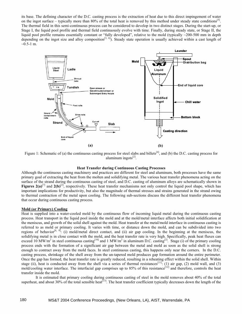
its base. The defining character of the D.C. casting process is the extraction of heat due to this direct impingement of water on the ingot surface – typically more than 80% of the total heat is removed by this method under steady state conditions[5]. The thermal field in this semi-continuous process can be considered to develop in two distinct stages. During the start-up, or Stage I, the liquid pool profile and thermal field continuously evolve with time. Finally, during steady state, or Stage II, the liquid pool profile remains essentially constant or “fully developed”, relative to the mold (typically ~200-500 mm in depth depending on the ingot size and alloy composition[3, 6]). Steady state operation is usually achieved within a cast length of ~0.5-1 m.
Mold
Liquid Aluminum
Chill water
Bottom block
Launder
Distribution bag
SolidifiedIngot
Casting direction
Spout
End of liquid core
Mold
Liquid Aluminum
Chill water
Bottom block
Launder
Distribution bag
SolidifiedIngot
Casting direction
Spout
End of liquid core
(b)
Slab
(a)
Figure 1: Schematic of (a) the continuous casting process for steel slabs and billets[4], and (b) the D.C. casting process for aluminum ingots[2].
Heat Transfer during Continuous Casting Processes
Although the continuous casting machinery and practices are different for steel and aluminum, both processes have the same primary goal of extracting the heat from the molten and solidifying metal. The various heat transfer phenomena acting on the surface of the strand during the continuous casting of steel, and D.C. casting of aluminum alloys are schematically shown in Figures 2(a)[7] and 2(b)[2], respectively. These heat transfer mechanisms not only control the liquid pool shape, which has important implications for productivity, but also the magnitude of thermal stresses and strains generated in the strand owing to thermal contraction of the metal upon cooling. The following sub-sections discuss the different heat transfer phenomena that occur during continuous casting process. Mold (or Primary) Cooling Heat is supplied into a water-cooled mold by the continuous flow of incoming liquid metal during the continuous casting process. Heat transport in the liquid pool inside the mold and at the mold/metal interface affects both initial solidification at the meniscus, and growth of the solid shell against the mold. Heat transfer at the metal/mold interface in continuous casting is referred to as mold or primary cooling. It varies with time, or distance down the mold, and can be subdivided into two regions of behavior[8, 9]: (i) mold/metal direct contact, and (ii) air gap cooling. In the beginning at the meniscus, the solidifying metal is in close contact with the mold, and the heat transfer rate is very high. Specifically, peak heat fluxes can exceed 10 MW/m2 in steel continuous casting[10] and 1 MW/m2 in aluminum D.C. casting[2]. Stage (i) of the primary cooling process ends with the formation of a significant air gap between the metal and mold as soon as the solid shell is strong enough to contract away from the mold faces. In steel continuous casting, this happens only near the corners. In the D.C. casting process, shrinkage of the shell away from the un-tapered mold produces gap formation around the entire perimeter. Once the gap has formed, the heat transfer rate is greatly reduced, resulting in a reheating effect within the solid shell. Within stage (ii), heat is conducted away from the shell via a series of thermal resistances[11]: (1) air gap, (2) mold wall, and (3) mold/cooling water interface. The interfacial gap comprises up to 85% of this resistance[12] and therefore, controls the heat transfer inside the mold.
It is estimated that primary cooling during continuous casting of steel in the mold removes about 40% of the total superheat, and about 30% of the total sensible heat[13]. The heat transfer coefficient typically decreases down the length of the
MS&T 2004 Conference Proceedings, (New Orleans, LA), AIST, Warrendale, PA180

mold from a peak value of 1500-2000 W/m2/K at the meniscus to about 600-800 W/m2/K[14] near the mold bottom. Many strand defects, such as transverse mid-face and corner cracks, can be directly attributed to factors that control primary heat transfer in the mold, including oscillation marks, improper mold lubrication, metal level fluctuations in the mold, and improper mold taper[15, 16]. Primary cooling in the mold accounts for only about 20% of the total heat extracted[17] from the solidifying ingot during the D.C. casting of aluminum alloys, but it still has a critical influence on the ingot surface microstructure and roughness[18]. The heat extracted by primary cooling determines the surface temperature of the ingot at the point of exit from the mold. This subsequently influences the mode of boiling water heat transfer (film/nucleate boiling) below the mold[19], as discussed later. The peak heat transfer coefficient reported for aluminum contacting a chilled mold ranges from 2000-4000 W/m2/K[20]. By comparison, in the air gap, the heat transfer coefficient may be as low as 150 W/m2/K [21]. Steel from
tundish
Water cooled copper mold
Steel strand
Water sprays
PRIMARYCOOLING
SECONDARYCOOLING
RADIATIVECOOLING
Water-cooled aluminum mold
Water curtain rolling down the vertical surfaces
Aluminum ingot
Bottom block
Aluminum from distributor bag
PRIMARYCOOLING
SECONDARYCOOLING
BAS E COOLING
(Predominantly during the start-
up phase)(a) (b)
Steel from tundish
Water cooled copper mold
Steel strand
Water sprays
PRIMARYCOOLING
SECONDARYCOOLING
RADIATIVECOOLING
Water-cooled aluminum mold
Water curtain rolling down the vertical surfaces
Aluminum ingot
Bottom block
Aluminum from distributor bag
PRIMARYCOOLING
SECONDARYCOOLING
BAS E COOLING
(Predominantly during the start-
up phase)(a) (b)
Figure 2: Schematic of cooling processes, for (a) continuous casting of steel[7] and (b) D.C. casting of aluminum[2].
An important factor controlling the extent of primary cooling is the effect of the cooling water on temperature and distortion of the mold itself. During the continuous casting of steel, cooling water flowing through the vertical slots in the copper mold extract heat from the mold and simultaneously control its temperature. The hot-face temperature of the mold indirectly affects the heat extraction rate, by altering the properties of the interfacial gap. Mold variables directly control mold temperature, but the effects on primary cooling are more complex. For example, decreasing the velocity of the cooling water lowers the heat transfer coefficient at the cold-face wall of the mold, causing mold temperature to increase[14]. Increasing the temperature of the hot-face wall of the mold may partially melt the slag rim, leading to increased heat extraction from the mold. The effect is counter-intuitive as primary cooling might increase with less cooling water. The impact of mold cooling water on primary cooling during the D.C. casting of aluminum has not been explored, perhaps because the mold cooling water also has an even more important role below the mold. Research has mostly focused on the secondary heat extraction process of direct impingement of water on the hot metal surface exiting the mold. Water (or Secondary) Cooling After emerging from the mold, the continuous-cast strand is cooled by direct contact of water with the hot metal surface, as shown in Figures 2(a) and 2(b). This is referred to as secondary cooling. For steel casting, banks of nozzles located between contact rolls beneath the mold, spray water to cool the moving metal strand. Usually, the spray nozzles are arranged into banks or cooling zones, assigned to the top and bottom surfaces of particular strand segments[22]. The water is forced under high pressure as droplets that form a mist, which continuously impact upon the metal surface. Therefore, secondary cooling between each pair of rolls involves several different heat transfer mechanisms operating in different sub-zones, which are illustrated in Figure 3(a)[23]. These are: (i) roll contact cooling, (ii) radiation and air convection from the bare strand surface just in the roll bite just above the spray region, (iii) cooling due to spray water impingement, and (iv) water convection cooling just below the spray region, where water runs down the strand and collects in the roll bite. Bulging of the steel shell caused by ferrostatic pressure can affect these heat transfer sub-zones, especially near the roll bite and if the support rolls are spaced too far apart[24].
MS&T 2004 Conference Proceedings, (New Orleans, LA), AIST, Warrendale, PA 181

Impingement zone
Streaming zone
Angle of impingement
Mold
Liquid Aluminum
Water jet
(b)(a)
Radiation & Air Convection
EntrainedWater
Spray Cooling
Film Convection
34
Roll Contact Cooling
1
2
3
4
1
12
SupportRoll
SprayWater
Steel Shell
SprayNozzle
Impingement zone
Streaming zone
Angle of impingement
Mold
Liquid Aluminum
Water jet
Impingement zone
Streaming zone
Angle of impingement
Mold
Liquid Aluminum
Water jet
(b)(a)
Radiation & Air Convection
EntrainedWater
Spray Cooling
Film Convection
34
Roll Contact Cooling
1
2
3
4
1
12
SupportRoll
SprayWater
Steel Shell
SprayNozzle
Radiation & Air Convection
EntrainedWater
Spray Cooling
Film Convection
34
Roll Contact Cooling
1
2
3
4
1
12
SupportRoll
SprayWater
Steel Shell
SprayNozzle
EntrainedWater
Spray Cooling
Film Convection
34
Roll Contact Cooling
1
2
3
4
1
12
SupportRoll
SprayWater
Steel Shell
SprayNozzle
Figure 3: Schematic of (a) different cooling zones between the support rolls and spray nozzles during the continuous casting of steel[23], and (b) secondary cooling regimes during D.C. casting of aluminum[2].
For aluminum casting, water jets emerge from holes located below the water-cooled mold and directly contact the
metal surface, as shown in Figure 3(b)[2]. These jets form a continuous film, which wets the vertical ingot surfaces and rolls downwards. Referring to Figure 3(b), two distinct sub-zones can be distinguished on the ingot surface: (a) the water impingement zone, where abrupt cooling happens due to the direct contact with water, and (b) the streaming zone located below (a), where the heat flux diminishes as the water film loses momentum with increasing distance from the impingement point. The length of the water impingement zone is usually ~10-15 mm, depending on the diameter of water holes at the base of the mold and angle of impingement.
Secondary cooling mechanisms provided by water spray for steel and water film for aluminum have distinctly different characteristics[25], as presented in Figure 4(a) and 4(b). In spray cooling (Figure 4(a)), water droplets impinge onto the very hot steel surface and vaporize instantaneously to create a boundary layer, which prevents the water from wetting the surface. Heat extraction is higher towards the center of the impingement region, where more of the high-speed droplets have enough momentum to penetrate the vapor layer. Extremely irregular flow conditions develop within the vapor boundary layer and it eventually becomes wavy and is thinned out. The short contact times between the spray droplets and the strand surface increase with water velocity, owing to increased water momentum. Thus, the secondary cooling rate increases greatly with spray water flow rate, although it is almost independent of strand surface temperature. In contrast, under film cooling conditions (Figure 4(b)), water flows along the surface at a uniform velocity. As a result, the boundary layer of vapor between the water film and the metal surface tends to be thicker and unperturbed. However, as the metal surface cools, the vapor layer breaks down and the water film starts to contact the strand surface. The area of contact increases with decreasing strand surface temperature, and is accompanied by a sudden increase in heat transfer. The cooling process is transient and is difficult to control.
The extraction of heat by cooling water is quite complex for both water spray and film cooling conditions because it is governed by water boiling water phenomena[26], which depend greatly on temperature. As shown in Figure 5, four regions of heat transfer[26] can be clearly distinguished when cooling water comes in contact with a hot metal surface. In order of increasing surface temperature, they are: (i) Convective cooling at temperatures lower than 100°C, (ii) Nucleate boiling between 100°C and burnout temperature (500-700 oC for steel and ~ 200oC for aluminum), (iii) Transition boiling between burnout and the Leidenfrost temperature (700-1000oC for steel and 300-500oC for aluminum), and (iv) Film boiling at high temperatures (i.e. greater than Leidenfrost temperature). It is also important to note that two important points characterize the boiling curve in Figure 5. They are: (i) the burnout temperature, which indicates the maximum heat flux (and heat transfer coefficient), and determines the maximum ability of the water film to cool the metal surface by nucleate/transition boiling, and (ii) the Leidenfrost temperature, which indicates the change in heat transfer mode from transition to vapor film boiling. Due to the strong co-relationship between the heat transfer coefficient and the surface temperature, heat extraction rates by secondary cooling can change rapidly with time and location near the Leidenfrost temperature. High heat transfer rates associated with nucleate boiling can cause the surface temperature to decrease rapidly. In contrast, the low heat transfer rates associated with film boiling can allow the surface temperature to increase. As a result, abrupt changes in the metal surface temperature can occur as the boiling phenomena shift from nucleate to film boiling and vice versa, depending on whether the
MS&T 2004 Conference Proceedings, (New Orleans, LA), AIST, Warrendale, PA182

Leidenfrost temperature is exceeded or not. Also, extreme variations of cooling can occur simultaneously at different locations on the metal surface, depending upon the local boiling behavior.
Vapor boundary
layer
Contact area between water
and surface
Spray water
Vapor boundary
layer
Water film
Contact area increases
wi th time as the surface cools
(b)(a)
Vapor boundary
layer
Contact area between water
and surface
Spray water
Vapor boundary
layer
Water film
Vapor boundary
layer
Water film
Contact area increases
wi th time as the surface cools
(b)(a)
Figure 4: Details[25] of the water cooling process for (a) continuous casting of steel (by spray water), and (b) D.C. casting of
aluminum (by water film).
Burnout Temperature
FILM BOILING
TRANSITION BOILING
LeidenfrostTemperature
Boi
ling
Wat
er H
eat
Tra
nsfe
r C
oeff
icie
nt
Onset of steam bubble
nucleation
Onset of continuous
film of steam bubbles
MaximumHeat Flux
NUCLEATE BOILING
FORCED CONVECTION
Cast Metal Surface Temperature
Figure 5: Generic boiling curve for water-cooling indicating the different heat transfer regimes[26].
The various heat transfer mechanisms associated with secondary cooling during continuous casting of both steel and aluminum are important because they determine the temperature gradients that develop inside the solidifying strand. Thus, they significantly influence the development of internal thermal stress/strain below the mold, and can aggravate defects generated inside the mold or introduce new defects. Quality problems related to secondary cooling will be discussed in Section III. Radiative Cooling during Continuous Casting of Steel
Beyond the spray zone region, the heat transfer process simplifies to radiation and natural convection. The smaller cooling rate of radiative cooling results in reheating of the solidified strand, which causes the strand surface to expand. If the surface reheats too much before complete solidification, then plastic deformation of the hot austenitic shell and semi-solid core may not be able to accommodate this expansion. This may cause sub-surface hot-tear cracks to form at the solidification front[27]. These cracks can cause internal segregation defects, or they may propagate through to the surface during later processing, such as rolling. Ingot Base Cooling during the D.C. Casting of Aluminum Alloys Secondary cooling also plays an important role in cooling the ingot base during the beginning of the start-up phase of the D.C. casting process. As the liquid metal enters the bottom block, the initial rate of heat transfer from the molten metal to the cold bottom block is extremely high. After a very short time, a small gap at the interface forms due to solidification shrinkage and the rate of heat transfer drops. This gap remains relatively small until the ingot begins to withdraw from the mold and is subjected to the secondary cooling water. At this point the base experiences a large macroscopic thermal distortion, called “butt curl”. This is aggravated by the slow cooling of the base, owing to the large gap and lack of water, combined with high thermal contraction of the vertical sides of the ingot, which experience higher heat extraction from the direct contact of a stable curtain. As the base continues to deform (or curl), water flowing down the sides may enter the bottom gap (water incursion) and enhance the heat transfer from the ingot base[2]. This in turn will influence further deformation of the base.
MS&T 2004 Conference Proceedings, (New Orleans, LA), AIST, Warrendale, PA 183

Strand Cooling Behavior Figures 6(a)[23] and (b)[28] compare typical surface temperature profiles along the strand length observed during the continuous casting of steel and aluminum alloys, respectively. Figure 6(b) also compares two aluminum ingots, produced by D.C. casting at different cooling rates (lower water flow rates were used for the hot cast). The primary and secondary cooling heat transfer regimes can be easily identified in the cooling curves of both processes (refer to the cold cast in Figure 6(b)).
900
1000
1100
1200
1300
1400
1500
0 1000 2000 3000 4000 5000
Distance below meniscus (mm)
Shel
l Sur
face
Tem
pera
ture
(o C)
Roll contact cooling troughs
Spray cooling troughs
PrimaryCooling Regime Secondary Cooling Regime
Distance below meniscus (mm)
Tem
pera
ture
(°C
)
0 100 200 300 400
100
200
300
400
500
600
700
800
Cold CastHot Cast
MeniscusCooling
Air gapCooling
Secondary CoolingRegime
PrimaryCoolingRegime
Heat transfer byNucleate Boiling
Point of water impingement
Heat transfer byFilm Boiling
(b) (a)
Figure 6: Typical surface temperature profile and cooling regimes along strand length during continuous casting of (a) steel[23] and (b) aluminum[28].
For steel, the extent of primary cooling is important, as it results in a temperature drop of ~250 °C, whereas for
aluminum the initial drop in the mold is ~100 °C. This is followed by reheating caused by the long air gap. Below the mold, the temperature during the continuous casting of steel varies over ~100 °C over each roll pitch, as shown in Figure 6(a). Near the top of the caster, the greatest surface temperature drop occurs beneath each spray jet, while a tiny dip occurs at each small region of direct contact with a contact roll. Lower in the caster, the growing ferrostatic pressure increases the local heat extraction during roll contact, which makes the relative size of the spray and roll-contact dips become closer.
In contrast, during the D.C. casting process, Figure 6(b) shows that aggressive cooling from direct impingement of water at a high flow rate onto the metal surface causes the ingot surface to cool monotonically by ~450-500 °C in only 300mm. With less water, the hot cast did not achieve sufficient cooling at the impingement zone, allowing the surface temperature of the ingot to exceed the Leidenfrost temperature. As a result, the heat transfer was in the film boiling range (refer to Figure 5), such that the rate of heat transfer was low and kept the solidifying shell dangerously hot near the solidus temperature for a long time. This also caused the macro-deformation of the ingot base to decrease from ~50 mm for the cold cast to ~6 mm for the hot cast.
Quality Problems Related to Secondary Cooling One of the most important objectives of continuous casting is to attain a defect-free slab or ingot. Two such quality issues are: (i) hot tearing and cold cracking, and (ii) dimensional control (e.g. bulging of the steel shell and butt curl for aluminum ingots). These problems are directly attributed to tensile mechanical and thermal stresses/strains generated during the casting process. The variety of crack defects that affect continuous cast steel slabs and D.C. cast aluminum ingots are shown schematically in Figures 7(a)[29] and (b)[30] respectively. Mechanically generated tensile strains, such as caused by inadequate mold lubrication or bending/straightening of the strand, usually act in the longitudinal direction and cause transverse cracking. During the casting process, rapid cooling can result in steep temperature gradients in the solidifying shell that can generate thermal strains as the shell expands and contracts. Sudden localized cooling can introduce tensile strains at the surface, whereas reheating can generate tensile strains at the solidification front. Thermals strains act predominantly in the transverse direction and are responsible for causing longitudinal cracks. Cracks can form if the generated tensile strain locally exceeds the strain-to-fracture of the metal. In steel, different regions of low ductility have been reported[29]. The most important one lies within ~50 °C of the solidus temperature, and is responsible for “hot tear” cracks. Aluminum experiences a similar rapid loss in strength and ductility between the solidus temperature and the tensile coherency point (i.e. the temperature corresponding to about 90% solid fraction)[31]. Other mechanisms involving sulfide, oxide, and nitride precipitates at the grain boundaries operate in steel at lower temperatures, between ~700 and 900 °C[15], and cause intergranular cold cracks.
Most cracks in steel slabs and billets are hot tears, due to the zone of low ductility near to the liquid front. Internal cracks are often seen near the corners, at the centerline or diagonally between opposite corners. Surface cracks can appear
MS&T 2004 Conference Proceedings, (New Orleans, LA), AIST, Warrendale, PA184

near both the midface or corner regions. Some cracks form below 900 °C during the straightening of the shell have been attributed to the embrittlement caused by precipitation of AlN near the grain boundaries[32]. In aluminum ingots/billets, hot tears or “pre-solidification” cracks can also form near the solidification front, when a tensile stress is imposed across partially solidified grains, and the surrounding liquid cannot fill the gap between the grains. Hence, these cracks are always inter-granular. In contrast, cold cracks in aluminum ingots are initiated at temperatures below the solidus due to extremely high thermal stresses, and are always trans-granular.
rface
ans
ansng ng arr
Su Cracks (initiated in the mold)
Tr verse cornerTr verse surfaceLo itudinal midfaceLo itudinal cornerSt
Off corner
Internal cracks (initiated at solidification front)
Midway StraighteningPinch roll
Radial streaks
Centerline Triple pointDiagonal
Surface Cracks (initiated in the mold)
Transverse cornerTransverse surfaceLongitudinal midfaceLongitudinal cornerSta
Off corner
Internal cracks (initiated at solidification front)
Midway StraighteningPinch roll
Radial streaks
Centerline Triple pointDiagonal
Center CrackJ Crack
Quarter-pointCrack
Rolling Face
NarrowFace
Casting direction
Center CrackJ Crack
Quarter-pointCrack
Rolling Face
NarrowFace
Casting direction
(b)(a)
Figure 7: Schematic of crack defects related to (a) continuous casting of steel[29], and (b) D.C. casting of aluminum[30]. Brimacombe et al[7] have summarized the causes of cracking problems in continuous cast steel. Improper secondary
cooling practices contribute to many of these. Excessive spray cooling and/or insufficient spray length lead to surface reheating, which induces tensile stresses beneath the surface, including the solidification front. This can cause internal cracks such as midway cracks in billet casting. Unsymmetrical cooling at the billet corners induces distortion and diagonal cracks. Excessive spraying of water can lead to rapid cooling and large tensile strains at the surface of slab castings, which can open up small cracks formed in the mold. However, insufficient spray cooling below the mold can allow the slab to bulge out if the surface becomes too hot. This can lead to several defects, such as triple point cracks, midface cracks, midway cracks, centre-line cracks and centre segregation, as shown in Figure 7(a). Transverse surface and corner cracks begin in the mold, but can open up due to axial tensile stresses induced by spray cooling during slab casting, when the surface temperature is within the low-ductility range of 700-900°C. Secondary cooling practices that lead to excessive surface temperature fluctuations also aggravate these cracks, especially in this critical temperature range.
The thermal stresses and strains generated in the ingot during the transient start-up phase of D.C. casting process can initiate hot tears and cold cracks, especially in high strength aluminum alloys[33]. As shown in Figure 7(b), hot tears generally form between the quarter points of a rectangular ingot and may not be visible on the ingot surface. Cold cracks also originate at the ingot base and are usually located in the centre half of the ingot width. High casting speeds tend to cause hot tears and low casting speeds increase the risk of cold cracks[3]. The formation of hot tears has also been linked with the frictional forces between the ingot and mold (which is related to mold cleanliness)[34] and the variability in cooling conditions during the transient start-up phase[35]. In addition to cracks, thermal stresses related to secondary cooling also generate macro-deformation of the ingot base or butt curl especially during start-up. As reported by Droste and Schneider[36], production problems related to butt curl include: run outs of the melt, cold shuts, reduced rigid standing (instability) of the ingot on bottom block, and low recovery rates. Ultimately, if the magnitude of butt curl is excessive, the ingot bottom may have to be removed.
Fundamental Investigations of Water Cooling Processes Experiments have been conducted to quantify heat transfer from water cooling and to establish boiling water curves (refer to Figure 5) in controlled laboratory experiments on small steel[7, 37-42] and aluminum[43-51] samples, in plant measurements of secondary cooling in the continuous casting of steel[52], and in D.C. casting of aluminum[53-56]. Generally, empirical relationships are developed by applying inverse heat transfer analysis to the measurements recorded by thermocouples embedded in the plate or casting. Figure 8[7, 43] compares typical boiling curves for steel and aluminum alloys obtained from such laboratory studies. Although the basic features of the boiling curves for the two systems are the same, the magnitude of the maximum heat flux and Leidenfrost temperatures will differ due to the differences in thermo-physical properties[25] of the two metals as well as surface effects such as oxide layers and surface roughness.
MS&T 2004 Conference Proceedings, (New Orleans, LA), AIST, Warrendale, PA 185

0
1
2
3
4
5
6
0 200 400 600 800 1000 1200 1400 1600 1800 2000
Temperature (°C)
Boili
ng w
ater
hea
t flu
x ( M
W m
-2 )
SteelAluminum alloys
Typical operating conditions forcasting steel
Typical operating conditions for
casting aluminum
Start-up
Steady state
Figure 8: Typical boiling curves and operating temperature ranges in the secondary cooling regime for continuous casting of steel[7] and D.C. casting of aluminum[43].
Studies on secondary cooling and the boiling water curve for the continuous casting of steel reveal the following
observations: 1. Typical values of maximum heat transfer coefficient measured by different researchers[39, 40, 52] lie between 2.0-3.0
kW/m2/K at the burnout temperature of ~500-700 °C. 2. Within the desired surface temperature range of 900-1200 °C for spray cooling, the surface temperature of the strand
has little impact on the spray heat transfer coefficient. This relative lack of dependence clearly indicates that the heat transfer mechanism is dominated by the convective heat transport occurring between the surface of the casting and a stable film of steam adhering to it (film boiling).
3. Within the film boiling regime, the spray heat transfer coefficient has a strong correlation with the water flow rate, as represented by the following empirical relationship[41]:
[1] cspray WAh &=
where hspray is the spray heat transfer coefficient (in W/m2/K), A and c are fitting parameters, and W is the water flow rate (in l/m
&2/s). Typically, A is 0.45 to 0.75, and c is 0.5-1.0[7].
4. Increasing the discharge velocity of the spray droplets increases their momentum to break through the vapor layer, which suppresses stable film boiling, and thus increases the heat transfer rate[39].
5. The Leidenfrost temperature is ~1000 oC and increases sharply with increasing water flow rate, for the same reason. From the secondary cooling studies conducted for D.C. casting of aluminum alloys, the following observations can be
made: 1. There is a general agreement between different measurement techniques that the maximum heat flux is between 1-5
MW/m2, and the maximum heat transfer coefficient lies between 40 and 50 kW/m2/K. The corresponding burnout temperature is ~200-250 oC.
2. Fundamentally, the operating temperature range of 220-620 oC is wider than for steel casting, extending down to the burnout temperature, so the ingot surface temperature has more effect on the heat transfer.
3. The Leidenfrost temperature is ~250-350 oC and increases with increasing water flow rate, in the same way as observed for steel. The heat transfer coefficient at the Leidenfrost temperature is very sensitive to water flow rate at low flow rates. Thus, water flow rate determines whether stable film boiling or water ejection will occur during start-up of D.C. casting. The Leidenfrost temperature can also be influenced by the water quality as well as the water temperature[48].
4. The oblique orientation of the water nozzle used in D.C. casting greatly affects the heat transfer. Because flow is directed downward along the ingot surface, the heat flux varies greatly with distance above or below its maximum at the impingement point. It drops significantly in the region of back flow above the impingement point. It decreases only gradually with distance below the impingement point as the water film loses momentum, and can be ejected from the surface by the formation of a stable vapor barrier.
MS&T 2004 Conference Proceedings, (New Orleans, LA), AIST, Warrendale, PA186
5. The rate of heat extraction is a strong function of metal surface temperature[43]. The heat flux also depends strongly on the initial temperature of the surface when water is first added, which affects the transient co-evolution of the water layer and the metal surface temperature.
Model Applications The heat transfer relations obtained from experimental measurements described in the previous section allow the study of thermomechanical behavior in continuous casting processes using mathematical models. These relations can be implemented as Cauchy type boundary conditions into finite-difference (FD) or finite-element (FE) based computational models to describe the cooling processes. These models can then predict the evolution of temperature, shell thickness, stress, and strain in the strand as it is cooled first in the mold and then during the secondary cooling zones. Predicted results from some of these models are presented here to provide further insight into the heat transfer phenomena acting during the continuous casting of steel and aluminum.
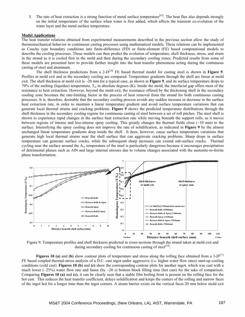
The shell thickness predictions from a 2-D[24] FE based thermal model for casting steel is shown in Figure 9. Profiles at mold exit and in the secondary cooling are compared. Temperature gradients through the shell are linear at mold exit. The shell thickness at mold exit is ~20 mm for a typical case, as shown in Figure 9, and its surface temperature drops to 70% of the melting (liquidus) temperature, Tm in absolute degrees (K). Inside the mold, the interfacial gap offers most of the resistance to heat extraction. However, beyond the mold exit, the resistance offered by the thickening shell in the secondary cooling zone becomes the rate-limiting factor in the process of heat removal from the strand for both continuous casting processes. It is, therefore, desirable that the secondary cooling process avoids any sudden increase or decrease in the surface heat extraction rate, in order to maintain a linear temperature gradient and avoid surface temperature variations that can generate local thermal strains and cracking problems. Figure 9 shows the predicted temperature distributions through the shell thickness in the secondary cooling regime for continuous casting of steel between a set of roll pitches. The steel shell is shown to experience rapid changes in the surface heat extraction rate while moving beneath the support rolls, as it moves between regions of intense and less-intense spray cooling. This greatly changes the thermal fields close (~10 mm) to the surface. Intensifying the spray cooling does not improve the rate of solidification, as indicated in Figure 9 by the almost unchanged linear temperature gradients deep inside the shell. It does, however, cause surface temperature variations that generate high local thermal strains near the shell surface that can aggravate cracking problems. Sharp drops in surface temperature can generate surface cracks, while the subsequent sharp increases can extend sub-surface cracks. Thermal cycling near the surface around the Ar3 temperature of the steel is particularly dangerous because it encourages precipitation of detrimental phases such as AlN and large internal stresses due to volume changes associated with the austenite-to-ferrite phase transformation.
0
0.1
0.2
0.3
0.4
0.5
0.6
0.7
0.8
0.9
1
0 10 20 30 40 50 60 70 80 90 100 110Distance beneath shell surface (mm)
Hom
olog
ous T
empe
ratu
re (T
/Tm
)
At Mold Exit (700mm below meniscus)Beneath Rolls (6980mm)
Between Rolls & Spray (7380mm)Beneath Spray (7420mm)Between Roll & Spray (7820mm)
Beneath Rolls (7860mm)
CenterSurface
Shell thickness at mold exit
Shell thickness at spray zone
0.5
0.55
0.6
0.65
0.7
0.75
0.8
0 1 2 3 4 5 6 7 8 9 10Distance beneath shell surface(mm)
Hom
olog
ous T
empe
ratu
re (T
/Tm
)
Beneath Rolls
Between Rolls & Spray
Beneath Spray
Between Roll & Spray
Beneath Rolls
Figure 9: Temperature profiles and shell thickness predicted in cross-sections through the strand taken at mold exit and during secondary cooling for continuous casting of steel[24].
Figures 10 (a) and (b) show contour plots of temperature and stress along the rolling face obtained from a 3-D[57]
FE based coupled thermal-stress analysis of a D.C. cast ingot under aggressive (i.e. higher water flow rates) start-up cooling conditions (cold cast). Figures 10 (b) and (c) show the corresponding contour plots for another ingot, which was cast with a much lower (~25%) water flow rate and faster (by ~20 s) bottom block filling time (hot cast) for the sake of comparison. Comparing Figures 10 (a) and (c), it can be clearly seen that a stable film boiling front is present on the rolling face for the hot cast. This reduces the heat transfer coefficient, delays solidification and keeps the centers of the rolling and narrow faces of the ingot hot for a longer time than the ingot corners. A steam barrier exists on the vertical faces 20 mm below mold exit
MS&T 2004 Conference Proceedings, (New Orleans, LA), AIST, Warrendale, PA 187

owing to the ejection of water film (accompanied by generation of steam) from those places where the temperature exceeds the Leidenfrost temperature. Figure 10 (a) also indicates that the base of the ingot near the centre of the rolling face is in the mushy state during the start-up phase. Referring to Figure 10 (b), it can be observed that this region is subject to tensile stress, in contrast to the region just above, where the material is cooler and in a state of compressive stress. This creates hot spots with high tensile strains just beneath the shell surface at the center of the vertical faces, which explains the initiation of hot tears that have been observed at this location[2]. Referring to Figure 10 (d), which contains the results from the hot cast, compressive stresses exist higher up on the ingot face in the region of the casting where the ejection front has begun to collapse. Lower down, within the ejection region, the material is in a state of moderate to low tension. Comparing the time history of plastic strain generation at Location “A” in Figures 10 (b) and (d), as shown in Figure 10 (e), the hot cast has substantially reduced plastic strain. This suggests less tendency for the accumulation of damage in the centre of the casting near the lip where hot cracks are often observed. These observations underline the necessity for optimal design of the secondary cooling processes during the continuous casting of both steel and aluminum alloys, in order to avoid the initiation and propagation of crack defects.
TT660.0607.1554.2448.3395.4342.5289.6236.7183.8130.877.925.0
emperature, T (°C)
S
M(a)
+251.6+214.5+177.5+140.4+103.3+66.2+29.2-7.9-44.9-82.0-119.1-156.2-193.2
Stress, (MPa)
C
T(b)
A
660.0607.1554.2448.3395.4342.5289.6236.7183.8130.877.925.0
emperature, T (°C)
S
M(a)
+251.6+214.5+177.5+140.4+103.3+66.2+29.2-7.9-44.9-82.0-119.1-156.2-193.2
Stress, (MPa)
C
T(b)
A
660.0607.1554.2448.3395.4342.5289.6236.7183.8130.877.925.0
Temperature, T (°C)
(c)
S
SM
M
Stress, (MPa)+216.1+182.1+148.2+114.4+80.5+46.6+12.7-21.2-55.1-88.9-122.9-156.8-190.7
(d)
CC
T
A
660.0607.1554.2448.3395.4342.5289.6236.7183.8130.877.925.0
Temperature, T (°C)
(c)
S
SM
M
Stress, (MPa)+216.1+182.1+148.2+114.4+80.5+46.6+12.7-21.2-55.1-88.9-122.9-156.8-190.7
(d)
CC
T
A
-0.005
0
0.005
0.01
0.015
0.02
0 100 200 300 400 500Time (s)
Plas
tic st
rain
(-)
Cold CastHot Cast
(e)
Figure 10: Contour plots of temperature and stress along the rolling face for D.C. cast ingots cast under two extreme cooling conditions – (a) & (b) for a cold cast), and (c) & (d) for a hot cast (refer to Figure 6b), and (e) comparison between plastic
strain evolutions for the two castings at Location A[57]. Legend: S: Solid, M: Mushy, C: Compression, and T: Tension
MS&T 2004 Conference Proceedings, (New Orleans, LA), AIST, Warrendale, PA188

Optimization of Water Cooling From the previous discussion, it is evident that water cooling plays a critical role during the continuous casting of steel and the start-up phase of the D.C. casting process for aluminum alloys. Hence, optimizing the parameters that control the cooling process is necessary to generate defect free castings. The task of optimizing secondary cooling is easier for steel continuous casting than for D.C. casting, because cooling is governed by film boiling phenomena so the heat transfer coefficient is relatively independent of the strand surface temperature. Relationships describing the variation of heat flux with nozzle type, nozzle-to-nozzle spacing, spray water flow rate, and distance of the spray nozzles from the strand surface are given in the literature[7, 39, 52, 58]. Under steady state conditions, spray practices can be designed to achieve cooling conditions that prevent defects. Specific techniques include “plateau cooling”[42] and air-water mist cooling[59]. The purpose of plateau cooling is to keep the surface temperature of the strand in the spray cooling zone always above 700°C, and to avoid reheating from below this temperature. This procedure can prevent cracks which are associated with the loss of ductility in steel at temperatures between 700-900°C. Air-water mist cooling has helped to provide more uniform cooling in both the casting and transverse directions, and hence avoids cracks by minimizing the localized temperature fluctuations caused by the undercooling and overcooling associated with water droplet spray jets. Furthermore, automatic control systems are available in the industry[22,
60] to adjust the sprays according to changes in casting speed and thereby optimize secondary cooling conditions for transient conditions as well. These control systems make use of online computational models to ensure that each portion of the shell experiences the same cooling conditions.
Unfortunately, in the case of D.C. casting, relatively little fundamental work has been done to optimize water-cooling phenomena to control the final ingot quality. Despite increased use of automation, the control of cooling conditions during start-up is difficult due to the many complex parameters and their interrelated effects on ingot cooling. A significant part of the problem to develop a fundamental approach to optimize the transient start-up phase is that the mold, the chill water, and the bottom block simultaneously cool the ingot surfaces. The combined interplay of primary and base cooling conditions determine the surface temperature of the ingot emerging from the mold, which in turn governs the boiling water-cooling conditions (film/nucleate boiling) that dictate the secondary cooling phenomena. The trend in the aluminum industry has been to control heat transfer by varying the bottom block filling rate, casting speed, and water flow rates during the start-up phase. Because the evolution of butt curl is directly linked with the amount of thermal stress generated in the ingot, attempts have been made in the industry to minimize the amount of curl by reducing the intensity of cooling during the start-up phase. It has further been suggested that combining low cooling water volume with high casting velocities during startup can reduce base deformation for some alloys[36]. If carried too far, however, these practices can cause extremely high local surface temperatures that can lead to extreme butt shrinkage and dangerous casting situations. Butt curl can also be reduced by solidifying a thick bottom shell, which bends to a lesser extent upon direct impingement of water. This can be achieved by appropriate bottom block design[61] or by using longer filling times[62]. Additional state-of-the-art water cooling systems include Alcoa’s CO2 injection[63], Wagstaff’s Turbo process[64], and Alcan’s Pulse Water technique[65]. Both the Alcoa and Wagstaff techniques use gases to promote film boiling. The gas bubbles in the water film quickly adhere to the ingot surface, generating an insulating layer that reduces the heat transfer coefficient. The Alcan process applies rotary valves to turn the cooling water on and off during the start-up phase. Thus, the average heat flux is lowered and the surface temperature of the ingot becomes high enough to trigger film boiling.
Over the past several decades, mathematical modeling has also been extensively used in the steel industry to control both the primary and secondary cooling processes. Models such as CASIM, DYNCOOL, and DYSCOS have been adopted by the industry for online process control[22]. The Continuous Casting Consortium at the University of Illinois at Urbana-Champaign have developed CON1D[23] and CON2D[66] programs to study the fundamentals of the complex but industrially-relevant phenomena in the mold and spray cooling regimes. Several industries and universities have formed consortiums to develop thermomechanical modeling tools to design and optimize the D.C. casting process using finite-element packages such as MARC[67], ABAQUS[67], and ALSIM/ALSPEN[17]. National laboratories in the United States have also collaborated recently to develop mathematical models to study ingot stress crack formation and butt deformation[68], and to reduce aluminum ingot scrap. In Canada, the University of British Columbia and Alcan International Ltd. are also jointly pursuing modeling activities to generate hot tearing criteria for the D.C. casting process[2, 57].
Summary and Conclusions
Although continuous casting processes for steel and aluminum alloys have different process design and operating parameters, the basic heat transfer processes characterizing the removal of superheat, latent heat and sensible heat are similar. Both the mold and water play significant roles in dictating the complex cooling phenomena under both transient and steady state conditions.
This paper shows how water-cooling governs the temperature of the metal strand, and how unsymmetrical or localized cooling problems can cause defects leading to high rejection rates and low productivity. The reader is referred to a forthcoming reference[69] for additional details. Specific observations include: (i) Empirical relations to describe cooling in the water channels are well established and used to optimize primary cooling in the mold during the continuous casting of steel. Perhaps the optimization of mold water cooling, which has been applied so successfully in the steel industry, could also help to improve the D.C. casting mold for aluminum.
MS&T 2004 Conference Proceedings, (New Orleans, LA), AIST, Warrendale, PA 189

(ii) In the case of continuous casting of steel, vapor film boiling dominates the heat extraction mechanism during spray cooling. As a result, the boiling water heat transfer coefficient is independent of strand surface temperature, and heat extraction is controlled by water flow rate. In contrast, transition/nucleate boiling often arises during D.C. casting to cause aggressive cooling of the ingot surfaces. However, film boiling is desired during the transient cast start-up phase to reduce the effect of butt curl. Effects like water ejection and water incursion coupled with the rapidly changing ingot surface temperature during the transient phase can significantly complicate the heat transfer process. As a result, the process is extremely difficult to control. (iii) Empirical relationships describing the variation of boiling water heat transfer coefficient with spray nozzle type, nozzle separation, distance of the nozzle from the surface of the strand and water flow rate have been established for secondary cooling of steel. For D.C. casting of aluminum alloys, relationships describing boiling water heat transfer as a function of the water characteristics and interaction of the water with the surface of the material are not available. Only a few studies for certain specific aluminum alloys are available, which can describe the boiling water heat transfer during DC casting. (iv) Secondary cooling should be designed to cool the strand surface in a controlled, monotonic manner, in order to avoid severe temperature gradient fluctuations that cause cracks. Developments such as plateau cooling, air-mist cooling, and online process control with mathematical models has helped to improve secondary cooling in continuous casting of steel. A variety of processes have been developed for D.C. casting of aluminum. (v) Despite decades of plant trials and increased process automation, quality problems related to water cooling such as butt curl and hot tear cracks still nag the D.C. casting industry. Different proprietary “recipes” are currently used by different aluminum companies to change casting variables as a function of time and alloy during start-up. There is recent recognition of the need for well-validated, fundamentally based thermo-mechanical mathematical models of the D.C. casting process to aid further improvements, including the optimization of water-cooling practices.
Acknowledgements The authors wish to thank Natural Sciences and Engineering Research Council (NSERC), Canada for providing financial support for J. Sengupta and the Continuous Casting Consortium at the University of Illinois at Urbana-Champaign.
References 1. C. Li and B.G. Thomas, "Analysis of the Potential Productivity of Continuous Cast Molds", Proceedings of the
Brimacombe Memorial Symposium, Vancouver, Canada, The Minerals, Metals and Materials Society, Warrendale, USA, 17, 2000.
2. J. Sengupta et al., "On the development of a 3-D transient thermal model to predict ingot cooling behaviour during the start-up phase of Direct Chill casting process for an AA5182 aluminum alloy ingot", Metallurgical & Materials Transactions B, 35B, 523-540, 2004.
3. J.F. Grandfield and P.T. McGlade, "D.C. Casting of Aluminum: Process Behaviour and Technology", Materials Forum, 20, 29-51, 1996.
4. B.G. Thomas, in The Encyclopedia of Materials: Science and Technology, Volume II, Ed. D. Apelian, Elsevier Science Ltd., Oxford, UK, 2000.
5. E.K. Jensen, "Mathematical Model Calculations in Level Pour D.C. Casting of Aluminum Extrusion Ingots", Light Metals 1980, The Minerals, Metals and Materials Society, Warrendale, USA, 631-642, 1980.
6. W.K.J. Jones et al., "Effects of Combo Bag Geometry on the Thermal History and Sump Profile of a 3104 D.C. Cast Ingot", Light Metals 1999, The Minerals, Metals & Materials Society, Warrendale, USA, 841-845, 1999.
7. J.K. Brimacombe et al., in Continuous Casting Vol. II: Heat Flow, Solidification and Crack Formation, Ed. J.K. Brimacombe, I.V. Samarasekera, and J.E. Lait, The Iron and Steel Society of AIME, USA, 109-123, 1984.
8. M. Trovant and S. Argyropoulos, "A Technique for the Estimation of Instanteneous Heat Transfer at the Mould/Metal Interface during Casting", Light Metals 1997 (Ed. R. Huglen), The Minerals, Metals and Materials Society, Warrendale, USA, 927-931, 1997.
9. Y. Meng and B.G. Thomas, "Modeling Transient Slag Layer Phenomena in the Shell/Mold Gap in Continuous Casting of Steel", Metallurgical Transactions B, 34B, 707-725, 2003.
10. J. Birat et al., "The Continuous Casting Mold: A Basic Tool for Surface Quality and Strand Productivity", Mold Operation for Quality and Productivity (Edited by A.W. Cramb and E. Szekeres), ISS, Warrendale, USA, 3-14, 1991.
11. B.G. Thomas et al., "Effect of Transverse Depressions and Oscillation Marks on Heat Transfer in the Continuous Casting Mold", in Sensors and Modeling in Materials Processing: Techniques and Applications, 1997, Orlando, Florida, The Minerals, Metals and Materials Society, USA.
12. I.V. Samarasekera and J.K. Brimacombe, "The Thermal Field in Continuous Casting Moulds", Canadian Metallurgical Quarterly, 18, 251-266, 1979.
13. X. Huang et al., "Modeling Superheat Removal during Continuous Casting of Steel Slabs", Metallurgical Transactions B, 23B, 339-356, 1992.
MS&T 2004 Conference Proceedings, (New Orleans, LA), AIST, Warrendale, PA190

14. R.B. Mahapatra et al., "Mold Behavior and its Influence on Product Quality in Continuous Casting of Slabs: Part II. Mold Heat Transfer, Mold Flux Behavior, Formation of Oscillation Marks, Longitudinal Off Corner Depressions, and Sub-surface Cracks", Metallurgical Transactions B, 22B, 875-888, 1991.
15. J.K. Brimacombe and K. Sorimachi, "Crack Formation in the Continuous Casting of Steel", Metallurgical Transactions B, 8B, 489-505, 1977.
16. J.K. Brimacombe et al., "Formation of Longitudinal, Midface Cracks in Continuously Cast Slabs", Metallurgical Transactions B, 10B, 279-292, 1979.
17. J.M. Drezet et al., "Thermomechanical Effects in D.C. Casting of Aluminum Alloy: A Numerical Benchmark Study", Materials Science Forum 2000, 329-330, 493-500, 2000.
18. W. Schneider and W. Reif, "Present Situation of Continuous Casting for Aluminum Wrought Alloys", in Proceedings of Symposium on Advances in Continuous Casting and Research Technology, 1992, Cairo, Egypt, Abington Publishing, UK.
19. D.C. Weckman and P. Niessen, "A Numerical Simulation of the D.C. Continuous Casting Process including Nucleate Boiling Heat Transfer", Metallurgical Transactions B, 13B, 593-602, 1982.
20. K. Ho and R.D. Pehlke, "Metal-Mold Interfacial Heat Transfer", Metallurgical Transactions B, 16B, 585-594, 1985. 21. Y. Nishida et al., "The Air-gap Formation Process at the Casting-Mold Interface and the Heat Transfer Mechanism
through the Gap", Metallurgical Transactions B, 17B, 833-844, 1986. 22. R.A. Hardin et al., "A Transient Simulation and Dynamic Spray Cooling Control Model for Continuous Steel
Casting", Metallurgical Transactions B, 34B, 297-306, 2003. 23. Y. Meng and B.G. Thomas, "Heat Transfer and Solidification Model of Continuous Slab Casting: CON1D",
Metallurgical Transactions B, 34B, 685-705, 2003. 24. L. Yu, "FEM Analysis of Bulging between Rolls in Continuous Casting", (Ph.D. thesis, Department of Mechanical
and Industrial Engineering, University of Illinois, Urbana-Champaign, USA, 1996). 25. H.M. Tansi and G.E. Totten, "Water Spray and Water Film Cooling", in Proceedings of the 3rd International
Conference on Quenching and Control of Distortion, 1999, Prague, Czech Republic. 26. F.M. White, Heat and Mass Transfer, A-W Publishing Company, 1991). 27. J.K. Brimacombe et al., in Continuous Casting Vol. II: Heat Flow, Solidification and Crack Formation, Ed. J.K.
Brimacombe, I.V. Samarasekera, and J.E. Lait, The Iron and Steel Society of AIME, USA, 1, 1984. 28. J. Sengupta et al., "The Effects of Water Ejection and Water Incursion on the Evolution of Thermal Field during
Start-up Phase of the D.C. Casting Process", Journal of Light Metals, 2(3), 137-148, 2002. 29. B.G. Thomas et al., "The Formation of Panel Cracks in Steel Ingots: A State of the Art Review, Part I - Hot
Ductility of Steel", Transactions of the Iron and Steel Society, 7, 7-20, 1986. 30. J. Du et al., "Computational Modeling of D.C. Casting of Aluminum Alloy Using Finite Element Method", Light
Metals 1998 (Ed. B. Welch), The Minerals, Metals & Materials Society, Warrendale, USA, 1025-1029, 1998. 31. L.J. Colley, "Measurement of Semi-solid Mechanical Property for Aluminum Alloy AA5182", (M.A.Sc. thesis,
Department of Metals and Materials Engineering, University of British Columbia, Vancouver, Canada, 2003). 32. J.K. Brimacombe, in Continous Casting Vol. II: Heat Flow, Solidification and Crack Formation, Ed. J.K.
Brimacombe, I.V. Samarasekera, and J.E. Lait, Iron and Steel Society of AIME, USA, 199-214, 1984. 33. J.E. Jacoby, "Direct Chill Casting Defects", in 5th Australasian Asian Pacific Conference on Aluminum Cast House
Technology, 1997, The Minerals, Metals and Materials Society. 34. A.A. Nofal, "Surface Defect Formation in the D.C.-cast Aluminum Products, Advances in Continuous Casting:
Research and Technology", in Proceedings of Symposium on Advances in Continuous Casting and Research Technology, 1992, Cairo, Egypt, Abington Publishing, UK.
35. J.B. Wiskel and S.L. Cockcroft, "Heat-flow-based Analysis of Surface Crack Formation during the Start-up of the Direct Chill Casting Process: Part II. Experimental Study of an AA5182 Rolling Ingot", Metallurgical Transactions B, 27B, 129-137, 1996.
36. W. Droste and W. Schneider, "Laboratory Investigations about the Influence of Starting Conditions on Butt Curl and Swell of D.C. Cast Sheet Ingots", Light Metals 1991 (Ed. E.L. Rooy), The Minerals, Metals & Materials Society, Warrendale, USA, 945-951, 1991.
37. M. Mitsutsuka, "Study on the Water Spray Cooling of Steel Plate at High Temperature", Tetsu-to-Hagane, 54, 1457-1471, 1968.
38. M. Shimada and M. Mitsutsuka, "On Heat Transfer Coefficients by Forced Water Cooling to Carbon Steel", Tetsu-to-Hagane, 52, 1643, 1966.
39. E. Mizikar, "Spray Cooling Investigation for Continuous Casting of Billets and Blooms", Iron Steel Engineer, 47, 53-60, 1970.
40. R. Alberny, Ed. Committee of European Communities, Luxembourg, IPC Science and Technology Press, 278-335, 1977.
41. T. Nozaki et al., "A Secondary Cooling Pattern for Preventing Surface Cracks, for Continuous Casting Slabs", Trans ISIJ, 18, 330-338, 1978.
MS&T 2004 Conference Proceedings, (New Orleans, LA), AIST, Warrendale, PA 191

42. E. Bolle and J.C. Moureau, "Experimental Study of Heat Transfer by Spray Cooling", in Int. Conf. on Heat and Mass Transfer Metallurgical Processes, 1979, Yugoslavia.
43. M.A. Wells et al., "Influence of Surface Morphology, Water Flow Rate, and Sample Thermal History on the Boiling-Water Heat Transfer during Direct-Chill Casting of Commercial Aluminum Alloys", Metallurgical Transactions B, 32B, 929-939, 2000.
44. A. Larouche et al., "Impact of Water Heat Extraction and Casting Conditions on Ingot Thermal Response during D.C. Casting", Light Metals 1998 (Ed. B. Welch), The Minerals, Metals and Materials Society, Warrendale, USA, 1059-1064, 1998.
45. H. Kraushaar et al., "Correlation of Surface Temperatures and Heat Transfer by D.C. Casting of Aluminum Ingots", Light Metals 1995 (Ed. J. Evans), The Minerals, Metals and Materials Society, Warrendale, USA, 1055-1059, 1995.
46. J. Langlais et al., "Measuring the Heat Extraction Capacity of D.C. Casting Cooling Water", Light Metals 1995 (Ed. J. Evans), The Minerals, Metals and Materials Society, Warrendale, USA, 979-986, 1995.
47. L. Maenner et al., "A Comprehensive Approach to Water Cooling in D.C. Casting", Light Metals 1997 (Ed. R. Huglen), The Minerals, Metals and Materials Society, Warrendale, USA, 701-707, 1997.
48. A. Larouche et al., "An Integrated Approach to Measuring D.C. Casting Water Quenching Ability", Light Metals 1999 (Ed. M. Bouchard and A. Faucher), MetSoc, Warrendale, USA, 235-245, 1999.
49. I.J. Opstelten and J. M.Rabenberg, "Determination of the Thermal Boundary Conditions during Aluminum D.C. Casting from Experimental Data using Inverse Modeling", Light Metals 1999 (Ed. C. E. Eckert), The Minerals, Metals and Materials Society, Warrendale, USA, 729-735, 1999.
50. J. Zuidema et al., "Secondary Cooling in DC Casting: Modeling and Experimental Results", Light Metals 2001 (Ed. J. L. Anjier), The Minerals, Metals and Materials Society, Warrendale, USA, 873-878, 2001.
51. L.I. Kiss et al., "Experimental Study of the Heat Transfer along the Surface of a Water-film Cooled Ingot", Light Metals 2002 (Ed. W. Schneider), The Minerals, Metals and Materials Society, 981-985, 2002.
52. S.G. Hibbins, in Continuous Casting Vol. II: Heat Flow, Solidification and Crack Formation, Ed. J.K. Brimacombe, I.V. Samarasekera, and J.E. Lait, The Iron and Steel Society of AIME, USA, 139-151, 1984.
53. J.B. Wiskel and S.L. Cockcroft, "Heat-flow-based Analysis of Surface Crack Formation during the Start-up of the Direct Chill Casting Process: Part I. Development of the Inverse Heat-Transfer Model", Metallurgical Transactions B, 27B, 119-127, 1996.
54. J.A. Bakken and T. Bergstrom, "Heat Transfer Measurements during D.C. Casting of Aluminum Part I: Measurement Technique", Light Metals 1986, The Minerals, Metals and Materials Society, Warrendale, USA, 883-889, 1986.
55. E.K. Jensen et al., "Heat Transfer Measurements during D.C. Casting of Aluminum Part II: Results and Verification for Extrusion Ingots", Light Metals 1986, The Minerals, Metals and Materials Society, Warrendale, USA, 891-896, 1986.
56. Y. Watanabe and N. Hayashi, "3-D Solidification Analysis of the Initial State of the D. C. Casting Process", Light Metals 1996 (Ed. W. Hale), The Minerals, Metals and Materials Society, Warrendale, USA, 979-984, 1996.
57. J. Sengupta et al., "Quantification of Temperature, Stress, and Strain Fields during the Start-up Phase of Direct Chill Casting Process by Using a 3-D Fully Coupled Thermal and Stress Model for AA5182 Ingots", Submitted to Metallurgical Transactions B in 2004.
58. L. Bendig et al., "Spray Parameters and Heat Transfer Coefficients of Spray Nozzles for Continuous Casting", in SteelMaking Conference Proceedings, 1995.
59. S.-M. Lee and S.-Y. Jang, "Problems in Using the Air-Mist Spray Cooling and its Solving Methods at Pohang No. 4 Continuous Casting Machine", ISIJ International (Japan), 36(Supplementary on Science and Technology of Steelmaking), 208-210, 1996.
60. L.A. Baptista, "Control of Spray Cooling in the Continuous Casting of Steel", (M.A.Sc. thesis, Department of Metals & Materials Engineering, University of British Columbia, Vancouver, Canada, 1979).
61. W. Schneider and E.K. Jensen, "Investigations about Starting Cracks in D.C. Casting of 6063-type Billets Part I: Experimental Results", Light Metals 1990 (Ed. C. M. Bickert), The Minerals, Metals and Materials Society, Warrendale, USA, 931-936, 1990.
62. W. Schneider, "D.C. Casting of Aluminum Alloys - Past, Present and Future", Light Metals 2002 (Ed. W. Schneider), The Minerals, Metals & Materials Society, Warrendale, USA., 953-960, 2002.
63. H. Yu, "A Process to Reduce D.C. Ingot Butt Curl and Swell", Light Metals 1980, The Minerals, Metals & Materials Society, Warrendale, USA, 613-628, 1980.
64. I. Wagstaff, U.S. Patent # 4,693,298, 1987. 65. N.B. Bryson, U.S. Patent # 3,411,079, Casting of Aluminum Ingots, 1969. 66. A. Moitra, "Thermo-mechanical Model of Steel Shell Behavior in Continuous Slab Casting", (Ph.D. thesis,
Mechanical & Industrial Engineering, University of Illinois, Urbana-Champaign, USA, 1993). 67. Trademark of MARC Analysis Research Corporation, Palo Alto, USA.
MS&T 2004 Conference Proceedings, (New Orleans, LA), AIST, Warrendale, PA192

68. Aluminum: Project Fact Sheet, Newsletter published by Office of Industrial Technologies, Energy Efficiency, and Renewable Energy, U. S. Department of Energy (DoE), Washington, D.C., 2000.
69. J. Sengupta et al., "The Use of Water Cooling during the Continuous Casting of Steel and Aluminum Alloys", submitted to Metallurgical Transactions A in 2004.
MS&T 2004 Conference Proceedings, (New Orleans, LA), AIST, Warrendale, PA 193