Understanding the ageing process in RPC’s from an ion conductivity approach.
18
Understanding the ageing process in RPC’s from an ion conductivity approach. C. Pecharromán 1 , M. Morales 2 , G. Mata-Osoro 1 , L. A. Díaz 3 , V. Valcárcel 4 , J. A. Garzón 2 1-Instituto de Ciencia de Materiales de Madrid (CSIC), Spain. 2-Centro de Investigación en Nanomateriales y Nanotecnología (CINN), (CSIC), Spain. 3-LabCaF, Facultad de Física, Universidad de Santiago de Compostela (USC), Spain. 4-Instituto de Cerámica de Galicia (ICG), Spain
-
Upload
jocelyn-cleveland -
Category
Documents
-
view
19 -
download
1
description
Understanding the ageing process in RPC’s from an ion conductivity approach. C. Pecharromán 1 , M. Morales 2 , G. Mata-Osoro 1 , L. A. Díaz 3 , V. Valcárcel 4 , J. A. Garzón 2 1-Instituto de Ciencia de Materiales de Madrid (CSIC), Spain. - PowerPoint PPT Presentation
Transcript of Understanding the ageing process in RPC’s from an ion conductivity approach.

Understanding the ageing process in RPC’s from an ion conductivity
approach.
C. Pecharromán1 , M. Morales2, G. Mata-Osoro1 , L. A. Díaz3 , V. Valcárcel4, J. A. Garzón2
1-Instituto de Ciencia de Materiales de Madrid (CSIC), Spain.
2-Centro de Investigación en Nanomateriales y Nanotecnología (CINN), (CSIC), Spain.
3-LabCaF, Facultad de Física, Universidad de Santiago de Compostela (USC), Spain.
4-Instituto de Cerámica de Galicia (ICG), Spain

Physical requirements for the resistive plate of a high rate
timing RPC (for instance CBM demands 20 kHz/cm2)
• Resistivity~ 109 m.
• Breakdown field Ev>>>1MVm-1 (1000V/mm)
• Thermal Stability.• Not a very high permittivity• I/V ohmic if possible (R field independent)• Easy to fabricate and not very expensive.

Conductivity of materials• Intrinsic materials are divided into insulator
and conductors.• Materials in the range of 10-9 -1m-1 are limited:
10-18
10-15
10-12
10-9
10-6
10-3
100
103
106
109
1012
Fu
sed
qu
arz
Tefl
on
Poly
eth
yle
ne
Am
ber
Para
ffin
Ru
bb
er
Su
lfu
rM
ica
Porcela
inS
tyro
foam
Ru
tile
(TiO
2)
Ru
tile
(TiO
2)(
Z)
Gla
ssM
arb
le Bak
eli
teD
isti
lled
wa
ter
Fu
sed
sil
ica
Beryll
ium
ox
ide(B
eO
)+In
trin
sic s
ilic
on
Sa
pp
hir
e+
Ferrit
e(F
e2O
3)+
Dry s
oil
Ple
xig
las+
Gall
ium
arse
nid
e (
GaA
s)+
Intr
insi
c g
erm
an
ium
Tell
uriu
mC
arb
on
Grap
hit
eC
ast
iron
Mercu
ry
Nic
hro
me
Sil
icid
es
Germ
an
sil
ver
Sil
icon
ste
el
Poly
sili
co
nL
ead
Tan
talu
mT
inP
lati
nu
mIr
on
Nic
kel
Zin
cT
un
gst
en
Brass
Alu
min
um
Gold
Cop
per
Sil
ver
Material
(S
)

Ceramic/Metal insulators• Physical Mixtures of substances with very different
conductivities.• The conductivity of these materials changes brusquely around
the percolation threshold.• Heterogeneities in composites with concentration close to the
percolation threshold spoil their properties.• Samples presented good homogeneity• Good conductivity values.• Samples can be machined.
0.0 0.1 0.2 0.3 0.4 0.5 0.6 0.7 0.8 0.9 1.010
-14
10-11
10-8
10-5
10-2
101
104
107
Con
cuct
ivity
-1m
-1)
f
fc
C. Pecharromán et al. Adv. Mater, 12, 294 (2000)

An example, Ni/BaTiO3 composites• Schottky and Tunneling conductivity behavior.
• Detected areas of very large electric fields (hot spots)• Samples suffer breakdown process at a certain Vc value.
0 100 200 300 400 500 600 700 800 900 1000-18
-16
-14
-12
-10
-8
-6
-4
-2
0
2
4
f=0.12 1300ºC 2h f=0.25 1300ºC 2h f=0.25 1350ºC 16h f=0.27 1300ºC 2hf=0.29 1300ºC 2h
Log(
J (A
m2 ))
E1/2 (V/m)1/2
1.0 1.2 1.4 1.6 1.8 2.0 2.2 2.4 2.6 2.8 3.0 3.210-12
10-11
10-10
10-9
10-8
10-7 T = 403 K T = 383 K T = 363 K T = 343 K T = 323 K
I (A
)
V1/2 (V1/2) 10-2 10-1101
102
103
104
105
= E
loc/E
(fc - f)
0 2x10⁵ 4x10⁵ 6x10⁵ 8x10⁵ 1x10610-12
10-11
10-10
10-9
10-8
10-7
10-6
10-5
10-4
12 Ni vol. % 25 Ni vol. % 27 Ni vol. % 29 Ni vol. %
(-1
·m-1)
E (V/m)
C. Pecharromán et al. Adv. Mater, 13, 1541 (2001)R. Jimenez et al., Ferroelectrics 268 807 (2002)C Pecharromán et. al. Ferroelectric (2010)

Conduction models for metal/insulator interfaces
P r o c e s s M a th . E x p r e s s .
T u n n e ll in g A W e Vj c te W e V e
F ie ld e m is s io n 326 .8 3
2W
Ej E e
Ele
ctro
de
pro
cess
es
S c h o ttk y 2sW E
k Tj A T e
O h m ic gW
k TE
j eT
Io n ic 2
dWW
k TE
j eT
P o o le F re n k e l d P FW E
k Tj E e
Insu
lato
r p
roce
sses
S p a c e C h a rg e 2
3
9
8
Vj
d
T independent
Log(I)~V1/2
I~V, Arrhenius
Log(I)~V1/2
electronic

Metal/ceramic composites under strong electric fields.
• Metallic phase is a good electronic field• Potential only drops in insulator regions.
Metal
Insulator
Metal
Insulator MetalMetal
Electron conductivity
ion conductivity

Mo/Mullite Composites• Why Mullite/Molybdenum?
• Mullite is an aluminum-silicate.– Its crystalline structure includes oxygen
vacancies– It has a very high dielectric strength– It has the same expansion coefficient as Mo
• Mo is a refractaire metal.• It is relatively stable against oxidation.• Processing of powders is quite simple.
MulliteHartmut Schneider (Editor), Sridhar Komarneni (Editor)

Mo/Mullite Composites• Electrical properties of Mu/Mo composites• I/V curves seem to indicate a space charge displacement
mechanism. (I~V2).• Conductivity is very sensitive to temperature.• I/T indicates a thermal activated mechanism.• An ion conduction mechanism, at high fields is proposed.
3.0 3.5 4.0 4.5 5.0 5.5 6.0 6.5 7.0-22
-20
-18
-16
-14
-12
-10
-8
-6
Mu/Mo 11 vol. %
log(
J) (
log(
Am
-2))
1000/T (K-1)
200 µm
0 1x10⁵ 2x10⁵ 3x10⁵ 4x1050.0
5.0x10⁻⁴
1.0x10⁻³
1.5x10⁻³
2.0x10⁻³
2.5x10⁻³
j (A
/m2 )
E (V/m)
11% 12% 13%
-1x10⁵ 0 1x10⁵ 2x10⁵ 3x10⁵ 4x1050
1x10⁻⁹
2x10⁻⁹
3x10⁻⁹
4x10⁻⁹
5x10⁻⁹
6x10⁻⁹
7x10⁻⁹
8x10⁻⁹
9x10⁻⁹
1x10⁻⁸
11 vol. Mo % 12 vol. Mo % 13 vol. Mo %
(
-1 m
-1)
E (V/m)
10 100 1000 10000 100000 10000000
5
10
15
20
25
30
Die
lect
ric
Con
stan
t
Frequency (Hz)
Mu/Mo 11 vol.% Glass
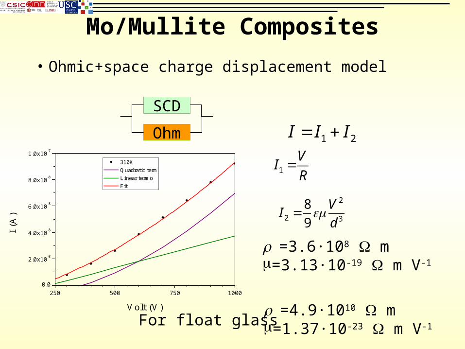
Mo/Mullite Composites
• Ohmic+space charge displacement model
250 500 750 10000.0
2.0x10⁻⁸
4.0x10⁻⁸
6.0x10⁻⁸
8.0x10⁻⁸
1.0x10⁻⁷
I (A
)
Volt (V)
310K Quadratic term Linear termo Fit
SCD
Ohm 1 2I I I
1
VI
R
2
2 3
8
9
VI
d
=3.6·108 m=3.13·10-19 m V-1
=4.9·1010 m=1.37·10-23 m V-1For float glass
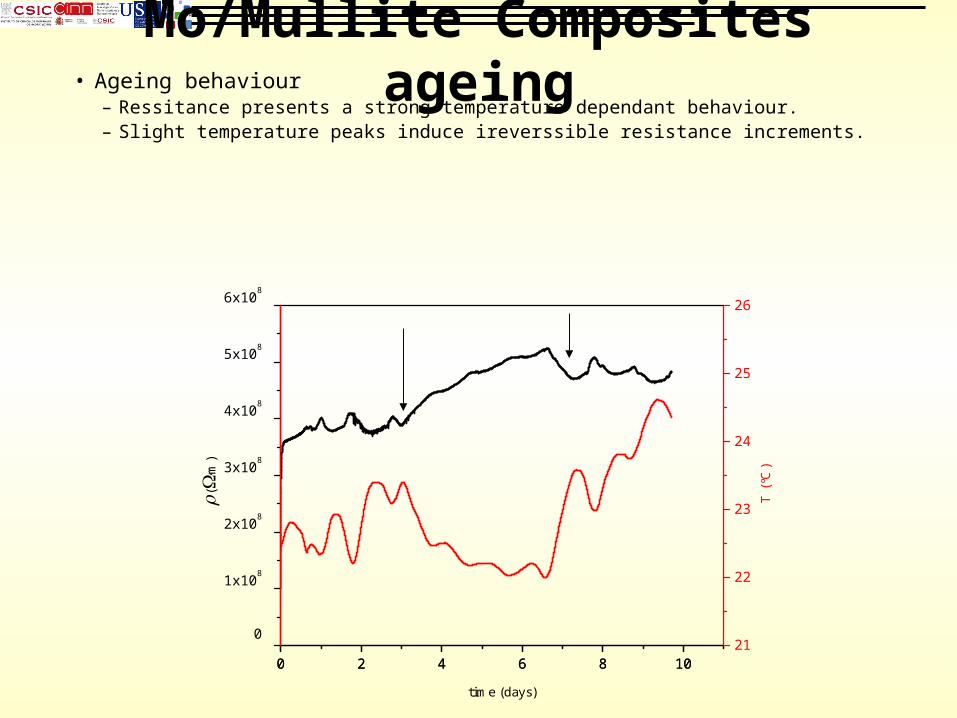
Mo/Mullite Composites ageing• Ageing behaviour
– Ressitance presents a strong temperature dependant behaviour.– Slight temperature peaks induce ireverssible resistance increments.
0 2 4 6 8 10
0
1x10⁸
2x10⁸
3x10⁸
4x10⁸
5x10⁸
6x10⁸
0 2 4 6 8 1021
22
23
24
25
26
(·
m)
T (
ºC)
time (days)
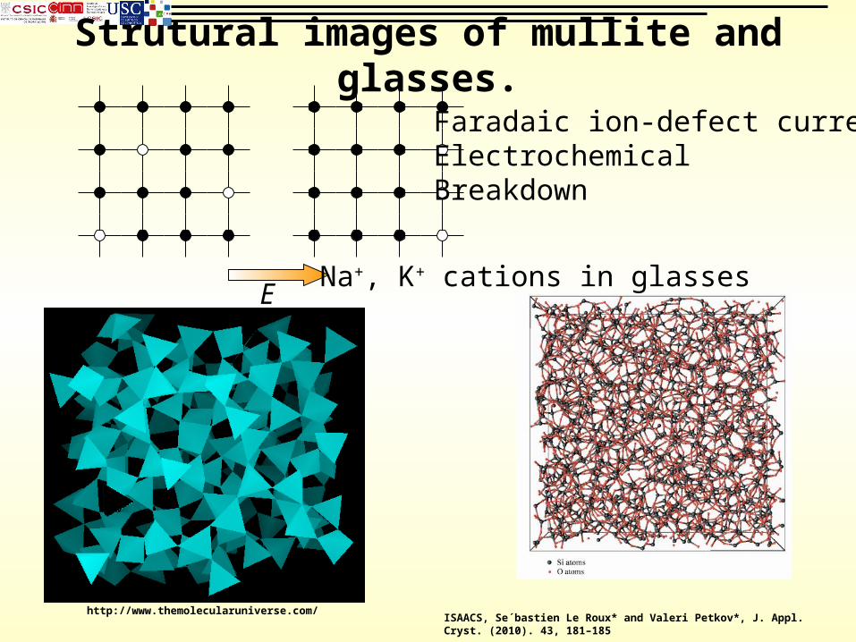
Strutural images of mullite and glasses.
http://www.themolecularuniverse.com/ISAACS, Se´bastien Le Roux* and Valeri Petkov*, J. Appl. Cryst. (2010). 43, 181–185
E
Faradaic ion-defect currentElectrochemical Breakdown
Na+, K+ cations in glasses

Simple model for composite electrochemical breakdown
• Time to induce a structural atomic failure by faradic current
• conductivity stops and atomic structure will collapse when a critical fraction of carriers abandon their equilibrium position . The fraction between total charge QT and charge defects Q is called (tolerance to faults in the crystalline structure).
•
• For crystals =10-5 ~ 10-17. Assuming =109 m and =10-11 then t is around some days
• For a glass with =10-11 -1m-1 may vary many orders of magnitude. An intermediate value is =10-12 which results t around of years
Qjdt Et
S
T
Q
Q
iT A
i i
qQ Vol N e
Mw 3810 equiv/gi i
i i
q f
Mw
1
T A T
Q E t
Q d N e
9 32 10
~A TN e C mt
V V

Glass ageing• Ageing behaviour– Resistance presents a strong temperature
dependant behavior.– Slight temperature peaks induce irreversible
resistance increments.– The damage degree is smaller than in the case
of Mu/Mo composites
0 24 48 72 960.0
5.0x10⁹
1.0x10¹⁰
1.5x10¹⁰
2.0x10¹⁰
2.5x10¹⁰
3.0x10¹⁰
3.5x10¹⁰
4.0x10¹⁰
(·
m)
time (h)
Equation y = a + b*x
Adj. R-Square 0.76774
Value Standard Error
Book1_E Intercept 3.15108E1 1.98784E7
Book1_E Slope 3.71745E7 410469.18948
20
24
28
T (
ºC)
0 2 4 6 8 10
0
1x10⁸
2x10⁸
3x10⁸
4x10⁸
5x10⁸
6x10⁸
0 2 4 6 8 1021
22
23
24
25
26
(·
m)
T (
ºC)
time (days)
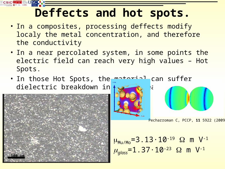
Deffects and hot spots.• In a composites, processing deffects modify localy
the metal concentration, and therefore the conductivity
• In a near percolated system, in some points the electric field can reach very high values – Hot Spots.
• In those Hot Spots, the material can suffer dielectric breakdown in these area.
100 µm
Pecharroman C, PCCP, 11 5922 (2009)
Mu/Mo=3.13·10-19 m V-1
glass=1.37·10-23 m V-1

New proposal.
• Mixtures formed by insulators and electron conductors (transition metal oxides) slightly above the percolation threshold.
0.0 0.1 0.2 0.3 0.4 0.5 0.6 0.7 0.8 0.9 1.0
10-14
10-11
10-8
10-5
10-2
101
104
107
Con
cuct
ivity
-1
m-1
)
f
fc
Metal/ceramic
Conductor Ceramic/Insulator ceramic
Electronic conduction from oxygen defects in transition metal oxides (Fe, Zn, Sn, Ni, Ti, etc).

Commercial ferrite behaviour
• Linear I/V response (Ohmic).• Conductivity does not vary so much
with T.• No ageing.• Too much conductivity (up to now)
1x10⁵ 2x10⁵ 3x10⁵ 4x10⁵ 5x10⁵ 6x10⁵ 7x10⁵ 8x1050.0
5.0x10⁻⁸
1.0x10⁻⁷
1.5x10⁻⁷
2.0x10⁻⁷
2.5x10⁻⁷
3.0x10⁻⁷
(
-1·m
-1)
E (V/m) 0 24 48 72 96 1200
1x10⁶
2x10⁶
3x10⁶
4x10⁶
5x10⁶
6x10⁶
7x10⁶
0 24 48 72 96 12030
31
32
33
34
35
36
(·
m)
Time (h)
Temperature
T
empe
ratu
re (
ºC)
Time (h)

Conclusions• Mu/Mo composites, with metal concentration
below fc presents good values for RPC materials, nearly ohmic behavior and high breakdown field.
• However, electrochemical ageing increases its resistance until breakdown happens after several days.
• Ion conduction must be avoided for long term operation. Only defective-tolerant atomic structures may work reasonably (float glass)
• Possible solution: transition metal oxide ceramics (Fe, Ni, Ti, Zn, Sn, Co, etc) with conductor phases slightly above the percolation threshold.