Understanding Injection Molds - Carl Hanser...
12
Sample Pages Harry Pruner, Wolfgang Nesch Understanding Injection Molds ISBN (Buch): 978-1-56990-527-2 ISBN (E-Book): 978-3-446-42877-5 For further information and order see http://www.hanser-fachbuch.de/978-1-56990-527-2 or contact your bookseller. © Carl Hanser Verlag, München
Transcript of Understanding Injection Molds - Carl Hanser...

Sample Pages
Harry Pruner, Wolfgang Nesch
Understanding Injection Molds
ISBN (Buch): 978-1-56990-527-2
ISBN (E-Book): 978-3-446-42877-5
For further information and order see
http://www.hanser-fachbuch.de/978-1-56990-527-2
or contact your bookseller.
© Carl Hanser Verlag, München
292.2 Molded Parts with Undercuts
2.2.2 Demolding through Sliders
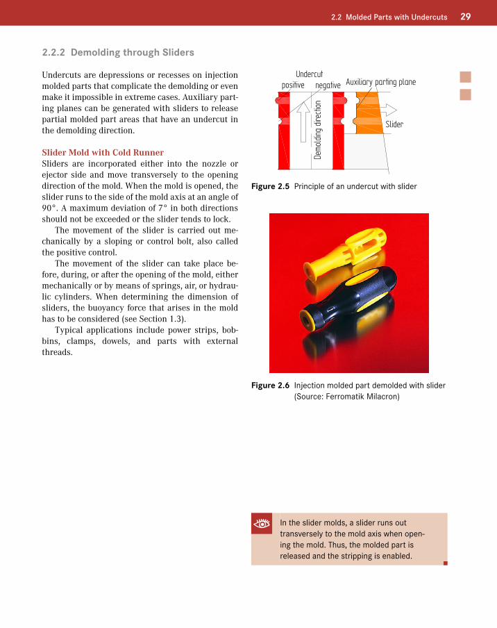
Undercuts are depressions or recesses on injection molded parts that complicate the demolding or even make it impossible in extreme cases. Auxiliary part-ing planes can be generated with sliders to release partial molded part areas that have an undercut in the demolding direction.
Slider Mold with Cold RunnerSliders are incorporated either into the nozzle or ejector side and move transversely to the opening direction of the mold. When the mold is opened, the slider runs to the side of the mold axis at an angle of 90°. A maximum deviation of 7° in both directions should not be exceeded or the slider tends to lock.
The movement of the slider is carried out me-chanically by a sloping or control bolt, also called the positive control.
The movement of the slider can take place be-fore, during, or after the opening of the mold, either mechanically or by means of springs, air, or hydrau-lic cylinders. When determining the dimension of sliders, the buoyancy force that arises in the mold has to be considered (see Section 1.3).
Typical applications include power strips, bob-bins, clamps, dowels, and parts with external threads.
Undercut positive negative Auxiliary parting plane
Slider
Demo
lding
dire
ction
Figure 2.5 Principle of an undercut with slider
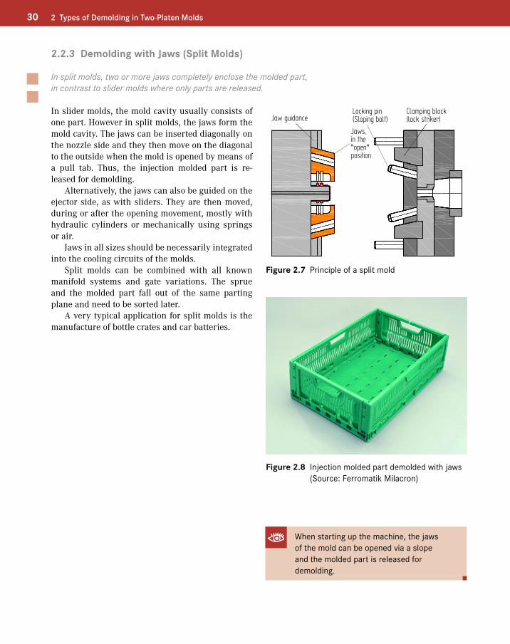
Figure 2.6 Injection molded part demolded with slider (Source: Ferromatik Milacron)
In the slider molds, a slider runs out transversely to the mold axis when open-ing the mold. Thus, the molded part is released and the stripping is enabled.
30 2 Types of Demolding in Two-Platen Molds
2.2.3 Demolding with Jaws (Split Molds)
In split molds, two or more jaws completely enclose the molded part, in contrast to slider molds where only parts are released.
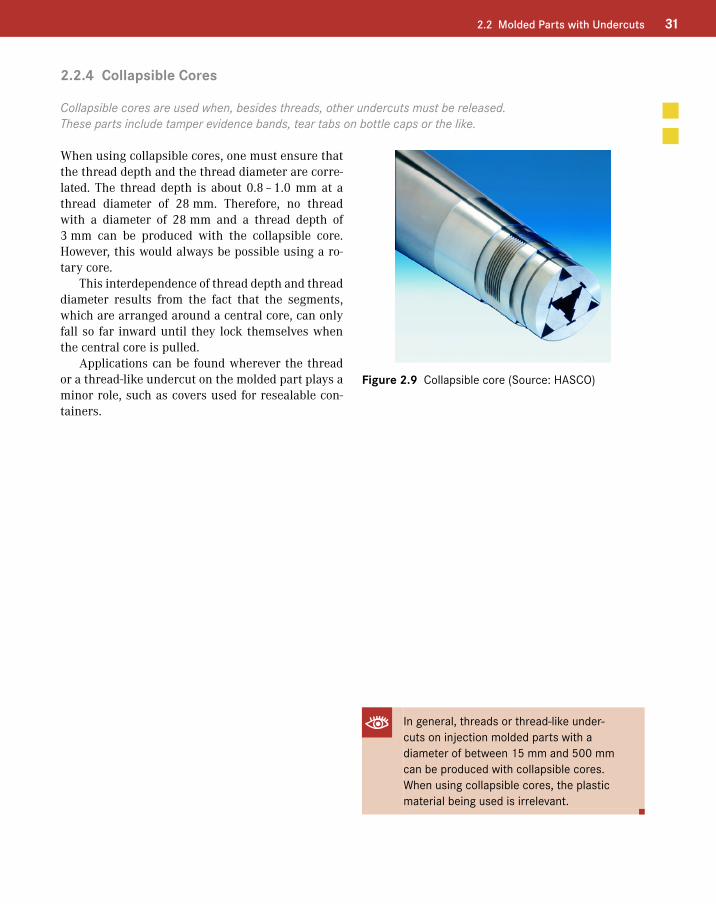
In slider molds, the mold cavity usually consists of one part. However in split molds, the jaws form the mold cavity. The jaws can be inserted diagonally on the nozzle side and they then move on the diagonal to the outside when the mold is opened by means of a pull tab. Thus, the injection molded part is re-leased for demolding.
Alternatively, the jaws can also be guided on the ejector side, as with sliders. They are then moved, during or after the opening movement, mostly with hydraulic cylinders or mechanically using springs or air.
Jaws in all sizes should be necessarily integrated into the cooling circuits of the molds.
Split molds can be combined with all known manifold systems and gate variations. The sprue and the molded part fall out of the same parting plane and need to be sorted later.
A very typical application for split molds is the manufacture of bottle crates and car batteries.
Jaw guidanceLocking pin(Sloping bolt)
Jaws,in the"open"position
Clamping block(lock striker)
Figure 2.7 Principle of a split mold
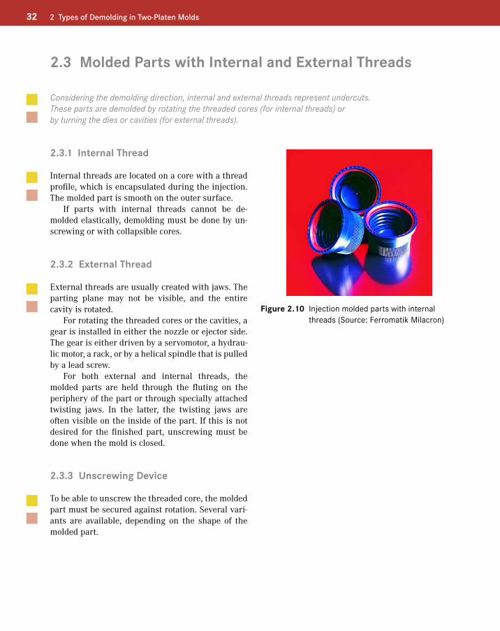
Figure 2.8 Injection molded part demolded with jaws (Source: Ferromatik Milacron)
When starting up the machine, the jaws of the mold can be opened via a slope and the molded part is released for demolding.
312.2 Molded Parts with Undercuts
2.2.4 Collapsible Cores
Collapsible cores are used when, besides threads, other undercuts must be released. These parts include tamper evidence bands, tear tabs on bottle caps or the like.
When using collapsible cores, one must ensure that the thread depth and the thread diameter are corre-lated. The thread depth is about 0.8 – 1.0 mm at a thread diameter of 28 mm. Therefore, no thread with a diameter of 28 mm and a thread depth of 3 mm can be produced with the collapsible core. However, this would always be possible using a ro-tary core.
This interdependence of thread depth and thread diameter results from the fact that the segments, which are arranged around a central core, can only fall so far inward until they lock themselves when the central core is pulled.
Applications can be found wherever the thread or a thread-like undercut on the molded part plays a minor role, such as covers used for resealable con-tainers.
Figure 2.9 Collapsible core (Source: HASCO)
In general, threads or thread-like under-cuts on injection molded parts with a diameter of between 15 mm and 500 mm can be produced with collapsible cores. When using collapsible cores, the plastic material being used is irrelevant.
32 2 Types of Demolding in Two-Platen Molds
2.3 Molded Parts with Internal and External Threads
Considering the demolding direction, internal and external threads represent undercuts. These parts are demolded by rotating the threaded cores (for internal threads) or by turning the dies or cavities (for external threads).
2.3.1 Internal Thread
Internal threads are located on a core with a thread profile, which is encapsulated during the injection. The molded part is smooth on the outer surface.
If parts with internal threads cannot be de-molded elastically, demolding must be done by un-screwing or with collapsible cores.
2.3.2 External Thread
External threads are usually created with jaws. The parting plane may not be visible, and the entire cavity is rotated.
For rotating the threaded cores or the cavities, a gear is installed in either the nozzle or ejector side. The gear is either driven by a servomotor, a hydrau-lic motor, a rack, or by a helical spindle that is pulled by a lead screw.
For both external and internal threads, the molded parts are held through the fluting on the periphery of the part or through specially attached twisting jaws. In the latter, the twisting jaws are often visible on the inside of the part. If this is not desired for the finished part, unscrewing must be done when the mold is closed.
Figure 2.10 Injection molded parts with internal threads (Source: Ferromatik Milacron)
2.3.3 Unscrewing Device
To be able to unscrew the threaded core, the molded part must be secured against rotation. Several vari-ants are available, depending on the shape of the molded part.
413.1 Distribution Systems
3.1.2.2 Hot Runner
3.1.2.2.1 Advantages of a Hot Runner
The hot runner is theoretically an extension of the injection unit. The hot runner should keep the liquid molten up into the mold cavity. It meets this requirement by guiding and heating the molten plastic until it reaches the mold cavity, with virtually no temperature and pressure losses.
The biggest advantage of the hot runner technology lies in waste-free injection and in good injection point quality. Disturbances in the production pro-cess by stuck sprue spiders in the open mold do not exist.
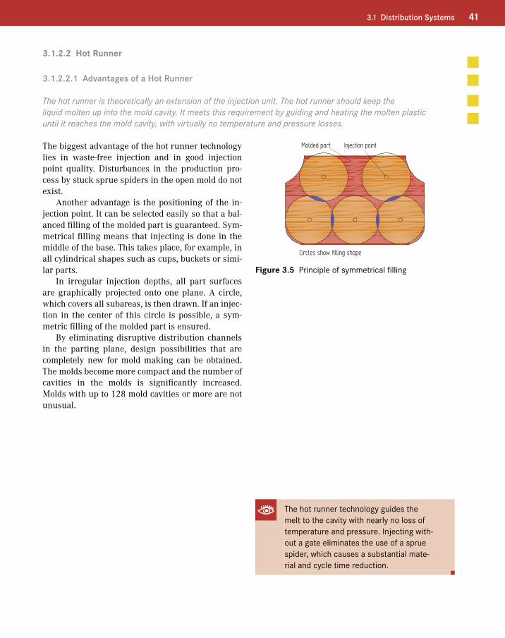
Another advantage is the positioning of the in-jection point. It can be selected easily so that a bal-anced filling of the molded part is guaranteed. Sym-metrical filling means that injecting is done in the middle of the base. This takes place, for example, in all cylindrical shapes such as cups, buckets or simi-lar parts.
In irregular injection depths, all part surfaces are graphically projected onto one plane. A circle, which covers all subareas, is then drawn. If an injec-tion in the center of this circle is possible, a sym-metric filling of the molded part is ensured.
By eliminating disruptive distribution channels in the parting plane, design possibilities that are completely new for mold making can be obtained. The molds become more compact and the number of cavities in the molds is significantly increased. Molds with up to 128 mold cavities or more are not unusual.
Molded part Injection point
Circles show filling shape
Figure 3.5 Principle of symmetrical filling
The hot runner technology guides the melt to the cavity with nearly no loss of temperature and pressure. Injecting with-out a gate eliminates the use of a sprue spider, which causes a substantial mate-rial and cycle time reduction.
42 3 Gate Technology
3.1.2.2.2 Hot Runner, Internally Heated
Molds with internally heated hot runners belong to the beginnings of the hot runner technology and are now hardly ever built. A disadvantage of internally heated systems is the complexity involved when changing color or material.
The hot runner technology originated from the idea of developing an internally heated distribution and gating system from an insulating runner, which pre-vents solidifying of the runners when starting the mold. Therefore, a heating system was installed and placed in the center of the distribution channels.
The knowledge that no hot material can escape in places where cold, solidified material is located was an important condition for the tightness of the system. A big disadvantage occurred for color or ma-terial changes. Streaks formed on the molded part because material particles dissolved in the surface layers of the insulating layer. To rule this out, the entire system had to be disassembled for every color and material change and the material located in the distribution system had to be removed, which is a very complex procedure.
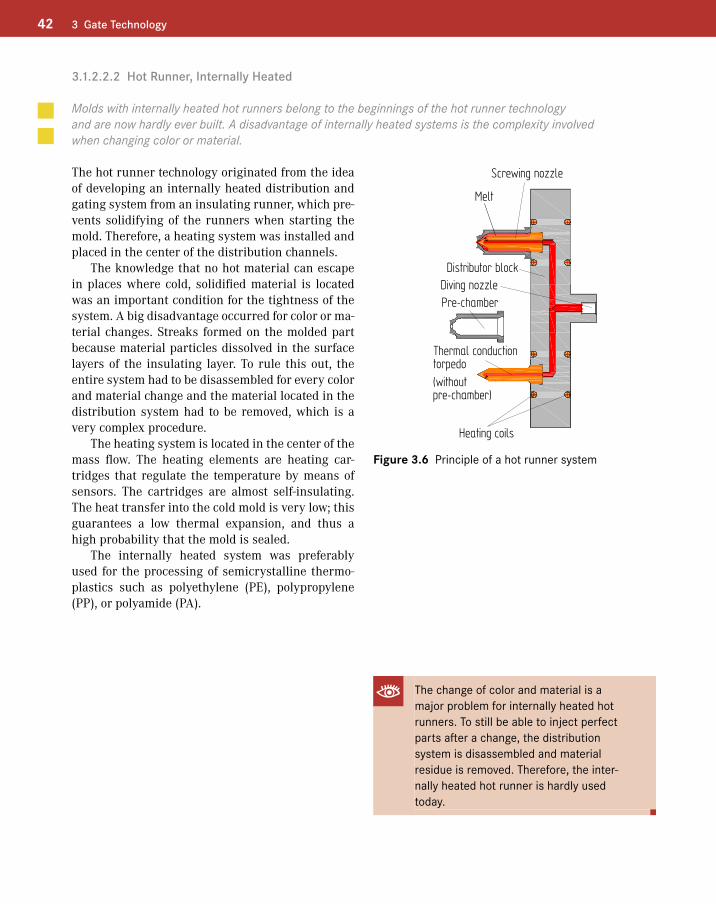
The heating system is located in the center of the mass flow. The heating elements are heating car-tridges that regulate the temperature by means of sensors. The cartridges are almost self-insulating. The heat transfer into the cold mold is very low; this guarantees a low thermal expansion, and thus a high probability that the mold is sealed.
The internally heated system was preferably used for the processing of semicrystalline thermo-plastics such as polyethylene (PE), polypropylene (PP), or polyamide (PA).
Melt
Screwing nozzle
Distributor blockDiving nozzlePre-chamber
(withoutpre-chamber)
Thermal conductiontorpedo
Heating coils
Figure 3.6 Principle of a hot runner system
The change of color and material is a major problem for internally heated hot runners. To still be able to inject perfect parts after a change, the distribution system is disassembled and material residue is removed. Therefore, the inter-nally heated hot runner is hardly used today.
453.1 Distribution Systems
3.1.2.2.4 Multiple Connections
There are three different types of multiple connections: 1) one nozzle for multiple injection molded parts, 2) multiple nozzles for one molded part, and 3) multiple nozzles for multiple molded parts.
One Nozzle for Multiple PartsThis type of nozzle, also called a hot edge nozzle, is designed such that multiple parts can be injection molded with one nozzle (see Section 3.2.2.3).
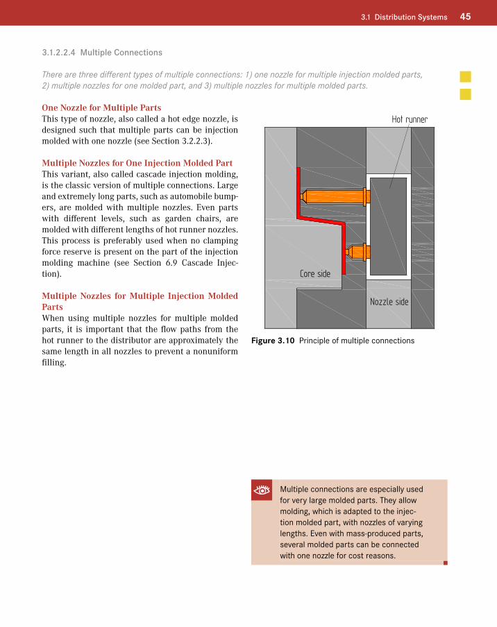
Multiple Nozzles for One Injection Molded Part This variant, also called cascade injection molding, is the classic version of multiple connections. Large and extremely long parts, such as automobile bump-ers, are molded with multiple nozzles. Even parts with different levels, such as garden chairs, are molded with different lengths of hot runner nozzles. This process is preferably used when no clamping force reserve is present on the part of the injection molding machine (see Section 6.9 Cascade Injec-tion).
Multiple Nozzles for Multiple Injection Molded PartsWhen using multiple nozzles for multiple molded parts, it is important that the flow paths from the hot runner to the distributor are approximately the same length in all nozzles to prevent a nonuniform filling.
Hot runner
Core side
Nozzle side
Figure 3.10 Principle of multiple connections
Multiple connections are especially used for very large molded parts. They allow molding, which is adapted to the injec-tion molded part, with nozzles of varying lengths. Even with mass-produced parts, several molded parts can be connected with one nozzle for cost reasons.
88 6 Special Designs
6.2.5 Rotary disk
Multi-component molds with rotary disks are used in all areas of the plastics industry. Depending on the application, rotary disks can be driven hydraulically or with a servomotor.
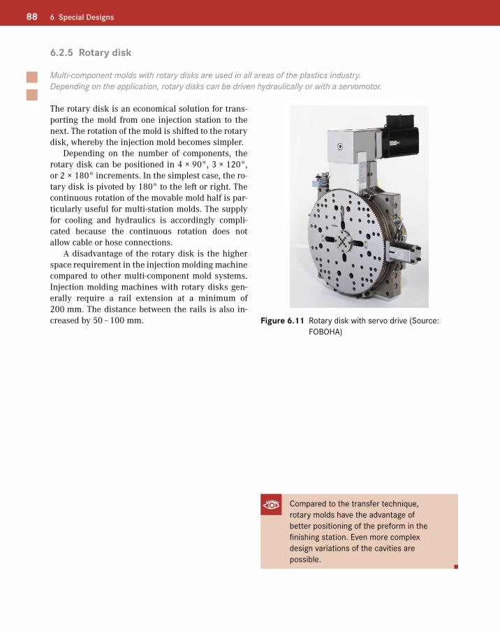
The rotary disk is an economical solution for trans-porting the mold from one injection station to the next. The rotation of the mold is shifted to the rotary disk, whereby the injection mold becomes simpler.
Depending on the number of components, the rotary disk can be positioned in 4 × 90°, 3 × 120°, or 2 × 180° increments. In the simplest case, the ro-tary disk is pivoted by 180° to the left or right. The continuous rotation of the movable mold half is par-ticularly useful for multi-station molds. The supply for cooling and hydraulics is accordingly compli-cated because the continuous rotation does not allow cable or hose connections.
A disadvantage of the rotary disk is the higher space requirement in the injection molding machine compared to other multi-component mold systems. Injection molding machines with rotary disks gen-erally require a rail extension at a minimum of 200 mm. The distance between the rails is also in-creased by 50 – 100 mm. Figure 6.11 Rotary disk with servo drive (Source:
FOBOHA)
Compared to the transfer technique, rotary molds have the advantage of better positioning of the preform in the finishing station. Even more complex design variations of the cavities are possible.
90 6 Special Designs
6.2.7 Cube Technology
The advantage of the cube technology over other mold technologies is that the number of cavities for the same machine size can be doubled. Or in other words: for the same production lot, the size of the machine is almost halved.
6.2.7.1 Stack Turning Technology
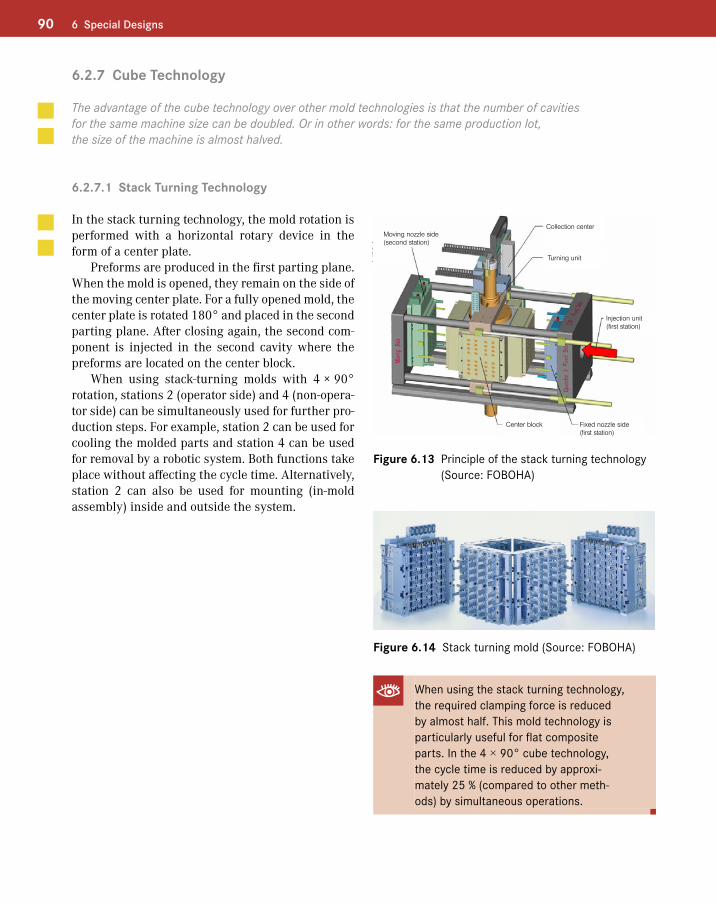
In the stack turning technology, the mold rotation is performed with a horizontal rotary device in the form of a center plate.
Preforms are produced in the first parting plane. When the mold is opened, they remain on the side of the moving center plate. For a fully opened mold, the center plate is rotated 180° and placed in the second parting plane. After closing again, the second com-ponent is injected in the second cavity where the preforms are located on the center block.
When using stack-turning molds with 4 × 90° rotation, stations 2 (operator side) and 4 (non-opera-tor side) can be simultaneously used for further pro-duction steps. For example, station 2 can be used for cooling the molded parts and station 4 can be used for removal by a robotic system. Both functions take place without affecting the cycle time. Alternatively, station 2 can also be used for mounting (in-mold assembly) inside and outside the system.
Moving nozzle side(second station)
Collection center
Turning unit
Injection unit(first station)
Center block Fixed nozzle side(first station)
Figure 6.13 Principle of the stack turning technology (Source: FOBOHA)
Figure 6.14 Stack turning mold (Source: FOBOHA)
When using the stack turning technology, the required clamping force is reduced by almost half. This mold technology is particularly useful for flat composite parts. In the 4 × 90° cube technology, the cycle time is reduced by approxi-mately 25 % (compared to other meth-ods) by simultaneous operations.
92 6 Special Designs
6.2.8 Tandem Mold
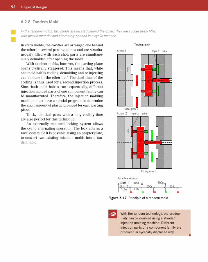
In the tandem molds, two molds are located behind the other. They are successively filled with plastic material and alternately opened in a cyclic manner.
In stack molds, the cavities are arranged one behind the other in several parting planes and are simulta-neously filled with each shot; parts are simultane-ously demolded after opening the mold.
With tandem molds, however, the parting plane opens cyclically staggered. This means that, while one mold half is cooling, demolding and re-injecting can be done in the other half. The dead time of the cooling is thus used for a second injection process. Since both mold halves run sequentially, different injection molded parts of one component family can be manufactured. Therefore, the injection molding machine must have a special program to determine the right amount of plastic provided for each parting plane.
Thick, identical parts with a long cooling time are also perfect for this technique.
An externally mounted locking system allows the cyclic alternating operation. The lock acts as a rack system. So it is possible, using an adapter plate, to convert two existing injection molds into a tan-dem mold.
Tandem mold
Action 1
Action 2
activeLayer 1
Layer 2 active
Parting plane 1
Cycle time diagram
Parting plane 2
Cavit
yCa
vity
Hot r
unne
r
Snorkel
Hot r
unne
rSnorkel
Figure 6.17 Principle of a tandem mold
With the tandem technology, the produc-tivity can be doubled using a standard injection molding machine. Different injection parts of a component family are produced in cyclically displaced way.
936.2 Multi-Component Molds
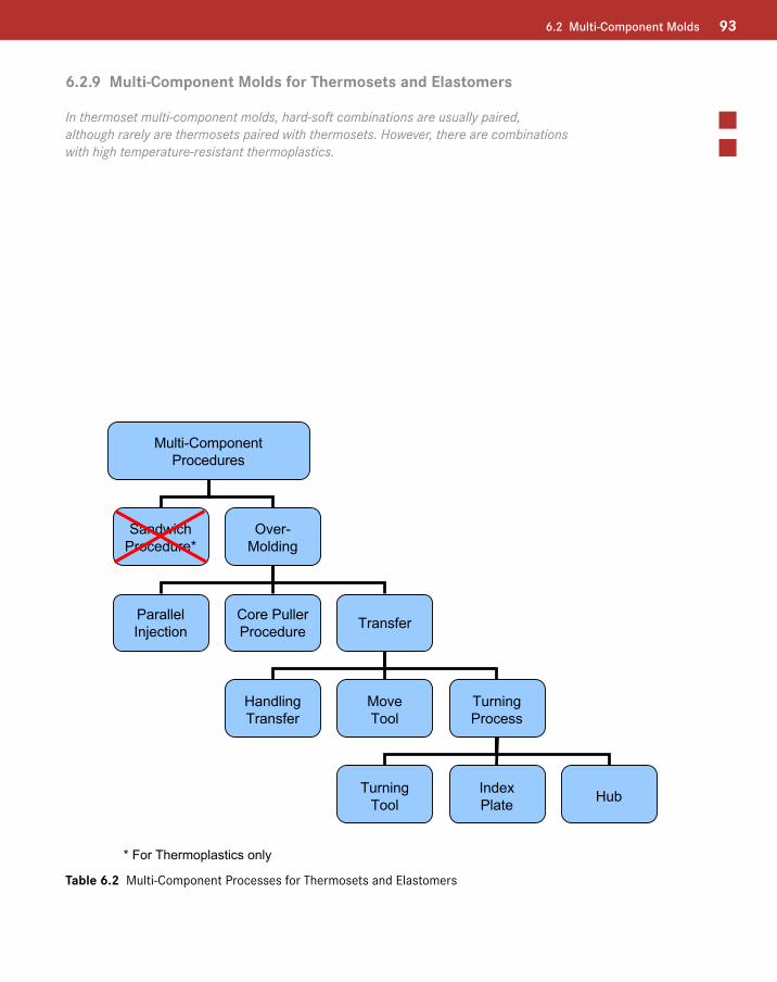
6.2.9 Multi-Component Molds for Thermosets and Elastomers
In thermoset multi-component molds, hard-soft combinations are usually paired, although rarely are thermosets paired with thermosets. However, there are combinations with high temperature-resistant thermoplastics.
Multi-ComponentProcedures
SandwichProcedure*
Over-Molding
ParallelInjection
HandlingTransfer
MoveTool
TurningProcess
TurningTool
IndexPlate Hub
Core PullerProcedure Transfer
* For Thermoplastics only
Table 6.2 Multi-Component Processes for Thermosets and Elastomers