understanding--- HVAC
39
Basic Concepts of Air Conditioning Prepared exclusively for COACH LEATHERWARE
-
Upload
faisal-saif -
Category
Documents
-
view
99 -
download
2
description
understanding--- HVAC
Transcript of understanding--- HVAC

Basic Concepts of Air Conditioning
Prepared exclusively
for
COACH LEATHERWARE

Slide 4
SOURCE OFCOOL AIR
• COIL •
HEAT
COILCOOL
AIR

Slide 5
TYPICAL ALL-AIR SYSTEM
S.A. DUCT
HEAT
COILCOOL
AIR
S.A.FAN

Slide 6
TYPICAL ALL-AIR SYSTEM
S.A. DUCT
HEAT
COILCOOL
AIR
S.A. TERMINAL
S.A.FAN

Slide 7
TYPICAL ALL-AIR SYSTEM
S.A. DUCT
HEAT
COIL
R.A. GRILL
COOLAIR
S.A. TERMINAL
S.A.FAN
WARM AIR

Slide 8
TYPICAL ALL-AIR SYSTEM
R.A DUCT
S.A. DUCT
HEAT
COIL
R.A. GRILL
COOLAIR
S.A. TERMINAL
S.A.FAN

Slide 9
TYPICAL ALL-AIR SYSTEM
R.A DUCT
S.A. DUCT
HEAT
COIL
R.A. GRILL
COOLAIR
S.A. TERMINAL
S.A.FAN
R.A.FAN

Slide 10
TYPICAL ALL-AIR SYSTEM
R.A DUCT
S.A. DUCT
HEAT
R.A. DAMPER
COIL
FILTER
O.A.DAMPER
FRESHOUTDOOR
AIR
R.A. GRILL
COOLAIR
S.A. TERMINAL
S.A.FAN
R.A.FAN

Slide 11
TYPICAL ALL-AIR SYSTEM
R.A DUCT
S.A. DUCT
HEAT
R.A. DAMPER
COIL
E.A.DAMPER
FILTER
O.A.DAMPER
FRESHOUTDOOR
AIR
EXHAUSTAIR
R.A. GRILL
COOLAIR
S.A. TERMINAL
S.A.FAN
R.A.FAN

Slide 12
Economizer
• Provides cooling to space when outdoor air temperatures are below 55 degrees
• Switches over automatically from mechanical cooling
• Adjusts R.A. and F.A. dampers to maintain space temp
• May incorporate enthalpy control• Mandatory in some states based on unit capacity

Slide 13
TYPICAL ALL-AIR SYSTEM
R.A DUCT
S.A. DUCT
CHILLEDWATERPUMP
HEAT
R.A. DAMPER
COIL
E.A.DAMPER
FILTERWATER PIPING
WATERCHILLER
O.A.DAMPER
FRESHOUTDOOR
AIR
EXHAUSTAIR
R.A. GRILL
COOLAIR
S.A. TERMINAL
S.A.FAN
R.A.FAN

Slide 14
TYPICAL ALL-AIR SYSTEM
CONDENSERPUMP
R.A DUCT
S.A. DUCT
CHILLEDWATERPUMP
HEAT
R.A. DAMPER
COIL
E.A.DAMPER
FILTERWATER PIPING
COOLINGTOWER
HEAT
WATERCHILLER
O.A.DAMPER
FRESHOUTDOOR
AIR
EXHAUSTAIR
R.A. GRILL
COOLAIR
S.A. TERMINAL
S.A.FAN
R.A.FAN
Slide 15
TYPICAL ALL-AIR SYSTEM
CONDENSERPUMP
R.A DUCT
S.A. DUCT
CHILLEDWATERPUMP
HEAT
R.A. DAMPER
COIL
E.A.DAMPER
FILTERWATER PIPING
COOLINGTOWER
HEAT
WATERCHILLER
BOILER
O.A.DAMPER
FRESHOUTDOOR
AIR
EXHAUSTAIR
R.A. GRILL
COOLAIR
S.A. TERMINAL
S.A.FAN
R.A.FAN

Slide 16
Equipment Types
• ROOFTOP PACKAGE UNIT • SPLIT SYSTEM• CHILLED WATER AIR HANDLER• VARIABLE AIR VOLUME (VAV)• AIR TO AIR HEAT PUMP• Life expectancy 10 to 12 yrs for rooftop and split systems• Expect increase in repair costs as equipment ages• Typically largest expense to operation of store, energy/repair costs• Repair or Replace?

Slide 17
Single Package Roof Top Unit
•Most common
•Entire hvac system is located on mall roof
•Most common to have roof leaks from roof curb, condensate overflow or roof punctures

Slide 18
Single Package Roof Top Unit
CONDR
COIL
COMP
FAN
HEAT
ELECTRICHEATER
S.A. DUCT
S.A.TERMINALR.A. DUCT
O.A.
E.A.
HEAT

Slide 19
Single Package Roof Top Unit
• Rooftop package unit• Mounted on adaptor
curb• Power exhaust and
economizer installed

Slide 20
Split System
• HVAC system split into 2 pieces• Condensing unit located on roof (houses
compressor, condenser coil, condenser fan motor)• Air handler located in space above ceiling (houses
blower assembly, evap coil, air filters)• Connected electrically and with refrigerant piping• Most prone to refrigerant leaks especially if long
distance between components• Many times refrigerant lines are buried in
construction and inaccessible

Slide 21
SPLIT SYSTEM
COIL
HEAT
AIR
R.A. DUCT
O.A.
E.A.
FAN
CONDR
COMP
CONDENSING UNIT
REFRIGERANTLINES
S.A. DUCT
POSSIBLEELECTRIC
HEAT
AIR HANDLINGUNIT
OPTIONALSUPPLEMENTARY
HEATINGSYSTEM
HEAT

Slide 22
SPLIT SYSTEM

Slide 23
Split System
• Air cooled condensing unit
• Compressor, condenser coil and condenser fans
• Connected to indoor air handler

Slide 24
VAV BOX
•Consists of VAV terminal box located in the space above ceiling
•May have supplemental blower motor for positive airflow to space
•May have air filtration
•Has a damper inside that opens and closes on demand from thermostat to allow more or less airflow to space
Variable Air Volume
Slide 25
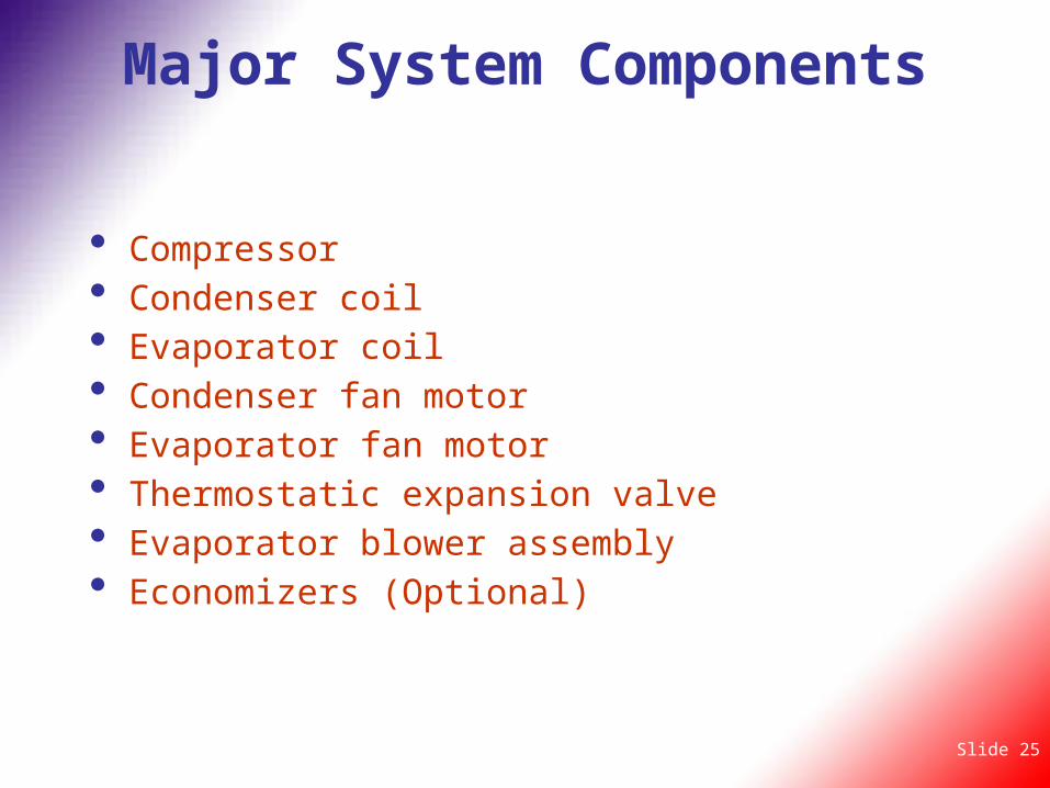
Major System Components
• Compressor• Condenser coil• Evaporator coil• Condenser fan motor• Evaporator fan motor• Thermostatic expansion valve• Evaporator blower assembly• Economizers (Optional)

Slide 26
HEAT REJECTION(“HIGH TEMPERATURE”)
85F
75F95F 55F
45F
CONDITIONEDSPACE
105F95F
HEAT GATHERING(“LOW TEMPERATURE”)
REFRIGERATIONMACHINE
(REFRIGERATION CYCLE)
35F
COOLINGTOWER
95F DB78F DB
HEAT
COMPRESSOR
COOLER
CONDENSER

Slide 27
Compressor
• This component is the heart of the system..• Pumps refrigerant and oil throughout
system• Separates the high pressure side of the
system from the low pressure side• If compressor fails, no cooling is possible

Slide 28
Condenser
• Condenser coil is what gets rid of the heat in the system
• Can be water or air cooled, however most are air cooled in retail application
• Located outdoors (air cooled)• Fins on coil are subject to corrosion in salt water
environment. Special coatings can be applied.• Fins are subject to damage from hail• Traps dirt and requires periodic cleanings

Slide 29
Evaporator Coil
• Provides cold air to the space• Located after the system air filters• Return air is blown over the coil and chilled• Removes moisture from air (condensate)• Traps dirt that gets past air filters, reducing
cooling capacity (95% is bacterial) • Requires periodic chemical cleaning

Slide 30
Evaporator Fan Motor
• Located behind condenser coil• Draws ambient air across condenser coil• System may have up to 4 or more motors based on
system capacity• Motors are direct drive with fan blades attached• Requires little if any maintenance (sealed
bearings)

Slide 31
TXV Thermal Expansion Valve
• Located at the evaporator coil• Provides the correct amount of refrigerant to the
evaporator coil for proper cooling• Separates the high pressure side of the system
from the low pressure side• Failure could cause compressor failure and loss of
system cooling capacity• Frequently overlooked in diagnosing system
problems• Requires manual setting of superheat for proper
operation.

Slide 32
Evaporator Blower Assembly
• Consists of:• Blower motor• Pulleys and fan belts• Bearings• Fan shaft• Fan wheels• Housings• Can be located indoors or outdoors

Slide 33
Control Types
• CONVENTIONAL THERMOSTAT• DIGITAL PROGRAMMABLE
THERMOSTAT• PNEUMATIC• LCD SYSTEM• MALL INTERFACE

Slide 34
Low Ambient Controls
• Low ambient controls• May be added to air cooled systems that must
operate when outdoor temperatures are below 55 degrees
• Cycles condenser fan/s to maintain correct system pressures
• Used when economizer is not present• Much less costly to install• Much more costly to operate

Slide 35
Conventional Thermostat
• Completely manual operation• Will maintain a single heat or cool setting• System must be switched from heat to cool• No energy savings• Will allow system to operate all night while store
is closed wasting energy• Easy to tamper with• Least expensive to install

Slide 36
Programmable Thermostat
• Provides auto changeover from heat to cool
• Provides up to 4 heat/cool settings per 24 hour period
• Can provide different weekend settings
• Keyboard can be locked out
• Set it and forget it

Slide 37
Pneumatic Thermostat
• Uses air provided by mall to operate thermostat
• Very commonly used with VAV systems• Least commonly found in malls• Parts are fairly expensive

Slide 38
LCD Thermostat
• Used in newer stores• Programmable type• Can be dialed into by monitoring company
for data

Slide 40
Rules Of Thumb
1HP = 1KW = 1KVA 1KW = 3413 BTU
1 Ton Cooling = 12,000 BTU 1 Ton = 400 CFM
Retail = 380 SQ FT/ Ton cooling
Delta T = 18°F across coil cooling Delta T = 25°F for heating
CFM = Building Volume in Cubic Feet
Minute/Air Change
Delta T = Difference between entering and leaving DB = ΔT

Slide 41
Servpro of Great Neck / Port Washington
For Further Information
Please Contact Us:
516-767-9600
ServproOfGreatNeck.com