Understanding Extrusion - hanserpublications.com 2nd Edition Chris Rauwendaal ISBNs...
12
Understanding Extrusion 2nd Edition Chris Rauwendaal ISBNs 978-1-56990-453-4 1-56990-453-7 HANSER Hanser Publishers, Munich • Hanser Publications, Cincinnati Sample Chapter 2: Instrumentation and Control
Transcript of Understanding Extrusion - hanserpublications.com 2nd Edition Chris Rauwendaal ISBNs...

UnderstandingExtrusion2nd Edition
Chris Rauwendaal
ISBNs978-1-56990-453-4
1-56990-453-7
HANSERHanser Publishers, Munich • Hanser Publications, Cincinnati
Sample Chapter 2: Instrumentation and Control

2 Instrumentation and Control
2.1 Instrumentation
Instrumentation is one of the most essential elements of an extruder. It is necessary to measure important process parameters to know what is going on in the extruder and to be able to control the process. Clearly, if the plastic melt temperature is not measured, it is impossible to control it. One reason that instrumentation is so important is that it is generally not possible to observe what happens inside an extruder. Without instrumentation on the extruder, we would be almost completely ignorant as to its inner workings. Instrumentation, therefore, can be considered as the “window to the process.”
When the extruder develops a problem, we are almost completely dependent on the instrumentation to determine what is happening inside the extruder. As result, good instrumentation is critically important when we troubleshoot extrusion problems.
2.2 Most Important Process Parameters
The most important process parameters are melt pressure and temperature. They are the best indicators of how well or how poorly an extruder functions. Process problems, in most cases, first become obvious from melt pressure and/or tempera-ture readings. Just think about what a doctor does when a patient comes into the office with a problem. Usually, the first check of the patient’s condition is made by taking blood pressure and body temperature. These are two good indicators of the functioning of the human body. In the same fashion, melt pressure and temperature are good indicators of how the extruder is functioning.
Other important process parameters are:
screw speed
motor load
barrel temperatures
die temperatures
power draw of the various heaters

20 2 Instrumentation and Control
cooling rate of the various cooling units
vacuum level in vented extrusion
These parameters relate just to the extruder. However, there are many more process parameters for the entire extrusion line and this, of course, depends on its specific components. Important parameters for any extrusion line are:
line speed
dimensions of the extruded product
cooling rate or cooling water temperature
line tension
Many other factors can influence the extrusion process, such as ambient tempera-ture, relative humidity, air currents around the extruder, and plant voltage varia-tions, among others.
2.2.1 Melt Pressure
Measurement of melt pressure is important for two reasons,
process monitoring and control
safety.
The diehead pressure in the extruder determines the output from the extruder. It is the pressure necessary to overcome the resistance of the die. When the diehead pres-sure changes with time, the extruder output correspondingly changes and so do the dimensions of the extruded product, see Fig. 2.1. As a result, when we monitor how the pressure varies with time, we can see exactly how stable the extrusion process is.
It is best, therefore, to plot pressure with a chart recorder or better, to monitor the variation of pressure with a computer data acquisition system. A simple analog or digital display of pressure is by far not as useful.
It is also critically important to measure pressure in the extruder to prevent serious accidents that can happen when excessively high pressures are generated. Very high pressures can be generated in the extruder and cause an explosion. The barrel can crack open under excessive pressure or the die may be blown from the extruder. Either situation is extremely dangerous and should be avoided. All extruders should have an over-pressure safety device, such as a rupture disk or a shear pin in the clamp holding the die against the extruder barrel. Even with such an over-pressure safety device, the extruder should have at least one melt pressure measurement because sometimes over-pressure devices do not work properly or are disabled. Pres-sure can build up very quickly without warning and cause a catastrophic explosion. When monitoring pressure, it is a good idea to use an automatic shutoff when the pressure reaches a critical value.

2.2 Most Important Process Parameters 21
Time
Time
Time
Pressure
Throughput
Dimension
Figure 2.1 Pressure, throughput, and dimension as a function of time
2.2.2 Pressure Transducers
There are a number of different pressure transducers. The most common ones in extrusion are the strain gage transducer and the piezo-electric transducer. The strain gage transducer can be either a capillary or a pushrod transducer. In these transduc-ers there are two diaphragms, one in contact with the plastic melt and one some dis-tance away from the hot plastic melt, see Fig. 1.2. The connection between the first and second diaphragm is hydraulic in the capillary type and a pushrod in the push-rod type. A strain gage is attached to the second diaphragm to measure the deflec-tion which can be related to the pressure at the first diaphragm.
Most capillary transducers are filled with mercury. Since the diaphragm of the transducer is quite thin, there is a danger of rupturing and leaking mercury into the plastic and into the workplace. Unfortunately, many transducers do not carry a label indicating that the transducer is filled with mercury, so adequate safety precautions are not always taken.
Another type of transducer is the pneumatic pressure transducer. It has good robust-ness, but poor temperature sensitivity, poor dynamic response, and average meas-urement error. The capillary transducer has fair robustness, fair temperature sensi-

22 2 Instrumentation and Control
Strain gage
Connection betweenthe two diaphragms
Thermally isolateddiaphragm
Diaphragm incontact with melt
Pressure
Velocities
Figure 2.2 Principle of the strain gage transducer
tivity, and fair dynamic response. The total measurement error varies from 0.5 to 3%, depending on the quality of the transducer. The pushrod is similar to the capillary transducer, except that is has poor temperature sensitivity and poor total error. The piezo-electric transducer has good robustness because of its relatively thick diaphragm, good temperature sensitivity, good dynamic response, and low measurement error. A comparison of different pressure transducers is shown in Table 2.1.
Table 2.1 Comparison of Various Pressure Transducers
Transducer type Robustness Temperature sensitivity
Dynamic response
Total error
Pneumatic good poor poor about 1.5%
Capillary strain gage fair fair fair 0.5 to 3%
Pushrod strain gage fair poor fair about 3%
Piezo-resistive good good good 0.2 to 0.5%
2.2.3 Temperature Measurement
Temperature is usually measured with thermocouple (TC) type temperature sensors. The principle of the TC is that when two dissimilar metals are connected and the temperature T of the junction is different from a reference junction at To, there is a voltage generated at the output end related to the temperature difference T-To, see Fig. 2.3. Since the temperature measurement is determined by the exact combina-

2.2 Most Important Process Parameters 23
tion of metal wires, it is important that the correct wires be used when wiring changes are made.
Another temperature sensor used in extrusion is the resistance temperature detector or RTD. The principle of the RTD is that the resistance of metals changes with tem-perature, so that by measuring resistance, the temperature can be determined. RTDs use a pure platinum resistance element to achieve high accuracy; platinum also has a linear relationship between resistance and temperature. Advantages of RTDs over TCs are higher output signal, better stability and accuracy, and no need for special lead wires or a reference junction. On the other hand, TCs are less expensive and are better for point sensing than RTDs.
A third type of temperature measurement uses infrared (IR) detectors. IR tempera-ture detection is based on the fact that objects emit radiation that changes with tem-perature. Thus, by measuring the radiation emitted by an object, the surface tem-perature of the object can be determined. IR temperature probes are useful because they allow non-contact temperature measurement. For instance, the temperature distribution across an extruded sheet can be measured using an IR probe without leaving any marks on the product.
IR probes can also be mounted in the extruder to measure melt temperature in the machine. These probes have a sapphire window and measure the radiation coming off the plastic melt. If the melt is opaque, the temperature measured is the melt sur-face temperature, which equals the metal wall temperature. If the melt is transpar-ent, the radiation from inner layers will also be detected, so that the measured tem-perature is the stock temperature averaged over a certain distance. The advantage of IR measurement is that the response is very rapid, in the range of milliseconds. A drawback of the IR measurement is its relatively high cost.
Metal A Metal C
Metal CMetal BT
Temperature input
Reference Junction
T0
(T-T0) mV
mV(+)
(-)MillivoltOutput
Figure 2.3 Principle of the thermocouple
2.2.4 Melt Temperature Measurement
The temperature of the plastic melt is often measured with an immersion TC. The probe protrudes into the melt and reads the temperature at the point of the TC junction. To avoid conduction errors, the junction should be thermally insulated

24 2 Instrumentation and Control
Figure 2.4 Various types of melt temperature probes from the base of the probe. One drawback of an immersion probe is that it changes the velocities in the channel. Since the velocities influence the melt temperatures, the immersion probe changes the actual melt temperatures. As a result, the measured temperature is different from the melt temperature at the same point without the immersion probe. Another drawback is that dead spots may occur behind the im-mersion probe; this can be detrimental in plastics that are susceptible to degradation. A number of different melt temperature probes can be used, as shown in Fig. 2.4.
A flush mounted probe measures the melt temperature at the wall, which is usually the same as the metal wall temperature. As a result, this melt temperature measure-ment is not the most useful. Another probe has a straight protruding design; these probes are also available with an adjustable depth so that temperatures at different positions in the channel can be measured. Yet another design has a tip on the probe that points upstream with the TC junction located in the tip. The benefit of this design is that there is minimal disturbance of flow where the temperature is meas-ured. This probe is also available with adjustable depth. It is also possible to run a bridge across the channel with several probes attached to it, which allows simultane-ous melt temperature measurement at several locations.
2.2.5 Barrel Temperature Measurement
The temperature of the barrel is usually measured with TC or RTD sensors pressed into the barrel; the sensors are generally spring loaded, see Fig. 2.5.
Figure 2.5 Spring loaded barrel temperature sensor
2.2 Most Important Process Parameters 25
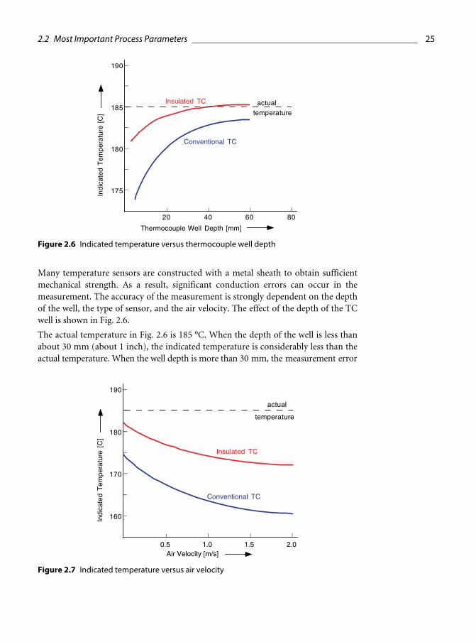
Figure 2.6 Indicated temperature versus thermocouple well depth
Many temperature sensors are constructed with a metal sheath to obtain sufficient mechanical strength. As a result, significant conduction errors can occur in the measurement. The accuracy of the measurement is strongly dependent on the depth of the well, the type of sensor, and the air velocity. The effect of the depth of the TC well is shown in Fig. 2.6.
The actual temperature in Fig. 2.6 is 185 °C. When the depth of the well is less than about 30 mm (about 1 inch), the indicated temperature is considerably less than the actual temperature. When the well depth is more than 30 mm, the measurement error
Figure 2.7 Indicated temperature versus air velocity

26 2 Instrumentation and Control
with the insulated TC becomes quite small. With the noninsulated TC, the indicated temperature is substantially less than the actual temperature, even with a well depth of 60 mm.
The effect of air currents around the extruder on the measured temperature is shown in Fig. 2.7. When the air velocity increases, the indicated temperature drops as much as 10 to 15 °C. The drop is larger with the conventional TC compared to the insulated TC. The practical result of this is that drafts around the extruder can cause substantial temperature measurement errors.
2.3 Temperature Control
In the extrusion process, good temperature control is important to achieve good process stability. There are two main types of temperature control, on-off control and proportional control.
2.3.1 On-Off Control
In on-off control, the power is either fully on or completely off. The temperature vs. time for on-off control is show in Fig. 2.8; the power vs. time is shown as well. When the measured temperature is below the setpoint, the power is fully on. As a result, the temperature rises. When it reaches the setpoint, the power shuts off; however, the temperature continues to increase for some time, up to several minutes. When eventually the temperature drops below the setpoint, the power turns on again. After the initial increase from room temperature, the temperature varies in a cyclical manner with a corresponding on-off cycling of the power.
The advantage of on-off control is that it is simple and the average temperature is right at the setpoint. The disadvantage is that the actual temperature always cycles with a variation that can be quite large, as much as 10 to 20 °C. The larger the extruder, the greater the temperature variation tends to get. Because of this, on-off control is not recommended in extrusion, except for non-critical processes.
2.3.2 Proportional Control
In proportional control, the power is proportional to the temperature within a cer-tain temperature region called the proportional band. The temperature versus time for proportional control is shown in Fig. 2.9; the power vs. time is shown as well.

2.3 Temperature Control 27
Figure 2.8 Temperature and power versus time in on-off control
Initially, when the machine heats up from room temperature, the power is fully on until the temperature reaches the proportional band. Within the proportional band, the power decreases as the temperature increases. If the emperature exceeds the pro-portional band, the power completely shuts off. When the temperature decreases in the proportional band, the power increases. The amplitude of the oscillations gradu-ally decreases and eventually the temperature and power reach a steady value.
The advantage of proportional control is that the temperature can be kept steady, unlike with on-off control. The power level can adjust itself exactly to the level that is required to maintain the correct temperature. A limitation of simple proportional control, or P-control, is that the temperature can be steady only as long as the ther-mal conditions around the extruder are constant. When there is an upset in the thermal conditions, such as a change in ambient temperature, the actual tempera-ture changes and the P-control is not able to correct it, see Fig. 2.10. In other words, in P-control, there is no reset capability.
In proportional control with integrating action, called PI-control, there is reset capa-bility, see Fig. 2.11. The controller integrates the difference between actual tempera-ture and setpoint and continues to act on the process until the ifference is zero.
overshoot
Figure 2.9 Temperature and power versus time in proportional control
28 2 Instrumentation and Control
Temperature
Upset
Time
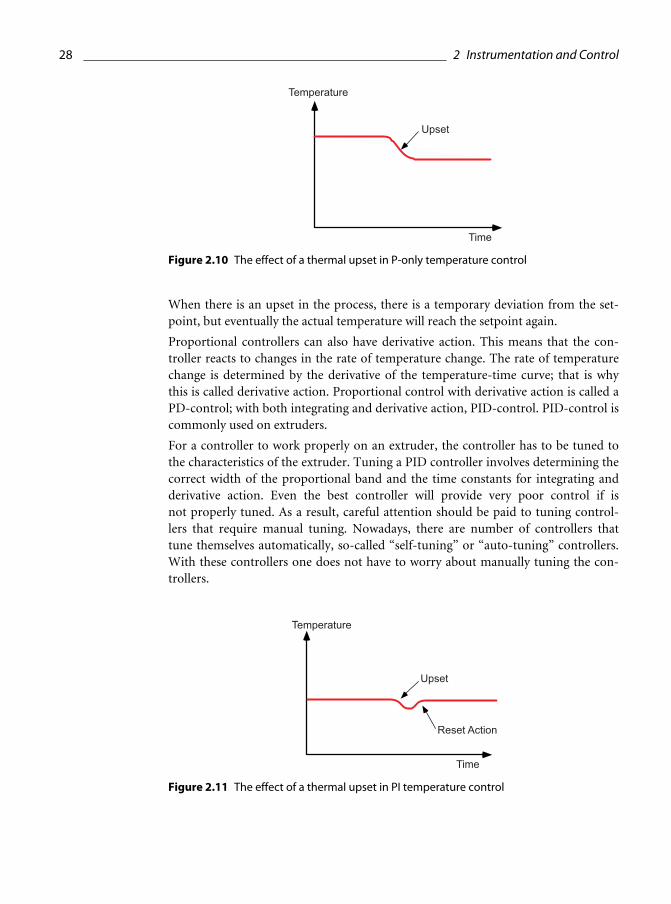
Figure 2.10 The effect of a thermal upset in P-only temperature control
When there is an upset in the process, there is a temporary deviation from the set-point, but eventually the actual temperature will reach the setpoint again.
Proportional controllers can also have derivative action. This means that the con-troller reacts to changes in the rate of temperature change. The rate of temperature change is determined by the derivative of the temperature-time curve; that is why this is called derivative action. Proportional control with derivative action is called a PD-control; with both integrating and derivative action, PID-control. PID-control is commonly used on extruders.
For a controller to work properly on an extruder, the controller has to be tuned to the characteristics of the extruder. Tuning a PID controller involves determining the correct width of the proportional band and the time constants for integrating and derivative action. Even the best controller will provide very poor control if is not properly tuned. As a result, careful attention should be paid to tuning control-lers that require manual tuning. Nowadays, there are number of controllers that tune themselves automatically, so-called “self-tuning” or “auto-tuning” controllers. With these controllers one does not have to worry about manually tuning the con-trollers.
Temperature
Upset
Time
Reset Action
Figure 2.11 The effect of a thermal upset in PI temperature control

2.2 Most Important Process Parameters 29
2.3.3 Fuzzy Logic Control
A relatively new method of control is fuzzy logic control or FLC. FLC is an artificial intelligence-based technology, designed to simulate human decision-making. It can be used in systems that use many variables to enhance process control. Developing a fuzzy logic application requires the generation of a knowledge base; this can be a time consuming process. It involves identifying:
process variables that are important in control
membership functions for each variable, such as high, low, and medium
fuzzy rules which define the knowledge of what to do about an observation, based on previous operating experience
FLC is slowly starting to be used in the plastics processing industry. It has already been applied a number of times in injection molding; fewer applications have been reported in extrusion. It has been shown that FLC can outperform conventional PID control if the knowledge base is sufficiently developed.