UNDERSTANDING DATA STRUCTURES February 1975...
227
UNDERSTANDING DATA STRUCTURES by Rob Gerritsen February 1975 DISSERTATION Submitted in partial fulfillment of the requirements for the degree of Doctor of Philosophy in Industrial Administration (Systems). Graduate School of Industrial Administration Carnegie-Mellon University Pittsburgh, Pennsylvania This research was supported in part by the Advanced Research ProjeCts Agency of the Office of the Secretary of Defense under contract F44620-73-C-0074. A William Larimer Mellon Fellowship provided personal funding.
Transcript of UNDERSTANDING DATA STRUCTURES February 1975...
UNDERSTANDING DATA STRUCTURES
by
Rob Gerritsen
February 1975
DISSERTATION
Submitted in partial fulfillment of the requirements for the degree of Doctor of
Philosophy in Industrial Administration (Systems).
Graduate School of Industrial Administration
Carnegie-Mellon University
Pittsburgh, Pennsylvania
P
£
This research was supported in part by the Advanced Research ProjeCts Agency
of the Office of the Secretary of Defense under contract F44620-73-C-0074. A
William Larimer Mellon Fellowship provided personal funding.
TO MY PARENTS
Alexander N. GerritsenJacqueline K. Gerritsen

UNDERSTANDING DATA STRUCTURES I
TABL___E_O_.FCONTENTS
ACKNOWLEDGf:MENT 3
ABSTRACI 4
LIST OF ILLUSIRAI-IONS 5
1 THEORY AND SUPPORT 7I. 1 [n|roduclion 71.2 Relevanl Literature ]l1.3 DBTG Data Bases 17
1.4 Matrices, Hierarchies, Relationships and Networks 22
2 DATA MANIPIJLATION LANGUAGE PROGRAMMER 272.1 ]nl roduc tion 27
2.2 lhe APG System 352.3 Program Generation vs a Generalized Interpreter 422.4 HI-IQ, the Query Language 452.5 Request Handler Assertions 572.6 A BNF Desc:riplion of tile Generated Procedure 632.7 Asserlions 772.8 A Frarne for the Semantics of Data Structures 89
2.9 Efficiency Considerations |042.10 Algol 1o COBOL Conversion 1092. I! Examples of Procedure Generation 115
3 DESIGN OF DAIA STRUCTURES 1343. l [nlrochlclion 134
3.2 Use of the Programmer 1373.3 Automatic Data Structure Design 1403.4 Defining Item Names 1433.5 Generating Assertions 144
¢,' "r '3.6 De,lgmng Record Relationships 1503.7 A Frame for Record Relationship Design 1553.8 Designing Record Conlenls ]643.9 [C_ample ] 693.]0 Allernalive Implementation I80
4 EXTENSIONS 1824.t E×tenslions to the DMLP 182
4.2 Extensions to the Data Struclure Designer 1904.3 Aulomalion of Data Base Update 1924.4 Dala Base Restructuring |94

UNDERS-fANDING DATA STRUCTURES 2Table of Contents
5 COST EFFECTIVENESS OF AUTOMATIC PROGRAMMING 197
5.1 Measures of Automatic Program Generation 1975.2 C,o,':_4Faclors in Programming 2005.3 Comparison of Dollar Costs 2025.4 E×ecution Costs 204
5.5 Cosl of Data Slructure Design 205
6 ON 1HE APPLICATION OF ARIIFICIAL INTELLIGENCE 207
6.t A Data Management Application 2086.2 Acquisition and Representation of Knowledge 213
7 THE RELA]-IONAt. AND NETWORK MODELS OF DATA BASES 2177.1 Introduction 217
7.2 Levels of Dala Structure Description 2177.3 Translation Approach 2197.4 Advantages of Translation 2207.5 lwo Implemented Translators 221
BIBLIOGRAPHY 222

UNDERSTANDING DATA STRUCTURES 4
ABSTRACT
Data management programmers are finding their jobs are getting tougherbecause of the gradual replacement of sequential data bases by network databases. In addition, lhere is a new job called "Data Administrator" for handlingthe data structure problems associaled with network data bases. The goal ofthis thesis is redclction of these data management tasks by developing andapplyinl:_ a practical lheory of data structure. To insure the practical flavor ofthis research, lhe Data Base Task Group (DBIG.) report has been selected as thespecification of tile data management system in which the applications function.
An implemented system that automates both information retrieval and data basedesign demonstrate_; the application of the theory. To do this, the theory iscapltired in a Frarne, a set of formal rules in the logic of programs. AnAutomatic Prograniming Generator (APG) compiles this Frame to an operatingprogram, lwo frames, resulting in two programs, are discussed. One of theseprograms [_enerates information retrieval procedure. The other programdesigns a data hase structure.
Both of these pioBrams accept relational queries (expressed in lhe HI-]Qlanguage) as input. These programs can be viewed as translators fromrelational d{_s{riptions to access path descriptions.
Pfogrammin_ and data structure design are cerebral tasks. Derivin 6 the Frameswhereby the programs understancl data structure so that these tasks can bereplicated was difficult. These difficulties are discussed for the benefit ofothers wl_o want to apply Arlificial intelligence.
This research is justified in practical terms: A comparison of manual and
automatic prograrnmin 8 costs shows a potential cost "eduction of up |o 98Z forautomatic programming.

UNDERSTANDING DAIA STRUCTURES 3
ACKNOWLEDGEMENT
I thank Professor .Jack R. Buchanan, my thesis supervisor and chairman of the
committee; his suggestions and direction were essential throughout. | also thank
Professor Charles 14. Kriebel and Professor Herberl A. Simon, members of my
thesis committee, for their excellent teaching and advice. Finally_ | am deeply
indebted to my wife, Joyce, who not only provided encouragement but also did
most of the typing and proofreading.

UNDERSTANDING DATA STRUCTURES 5
LIST OF ILLUSTRATIONS
1-1 Applicalions of data structure theory, 81-2 Simple DOCTOR-PATIENT data base. 191-3 Betler DOCTOR-PATIENT data base. 20
1-4 Stir,pie tabular reports. 231-5 ttierarchical report. 241-6 Hierarchical report (inverted from Figure 1-5). 26
2-1 Simple query with generated procedure. 292-2 System flows, 322-3 Average (ost per usage for generated and interpreted
programs in a production environment. 422-4 BNF: for the HI-IQ language. 48
2-5 two examples of retrieval conditions. 5[2-6 Query (PI) for the report of Figure 2-7. 5:32-7 A hierarchical-matrix report. 542-8 Templates for Request Handler assertions. 582-9 Possible values of tile TYPE parameter in LINKS. 592-10 Assertiorm describing the query of Figure 2-6. 622-11 A f]l'dF- descriplion of the generated procedure. 642-12 Cod(' generated for the condition of Figure 2-5. 722-13 Assertions used to describe the data base. 78
2-14 Assertions which indicate the results of singleprogram statements. 79
2-15 Other assertions. 81
2-16 A,gser|ions used to describe program blocks, 832-17 Assertions evaluated by LISP. 852-18 Standard LISP and Micro-Planner predicates
used in the rules. 8'7
2-19 ]ride× to Figures 2-8 and 2-13 through 2-18. 882-20 Operator (type SI) rules. 912-2/ The iteration rule. 94
2-22 Type $3 and $4 rules. 952-23 Rule and production correspondences. 992-24 Area search vs a SYSTEM owned set search. /05
2-25 Program PI (Figure 2-6)in Algol. I132-26 Program Pt in COBOL. 114
2-27 Inde× 1o the examples. 1162-28 A community medical data base structure. 1172-29 A sales data base structure, lib
2-30 Query P2. 12 l2-31 Prot:,t am P2. 1222-32 Query P3. 124
2-33 Program P3. 1252-34 QIJel'y 'P4. 127
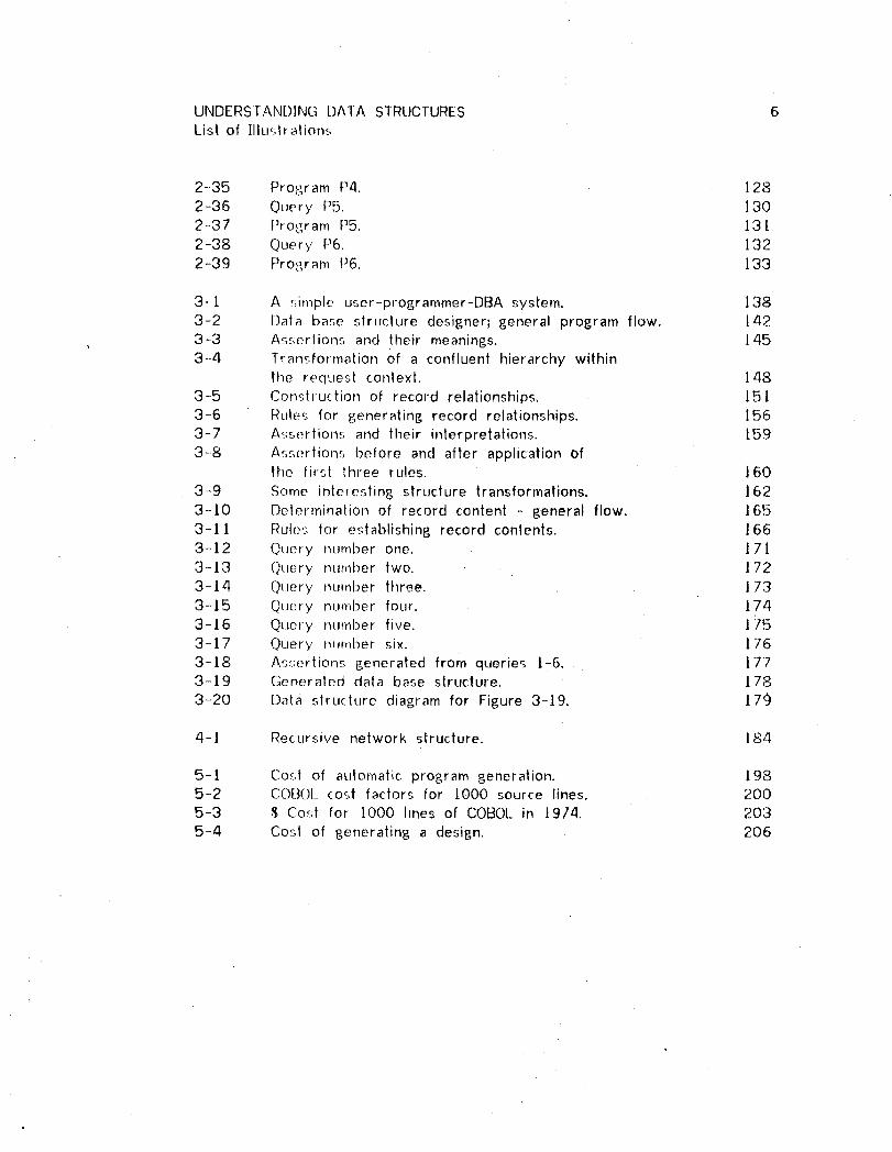
UNDERS]ANDING DATA STRUCTURES 6List of ]lluslralions
2-35 Program P4. ] 282-36 Query P5. ]302-37 Program P5. ]3l2-38 Query P6. 132
2-39 Program P6. ]33
3-1 A r;imple user-programmer-DBA system. ]383-2 Data base structure designer; general program flow. 1423-3 As-_,erlions and their meanings. ]453-4 Transformation Of a confluent hierarchy within
tile request context. ]483-5 Conslruction of record relationships. 1513-6 Rulet_ for generating record relationships. ]563-7 Assertions and their interpretations. 1593-8 Ar, serlions before and after application of
tile first three rules. 160
3-9 Some interesting structure transformations. 1623-10 Determination of record content - general flow. 1653-1] Rule':; for establishing record conlents. 1663-12 Query nLimber one. 1713-13 Query number lwo. 1723-14 Oqlery number three. 173
3-15 Query numl)er four. 1743-16 Query number five. 1753-17 Query mm_ber six. 176
3-18 Assertions generated from querie£ I-6. 17173-19 Generaled data base structure. 178
3-20 Data structure diagram for Figure 3-19. 179
4-1 Recursive network structure. ]84
5-1 Co':.| of atJtoma|ic program generation. 1985-2 COB(_)L (o__,t factors for 1000 source lines, 2005-9 $ Co._4 for 1000 lines of COBOL in 1974. 203
5-4 Cost of generating a design. 206

UNDERSTANDING DATA STRUCTURES 7
1 THEORY AND SUPPORT.
].]. IntrodLJction.
Data management programmers are finding their jobs are getting tougher
because of lhe gradual replacement of sequential data bases by network data
bases. In addilion, there is a new job called "Data Administrator" [CODASYL
197/a] for handling the data structure problems associated with network data
bases. The goal of ¿his thesis is reduction of these data management tasks by
developing and applying a practical theory of data structure. To insure the
practical flavor of this research, ] have selected the Data Base Task Group
(DBTG) [CODASYL 197ia] report as the specification of the data management
system in which the applications function.
An implemented system that automates both information retrieval and data base
design demonstrates the application of the theory. To do this, the theory is
captured in a Frame, a set of formal rules in the logic of programs. An
Automatic Programming Generator (APG) compiles this Frame to an operating
program. ] will discuss two Frames that resulted in two programs. One of
these program,.; generates information retrieval programs. The other program
designs a data base structure.

UNDERSTANDING DATA STRUCTURES 8
I.l Introduction.
I DDLDESCRIPTION
DMLP 1 _ COBOL/DMLPROCEDURE
I QLJERY
I QUERY
---..._STRUCTUREDESIGNER
QUERY
Figure I-I. Applications of data structure theory.
Figure l--I ilhJstralesthese two programs, a Data Manipulation Language
Programmer (DMLP) and a structure designer. The DMLP translates a query to
COBOL. procechJre augmented by Data Manipulation Language (DML). To do this
it uses a [)ata Definition Language (DDL) [CODASYL 1971a] description of the
da|a base struclure.
The DMLP is dala base independent. The Frame that defines the DMLP contains
only general knowledge of data structures and programming. Specific
knowledge of a particular data base is contained in the DDL description.

UNDERSTANDING DATA STRUCTURES 9l.t Introduction.
Note that the DMLP does not perform the information retrieval described in the . .
query. II only generates a procedure that will retrieve the desired information
when it is executed.
The other program in Figure 1-] generates a DDL description from a set of
queries; it tries to find a design that captures all data relationships implied by
the queries.
The logical slruclure of the data base is of primary concern in this thesis.
Actual physical mapping of the data to thai structure will. not be considered.
Nor does the system consider certain data characteristics including data type,
retrieval frequency, update volatility and data volume.
The accomplishments of this thesis are as follows:
Chapter |.. presents general concept_; (theory) of networkdata structures.
Chapter 2:
(a) presents a Frame, a formal (axiomatic)representation of programming for DBTG data base%and I--I]--IQ,an interactive query language.(I)) discusses compilation of (a) by the APGenabling it to write information retrieval procedures.
Chapter 3:(a) presents a new algorithm for DBTG data basedesign including a Frame, a formal (axiomatic)representation of the design process.
(b) discusses compilation of (a) by the APGenabling it to design data structures.

UNDERSIANDING DATA STRUCTURES 10I. t Introduction,
Chapter 4: ,';uggesls further research including extension ofthe techniques used in Chapters 2 and 3 to otherdata management tasks.
Chapter 5: demonstrates the economio validity of theapproach - a potential programming cost reductionof up to 98Z.
Chapter 6: pre_,ents some remarks on the difficultiesencountered in lhis research and the expected
impact on relaled research.
Chapter 7: claims that lhis research bridges the gap betweentt_e relalional and network models of data bases.

UNDERSTANDING DATA STRUCTURES ] I
1.2 _R_el__e_r__)l_LL[ei-._:II_ure___=
This work is related to:
a) Aulomatic and/or structured programming,
b) Data bases and their implementation,
c) Non-procedural information retrieval.
The following discussion wilt proceed in the above sequence. Obviously there is
no clean boundary between some of these fields: Category "c" bridges
categories "a" and "b".
t.2. t Aulotn?.!i_£ and_structured programminp=
Automatic pro{;ramming systems have always used theorem provers of some
sorl. PROW [Waldinger and Lee t969] is a clear example, being based on a
predicale calculus theorem prover. Preceding lhis effort by several years was
Simon's I-leurislic Compiler [Simon 1961; also in Simon and Siklossy 1972] which
was based on the General Problem Solver [Newell, Shaw and Simon /960].
Although the terminology used by Simon does not imply the use of a theorem
prover, it is nol wery difficult to view GPS as a theorem prover: The "Means-End
Analysis" done by: GPS is goal driven as are some theorem provers; GPS
operalors, which may be viewed as rules of inference, achieve the goal by
removing differences.
Hewitt [ttewitl t971] proposed a programming language called PLANNER in which

UNDERSIANDING DATA STRUCTURES 121.2 Relevant literature.
the rules for proving theorems (or achieving goals) may be expressed as part of
the program. This facilitates the implementation of theorem provers in other
probrem domains (t,uch as automatic programming or natural language
understanding) because it removes a level of interpretation. Hewitt's ideas
were implemented in a programming language called Micro-Planner [Sussman and
Winograd 1972].
Hoare's development of a system of logic for the definition of the semantics of
programming languages [Hoare 1969] has proven useful for automatic
programming. So has the concept of structured programming [Dahl, Dijkstra and
Hoare t972]. The logical basis of the automatic programming syslem reported
in [Buchanan and Luckham J974; Buchanan 1974] was described using the Hoare
logic. Thi-._ system contains a compiler that translates a non-procedural
definition of a programming environment (whose elements correspond in form to
statements in Hoare's logic of programs)into Micro-Planner theorems and LISP
functions.
A program resulting from such a compilation is a program generator lhat is
capable of generating specific programs satisfying given sets of input-output
assertions, The program generator of Chapter Two and the data base designer
of Chapter Three were formed by an extended version of the aforementioned
system.

UNDERSTANDING DATA STRUCTURES 131.2 Relevant Literature.
1.'2.2 Dala ba_.es and their implementation.
The retrieval programs that can be generated are capable of retrieving
information from da|a bases which allow the storage of highly inter-related data.
Such data bases are typically called network, hierarchical, or relational data
bases, and they are quite different from the set of sequential files that
traditionally formed a data base.
There exist,.; some disagreement [Codd and Date 1974; Date and Codd J974;
Jardine t974] regarding differences/similarities of the network and relational
models of data bases. Some comments relevant to this discussion and the
impact of this thesis on the disagreement are presented in Chapter Seven. It is
generally agreed, however, that hierarchical data bases are a subclass of the
network type.
The network data base was commercially developed at General Electric
[Bachman and Williams 1964; Bachman 1965; General Electric 1965]. A specific
notation for describing the structure of a network data base has been
developed [Bachman 1969]. An attempt at standardization of this type of data
base was made by lhe Data Base Task Group [CODASYL 1971a]. Several
commercially available implementations of this standardized design are available,
for example [Xerox 1970]. A generalized hierarchical data base system has
been implemenled at Bell Laboratories [Gibson and Stockhausen |973].

UNDERSTAND[NG DATA STRUCTURES 141.2 Releval_t Literature.
In a nelwo_k data base such as the DBTG specification, the relations between
data must be explicitly named and defined. ]he DBTGterminology for a relation
is a SET. The elements of a SET are linked, hence the "network" characteristic
of such data bases. Codd [Codd 1970, 1972a, 1972b] and Childs [Childs 1968]
have developed what is termed the relational model of data bases. ]n this
model a relation is a defined template of related data elements. The user of a
relational data base defines elements and templates rather than elements and
the links between them as must be defined for a DBTG type data base.
A discussion of other data base implementations can be found in [CODASYL
197[b]. Some of tile systems discussed in tt]e CODASYL report utilize
sequential or simple hierarchical data bases that do not present many of the
complexities encountered with more structured data bases. Information
retrieval systems based on the relational model have been implemented at ]BM
[Boyce, Chamberlin, King and Hammer ]973].
1.2.3 Non-p_rocedural information retrieval.
"Non-procedt_ral", "problem statement", and "goal oriented" languages are often
discussed for information retrieval because, it is hoped, such a language will
allow the information user direct access to the data without the intervention of
a prograrnmer 1o translate his needs to a computer procedure (e.g. the
retrieval program). Many such non-procedural languages have been developed
and some IbM are more well known are discussed in [CODASYL 1971b] and in
UNDERS'[ANDING DATA STRUCTURES 15].2 Relevanl Literature.
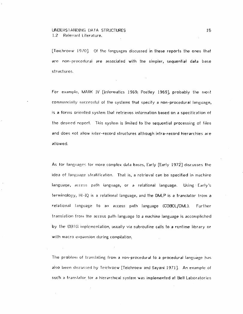
[Teichroew 1970]. Of the languages discussed in these reports the ones that
are non-procedural are associated with the simpler, sequential data base
structures.
For example, MARK ]V [Informatics 1969; Postley 1969], probably the most
commercially successful of the systems that specify a non-procedural language,
is a forrns oriented syslem that retrieves information based on a specification of
the desired report. This system is limited |o the sequential processing of files
and does not allow inter-record structures although intra-record hierarchies are
allowed.
As for- langL,ages for more complex data bases, Early [Early 197;_] discusses tile
idea of language stralification. That is, a retrieval can be specified in machine
language, access path language, or a relational language. Using Early's
terminology, _tl-4Q is a relational language, and the DMLP is a translator from a
relational language to an access path language (COBOL/DML). Further
translalion from the access path language to a machine language is accomplished
by the DBfG implementation, usually via subroutine calls to a runlime library or
with macro e×pansion during compilation.
The problem of translating from a non-procedural to a procedural language has
also been discus, seal by Teichroew [Teichroew and Sayani 1971]. An example of
such a tran_.lator for a hierarchical system was implemented at Bell Laboratories

UNDERSTANDING DATA STRUCTURES 161.2 Relevant Literature.
[Puerling and Roberts 1973].
The idea of pro(et, sing a network by attacking a single hierarchy at a time
comes from the work of Lavallee and others [Lavallee, Ohayon and Sauvain
undated]. Their work also introduces the important concept of confluent
hierarchies, the building blocks of network dala bases.
1.2.4 Data !?]_.e d_,ip_n_.
[Teichroew and Sayani 197/] briefly discuss the goal of automating the data
base design lat, k. With the exception of the program discussed in Chapter 3,
little progress to date has been reported.

UNDERSTANDING DATA STRUCTURES 17
1.3 DBTG Data Bases.
The CODASYL Data Base Task Group [CODASYL 1971a] specified a direct access
data base management system of the network type. This is a so called
"general" system, the idea being that many different specific data management
applications will be implemented that make use of the general system. General
systems very similar to the DBTG specification have been implemented by
Honeywell Information Systems, called Integrated Data Store (IDS) [General
Electric 1965], and by Xerox, called Data Management System (DMS) [Xerox
1970].
The DBTG report specifies two user interfaces. One is the Data Definition
Language (DDL) whereby the data base structure is described in a Schema; the
other is the Data Manipulation Language (DML) whereby actual data access and
storage is achieved. The schema functions as a map for the data management
library routines. These routines are called by the DML statements in the
application program.
DBTG data base structure is defined in terms of "records", "items", "sets",
"groups", and "areas". Records consist of a concatenation of items. The set is
a relation between records. A set always has a unique owner record and one
or more member records. A set defines a one-to-many relationship in the data
base between the owner record and member records. A particular set

UNDERSTANDING DATA STRUCTURES 181.3 DBTG DataBases.
occurrence in the data base includes at most one occurrence of the owner
record. A group is a subdivision of a record, i.e. a smaller concatenation of
items. An area is a subdivision of the data base.
i.,_cord access in a DBTG system occurs in one of three ways_ direct, calculated,
or via a set relationship. A record can be directly accessed if its storage
address is known. Calculated access is possible if the values of those items
from which the storage address can be calculated are known. Records for
which calculated access is desired must be so specified when the records are
defined in the Schema. The items that are to be used in the calculation must
also be defined in the Schema. Set relationship accesses allow the finding of an
owner of a set previously accessedvia one of its members or the finding of the
first, last, next, or prior member of a set previously accessed.
Data Structure (DS) diagrams illustrate the structure of DBTG data bases
[Bachman 1969]. In these diagrams, boxes are used to represent records and
arrows represent sets. The arrow always emanates from the owner of the set
and points to the set member. For example, Figure 1-2 illustrates a simple data
base structure defined with two record types and one set. Although this data
base can contain many DOCTORrecords, each TREATING set occurrence will
contain exactly one DOCTORrecord. On the other hand, the set occurrence may
contain many PATIENT records, one record for each patient being treated by the
doctor specified in the DOCTORrecord.

UNDERSTAN[]ING DATA STRUCTURES 191.3 DBTG Data Bases.
DOCTOR
DOCNO
TREAIING
PATIENT
Figure 1-2. Simple DOCTOR-PATIENT data base.
In these diagrams, underlined items represent calculated keys. Therefore a
DOCTOR record can be retrieved using a DOCNO value.
The data base tdructure in Figure 1-2 does not allow more than one doctor per
patient unless patient records are duplicated. This problem does not occur with
the data base of Figure 1-3.

UNDERSTANDING DATA STRUCTURES 201.3 DBTG Data Bases.
PATIENT DOCTOR
DOCNO
\ //
• TREATMENT /TREATINGi
/
/
TREATMENT
Figure i-3. Better DOCTOR-PATIENTdata base.
This structure, called a confluent hierarchy [Lavalle et at undated], captures a
two-way hierarchy. In Figure 1-3 a patient may have many associated
treatments and therefore many associated doctors, and a doctor may be
performing many treatments, each with an associated patient.
The DDL description of the structure of a data base contains the same
information as a data structure diasram.
A programmer uses DML commands to move through the data base. For
example, to find the doctor with identifying number 100, the program would
contain the following COBOL and DML statements (for the data base of Figure
1-2)"
MOVE tO0 TO DOCNO.FIN[]DOCTOR RECORD.

UNDERSTANDING DATA STRUCTURES 211.3 DBTG Data Bases.
Executing ltle stalement
FIND FIRSq- PATIENT RECORD OF TREATING SET
will locale a pa|ient being treated by doctor 100, if it is executed following the
statemenl that found the doctor. The statement
FIND NEXT PATIENT RECORD OF TREATING SET
can then be repeatedly executed to find all of the patients of doctor 100.
The user proBram must check an error code to determine when all patient
records in the set have been found.
Notice thai tllere is a context which effects communication between the program
and the DI3]G r.;y.,>tem. The DBTGreport calls the context "current". When the
current owner of the TREATING set is doctor 100, then all commands to find
patients in the TREATING set will find only patients of doctor 100.

UNDERSTANDING DATA STRUCTURES 22
1.4 Matrices, Hierar(:hies_ Relationships and Networks.
This section presents the theory on which valid data base programming must be
based. The knowledge needed by a programmer to understand data struclures
and their tran,:,formations is set forth. These data structure transformations can
occur whenever data moves into and out of the data base.
The assumption is made lhat people manipulate information in either matrix or
hierarchical form (or a combination of the two). This assumption may not be
correct in all cases but within the realm of tabular reports, forms, etc (e.g. a
business environment), this assumption holds for a large portion of the
information transfers that occur. Prose reports also follow a hierarchical
structure [Shelter 1958]. Further evidence of this hierarchical structuring is
the decimal numbering of paragraphs in technical documents (such as this one).
A Simple tabular report (Figure l-4) can be viewed as a matrix (e.g. each line
is a row vector and each column is a column vector). Typically, each column
vector can be as.'_ociated with an attribute; whereas each row vector is
associated with some type of simultaneous occurence of values for the several
attributes. Frequently such simultaneous value occurences are called records.
In both report__, the atlributes (columns) have been labeled. The simultaneous
value occurences in the first report might be "patients", those in the second
report "doctors".

UNDERSTANDING DATA STRUCTURES 23
1.4 Matrices, ttierarchies, Relationships and Networks.
[',lAME AGE DIAGNOSIS
SMITH 48 BOTULISMJONES 22 APPENDICITISWILLIAMSON 3t MISCARRIAGE
NAME AGE SPECIALTYFREDERICKS 4J G.P.BROWN 36 HEARTSI.ENDER 52 GEN SURGERYB[ I.JE 49 GYNECOLOGY
Figure t-4. Simple tabular reports.
Note thal these sirnple tabular (matrix)reports can be (and frequently are)
combined into hierarchically organized reports as in Figure [-5. The
hierarchical report contains additional information about relationships between
records, information not available from either report in Figure 1-4. General
purpose systems (such as MARK IV [|nformatics J969], RPG or COBOL Report
Writer) usually allow several hierarchical levels. MARK IV, for example, allows
up to nine levels.
If one thinks of a hierarchy as an upside-down tree (with the repeating records
forming the branches), then the notions of above and below can be used for
describing the Merarchical relationships between record types. For example, in
the hierarchy present in the report in Figure 1-5, the doctor records are
hierarchically above the patient records.

UNDERSTANDING DAIA STRUCTURES 24
1.4 Matrices, Hierarchies, Relationships and Networks.
FREDERICKS ZlI G.P.SMITH 48 BOTULISMJONES 22 APPENDICITIS
BROWN 36 HEARTSMITH 48 BOTULISM
SLENDER 52 GEN SURGERY
JONES 22 APPENDICITIS
BLIJE 49 GYNECOLOGYW]LLIAMSON 31 MISCARRIAGE
Figure [-5 Hierarchical report.
Once lhe e×istence of a hierarchy is recognized it becomes possible and
frequently useful to calculate statistics based on a hierarchy. Examples
applicable to the hierarchy illustrated in Figure 1-5 are "number of patients per
doctor", "average patient age per doctor", "maximum patient age per doctor",
etc. These slatislics all become attributes of doctor records; e.g., the average
patient age attribute for doctor Fredericks has a value of 35. Notice that in a
certain sense these statistics migrate upward in the hierarchy. The information
from which they are calculated is located within a set of patient records, yet the
calculated value becomes an attribute of the doctor record that is hierarchically
above the patient record.
By introducing the concept of a universal record that is above all other records
in any hierarchy, it becomes possible to associate with the universal record all

UNDERSTANDING DATA STRUC'[URES 25
1.4 Matrices, Hierarchies, Relationships and Networks.
universal attributes such as the total number of doctors (which in Figure 1-5
has a value of four), lhe average doctor age, and the average patient age.
Attributes also migrate downward. For example, the doctor name is also a
patient atlribule; e.g., the palient Williamson has the attribute that her doctor's
name is Blue. Tile concept of downward migration is an important one to any
automatic system because it reduces the amount of knowledge about the
structure that a u_er needs to have. A system that understands downward
migration can allow one user to assume thal the patient record contains the
doctor's name while another user can assume a hierarchical relationship.
it is also po,:;t,iMe to invert a hierarchy. A,n example of the result of an
inversion is given in Figure 1-6, where the hierarchy of Figure 1-5 has been
inverted. Notice that lhe informational content of the reports in Figures }--5
and I--6 is idenllcal (assuming that patients and doctors are uniquely identified
by their name._,), yet time usefulness of time reports (to a particular user) is
strikingly different. Similarly, the index to a book or document is an inversion
of the prose it accompanies.
The confluent hierarchy discussed in section 1.3 is the structure used in a
network dala base to simultaneously store a hierarchy in both inverted and
original form.
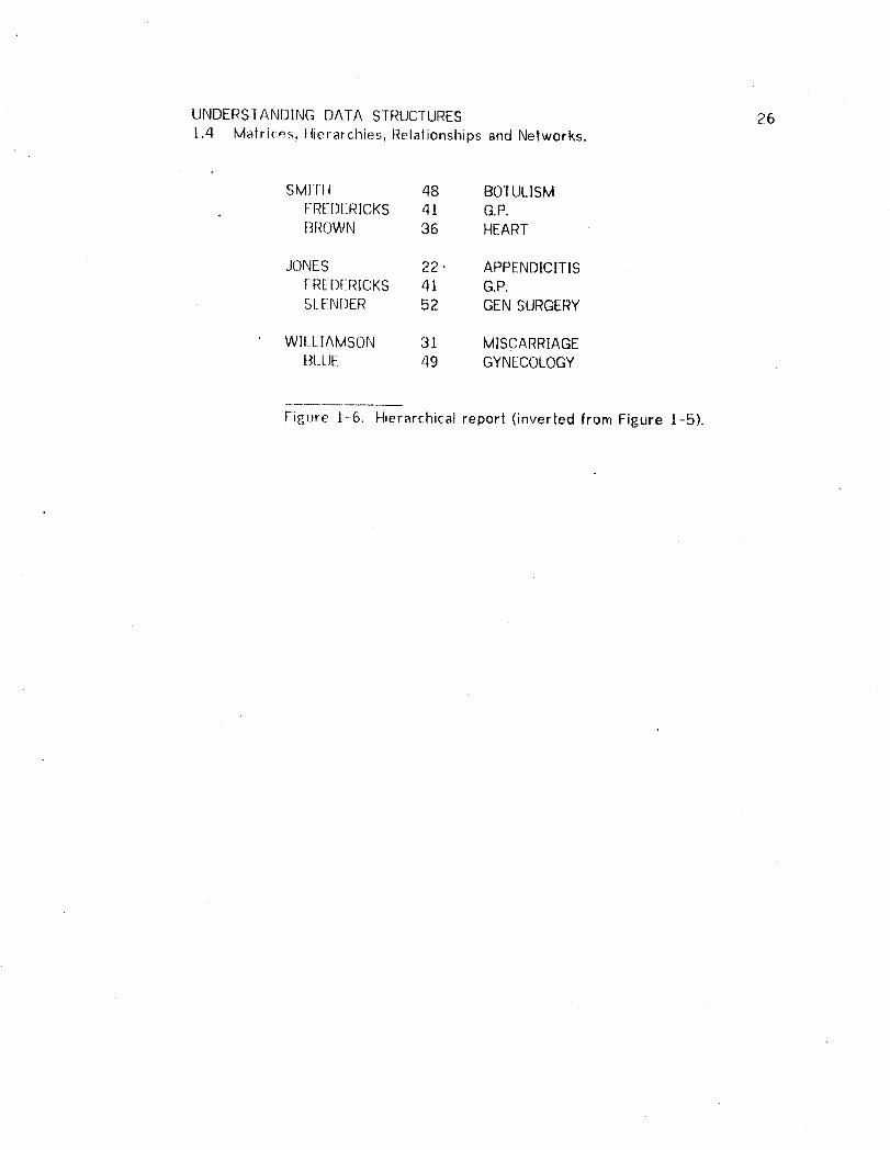
UNDERSTANDING DATA STRUCTURES 261.4 Matrices, tlierarchies, Relationships and Networks.
SMIrll 48 BOTULISMFRE[]ERICKS 41 G.P.BROWN 36 HEART
JONES 22 • APPENDICITISFREDERICKS 41 G.P.SLENDER 52 GENSURGERY
WII.LIAMSON 31 MISCARRIAGEBLUE 49 GYNECOLOGY
Figure 1-6. Hierarchical report (inverted from Figure t-5).

UNDERSTANDING DATA STRUCTURES 27
2 DATA MANIPUIATION LANGUAGE PROGRAMMER,
2.1 Inlroduction
This chapter will describe a computer program, called the Data Manipulation
Language Programmer (DMLP), that can genera|e a COBOL Procedure Division
corresponding to an information retrieval query. The target data bases for
these queries must be of the type specified by the Data Base Task Group
(DBTG) [CODASYL 197]a]. The generated Procedure Division contains the usual
COBOL [CODASYL 1970] slatemenls augmented by data manipulation statements
as defined by the DBIG. The DMLP does not generate a Data Division. This
task has been left to the sub-schema processor as defined by the DBTG.
A Frame (a set of formal logical rules) defines the DMLP. An Aulomatic
Programming Generator (APG) [Buchanan and Luckham 1974; Buchanan |974]
translates this Frame to an operating program.
The DMLP I.l,._e£!wo inputs to direct and conlrol program generation. One of
these inputs is a query whereby the user specifies the information desired.
The other is a de_criplion of the data base structure: The DMLP can program for
many different data bases. An example of a simple query and the resulting
procedure is given in the next section.
2. ]. i Introductory_ e_xa_ple__=
Figure 2-] illustrates the query (written in the Hl-lOlanguage) correspot]cling 1o

UNDERSfANDING DA]A STRUCTURES 282.] Introchuction. "
the command, "Please display the order number_ order dater shipping dale,
customer number and customer name for any order specified." This query was
entered mteractively, and for clarity I have underlined the system prompts. (A
further e×planalion of HI-IQ is given in Section 2.4.) Figure 2-1 also illustrates
the data strtJcture diagram for the relevant porlion of the data base and the
Procedure Division that was generated in response to the query and the data
base description.

UNDERSTANDING DATA STRUCTURES 292. t ]nlro(hJ(:lion.
inputs: (query) (data structure)E.I'_4.1[E:[_" Ir_RJ_!(_[_A__MN_A_M_EDEMO
E(:h_D_[_4s___:!T_PRiM_A..R_Y_RECORDF_0RMAIN CUSTOMER_ORDER Cust-noCONDKHONSFORRETRIEVAL Cust-name
_:((-)RD-NOEQ RUNT|ME)t:NIII! t:MS ()R STATS TO BE DISPLAYED ORDERS_OP,D.-NO_:()R)- [)ERE r:_SIlIP-DATE ORDER:4C[JST-NO Ord-no_:CUST--NAME Ord-date
:_NIL Ship-date!__O_SSIB!._['/:)_VI_SA_RE__
S_.!:I:(.]:[.()_NE:()_.RIYP____EENI_%LORD-NO
Output:PROCEDt/REDIVISION.PROC1 SECTION.PARA- ] 00.
OPEN AREA MAINA .
I)ISPI.AY "ORD-NO' 'EQ?'.ACCEPf ORD-NO.FIND ORDERRECORD.If ERRORSTATUSIS NOT EQUALTO 0 NEXTSENTENCE
El SE PERFORMPARA-I.01.CLOSEAREA MA]NA .Sf OP .
PARA.-10 ].[;El O_DERRECORD.f-IN[) ()WNERRECORDOF ORDERSSET.(;E r CUSTOMERRECORD.DISPI.AY ORD-NOORD-DATESHIP-DATE CUST-NO
C|JST-NAME .
Figure 2-1. Simple query with generated procedure.

UNDERSTANDING DATA STRUCTURES 302. t ]ntroduclion.
At the end of the query the system has indicated that ORD-NO is a possible port.
In this query, order number qualifies as a port for two reasons: (a) It has been
defined a.,_a calculated key in the data base description. (b) Order number is
used in an equality test in the query. It is therefore possible to directly
retrieve the order record, given the value that order number must have.
The user may accept, reject or select a port since information necessary for lhis
decision is not held by the system. The generated program uses the port to
enter the data bae,e. In other words, the port is the siar| of the access path.
This query is not complete: The particular order number for the order that is to
be retrieved ha<_not been specified. The keyword RUNTIME means that a value
must be provided when the generated program is executed. [he resulting
program is interactive and asks the user "ORD-NO EQ?" to complete the query.
The FIND is lhen possible because the calculated key, ORD-NO, has a value
through execution of the ACCEPT statement. Following the FIND, ERRORSTATUS
is checked to see if the FIND was successfully completed.
In PARA-IO1 thL_ program GETs the appropriate items in core and DISPLAYs
them. Note lhat lhe system has determined from the data base definition that
not all de_4red items are contained in the ORDER record, in fact CUST-NO and
CUST-NAME are (ontained in the CUSTOMER record. By the principle of
downward misration, the system permits the user to proceed as if CUST-NO and

UNDERSTAND[NG DATA STRUCTURES 312.1 Introduction.
CUST-NAME are part of the ORDER record because the system knows that
unique values for these items can be determined for every ORDER record
occurence. The constructed program contains a F[ND OWNERstatement so that
these values can be retrieved and displayed.t
2.1.2 Extended capability.
The preceding example was extremely simplified for expository purposes.
Additional features of the system, not brought out by the example, are as
follows:
Specification of complex retrieval conditions containingconjunction, disjunction, and universal and existentialquantification.
Specification of conditional output for exception reporting.
Complex nested hierarchical retrieval and output descriptions.
Calculation of totals, averages, counts, minima, and maxima.
Rules for efficient code generation.
There are many possible extensions to the system which are described
separately in Chapter Four. These extensions serve as a good indication of the
present limitations and shortcomingsof the system.
2.1.3
• The effort of creating the DMLP yielded some interesting by-products:
The H[-[Q query language especially suited for network databases.
UNDERSTANDING DATA STRUCTURES 322.1 Introduction.
A Backus-Naur Form [Naur" et at 1960] description of anentire class of programs.
An Algol-to-COBOL conversion program.
A separate section of this chapter will describe each by-product.
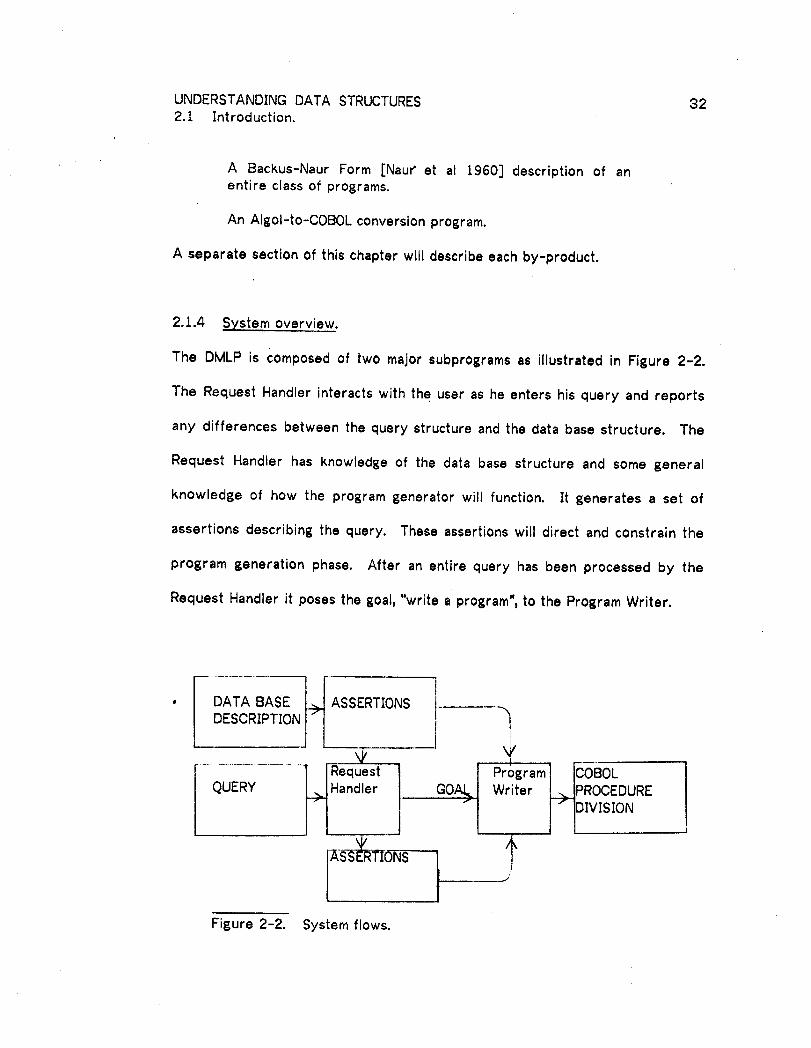
2.1.4 System overview.
The DMLP is composed of two major subprograms as illustrated in Figure 2-2.
The Request Handler interacts with the user as he enters his query and reports
any differences between the query structure and the data base structure. The
Request Handler has knowledge of the data base structure and some general
knowledse of how the program generator will function. It generates a set of
assertions describing the query. These assertions will direct and constrain the
program generation phase. After an entire query has been processed by the
Request Handler it poses the goal, "write a program", to the Program Writer.
. DATA BASE ASSERTIONS tDESCRIPTION
.f r
Handler GOA_ Writer _JPROCEDURE
. I" IDIVISI°N
Figure 2-2. System flows.
UNDERSTANDING DATA STRUCTURES 332.t Introduction.
The Program Wriler attempts to satisfy the goal posed by the Request Handler
using:
Programming techniques defined in the system.
Asserlions describing the larget data base structure.
Assertions describing lhe information retrieval query.
2. t.5 CJ!at_t_r 9..LJ[!j'2e
To aid the reader in the necessary jumping around between the sections so that
he can "hootsJrap" his understanding, an outline of the sections is presented
below. Not essential to an understanding of the system are sections 2.3, 2.9
and 2.]0.
2.1 ]nlroduclion.
Presents a chapter oLItline, a simple example and the top
level system structute.
2.2 The APG System.
Describes the logical basis of the axiomatic representation,and the program generalion method in general.
2.3 Program Generation vs a Generalized Interpreter.A juslification of the approach, is relatively independent ofthe other sections.
2.4 HI- IQ, the Query Language.Describes the primary input to the system.
2.5 Reque_,l Handler Assertions.
Describes the internal description of a query, used to directand conslrain program generation.
2.6 A BNF Description of the Generated Procedure.
Describes the system output in Backus-Naur form, useful fordiscu<_sion of the types of program constructs generated.

UNDERSIANDING DATA STRUCTURES 342. t Introduction.
2.7 Assertions.
Des(:ribes ll_e simple Boolean expressions with which morecomplex slalements of the logic can be made.
2.8 A Frame for tile Semantics of Data Structures.
Describes the rules, stated in terms of the asserlions_whereby the system "understands" data structure and Data
Manipul ation Language.
2.9 Efficiency Considerations.
Describes what was done, and not done, to insure generationof efficient programs.
2. ! 0 Algol to COBOL Conversion.
Describes translation to COBOL from an internal Algol-likerepter_entation of the completed program.
2.] Examples of Procedure Generation.

UNDERSTANDING DATA STRUCTURES 35
2.2 -fhe APG _S._,te!!L.
Program construction is carried out using a domain independent automatic
program generation system, hereafter denoted by APG, reported in [Buchanan
and Luckham 19.74; Buchanan 1974]. The APG has been extended in form as
well as conlenl for the purposes of this thesis. To sketch the ogiCal basis of
the APG, I review some elements of the logic of programs and show how time
descriptive formalism for APG (called a Frame) is formulated and used in
program [_',eneralion. Sections 2.2.1 and 2.2.2 have been condensed directly
from the original reports [Buchanan and Luckham 19741 Buchanan 1974; ]garashi,
London. and Luckham t973; Hoare 1969].
J
2.2.1 L_oFjc of Erp_F_rams.
Statements of the logic are of the form P{A}Q where P,Q are Boolean
expressions (often called assertions) and A is a program or program part.
P{A}Q means "if P is true of the input state and A halts then Q is true of the
output state".
A rule of inference is a transformation rule from the conjunction of a set of
statements (prenfises, say HI ,...,Hn ) to a statement (conclusion, ,say K). Such
rules are denoted by
H / ,...,14n
K
UNDERSTANDING f)A]A STRUCTURES 362.2 lhe APG System.
2.2.2 Frames.
The rules in a frame F: are of three kinds:
PROCEOUI_ES transform states into states and are expressed as sla|ements
in the logic of programs.
SCHEMES are methods for constructing programs and are expressed as
rules of inference in Ihe logic of programs.
RELATIONAL LAWS: definitions and axioms which hold in all states and
serve to "c:omplete" incomplete state descriptions by permitting first order
deduclion of other elements of a state from those given.
A problem for program construction may be stated as a pair <I,G>, where ] is an
input assertion (or initial state) and G is the output assertion (or goal that must
be true in the outplfl slate). The program construction task is to construct a
program A such that ]{A}r, where I'oG. A solution is the sequence of rules of F
used in the construction of the solution program A..
Notation: Substitutions, denoted by _, do not replace any variable that occurs in
the initial state ]. Expressions, all of whose variables occur in the initial state
are called "fully inslantiated". I- denotes a first order deduction using F and
the standard rules described below.
Standard rtJlet_: A ._,et of rules representing standard programming knowledge
are implemented in the program construction methods of the problem solving
UNDERSTANDING DATA STRUCTURES 372.2 The APG System.
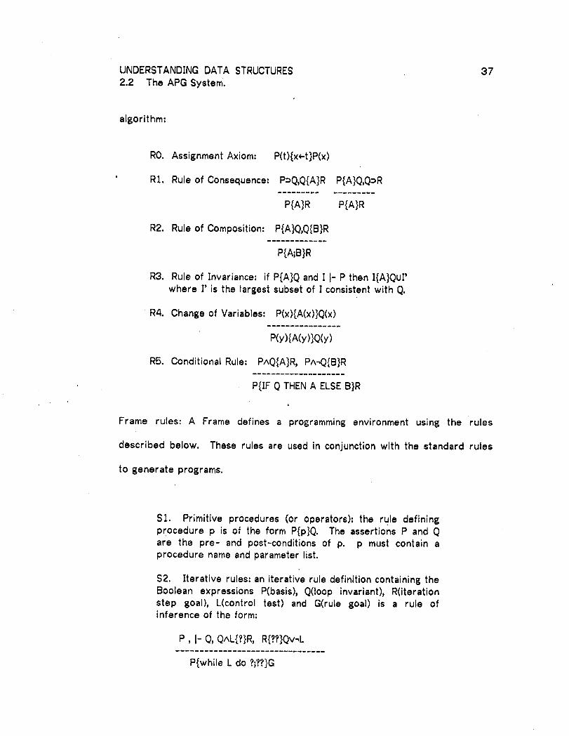
algorithm:
RO. Assignment Axiom: P(t){x<--t}P(x)
• Rt. Rule of Consequence: P=Q,Q{A}R P{A}Q,Q=R
P{A}R P{A}R
R2. Rule of Composition: P{A}Q,Q{B}R
P{A;B}R
R3. Rule of Invariance= if P{A}Q and I I- P then I{A}Qu£where l' is the largest subset of I consistent with Q.
R4. Change of Variables: P(x){A(x)}Q(x)
P(y){A(y)}Q(y)
R5. Conditional Rule: PAQ{A}R, PA_Q{B}R
P{IF Q THENA ELSE B}R
Frame rules: A Frame defines a programming environment using the rules
described below. These rules are used in conjunction with the standard rules
to generate programs.
Sl. Primitive procedures (or operators)= the rule definingprocedure p is of the form P{p}Q. The assertions P and Qare the pre- and post-conditions of p. p must contain aprocedure name and parameter list.
$2. Iterative rules: an iterative rule definition containing theBoolean expressions P(basis), Q(Ioop invariant), R(iterationstep goal), L(control test) and G(rule goal) is a rule ofinference of the form:
P, J- Q, QAL{?}R, R{??}Qv-,L
P{while L do ?;??}G

UNDERS]ANDING DATA STRUCTURES 382.2 The APG System.
$3. Definitions: A definition of G in terms of P is a logicalequivalence I- P_G.
$4. Axioms: A frame axiom P is a logical axiom I- P.
The Frame is {ornpiled by the APG to form the DMLP. Each rule in the Frame
results in a Micro-Planner lheorem. Such Micro-Planner constructs are nol
actually theorems, but that terminology will be adhered to because of historical
precedent. _.
Each compiled theorem contains premises (or a pre-condition) and conclusions
(or a post.--condition). For example, the Micro-Planner theorem corresponding to.
the'rule P{A}R has a lheorem body for the pre-condilion P and a calling pattern
for the post-condition R.
2.2.3 P!'_gj1ran! p=eneration.
The theorems are used in a recursive subgoaling procedure to generate
information retrieval programs. The recursive procedure first builds a plan for
the target program in depth-first fashion. The plan is a tree and the branches
from a node correspond to the subgoals spawned at that node. For example, if
the current goal is R, and R is not directly true in the current state, then the
system examines lhe set of theorems and selects one which has a
post-condilion, say Q, that matches the current goal, i.e. R(Ocz. for some
substitution c/. f.)c_ may not be a fully bound formula, but a complete binding
will be constructed during the generation process.

UNDERSTANDING DATA STRUCTURES 392.2 The APG Syst'em.
If the rule instance P_z{A}@.z achieves R as above, then Pal. becomes the current
8oal. if i{t]}P_cz.' (i is the current state), then by the rule of composition
]{B;A}@.._c_", and by the rule of consequence, I{B;A}R. The system finds B;A as
the proBram to achieve R from the initial state I.
The subsoalin 8 process does not usually distin6uish, except as noted below,
between the lypes (ST fhroup_h $4) of Frame rules. The result is that all rules
are scanned for a post-condition matchin8 tile current 8oal. The subsoalin 6
process c_l£e2 distinsuish between rules of type $4 and other rules in that only
$4 rules or tt_e set of assertions can be used to prove the pre-conditions of an
$4 rule. Rules of fype $3 and $4 are distinsuished from the other rules in that
they cannoL chanse the set of assertions. This is a consistent distinction.
Since only proF,.rarn sesments can effect chanses in the environment (when
executed)_ only rules describin 6 their effect should be allowed to chanse the
state description.
Rules may be specified havin 8 a pre-condition which matches an assertion in its
post-conclition. Such a rule may be recursive. If it is not recursive then it may
not be used to satisfy its own pre-condition.
With the APG, f3uchanan also introduces an interestin 6 improvement to the Iosic
of proBrams by inlroducinp_, uncertainty. The value of an assertion can be TRUE,
FALSE or UNCERTA]N. This uncertain Iosic recoBnizes that there exist

UNDERSTANDING DATA STRUCTURES 402.2 The APG System.
asserlions which can only be meaningfully tested during execution of the
6eneraled program. Use of a rule containing an un'certain assertion in its
pre-condilion will result in the generation of a conditional procedure.
Assertions (le_.,cril)e tile pre- and post- condilions.of the rules. Assertions also
describe the currenl state. The 58 different assertions used in the data base
programming enviror_ment are described in seclion 2.7.
2.2.4 APG e×lension.
Time APG constructs a program of the form P{A}Q if Q contains a complete and
specific (le_,criptio[_ of the goal. This is a correct but quite cumbersome
approach for lt_e data base retrieval programming problem because the goal
statement is quite complex. Increased complexity in the goal statement results
in increased complexity in sub-goals so that the search tree becomes quite
large.
The APG paradigm has been modified for the data base application to permit
specific:alion of most of the goal in P! That is, the goal O is the general "write a
program" and P contains the specific constraints on the information set to be
retrieved by lhe goat program. In other words, the query becomes part of the
programming environmenl.
This allows selection of specific sub-goals from the set of assertions (P) by
UNDERSTANDING DATA STRUCTURES 4I
2.2 ]-he APG System.
those rules which are specifically directed by the subgoal in question. Filtering
the goal to the appropriate rules in this manner reduces the "baggage" carried
by the sub--goaler and dramatically reduces fruitless search: On average only
/4_ of the rules tried are unne(:cessary.

UNDERSIAN[I)ING DATA STRUCTURES 42
2.3 [-_ro_E£gramGeneration vs a Generalized Interpreter.
The terms compilation, inlerprelalion and automatic program generation are
related, but I differentiate between them as follows:
C2mf2i!at!gr! - translation of an entire program from highlevel procedure to low level procedure.
_At/l_9_!na__llic_ p_J_ generation translation from arlon--procedural description of a program to procedure.
[_3!p.!Er'_1l_#ti_9_-- statement by statement translation andexe(ution of procedural commands or non-proceduraldes{riptions.
Rather lhan generating reusable procedure, interpreters generate immediate
results. In a production environment, the classical break even analysis shows
that procedure generators have a cost advantage if expected usage exceeds the
break even point (Figure 2-3).
kCOST BREAK EVEN
PER '____._
USAGE INTERPRETER
PROCEDUREGENERATOR
USAGE
Figure 2-3. Average cost per usage for generated andinterpreted programs in a production environment.

UNDERSIANDING DAIA STRUCTURES 43
2.3 Program Generation vs a Generalized Interpreter.
A break even analysis is important in the choice of selecting a vehicle for a
particular application, but in a research environment this is not the type of
choice being made. Instead, researchers should attempt to provide both so that
the choice is available to users.
Procedure generalor. _, are data free. This permits partial debugging of a system
without a data ba_._e. To do the same with an interpreter would require the
construction of a ch_ta simulator for the interpreter.
Data freeness was an important reason for building the DMLP as an automatic
programmin£_ _.ysiem. As a matter of fact, no data bases have been buill with
which to test the generated procedures. | expect that some generated
programs will probably contain errors because this type of testing has not been
done, but thic_ lhesis stands as a demonstration of how far the work could
proceed without data bases.
Other reasons for choosing the APG were:
The formalism discussed in section 2.2 - helps break downthe problem and provides a framework for discussion.
The £eneration of proF_rams as a product - provides feedbackto the ret.earcher on the operation of the DMLP and can beused to di_c:u_s results.
The second advantage is not major because the same can be accomplished with
an interpreter if it has an internal trace.

UNDERSTANDING DATA STRUCTURES 44
2.3 Program Generation vs a Generalized Interpreter.
In a precedin8 paragraph I stated that researchers should build both
interpreters and procedure _enerators so that the best method can be selected
in the production environment. My experience with the DMLP as a procedure
p:,enerator will aid in buildin 8 such an interpreter: Section 2.6 presents a BNF
description for all prosrams correspondin8 to H|-10 queries.

UNDERSTANDING DATA STRUCTURES 45
2.4 t::_.!:!Q,!he_'Q.u_rzL_n_Au#_e_.
In Chapler One ] slated lhat people tend to communicate information in
hierarchi{al, matrix or combined hierarchical-matrix format, even if we are aware
of the mullidimensionalily of the data. Usually we communicate a parti(ular
piece of information within the context of only a few relations that it may have
to olher information. This is so because speech, hearing, writing and reading
(but perhaps not vision) are essentially serial (single channel, one dimensional)
processes.
To communicate information of more than one dimension through a single
channel requires the use of markers and codes to establish dimensionality
contexts. After encountering several context changing markers in a
communication, people soon find it difficult to keep several "trains of thought"
(note the linearily implicit in this idiom) going at once.
HI--IQ (Ltlerarchical !nteraclive Ouery)language is designed for the specification
of hierarchical-matrix reports. Other design goals for FII-IQ were flexibility in
specifying hierarchical contexts, and the ability to specify the calculation of
statistics. I also wanted 1o make the system usable for people with minimal
knowledge of data base structure. This meant that the HI-IQ processor had to
understand some of the concepts discussed in Chapter 1 such as downward
attribute migration and confluent hierarchies.
UNDERSTANDING DATA STRUCTURES 46
2.4 Fll--I(), the Query Language.
Because ol the preponderance of hierarchies in report structure, statistical
calculation, and logical quantification, it seemed only natural to give HI-]Q a
hierarchical slruclure. The hierarchical query slructure is reinforced visually
for the user by further indentations of system prompts for every hierarchical
level referenced.
A HI-IQ query contains one or more hierarchical levels. Each level is used to
specify a matrix in the output report, to specify the calculation of a statistic, or
to check the lruth value of a quantified condition. A simple one level query
results in a report consi,._ting of a single matrix which contains no statistics.
SLIch a query is illuslrated in Figure 2-/.
It is not unLIsual for the definition of a particular level to be interrupted by the
definilions of lower levels. If the user desires the calculation of a particular
statistic, say an average, then the system next asks him to define the calculation
of thai average before proceeding with the further specification of the level in
which the mlerage was requested. The prompt indentation indicates to the user
which hierarchical level he is currently in.
Figure 2-4 presents a BNF description of HI-IQ. Since HI-IQ is an interactive
language, only porlions of a query are typed by the user. To distinguish such
entries from the characters typed by the system_ all system typed characlers
have been _m(Jerlined.
UNDERSTANDING DATA STRUCTURES 47
2.4 FII-I(_), lhe Query Language.
Backus-Naur Form (BNF) [Naur el al ]960] is a formalism invenled for the
• description of prograrnming languages, specifically the grammatical structure
(syntax ra|her lhan semanlics) of those programming languages. BNF can also
be used to describe non-programming languages, such as a restricted subset of
English. An excellent description and illustration of BNF can be found in
[McKeernan et al ]970].
The sequence of prompts for a particular hierarchical level always consists of
three suhsequen(es. These three subsequences are <Record name>,
<CONDITION LINES> and <ITEM LINES>.

UNDERSTANDING DATA STRUCTURES 482.4 HI-IQ, live Query Language.
<QUERY> ::= <LEVEL>
<LEVEL> ::= PRIMARYRECORDFOR(<COMMAND>)* <Record name>CONDITIONSFORRETRIEVAL<CONDTIONLINES>ITEMS OR STATS <MODIFIER><ITEM LINES>
<CONDITION LINES> ::= * NIL I<CONDITIONLINE> <CONDITIONLINES>
<CONDIIION LINE> ::= *_ORI'ALL <LEVEL>J*ANY <LEVEL>J*_<TEST>n
<TEST> ::= (<lOt> <REL><]OCR>)I(<IOC> <REL><STAT>) <LEVEL> I(<STAT> <REL><IOCR>) <LEVEL> J(<STAT> <REL><STAT>) <LEVEL> <LEVEL>
<IOCR::" ::= RUN-riMEI <IOC>
<10C> ::= <Item name> I <Constant>
<REL> ::= LE I LT I GEI GT I EQ I NE
<ITEM LINES> ::--- *_NILI<ITEM LINE> <ITEM LINES>
<ITEM LINE:" :;= _<IOC>I *_STAT> <LEVEL>I*_REPEAT<LEVEL>I*ONE <LEVEL> I*COND <TEST>
<COMMAND:> :i= MAIN I ALL I ANY IREPEATI ONEI <STAT>
<STA1> ::--- COUNT I TOT lAVE JMINIMAX
<MODIFIER._. ::= TO BE DISPLAYEDJFOR AVE ]FORTOT I FORMIN I FORMAX
Figure 2--4. BNF for the HI-IO language.(System prompts are underlined.)

UNDERSTANDING DATA STRUCTURES 49
2.4 H[-IQ, the Query Language.
2.4.1 <Record name> subsequence.
The <Record name> subsequence consisls of a single system prompt and user
reply wherein the user must name the context record for the current
hierarchical level. It is possible to have time system determine the context
record for a particular level from the other two prompt subsequences. This
would furlher reduce the knowledge that the user must have to use the system,
but it would also increase lhe possibility of undetected errors because of the
loss of redunclancy.
2.4.2 <CONDII ION LINES> subsequence.
The ,:CONDITION LINES> sub-sequence of prompts in a query level is of
indefinile leng|h. This prompt sequence defines the condition that must be true
to retrieve the context record. The condition is specified using the logical
connectives AN[) and OR and a set of tests in a disjunctive form. That is to say,
if A, B, C, and D are all tests, AABvCAD is equivalent to (AAB)v(CAD). However,
the latter',.;pecification is not allowed; the user cannot control the bindings of
the logical connectives, AND and OR. This is not a major restriction. Any
condition can be specified in disjunctive form, albeit in a cumbersome way.
Because of the immediate binding of AND, it is the default connector and need
not be specified by the user.
Particular tests are of the form (A REL B). REL can have one of six values: E0,
NE, LT, LE, GT, GE. "A" can be an item name, a statistic, or a numeric or

UNDERSTANDING DATA STRUCTURES 50
2.4 HI-IE,), the Query Language. '
non-numeric lileral. "B" can be any of these; in addition "B" carl be the
keyword RUN]IME. The use of RUNTlMEsignals that the generated program will
be an interacfive program. If execution of the generated program becomes
dependent on an actual value for "B", it (the generated program) will prompt the
user wilh "A REL?", and the user's reply will be used to determine the truth
value of (A REL B).
Universal or exi£tential quantification can be specified as part of a condition.
Since quantification is only meaningful over a set of possible values, the user
must be ready to define a new hierarchical level for every quantifier, specified.
After encountering either of the quantifiers ALL or ANY, the system
automatically proceeds to prompting for the definition of a new hierarchical
level.
The syslem also proceeds to a new hierai'chical level whenever the user
specifies a statistic so that the calculation of the statistic can be defined. A
statistic is specified with one of the following keywords ' COUNT, TOT, AVE, MIN,
and MAX.
i

UNDERSTANDING DATA STRUCTURES 51
2.4 HI-IQ, the Query Language.
CONDITIONSFO_._RRRETRIEVAL*(PATNO EQRUNTIME),(PATAGE LT 25)*NIL
CONDITIONS FOR RETRIEVAL*_(SALARYLT 6000)*OR*.(SALARYLT IO000)*ANY
PRIMARY RECOR_DD,[DEPENDENTCONDITONSFORRETRIEVAL
*_.(AGELT 2 I)*NIL
*NIL
Figure 2-5. Two examples of retrieval conditions.
Figure 2-5 illustrates two retrieval conditions. The first is a simple conjunction
of two tests. The .second condition indicates that a record (employee) should be
retrieved it the employee has a salary below $6,000, or if he has a salary below
&lO,O00 and at least one dependent child.
2.4.3 <]TEM LINES> subsequence.
The <ITEM LINFS> subsequence is also of indefinite length and is used to define
the matrix as'.,ociated wilh the current hierarchical level. This matrix is either
an output malrix (for the report) or a statistical matrix, depending on the
command which invoked the current hierarchical level. The system calculates
UNDERSTANDING DATA STRUCTURES ._52
2.4 Nl-10, the Query Lan6uage.
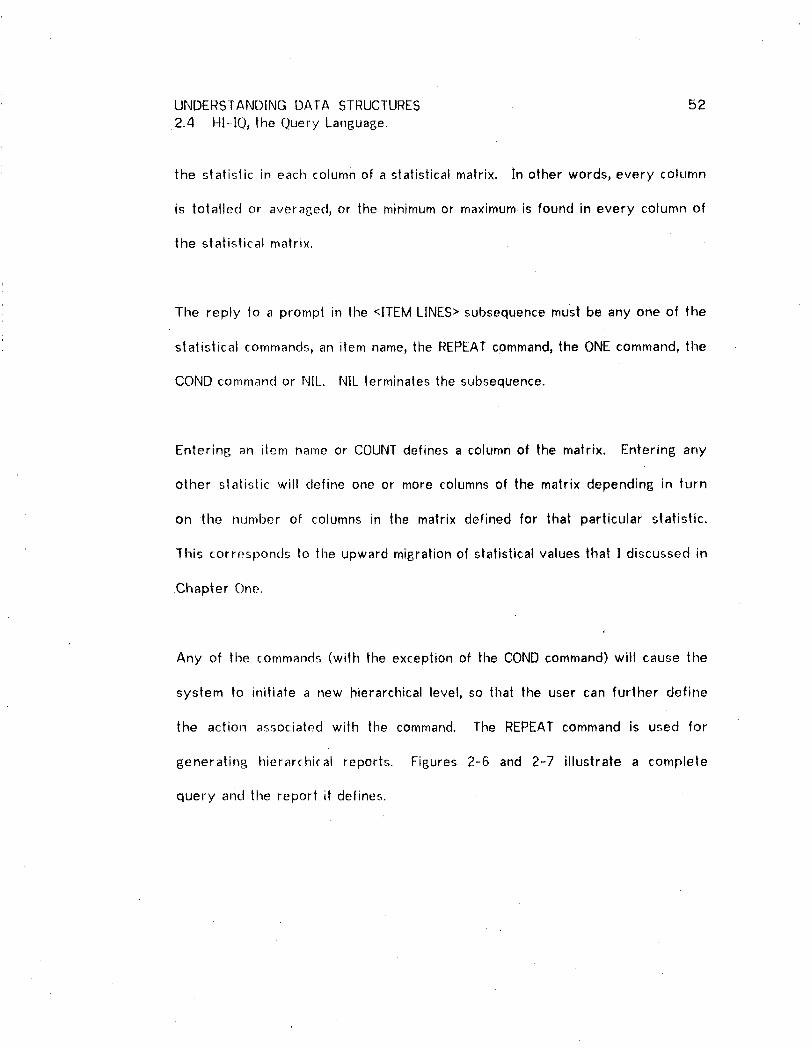
the statistic in each column of astatistical matrix. In other words, every column
is totalled or averased, or the minimum or maximum is found in every column of
the statistical matrix.
The reply to a prompt in the <ITEM LINES> subsequence must be any one of the
statistical commands, an item name, the REPEAT command, the ONE command, the
COND command or NIL. NIL terminates the subsequence.
Enterin 6 an ilem name or COUNT defines a column of the matrix. En|ering any
other stalislic will define one or more columns of the matrix depending in turn
on the number of columns in the matrix defined for that particular statistic.
This corresponds to the upward migration of statistical values that I discussed in
Chapter One.
Any of the commands (with the exception of the COND command) will cause the
system to initiate a new hierarchical level, so that the user can further define
the action associated with the command. The REPEAT command is used for
generatin£ hierarchical reports. Fissures 2-6 and 2-7 illustrate a complete
query and tile report it defines.

UNDERSTANDING DATA STRUCTURES 532.4 HI--IQ, the Query Language.
PRIMARY RECORD/MAIN)_DOCTORCONDITIONSFORRETRIEVAL*NILITEMS OR STATS TO BE DISPLAYED_DOCNAME
_DOCAGE,_SPECIALTY_REPEAT
PRIMARYRECORD{REPEAT).:_PATiENTCONDITIONSFORRETRIEVAL
*__(PATAGEGT 2]):_.NILITEMS OR STATS TO BE DISPLAYED_PATNAME*PATAGE
*DIAGNOSIS*NIL
*NIL
Figure 2-6. Query (PI) for the report of Figure 2-7.

UNDERSTANDING DAIA STRUCTURES 542.4 HI-IQ_ lhe QIJery Language.
FREDERICKS 41 G.P.SMITH 48 BOTULISMJONES 22 APPENDICITIS
BROWN 36 INTERNISTSMITt4 48 BOTULISM
SLENDER 52 GENSURGERYJONES 22 APPENDICITIS
BLUE 49 GYNECOLOGYWILLIAMSON 31 MISCARRIAGE
Fi6ure 2-7. A hierarchical-matrix report.
The top level matrix of this report contains three columns for DOCNAME,
DOCAGE anct SPECIALTY. The secondary matrix, hierarchically nested in the top
level matrix, also contains three columns, PATNAME,PATAGE and DIAGNOS]S.
Note that in Figure 2-6, the prompt sequence for both levels of the report
included all three sub-sequences as defined earlier. This query specifies a
condition in the second level (on the retrieval of patients). This condition will
not affect the retrieval of DOCTORrecords or any other records not within the
context of the PATIENT record. The condition (PATAGE GT 21) applies only to
this particular context of the PATIENT record. The PATIENT record could have
been referenced elsewhere in the query, and the condition (PATAGE GT 21)
would not have applied.

UNDERSTANDING DATA STRUCTURES 55
2.4 HI-IQ, the Query l_anguage.
The function of the ONE command is very similar to the REPEAT command except
that only the first line of the matrix at the next level will be retrieved and
displayed in the report. If tile REPEAT command in Figure 2-6 is replaced with
a ONE command, then the resulting report would resemble Figure 2-7 with the
exception of the third line (which would not be included).
The user carl control the appearance of particular attribute values on a
particular line wilh the conditional output (COND) command. It is especially
useful for exception reporting. Subsequent to encountering the CONDcommand,
the system responds as if a new hierarchical level had been specified, except
that the first prompt sub-sequence is skipped. The first sub-sequence is not
necessary b.ecause COND cannot change the record context.
There are a few other cases in which the full prompting sequence is not
applicable, and other prompting sub-sequences wilt occasionally be suppressed.
The third sub-sequence is not entered for the COUNT command because
counting applies only to line occurrences of a matrix, the columns of the matrix
do not affect it.
Similarly, it does riot rnake sense to specify a matrix within the context of a
condition quantifier (ALL or ANY), so again the third prompt sub-sequence is not
entered by the system.
UNDERSTANDING DATA STRUCTURES 562.4 HI-IQ, the Query Language.
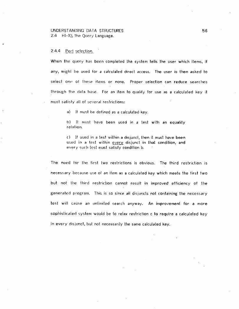
2.4.4 Port selection.
When the query has been completed the system tells the user which items, if
any, might be used for a calculated direct access. The user is then asked to
select one of these items or none. Proper selection can reduce searches
through the data base. For an item to qualify for use as a calculated key it
must satisfy all of several restrictions:
a) It must be defined as a calculated key.
b) It must have been used in a test with an equalityrelation.
c) If used in a test within a disjunct, then it must have beenused in a test within eve_z_eLy- disjunct in that condition, andevery such lest must satisfy condition b.
The need for the first two restrictions is obvious. The third restriction is
necessary because use of an item as a calculated key which meets the first two
but not the third restriction cannot result in improved efficiency of the
generated program. This is so since all disjuncts not containing the necessary
test will cause an unlimiled search anyway. An improvement for a more
sophistica|ed system would be to relax restriction c to require a calculated key
in every disjunct, but not necessarily the same calculated key.

UNDERSTANDING DATA STRUCTURES 57
2.5 Requ_4,t Handler Assertions.
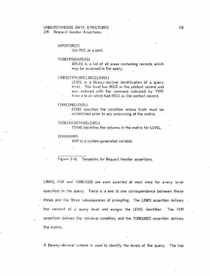
The Request Handler describes the querywith aset of assertions. An assertion
must conform to one of the templates in Figure 2-8.
There will be at most one [SPORT assertion for a particular query. This is
asserted only if REC satisfies all criteria listed in section 2.4.4, and if it has been
selected by the user for use as a calculated key.
There is exactly one TOBEOPND assertion per query. The AREAS list indicates
which areas of the data base contain records that will be accessed during the
processing associated with the query. Delerminalion of the AREAS list is not
simply accomplished by tallying the names of the areas that contain the records
referenced in the query, it is possible that the generated program will access
areas not directly referenced via record names in time query. This situation
occurs if an access path between two records passes through an intermediate
record. DeterrninMion of tile AREAS list therefore involves a determination of
all access paths.
UNDERSTANDING DATA STRUCTURES 582.5 Request Handler Assertions.
ISPO[_T(REC)
Use REC as a port.
TOBEOPND(AREAS)
AREAS is a list of all areas containing records whichmay be accessed in the query.
LINKS(TYPE,REC !,REC2,LEVEL)LEVEL is a Dewey-decimal identification of a querylevel. This level has REC2 as the context record and
was erHerecl with the command indicated by TYPEfrom a level which had RECI as the context record.
FOR(COND,LEVEL)COND specifies the condition whose truth must be
established prior to any processing of the matrix.
TOBELJSED(ITEMS,LEVEL)HEMS identifies the columns in the matrix for LEVEL.
t
ISVAt_(VAR)
VAR is a system generated variable.
FiBure 2-8. Templates for Request Handler assertions.
LINKS, FOR and TOBEUSED are each asserled at most once for every level
specified ir._ the query. There is a one to one correspondence between these
three and the three subsequences of prompting. The LINKS assertion defines
the context of a query level and assigns the LEVEL identifier. The FOR
assertion defines the retrieval condition, and the TOBEUSED assertion defines
the matrix.
A Dewey-decimal scheme is used to identify the levels of the query. The top

_JNDERSTANDINGDATA STRUCTURES 592.5 Request Handler Assertions.
level is indentified as X. The first level occuring within the context of the top
level is identified as X.1. X.2.1 identifies the first hierarchy in the second
hierarchy occuring within the top level of the query.
2.5.1 LINKS assertion.
The TYPE parameter of LINKS is actually a list containing two sub-parameters.
Values of the first sub-parameter are limited to the names given in Figure 2-9.
With the exception of MAIN, these are all commandswhich invoke new query
levels. MAIN is used to identify the top level of the query and has the same
interpretation as the REPEATcommand.
The second TYPE sub-parameter is a unique system-created variable name.
This variable is used for counting record occurences if the first sub-parameter
is COUNT or AVE, or for controlling quantification if the first sub-parameter is
ONE, ALL or ANY. Although TYPE will always contain a variable name as its
.second parameter, this variable is only used by the Program Writer if the first
parameter in TYPE is one of the five commandsindicated above.
MAIN ALL TOTREPEAT ANY AVEONE COUNT MIN
MAX
Figure 2-9. Possible values of the TYPE parameter in LINKS.
UNDERSiANDING DATA STRUCTURES 602.5 Request Handler Assertions.
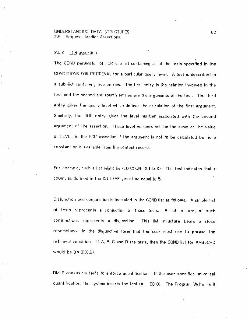
2.5.2 FOR asr,erlion.
The CON[) parameter of FOR is a list containing all of the tests specified in the
CONDITIONS FOR REIRIEVAL for a particular query level. A test is described in
a sub-list containing five entries. The first entry is the relation involved in the
test and the second and fourth entries are the arguments of the test. The third
entry gives ihe query level which defines the calculation of the first argument.
Similarly, lhe fifth entry gives the level number associated with the second
argument of the assertion. These level numbers will be the same as the value
of LEVEl_ in Ihe FOR assertion if the argument is not to be calculated bul is a
constant or is available from the context record.
For example, such a list might be (EQ COUNT X./ 5 X). This lest indicates that a
count, as defined in the X.I LEVEL, must be equal to 5.
Disjunction and conjunction is indicated in the CONDlist as follows. Asimple list
of tesls represents a conjuction of those tests. A list in turn, of such
conjunctions represents a disjunction. l'his list structure bears a close
resemblance to the disjunctive form that the user must use to phrase the
retrieval condilion. If A, B, C and D are tests, then the COND list for AABvCAD
would be ((A,B)(C,D).
DMLP constructs tests to enforce quantification. [f the user specifies universal
quantification, the system inserts the lest (ALL EQ 0). The Program Writer will

UNDERSTANDING DATA STRUCTURES 61
2.5 Requesl Handler Assertions.
eventually construct the program so that a variable associated with ALL (defined
in the TYPE parameter of the LINKS assertion)is set to non-zero if the
associated condition is ever false, qhis variable, also called aquantification flag,
signals the truth value of the entire condition.
Similarly, specifyin 8 existential quantification results in a test (ANY EQ l). The
variable associated with ANY is set to non-zero in the generated procedure if
the associated condilion is ever lrue.
2.5.3 TOBEUSED assertion.
TOBEUSED describes the matrix associated with a query LEVEL. The I1EMS
parameter is again a list, each entry describing a column of the matrix. The
entry describin 8 a column is in turn also a list consisting of three entries. The
first of these is an item name, slalistic command, or constant, The second entry
indicates the query level where the calculation of the entries in the column is
defined. The third entry assigns a variable name which can be used by the
system for the calculation of a statistic.
As an illustration, Figure 2-10 gives the complete set of assertions derived by
the Request Handler from the query of Figure 2-6. It is these assertions along
with assertions describing tile data base, that the Program Writer will use to
generate the desired procedure.

UNDERSTANDING DATA STRUCTURES 622.5 Request Handler Assertions.
[OBEOPND ((A] A2)) "L_INKS((MAIN) PORTDOCTORX)LINKS ((REPEAI X4) DOCTORPATIENT (X . 1))FOF_ ((((GT PATAGE (X . 1) (21) (X . l)))) (X . l))TOP,ELISED (((DOCNAMEX Xl) (DOCAGEX X2) (SPECIALTY X X3)
(REPEAT (X . [) X10)) X)1-Of_EIi]SED (((PATNAME (X . t) X5) (PATAGE (X . 1) X6)
(DIAGNOSIS (X . J)X7)) (X. ])))ISVAR (XtO)ISVAR (X7)ISVAR (X6)ISVA_ (X5)ISVAF_(X4)ISVAR (X3)ISVAR (X2)ISVAR (Xt )
Fisure 2-10. Assertions describin6 the query of Fisure 2-6.
UNDERSTANDING DATA STRUCTURES 63
2.6 A BNF Descrij2t_io__D_nof the Generated Procedure.
The Frame de_,cribed in section 2.8, defines the set of programs semantically an___dd
permits a derivation of the correct syntax. This would seem to make a BNF
description superfluous. However, knowing something about the general syntax
of the generated programs will make the Frame easier to understand.
BNF is LJsually used to describe a computer language. It is possible to generate
a BNF description of COBOL as augmented by the Data Manipulation Language
and this [:_NFdes_:ription would include all the programs i_enerated by. the DMLP.
Tile BNF de._cription in Figure 2-It is more restricted and describes only a
subset of all programs that can be written in COBOL. But it still encompasses
all programs that will be generated by the DMLP.
The BNF of Figure 2-1 t uses the convention that lower case strings enclosed in
< > are terminal symbols. ]his convention i_; used for symbols which stand for
COBOL or [)MS names or lilerals. These names or literals must abide by the
COBOL and DMS rules.

UNDERSTANDING DATA STRUCTURES 642.6 A BNF Description of the Generated Procedure.
<PROGRAM" ::= PROCEDUREDIVISION.<MAIN SECTION> I<PROGRAM><SUB SECTION>
<MAIN SECTION> ::= PROCI SECTION.<MAIN PARAGRAPH>I<MAIN SECTION><SUB PARAGRAPH>
<SUB SECTION> ::= <SECTIONNAME>SECTION.<SUB PARAGRAPH> I<SUB SECTION><SUB PARAGRAPH>
<MAIN PARAGRAPH> ':= <PARAGRAPHNAME>.<OPEN><PORT><CLOSE>STOP.
<SUB PARAGRAPH> ::= <LOOPBODY> I <ACTIONPARAGRAPH>i<INTERACTIVEPARAGRAPH>
<OPEN> ::= OPENAREA <AREA LIST>.
<CLOSE> ::= CLOSEAREA <AREA LIST>.
<AREA LIST> ::= <Area name> I <AREA LIST> <Area name>
<PORT'> ::= <FIND><ACTION> I<LOOP CONTROL>
<FIND> ::= <INITCALCKEY> FIND <Portrecord>RECORD•
<INITCALCKf_Y> ::= MOVE <HAS VALUE> TO <Calckey>.IDISPLAY "<Calckey>....EQ_"ACCEPT <Calckey>.
<LOOP CONTROL> ::= FIND FIRST<Recordname> RECORDOF <LOOP CONTEXT>.
MOVE CURRENCY STATUS FOR <LOOP CONTEXT>
TO <Record data base key>.PERFORM<LOC)PPARAGRAPHNAME>
UNTIL <CONTROLTEST>.
<LOOPCONTEXT> ":= <Set name> SET I <Area name> AREA
<CONTROLTEST> ::= ERRORSTATUSIS NOT EQUALTO 0 I(ERRORSTATUSIS NOT EQUALTO O)
OR(<SYSTEMTEST>)
Figure 2-I 1 is continued on lhe next page.

UNDERSTANDING DATA STRUCTURES 652.6 A BNF Description of tile Generated Procedure.
<LOOP BODY> ::= <LOOPPARAGRAPHNAME>.MOVE CURRENCYSTATUS FOR<LOOPCONTEXT>
TO <VARIABLE NAME>.<ACTION>MOVE <VARIABLENAME> TO <Record data base key>.FIND <Record name> USING<Record data base key>.FIND NEXT <Record name> RECORD
OF <LOOPCONTEXT>.
<ACTION PARAGRAPH> ::= <ACTION PARAGRAPH NAME>. <ACTION>
<ACTION> ::= <DISPLAYSEQUENCE> I<STATISTIC SEQUENCE> I
<CONDITIONTEST> i<SET Q FLAG> I<SET Q FLAG> <CONDITIONTEST> I<DISPLAYSEQUENCE> <SET Q FLAG> I<FINDOWNER SEQUENCE> <ACTION>
<DISPLAY SEQUENCE> ::= <DISPLAY>I<VALUE DETERMINATIONS> <DISPLAY><DISPLAYSEQUENCE> <CONDITION TEST> I<DISPLAYSEQUENCE> <LOOP CONTROL>
<DISPLAY> ::= DISPLAY <DISPLAY LIST>.
<DISPLAY I.IST'* ::= <HAS VALUE> I<DISPLAY LIST><HAS VALUE>
<STATISTIC SEQUENCE>::= <CALCULATION> I
<VALUE DETERMINATION> <CALCULATION> I<STATISTICSEQUENCE> <CALCULATION> I<STA]ISTICSEQUENCE> <VALUE DETERMINATION>
<CALCULATION>
<CALCULATION> ::= MOVE <COUNT VARIABLE NAME> +I
TO <COUNT VARIABLE NAME>. IMOVE <TOTAL VARIABLE NAME> + <ITEM OR VAR>
TO <TOTAL VARIABLE NAME>, IMOVE <MIN OR MAX> OF <STATISTICVARIABLE NAME>
AND <ITEM OR VAR> TO<STATISTICVARIABLE NAME>
<MIN OR MAX> ::= MINIMUM I MAXIMUM
<SET Q FLAG> ::= MOVE <ZERO OR ONE> TO <QUANTIFICATION FLAG>.
Figure 2-1 1 is conlinued on the next page.

UNDERSTANDING DATA STRUCTURES 662.6 A BNF Description of the Generaled Procedure.
<CONDITION TEST> ::= <IF> I <CONDITIONVALUES> <IF>
<IF> ::= IF <TEST><CONTINUATION>ELSEPERFORM<ACTION PARAGRAPH NAME>.
<CONTINUATION> ::= NEXT SENTENCEIPERFORM<ACTIONPARAGRAPHNAME>
<VALUE DE-IERMINATIONS>
::= <VALUEDETERMINATION>I<VALUEDETERMINATIONS><VALUE DETERMINATION>
<VALUE DETERMINATION>
::= <STATISTICCALC> I<GET> I<FINDOWNER SEQUENCE> <GET> I<RUNTIME>
<STATISTIC CALC> ::= <STAT INIT><LOOP CONTROL> I<STAT INIT><STAT INIT><LOOP CONTROL>MOVE <TOTAL VARIABLE NAME>
DIVIDEDBY <COUNT VARIABLE NAME>TO <AVE VARIABLE NAME>.'
<STAT INIT> ::= MOVE 0 TO <STATISTICVARIABLE NAME>.
<GET> ::= GET <Recordham.e>RECORD.
<FINDOWNER SEQUENCE>::= FIND OWNERRECORDOF <Set name> SET. I
<FINDOWNERSEQUENCE>FIND OWNERRECORDOF <Set name> SET.
<RUNTIME> ::= IF <Item name:, IS NOT EQUALTO HGt4-VALUES NEXT SENTENCEELSE PERFORM<INTERACTIVE PARAGRAPH NAME>.
<INTERAC[ IVE PARAGRAPH>::= <INTERACTIVE PARAGRAPHNAME>.
DISPt.AY "<Item name>.... <REL>?".ACCEPT <Item name>.
Figure 2-1 I is continued on |he next page.

4
UNDERSTANDING DATA STRUCTURES 672.6 A BNF Description of the Generated Procedure.
<CONDITION VALUES> ::= <CONDITIONVALUE> i<CONDITIONVALUE><CONDITIONVALUE>
<CONDITION VALLIE> ::= <FIND>I<QUANTIFICATION>i<VALUE DETERMINATION>
<QUANTIFICATION> ::= MOVE 0 TO <QUANTIFICATIONFLAG>.<LOOP CONTROL>
<HAS VALUE> ::= <ITEM,VAR OR NUM> i<Non-numericliteral>
<ITEM, VAR OR NUM> ::= <ITEM OR VARy I <Numeric literal>
<ITEM OR VAR> ::= <Item name> I <VARIABLE NAME>
<TEST> ::= ERRORSTATUSIS NOT EQUALTO 0 I<USER'SNEGATEDTEST> I<SYSTEMTESI>
< USERS NEGATED TES'[> ::= <HAS VALUE><RELATION><FtASVALUE>
<SYSTEM -[EST> ::= <STATISTIC VARIABLE NAME> <RELATION><ITEM, VAR OR NUM> I
<QUANTIFICATIONFLAG> <RELATION><ZEROOR ONE>
<RELATION> ::= IS EQUALTO I IS NOT EQUALTO IIS LESS THAN I IS NOT LESS THAN tIS GREATERTHAN I IS NOT GREATERTHAN
<REL> ::= EQINE IGTILT IGEILE
<ZERO OR ONE> ::= 0 I I
<SECTION NAME> ::= PROC<lnleger>
<PARAGRAPI4NAME> ::= PARA-<lnleBer>
<LOOP PARAGRAPHNAME> ::= <PARAGRAPHNAME>
<ACTION PARAGRAPHNAME>::= <PARAGRAPHNAME>
<INTERACTIVE PARAGRAPHNAME> :..=<PARAGRAPHNAME>
FiBure 2-I I is continued on the next paBe.
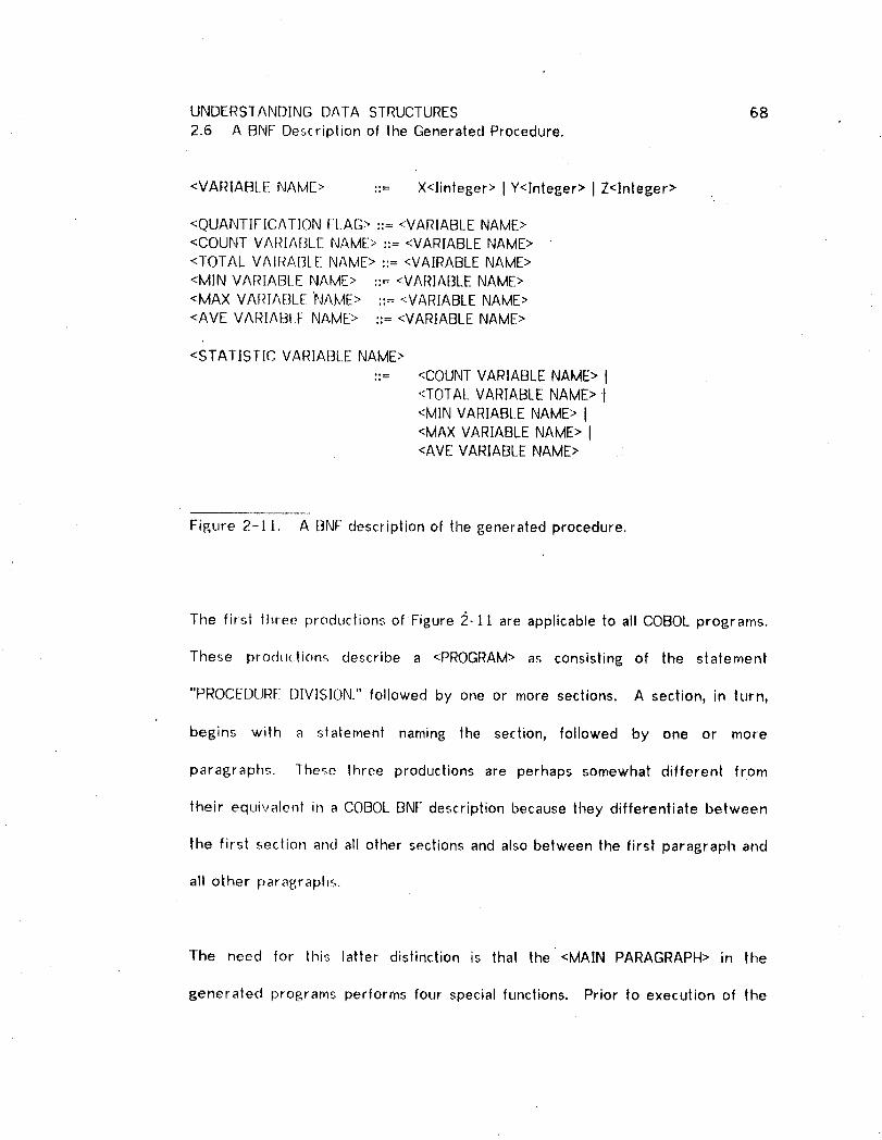
UNDERSTANDING DATA STRUCTURES 682.6 A BNF Description of the Generated Procedure.
<VARIABLE NAME> :'= X<linteger> I Y<lnteger> I Z<Integer>
<QUANTIFICATION FI.AG> ::= <VARIABLENAME><COUNT VARIABLE NAME>::= <VARIABLENAME><TOTAL VAIRABLE NAME>::= <VAIRABLENAME><MIN VARIABLE NAME> ::= <VARIABLENAME><MAX VARIABLE 'NAME> ::---<VARIABLE NAME><AVE VARIABLE NAME> ::= <VARIABLE NAME>
<STATIS[IC VARIABLE NAME>
::= <COUNT VARIABLE NAME> I':TOTALVARIABLE NAME> I<MIN VARIABt_ENAME> I<MAX VARIABLE NAME> I<AVE VARIABLE NAME> ..
Figure 2-11. A BNF description of the generated procedure.
The first three productions of Figure 2-11 are applicable to all COBOL programs.
These pro(hKlions describe a <PROGRAM> as consisting of the statement
"PROCEDUR[-!DIVISION." followed by one or more sections. A section, in turn,
begins with a statement naming the section, followed by one or more
paragraphs. These Ihree productions are perhaps somewhat different from
their equivalent in a COBOLBNF description because they differentiate between
the first section and all other sections and also between the first paragraph and
all other paragraphs.
The need for lhis latter distinction is that the <MAIN PARAGRAPH> in the
generated programs performs four special functions. Prior to execution of the
UNDERSTANDING DATA STRUCTURES 69
2.6 A BNF Description of the Generated Procedure.
rest of the program it opens all necessary areas and enters the data base. At
the end of execution it closes all areas opened at the beginning and stops
execution.
All paragraphs other than the <MAIN PARAGRAPH> are one of three types. The
first type is a paragraph that can be repetitively performed. The other two are
generated for conditional execution.
Entry into the data base is done with adata base "port". Aport can be a direct
access record using a calculated key value, a special type of set, or a search of
an entire area containing lhe port record. When a calculated key is used, then
the <FIND> and <iNir CALCKEY> productions are used. Note the possibility of
generating an inleraclive program in the <]NIT CALCKEY> production.
If a calculated key cannot be used, the program will be constructed to contain
an initial loop which either searches an area or a special type of set, known as a
system set, In either case, the constructs used are described by the <LOOP
CONTROl._> and <LOOP BODY> productions. Note here that the <LOOP CONTEXT>
production describes the differentalion between loops searching a set vs those
searching an area ....
The <LOOP CONTROL> and <LOOP BODY> productions are two of time most
important in tile BNF description. <LOOP BODY> describes the construction of
UNDERSTANDING DATA STRUCTURES 70
2.6 A BNF Description of the Generated Procedure.
the paragraph that is performed by the program section described with <LOOP
CONTROL>. For every <LOOP CONTROL> there will be a unique <LOOP BODY:,.
This restriclion cannot be indicated with the BNF because COBOL uses labels to
control execulion of program blocks. If retrieval programs were generated in a
Algol-like lansua_e (using nesling of program blocks to control program flow)
then the connection between <LOOP CONTROL> and <LOOP BODY> could be more
strongly described in the BNF. I have distinguished between LOOP, ACTION, and
INTERACTIVE paragraph names in the BNF to indicated these program flow
connections. This difference and others between Algol and COBOL is the
subject of section 2.tO.
<LOOP CONTROL> and <LOOP BODY> control the code generation for every
traversal from a section of code for a query level to a section of code for a
lower level. The <LOOP CONTROL> and <LOOP BODY> productions correspond to
the code generated for a LINKS assertion.
The <ACTION> production describes the procedure for performing the activities
within a query level. These activities include matrix display, statistical
calculation, quantification, and other condition testing. The action associated
with quantification is lhe selling of the quantification flag which determines the
truth of the quantification.
Another importanl production is the <ACTION> production. <ACTION> can occur

UNDERSTANDING DATA STRUCTURES 712.6 A BNF Description of tile Generated Procedure.
in a <LOOP BODY>, following a <FIND> in <PORT>, or within an <ACTION
PARAGRAPIt>. The code generated by <LOOP BODY> and <FIND> insures that
certain records are available so that the activity can be performed. Similarly,
the code generated by an <IF> production will test to see if the activity should
be performed.
Since the <:IF> construct is part of the <CONDITION TEST> production which in
turn can be an <ACTION>, it is possible for code to be constructed which
consists of an IF statement referencinp_ a paragraph containing another IF,
referencin_ a second paragraph containing a third IF,and so on. This is exactly
the program construction that results for every conjunction of tests in a query
condition. Section 2.9 explains the reason for the use of this programming style
rather than one which simply reproduces the entire condition in a single IF
statement.
The recursive nalure of lhe prograrn construction process becomes obvious
when we observe that any <ACTION> can involve one or more <VALUE
DETERMINATION>. <VALUE DETERMINATION> can be done with a <STATISTIC
CALC> wMch will in turn evoke a new <LOOP CONTROL>. The general purpose
of the <VALUE DETERMINATION> and <CONDITION VALUE> constructs is to
generate code thal will determine the values of the arguments needed by the
function invoked by <ACTION>. <VALUE DETERMINATION> or <CONDITION
VALUE> precede the actual display, calculation, or test processes.

UNDERSTANDING DATA STRUCTURES 722.6 A BNI: Description of lhe Generaled Procedure.
PROC/ SECTION.
IF SAt ARY IS NOT LESSTHAN 6000PERFORMPARA-201ELSE PERFORM...
PROC2 SECTION.PARA-20 ].
IF' SALARY IS NOT LESS THAN 10000 NEXTSENTENCEEI_SEPERFORMPARA-202.
PARA_202.MOVE 0 I-0 X/.FIN[) FIRST DEPENDENTRECORDOF DEPSETSET.MOVE CURRENCYSTATUS FORDEPSETSET TO DEPKEY.P[:RFO[_MPARA-203 UNTIL (ERRORSTATUStS NOT EQUALTO O)
OR (XI IS EQUALTO 1).IF X! IS NOT EQUALTO I NEXTSENTENCE
ELSE PERFORMPARA-204.
PARA-204.
pro[sr am conlinuation...
PARA 203.MOVE CURRENCYSTATUS FORDEPSETTO Yr.GET DEPEND[-NI.IF AGE[IS NOT LESS THAN 21 NEXTSENTENCE
El SE PERFORMPARA-205.MOVE Y] IO DEPKEY.FIND DEPENDENTUSINGDEPKEY.FIND NEXT DEPENDENTRECORDOF DEPSETSET.
PARA-205.MOVE ] TO X].
Figure 2-12. Code generated for the condition of Figure 2-5,
Figure 2-12 illustrates the procedure that is generated for the test, "salary less

UNDERSTANDING DATA STRUCTURES 732.6 A BNF Description of the Generated Procedure.
than $6,O00 or salary less than St0,000 and any dependent under age 2t." (The
FII-IQ equivalent is illustrated in Figure 2-5.)
PROCI in Figure 2-12 tests "salary less than $6000." If this is true then the
appropriate procedure is executed. If not true, then PARA-201 is performed.
PARA-20! checks the firsl test in the conjunction "salary less than 8]0,000 and
the existence of any dependent child." This section of code is therefore
executed only if salary is not less than 86000, in Other words, only if the first
disjunct of the condition fails. Code for secondary disjunc|s is always located in
a separate section of the Procedure Division.
PARA-20! is a simple <CONDITION TEST> containing an <IF> with no preceding
value delerminations. Since this paragraph will be executed within the scope of
a PERFORM, NEXT SENTENCE will not. cause execution of the succeeding
paragraph.
PARA-202 is also a <CONDITION TEST>_ but this lime the <IF> is preceded by a
<CONDITION VALUES> construct. In this case the <CONDITION VALUE> is a
quantification so the first statement of the paragraph is a MOVE to initialize XI,
the quantification flag. The remainder of the paragraph_ preceding the IF
statement, is a <'LOOP CONTROL>. The <CONTROL TEST> for the loop contains a
<SYSTEM TES-[>.

UNDERSTANDING DATA S]RUC1URES 742.6 A BNF Description of the Generated Procedure.
PARA-203 is a <LOOP BODY> and the <ACTION> it contains is another
<CONDTION lEST>. Y1 is used to store the data base key and a direct FIND is
done with that clata base key. The FIND using the data base key is done to
recover the proper data base context in case intervening processing has also
accessed the DEPSET set. ]t turns out that this precaution is not necessary for
this particular program, but making inclusion of the precaution dependent on
necessity would involve considerable backtracking during the program
generation process.
PARA--205 is another <ACTION PARAGRAPt4> consisting of a single <SET Q
FLAG>. Upon entry to PARA-204 the entire condition is true, and PARA-204
continues with the processing specified at that level.
This lerminates the example. Some additional comments regarding the BNF of
Figure 2-]1 are in order:
a) ]he principle of downward attribute migration isrefle(led in the <FINDOWNER SEQUENCE> as used in <VALUEDE1E}_M]NATION>.
b) The <RUNTIME> AND <INTERACTIVE PARAGRAPH>productions generate code for the interactive determination
of parameler values. Note that for "ordinary" interactivevalue determination, the interaction occurs only once duringprogram execution (because after being executed once, theparameter will not have HIGH-VALUES). Interaction 1o
determine the value of a calculated key as indicated in <]NITCAICKEY>, will occur every time another direct access isdesired.
c) The laller portion of the righl hand side of <STATISTIC
CALC > reflects lhe fact that an average is actually thequolient of lwo other statistics.
UNDERSTANDING DA[,_ STRUCTURES 75
2.6 A BNF Description of the Generated Procedure.
d) lhe use of <SYSTEM TEST> in <CONTROL TEST> helps to
rectuce e×ecl_tion time of the l_enerated procedure byterminating loop execution if the tqop was invoked todelermine a value for a conditional test, and if the outcome ofthe test can be determined from the present value of thearl:zuments. This pre-testing is applicable for certain
stalislics whose value changes monotonically during loopiterations. See also section 2.9.
e) 1he <DISPLAY SEOUENCE> production can invoke <LOOPCONH:_OL> directly in case the display of a sub-matrix wasindicated in.the query.
f) [--RRORSTATUS is a Data Management System (DMS)variable which is set non--zero by the DMS when an erroroccurs or if all records in a set or area have been processed.-the programs generated by the system would be better if
tlmey were able to distinguish between expected andune×pe_ted error conditions by checking, the actual valueplace(] in ERRORSTATUS by the DMS.
g) -[:he second alternative in the <CONTINUATION>production (invoked by <IF>) is used if the <TEST> tested in
the IF statement is not part of the iast disjunct in adi.':,junctive condition. Time <ACTION PARAGRAPH NAME>para[zraph will conlain time code to test the other disjuncts ofthe condition. Such a paragraph will always be the firstparagraph in a sub-section.
h) two additional constructs for determining a value areprovided if the value is to be used in a <CONDITION TEST>,e.5. as a <CONDITION VALUE>. A direct access is allowed(to force, the condition to be true)if lhe test contains an
equality relation involving a calculated key.<QLIANIlFICAT]ON> will be invoked if the test involved was
: con_,tructed by the Request Handler for checkingquanlification. <0UANTIFICATION> results in the generationof (octe which determines the value of the quantification flag.The cocle so £,enerated is similar to the code generated forlime calculation of a statistic.
i) <SET 0 FLAG> can be used several ways in an <ACTION>.
]f <SEt 0 FLAG> by itself comprises the action, then it will bethe only statement in an action paragraph which isconditionally e×ecuted. <SET 0 FLAG> will precede a
<CONDITION lEST> only if that test is universally qualified.

UNDERSTANDING DATA STRUCTURES 76
2.6 A BNf-: Description of tile Generated Procedure.
The flag is set false preceding the test so that it indicates
false if the lest fails. If the test succeeds, the flag is resetto true. <SET Q FLAG> following a <DISPLAY SEQUENCE>occurs only for displays in the scope of a ONE command..

UNDERSTANDING DATA STRUCTURES 77
2.7 Assertions.
A Frame consists of a set of logical statements or rules. These rules are of
four different types as discussed in Section 2.2.2 and reviewed here:
SI Primitive procedure rule.$2 Ilerative rule.$3 Definition rule.$4 Axiom.
Rules and Ill(; cllrrent state are expressed with assertions. Each assertion must
correspond 1o a template with a semantic interpretation. For example, the
assertion CONTAINS(PATIENT,PATNO) states that the PATIENT record contains
the PATNO item.
Evaluation of an assertion determines if it is true or false in one of several
ways:
(a) if previously stated to be true or false (i.e. true orfalse in the current state)
(b) by evaluating a rule which has the assertion in apost-condilion
(c) by evaluating a LISP function
Assertions may contain variables which can become bound when the assertion is
evaluated, If CONTAINS(PATIENT,PATNO)is true in the current slate, then
evaluation of CONTAINS(recx,PATNO) will bind recx (a variable) to PATIENT.
DMLP uses 58 different lypes of assertions. Six Of these were described in
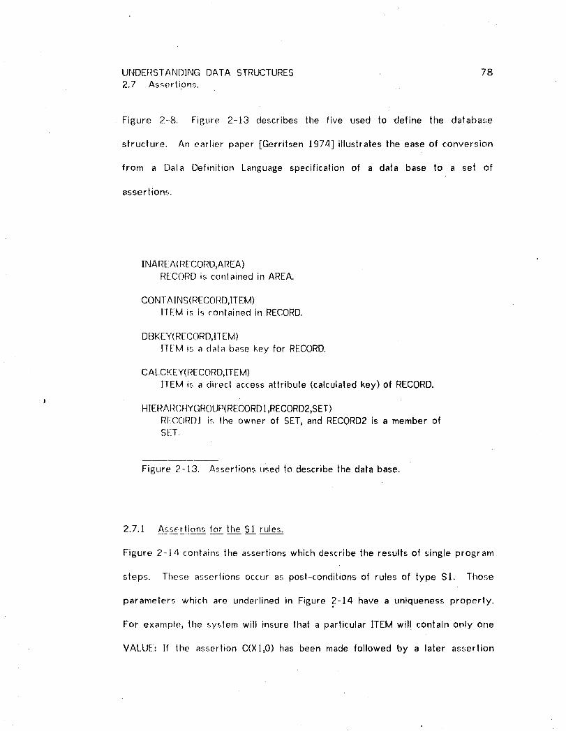
UNDERSTAND]NG DATA STRUCTURES 78
2.7 Assertipns.
Figure 2-8. Figure 2-13 describes the five used to define the database
structure. An earlier paper [Gerritsen 1974] illustrates the ease of conversion
from a Data Definition Language specification of a data base to a set of
asser|ions.
]NAREA(RECORD,AREA)RECORD is conlained in AREA.
CONTAINS(RECORD,ITEM)ITEM is is __ontained in RECORD.
DBKEY(RizCC)RD,II EM)ITEM is a data base key for RECORD.
CALCKEY(RECORD,ITEM)
ITEM is a direct access attribule (calculated key) of RECORD.
HIERA RC'HYGROUP(RECORD1,RECORD2,SET)RECORDI is the owner of SET, and RECORD2 is a member ofSEII[.
Figure 2-13. Assertions used to describe the data base.
2.7.1 Assertions for the S:I rules.
Figure 2-14 contains the assertions which describe the results of single program
sleps. These assertions occur as post-conditions of rules of type SI. Those
parameters which are underlined in Figure 2-14 have a uniqueness properly.
For example, the system will insure thai a particular ITEM will contain only one
VALUE: If the assertion C(X],0) has been made followed by a later assertion
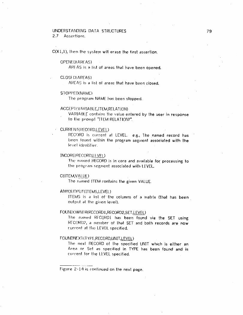
UNDERSTANDING DATA STRUCTURES 792.7 Assertions.
C(Xl,1), then the system will erase tile first assertion.
OPENED(AREAS)AREAS is a list of areas that have been opened.
CLOSED(AREAS)AREAS is a list of areas that have been closed.
STOPPED(NAME)
]he program NAME has been stopped.
ACCEP] (VARtABLE,1TEM,RELATION)
VARIABI_Econtains the value entered by the user in responseto the prompt "ITEM RELATION?".
CURRENI(RECORD,LEVEL)
RECORD is current at LEVEL. e.g., The named record hasbeen found wilhin the program segment associated wilh thelevel identifier.
INCORE(RECORD,LE-YEL)The narned RECORDis in core and available for processing tothe program segment associated with LEVEL.
C(ITEM,YA_LME)The named ITEM conlains the given VALUE.
ANYOUTPI.JT(t[EMS,LEVEL)ll-EMS is a list of the columns of a matrix (that has beenoutput at lhe given level).
FOUNDOWNER(RECC)RDl ,RECORD2,SET,L_EVEL)]he named RECORDI has been found via the SET usingR[CORD2, a member of that SET and both records are nowcurrent at the LEVEL specified.
FOUNDNEX](7YPE,RECORD,UNIT,LEVEL)The next RECORDof the specified UN]T which is either anArea or Set as specified in TYPE has been found and iscurrent for the LEVELspecified.
Figure 2-14 is continued on the next page.

UNDERSTANDING DATA STRUCTURES 802.7 Assertions.
FOUND( RECORD,ITE M,VAL__UELEVEL)The named RECORD has been found using ITEM as acalculated key with the given VALUE such that RECORD iscurrent for lhe specified LEVEL.
FOUNDUS [NG(RECORD,KEY,LEVEL)1-he named RECORD has been found using the data base KEY
and is current for the specified LEVEL.
FOUNDF IRST(TYPE,RECORD,UNIT,LEVEL)1-he named RECORD has been found as the first record of the
specified UNIT which is either a Set or Area as specified bythe value of TYPE. The record is current for th.e specifiedLEVEl..
Figure 2-14. Assertions which indicate the results of singleprogram statements.
There is a seman|ic redundancy in each of the FOUND... assertions and the
CURRENf assertion since a found record must be current, it would be possible
to eliminate this redundancy with a rewriting of the rules, and such a rewrile
would lead to a more concise system. On the other hand_ the redundancy
serves to guard against improper program, generation if (for example) a
particular rule has an incomplete pre-condition.
The assertions in Figure 2-14 appear to desc.ribe the status of an executing
program. The descriptions are more properly interpreted for program
generation if each is read as if preceded with the phrase "Code has been
generated such that...".

UNDERSTANDING DATA STRUCTURES 812.7 Assertions.
ISITEM(ITEM)
HEM is contained within some record as an attribute or database key.
BCAtt(COMMAND)COMMAND has the value "COUNT.... or "AVE".
BTMMA_t(CC)MMAND)
COMMAND has the value "TOT", "MIN", "MAX" or "AVE".
=(A,B)
A is eqtlal Io B.
EQ#(A,B)
A is equal to B. This assertion differs from the preceedingone in thai ils value can be uncertain ifl for example_ either Aor B are prograrn variables.
TEST(CONDITION,L EVEL)'
l he CONDIIlON is true for the program segment defined forLEVEL. CONDITION is a list consisting o.f a relation and twoarguments. When the arguments are program variable%TEST will have an uncertain value.
Figure 2-Jb. Other assertions.
2.7.2 Miscellaneous assertions_.=.
Figure 2-J5 contains a set of assertions which are difficult to classify. The first
is directly derivable from the assertions describing the data base structure.
The next Ihree are used to test the values of their arguments, and the last two
are used to tesl values or insert code to test values.
2.7.3 Assertions for the S3 rules.
Figure 2-16 contains the remaining assertions. These can best be classified as
UNDERSTANDING DATA STRUCTURES 822.7 Asserlions.
describing tile general status of the program or of particular program blocks as
tl-_ey are constructed. This is different than the assertions in Figure 2-14 which
describe the result of single program statements. All of the assertions of
Figure 2-].6 are post--conditions of type $3 rules. $3 rules serve to insure the
proper composition of individual operators or other program blocks into larger
program blocks.
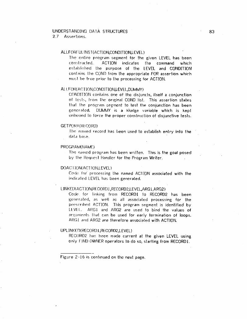
UNDERSTANDING DATA STRUCTURES 832.7 Assertions.
ALL FOR[ULINST(ACTION,CONDITION,LEVEL)The entire program segment for the given LEVEL has beenconstructed. ACTION indicates the command which
established the purpose of the LEVEL and CONDITIONcontains the COND from the appropriate FOR assertion whichrollS1 be true prior to the processing for ACTION.
ALLFOR(ACTION,CONDITION,LEVEL,DUMMY)
('()IXJD][]ON contains one of the disjuncts, itself a conjunctionof testr,, from the original COND list. This assertion stalesthat lhe program segment to test the conjunction has beengeneraled. DUMMY is a kludge variable which is keptunbound to force the proper construction of disjunctive tests.
GETPORT(RECORD)
lhe nmnecJ record has been used to establish entry into thedala ba_,e.
PROGRAM(NAME)
The named program has been written. This is the goal posedby the Request Handler for the Program Writer.
DOACI ]C)N(ACf ION,LEVEL)Code for' processing the named ACTION associated with theindkaled [.EVEL has been generated.
LINKED(ACI ION,RECORD],RECORD2,LEVEL,ARG t,ARG2 )Code for linking from RECORD] to RECORD2 has beengenerated, as welt as all associated processing for thepres(ribed ACT]ON. This program segment is identified byLEVEl[_. ARGI and ARG2 are used to bind the values of
ar_uments that can be used for early termination of loops.ARG] and ARG2 are therefore associated with ACTION.
UPLINKED(RECORD/,RECORD2,LEVEL)
RECORD2 has been made current at the given LEVEL usingonly FIND OWNER operators to do so, starting from RECORDI.
Figure 2-]6 is continued on the next page.
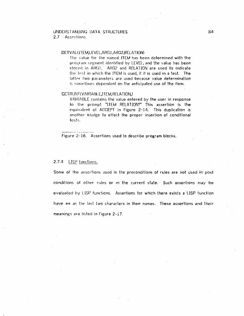
UNDERSTANDING DATA STRUCTURES 842.7 Assertions.
DETVAL(I 1 EM,LEVEL,ARG t ,ARG2,RELATION)The value for the named ITEM has been determined with the
pro._ram se.£;,ment identified by LEVEL, and the value has beenstored in ARG]. ARG2 and RELATION are used to indicate
the tf.._,t in which tile ITEM is used, if it is used in a test. Thelatter two parameters are used because value determinationis somelime_._ dependent on the anticipated use of the item.
GETRUNT(VARIABLE,ITEM,RELATION,)VAI_]ABLE contains the value entered by the user in responseto the prompt "ITEM RELAT[ON?" This assertion is theequivalent of ACCEPT in Figure 2-14. This duplication isanother kludge to effect the proper insertion of conditionaltest._,.
Fis;ure 2-16. Assertions usedto describe program blocks.
2.7.4 LiSP functions.
Some of the assertions used in the preconditions of rules are not used in post
conditions of other rules or in the current state. Such assertions may be
evaluated by t lSP functions. Assertions for which there exists a LISP function
have ## as the last two characters in their names. These assertions and their
meanin6s are listed in Fisure 2-17.
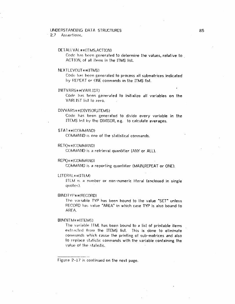
UNDERSTANDING DATA STRUCTURES 852.7 Assertions.
DETALI.VAL _ _(ITMS,ACTION)
Code has been generated to determine the values, relative toACTION, of all iterns in the ITMS list.
NEXTLEVOUT,_(ITMS)
Code has been generated to process all submatrices indicatedby I_EZPEATor ONE commands in the IIMS list.
INITVAR S, _(VARL IST)
Code has been generated to initialize all variables on theVARI.IST listIo zero.
DIVVARS_t _(DIVISOR,ITEMS)
Code has been generated to divideevery variable in the
ITEMS listby the DIVISOR,e.g. to calculateaverages.
STAf __,(COMMAND)
COMMAND is one of the statistical commands.
RETQ_,_(COMMAND)
COMMAND is a retrieval quantifier (ANY or ALL).
REPQ,.(COMMAND)
COMMAND is a reporting quantifier (MAIN,REPEAT or ONE).
LITERAL..(ITEM)
llEM is a number or non-numeric literal (enclosed in singlequotes).
BIND1 YP_ #(RECORD)The variable TYP has been bound to the value "SET" unlessRECORD has value "AREA" in which case TYP is also bound toAREA,
BINDITM..(ITEMS)
lhe variable ITML has been bound to a list of printable itemse×tr_tcted from the ITEMS list. This is done to eliminate
comlnands which cause the printing of sub-matrices and alsoto replace statistic commands with the variable containing thevalue of the statistic.
Figure 2-17 is continued on the next page.

UNDERSTANDING DATA STRUCTURES 86
2.7 Assertions.
BINDVAI #,(LIS],ITEM)
]he variable VAL is bound to the second argument of anequality test contained in the LIST which has ITEM as its first
arsument; e.5. (ITEM EO VAL).
READL_4(]I M REL)
This a':_,_:erlion returns the value "ITM REL?", which is used inthe 8eneraled program Io prompt the user.
CONT EST__(ACT ]ON,A RGI ,ARG2)This assertion returns a test which will be used for
terminating a loop. Appropriate tests for early terminationof lhe loop depending on the ACTION of the loop are alsoF.,enerated. An early termination test will involve ARGI andARC;2.
UNCERTEIRRSTAT_#()
This assertiol_ always evaluates to true. However it alsoinsures that all knowledge about the value of ERRORSTATUSbecomes uncertain. This is used to indicate that the value of
ERROI_STAfUS becomes unknown following a data baseaCCeSS.
Figure 2-17. Assertions evaluated by LISP.
Of the assertions in Figure 2-17, the first four are most-important as their
evaluation will spawn other goals and will eventually result in additional code
generation. The second four assertions (STAT## through LITERAL##) are very
simple and return true or false depending on the value of their single
parameter. The ne×t three assertions (all have BIND as the first four
characters) are Lised to bind variables to values extracted from lists. These
assertions are necessary because of the list structures contained in the
assertions generated by the Request Handler.

UNDERSTANDING DATA STRUCTURES 872.7 Assertion.,,.
The last three assertions are unusual in that they are not evaluated for truth or
failure. ]nsteact, they return a value or change the state as is explained in
Figure 2-17.
Occasionally the pre-condition of a rule will include standard LISP or
Micro-Planner predicates (see [McCarthy et al 1972] and [Sussman and
Winograd ]972]). These predicates are illustrated in Figure 2-]8.
Finally, Figure 2-]9 gives an alphabetical index of the assertions and predicates
in Figures 2-8 and 2-13 thru 2-18.
THSETQ(A,B)Sets Micro-Planner variable A to the value of B.
THASVAI.(A)True if variable A is bound to a value
NULL(A)A is null.
CAR(A)Returns the first element of the list A.
CDR(A)
Returns a list equivalent to A with its firsl element removed.
.iI Figure 2-J8. Standard LISP and Micro-Planner predicates used,, in the rules.

UNDERSTANDING DATA STRUCTURES 882.7 Assertions.
ASSERTION F__IG__=. ASSERTION FIG.___=.ACCEPI 2-14 GETRUNT 2-16ALLFOR 2-16 HIERARCHYGROUP 2-13ALI_FORFULINST 2-16 INITVARS## 2-17ANYOUTPUT 2-14 LITRAL## 2-17BCA_ 2-15 ]NAREA 2-13BINDIrML._ _ 2-17 INCORE 2- ] 4BIN[)I YP_ 2-17 ISITEM 2- l 5BINI)VAI__. 2-17 ISPORT 2-8
1SVAR 2-8BI MMA# 2-15 LINKED 2-16C 2-14 LINKS 2-8CAI.CKEY 2-13 NEXTLEVOUT## 2-17CAR 2-18CDR 2-18CI_(.)oED 2-14 NULL 2-18CON] AINS 2- / 3 OPENED 2-14CC)N] EST__ 2-17 PROGRAM 2-16CURRENT 2-14 READL## 2-17DBKEY 2-13 REPQ## 2-1 7DLIALLVAL## 2-17 RETQ## " 2-17DETVAL 2-16 STAT## 2-17D]VVARS#. 2-17 STOPPED 2-14DOCATION 2-16 TEST 2-15EQ. 2-15 THASVAL 2-18FOR 2-8 THSETQ 2-18FOUND 2-14 TOBEOPND 2-8FOUNDFIRST 2-14 TOBEUSED 2-8FOUNDNEXT 2-14 UNCERTERRSAT## 2-17FOIJNI)OWNER 2-14 UPLINKED 2-16FOUNDiJSING 2-14 = 2- | 5GKrPORT 2-16
Figure 2-19. Index to Figures 2-8 and 2-131hrough 2-18.

UNDERSTANDING DATA STRUCTURES 89
2.8 A Frame for the Semantics of Data Structures.
2.8.] Rules of l__y_p_e_.Sl.
Now that all of the assertions and predicates have been described, it is possible
to discuss the Frame that (in the logic of programs) forms an axiomatic
representalion of lhe semantics of data structures and DML procedure. The
rules of lhe Frame which describe simple operators (type SJ.) will be discussed
first. Each of these rules is of the form P{A}R where A is a single program
operation or command. The post-condition R will be one or more of the
assertions of Figure 2-14.
Each rule in Figure 2-20 is described with A, the operation, followed in order by
P, the pre-condilion, and R, the post-condition. The post-condition is further
identified by the preceeding _. Variables in each rule are underscored.
Operator rules are actually fairly simple, and only two will be discussed in detail.
The next to last rule of Figure 2-20, GET RE__Cis extremely simple and an English
interpretation i_._:
if REC is CURRENT in a particular program segment identifiedby !__EVSL__-then executing GET RE___CCwill insure that RE.__Cis]NCORE and available for processing by the particularprogram segmenl.
FIND REC RECORD is somewhat more complicated and the following interpretation
will ignore some of the assertions. In English:
If _REC_:- is a port and ]T___M_Mis a calculated key and is required tobe equal to VAL then either determine VAL interactively, or ifVAI is not equal to RUNT]ME simply move VAL to ITM.
UNDERSTANDING DATA STRUCTURES 902.8 A Frame for tile Semantics of Data Structures
Following the FIND, assert the record has been FOUND and isCURRENT but not INCORE. Also indicate that the value ofERRORSTA]US is ur)cerla n.
Note the equivalence between this rule and the <FIND> production earlier
discussed.

UNDERSTANDING DATA STRUCTURES 912.8 A Frame for the Semantics of Data Structures
MOVE VAL 10 []EST.ISVAR(DEST)vlSITEM(DEST)
C<p__E__S__,TVA_.__LL)
ACCEPT VAR.[lSll EM(VAR)vISVAR(VAR)]AANYOI.JTPUT((EV(READL##ITM REL)),VA._R)
-, ACCEPT(VA_.A_RIT__M,MRE.__LL)AC(VA__A__RRUNTIME)
DISPLAY ITML.
,-NULI.(ITM____L)
-_ ANYOUTPUT(ITM_.._L,LEVEL)
OPEN A_RREA.S.[OBEOPND(AREA__S)
-, OPENED(AREA._._S)
CLOSE AREAS.TOBEOPND(AREAS)
CLOSED(AR_._EA__SS)
FIND REC RECORD.
1SPORT(R_E__C)ACALCKEY(RE__QC,IT.__MM)^FOR(FORLl ST,LEVE_____E)A[THASVAL(VAL)vBINDVAL_,((EV(CAR FORLIST.)),IT__.MM)]A[_=(VAILRUNTIME)vACCEPT(IT__M_,MITM,EQ)]^C(ITM,VA L)
-, FOUND(RE_C_C,IT_T.__MVA___LLEVE.____L)ACURRENT(REC,LEVEL)A-,INCORE(R_.E_LEVE____L)^UNCERTERRSTAT# #()
FIND REC USING DBK.
DBKEY(RE__C,DB__.K.K)
-* FOUNDUSlNG(RE__CDB__B.._KLEVE____L_)ACURRENT(RE.E_CLEVEL)A_INCORE(RE___CLEVE______L)^UNCERTERRSTAT##()
Figure 2-20 is continued on the next page.

UNDERSTANDING DA]A SI'RUC_URES 922.8 A Frame for the Semantics of Data Structures
FIND FIRST REC RECORDOF UNIT 1-YP.
[=(_TY_P,SET)AHIERARCHYGROUP(OWN,REC,UNI__!)A[ =(O_W_.,NSYSTEM)vCURRENT(OWN,LEVEL____X)]]v
[=(TYP__,AREA)AINAREA(RE_.E_C_,CUNIT)]
' -_ FOUNDFIRST(TY___PRE_EC_,CUN._ITLEVE__L)ACURRENT(REC,LEVE_LL)A-,INCORE(_LEVE___LL)AUNCERTERRSTAT##()
FIND NEXT REC RECORDOF UNII TYP.
[=(T__YYP_P,AREA)AINAREA(RE_Q__CUNII)]v[=(TYP,SET)AHIERARCHYGROUP(OWN,REC,UNIT)A
[=(.OWjNSYSTEM)vCURRENT(OW_._NLEVELX)]] .
--_ FOUNDNEXT(TYP,REC,UN__ITLEVE___L)ACURRENT(REC,LEVE_L)A-INCORE(REE__CLEVE_____L)AUNCERTERRSTAT# #()
FIND OWNER RECORDOF S_T.TSET.H]ERARCHYGROUP(OWN,ME__MS_!)A-,=(OW._NSYSTEM)ACURRENT(_ME___M_LE__VEL_X)
-, FOUNDOWNER(O__W__NME._MSL LEVE_____L)ACURRENT(OWQ_W_NLEVE_._._LL)A-4NCORE(OWN,LEVE___L)AUNCERTERRSTAT##()
GET REC.
CURRENT(RF__E__CLEVEL)
-_ INCORE(.R_EC_,LEVE__LL)
STOP,-,STOPPED(NAM)
-_ STOPPED(NAM)
Figu.re 2-20. Operator (type SI) rules.
2.8.2 ]te_ra_!i__nr_t!e_: ly_peS__2.
Figure 2-2! contains the single iterative rule used by the DMLP. The code
generated by this rule matches that produced by <LOOPCONTROL>and <LOOP

UNDERSTANDING DATA STRUCTURES 932.8 A Frame for the Semantics of Data Structures
BODY>. The rule is described with' a pre-condition, loop invariant, iteration
step, iteration test and a post-condition. The pre-condition and iteration test
correspond to <LOOP CONTROL>. The loop invariant and iteration step is
.captured in the <LOOP BODY>. The variable Y1 as used in the example of
Figure 2-12 is specifically introduced by the system to insure the loop invariant.
The only post-condition of the Iteration Rule is a LINKED assertion. This means
that a loop is constructed for the purpose of accessing the GREC record, e.g.,
The goal which invokes the iteration is to find an access path from PREC to
GREC and then perform the ACTION. Since a single loop traverses a single
hierarchy it will establish a path from PRECto REC.
If REC is equal to GREC, the access path has been completed. If not, the rule=
can be recursively entered to complete the path from REC to GREC. Such
recursive entry of the rule will result in nested loops. The STAYUP rule
(described below) insures an end to the recursion by checking if PRECand GREC
are the same, in which case the access path has been completed.
(CURSTAT,A,I_,._.)is a function which is expanded to "CURRENCYSTATUS FORA
B".

UNDERSTANDING DATA STRUCTURES 942.8 A Frame for the Semantics of Data Structures
PRE-(;()Ni]IIIQN:
BINDTYP#_.(_PREC)A[[ [:_([_R!;_C,AREA)vHIERARCHYGRO[IP(PR__EC_UNIT)]A
THSETQ(REC,GREC)]vHIERARCHYGROUP(_RE__CUN|T)]^FOUN[]F]RST(TYP,RE_CLIN_.I.I.I.I.I.I.I_ITLEVEL)ADBKEY(RE__CDBK)AC([)BK,(CURSTAT,_T Y_y_P0))
INVARIANT:
C(I]BK.,CURRV)
ITERATION STEP:
LlNKED(ACTLO_.,NRF_E_CGR____ECLEVEL_,AR_IA R2)AC(!__E,(CURSTAT,_TY_y_DPCURRV))AFOUNDUS ING(R__EC,D_B_,KLEVEL)AFOUNDNEXT(TYP,REC,UNIT,LEVEL)
LOOP TERMINATOR:
CONTEST__((EV(CARACTION.)),AR}__,AR2)
POSf-CONDITION:t.INKED(_ACT;ON_P_RRE__Q.,C__ AR_A_R_I,IAR2)
Figure 2-21. The iteration rule.

UNDERSTANDING DATA STRUCTURES 952.8 A Frame for the Semantics of Data Structures
TOPPROG
LINKS(ACTION__,PORT,GREC,L_.EVEL)AOPENED(AREAS)AGETPORT(PREC)ALINKED(ACTLION__,P_R_RE__C_,CGR_.R_EC,ECLEVEbNIL,NIL)ACLOSED(AREAS)ASTOPPED(NAM)
-* PROGRAM(NAM)
PDR'_DEF
[ISPORT(R_E__C_C)AFOUND(RE__EC_CIT__M_MVAALjL×)]v[-,iSPORT(DREC)ALINKS(_DU_[,IPORT,_X)A
THSETQ(_REC_,$YSTEM)AUPLINK(GR_RE_E_C_,CCECREC)AIV[-,lSPORT(DR_EC)ATHSETQ(RE_CAREA)]
-, GEl PORT(REC)
STAYUP
[[ =(_R_EC.,GREC)^CURRENf(REC_LEVEL)]v[-,---(R_EQ_SYSTEM)A-,=(RE___CAREA)m
UPLINKED(REC:,GREC,LEVE_)]]A[-=((EV(CAR ACTION)),ALL)vC((EV(CADRACTION.)),!)]A[[._FOR(E()P,L[S,LEVEL)ADOACTION(ACT_CTi_CTi__ONONiONLEVEL)Iv
' [FOR(FO_R_[:.LSj.LEVEL)A. ALLFORFULINST(ACTIO__NF_ORLIS,LEVEL)]]
--_ L]NKED(ACT]ON,REECjCGREC,LEVE...VE._ELAR_E[,1AR2)
UPN]ERARCHY
FOUNDOWNER(GR_._ECMEM,S_._TLEVEL)v[FOUNDOWNER(OW_N,ME___MS_.__TLEVEL)AUPLINKED(OWN,GREC,LEVEL)]
UPLINKED(MEME_MjMGRE__CLEVEL)
ALLFORFULINSTDEFA[.LFOR(ACTION,(EV(CARFORLIS)),LEVEL,DUMMY)AALLFORFULINST(_(EV(CDR FORLIS)),LEVEL)
-* ALLFORFULINST(__LEVEL)
Figure 2-22 is continued on the next page.
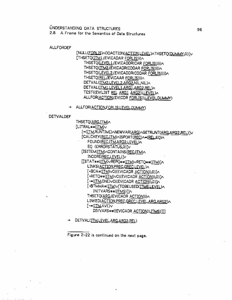
UNDERSTANDING DATA STRUCTURES 962.8 A Frame for the Semantics of Data Structures
ALLFORDEF[NULL(,ED.EI.,_)ADOACTION(ACTION,_)ATHSETQ(P__,0 )Iv[THSETQ(ITM1,(EV(CADARFORLIS)))A
THSETQ(LEVEL1,(EV(CADDR(CAR_)))^THSETQ(ITM2,(EV(CADR(CDDARFORLIS))))^TFISETQ(LEVEL2,(EV(CADDR(CDDARFORLIS))))^THSETQ(,_,(EV(CAAR FORLIS)))ADETVAL(]_TM2,LEVEL2,ARG2,NIL,NIL)ADETVAL(ITM1 ,],.EY_[,_AR_ ,ARG2,REL)^TEST((EV(LIST _ _AR.._ARG2)),.LEVEL)AALLFOR(ACTION.,(EV(CDRFORLIS)),LEVEL_DUMMY)
--) ALLFOR(ACTION,FORLIS,LEVEL,DUMMY)
DETVALDEFTHSETQ(ARG,ITM_A[LITRAL##(_v
[-(!T__MRUNTIME)ANEWVAR(ARG)AGETRUNT(AR_._GARG2,REL)]v[CALCKEY(RE__jC_A]SPORT(REC)A-(_,EQ)A
FOUND(REC,IT___M_LEVEL)AEQ (ERRORSTATUS,0)]v
[[SITEM(ITM)ACONTAINS(REC,ITM)AINCORE(REC,LEVEL)]v
[[STAT##(ITM)vREPQ##_vRETQ##(IT_]ALINKS(ACTION,PRE.C,RCagZ._LEVEL)A
[_BCA_(ITM)vC((EV(CADR ACTION_)),0)]A[_RETQ_#(IT_)vC((EV(CADR ACTIO..N.)),O)]A[_=(ITM,ONE)vC((EV(CADRACTION_),0)]A[_BTMMA#(!.T..M)v[TOBEUSED(1TMS,LEVEL)A
INITVARS##(ITMS)]]A. THSETQ(_(EV(CADR ACTION)))A
LINKED(ACTION,PREC,G_LEVEL,ARG,ARG2)A[_=CIT_AVE)v
DIVVARS##((EV(CADRACT_ )),IT._T..._.._SJ]]]
..,DETVAL(ITM,LEVEL,AR_.R.G_,GARG2,REL)
Figure 2-22 is continued on the next page.
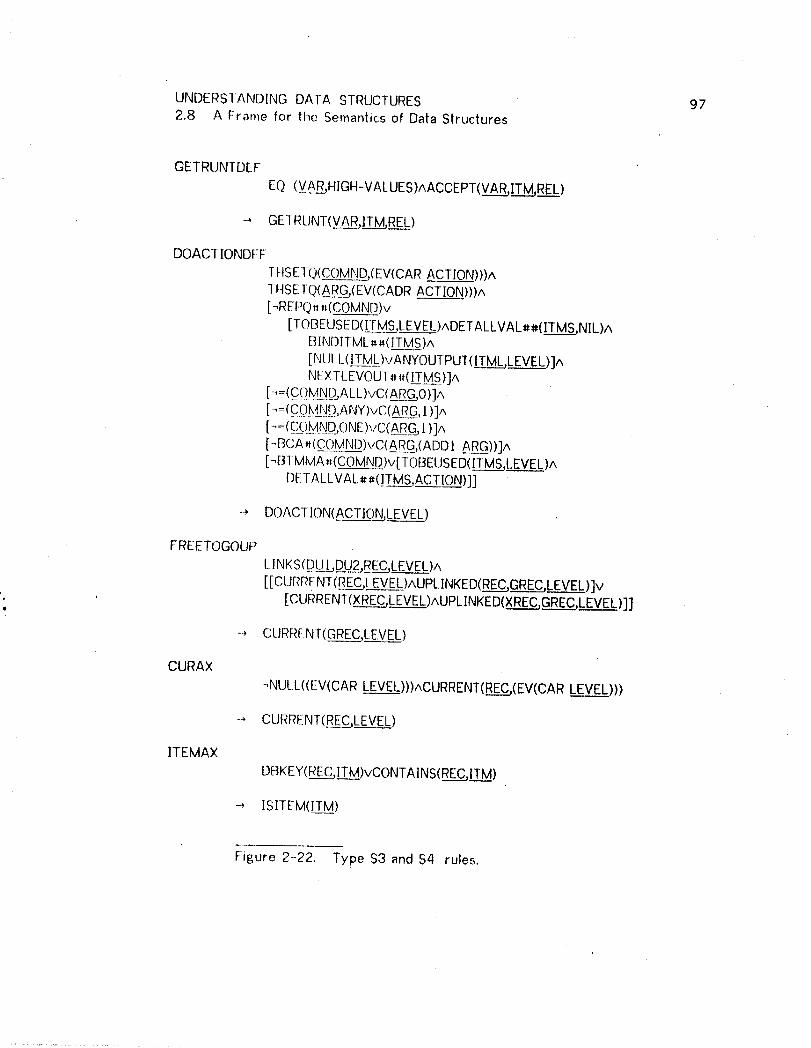
UNDERSIANDING DATA STRUCTURES 972.8 A Frame for the Semantics of Data Structures
GETRIJNTDEF
EQ (VAR,HIGH-VALUES)AACCEPT(VAR,_REL)
-_ GETRLJNT(VA.R_,IT.._MREL)
DOACIIONDEF
I HSETQ(C_OM__ND(EV(CAR ACTION)))A1 HSETQ(AR_G(EV(CADRACTION)))A[_REPQ,_(COMND)v
[TOBEUSED(ITMS,LEVEI_)ADETALLVAL##(_NIL)ABINDITM[.##(]TMS)A[NULL(ITML)vANYOUfPUT(1T___MLLEVEL)]ANEXTLEVOUT._(I._TMS)]A
[_ =(C(]M_N[)jALL)vC(AR_GjO)]A[-,=(C.0k4_J[)_,ANY)vC(ARG,] )]A[- =(.C_QNN_D_ONE)vC(A[_G_, t )]A
[-BCA,(COMND)vC(ARG,(ADD1 ARG))]A[-BTMMA_(COMND)v[TOBEUSED(ITMS,LEVEL)A
DETALLVAL_*(1TMS,ACTION)]]
-, DOACTION(_A_CTIOjNLEVEL)
FREETOGOUPLINKS(DLIbD_U2,_REC_,CLEVEL)A[[CURREN1(REC,LEVEL)AUPLINKED(RE__EC.,CGREC,LEVEL)]v
. [CURRENT(XREC,LEVEL)AUPLINKED(XREC,GREC,LEVEL)]]
-_ CURRENT(GREC,!_EVEL)
CURAX
_NULL((EV(CARLEVEL)))ACURRENT(REC,(EV(CARLEVEL)))
-., CURRENT(RE_CLEVEL)
ITEMAX
DBKEY(REC,ITM)vCONTAINS(REC,ITM)
-* ISITEM(ITM)
Figure 2-22. Type $3 and $4 rules.

UNDERSIANDING DATA STRUCTURES 982.8 A Frame for the Semantics of Data Structures
2.8.3 Typ_e $3 and S,1 rules.
In Figure 2--22 each rule is labeled, the pre-condition is described and then the
post-condition is given preceeded by a '%". Four of these rules_ ALLFORDEF,
ALLFORFUL|NSTDEF, UPHIERARCHY, and CURAX are recursive.
2.8.3.1 [he STAYI.IP rule.
The SfAYUP rule checks for completion of an access path. The first disjunction
in the pre-condition of STAYUP, consisting of the first four assertions, insures
thai either _..E_Cand GREC are the same and current or code has been generated
linking R__ECto GREC with FIND OWNER operations only.
The next disjunction of two assertions forces the quantification flag for ALL
(only if such quantification has been specified as the ACTION) to be temporarily
false, if the condition test succeeds then the flag will be reset to true. At the
end of the iteration, the flag will have its proper value.
The next disjunction of STAYUP (four assertions) specifies immediate
construction of the code for the specified ACTION if the activity is not
conditional. If the activity is conditional then ALLFORFULINST will insure
generation of the code for conditional testing as well as actually performing the
action. STAYUP is equivalent to the <ACTION> production.
Rather than describing all of the remainin 8 rules in detail, Figure 2-23 gives

UNDERSTANDING DATA STRUCTURES 992.8 A Frame for the Semantics of Data Structures
correspondences between the productions of Figure 2-11 and the rules.
However, informal descriptions of several of the rules follow.
RUI.E PRODUCTIONTOPPROG <MAIN PARAGRAPH>PORI DEF <PORT>STAYIJP <ACTION>
UPHIIIRARCHY ':F]NDOWNER SEQUENCE> in <ACTION>ALLFORFULINSTDEFA[_LFORDEF <CONDITION TEST>
DETVALDEF <VALUE DETERMINATION>,<CONDITION VALUE>GEl RUNIDEF <RUNTIME>
DOACflONDEF <DISPLAY SEQUENCE>,<STATISTIC SEQUENCE>FREEIOGOUP <FINDOWNER SEQUENCE> in <VALUE DETERMINATION>
Figure 2-23. Rule and production correspondences.
2.8.3.2 -[Ij_ DOACfIONDEF rule.
DAOCTIONDEF contains many disjunctions of the form -,AvBwhich of course has
the same effect as A_B.
ACTION is a list consisting of a command and a variable which is available for use
in satisfying the command. The first assertion extracts the command from
ACTION and stores it in COMND. The second assertion extracts the variable and
stores it in VAR.
The first disjunction (incorloorating the next seven assertions) specifies that if
UNDERSTAN[_]ING DATA STRUCTURES 1002.8 A Frame for the Semantics of Data Structures
the COMND is a report quantifier, then generate the followin8_ in order:
(a) Code to determine the values for all [TMS to be used in
this program segment (DETALLVAL#_).
(b) Code to display tile matrix (ANYOUTPUT).
(c) Code to handle all sub-levels within thecontext of theoutrent level (NEXTLEVOUT##).
The next three disjunctions (six assertions) cause code to be generated to set
ARG to zero or one if theCOMNDis aquantifier. The next to the last disjunction
(three assertions) causes ARG to be incremented by one if the COMND is a COUNT
or AVE.
The last disjunction in DOACTIONDEF causes code generation for processing the
[TMS matrix according to the statistical command given in COMND. This code will
either total all of the columns of the matrix or find the minimun or maximum
entry in each column.
2.8.3.3 The ALLFOf,_DEF rule.
ALLFORDEF is another important rule. This is a recursive rule' which conlrols
code generation for a conjunctive list of tests (contained in FORLIS). Each
iteration of the rule will result in code generation for one such test. The first
three assertions of ALLFORDEF will (a), terminate the recursion when all tests in
FORLIS have been taken care of (FORLIS is empty) and (b)p cause code
generation for the conditional ACTION associated with FORLIS.

UNDERSTANDING DATA STRUCTURES 1012.8 A Frame for the Semantics of Data Structures
]f FORLIS is nol empty then the next five predicates, all THSETQ, extract the five
parameters describ!n8 the first test in FORL]S. These fiye parameters were
described in section 2.5.2. The next two assertions in ALLFORDEF, both
DETVAL, insure code 6eneralion for the value determination of the two
arsuments which are to be compared in the test. The next assertion causes
insertion of a conditional statement if the truth value of the relation is not
known. The last assertion causes the recursion and insures the proper code
8eneration for the remaining tests in FORL|S.
Section 2.5.2 stated that a complete condition is actually a disjunctive list of lists
of test conjunctions, yet ALLFORDEF is apparently only processing a conjunctive.!
list of tests. That is why ALLFORFUL[NSTDEF, another recursive rule, is
included. ]his rule is entered once for each list of conjunctions, e.g. once for
each disjuncl in the complete condition. ]n other words, ALLFORFULiNSTDEF
passes the fir_,t list of tests (CAR FORLIS) to ALLFORDEF and then recursively
enters itself with the remainin8 lists, e.g. (CDR FORLIS).
2.8.3.,1 The CURAX axiom.
CURAX is a simple axiom. |t is interesting because it is recursive and uses time
Dewey-decimal structure of LEVEL. CURAX specifies that a record is CURRENT
at a particular level if this level is within the context of another level in which
the record is already CURRENT. ]n other words, to find out if a record is
current at X.2.1, CURAX will see if it is current at X.2. (CAR .LEVEL) returns the

UNDERS1ANDING DATA STRUCTURES 1022.8 A Frame for the Semantics of Data Struclures
value X.2 because X.2.1 is represented in a list structure as ((X.2).1).
2.8.3.5 The. P_)R_TD_E_F_rule.
It was brou[_ht out earlier that there are three methods of eniry to a DBTG data
base. An entry point is called a port. The physical beginning of an area is a
port, as is a record which can be directly accessed. Finally, DBTG lets the user
define sets which are owned by the SYSTEM.' What this really amounts to is
that the data management system stores the direct access key of tt_e first
record of such a set in an internal table. A SYSTEM owned set is therefore
directly accessible and can be used as a port.. Since a set or area can contain
more than one record, a program loop is required to access all of the records in
the set or area.
PORTDEF contains three disjunctions in its precondition, one disjunction for each
type of port. The type of port selected is preferred by PORTDEF in the
following order" direct access, SYSTEM owned set, or Area search. The first
two assertions will be true if a direct access is possible, and code has been
constructed for this purpose. The second disjunct is true only if the top level
record of the query (GREC) is directly or indirectly owned by the SYSTEM. If
neither of the two preferred ports can be used ttien an Area search is forced
by setting !_E(_.to the value AREA.
, PORTDEF only generates code if a loop is used as a port. The code generation

UNDERS'rANDING DA'fA STRUCTURES /032.8 A Frame for the Semaniics of Data Structures
for other ports occurs when the Prosram Writer attempts to sa|isfy the LINKED
8oal followin8 the GETPORT goat in TOPPROG. Satisfyin8 this 8oal will £_enerate
the code for the access path from PREC to GREC. Recall that GREC is the
top-level conte×t record and that PREC has been bound by GETPORT to one of
three values: the name of the direct access record, the keyword SYSTEM or the
keyword AREA. Note that even if a direct access port is used it need not be
the lop level record of the query,
UNDERSTANDING DATA STRUCTURES 104
2.9 Efficiency_ Considerations.
2.9.1 Code duplication.
The programs generated by the system are far from optimal. The generated
programs are frequently larger than necessary because of the repetition of
equivalenl program blocks. This occurs if a particular block is needed in more
than one location in lhe program.
2.9.2 Data characteristics.
Program conslruclion also occurs in the absence of any information about data
characteristics such as data volumes and distributions. As a result, arbitrary
choices are frequenlly made where alternative program constructions are
possible. One such arbitrary decision which can impact program efficiency
depending on unknown (to the system) characteristics is port selection.
The system prefers to use a SYSTEM owned set as a port rather than an area
search if a direct access port is not possible. Yet, if one of the target records
occurs relatively infrequently in a (physically) small area, then the area search
is preferred.
An area search rnay also be preferred if the alternative SYSTEM owned set
"meanders" lhrough the data base. Searching such a set can require more
:' physical accesses than searching the entire area containing that' set. This may
occur if the unit of physical acces% called a page, contains more than one

UNDERSIANDING DAIA STRUCTURES 105
2.9 •Efficiency Considerations.
record. 'In Figure 2-24 each large box is a page of an area, and each "X" is a
target record of the query. All of the target records are contained in a system
owned set as illustrated by the arrows. It would require a total of seven page
accesses to traverse the set, yet an area search would require only four
accesses.
iX x ! X _ X.. i
X x r X
, p
Figure 2-24. Area searchvs a SYSTEM owned set search.
2.9.3 Coniunction testin.&.
Although, the system ignores efficiency factors in most of its decisions, there
are some instances in which efficiency considerations are reflected in tile
programs constructed. One such instance is exhibited in the construction of
tests for conjunctions. Rather than testing the entire conjunction in a single IF
statement, each conjunct is tested separately. Although this may lead [o a
UNDERSIANDING DATA STRUCTURES 106
2.9 Efficiency Considerations.
somewhat lar6er program than necessary, the separation of conjuncts will lead
to a more efficient execution.
The increased efficiency results because separatin8 the tests minimizes the
number of test preparations that will be necessary to evaluate the complete
condition. Because all tests are part of a conjunction, the i-th test is only
necessary if fhe preceeding (i - 1) tests are all true. Since a test preparation
can involve many data base accesses (in the calculation of a statistic, for
example), minimizin 6 Such lest preparations can have a dramatic effect on
program execution time and accesses to secondary storage.
2.9.4 Orderin6of tests.
The system currently 6enerates test evaluations in the order they are
presented in the query. Re-ordering these tests accordin8 to cost of the
necessary prep_4ration (lowest first) and expected failure rate (highest first)
would further increase execution efficiency.
2.9.5 E_aL['/_termination of PERFORM.
Increased efficiency in prosram execution also results from the code generated
by the system as described by the <SYSTEM TEST> production. The inclusion
of a <SYSIEM 1ESf> in a <CONTROL TEST> is necessary only if the loop is
controlled by the ONE quantifier. The <SYSTEM TEST> will terminate execution
of the loop after one line of the matrix has been displayed. The use of

UNDERSTANDING DATA STRUCTURES t07
2.9 Efficiency Con._Jderalions.
<SYSTEM TEST> with the logical quantifiers is not necessary but s|rongly
suggested t,ince there is no reason to continue execution of the loop a6 soon as
existential (ANY) quantification has been proved or universal (ALL) quantification
has been disproved. An example of this use can be seen in Figure 2-/2.
A system te-_4 can also be used to terminate the execution of loops which
calculate a COUNT, a M|Nima or a MAXima, if lhe result of the calculation is to be
used in a lest. This is possible because the value of such a calculation will vary
monotonically during execution of a loop. The value of a COUNT or a MAX
always increases. The value of a M]N will only get smaller. An AVErage will
never behave monotonically unless values are first sorted, and a TOTal is
monotonic only if ils possible set of arguments contains numbers which are all of
the same sign.
Therefore, if the value which is being calculated in the loop is to be compared
with a known value, the loop can be terminated if the COUNT or MAX is greater
(or the MIN is less) than the known value. Note that the actual relation used in
the test is not used to determine the relation used in the system test. The
effect of the system test can be made stronger in certain cases depending on
the relation in which the statistic is to be tested. For example, if the test is
"COUNT LT ]0", then the system test can be the stronger "COUNT GE [0" rather
than the standard "COUNT GT 10".

UNDERSTAND|NG DA'fA STRUCTURES 108
2.9 Efficiency Considerations.
DMLP generates the "standard" system test. The simple extension to generate
stronger testr_ would definitely be warranted in a "production" implementation.
[n determining the values of "A" and "B" in (A REL B), the system first
determines the value of "B", then the value of "A". This permits early loop
termination in determining the value of "A" because the value of "B" is known.
I'mproving I)MLP so that it can choose which of "A" or "B" to evaluate first would
permit early loop termination when determining the value of "B" as well.
UNDERSTANDING DATA STRUCTURES 109
2.10 ALGOL TO COBOL Conversion.
Programs constructed by the APG system are written in an Algol-like language.
The DMLP (which uses the APG) must translate this to COBOL and DML
Algol [Naur el al I960], as its name suggests, is an algorithmic language. The
Algol-like language generated by the APG system uses labels very sparsely'.
program labels are only referenced at disjunctive branches in the program. At
such a point of disjunction, the APG system generates a conditional branch to a
subroutine which encompasses all alternatives but one. Then code generation
continues for tile excluded alternative. The current state and the goal for the
sub-routines are saved. After completely generating the main program, the
system recalls the goal and state, and commences program generation of the
subrouiines.
The conversion process from the Algol-like language transforms each such
subroutine to a sub-section of the COBOL program. The main routine becomes
the main section of the program. This explains the distinction in the BNF
description of section 2.6 between <MAIN SECTION> and <SUB SECTION>. The
conditional branch in tile COBOL program is effected with a PERFORM of the first
.paragr.aph in the sub-section. The first paragraph in the section is performed
{rather than the section itself) to insure thai program control will not flow
sequentially out of the first paragraph.
UNDERSIANDING DATA STRUCTURES II0
2.t0 Algol 1o COI30L Conversion.
The need for sub-sections only arises if the query contains a disjunctive
condilion. The sub--section is entered only if the first disjunct fails. The first
step in the sub-section tests the second disjunct. DMLP generates a branch to
a second sub-section if there is a thirddisjunct in the condition. If there are no
further disjuncts in the condition, then DMLP inserts the clause "NEXT
SENTENCE" in place of the conditional branch.
Labels are used in the Algol-like programs only to transfer program control to
sub-routines. All program control within a routine is accomplished via
appropriale nesting of program blocks. Although COBOL allows nesting of IF's,
the nested [F"s 6ire a program a messy appearance, much less clear, in fact,o
than the equivalent in Algol. Fur|hermore, COBOL does not allow the nesting of
blocks which may be repetitively executed. Each such block must be either a
named paragraph, a named section or a contiguous set of named paragraphs or
named sections. ]-hat is not 1o say that program control cannot be logically
nested; e.g., it is perfectly legal in COBOL to repetitively execute a block from a
block which is being repetitively executed..The point is that in COBOL the
nesting is not physical in the program text; instead, it is accomplished by
labeling the blocks and then using the labels as the object of a PERFORM.
Transformalion from Algol structure to COBOL structure requires changing a
nested block structure to a sequentially labeled block structure. The process of
this transformation is simple.

UNDERSTANDING DATA STRUCTURES t ]. t
2./0 Algol to COBOL Conversion.
The complete Algol-like program is stored in a LISP list structure in the obvious
way_ e.g., each nested segment forms a sub-list. Conversion proceeds as
follows; lranslate each lop level element of the list to the appropriate program
statement unless the element is itself a list, e.g., a nested program block. If
such a nested block is encountered then generate a new paragraph name and a
program slatement which performs the new name, extract the sub-list containing
the nested block from the main list and push the new paragraph name followed
by each element of the sub-list onto the end of the main list. Further levels of
nesting are lhen properly processed in due course because each such block
eventually becomes a top level element of the main list.
In addition to struclural differences between Algol and COBOL, there are also
syntactic difference.._. The syntactic conversion is accomplished by a simple
table look Lip process in a table of clause "masks". This process also cleans up
such things as double negatives in logical statements. For example,-_LE is
changed in two steps, first to GT and finally to "[S GREATER THAN".
Figure 2-25, gives the Algol-like program generated by the APG system for the
query of FiE.ure 2-6. Contrast this with Figure 2-26 which is the COBOL
equivaienl of Figure 2-25.
The generated COBOL would be completely consistent with the specification in
[CODASYL |970] if certain instances of the MOVE statement are replaced by a

UNDERSTANDING DATA STRUCTURES ! 122.tO Algol 1o COBOLConversion.
COMPU1E statement. The generated programs may also make use of a MiN or
MAX function which is not standard in COBOL.
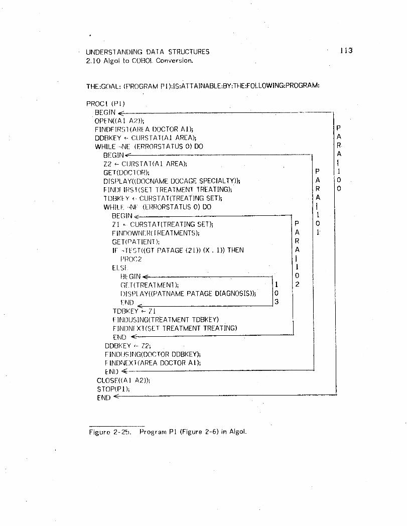
UNDERSTANDING DATA STRUCTURES !132.110Algol to COBOLConversion.
THE:GOAL: (PROGRAM PI):Is:ATTAINABLE:BY:THE:FOLLOWING:PROGRAM:
PROCI (PI)BEGIN <OPEN((A1 A2));FINI)FIRS1 (AREA DOCIOR A1);DDBKEY _- CLIRSTAT(AI AREA); AWHILE -,N_: (ERRORSTATUS0) DO R
BEGIN_ AZ2 _- CURSTAT(AI AREA); IGET(DOCIOR); P l[)ISPLAY((DOCNAME DOCAGESPECIALTY))_ A OF-INDf.IRSI(SE1 IREATMENT TREATING); R 0
TDBKI_!Y ,,--CURSTAI(TREATING SET); AWHILE _N[; (ERRORSTATUSO) DO /
BEGIN < 1Zt _-CURSTA1(TREATING SET); P 0FINDOWNER(TREATMENTS); A IGET(PATIENI ); RIF -qlJST((GT PATAGE (2t)) (X. I)) THEN A
PR(}C2 IELSE I
GEt(1 REA-iMENT); 1 2DISPLAY((PATNAME PATAGE DIAGNOSIS));
I:::ND<TDBKEY _ Z!FINDUSING(TREATMENTTDBKEY)FINDNEXT(SET TREATMENTTREATING)END <
DDBI<EY,-- Z2;F1ND[JSING(DOCTORDDBKEY);FINI)NEX1(AREA DOCTORAI);END <
CLOSE(CA] A2));STOP(P! );END <
Figure 2-25. Program PI (Figure 2-6)in Algol.

UNDERSTANDING DATA STRUCTURES t/42.10 Algol to COBOLConversion.
THE:GOAL: (PROGRAMPI ):IS:ATTAINABLE:BY:THE:FOLLOWING:PROGRAM:
PROCEDUREDIVISION.PROC1 SEC] ]ON.PARA- ! 00.
OPEN AREA At A2 .FIND FIRST DOCTORRECORDOF A1 AREA.MOVE CURRENCYSTATUS FORA1 AREA•TO DDBKEY.PERf:ORMPARA-IOI UNTIL ERRORSTATUSIS NOT EQUAL TO 0.C[OSI: AREA AI A2.STOP .
PARA- l 0 t.MOVE CURRENCYSTATUS FORA1 AREA TO Z2 .GET DOCTORRECORD.DISPLAY DOCNAMEDOCAGESPECIALTY.FIND FIRST TREATMENTRECORDOF TREATING SET.MOVE CURRENCYSTATUS FORTREATINGSET TO TDBKEY.PFRFORMPARA-102 UNTIL ERRORSTATUSIS NOT EQUALTO 0.MOVE Z2 10 DDBKEY.FIND DOCIOR USINGDDBKEY..FIND NEXT DOCTORRECORDOF A1 AREA.
PARA-102.
., MOVE CURRENCYSTATUS FORTREATINGSET TO ZI .FIND OWNERRECORDOF TREATMENTSSET .
• GET PATIENT RECORD.IF PAIAGE IS NOT GREATER THAN 21 NEXT SENTENCE
ELSE PERFORM PARA-I03.MOVE ZI IOTDBKEY.[IN[) ! REATMENTUSINGTDBKEY,FIND NEXT TREATMENTRECORDOF TREATING SET.
PARA- ] 03.GET TREATMENT RECORD.DISPLAY PATNAME PATAGE DIAGNOSIS.
Figure 2-26, Program PI in COBOL.
UNDERSTANDING DATA STRUCTURES I15
2.1 I Examples of Procedure Generation.P
This seclion concludes Chapter 2 with several examples of procedure
generation. For each example the query is given followed by the generated
COBOL program. -[he specific features demonstrated by each query are
classified and indexed in Figure 2-27. Program PI of the feature index is the
program of Figure 2-26.
' Two different data base structures were used for these examples. The first is
for a community medical data base. This data base contains information on all
hospitals, doctors and patients in a community. The structure for this data base
is illustrated in Figure 2-28. The data structure diagrams use the following
conventions: Record, set, and area names are in upper case, item names are in
lower case, and calculated keys are underlined. Area boundaries are indicated
with a dashed line. Other conventions of DS diagrams were discussed in
Chapter One.
Each record type also has a working storage register associated with it which
the DBTG calls a data base key. This data base key can be used to store the
data base address of a record occurence. The data base key for each record
has been indicated in parenthesis.

UNDERSTANDING DATA STRUCTURES " 162. I 1 Examples of Procedure Generation.
PROGRAM: P.J.IP_22 P3 P_44 P5 P6CONDITIONS:
COMPLEX X X XDISJUNCTION XCC)NJUNC[ ION X XQUANTIFICATION XUSE OF STA]ISTIC X X
DISPLAYNESTED MATRICES X X X X X!CONFLUENT t lIERARCHY X XDOWNWARDMIGRATION X X X!SIATIS I[(C XCONDIIIONAL X X!"ONE" COMMAND X
INTERACTION:CALCKEY VALUE X X XOTHER VALUE X X
PORT:CALCKEY X X XSYSIEM SET X XAREA S[ARCH X
DATA BASE'.MEDICAL X X XSALES X X X
Figure 2-27. Index to lheexamples.

UNDERSTANDING DATA STRUCTURES 1172.11 Examples of Procedure Generation.
At AREA HOSPSET A2 AREA
SEXHDR RACEHDR HOSPITAL DOCTOR(SDBKEY) (RDBKEY) (HDBKEY) (DDBKEY)
Sex Race _ Docno,AddressX Hspaddress Docname_Docage
X Hospname Specialty
,/\ /SEXSET _,4RAC_S ET L.?TSET_] _ORKSFOR WORKING
[PATIENT I I IwoR<REc*/
[ (PDBKEY) t i I(WDBKEY) II Palno,Patname I l I
BILLINGS _T:EArM_S j TR_EATING
/ ............_........../B1LI EN[RY i TREATMENT(BDBKEY) I {TDBKEY) ICode,Dale I Diagn°sis I
Amount 1 IORDERSET
J;ORDERS(ODBKEY).OrdnoPrescription
Figure 2-28. A community medical data base struclure.
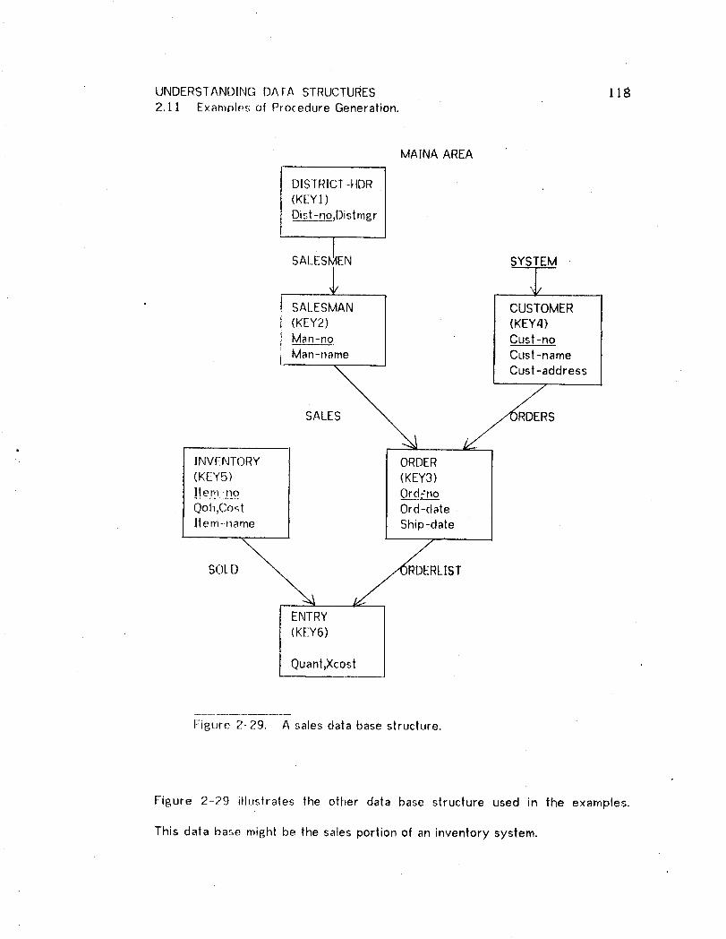
UNDERSTANDING DATA STRUCTURES !182.11 Examples of Procedure Generation.
MAINA AREA
DISTRICT-HDR(KEYI)_Djst--n£,Distmgr
SALESMEN SYSTEM
__4_SALESMAN CUSTOMER(KEY2) (KEY4)Man-no Cust -noMan-name Cust-name
Cust-addressSALE _RDERS
.INV[-NTORY ORDER(K[-Y5) (KEY3)
!t e.n!;:.to O_r(!iTn_£oQoh,Cost Oral-dateItem-name Ship-date
ENTRY
(KEY6)
Quant,Xcosl
Figure 2-29. A sales data base structure.
Figure 2-29 illustrates lhe other data base structure used in the examples.
This data base might be the sales portion of an inventory system.
_ UNDERSIANDING DATA STRUCTURES ! 19, : 2.J. ]. Examples of Procedure Generation.
Program P2 (Figures 2-30_ 2-3/) will list (for a hospital specified at execution
time) all patients who have accumulated a total uninsured billing of over 8200.
Uninsured billings are identified with one of two billing codes. This disjunction
leads to the separate section called PROC3. P2 illustrates the unnecessary
generation of duplicate paragraphs that may occur; PARA-105 is identical to.
PARA-30 ].
Program P3 (Figures 2-32, 2-33)lists the average dollar value and average
number of unique i lems per order received for all active salesmen. The set of
active salesmen is defined at run time by giving the time interval during which
sales activity must have occurred. P3 r_akes extensive use of system generated
variables. X] is the existential quantifier flag; X13 and X14 contain values
entered by |he user at run-time. X4 accumulates a count of the number of
orders per salesman. X7 contains the total sold by a salesman. X6 contains the
total value of an order. XIO contains the number of entries per order. X]I
contains the number of entries per salesman. X7 and X!] are reset to contain
averages in the last three statements of PARA-103.
Program P4 (FiBures 2-34, 2-35)identifies possible unhappy customers (more
than three unfilled orders received prior to an interactively specified date) and
especially flags "important customers", those whose recent orders exceed
StO,OOO.

UNDERSTANDING DATA STRUCTURES 120
2. t t Examples of Procedure Generation.
Program P5 (Figures 2-36, 2-37) simply lists any specified order and indicates
which items, if any, cannot be filled from inventory. This program makes heavy
use of downward migration, especially in PARA-i01.
Program P6 (Figures 2-38, 2-39) is another one using the medical data base. It
generates a doctor's cross reference= for a particular doctor, each patient and
all of each patient's doctors are listed. |t is for programs like these, which
traverse a confluent hierarchy in two directions_ that conservation of the loop
invariant becomes important. The Ioopinvariant is the current oi set.
The reporl generated by P6 will list the top level doctor in many locations: at
the beginning of the report and wilh each patient (because he is one of the
doctors associated with each of his patients). This is a minor deficiency but it
can be cured with a simple extension |o the DMLP. Providing for the definition
of temporary variables would allow the user to differentiate between doctors at
different levels of the query. This would be accomplished by specifying lhe
storag;e of the doctor's number in a temporary variable at the top level of the
query; e.£_. SAVE DOCNO IN TDOC. Then retrieval at the third level would be
specified to be conditional on (DOCNO NE TDOC),

UNDERSTANDING DATA STRUCTURES 1212.11 Examples of Procedure Generation.
ENTER Er_9[_R_A.MNAME P2READ DSK:? T
PRIMARY RECORDMA_&HOSPII-At_CONDITIONS FORREIRIEVAL*_(HOSPNOEQ RUNTIME)*NIL
I_TEMS(.)!_SLATS TO BE DISPLAYED*_.I4OSPNAME,__HOSPr,Io*REPEAI
PRI_MA!_)IP,ECORqr_-PE__EA.T3*PAl lf.N1CONDIIIONS FOR RETRIEVAL,(TC)TGE 200)
[!_!.M6_ZEEco__R__ETOG_gEl-*BILI_EN]RY
_CO.ND!!!.QNSEO_R_RETRIEVAL,(CODE EQ "X')_:(:)P,:*:(CODEEQ 'Z'),NilITEMS OR STATS FORTOT,AMOUNT,Nil.
*Nil..o ITEMS OR STATS TO BE DISPLAYED
*PA TNAME*PAl NO*NIL
*Nil..POSSIBLE PORTS ARE:{HOSPNO_SELECT ONE OR TYPE NIL HOSPNO
Figure 2-30. Query P2: "For a hospital specified at run-time, list its name andnumber and the name and number of all patients whose total billings of code 'X'or 'Z' exceeds or equals $200."
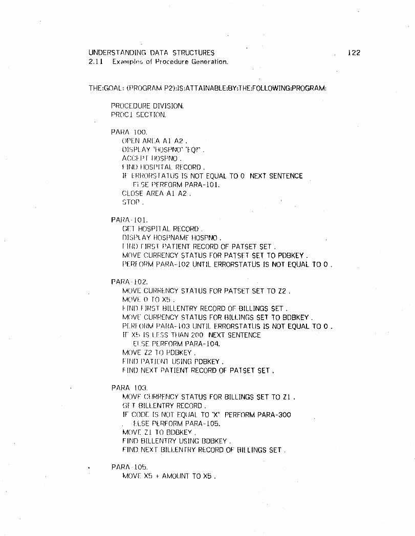
UNDERSTANDING DATA SIRUCTURES 122
2.1 l Exampl_,,,sof Procedure Generation.
THE:GOAL: (PROGRAM P2):IS:ATTAINABLE:BY:THE:FOLLOWING:PROGRAM:
PROCEDURE DIVISION.PROCI SECTION.
PARA- 100.()PENAREA A I A2.
DISPLAY 'IIOSPNO' 'EQ?".ACCEPT HOSPNO.F]ND I IOSPITAL RECORD.
IF EITRORSTATUSIS NOT EQUALTO 0 NEXTSENTENCEELSE PERFORMPARA-IOL.
(;LOSE AREA A1 A2.SrOP .
PARA 10 t.GEl HOSPIIAL RECORD.DISPI_AYHOSPNAMEHOSPNO.FIN[) FIRST PAI-IENT RECORDOF PATSET SET.MOVE CURRENCYSTATUS FORPATSET SET TO PDBKEY.PERFORMPARA-]02 UNTIL ERRORSTATUSIS NOT EQUALTO 0.
PARA- I02.MOVE CURRENCYSTATUS FORPATSET SET TO Z2.MOVE O TO X5.f-IN[) F:IRST BILLEN]RY RECORDOF BILLINGS SET.MOVE CURRENCYSTATUS FORBILLINGS SET TO BDBKEY.P[ RFORMPARA-103 UNTIl_ERRORSTATIJSIS NOT EQUALTO O.IF X5 IS LESS rl-4AN200 NEXTSENTENCE
ELSE PERFORM PARA-104.MOVE Z2 TO PDBKEY.FIN()PATIENT USINGPDBKEY.FIN[) NEXT PATIENT RECORDOF PATSET SET .
PARA- 103.MOVE CURRENCYSTATUS FORBILLINGS SET TO ZI .Gt!I BILl.ENTRY RECORD.IF CODE IS NOT EQUALTO 'X' PERFORMPARA-300
ELSE PERFORMPARA-I05.MOVE Zt 10 BDBKEY.FIN[] BILLENTRY USING BDBKEY.FIND NEXT BILl_ENTRYRECORDOF BILLINGS SET.
• PARA -.105.MOVE X5 + AMOUNT TO X5.

UNDERSIANDING DATA STRUCTURES t232,1 ! E×amples of Procedure Generation,
PARA--t04.GEl PATIENT RECORD.DISPLAY PATNAME PATNO,
PROC3 SECTION,PARA -300.
IF CODE IS NOT EQUALTO 'Z' NEXTSENTENCEELSE PERFORMPARA-301,
PARA_301.MOVE X5 + AMOUNT TO X5,
Figure 2-3J. Program P2,

UNDERSTANDING DATA STRUCTURES 1242.11 Example_, of Procedure Generation.
ENTER PROGRAM NAME P3
READ DSK:'_.TEEtM_&EY_R!::CC!RD{M.AJ£1)*_SALESMANCO_.N_[]I()NS FOR RETRIEVAL*ANY
I:_'RIMARYRE('ORDA._*-()RD[RC"(_)N[)I_II!)N,,SIF_()_RRETRIEVAL*(OR[)-II]ATEGE RUNTIME)*(ORD-I)AI-EI._ERUNTIME), NIL
,NILITEMS OR STAIS TO BE DISPLAYED,MAN- NAME:
*_DIST-NO*_AVE:
_PR]M_AR_.Y.._REC___OR__DD*ORDER
GO_I',!D!TI.Q_!.s_E.oER._ET_R_RIEVA__L*NIL
._*TOTPRIMARY RECORD,Er,J[RY
90[:_II)[!}ION__SSEDE RETRIEVAL*NIL
ITEMS C)RSTATS FOR TOT,_.XC(:)ST,NIL
*_COUNI-P_[_IM&[__Y_RE__COR___DLCOU_Q_M.N__*ENI RYCONI]ItIONS FORRETRIEVAL*Nil_
_*_Nit_*NIL
Figure 2-32. Query P3: "For those salesmen who have any orders with anorder datr, that falls between two dates specified at run-time, display his name,districl numl)er, the average cost per order, .and the average number of itemsper Order."

UNDERSTANDING DATA STRUCTURES , t252. l [ Examples of Procedure Generation.
THE:GOAL: (PROGRAMP3):IS:ATTAINABLE:BY:THE:FOLLOWING:PROGRAM:
PROC:E[)t JREDIVISION.PRO(;1 SECTIONPARA- 100.
OPEN AREA MAINA .FIN[) FIRST SALESMAN RECORDOF MAINA AREA.MOVE CLJRRENCYSTATUS FORMAINA AREA TO KEY2.PERFORMPARA-101 UNTIL ERRORSTATUSIS NOT EQUALTO 0.CI_OSEAREA MAINA.SlOP.
PARA 10[,MOVE CIIRRENCYSTATUS FORMA[NA AREA TO Z5 .M()VE 0 TOXI.FIND fIRST ORDERRECORDOF SALES SET.MOVE CURRENCYSTATUS FOR SALESSET TO KEY3.PERFORMPARA-102 UNTIL
( ERROP,STA-[US IS NOT EQUALTO 0 ) OR( X l IS EQUALTO _ ).
IF X] 1S NO] EQUALTO I NEXTSENTENCEtiLSE PERFORMPARA-103.
MOVF:Z5 10 KEY2.rIND SALESMAN USINGKEY2.F-INDNEXT SALESMAN RECORDOF MAINA AREA.
PARA- 102.MOVE CURRENCYSTATUS FORSALES SET TO Zt .IFi X]3 IS NOT EQUALTO HIGH-VALUES NEXTSENTENCE
ElSE PERFORMPARA-104.(;I-:[ ORDERRECORDIF Ot_I)-DAIE IS LESS THAN X;3 NEXTSENTENCE
ElSE PERFORMPARA-t05.MOVE:Z] lC) KEY3 .I IN[) ORDERUSINGKEY3 .FIND NEXT ORDERRECORDOF SALESSET .
PARA 104.DISPLAY 'ORD-DATE' 'GE?' .ACC[PT Xl3 .
PARA .-10F_.
IF X I4 IS NOT EQUAL10 HIGH-VALUES NEXT SENTENCEELSE PERFORMPARA-106.
IF ORD-DATE IS GREATERTHAN X14 NEXT SENTENCEELSE PERFORMPARA-107.
PARA- t 06.DISPLAY 'ORD-DATE' _LE?'.ACCEPT X 1-'1.
PARA-I07,

UNDERSTANDING DATA STRUCTURES 1262.11 Examples of Procedure Generation.
MOVE 1 TOXI.PARA- ! 03.
GET SALESMAN RECORD.FIND OWNERRECORDOF SALESMENSET.GEl DISTRICT-HDR RECORD.MOVE 0 IO X4 .MOVEO lOX7.MOVE O TOXJl .FIND FIRS: ORDERRECORDOF SALES SET.MOVE CURRENCYSTATUS FORSALES SET TO KEY3 .PERFORMPARA-! 10 UNTIL ERRORSTATUSIS NOT EQUALTO O .MOVE X7 DIVIDED BY X4 TO X7.MOVE X1 1 DIVIDED BY X4 TO X11 .DISPLAY MAN-NAME DIST-NO X7 Xl 1 .
PARA- J 10.MOVE CURRENCYSTATUS FORSALES SET TO Z4.MOVE X4 + ! TO XZl.MOVE O TOX6.FIND FIRST ENTRYRECORDOF ORDERLISTSET.MOVE CURRENCYSTATUS FORORDERLISTSET TO KEY6.PERFORM PARA-I I I UNTILERRORSTATUS IS NOT EQUAL TO 0.MOVE X7 + X6 TO X7.MOVE 0 TOXIO.FIND FIRST ENTRYRECORDOF ORDERLISTSET.MOVE CURRENCYSTATUS FORORDERLISTSET TO KEY6.PERFORMPARA-112 UNTIL ERRORSTATUSiS NOT EQUAL TO 0.MOVEXII +XIO TOXll .MOVE Z4 TO KEY3.FIND ORDERUSINGKEY3.FIND NEXT ORDERRECORDOF SALES SET.
PARA-I II,MOVE CURRENCY STATUS FOR ORDERLIST SET TO Z2,(;El"ENqRY RECORD.
MOVE X6 4 XCOST TO X6.MOVE Z2 TO KEY6.FIND ENTRYUSINGKEY6.FIND NEXT ENTRYRECORDOF ORDERLISTSET.
PARA- 1/ 2.MOVE CURRENCYSTATUS FORORDERLISTSET TO Z3.MOVE XIO + 1 TOXIO.MOVE Z3 10 KEY6.FIND ENTRYUSINGKEY6 •FIND NEXT ENTRYRECORDOF ORDERLISTSET .
Figure 2-33. Program P3.

UNDERSTANDING DATA STRUCTURES ]272./I Examples of Procedure Generation.
ENTER PROGRAMNAME P4
READ P__S__:'ZTPRIMARY RECORDMA_*CUSTOMERCONDITIONS FOR RETRiEVAl..,_(COUNTG]- 3)
PRIMARY RECORD,ORDERCONDiTiONS FOR RETRIEVAL
*-(ORD-DATE LT RUNTIME)*-(SHIP-DATE EQ O),NIL
*NIL|TEMS OR SI'ATS TO BE DISPLAYED
,_CUST-NAME*_ONE
FR!MAR_YRECORD{_.ON__NE./,SALESMANC_OND_I_TIO__NSF_OR_RETRIEVAL*Nil_
ITEMS OR STATS TO BE DISPLAYED
,_DIST-NO,MAN-NAME,NIL
,_CONDCONDITIONS FOR RETRIEVAL,(TOT GT lO000)
PRIMARY RECORD,ENTRYCONDITIONS FORRETRIEVAL,NIL
I-[EMS ()RSTATS FORTO]"*X C'OST*NIL
*NILITEMS OR STATS TO BE DISPLAYED__'IMPORIANT'*'CUSTOMER!'
" *NIL"_ ,NIL#
Figure 2-34. Query P4: "For those customers who have outstanding ordersplaced prior to a run-time date, display the customer's name and the name anddistrict number of a salesmen who services lha| customer. If [he total value of
that customer's orders exceeds 810,000, display the words 'imporlantcustomer'."
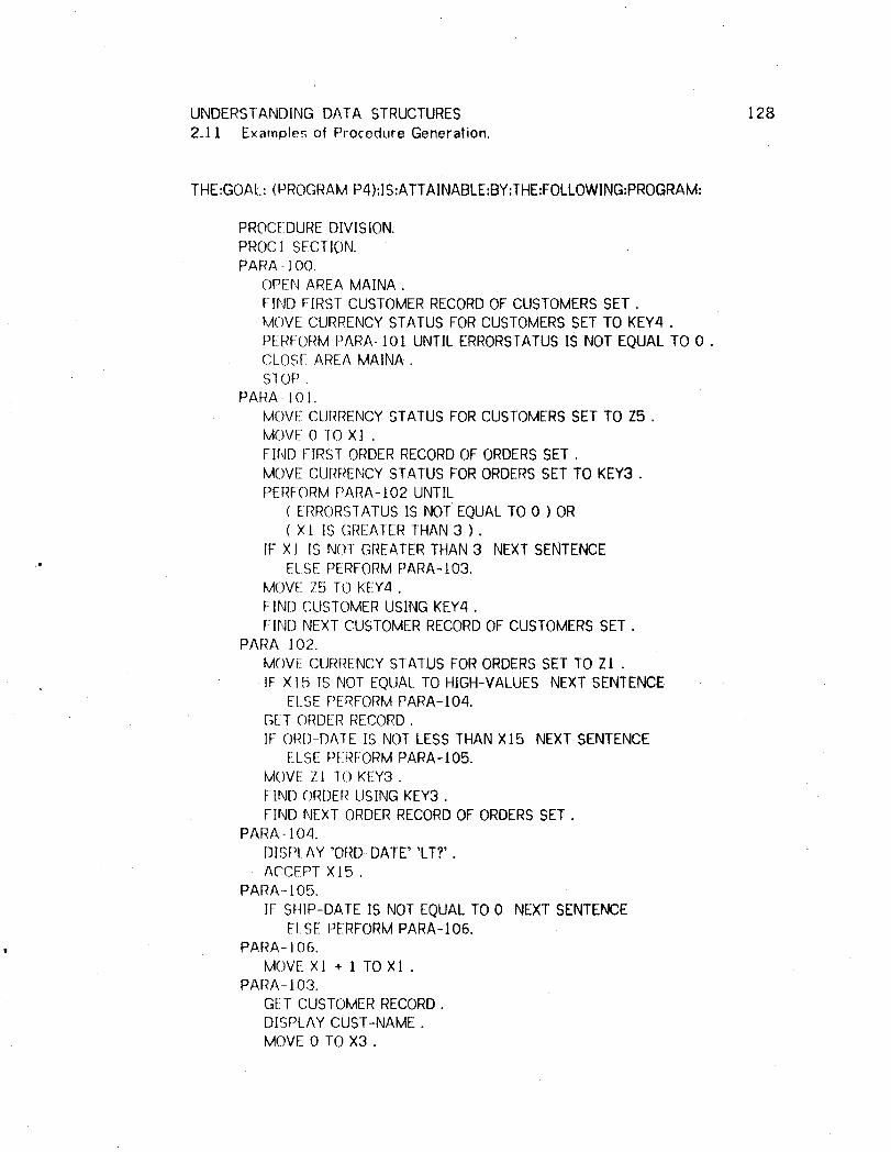
UNDERSTANDING DATA STRUCTURES 128
2.]. 1 Examples of Procedure Generation.
THE:GOAL: (PROGRAM P4):IS:ATTAINABLE:BY:THE:FOLLOWlNG:PROGRAM:
PROCEDUREDIVISION,PROC1 SECTION. I 'PARA - J00.
OPEN AREA MAINA.FIND FIRST CUSTOMERRECORDOF CUSTOMERSSET.MOVE CURRENCYSTATUS FORCUSTOMERSSET TO KEY4.PERFORMPARA-IOI UNTIL ERRORSTATUSIS NOT EQUALTO 0.CLOSE AREA MAINA.SI OP ,
PARA 10].MOVE CURRENCYSTATUS FORCUSTOMERSSET TO Z5 .MOVE O-[OXl.FIND FIRST ORDERRECORDOF ORDERSSET .MOVE CURRENCYSTATUS FORORDERSSET TO KEY3 .PERFORMPARA-/02 UNTIL
( ERRORSTATUSIS NOT EQUALTO 0 ) OR( X! IS GREATERTHAN 3 ) .
IF XJ IS NOT GREATERTHAN 3 NEXTSENTENCE'" ELSE PERFORMPARA-t03.
MOVE Z5 TO KEY4 .FIND CUSTOMERUSINGKEY4.FIND NEXT CUSTOMERRECORDOF CUSTOMERSSET.
PARA-]02.MOVE CURRENCYSTATUS FORORDERSSET TO Zi .
, IF X]5 IS NOT EQUALTO HIGH-VALUES NEXT SENTENCEELSE PERFORMPARA-104.
GET ORDERRECORD.IF ORD-DAIE IS NOT LESS THAN X15 NEXT SENTENCE
ELSE PERFORMPARA-105.MOVE ZI T(T)KEY3.FIND ORDERUSING KEY3.FIND NEXTORDERRECORDOF ORDERSSET.
PARA- ! 04.DISPLAY 'ORD DATE' 'LT?'.A('CEPT X15.
PARA- ! 05.IF St4[P-DATE IS NOT EQUALTO 0 NEXTSENTENCE
ELSE PERFORMPARA-I06.PARA- 106.
MOVE XI + ] TOX! .PARA- 103.
GET CUSTOMERRECORD.DISPLAY CUST-NAME.MOVE 0 TOX3.

UNDERSTANDING DATA STRUCTURES 129
2.1 i Examples of Procedure Generation.
FIND FIRST ORDERRECORDOFORDERSSET .MOVE CURRENCYSTATUS FORORDERSSET TO KEY3 .PERFORMPARA-I07 UNTIL ( ERRORSTATUSIS NOT EQUALTO 0 ) OR
( X3 IS EQUALTO 1 ).MOVEO TOXll ,FIND FIRST ORDERRECORDOFORDERSSET.MOVE CURRENCYSTATUS FORORDERSSET TO KEY3.
PERFORMPARA-110 UNTIL ERRORSTATUSIS NOT EQUAL TO 0 ,IF Xt I IS NOT GREATERTHAN tO000 NEXTSENTENCE
ELSE PERFORMPARA-I 1/.PARA-107.
MOVE CURRENCYSTA[US FORORDERSSET TO Z2.FIND OWNERRECORDOF SALESSET.FIND OWNERRECORDOF SALESMENSET,[-_EI DISTRICT-HDR RECORD.GEl SALESMAN RECORD.[]ISPLAY DIST--NOMAN-NAME.MOVE I TO X3.MOVE Z2 10 KEY3 .FIND ORDERUSING KEY3 .FIND NEXTORDERRECORDOF ORDERSSET .
PARA--/]0.
MOVE CURRENCYSTATUS FORORDERSSET TO Z4 .FIN[) FIRST ENTRYRECORDOF ORDERLISTSET .MOVE CURRENCYSTATUS FORORDERLISTSET TO KEY6 .PERFORMPARA-I 12 UNTIL ERRORSTATUSIS NOT EQUALTO 0 .MOVE Z4 [0 KEY3 .F]NI) ORDERUSING KEY3 .
It FIND NEXTORDERRECORDOF ORDERSSET .PARA- l 12.
MOVE CURRENCYSTATUS FORORDERLISTSET TO Z3 ,GET ENTRY RECORD.MOVE X][ +XCOST TOXI1 .MOVE Z3 TO KEY6.FIND ENTRYUSING KEY6.FIND NEXT ENTRYRECORDOFORDERLISTSET.
PARA- 1 11.DISPLAY 'IMPORTANT' 'CUSTOMER!'.
Figure 2-35. Program P4.
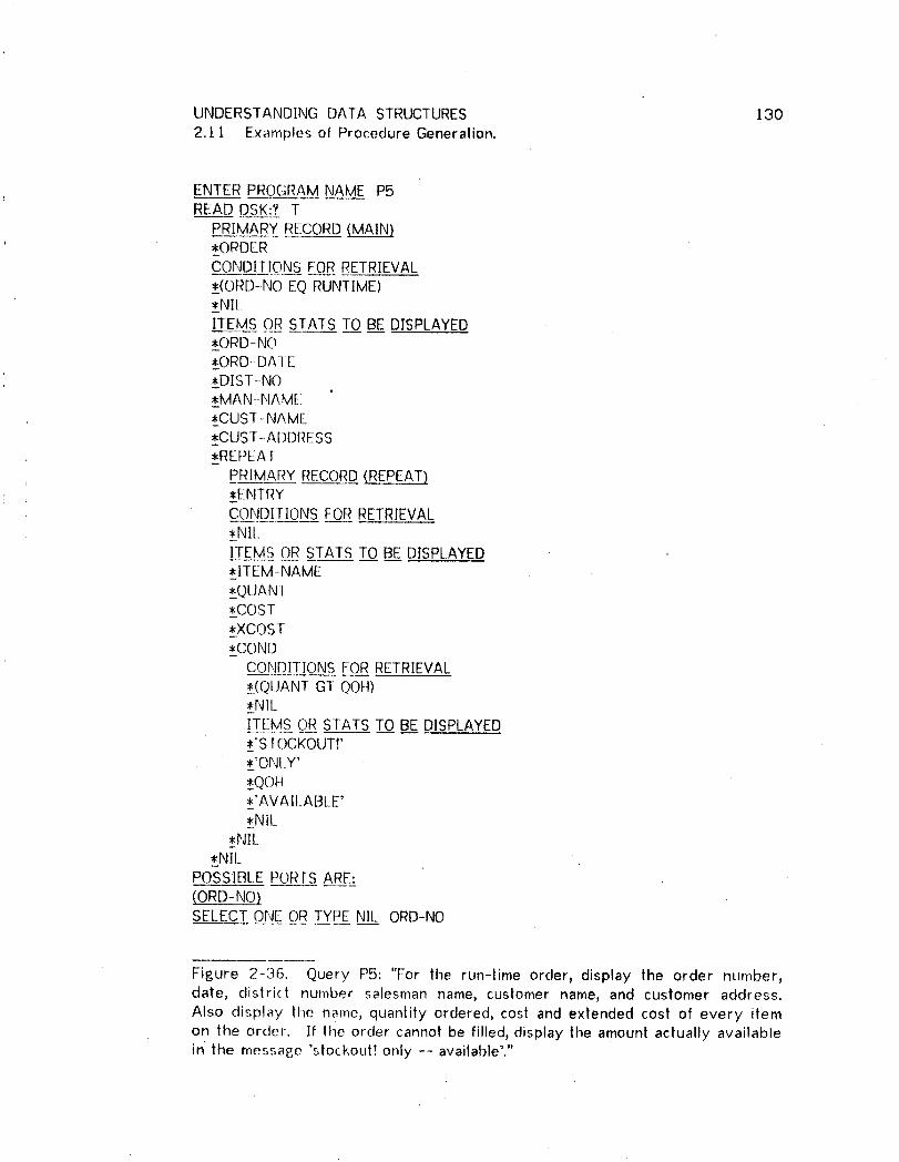
UNDERSTANDING DATA STRUCTURES 1302. t 1 Examples of ProCedure Generation.
ENTER PROGRAMNAME P5READ DSK:? T
PRIMARY RECORD.MAL__ORDERCONDITIONS FOR RETRIEVAL__(ORD-NOEQ RUNTIME)*NILITEMS OR SfAIS 10 BE DISPLAYED__ORD-NO__ORD-DA]E__DIST-NO__MAN-NAME{CUST-NAME__CUST-ADDRESS_REPEAT
PRIMARY RECORD(REPEAT)*EN-FRY
CONDII-IONSFOR RETRIEVAL,NILITEMS OR STATS TO BE DISPLAYED{ITEM-NAME_QUANT_COST,_XCC)ST,CONDCONDITIONS FOR RETRIEVAL
_(OUANT GT QOH)#NILITEMS OR STATS TO BE DISPLAYED_'SIOCKOUT! _{'ONLY'_QC)H{_AVAI[_ABLE',NiL
,_NIL_NII_
POSSIBLE PORTSARE:
(ORD-NO)SELECT ONE OR TYPE NIL ORD-NO
Figure 2-36. Query PS: "For tile run-time order, display the order number,date, distri(t nu'mber salesman name, customer name, and customer address.Also display the name, quantity ordered, cost and extended cost of every itemon the order. If the order cannot be filled, display the amount actually availablein' the message 'stockouH only -- available'."

UNDERSTANDING DATA STRUCTURES 13I2,1 l E×amples of Procedure Generation,
THE:GOAL: (PROGRAMP5):IS:ATTAINABLE:BY:THE:FOLLOWING:PROGRAM:
PROCEDUREDIVISION.PROCI SECTION.PARA- 100.
()PEN AREA MAINA .DISPLAY 'ORD-NO' 'EQ?' .ACCEPT ORD-NO.FIN[) ORDERRECORD.
IF ERRORSTATUSIS NOTEQUALTO 0 NEXT SENTENCEELSE PERFORMPARA-IO[.
CI.OSEAREA MAINA .S1OP .
PARA- ] 01.[;El ORDERRECORD.FIND OWNERRECORDOF SALES SET +FIND OWNERRECORDOF SALESMENSET .GET DIS_fRICT-HDRRECORD.GEt SALESMAN RECORD.FIND OWNERRECORDOF ORDERSSET .GET CUSTOMERRECORD.DISPLAY ORD-NO ORD-DATEDIST-NO MAN-NAME CUST-NAME
CUST-ADDRESS.FIND FIRST ENTRYRECORDOF ORDERLISTSET .MOVE C[JRRENCYSTATUS FORORDERLISTSET TO KEY6 .PERFORMPARA-t02 UNTIL ERRORSTATUSIS NOT EQUAL TO 0 .
PARA- I O2.MOVE CURRENCYSTATUS FORORDERLISTSET TO Z! .FIND OWNERRECORDOF SOLD SET.GET INVENTORYRECORD.GET ENTRYRECORD.
DISPLAY ITEM-NAME QUANTCOSTXCOST.GET INVENTORYRECORD.GET ENTRYRECORD.
IF QUANT IS NOT GREATERTHAN QOH NEXT SENTENCEELSE PERFC)RMPARA-I03.
MOVE Z1 TO KEY6 .FIND ENTRY USINGKEY6 .FIND NEXT ENTRYRECORDOF ORDERLISTSET .
PARA- 103.
DISPLAY 'STOCKOUTF'ONLY' QOH'AVAILABLE'.
Figure 2-37. Program P5.

UNDERSTANDING DATA STRUCTURES 1322./l Examples of Procedure Generation.
ENTER _P__OG_[_A__MNAME P6READ D_S'_K;ZT
PRIMARY RECORDMA_*_DOCTORCONDITIONS FOR RETRIEVAL__(DOCNOEQ R[JNTIME)*NIL
, ITEMS OR STATS TO BE DISPLAYED__DOCNO•_DOCI'4AME*REPEAT
PRIMARY RECORD(REPEAT),F_AIIENTCONDITIONS FOR RETRIEVAL*NIl
I_:[:EMSO_R_STAT_S_T__.OBE DISPLAYED*_PAINO*PAl 1'4AME*_REPEAT
PRIMARY RECORD(REPEAT)__DOCI:OR
CONDIIIONS FOR RETRIEVAL*NIL_ITEMS OR STATS TO BE DISPLAYED_I]OCNO__DOCNAME*=_NIL
*NIL*Nil_.
POSSIBI_EPORIS ARE:
DSELECT ONE OR TYPE NIL DOCNO
Figure 2-38. Query P6:"Display the name and number, of a doctor specified atrun-time. Also display the name and number of all of his patients, and for eachpatient display the name and number of all of his doctors."

UNDERSTANDING DATA STRUCTURES ]332.1 t Examples of Procedure Generation.
THE:GOAL: (PROGRAMP6):IS:ATTAINABLE:BY:THE:FOLLOWlNG:PROGRAM:
PROCEDURE DIVISION.PROC 1 SECTION.
PARA- 100.OPEN AREA AI A2 .
DISPLAY 'DOCNO''EQ?' .ACCEPT DOCNO,FIND DocroR RECORD.
IF ERRORSTATUSIS NOT EQUALTO 0 NEXT SENTENCEELSE PERFORMPARA-IOI.
CLOSEAREA AI A2 .STOP .
PARA-IOI.
(;El"DOCTOR RECORD.DISPLAY DOCNO DOCNAME.FIND FIRST TREATMENT RECORD OF TREATING SET.MOVE CURRENCY STATUS FOR TREATING SET TO TDBKEY.
PERFORM PARA-I02 UNTIL ERRORSTATUS ISNOT EQUAL TO 0 .
PARA- 102.
MOVE CURRENCYSTATUS FORTREATING SET TO Z2 .FIND (_)WNERRFCORDOF'TREATMENTSSET.(BETPATIENT RECORD.DISPLAY PATNO PATNAME ,FIND FIRS[ IREATMENT RECORDOF TREATMENTSSET .MOVE C.IJRRENCYSTATUS FORTREATMENTSSET TO TDBKEY .PERFORMPARA-103 UNTIL ERRORSTATUSIS NOT EQUALTO 0 .MOVE Z2 TO TDBKEY,FIND TREA-[MENT USINGTDBKEY.FIND NEXT TREATMENTRECORDOF TREATING SET .
PARA- t 03.MOVE CURRENCYSTATUS FORTREATMENTSSET TO Z1.[IND OWNERRECORDOF TREATING SET.GEl D(.)CTORRECORD. ..DISPLAY DOCNODOCNAME.MOVE ZI TO TDBKEY.FIND TREATMENT USINGTDBKEY.FIND NEXT TREATMENTRECORDOF TREATMENTSSET.
Figure 2-39. Program P6.

UNDERSTANDING DATA STRUCTURES /34
3 DESIGN OF DATA STRUCTURES.
3.1 [ntrodllction.
9.1.1 Functional
The Data Base Task Group (DBTG) [CODASYL 197J.a] describes a new job
function called Data Base Administrator(DBA):
"He will:
Employ a data structure(s) that models the business or
problem... Assign names in such a manner as to assuretheir uniqueness. Select search strategies..."
In other words, the DBA designs data structures. Although a structure can be
defined e×istentiall_ as sciggested by DBTG, "...models the business...", .such a
data base may conlain information which will never be used. In addition, the
quality of such a data base is heavily dependent on the DBA's ability to
recognize the environment that must be captured (modeled)in the data base. It
may be much better to define a structure functionally, e.g. based on
anticipated information demands that the data base must satisfy.
|n this chapter ] will first describe how the DBA can utilize the retrieval
program generator from the previous chapter as an aid in functional data base
design. Fdllowing this, ] will describe an automatic data base structure
designer, hereafter called the designer_ automatic designer, or machine designer,
that can design a satisfactory data base structure for a set of information
qoeries. Since this designer uses only a set of anlicipaied queries as input, the
ouput is a functional design rather than an existential design.
UNDERSTANI'.)ING DATA STRUCTURES 1353. t Introduclion.
3.1.2 Relalion to p__E£grammer.
The automatic data base structure designer and the automatic Information
retrieval programmer of Chapter 2 form a package. Both programs use the
HI-IQ query language. The aulomatic designer generates a data base structure
that can be used as a data base description for the automatic programmer.
The programs are also similar because both translate from relational
descriptions to access path descriptions.
3.1.3 Limitations.
This chapter is concerned wilh tile design of data structures. Data structure
design is only part of the overall problem of data base design. Some other
design issues, not considered here, are decisions regarding data types, data
base subdivision into areas, storage media, record ordering, record selection,
and data protection. Also, data characteristics such as relative volumes,
volatility of data, etc., that may affect data base structure design decisions have
been ignored in this chapter. Ignoring these design issues and data
characteristics will never result in data structures that are inconsistent with the
set of queries, but it may lead to the design of inefficient data structures.
The automatic structure designer determines record conteht and record
relationships (sets) and also suggests inversions and items to be used as
calculated keys. The output of the automatic designer is not equivalent to a
UNDERSrAND]NG DATA STRUCTURES 1363.1 Introduction.
complete DDL [CODASYL 1971a] description of a data base. Many stalements
necessary in a complete DDL description affecting record ordering, set ordering,
selection mode, da|a privacy, data pictures_ area conlen|j e|c._ are not generated
by Ihe aulomatic data base structure designer.

UNDERSTANDING DATA STRUCTURES 137
3.2 Use of the Prop_rammer.
The retrieval program generator described in the previous chap!er can be used
by the DI3A during the data base design process. Since the program generator
is data-free, program generation is solely a function of the data base description
and the query. This "data-freeness" is an important difference between
generalized inlerpreters and automatic programming. It is one of my reasons
for using automatic programming rather than designing a generalized
interpreter. (See section 2.3.) Data-freeness also permits use of the
programmer during the design phase when a data base is not yet available.
Figure 3-! illustrates the use of a programmer(human or machine) 1o aid in data
structure design. The user communicates his needs (in the form of a query) to
the programmer, the programmer obtains the proposed data base structure from
the DBA and attempts to write a program. If the programmer is unsuccessful he
communicates this to the DBA. Otherwise, he provides the DBA with the
program. In eilher case the DBA can judge the validity of the proposed data
base structure and make appropriate modifications. If any modifications are
made, then the programmer tries again to create a prog.ram until a cycle is
completed in which no data base structure modifications occur.

UNDERSTANDING DATA STRUCTURES 138
3.2 Use of the Programmer.
_ QUERY _IROGRAMMER ._.... I'---'-- "1QUERY .... _ I"DATABASE
J [............... j ]STRUCTURE
IDATABASEIADMINISTRATOR
Figure 3--}.. A simple user - programmer - DBA system.
This same process is then repeated for another query until all queries have
been translated to satisfactory programs. Upon completion of this time
consuming process the DBA can be reasonably confident that the proposed
structure is sufficient for user needs. Note that the data base itself is not
'involved in this, system. (Another feedback loop in the user-programmer-DBA
system is clo._,ed after the data base has been created and the user obtains the
results of lhe execution of the programs associated with his needs. At this
point other adjustments become necessary, usually resulting in restructuring,
discussed in Chapter 4.)
This technique is laborious and random, especially for the DBA. To make the
process feasible, other lines of communication are necessary between the
programmer and the DBA (to report causes of failure) and between the users
UNDERSTANDING DATA STRUCTURES 1393.2 Use of the Programmer.
and the DBA (for naming conventions). An algorithm for finding the initial data
base structure must also be specified.
Human programmers cannot be used for this method of design because they
would take too long and the cost of writing the programs for testing each design
would be Ioo high. This restriction does not apply to the machine programmer
discussed in Chapter 2. However, [ have not designed a data base structure
using the automatic programmer in the process described above, but
consideration of this process led me to automate the data base structure design
process in its entirety. This is the subject of the next section.
UNDERSTANDING DATA STRUCTURES 140
3.3 Automatic Data Structure Design.
3.3.1 Overview.
The implemented designer generates a data structure design in one pass as
illustrated in Figure 3-2. This system is .no.j[ iterative as was the process
discussed for Figure 3-1.
Structure design requires two phases. |n the first phase all queries are
scanned, and for each query a se| of assertions is generated that describe the
structural concepts of the data base necessary for the query. A particular
assertion is a constraint on lhe design, but there may be many designs which
satisfy thai assertion. The second phase tries to find a design that satisfies all
of the assertions.
The two phases are illustrated in Figure 3-2 as follows:
(a) Generate assertions
(first three steps in Figure 3-2)
(b) Record and network construction
(la-._| four steps in Figure 3-2)
The program for phase 1 is almost identical Io the Request Handler described in
Chapter Two. Since the HI-IQ language is used by both the designer and the
program Poenerator, the query interpreter wilt be the same for both.
Furthermore, each assertion made in the first design phase corresponds to a
structural concept |hal the program generator would require in the defined data

UNDERSTANDING DATA STRUCTURES 14l
3.3 Automatic Data Structure Design.
structure.
The designer permits interruption while generating assertions. This allows a
structure to be designed from a subset of tile queries with a later continuation
of the design process from the point of interruption. The DBA can therefore
use the system to quickly determine the impact on the data base structure of a
particular subset of queries.
The actual design process occurs in the fourth and fifth boxes of the chart in
Figure 3-2. In these steps the system tries to derive a network structure
design thai is consistent with the assertions.
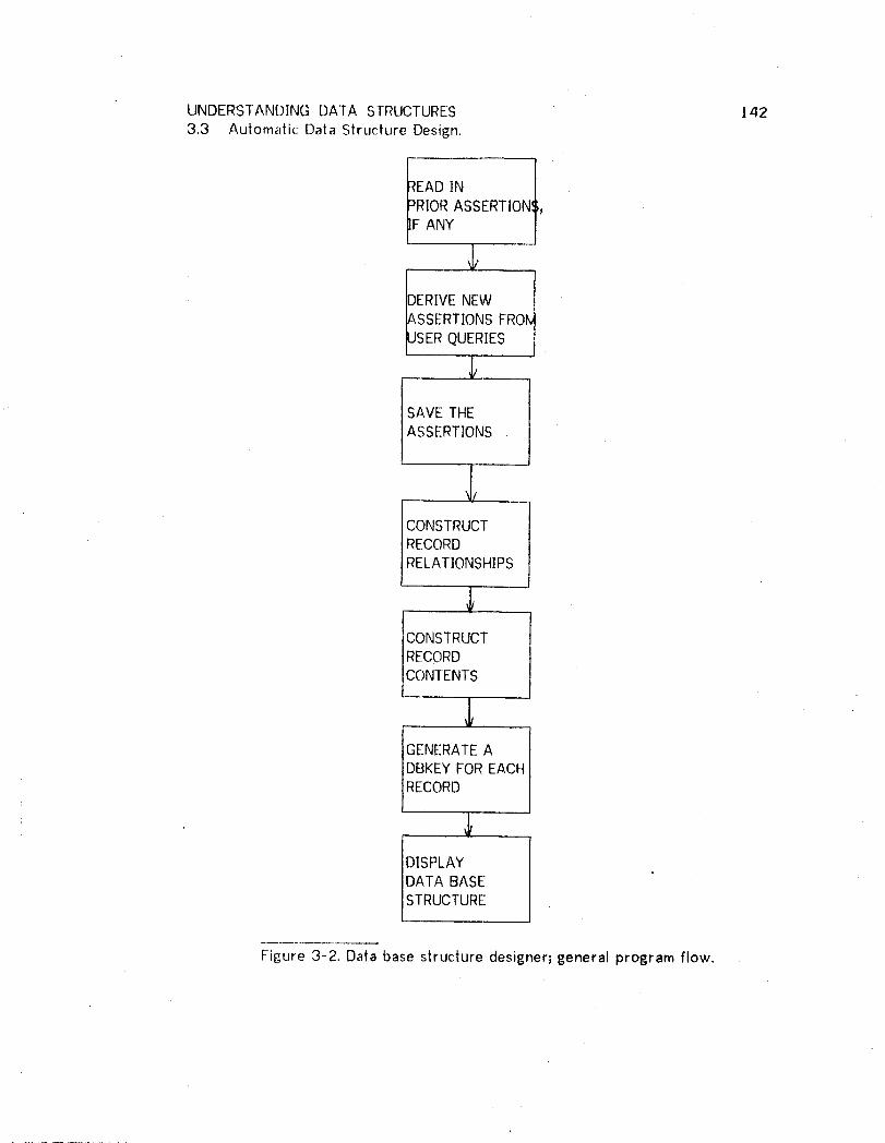
UNDERSTANDING DATA STRUCTURES 1423.3 Automatic Data Structure Design.
ANY J
_USERQUERIES J
_ _SAVETHEASSERTIONS
J,CONSTRUCTRECORDRELATIONSHIPS
CONSTRUCTRECORD
CONTENTS
GENERATE ADBKEY FOR EACHRECORD
DISPLAYDATA BASESTRUCTURE
Figure 3-2. Data base structure designeq general program flow.

UNDERSTANDING DATA STRUCTURES 143
3.4 DefininE ltem.Names.
Since several users may be generating the queries, there are two problems
related to ilem (attribute) names. Different users might use the same name for
different attributes or they might use different names when referring to the
same attribute.
In addition, misspelling can occur. A design system has difficulty with these
problems because it has no external corroboration for verification of names.
There are several ways of handling this problem. ! have chosen the last of
these approaches:
a) Indicate the caveat: Errors in data base structure mayrestdt from errors in naming items and records or from theuse of identical names for different items and records.
b) Interactive corroboration: Provide for interaction
between the machine designer and time DBA whenever a nameis encountered for the first lime or in any other situationswhere errors might go undetected without additionalcorroboration.
c) Definitive corroboration: Require a definition list ofnames prior to beginning the design process,

UNDERSTANDING DATA STRUCTURES 144
3.5 Generatin£., Assertions.
The automatic designer first generates assertions regarding the data base
structure that is to be designed. These assertions are used to direct and
constrain the eventual design process.
The asserlions made in this phase concern item and record relationships.
Although lhe query may contain commands such as COUNT, ANY, REPEAT, elc._
these commands are ignored except to note that the record mentioned in the
context of such a command must be hierarchically below the record mentioned
prior to that command. Similarly, the designer makes no distinction between the
"COND]T]ONS FOR RETRIEVAL" and the "]TEMS OR STATS" inputs for each
record, Both inputs are simply scanned for'names which are not commands.
These names are then checked against the master name list and if found,
assumed to be ilems,
That the designer ignores these commands should give some indication of its
limitations. A better system would consider some of the aforementioned usapoes
to (for example) design an ordered set.
Assertions are made wherever the programmer would have checked for the
presence of certain relationships in the defined structure. There are only three
such assertions. fhese are listed along with their meaninF, s in Figure 3-3.
Succeeding paragraphs will discuss the generation of these assertions; it should
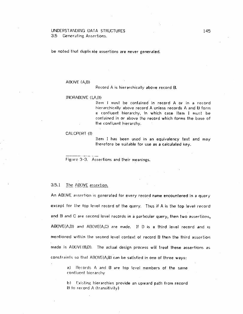
UNDERSTANDING DATA STRUCTURES 145
3.5 Generating Assertions.
be noted that duplicate assertions are never generated.
ABOVE (A,B)
Record A is hierarchically above record B.
INORABOVE (I,A,B)Item I must be contained in record A or in a record
hierarchically above record A unless records A and B forma confluent hierarchy, in which case item | must becontained in or above the record which forms the base of
the confluent hierarchy.
CALCPORT (l)
Item I has been used in an equivalency test and maytherefore be suitable for use as a calculated key.
Figure 3-3. Assertions and their meanings.
3.5.1 The ABOVE assertion.
An ABOVE assertion is generaled for every record name encountered in a query
except for the top level record of the query. Thus if A is the top level record
and B and C are second level records in a particular query, then two assertions,
ABOVE(A,B) and ABOVE(A,C) are made. If D is a third level record and is
mentioned within the second level context of record B then the third assertion
made is ABOVE(B,D). The actual design process will treat these assertions as
constraints so thai ABOVE(A,B) can be satisfied in one of three ways:
a) Records A and B are top level members of the sameconfluent hierarchy
b) Exi.'4ing hierarchies provide an upward path from recordB to re{ord A (transitivity)

UNDERSTANDING DATA STRUCTURES 146
3.5 Gener alinE, Assertions.
c) Records A and B are contained in a set with A as ownerand B as member.
3.5.2 The ]NORABOVE assertion.
Items can be menlioned in a query both as intended for display or for use in a
conditional test. In either case they are always mentioned within the context of
a particular record. The principle of downward attribute migration lets the
system conclude lhal the items must be physically located within or
hierarchically above tile conlext record.
For those unfamiliar with the concept of confluent hierarchies, an example of
such a structure is given on the left in Figure 3-4. The TREATMENT record is
the base record of this structure because it is hierarchically below all other
records. This structure is also discussed in section 1.3, Figure I-3. Since any
of the records included in a confluent hierarchy can occur hierarchically above
any of the other records, such a structure can be processed "both ways". The
query context determines which way the confluent hierarchy is being processed.
It is for this reason that the INORABOVE assertion includes a description of the
query context, described with records A and B.
Figure 3-4 illustrates the effect of query context. It is perfectly legal for a
query to refer Io the unique DIAGNOSIS associated with a particular PATIENT
record if the query context is lhe DOCTOR-PATIENT hierarchy, even though the
actual data base structure has the DIAGNOSIS item below the PATIENT record.

UNDERSTANDING DATA STRUCTURES 147
3.5 Generating Assertions.
This is legal since the relationship can be reversed because of the confluency of
the DOCTOR and PATIENT records. Because of this confluent hierarchy it is
possible to associate many DIAGNOSIS records with a PATIENT in one context
and to associate a unique DIAGNOSIS in another context.
Since it is not known at the time the assertions are made if a particular context
hierarchy will be part of a confluent hierarchy, the system must indicate the
hierarchical context, not just the context record, when describinp_ the use of a
particular item. Thus, for the previous example, the assertion would be:
INORABOVE(DIAGNOSIS,PATIENT,DOCTOR). To the second phase, this assertion
will mean "DIAGNOSIS must be contained within or above the PATIENT record
unless the PAItENT and DOCTOR records exist in a confluent hierarchy in which
case the DIAGNOSIS item must be contained within or above the lowest or base
record of the confhJent hierarchy."
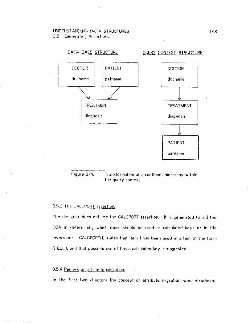
UNDERSTANDING DATA STRUCTURES 1483.5 Generating Assertions.
DATA BASE STRUCTURE _CONTEXT STRUCTURE
/
DOCTOR PATIENT / DOCTOR
docname patname J docname
I TREAfMENT 1 TREATMENTdiagnosis diagnosis
PATIENT
patname
Figure 3-4. Transformation of a confluent hierarchy withinthe query context.
3.5.3 The CALCPORT assertion.
The designer does not use the CALCPORTassertion. It is generated to aid the
DBA in determining which items should be used as calculated .keys or in file
inversions. CALCPORT(I) states that item ] has been used in a test of the form
(! EQ...),and that possible use of ! as a calculated key is suggested.
3.5.4 Remark on attribute migration.
In the first two chapters the concept of attribute migration was introduced.

UNDERSTANDING DATA STRUCTURES 149
3.5 Generating Assertions.
Since the data base structure designer ignores all statistical commands it need
be concerned only with downward attribute migration. If attribute (item) ]
occurs in the context of record A then, because of downward attribute
migration, the system can conclude that item ] can only be physically stored with
record A or any record which is hierarchically above record A. Thus from
every direct item-record association the system derives a lower bound on the
physical location of that item within the data base structure. If the system
always phy'.;ically locates an item at the highest lower bound encountered so far,
then an item's physical location will tend to migrate upward in the structure as
the structure becomes more constrained during the generation of assertions.
DownvOard attribute migration results in upward physical location migrat.ion
during the design process.

UNDERSTANDING DATA STRUCTURES 150
3.6 Des[_nLn__Record Relationships.
The process of designing record relationships is illustrated in Figure 3-5. Two
types of logical relationships are recognized; direct hierarcliies and confluencies.
Since a confluency can be expressed with two or more direct hierarchies, the
final design will specify only direct hierarchies. Each such hierarchy is defined
with a tIIERARCHYGROUPassertion. Each box in the flow is actually a loop
which attemplr, to erase ABOVE assertions and continues to do so until an
iteration occurs in which no assertion is erased.

UNDERSTANDING DATA STRUCTURES ' 1513.6 Designing Record Relationships.
DETECTCONFLUENCIES
ERASE 1
SUPERFLUOUSASSERTIONS
,I,CONSTRUCTCONFLUENTHIERARCHIES
DETECTRINGS
GENERATEDIRECTHIERARCHIES
Figure 3-5. Construction of record relationships.
The principal input to this phase of the design process is the ABOVE assertions
generated by the Request Handler. When |he record relationship design
process has been completed, there are no remaining ABOVE assertions. A brief
discussion of each step in Figure 3-5 follows.
3.6.1 Detect c:onfluencies.
If ABOVE(A,B) an__D.dABOVE(B,A) have been asserted then records A and B exist in

UNDERSTANDING DATA STRUCTURES /52
3.6 Designing Record Relationships.
a conflueney. The system therefore asserts CONFLUENCY(A,B) and erases both
of the ABOVE asserlions.
3.6.2 Eliminate redundanl ABOVE.
If ABOVE(A,B), ABOVE(B,C), and ABOVE(A,C) have been asserted, then ABOVE(A,C)
is redundant (and can be erased) since it is derivable from the remaining two
assertions.
3.6.3 Construct confluent hierarchies.
If CONFLUENCY(A,B), ABOVE(A,C) an__d_dABOVE(B,C) have all been asserted, then
the confluency has been captured in the confluent hierarchy defined by the two
ABOVE assertions and the CONFLUENCY assertion is simply erased.
If CONFI. UENCY(A,B) has been asserted, but no record C exists as above, then
the system constructs a new (artificial) record, D, and asserts ABOVE(A,D) and
ABOVE(B,D). The CONFLUENCY assertion is erased as above.
In both cases, the system will alter all INQRABOVE(I,A,B) assertions to
INORABOVE(],C,r-) or INORABOVE(I,D,-) respectively. This step recognizes that
all items referenced within the context of the (A,B) confluency must be
contained in or above the base record (C or D respectively) of the confluent
hierarchy.

UNDERSTANDING DATA STRUCTURES 153
3.6 Designing Recorct Relationships.
The reason for processing confluencies in two steps, separated by the step to
erase redundant assertions, is best illustrated by examples.
Consider the following set of assertions:
AB()VE(A,B) ABOVE(B,A)
ABOVE(A,C) ABOVE(B,C)
Either of the latter two assertions is redundant (not both). Assume ABOVE(B,C)
is erased before the detection of confluencies. Then the following assertions
remain:
ABOVE(A,B) ABOVE(B,A)
ABOVE(A,C)
Now the system can not discover that C is the base record of the confluent
hierarchy.
Atthough postponing the erasure of redundant assertions to follow the
generation of confluent hierarchies will not affect the design of record
relationships, if will have an adverse effect on the later design of record
contents.
Again, consider an example. If
A[:]OVE(A,B) ABOVE(B,A)
ABOVE(A,C) ABOVE(B,C)
ABOVE(A,D) ABOVE(B,D)

UNDERSTANDING DATA STRUCTURES 154
3.6 Designing Record Relationships.
ABOVE(C,D)
INORABOVE([,A,B)
have all been asserted, then postponing the erasure of ABOVE(A,D) and
ABOVE(B,D) may result in the detection of record D as the base record of the
confluency. This in turn will result in the incorrect assertion ]NORABOVE(I,D,-).
3.6.4 Detect _riEn&_
|f ABOVE(A,B), ABOVE(B,C) and ABOVE(C,A) have all beell asserted, then the
system asserls RING(A,B). This assertion has no further impact on the design
process, but it lells the DBA that the data structure contains a circular
sub-structure. Su{:h a sub-structure, although legal, is highly unlikely, and its
occurence will usually signal the presence of an error.
3.6.5 Generate direct hierarchies.
This is the last slep of Figure 3-5, and it transforms all remaining ABOVE
assertions to HIERARCHYGROUP assertions. Each H]ERARCHYGROUP assertion
defines a D[3]G "set" and therefore requires a unique name. The system
generates such names in the form SYMnn (O0<nn<[O0).

UNDERSTANDING DATA STRUCTURES 155
3.7 A Frame for Record Relationship
The structure designer is defined to the APG with a Frame of rules (Figure 3-6).
The Frame is compiled to Micro-Planner theorems by the APG system. (See
section 2.2.) lhese Micro-Planner theorems form the basis of. the data base
structure designer's decision subsystem. Although the APG compiler is used,
the resulting program is no.__tta procedure generator, but rather a declarative
generator. Use of the APG compiler to compile programs which are not
procedure generators requires the implementation of a new rule of inference.
This new rule, called an assertion rule (denoted by S5), permits assertions to be
made from pre-condilions without procedure generation. An $5 rule is not
equivalent to a logical implication since the post-condition is asserted to be true
and may contradict the pre-condition. When such a contradiction exists, the
rule erases those assertions that are true in the pre-condition and false in the
post-condition. These erasures help to keep the set of assertions as concise as
possible.
Type $3 rules are also used to define the design process. This type of rule is
describe(] in detail in Chapter Two. Type $3 rules are the equivalent of
implication in logic.
Either type of rule is defined with a pre- and post-condition such thai the truth
of the pre-condilion implies the truth of the post-condition. In Figure 3-6, the

UNDERSTANDING DATA STRUCTURES 156
3.7 A Frame for Record Relationship Design.
post-condition is differentiated from |he pre-condition with a right arrow (-*).
RULE NAME TYPE PREAND POST CONDITIONS
DETECT S5 ABOVE(A,B)AABOVE(B,A)CONFLUENCIES
-_ -,ABOVE(A,B)A-,ABOVE(B,A)ACONFLUENCY(A,B)
ELIMINATE S5 ABOVE(A,B)AINDABOVE(A_B)REDUNDAN1-ABOVE --) -_ABOVE(A,B)
CONSTRUCT S5 CONFLUENCY(A,B)ACONFLUENT [COMBOT(A,B,C)v=(C,(GENSYM))]A141ERARCHIES SWITCHINORABOVE(A,B,C)A
SWITCHINORABOVE(B,A,C)
--) -,CONFLUENCY(A,B)AABOVE(A,C)AABOVE(B,C)
DETECT S5 ABVUPLINK(A,B)AABVUPLINK(B,A)RINGS
"* RING(A,B)
GENERA1E $5 ABOVE(A,B)DIRECT
HIERARCHIES --* -,ABOVE(A,B)AHIERARCHYGROUP(ApB,(GENSYM))
COMMQN S3 [ABVUPLINK(C,A)AABVUPLINK(C,B)]vBOTTOM [CONFLUENCY(C,D)AABVUPLINK(D,B)A
[=(C,A)vABVUPLINK(C,A)]]
-', COMBOT(A,B,C)
Figure 3-6 is continued on the next page.

UNDERSTANDING DATA STRUCTURES 157
3.7 A Frame for Record Relationship Design.
RUlE NAME TYPE PRE AND POST CONDITIONS
LINK UP $3 ABOVE(B,A)vINDABOVE(B,A)USING
ABOVE -* ABVUPLINK(A,B)
INDIRECTLY RECURSIVE ABOVE(A,C)A_=(B,C)A
ABOVE $3 [ABOVE(C,B)vINDABOVE(C,B)]"
-* INDABOVE(A,B)
CONFLUENCY S3 CONFLUENCY(B,A)EQUIVALENCE
CONFLUENCY(A,B)
EXCHANGEALL RECURSIVE -,INORABOVE(I,A,B)vITEMS IN $3 [INORABOVE(I,A,B)AEXCHANGE(I,A,B,C)ACONFLUENT SWITCHINORABOVE(A,B,C)]HIERARCHY
SWITCHINORABOVE(A,B,C)
EXCHANGEAN $5 INORABOVE(I_A,B)ITEM IN
CONFLUENT _ EXCHANGE(I,A,B,C)AHIERARCHY _INORABOVE(I,A,B)A
INORABOVE(I,C,A)
Figure 3-6. Rules for generating record relationships.
3.7. t Assertions..
The pre- and post-conditions are defined in terms of assertions and the usual
logical notation, A, v, and -,. Determination of the truth of the post-condition is
accomplished by evaluating some, if not all_ of the assertions in the
pre-condition. A particular assertion is evaluated to true (false) if it is true

UNDERSTANDING DATA STRUCTURES ]58
3.7 A Frame for Record Relationship Design.
(false) in the present state, or by the evaluation of the pre-condition of a rule
which has the particular assertion as a post-condition.
The not si£,n (-1) preceeding an assertion in a post-,condition causes that
assertion to be removed from the current state.
(GENSYM) causes a new symbol to be generated in ihe form of SYMnn. Thu%
"=(C,(GENSYM))" causes the variable C to be bound to a new symbol.
A semantic interpretation of the assertions is given in Figures 3-3 and 3-7.

UNDERSTANDING DATA STRUCTURES 159
3.7 A Frame for Record Relationship Design.
6S__SE[__!]ON MEANING
CONFLUENCY(A,B) Records A and B form a confluency.COMBO1(A,B,C) Records A and B are both directly
or indirectly above record C.SWIICHINORABOVE(A,B,C) All INORABOVE([,A,B) have been
changed to INORABOVE(I,C,A).]NDABOVE(A,B) Record A is indirectly bul not
directly above record B (usestransitivity of ABOVE).
HIERARCHYGROUP(A,B,S) Record A is tile owner and record Bis the member of set S.
ABVUPLINK(A,B) Record B is directly or indirectlyabove record A.
EXCHANGE(I,A,B,C) INORABOVE(I,A,B) has been convertedto INORABOVE(!,C,A).
DBKEY(A,[) [is the data base key for .record A.CONTAINS(A,I) Record A physically contains item |.UPLINK(A,B) Record B is physically above record
A. (Uses HIERARCHYGROUP rather
than ABOVE.)coMroP(A,B,C) Record C is physically above both
records A and B.
RING(A,B) Structure contains at least one Ringand it contains records A and B.
=(A,B) A has been set equal to B.
Figure 3-7. Assertions and their interpretations.
3.7.2 Usin& the rules.
The first five rules in Figure 3-6 correspond to the five steps in Figure 3-5
described earlier. The remaining rules are used to determine the values of
some of the asse.rtions used in the pre-conditions of the five principal rules.
The five principal rules are each invoked repetitively by a control processor to

UNDERSTANDING DATA STRUCTURES 160
3.7 A Frame for Record Relationship Design.
accomplish the processing defined in Figure 3-5. For example, DE(ECT
CONFLUENC[ES is invoked with the goal-,ABOVE(A,B), if this goal is successful
(e.g., a confluency is detected), the rule is re-invoked with the same goal until
the goal i_ nol achieved.
The APG system was extended to include the type $5 axiom in order to
accomodale this type of processing. Manipulation of the assertions, including
erasure thereof, is necessary to insure termination of processing. Without such
modification, a rule which is true once remains true forever.
3.7.3 A_n_e_.xamp_le.
Figure 3-8 illustrates the change in the assertions after applications of the first
three rules.
BE£_)RE AFTER
ABOVE(DOCTOR,PATIENT) ABOVE(PATIENT,TREATMENT)ABOVE(PATIENT,DOCTOR) ABOVE(DOCTOR,TREATMENT)ABOVL:(DOCTOR,TREATMENT) ABOVE(DOCTOR,SYMO 1)ABOVE(PATIENT,TREATMENT) ABOVE(HOSPITAL,SYMOI)ABOVE(DOCtOR,HOSPITAL)
INORABOVI-(DIAGNOSIS,TREATMENT,DOCTOR)ABOVE(HOSPITAL,DOCTOR) INORABOVE(OFFICENO,SYMOI,HOSPITAL)INORABOVE(DIAGNOSIS,DOCTOR,PATIENT)INORABOVE(OFFICENO,HOSPITAL,DOCTOR)
Figure 3-8. Assertions before and after application of thefirst three rules.

UNDERSTANDING DATA STRUCTURES 161
3.7 A Frame for Record Relationship DesiBn.
This example contains two confluencies:
DOCTOf_ ' e PATIENTHOSPITAL ** DOCTOR
which are detected by the first rule. This results in the erasure of four ABOVE
assertions and the assertion of two CONFLUENCY_s.
There are no redundant ABOVE assertions, so none are erased usin 8 the second
rule.
The third rule constructs confluent hierarchies. It uses the COMMON BOTTOM
rule to prove:
COMBOT(DOCTOR,PAT[ENT,TREATMENT)
and the last two rules of Figure 3-6 to chanBe
INORABOVE(DIAGNOSIS,DOCTOR,PATIENT) to
]NORABOVE(DIAGNOSIS,TREATMENT,-). The second confluency is similarly
processed, except that a common bottom for HOSPITAL and DOCTOR is not found
so one is created (SYMOI).
3.7.4 Remark on usual data structures.
Fi6ure 3-9 shows three interestin6 conflictin6 structures and their conversion to
confluent hierarchies. The X's stand for records generated by the system.
Single arrows indicale ABOVE relalionshipsl A_B is equivalent to ABOVE(A,B).
Double arrows ihdicate confluencies; AeB is equivalent to CONFLUENCY(A,B).
Js •
.b _ •

UNDERSTANDING DATA STRUCTURES 162
3.7 A Frame for Record Relationship Design.
.... Note that due to the Confluency Equivalence rule this is also equivalent to
CONFLUENCY(B,A).
The first case is interesting because any record is below the other t_o yet if
this r_cord is used as the base for a confluent hierarchy then only lwo
confluent hierarchies will result in the final structure, as is illustrated in the
incorrect sequence. The Common Bottom rule (with one exception) excludes
confluencies to find a COMBOT.
// .
. A_-_FJ A_--B\o/'
Figure 3.-9, Some interesting structure transformations.

UNDERSTANDING DATA STRUCTURES 1633.7 A Frame for Record Relationship Design.
The exception to the Common Bottom rule is illustrated in the second case in
Figure 3-9. The second case differs from the first only in that one of the
confluencies has been removed. Since the A_C confluency will eventually result
'in the detection or creation of a record, say D, which is below record C_ D will
also be below record B. In general, a "commonbottom" can be either a record
or another confluency, but the links used to establish it must all be ABOVE
assertions. Note that if the AeC confluency were processed first, the same final
structure would result, but the X1 record would be generated in the first rather
than the last step.
The third case is interesting because, although valid, it is probably the result of
error or omission in the set of queries. Most likely one of the hierarchies
either was erroneously referenced or is actually a confluency but was never
referenced in the other direction. The system does not alter this structure, but
the final data base structure design will contain assertion of the form RING(A,B),
warning the DBA that at least one ring structure exists and that it contains,
among others, records A and B. The rule for detecting a RING structure is
given in Figure 3-6.

UNDERSTANDING DATA STRUCTURES t64
3.8 .D__esi[-nir_1.R_L£grd Contents.
Processing the INORABOVE assertions to provide CONTAINS assertions for the
data base slruclure is similar to the processing of the ABOVE assertions to
produce tile HIERARCHYGROUP assertions. Figure 3-10 gives the general flow,
and Figure 3--11 contains the rules. The first three rules correspond to the
steps in Figure 3-10. Each box in the flow is actually a loop which attempts to
erase INORA[]OVE assertions and continues to do so until an iteration occurs in
which no assertion is erased.
The process illustrated in Figure 3-10 ignores the third argument in the
INORABOVE assertions, since all processing associated with confluencies was
done when confluencies were transformed to confluent hierarchies.
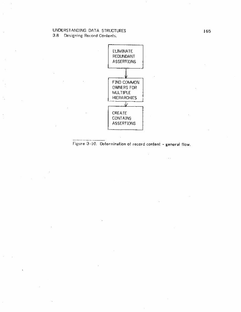
UNDERSTANDING DATA STRUCTURES 1653.8 Desip_ning Record Contents.
ELIMINATEREDUNDANTASSERTIONS
_FIND COMMONOWNERSFORMULTIPLEHIERARCHIES
_ _CREATECONTAINSASSERTIONS
Figure 3-10. Determination of record content -general flow.

UNDERSTANDING DATA STRUCTURES 1663.8 Designing Record Contents.
RU_L!_.NN_AMjE TYPE PRE AND POSTCONDITIONS
ELIMINATE, $5 INORABOVE(I,A,C)AINORABOVE(I,B,D)AREDUNDANIT [[-,=(A,B)AUPLINK(A,B)IvASSERTIONS [=(A,B)A_=(C,D)]]
--,' -4NORABOVE(I,A,C)
FIND $5 INORABOVE(I,A,C)AINORABOVE(I,B,D)ACOMMON -,=(A,B)ACOMTOP(A,B,E)OWNERS
-,INORABOVE(I,A,C)AINORABOVE(1,B,D)AINORABOVE(I,E,A)
CREATE $5 INORABOVE(I,A,B)CONIAINS
ASSERTIONS -* -,]NORABOVE(I,A,B)ACONTAINS(A,I)
LINK UP RECURSIVE HIERARCHYGROUP(B,A,S)v$3 [HIERARCHYGROUP(C,A,S)AUPLINK(C,B)]
-_ UPLINK(A,B)
COMMON $3 UPLINK(A,C)AUPLINK(B,C)TOP I
I _ COMTOP(A,B,C)
COMMON $5 =(C/GENSYM))TOP 2 (IF TOP i FALLS)
-+ COMTOP(A,B,C)AHIERARCFIYGROUP(C,A,(GENSYM))AH]ERARCHYGROUP(C,B,(GENSYM))
Figure 3-I1. Rules for establishin B record contents.
UNDERSTANDING DATA STRUCTURES 167
3.8 Designinr@ Record Contents.
3.8.1 Eliminate redundant assertions.
The system first eliminates redundant INORABOVE assertions. INORABOVE(I,A,.-)
is redundant if item ! is also specified to be in or above another record B, and B
is physically above A (using transitivity). This makes ]NORABOVE(I,A,C)
redundant because INORABOVE(I,B,-) implies that ] is above A.
3.8.2 Find_ common owners.
If, following the elimination of redundancies, more than one INORABOVE assertion
remains for item l, then some record, say X, must be found which connects the
separate substructures in which I is referenced. COMTOP finds such a record,
or generates one if it does not exist. In either case all INORABOVE assertions
referencing [ will be replaced by [NORABOVE(I,X,-).
When record generation occurs, there will be a COMTOP assertion in the final
data base slruclure to indicate to the DBA the reason for the existence of the
generated record. A COMTOP assertion, as does a RING assertion, probably
signals an erroneous use or omission in the set of queries used by the structure
designer.
3.8.3 Create CONTAINS assertions.
After all appropriate Common Top processing has been done there will be
exactly one INORABOVE (],A,-) for each item I, indicating that the item should be
contained in Record A. All remaining assertions are therefore directly

UNDERSTAN[]ING DATA STRUCTURES 1683.8 Designing Record Contents.
transformed by the third rule to CONTAINS(A,]).

UNDERSTANDING DATA STRUCTURES 169
3.9 Ex amEle._
Figures 3-12 through 3-19 give a detailed example of the design process. The
user's queries are given in Figures 3-12 to 3-17. This is not a complete set of
queries for an anticipated implementation so the resulting data base structure
will probably not be complete. In each query, the system prompts are
underlined to distinguish them from user replies. For expository purposes,
these queries are somewhat contrived.
Figure 3-t8 contains the asse/tions generate d in the first phase. Figure 3-i8
also indicates which additional assertions resulted from each query when the
queries were processed in numerical order. Had the queries been processed in
a different order, the resulting set of assertions would have been the same but
the subset of a_sertions added by a particular query might have been different.
Figure 3-19 contains the data base structure design as output by the system.
The COMTOP assertion for system-created record SYMI2 (containing DOCNAME)
will lead tile DI3A to discover an error in tile first query where DOCNAME is
indicated wiftlin the context of the PATIENT record and not in the context of a
possible confluent hierarchy. (PATIENT is the top level record of the first
query.)
A representation of the resulting data base structure using data structure
diagrams is given in Figure 3-20. The six queries used were initially created to
UNDERSTANDING DATA STRUCTURES 1703.9 Example.
debug the aulomatic programmer of Chapter 2 using the data base of Figure
2-28. It is therefore interesting to note the close similarity between the human
designed data base of Figure 2-28 and the machine design of Figure 3-20.
Primary differences are the lack of inversion for the PATIENT record on RACE
and SEX (although lhe syslem suggests SEX as a CALCPORT), the non-existence
of a confluent hierarchy for DOCTOR and HOSPITAL record% and the omission of
a HOSPITAL .- PATIENT hierarchy.
Since the queries consider a HOSP[TAL-DOCTOR but not a DOCTOR-HOSPITAL
hierarchy, the confluency is not present in the designed data base structure.
Similarly, none of the queries reference a HOSPITAL-PATIENT hierarchy, so this
structure is also not included.
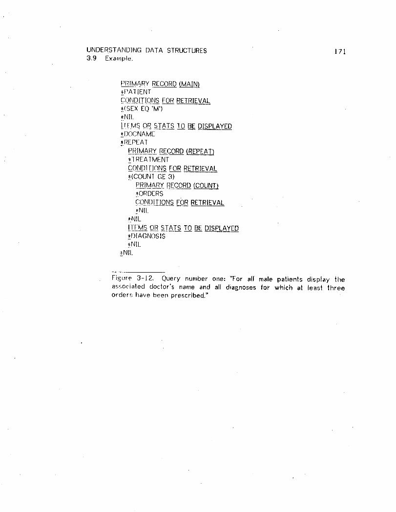
UNDERSTANDING DATA STRUCTURES !713.9 Example.
PRIMARY RECORD_:PAIlENTCONDITIONSFOR RETRIEVAL,(SEX EQ 'M')_:NII.
I:!:EMSC)RSTATS TO BE DISPLAYED*DC)CNAME,REPEAT
PRIMARY RECORD(REPEAT)_l REAIMENTCONDITIONSFORRETRIEVAL.*_(COUNTGE 3)
PRIMARY RECORD(COUNT)_ORDERSC#_ND[_TJ_QNSF_ORRETRIEVAL,NIL
,NIL]F[:MS OR STATS TO BE DISPLAYEB*DIAGNOSIS,NIL_
_.NIL.
Figure 3-12, Query number one: "For all male patients display theassocialed doctor's name and all diagnoses for which at least threeorders have been prescribed."

UNDERSTANDING DATA STRUCTURES 1723.9 Example.
PRIMARY RECORDMA_*DOCTOR_!N[),ULIO_NS_FOR RETRIEVAL,_((:(:)LINTGT 5)
PRIMARY RECORD(COUNT)*PATIENTCONDITIONSFORRETRIEVAL
*.(SEX EQ 'My)*NIL
*NILII[::MS OR STATS TO BE DISPLAYED
_DOCNAME*Rf!P[!AT
[_[_3MARY_R_ECORD(REPEAT)*TREATMENTCOND[] IONS FORRETRIEVAL._!(SEXEQ _M')*Nil__A.
.[]-.[:_M_OR STATS TO BE DISPLAYED_:DIAGNOSIS*PAl NO
*_PATNAME*NIL
*Nil_
Figure 3-]3. Query number two: "For all doctors having more lhan fivepatients, display the doctor's name and the diagnosis, patient's name andnumber for every male patient being treated by that doctor."

UNDERSTANDING DATA STRUCTURES 173
3.9 Example.
PRIMARY RECORD(MAIN),PAIIENICONDITIC)NSFOR RETRIEVAL• (COt]Nr EQ 6)
PRIMARY RECORD{COUNT),DOCTORCONDITIONSFORRETRIEVAL*.NIL
• (PA-rNO LT 6000)*hill
]_[LM__O__RRSTAI_____ST_Q_OBE:DISPLAYED*_PATNAME,PAINO,REPEAT
[_[?]MAR__YYRECORD(REPEAT),BI[_LENTRYCONDITIONSFORRETRIEVAL•,(AMOUNT GT I00),Nil_l][ MS ORSTATS TO BE DISPLAYED,AMOI.JNT,C(-)DE,NIL
*HOSPNAME,NIL
Figure 3-J4. Query number three: "For all palienls with exactly 6doctors and who have a patient number less than 6000, display thepatient's name, number, hospilal and the amount and code for all billsover $ 100."

UNDERSTANDING DATA STRUCTURES 1743.9 Example.
PRIMARY RECORDMAEM__zHOSPITALCONDITIONSFORRETRIEVAL,ANY
PRIMARY RECORD(ANY)pDOCTORCONDITIONSFOR RETRIEVAL,_.(DOCNAMEEQ 'SMITH'),ANY
PRIMARY RECORDA_,TREATMENTCONDITIONSFORRETRIEVAL*_(DIAGNOSISEQ'TUBERCULOSIS_),NIL
,_NIL*NIL.HEMS_OR STATS_TO BE DISPLAYED_.HOSPNO,NIL
Figure 3-]5. Query number four: "Display the hospital number for allhospitals tha| have a doctor named Smith who has diagnosedtuberculosis."
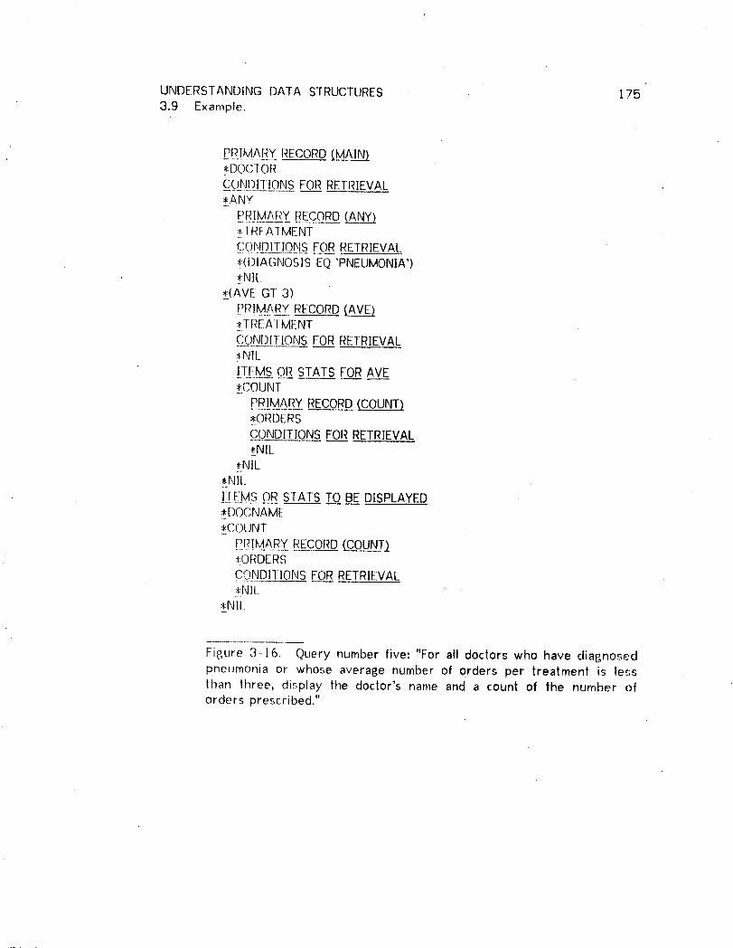
UNDERSTANDING DATA STRUCTURES 1753.9 Example.
[2[?.[MAR_YRECORDMA__*.DOCTORCONI)ll]ONS FORRETRIEVAL,ANY
PRIMARY RECORDA_,I REAl MENT
g_C)h_2_ IQb!_ FORRETRIEVAL_!(DIAGNOSISEQ 'PNEUMONIA'),NIL
,(AVE GT 3)
:__TREAIMENTCONDITIONS FOR RETRIEVAL,NIL_.
ITEMS OR STATs FOR AVE
_*.COUNT
PRIMARY RECORD (COUNT)*ORDERSCONDITIONS FOR RETRIEVAL.*-NIL
*NIL,Nil.
I_:_[!:M_S_OR STATS TO BE DISPLAYED_*DOCNAME,COUNT
P._[_!MA_RY_R_E_COR__DD(COUNT)_!ORDERS.C..O_ND]TIONSFORRETRIEVAL,NIL
,Nil..
Figure 3-16. Query number five: "For all doctors who have diagnosedpneurnonia or whose average number of orders per treatment is lesslhan three, display the doctor's name and a count of the number oforders prescribed."

UNDERSTANDING DATA STRUCTURES 1763.9 Example.
PRIMARY RECORD*PAIIENT
CONDITIONSFOR RETRIEVAL*(PA]NO EQ /0),NE
I__[EIM:S_O_ESTATS T_._OBE:DISPLAYED,MIN
PRIMARY RECORD_ORDERSCONDiTiONSFOR RETRIEVAL.*NIL
!!_M___OR_STATS FO_.RRAV_.EE,ORDNO_!NIL
,NIL
FiglJre 3-/7. Query number six: "For the patient with the number 10,display tile smallest order number prescribed for that patient."

UNDERSTANDING DATA STRUCTURES 1"773.9 Example.
RE_Q ASSERTION6 CALCPORT(PATNO)4 CALCPORT(DIAGNOSIS)4 CALCPORT(DOCNAME)1 CALCPORT(SEX)6 ABOVE(PATIENT ORDERS)5 ABOVE(DOCTORORDERS)4 ABOVE(HOSPITALDOCTOR)3 ABOVE(PATIENT BILLENTRY)3 ABOVE (PATIENT DOCTOR)2 ABOVE (DOCTORTREATMENT)2 ABOVE (DOCTORPATIENT)1 ABOVE (TREATMENTORDERS)I ABOVE (PATIENT TREATMENT)6 INORABOVE(ORDNOORDERSPATIENT)4 INORABOVE(HOSPNOHOSPITAL PORT)4 ]NORABOVE(DOCNAMEDOCTORHOSPITAL)3 INORABOVE(HOSPNAMEPATIENT PORT)3 INORABOVE(CODEBILLENTRYPATIENT)3 INORABOVE(AMOUNTBILLENTRY PATIENT)3 1NORABOVE(PATNAME PATIENT PORT)3 INORABOVE(PATNOPATIENT PORT)2 INORABOVE(PATNAME TREATMENTDOCTOR)2 INORABOVE(PAINO TREATMENTDOCTOR)2 INORABOVE(DIAGNOSISTREATMENTDOCTOR)2 INORABOVE(SEX TREATMENTDOCTOR)2 INORABOVE(DOCNAMEDOCTORPORT)2 ]NORABOVE(SEX PATIENT DOCTOR)l INORABOVE(DIAGNOSISTREATMENT PATIENT)I INORABOVE(DOCNAMEPATIENT PORT)1 INORABOVE(SEX PATIENT PORT)
Figure 3-18. Assertions generated from queries I - 6.
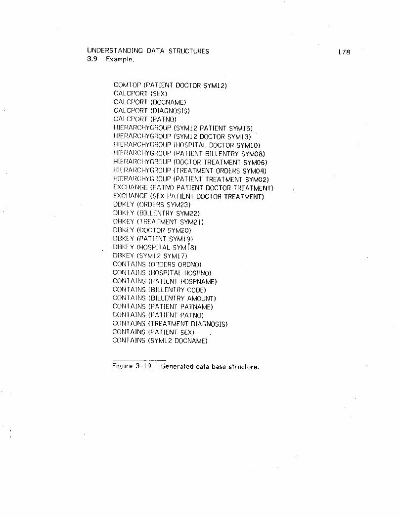
UNDERSTANDING DATA STRUCTURES 178
3.9 Example.
COM]OP (PATIENT DOCTORSYMI 2)CAL.CPORT(SEX)CA[ CPORI (DOCNAME)CA[ CPORT{DIAGNOSIS)CAI_CPORI (PATNO)H]ERARCHYGROUP(SYMt2 PATIENT SYM]5)H}ERARCI-tYGROUP(SYMI2 DOCTORSYM13)_tlEt:_ARCHYGROUP(HOSPITALDOCTORSYMI0)HIERARC.HYGROI.IP(PATIENT BILLENTRYSYM08)t4IERARCHYGROUP{DOCTORTREATMENTSYM06)HIERARCHYGROUP(TREATMENTORDERSSYM04)HIERARCHY(;t_OUP{PATIENT TREATMENTSYM02)EXCI-tANGE(PATNO PATIENT DOCTORTREATMENT)EXCttANGE (SEX PATIENT DOCTORTREATMENT)DBKEY (ORDERSSYM23)DBK[_Y(BILLENIRY SYM22)Df_KEY([REATMENT SYM21)DI:]KI:-Y(DOCIOR SYM20)DBKEY (PATlENT SYMI9)DBKEY (HOSPITAL SYM].'8)DBKEY (SYMI2 SYM[7)CONIAINS {ORDERSORDNO)CONTAINS (t_OSPITALHOSPNO)CON-IAtNS (PATIENT t4OSPNAME)CONIA1NS (B1LLENTRYCODE)CONTAINS (BII.LEN]RY AMOUNT)CONrAINS (PATIENT PATNAME)COI',IIAINS (PA]IENT PATNO)CONIAINS {TREATMENT DIAGNOSIS)C()NIAINS (PATIENT SEX)CONTAINS (SYMI 2 DOCNAME)
Figure 3-.19. Generated data base siructure.

UNDERSTANDING DATA STRUCTURES 1793.9 Example.
SYMI2 HOSPITAL
docname hospno
sY_,_,J s_ ,_i,oI t I "
BILLENI RY I I 1"REATMENT
code, amount I I diasn°sis
SYMO_.
ORDERS
, ordno
Fisure 3-20. Data Structure diasram for Figure 3-i9.
UNDERSTANDING DATA STRUCTURES 180
3.10 Alternative [rnplementation.
An earlier and different version of the automatic data base designer was also
implemented. The difference between the two versions should interest those
who build knowledge based systems.
To build the DMt.P ] had to capture my knowledge of programming in a set of
rules which could be used and understood by tile APG system. The first of the
two data base designers was also built in this way. The result was a system
which at least partially modelled my own behavior when designing data base
structures: evolutionary. That is, tile structure evolves during a period of time
in which ] become more familiar with user requirements. This has the
advantage that at all times my current understanding of user requirements is
captured in the current data structure.
ImplementinF., this strategy in an automatic designer leads to some difficulties.
These diffi(ulties arise because as time structure evolves it is frequently
necessary to make assumptions or to choose from several equally viable
alternatives. This makes the process rather ad hoc, especially later in the
design when further constraints require thal some earlier assumptions and
choices be undone. Programming this strategy therefore requires a
precognizance of all possible occurences of the situations where ad hoc
decisions are necessary.

UNDERSTANDING DATA STRUCTURES 181
3.10 Alternative Implementation.
It became quickly obvious that such pre-planning is very difficult. There were
frequent additions and modifications to the system for handling conditions that
had not been forseen. Furthermore it was impossible to prove any consislency
in system outputs.
The second implementation, which grew out of the frustrations from the first
differs in that the desip_n does not evolve. The second system puts information
extracted from queries into an unstructured pool until a command is given to
generate a de_,ign. One improvement is that all different orderings of inputs
yield identical results. Other improvements are that outputs are easily provable
from inputs, and errors and inconsistencies in the input are more visible in the
resulting data structure.
Although less rigorous than the second implementation, the first method is
probably better for human designers. The second method requires storage of
an unrelated set of facts (a_sertions), something which computers do well but
people don't.

UNDERSTANDING DATA • sTRUCTURES 182
4 EXTENSIONS.
This chapter describes further work that can be done along the lines set out in
the preceding chapters. I will first discuss immediate extensions to the existing
systems for retrieval program generation and data structure design. There are
also two sub-sections thai describe extension of the techniques into other data
base programming areas', data base update and data base restructuring,
4.t. Extensions to the DMLP.
The extensions discussed below are immediate because a Conceptualization of
their implementation in the existing systems is quite clear. ] would estimate an
average implementation time of I week per itemized extension, or approximately
3 man-months for all those itemized below.
4.1.01 Generation of the Data Division.
Tile program generator creates only a Procedure DiVision. There are several
other divisions needed to make a complete COBOL program. The mosl
significant of these is the Data Division. The reason for non-generation of the
Data Division is that the major portion is generated by the Sub-Schema
processor defined by the DBTG. Incorporation of the major portion of the Data
Division can therefore be accomplished by including an appropriate COPY
statemenl. A Data Division so derived must be extended only to include
temporary working storage locations that are used by the Procedure Division.
4

UNDERSTANDING DATA STRUCTURES t83
4.1. Extensions to the Retrieval Program Generator.
The generated Data Division would appear as follows:
DATA DIVISION.FILE SECTION.
FD DUMMY COPY <sub-schema-library-file>.WORKING-STORAGE SECTION.77 X! PIC <> USAGE <>.
77 Xn PIC <> USAGE <>.
The <sub-schema-library-file> must be supplied by the user. The X1 through
Xn are the working stora6e variables used by the Procedure Division. Picture
and Usage clause parameters will be the equivalent of the Picture and Usage
clauses for the source data name if the variable is used to calculate a total,
average, minimum or maximum of the item identified by the source data name.
Otherwise lhe variable will have "PICTURE 9(]0) USAGE COMP".
4.1.02 _qctiv.__Ee port selection.
• In the present system, if a calculated key is used in a disjunction such that it is
used as a port, then it must be so used in everydisjunct. This requirement can
be relaxed by requiring only that every disjunct must contain a port. Note that
this requirement does not state that each such port must refer to the same
calculated key.

UNDERSTANDING DATA STRUCTURES 184
4.1. Extensions to the Retrieval Program Generator.
4.1.03 Recursive processiny_.
A data base that contains a structure of the type given in Figure 4-] can
contain record types that are recursively linked to themselves. For example,
the Bill of Materials paris structure for a manufacturing or assembly opera|ion
can be stored in this type of data base structure.
RECORD A
ISET SET2
¢ ,,, N_'
RECORD B I
Figure 4-1. Recursive network structure.
In its present state, the system is "almost" capable of processing such a
structure to a predetermined number of levels but in a very inelegant wayl the
user must specify each level to be processed, and one or more separate
program paragraphs will result for each such level.
A much more elegant generated program would contain recursively entered
paragraphs, such that each level can be processed by the same program
segment. Thi_ type of program generation would require special recognition of

UNDERSTANDING DATA STRUCTURES 1854.t. Extend;ions to the Retrieval Program Generator.
a recursive slruclure, incorporation of stack logic, and inclusion in HI-IQ oft
special commands for this type of retrieval.
4.1.04 Allow s__e_tname specification by the user.
The system should allow knowledgeable users to specify set names, e.g. define
portions of the access path. This would allow resolution of possible ambiguities
by the user, and user override of the program generator where appropriate.
This improvement would be necessary to erase the "almost" in the second
paragraph of 4.t.03, above.
4.1.05 _Ar[!t!meti_£ a__n_d[_ items.
This would allow the user to specify the calculation of values from data base
items. Temporary items would be implemented to store the results of arithmetic
and also to allow calculations or tests involving several occurances of the same
item.
4.t.06 Distinp_uish ERRORSTATUS values.
At present, the system examines ERRORSTATUS only for a non-zero condition,
and then assumes that an expected error condition, such as end of set, has
occurred. []y examining the actual value of ERRORSTATUS, the system can
determine if tile condition is as expected or truly represents an error that
should be reported to the user.

UNDERSTANDING DATA STRUCTURES ]864.1. Extensions to the Retrieval Program Generator.
A preferred implementation would require modifications to the DBTG
specification. ]his preferred implementation would provide for an error filter
resident in the data management routines but controlled by the run unit. This
filter could be set to ignore certain conditions, trap on other conditions, and
report a third set of conditions directly to the user.
As an alternative, such an error filter could aiso be directly incorporated as a
standard section of the 8;enerated Procedure Division.
4.1.07 Efficient use of sorted sets.
DBTG provides for sets whose members are ordered on key values. Sequential
searches that are dependent on ttle key value can be terminated when the key
value of lhe current set member is higher than the key value range for the
search condition.
4.t.08 OrderinA o_fconjuncls and disjuncts.
When a compound conjunction is to be tested, the resulting program will be
more efficient if the conjuncts are ordered so that the cheaper and most
restrictive tests are performed first. Determining the best order is a complex
task since the cheapest test may not be the most restrictive.
Disjuncts shooId be ordered with the cheapest and least restrictive test first.

UNDERSTANDING DATA STRUCTURES 1874.1. ExtentJons tothe Retrieval Program Generator.
Possible measures of test cost are the number of lines of generated code, the
number of performs in the generated code, or the number of data access
statements required for the test.
A determination of expected restrictiveness is more complicated although a
certain simple-minded ordering is possible with equality tests rated as most
restrictive, then weak inequalities, and finally strong inequalities. Further
delerminalion of restrictiveness would be more costly and would require
knowledge of data base content. See the next paragraph.
4./.09 Order in&of test arguments.
Tests are always of the form (A REL B), where "A" and "B" have some
determinable value and REL is an equality or one of the inequality relations. If
only one of A or B requires a statis|ic calculation in order to determine its value,
then it is more efficient to determine the value of the other (non statistical)
argumenl first. This is so because, if the value of the non statistical argument
is known, then il is frequently possible to determine the truth value of tile test
without calculating the exact value of the statistic. See section 2.9.
4.1.10 S"!_ro_np_ersystem tesls.
It is possible to strengthen the test used to terminate the calculation of a
statistic (as discussed above) if the type of REL is taken into consideration. See
section 2.9.

UNDERSTANDING DATA STRUCTURES 188
4.1. Extensions to the Retrieval Program Generator.
4.1.11 Use of data characteristics.
This extension is discussed in detail in section 2.9.
4.1.12 Removal of eqqivalent parap_raphs.
As can be seen in Figure 2-31, where paragraphs 105 and 301 are equivalent,
the syslem may generate duplicate paragraphs.
A "quicky" solution would be to search the resulting program for duplicate
paragraphs. [t would be more elegant to catalo 6 each paragraph as a
subroutine as it is generated. Each such catalogued paragraph then becomes a
theorem that can be used for subsequent program generation.
4.1.13 Combination o_[fstatistical calculations.
If several different statistics are to be calculated over |he same domain then the
generated program will contain separate program segments for the calculation of
each type of statistic. That is, all totals over the same domain will be calculated
within the scope of a single PERFORM. However, if a count is also to be
calculated over the same domain it will be counted in a separate section of the
program thai is invoked by a different perform.
This method of program generation leads to larger programs than necessary and
can have an extremely negative effect on run-time efficiency.
UNDERSTANDING DATA STRUCTURES 189
4.l. Extensions to the Retrieval Program Generator.
A solution would require the detection of similar calculation domains by the
Request ttandler. This can be done by checking for similar LINKS asserlions
prior to making a new LINKS assertion. It would be necessary to change the
LINKS assertions so that multiple actions can be specified.
4.t.14 It_terfaces to externally coded prop_ram segments.
As it stands now the system generates acomplete Procedure Division. The data
retrieved by the generated program is simply displayed. In an actual operating
environment, it may sometimes be desirable to process.the retrieved data with a
report writer, perform complex analyses, or output it to other devices. This
suggests using the program generator to write sections of procedure that
combined with other sections form a complete Procedure Division.
The machine generated sections would serve as data Iocators. Ralher than
displaying the data, such sections would simply assure its presence in Working
Storage.

UNDERSTANDING DATA STRUCTURES 190
4.2 Exlensiqn_s Io th_Ae_D_a!aStructure Desip_ner.
4.2.t Generate complele
The designer iF_nores many data characteristics that might result jn the desiF_n of
a more efficient data base. A data base is more efficient if it requires less
storage space, or if the total time required to process information therein is
reduced.
There are also design issues, unrelated to the structural design, that must be
considered for a con_Aplete data base design. Extending the designer to consider
these issues and to make use of data characteristics is a proper next step.
4.2.2 Practicality_ of p aradiP_m.
The "practicality" of accumulating a complete set of queries prior to attempting
the design is open to question and should be investigated.
4.2.3 Further cost study=
Empirical study of the costs of human performance on equivalent design tasks is
needed to determine if automatic data base design is less costly.
4.2.4 Recursive slructures.
There is a particular substructure in network data bases for the storage of
recursivety linked records (Figure 4-l). If tile programmer is to be extended as
in section 4.1.03, then the designer should be extended in an equivalent fashion.

UNDERSTANDING DATA STRUCTURES 1914.2. Extensions to the Data Structure Designer.
4.2,5 EyE_,lore alternative designs,
The dala structure design arrived at by the system may be one of many
possible designs for the set of queries. An extension to allow the generation of
alternative designs (or at least indicate to the DBA which portions of the design
are fixed and which are not)is suggested.

UNDERSTANDING DATA STRUCTURES 192
4.3 AL__2to__.mmatipj__of Data Base Update.
The traditional view of update is that it consists of three types of tasks; record
addition, record deletion, and record modification. The latter two tasks are
essentially similar to retrieval because a retrieval of the record in question must
precede lhe execution of lhe actual update. Not much modification of the
programmer would be needed to provide it with an update capability for
deletion and modification.
Since records in a network data base may be linked to many other records,
addition of records requires that all of the links be properly established. A
record.addition must therefore be preceded by several record retrievals, each
retrieval locating one of the records 1o which the new record is to be linked.
•Code generation for these retrievals has already been demonstrated.
Determination of the set of records to be retrieved and the criteria for their
retrieval is still an unsolved problem.
This problem does not appear to be too difficult, however. The set of records
is determined by finding all H]ERARCHYGROUPs that contain the record to be
added. The criteria for the retrieval of this set of records cannot be
determined without some knowledge of the LOCATION MODE parameters defined
in the Schema. The system would therefore have to be extended so that it can
"understand" these parameters.

UNDERSTANDING DATA STRUCTURES 193
4.3 Automation of Data Base Updale.
An update program generator should also be influenced in its programming by
the batch vs on-line dichotomy. The batch processing type of program cannot
communicate with the user in realtime, a restriction thai does not apply to the
on-line program. [he system already has a limited capability for interactive
information relrieval, and it should be possible to handle on-line transaclion
processing in the same way.
Batch updating requires that the structure of both the ,transaction and the data
base be defined. Allhough [ have not investigated this in detail, I am confident
that the methods used for retrieval program generation are applicable without
major extension.

UNDERSTANDING DATA STRUCTURES 194
4.4 Data Base Restructurinp..
Restructuring becomes necessary when errors or oversights are detected in the
current data structure or when changes in demand require a change in data
structure. Such a data structure change may make certain programs obsolete
and may also require that the data itself be manipulated and restructured.
Restructuring can therefore be very cosily, especially for large data bases.
The DMLP can have a beneficial impact on the costs of reslructuring by reducing
the reprogramming effort, thereby reducing programming costs and elapsed
tim& In addition to this immediate benefit, the technology and theory
developed in lhe preceding chapters suggest a method that can totally eliminate,,
the disruption usually associated with restructuring. The disruption is6
eliminated by "dissolving" the restructuring process in the normal usage of the
data base.
An explanation of this method requires the introduction of a new concepll dala
structure generations. Whenever a structure is modified, the QId structure
description is not discarded; instead the new structure is recognized as a new
structure generation and is assigned an incremental generation number. The
current structure generation number is used to mark records when they are
stored so thai the appropriate structure descriplion can be used when these
records are later retrieved. Under this _,cheme multiple generations of
structure would be allowed to exist simultaneously in the data base.

UNDERSTANDING DATA STRUCTURES 1954.4 Data Base Restructuring.
Prol_rams are also marked with the identifying number of the generation in
effect when the programs were written.
The system is therefore capable of detecting differences between the assumed
structure in a program and the actual structure in the data base by comparinF,
structure F_eneration markers. As a result, whenever a program attempts to
navigate through ._,omestructure that belongs to a different generation than the
program, the system provides a subprogram that makes the data structure
differences transparent to the program. The previous chapters have shown
how these subprograms can be generated whenever the generation differences
are limited to attribute migration or hierarchical inversion.
Generation data structures may also differ in the paths that exist between
record types. Again, this is adifference easily resolved.
Differences that are not so easily resolvable are structures that differ in
possible information content. In such cases the system must ask for human
intervention or operate from a set of well-known assumptions. There may be
other structural changes that cannot be handled automatically.
Implementation of this type of system provides a choice regarding the actual
reformatting of the data. In highly volatile data bases actual reformatting can
be indefinitely postponed because of the rapid decay of out-of-date structures.

UNDERSTANDING DATA STRUCTURES 196
4.4 Data Base Restructuring.
A second alternative is to cause automatic reformatting of out-of-date
structures as they are encountered in the course of hOt'real processing.
The latter method assumes that "local" restructuring is feasible. I would expect
situations to occur in which this assumption is not valid. Since all data is linked
together, "chain reactions" might occur: a single change causes access to
another record that must also be modified, causing access to another
out-of-date structure, etc.
UNDERSTANDING DATA STRUCTURES 197
5 COST EFFECTIVENESS OF AUTOMATIC PROGRAMMING.
The true costs of this application of Artificial Intelligence cannot be measured
until the application process is completed, that is, until the program generator is
used wilh an actual data base to solve actual retrieval problems. Some
measurement of program generation and data structure design has been done
however. Considering the fact that the implementation utilizes interpreted LISP
and Micro-;Planner, both of which are notoriously expensive [Sussman and
McDermott 1972], these costs appear to be quite promising.
5.l Measures of Automatic Program Gffneration.
Table 5-1 gives values of various measures of the program generation process.
The queries and their corresponding programs are named P1 through P6. The
first column of the table contains a measure of the size of the problem
statement. The values in this column indicate the number of input lines
containing entries other than "NIL" (a terminator) entered for the query. The
next two columns are a measure of the complexity of the programming task_
indicated for each program is the number of rules the system attempted to use
and the number of such attempts that were successful.

UNDERSTANDING DATA STRUCTURES 1985 Cost Effectiveness of Automatic Programming.
PROB RULES COBOL RUN K-CORE $LINES USE SUC LINES PARAS TIME SEC
PI I0 58 49 ....P2 13 84 77 32 8 4:09.1 5988 64.70P3 14 118 102 67 11 6:22.5 9229 97.87P4 16 128 107 61 11 5:26.2 7862 82.56P5 20 99 88 30 4 3:14.4 4681 49,19P6 12 79 62 29 4 2:55.9 4230 44.34TOTAL b66 485 219 38 22:08.1 31990 338.66
Table ,5--1. Costs of automatic program generation.
Columns five and six measure the size of the resulting COBOL prograrns in terms
of both lines of code and number of paragraphs produced. The lines produced
count is conservative: lines which label paragraphs or sections are not included
in the count. Furthermore, lines of excessive length which are continued on a
subsequent line are only counted as a single line.
One observalion here is that the size of the problem statement is not a good
measure of the size of the resulting program nor of the generation cost. A
large• problem statement may result in a relatively small program (as is the case
with PS) if the relations in the problem statement correlate highly with _'ecords
in the data base.
The final three columns of Table 5-1 indicate some direct measures.of cost of
the DMLP, l_he first of these indicates run time in minutes and seconds, lhe
second colurnn indicates the number of kilo-core-seconds used; and the las|

UNDERSTANDING DATA STRUCTURES 199
5 Cost Effectiveness of Automatic Programming.
column gives a total dollar charge for the usage as calculated on
Carnegie-Mellon's DEC-IO computer. The primary component of the charge
incurred by the program generator is the kilo-core-seconds used because it
uses a lot of storage. The Carnegie-Mellon charp=e is approximately 8,O/ per
kilo-core-second. This compares to an in-house charge of $.0007 per
kilo-core-second at First National City Bank and an outside' vendor charge of
$.O3 per kilo-core-second [Summers 1974], all for DEC-IO's.
The cost measure has only been obtained for the generation of the last five
programs in the table. These five programs contain 219 lines o_ COBOL source
code (including DML statements) and cost a total of 8338.66 in computer time to
p=enerate. This gives a mean cost of .81.55 per line of code with a range of
8t.35 to $2.02 per line generated.
It is tempting to compare the cost of 81.55 per line of code with equivalent
values measured for human programmers. Before I do so, some cautionary
statements are in order. The figure of $1.55 per line is a variable cost and
does not take into consideration the costs of development of the DMLP.o
Secondly, the cost to derive the problem statement, a human cost, is not
included. [hirdly, it is certainly possible that the program obtained may turn
out to be unsatisfactory because of errors or omissions in the problem
statement. Such .a condition will require a further i|eration of program
generation, and each such iteration will add an additional 8].55 per line to the

UNDERSTAND]NG DATA STRUCTURES 200
5 Cost Effectiveness of Automatic Programming.
cost of the final program. Obviously, an extension to the system which would
allow it to modify previously generated programs without a complete
regeneration would be of great value.
5.2 Cost Factors in Pro_ramminP_.
The cost of the DMLP will be compared with costs calculated from four differ.ent
sources. The predicted number of man months and computer usage for IO00
lines of COBOL code are given for each source in Table 5-2. A very detailed
study of cost factors was carried out at the System Development Corporation
and has been reported in [Nelson /966; LaBolle 1966]. This study, also
discussed in [Sharpe /969], is based on observations of 12 COBOL programming
projects. ] have included bolh the minimum and the mean cost factors from the
SDC study.
NELSON BRANDON DELANEY BAKER NELSON(mean) MILLS (rain)
MAN MO. 4.83 7.0 6 1.72 .27COMP HRS. ]&08 20.5 25 7.22 l.t8
Table 5--2. COBOL cost factors for 1000 source lines.
The Brandon study [Brandon ]963] gives normative (standard) values for
resource expenditures for programming in COBOL on the IBM 7080. Brandon

UNDERSTANDING DATA STRUCTURES 20]
5 Cost Effectiveness of Automatic Programming.
provides an algorithm for calculating these values which is dependent on the
complexity as well as the size of the program. Brandon's algorilhm has a fixed
cost component. As a result, the cost per line will be somewhat lower for
lengthier programs, all other things being equal. The figures given in Table b-2
were linearly exlrapolated from values obtained from the algorithm for a 280
line COBOL program of average complexity.
Delaney_s algorithm [Delaney 1966] is simply based on a productivity rate of ]O
lines of code per man day_ plus a 25Z additional cost for program checkout.
Computer time is caculaled at the rate of 1 hour per man week. Delaney does
not indicate how his figures were obtained. The productivity rate quoted by
Delaney is applicable to programming in machine code. The SDC study found
that programmers generate COBOL code at a slower rate than machine code, so
Delaney's figures may be somewhat optimistic for COBOL programming.
The fourth study [Baker and Mills J973] reports the results obtained from a
single programming project at IBM. The computer hours used in this project
were not indicaled, so the figure given in the table has been estimated using the
one-hour-per-man-week rule of thumb. Baker and Mills claim that the
improvement in productivity is due to special management (Chief Programmer
Teams) and programming (structured) techniques. Since the earlier SDC study
showed a very large performance variance, we cannot attach much significance
to the single observalion provided by Baker and Mills.

UNDERSTANDING DATA STRUCTURES 202
5 Cost Effecliveness of Automatic Programming.
All four of lhese sources considered only the programmer's task in calculating
the cost factors. Other costs, such as problem definition cost and design
iteration costs, were not included. Although the Brandon and Delaney
algorithms have a documentation cost component, the values in Table 5-2 do not
include this cost since the DMLP does not generate documentation.
Table 5-2 is fairly consistent with the DMLP as regards the basis for the
calculations. There are, however, some costs that will be incurred with the
DMLP that are not accounted for in Table 5-2. These costs consist of an
investment cost associated with the DMLP, and the cost to phrase the
information retrieval problem in terms of 141-10. These costs, especially the
latter, are not, negligible, but empirical study is needed to determine actual
values.
.5.3 Comparison of Dollar Costs.
By assignin B some dollar costs to the factors in Table 5-2 it becomes possible to
directly compare the various cost predictions (experiences) with the costs
observed for the DMLP. Such a comparison is given in Table 5-3. The minimum
cost line is bar_ed on a man-month cost of SJO00. The reasonable cost line is
based on $3000 per man-month (derived from an annual salary of 8/8,000 plus
lO0_ for burden and overhead).

UNDERSTANDING DATA STRUCTURES 203
5 Cost Effectiveness of Automatic Programming.
DMLP NELSON BRAND.ONDELANEY BAKER NELSON
(mean) MILLS (rain)
M1N COSTS 108 6,638 9,050 8,500 2,422 1,450REAS COSTS ],550 23,530 3],250 30,500 8,770 6,710
Table 5-3. $ Cost for 1000 lines of COBOL in 1974.
Both lines in Table 5-3.:!also take into consideration the machine cost factor. It
is more difficult to determine appropriate charges for Computer usage, because
the computer hour usage figures in Table 5-2 were obtained several years ago.
On the one hand, computer hours to implement 1000 lines of COBOL might be
less today because of the improved efficiency of computer hardware.
Conversely, debugging time might have increased because of the increased
complexity of the programming environment. Furthermore, because of
mUlti-programming, computer costs are no Iongera simple function of CPU time.
As a minimum value, ] will use a charge of $100 per 1963-1966 equivalent
computer hour. This assumes an efficiency improvement factor of 1/5. As a
reasonable value, ] will use a charge of $500 per computer hour. This assumes
that the factors discussed above in combination with inflation have cancelled
; each other out. Table 5-3 cornpares the minimum and reasonable dollar costs
based on the cost factors of Table 5-2 with the costs experienced with the
DMLP.

UNDERSTANDING DATA STRUCTURES 204
5 Cost Effectiveness of Automatic Programming.
The reasonable cost for the DMLP is based on lime charge of $.Ot per k-core
second actually experienced (the cost also includes minor charges for connect
time, etc.), l he minimum cost figure is based on the charge of 8.0007 per
k-core second used for the in-house DEC-tO at First National City Bank.
The DMLP has a dollar cost saving of 927 to 98% in the minimum cost frame. In
the reasonable cost frame, the DMLP reduces cost by 77'_ to 95%.
This reduction in cost leaves a lot of room for absorption of the costs associated
with the DMLP. Note that the costs for the DMLP as actually experienced ate
equivalent to the minimum charges applied to the most efficient project
observed by Nelson; i.e. a "super" programmer working for 8]2,000 a year,
incurring no burden or overhead.
5.4 Exe(ution Costs.
The costs discussed so far are only program generation costs and ignore
execution costs. The execution of computer generated code may be more or
less efficient than the execution of programs written by people. We would like
to think that there is some person who can write a better program than a
machine for any problem. But, the DMLP need only be better than the average
programmer for a net advantage to result from using it.

UNDERSTANDING DATA STRUCTURES 205
5 Cost Effectiveness of Automatic Programming.
5.5 Cost of Data Structure D__eL
It is difficult to judge the cost savings from automatic structure design since
first, the automatic designer only partially replaces the human designer.
Second, this task is quite new and cost experience is not yet available. The
cost of automatic design seems quite low, however. The costs given in table
5-4 were obtained from the DEC-]O computer at Carnegie-Mellon University and
are based on the same charging algorithm as described above.
The design process occurs in two steps. Simple fact accumulation from .the set
of queries is done first. Then the actual design is done from the accumulated
facts. The fact extraction process consists of reading the query and extracting
from it the implicit relationships it contains. Table 5-4 shows that 41 facts
were extracted from a set of six queries containing 55 statements at a cost of
$15.93. -file costs given here were obtained from the exampie given in Chapter
Three.
The second stage of the design process determines a network structure that will
accomodate all of the necessary relations as captured in the facts base. This
process is more complex than fact accumulation and requires almost twice as
much time and a cost of 828.71.
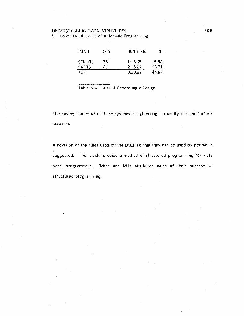
UNDERSTANDING DATA STRUCTURES 206
5 Cost Effectiveness of Automatic Programming.
INPUT QTY RUN TIME $
STMNTS 55 1:15.65 15.93FACTS 41 2:15.27 28,7!TOT 3:30.92 44.64
Table .5-4. Cost of Generating a Design.
The savings potential of these systems is high enough to justify this and further
research.
A revision of lhe rules used by the DMLP so that they can be used by people is
suggested. -this would provide a method of structured programming for data
base pros;rammers. Baker and Mills attributed much of their success to
structured programming.

UNDERSTANDING DATA STRUC[URES 207
6 ON THE APPLICATION OF ARTIFICIAL INTELLIGENCE.
Most successful Arlificial Intelligence (At) programs excercise their problem
solving abilily in unrealistic environments or apply it to a game playing task.
Many of these applications are also not objective Since the problern environment
has been selected and constrained by the Alresearcher. Actual replacement of
human problem solyers with the machine is usually of no value to anyone except
the AI cor_rnunity. Critics of A] can frequently stand unrefuted because much of
what they claim is true: practical and objective applications of At are few and
far between.
To find in lhis crilicism an indictment of AI is unrealistic and unfair. As many of
the proponents of At have claimed in defense, it is necessary for At to cut its
teeth on toy problems, games, and in otherwise limited environments before it
can proceed to fill its highly touted promises. Perhaps the only fair criticism is
that this teeth cutting is taking longer than envisioned by early workers in the
field.
It is my feeling that AI is entering an age where application becomes feasible.
By my statements here I do not mean to imply that there have not been
valuable spin-offs from AI that have contributed to advances in fields such as
computer science, linguistics, and psychology. However, there have not been
many direct applications of complete AI technologies (with perhaps the
exception of the pattern recognition field) to problem areas existing outside the

UNDERSTANDING DA]A STRUCIURES 208
6 On the Application of Artificial Intelligence.
domain of At, and especially outside the academic domain.
My own experience is perhaps a good demonstration of the coming of age of AI.
The background I bring to this research is not primarily .in AI, but lies more in
the area of commercial data processing, data base management, and information
retrieval. My experience in these areas predates by several years my
introductory exposure to AI. ] think this distinction is important because the
problems which will be described shortly, existed for me long before I
discovered the technology to solve them. As such, my circumstances provided a
degree of objectivity not available to the AI researcher Who is looking for
problems to adapt to his technology.
6.1 Data _M_l:__£ement Application.
This thesis describes a system which generates information retrieval programs
and data structure declarations. These two problem solving tasks have been
around for a long time, but growing commercial usage of network data bases has
suddenly increased lheir complexity. (When ] refer to a network data base ] do
not neces.'-,arily mean a data base on a computer network, but one in which a
data item may be linked to many other data items in rings, hierarchies or other
structures.) There has been an attempt within the United States and Canada to
develop a standard for network data"bases through CODASYL which spawned
the inter-academia-industry Data Base Task Group (DBTG). This group has
produced a specification for a general purpose network data base system

, UNDERSTANDING DATA STRUCTURES 209
6 On the Application of Artificial Intelligence.
[CODASYL 1971a]. Although not yet accepted as standard, it is believed by
many thai the DBTG specification will be so adopted, perhaps by default since
many computer manufacturers and software firms are now selling
implementations of the DBTG specification.
Both applications described herein function in the data base environment as
specified by the D[31G. Data structures designed by the system conform to
DBTG specifications, and the generated retrieval programs are COBOL Procedure
Divisions containing Data Manipulation Language (DML) as defined by the DBTG.
This aclherence to external specifications is another important characteristic that
distinguishes this application from other less practical and less objective
applications.
6.1.1 Pr_L_m_ in network data bases.
Introduction of the network type of data base brings with it a new level of
complexity for the business programmer. As Early [Early 1972] points out,
instead of the usual logical-physical dichotomy which a programmer traditionally
deals with, there is a Io_ical(a)-Iogical(b)-physical trichotomy facing lhe network
data base programmer. The logical(a)level corresponds to data relationships as
perceived by the data user. The logical(b)level concerns the actual links
between the data in the data base.

UNDERSTANDING DATA STRUCTURES 210
6 On the Application of Artificial Intelligence.
Bachman recognizes this problem in the [973 ACM Turing Award Lecture
[Bachman 1973] where he likens the programmer's problem (in the network data
base environment) to that of a navigator. The programmer is given the user's
desired data and relationsl his task is |o find the proper access path through the
myriad of connective links in the data base.
This problem, the programmer's problem, should be reduced. After all, much of
the problem is caused by an artifact introduced by ihe data network, the data
links. It should be noled here that others in the field, primarily Codd [Codd
1970, /972a, I g72b], have proposed relational models of data 'bases whereby
they hope to avoid the emergence 'of this artifact. It is not clear to me
however, how this can be done without exactly the kind of problem solving
program which is tile subject of this paper.
Finding a path to certain pieces of data while satisfying certain constraints is
not at all dissimilar lo a complicated robot/maze task. This similarity may be a
partial explanation for the direct applicability of A] technology to the problem.
The technology used is not robot technology however. Instead, the solution
was found in the automatic programming area. Specifically, I used a compiler
developed by Buchanan and Luckham [Buchanan and Luckham 1974_ Buchanan
1974] to create tile data base retrieval program generator. The retrieval
program generator, consisting primarily of a set of Micro-Planner theorems

UNDERSTANDING DATA STRUCTURES 21 I
6 On the Application of Artificial Intelligence.
[Hewitt 1971_ Sussman and Winograd 1972],is compiled by the APGsystem from
a set of rules. These rules are staled in a formalism corresponding to Hoare's
logic of programs [Hoare 1969]. Each rule describes a loop, an assignment
statement, a Data Manipulation Language Statement, or other program construct.
A rule describes the effect of a program construct and the conditions under
which it may be used. For example, the rule for the GET statement states that
(a), it is not possible to GET a record unless its location in the data base is
known to the data management system and (b), following the GET, the record is
• located in working storage. Other rules, especially ones dealing with the
assemblage of larger program blocks, do not bear such close resemblance to
sections of a programming manual as does the rule for GET. These other rules
capture my own programming knowledge which I had previously acquired and
developed as a professional programmer. [t was a difficult exercise to express
my knowledge in the APG formalism.
The rules are translated to Micro-Planner theorems. The resultin 6 program
(consisting of Micro-Planner theorems)is an information retrieval proEram
generator. One of its inputs is the above mentioned data base structure
definition, the other input is a retrieval query. The output is a COBOL
Procedure Division.
The program generator is data base independent, and may generate different
prop=rams for identical queries if the structure is different. This is why the data

UNDERSTANDING DATA STRUCTURES 2 12
6 On the Application of Artificial Intelligence.
base struc.t=lre is one of the inputs to the program generation process. The
design of lhis structure is the subject of the next section.
6..t.2 Desi£,_Lli_nA network data s'_ructures.
Another problem attendant to network data base management is data base
structure design. That is, to design appropriate links to exist between data
elements so that data relationships can be propgrly captured and reconstructed.
Since all such relationships must be implicitly contained in the set of all queries,
it should be possible to derive a data base structure from such a set.
The autonlatic data structure designer operates in exactly this fashion. It
generates a data structure design that is satisfactory for a set of queries.
The power of the ctesign program lies in two areaS. First, it has the ability to
recognize hierarchies and inversions thereof. Detection of a hierarchy lhat is
processed "both ways" leads to the inclusion of a confluent hierarchy in the
designed struclure. For example, a confluent hierarchy would be used to store
information regarding doctors and patients since doctors can have several
patients, and conversely, patients can have several doctors.
The designer also determines the location of data items (attributes) in the
hierarchical slructure. For example, hospital name can be a patient attribute
(where he is bein6 treated), a doctor attribute (where he works), and of course

UNDERSTANDING DATA STRUCTURES 213
6 On tile Application of Artificial Intelligence.
a hospital attribute. If hospital-patient and hospital-doctor hierarchies (several
patients and several doctors per hospital) have already been constructed by the
system, then it will assisn the attribute in question to the hospital record. This
permits usar_e of hospital name as a unique attribute of hospital, doctor, and
patient.
In Early's words, the system has found a Iol]ical(b) arrangement which
accomodates all tosical(a) relationships. As a matter of fact, translation from
logical(a) to Iosical(b) also characterizes the system's activities as a pro6rammer.
Further translation to the physical level is accomplished by the data mana6ement
system, e,£,. an implementation of the DBTG specification. As was the case
with the program 6enerator, the system is defined with a set of rules that are
translated by a compiler to a prosram of Micro-Planner theorems. However, in
this case tile resultin6 system is not a code 8enerator, it is a declarative
8enerator.
6.2 Acquisition and Representation of Know ledp_e.
If a system is to apply knowled6e , it must first obtain such knowledse. The
on6oing work in "1earning" systems is partially motivated by the desire to
minimize lhe effort of buildin8 the knowledse base for a system which must
understand a particular domain. Until 6eneralized learnin8 systems become
available which can be adapted in a practical way for use with a particular
application domain, it is necessary to imbed knowled6e of the application either

UNDERSTANDING DATA STRUCTURES 214
6 On the Application of Artificial ]ntelligence.
I
by buitdin 6 a specific learner for that system or by providing the system
directly with the knowledge it needs. The trouble with the former approach is
that building the learner may turn out to be a more complex task than building
the rest of the system.
The latter approach is the one that was taken for the applications discussed
here. The rule formalism provides a very good framework for capturing
network data base programming knowledge. Even so, capturing the knowledge
was not a slraightforward process and involved many trial-and-error iterations.
The occurrence of so much trial-and-error even when using this formalism is
perhaps surprising. The problem arises because much of the existing
knowledge (residing in the application specialist's head) does not have a well
defined structllre. ]I is possible to map the specialist's knowledge to a
structured set of formal rules in several ways, all of which are valid, but some
of which lead to an extremely inefficient program generation process.
However, some of the knowledge does have a well defined structure, for
example the knowledge regarding GET as discussed above. In general, the rules
for single program statements are very similar to usage rules that might be
found in a reference manual. ]t is the rules that control the next higher level of
programmin 8, the construction of program blocks, that are complex and not
easily derived.

UNDERSTANDING DATA STRUCTURES 2.1.5
6 On the Application of Artificial Intelligence.
Since the content of the rules determines the decision tree that controls the
search space, the choice of mappings mentioned above can have a dramatic
impact on the efficiency of the search for a program. If the use of a particular
rule occurs far out in the branches of the tree, and if the rule is a powerful
discriminator, then it would be appropriate to consider an alternative rule
structure that would permit earlier evaluation of the rule in question.
Notice thai lhi._, makes it very important [hat the applications specialist be very
closely integrated with the AI technologist. Close integration will allow the
specialist's knowledge to be captured in a way that is most effective for the A!
methodology being used. This task is complicated if the AI representation
shows litlle correspondence to the "natural" representation.
in the particular application discussed in this paper, the integration was
accomplished by training the application specialist (myself) to become an AI
technologist. I can only imagine the problems that would result, especially
regarding efficiency, if there is less integration and the two functions are
embodied in different individuals.
Table '5-1 illustrates the impact of close integration on the efficiency of the
resulting application. For example, of the 84 rules that were tried for the
generation of program P2, only 7 were unnecessary. For all six programs, out
of 566 rules tried, 485 were successful. In other words, on average only 14<7_
UNDERSTANDING DATA STRUCTURES 216
6 On the Application of Artificial Intelligence.
of the search takes place in fruitless branches of the tree.
At the present sta_e of A] technology, successful applications will require a high
degree of integration of the AI technologist and the applications specialist.
Until psychologists discover how people store knowledge, it will be necessary
for the applications specialist to "come to the machine" and describe his
processes in AI terminology. Conversely, the AI technologist will need to
acquire a great deal of knowledge about the application.

UNDERSTANDING DATA STRUCTURES 217
7 THE RELATIONAL AND NETWORK MODELS OF DATA BASES.
7.1 l_ntroducJjo_.
Several recent papers on relational and network data base models discuss lhese
models in a choice framework. That is, these papers make the assumption lhat
a choice of one model is to be made, and then argue the supremacy of one
model over the other. Codd and Date [Codd and Date 1974; Date and Codd
1974] recently argued for the relational model, others [Jardine 1974] have
argued the other way.
] find it unnecessary to argue this point. Obviously, the relational model
provides a much better applications interface and a better framework for the
discussion of data bases. But ] ask the rhetorical question' How do proponents
of the relational model propose to implemenl general relational data bases
without utilizing some type of network slruclure? Contemplation of this question
reveals my cenlral premise which is best illustrated by analogy - the relational
model is to the network model as COBOL is to assembly language.
Viewing the two models in this fashion leads to the realization that there is a
need for both models and suggests an approach whereby the relational model
can be developed and incorporated by users in an orderly fashion.
7.2 Levels of Data Structure Description.
Codd [Codd ]970] originally introduced the relational model as a means for

UNDERSTANDING DATA STRUCTURES 2187 Tile Relalional and Network Models of Data Bases.
higher level data structure description. However, just as COBOL and other high
level languages must be translated to a machine level sequence of instructions,
so musl relational representations be translated to access path descriptions.
Early [Early 1972] was the first to formalize tile levels of description attendant
to data bases. Early defined three levels of description:
Ca) relational
(b) access path(c) implementation
The two highest levels comprise, in Early's terms, the semantic level of
description.
Although lhe access path and implementation levels are usually Invisible to the
user of a relational level model, the user should demand standardization at all
three levels, and especially at the access path level. If he does not get such
standardization, he will find that his data base is not transportable across
machines or across various implementations of the relational model.
There are many possible choices of models at the access path level, including
sequential file, indexed file and network data bases, The most general of these
is the network model, and the DBTG report represents a standardization of this
model.
.-'. The network model, primarily as embodied in the DBTG report and its
predecessor, IDS [Bachman and Williams 1964], has enjoyed far greater

UNDERSTANDING DATA STRUCTURES 2197 The Relational and Network Models of Data Bases.
acceptance in implementation than has the relational model. This success is not
due to a flaw in the relational model, but is simply caused by the limitations of
technology. Since the relational model captures a higher level of generality, it
requires further advancements in technology for implementation. In terms of
the preceding analogy, assemblers preceded compilers for essentially similar
reasons.
7.3 Translatior ! _,_,_Ap._pro ach.
Because of lhe increased acceptance and use of DBTG systems, and the need for
using a standard access path model, the next logical step in the development of
the relational model is to devise translators for the translation of relational level
descriptions to DBTG access path descriptions. This allows development of the
relational model on the base of existing DBTG implementations.
] call this the translation approach and differentiate it from the total approach.
The total approach is the approach taken wilh implementations of the relational
model to date. That is, each such implementation is self-contained, and access
path level and implementation level descriptions are hidden from the user. Such
implementations of the relational model therefore usually differ not only at the
user (relational) interface, but also in .the storage s.tructure (access paths) of the
data.

UNDERSTANDING DATA STRUCTURES 2207 The Relational and Network Models of Data Bases.
7.4 Advanta&e._. of translation.
The translation approach offers several advanlages over the total approach:
(a) .orotects current users of DBTG
(b) is exlensible with minimized disruption(c) permits user flexibility
(d) permits orderly development of the relational model
Standardization at the access path level, as was ursed above, is facilitated with
the translation approach. These advantages all acrue because the |ranslalion
approach is well defined (or locked-in) at the access path level.
Once a user's relational description has been translated to a DB'TG access path
description (e.B. COBOL - DML prop=ram), this description then exists within a
fixed framework. Subsequent changes in the relational technolosy or standards
will not affect the user's operations. If he chooses |o, the user can re-translate
selected relational descriptions to take advantage of such modifications.
If the necessary relational technolosy has not yet been developed for a certain
application, lhe user can always fall back on the access path model and manually
8enerate lhe necessary access path descripltonsi or he can modify previously
tr.anslated access path descriptions so that his application is properly processed.
The same options are available for the improvement of inefficiencies caused by
the Benerality of the relational model.

UNDERSTANDING DATA STRUCTURES 2217 The Relational and Network Models of Data Bases.
7.5 Two Implemented Translators.
The DMLP and the automatic designer are translators. The H|-IQ language
(which both accepl as input) allows users to specify queries without worrying
about the structure of the data base. HI-|Q is a relational language because it
lets the user specify queries in terms of the relationships he perceives.
Codd might not agree to this classification of HI-IQ because it is not based on
his relational calculus or algebra and because it does not permit the naming of
relations. This means that multiple direct relationships between two entities
cannot be specified because a name is needed to distinguish between them.
Such multiple direct relationships are infrequent in commercial processing. In
any case, exlension of H[-IQ and the two systems to permit the naming of
relations would not be difficult.
I

UNDERSTANDING DATA STRUCTURES 222BIBLIOGRAPHY.
Bachman, C. W. (]965), "Software for Random Access Processing",Dalamatioq, April 1965, pp36-41.
Bachman, C. W. (1969), "Data Structure Diagrams", Data Base 1_.,2,Quarterly newsletter of ACM-S[GBDP.
Bachrnan, C. W. (1973), "The Programmer as Navigator", CACM _ I l,.November 1973, pp653-658.
Bachman, C. W: and S. B. Williams (J964), "A General Purpose
Programming System for Random Access Memories", Proceedings, FallJoint Computer Conference 1964_ pp411-422.
Baker, Ferry F. and Harlan D. Mills (1973), "Chief ProgrammerTeams", _D&lamation_,December 1973, pp58-6i.
Boyce, R. F., D. D. Chamberlin, W. F. King 111 , and M. M.Hammer (1973), "Specifying Queries as Relational Expressions: Square",IBM Re_,earch RJ 1291, October 1973.
Brandon, Dick H., (1963), Manap,ement Slandards for Data Processing,Van Norstrand Co., Princeton, N.J., 1963.
Buchanan, .I. R. (1974), "A Study in Automatic Programming", PhD• Thesis, Stanford University,
Buchanan, J. R. anti D. C. Luckham (1974), "On Automating theConstruction of Programs", Stanford AI Project Memo, StanfordUniversily.
Childs, D. L. (I. 968), "Feasibility of a set-theoretical data structure -
a general ._druclure based on a reconstituted definition of a relation",Proc. I_F:IP.£on?=res__,1968, North Holland Publishing Co., Amsterdam,pp162-172.
CODASYL (1970), CODASYL COBOL Journal of Development, 1969,available from ACM, New York City; IFIP Administration Data ProcessingGroup, Amsterdam; anti British Computer Society, London.
CODASYt. (1971a), CODASYL Data Base Task Group April 1971 Re_p.£.E_tavailable from ACM, New York City; IFIP Administration Data ProcessingGroup, Amsterdam; and British Computer Society, London.
CODASYL (1971b), Feature Analysis of Generalized Data Base.M__a..n._a.aEe__n!en[oS.2'_Jems, April 1971, available from ACM, New York City;IFIP Administration Data Processing Group, Amsterdam; and BritishComputer Society, London.
UNDERSTANDING DATA STRUCTURES 223BIBLIOGRAPfiY.
Codd, E. F. (]970),"A Relati°nalM°del of Data for Large SharedDataBanks", CACM 13_,6, June 1970, pp377-387.
Codd, E. F. (1972a), "Further Normalization of the Data Base
Relalional Model, in R. Rustin (Ed), Data Base Systems, Prentice Hall,1972.
Codd, E. F. (1972b), "Relational Completeness of Data BaseSublanguages", in R. Rustin (Ed), Dat.___aa_ Systems, Prentice Hall,1972.
Codd, E. F. and C. J. Dale (1974), "Interactive Support forNon-programmers: The Relational and Network Approaches", IBMResearch R.]-I400, June 6, 1974.
Dahl, O. J., E. W. Dijkslra, and C. A. R. Hoare (1972), StructuredP_roo_£,_ramL_!_n_Academic Press, New York.
Date, C. J. and E. F. Codd (1974), "The Relational and Network
Approaches: Comparison of the Application Programming Interfaces",IBM R_;qearch RJ-]401, June 6, 1974.
Delaney, William A. (1966), "Predicting the Costs of ComputerPrograms", Dala Process!ng Ma_azine, Oclober 1966, pp32-34.
Early, J. (1972), "C)n the Semantics of Data Structures", in R. Ruslin(Ed), Da!_a Base_S_ystenG., Prentice Hall, 1972.
General Electric (1965), Introduction to !nteR, rated Data Store,Publication CPB--IO48, General Electric Company Information SystemsDepartment, Phoenix, Arizona.
Gerritsen, R. (1974), "Automatically Generated Programs forInformalion Retrieval; |RP, a Rudimentary System", Carnegie-MellonUniversity, Graduate School of Industrial Administration,W.P.-47-73-74.
Gibson, T. A. and P. F. Stockhausen (1973), "MASTER
LINKS-Hierarchical Data System", The Bell S_yslem Technical JournalI0, December 1973, pp1691-1724.
Hewill, C. (1971), "Descriptionand TheoreticalAnalysis of Planner",
_ehD Thesis,Massachusetts Instituteof Technology.
Ftoare, C. A. R. (1969), "An Axiomatic Basis for ComputerProgramming", CACM 12j 10, October t969, pp576-580.
"UNDERSTANDING DATA STRUCTURES ' 22.4BIBLIOGRAPHY.
Igarashi, S, R. [.. London and D. C. Luckham (1973), "Automatic
Program Verification ],. A Logical Basis and Implementation", StanfordA.I. Memorandum 200, May 1973.
]nformalics (1969), MARK IV File Management __Gtem Reference Manual,[nformalics Inc., Document No. SP-69-810-1.
Jardine, Donald A. (Ed) (1974), Data Base Management ..._msjProceedings of the Share Working Conference on Data BaseManagement Systems, Montreal_ Canada, July 23-27, ].973_North-Holland Publishing Company_ 1974, pp 157-160.
La Bolle, V. (]966), "Development of Equations for Estimating theCosts of Computer Program Production", System DevelopmentCorporal]on Technical Memorandum TM-2918/000/00, April 5, 1966.
Lavalee, P. A., S. Ohayon and R. Sauvain (undated), "DMS Data Base
Strategies for Interrogation and Update", Xerox, Technology Report.
Mf,Carthy, J., P. W. Abrahams, D. J. Edwards, T. P. Hart and M.I. Levin (1972), LISP 1.___5_5Programmer's Manual, M.I.T. Press.
McKeeman, W., J. J. Horning, and D. B. Worlman (1970), A CompilerGenerator, Prentice Hall, New Jersey.
Naur, P., el al. (/960), "Report on the Algorithmic Language ALGOL60", CACM _ p299.
Nelson, E. A. (t966), "Management Handbook for the Estimation ofComputer Programming Costs", System Development CorporationTechnical Memorandum TM-3225/000/00, October 31, 1966.
Newell, A., J. C. Shaw, and H. A. Simon (]960), "Report on aGeneral Problem-Solving Program for a Computer"D InformationPErg3Let;3zir3_1,proceedings, International Conference of InformationProces,.;ing, Paris: UNESCO, 1960, pp256-264.
Poslley, John A. (1969), "General Purpose Sys!ems: The MARK lV FileManagement System", in Fred Gruenberger (Ed), Critical Factors inData M#_ttagcm_eD_[,Prentice Hall, New Jersey', 1969.
Puerling, B. W. and J. T. Roberts (J973), "The Natural DialogueS L "y.._em . _rhe:._Bel__].Systems Technical Journal 52_, ]0_ December ]973,ppt725- 174l.
Sharpe, William F. (1969), Th____eeEconomics o.! Computers, ColumbiaUniversity Pr'ess, New Yorkp 1969.

UNDERSTANDING DATA STRUCTURES 225BIBLIOGRAPHY.
Shefter, H. (1958), Faster Readin_ Self-Tau_ht, Washington SquarePress, New York.
Simon, tt. A. (1961), "Experiments with a Heuristic Compiler", theRAND Corp., Report P-23,19.
Simon, H. A. and Laurent Siklossy (1972), Representation andMeanin_ E_xj2.erjiments with Data Processing Systems, Prentice Hall,Englewood Cliffs, N.J.
Sun'm_ers, Allen L. (J974), "The Captive Computer Utility", ,ComputerD.ecj_igr_s §, t, January t974.
Sussman, Geralct J. and Drew V. McDermott (t972), "Why Connivin 6 isBetter than Plannin_ , Massachusetts Institute of Technolosy, ArtificialIntellit,_ence Memo 255A, April I972.
Sussman, Gerald J. and Terry Winopjad (1972)_ "Micro-plannerRefers.nee Manual", M.I.T. Project MACReport.
Teichroew, Daniel ([970), "Problem Statement Lansuases in MIS",Proceedin6s, International Symposium of BIFOA, "ManasementInformation Syslems A Challen6e to Scientific Research", Color, he,July J970, pp253--270.
Teichroew, Daniel and Hasan Sayani (|9'71), "Automation of SystemBuildin£_", Datarnation_ Ausust ]5, 1971, pp25-30.
Waldin6er, R. J. and R. C. T. Lee (1969), "PROW: A Step TowardAulomalic Pro6ram Wr'tns' , presented at the International JointConference on Artificial ]nlellipoence_ 1969.
Xerox (1970), XDS. S_!_ma Data Manap_ement System (DMS) ReferenceManual, Document 90-/7-38 A, Xerox Data Systems, El Se6undo,California.