Understanding Additive Manufacturing - Hanser · PDF fileUnderstanding Additive Manufacturing...
12
Understanding Additive Manufacturing Rapid Prototyping - Rapid Tooling - Rapid Manufacturing Andreas Gebhardt ISBNs 978-1-56990-507-4 1-56990-507-X HANSER Hanser Publishers, Munich • Hanser Publications, Cincinnati Sample Chapter 1.3: Application Levels – Indirect Processes Sample Chapter 1.4: Classes of Machines for Additive Manufacturing
Transcript of Understanding Additive Manufacturing - Hanser · PDF fileUnderstanding Additive Manufacturing...

UnderstandingAdditive ManufacturingRapid Prototyping - Rapid Tooling - Rapid Manufacturing
Andreas Gebhardt
ISBNs978-1-56990-507-4
1-56990-507-X
HANSERHanser Publishers, Munich • Hanser Publications, Cincinnati
Sample Chapter 1.3: Application Levels – Indirect ProcessesSample Chapter 1.4: Classes of Machines for Additive Manufacturing

1.3 Application Levels – Indirect Processes 17
■■ 1.3■ Application Levels – Indirect Processes
The AM process directly delivers a geometrically exact and scaled physical facsimile of the virtual data set. But this process also comes with disadvantages (at least with regard to most of today’s AM processes, see Chapter 2 for details).
AM processes
� work with process- and consequently with machine-depending materials and restric-tions in terms of color, transparency, and flexibility.
� show almost no cost reduction with an increasing production volume.
� are rather expensive when used to make many copies and especially for series ap-plications.
To overcome these problems, AM parts can be regarded as master models and then used for subsequent copying or reproduction processes. The principle behind this is often called “the splitting of capabilities”: The geometrical exact part is quickly obtained from the AM process, while the desired quantity, and properties such as color and so on, come from a subsequent copying process.
A copying- or follow-up process is not a layer-based process and therefore it is not an AM process. It is called an “Indirect Process”. Because of marketing reasons and in order to indicate the manufacturing speed, some call it “Indirect Rapid Prototyping Process” as well. For the same reason, in literature sometimes the term “Secondary Rapid Prototyping Process” is used.
1.3.1■ Indirect Prototyping
Indirect prototyping is applied to improve the AM part’s properties in order to fulfill the applicator’s requirements, if the AM part is not capable to do so. If, for example, a flexible part is needed but due to material restrictions it cannot be built directly by an AM process. Then a geometrical exact but rigid AM part is built (and maybe scaled according to a possibly shrinkage during casting) and used as a master model for a subsequent or follow-up casting process (Fig. 1.20). As a detailed surface is required and the parts are mechanically loaded during the copying procedure, mainly functional prototypes, preferably made by stereolithography or polymer jetting are used as masters. They have to be manually finished before copying.
The majority of parts made by indirect processes are functional prototypes and con-sequently have to fulfill the same requirements. Solid images or concept models are rarely made by indirect processes because the higher effort in terms of time and costs can typically not justified.

1 Basics, Definitions, and Application Levels18
FIGure 1.20■ AM: indirect processes; indirect prototyping
Many different “secondary processes” (details see Section 2.2 and /Geb07/) can be used. The most prominent one is the so called “Room Temperature Vulcanization”, RTV, also known as “Vacuum Casting” or “Silicon Rubber Molding”. Like silicon rubber molding, most of the secondary processes are completely or partially manual processes with long cycle times and therefore only useful for small series or one-of-a-kind production.
The plug system (Fig. 1.21) requires plug housings of different colors and transparency. Based on a two-parts AM master of the housing, a silicon rubber mold was made. Using this mold, approximately 15 different copies were obtained from the RTV process.
The different parts were used to present the new product and its capabilities to a per-spective series manufacturer. As they are prototypes made from prototype material, the system elements are no series products, even if they function well.
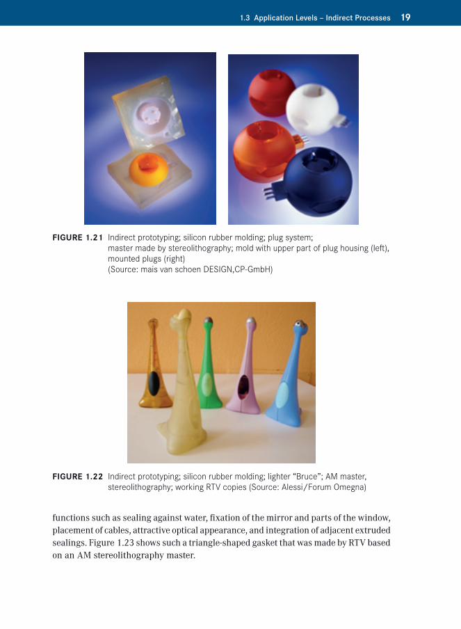
The internal evaluation of the table lighter “Bruce” designed by Stefano Giovannio in 1998 was very important. As the lighter was operated after inserting a disposable lighter into the bottom while the flame exits through the mouth, easy and safe handling was required. As steel tooling was too expensive at this stage of product develop-ment, the test samples were made by RTV based on an AM stereolithography master. Figure 1.22 shows the stereolithography master (in the front) and some color variations with and without mechanism.
Prototype parts from soft materials, for example gaskets, often have a very complex shape. This is especially true for gaskets for car mirror fixation that must fulfill many
1.3 Application Levels – Indirect Processes 19
FIGure 1.21■ Indirect prototyping; silicon rubber molding; plug system; master made by stereolithography; mold with upper part of plug housing (left), mounted plugs (right) (Source: mais van schoen DESIGN,CP-GmbH)
FIGure 1.22■ Indirect prototyping; silicon rubber molding; lighter “Bruce”; AM master, stereolithography; working RTV copies (Source: Alessi/Forum Omegna)
functions such as sealing against water, fixation of the mirror and parts of the window, placement of cables, attractive optical appearance, and integration of adjacent extruded sealings. Figure 1.23 shows such a triangle-shaped gasket that was made by RTV based on an AM stereolithography master.

1 Basics, Definitions, and Application Levels20
FIGure 1.23■ Indirect prototyping; silicon rubber molding; triangle-shaped gasket for car mirror fixation (Source: CP GmbH)
1.3.2■ Indirect Tooling
Indirect tooling is based on the same copying procedures as all indirect processes (Fig. 1.24). It is not the goal to obtain a final part, but a tool that provides the basis for a small or medium size batch production of final (or series) parts or products.
FIGure 1.24■ AM: indirect processes; indirect tooling

1.3 Application Levels – Indirect Processes 21
In contrast to series tools made from tool steel, it can be made quickly and inexpensively. Like indirect prototyping, indirect tooling uses AM masters, thus avoiding milling, grinding, and EDM-processes. In contrast to silicon rubber molding, it must be usable for a larger number of parts made not only from plastics but from metals as well. Seen from this perspective, indirect tooling can be regarded as an element of rapid tooling, although it is not a layer oriented process.
As an example, Fig. 1.25 shows a mold for making wax patterns for lost wax casting. The mold is obtained from an AM master by counter-casting it in polyurethane, PUR, backed by an aluminum box. After the AM master is removed, the mold is used to process the required amount of wax pattern. The higher rigidity of the PUR material in combination with the backed up walls leads to a mold that delivers much more precise wax patterns than could be made by a soft silicon mold. In comparison to milled all-aluminum tools it is cheaper and has a much shorter lead time. This kind of mold can be used for a small series production of complex precision cast parts.
There are parts that cannot be evaluated as samples made by manual casting from thermoset prototyping material, but need to be made by plastic injection molding machines and from the final series material. Examples are plastic parts made of flame retarded materials. Therefore rigid molds are needed. To avoid traditional tooling, a suitable rigid mold can be cast from aluminum-filled epoxy using a stereolithography or polymer jetted master. Despite the material, the process resembles the RTV process.
FIGure 1.25■ Indirect tooling. PUR mold obtained from an AM master, partly open. Separated mold half with cast wax pattern for lost wax casting. PUR cavity (black) obtained from AM master. Back up system by aluminum walls (Source: BeNe)

1 Basics, Definitions, and Application Levels22
For improvement of sharp edged details, milled inserts can be used. This kind of tool is typically not cooled and shows just a few manually operated inserts that substitute the sliders. As a disadvantage, long cycle times have to be taken in consideration. In Fig. 1.26 both cast resin mold-halves can be seen before being inserted in the mold frames. The stereolithography master (light brown) as well as a set of molded parts (black) can be seen. A small series of parts has been made from HD-PE to be tested in the engine compartment of a passenger car.
1.3.3■ Indirect Manufacturing
Indirect manufacturing is based on AM masters as well. The goal is to obtain final (or series) parts with properties equal to traditionally manufactured (non-AM) products. Consequently, indirect manufacturing belongs to the application level “Manufactur-ing” (Fig. 1.27).
As an example for indirect manufacturing, Fig. 1.28 shows a six-cylinder combus-tion engine housing. It was produced as a one-of-a-kind part based on an AM master made from polystyrene by laser sintering. The scaled master was transformed into an aluminum part by evaporative pattern casting (also called full-mold casting), which is a process closely related to the lost-wax-casting process.
As a result, a series of identical engine housings is obtained. It can be used to optimize and verify the engine design, including fired test runs long before series molds are available, but also as a small series product, e.g., for racing. Whether this is an ap-propriate manufacturing method or not is not a technical but an economical question.
FIGure 1.26■ Indirect tooling. Rigid mold made from aluminum filled epoxy for injection molding of a set of series identical parts (black) based on stereolithography masters (light brown) (Source: Elprotec)

1.3 Application Levels – Indirect Processes 23
FIGure 1.27■ AM: application level: rapid manufacturing; sub-level: indirect manufacturing
FIGure 1.28■ Indirect manufacturing; combustion engine housing; AM master (left), laser sintering, polystyrene; aluminum casting, one-of-a-kind part (right) (Source: Grunewald)
The same process was used to make the air intake manifold of a combustion engine displayed in Fig. 1.29. It was made from aluminum by lost-wax casting. Like in Fig. 1.28, the master was obtained from laser sintering of polystyrene. The left part shows the subsequent surface treatment with wax, while the cast part is displayed on the right side.

1 Basics, Definitions, and Application Levels24
FIGure 1.29■ Indirect Manufacturing. Air intake manifold; AM master made from poly-styrene by laser sintering after surface treatment (left), aluminum casting, one-of-a-kind part (right) (Source: CP-GmbH)
FIGure 1.30■ Indirect manufacturing: Gear box for a racing car; AM master made from PMMA by 3D printing (left), aluminum casting, one-of-a-kind part (right) (Source: Voxeljet)
Another variation of this process is displayed in Fig. 1.30, showing that the 3D printing process of PMMA-type plastics provides precise castings as well. In the picture, a gear box for a racing car is displayed as a lost form along with the cast part.

1.4 Classes of Machines for Additive Manufacturing 25
■■ 1.4■ Classes of Machines for Additive Manufacturing
There is a wide variety of machines for additive manufacturing available on the market. They are loosely linked to the application levels but more or less independent from the AM process used.
1.4.1■ Fabricators and Others
In general, a machine used for layer oriented AM is called a “fabricator”, especially if it can make (fabricate) final parts. If it is only capable of making prototypes, some call it a “prototyper”. The trend is to call all types of layer oriented additive manufacturing machines “printers” or “3D printers”, often with a prefix like “personal”, “professional” or similar terms.
1.4.2■ Nomenclature of AM Machines
Actually a nomenclature is developing that roughly assigns all AM machines on the market to three categories or classes: fabbers, office machines, and shop floor machines (see Table 1.1 and Fig. 1.31).
As a common abbreviation “fabber” is used in particular to address a small, simple, and cheap machine. If a fabber is used by a private person or a group of private individu-als and operated from home or a co-working space, it is increasingly called “personal fabber” (PF).
An “office machine” can be operated in an office environment. That means it emits minimum noise, smell, and particles. The build material can be refilled by office staff and is typically delivered in cartridges. Operation is easy and part handling is simple, including post processing. The waste is disposable as normal office- or household waste.
A “shop floor” machine requires an industrial environment, including trained personnel and logistics. It is designed for high output and productivity, which means it can handle large amounts of material. Sometimes solvents and machines, e.g., for sand blasting, are needed for cleaning. Here, economic production is more important than simple operation.
While this three categories are more or less agreed upon, the terms used are varying depending on company strategies and tend to incorporate at least the word “printer”. In Table 1.1 this nomenclature is structured and dedicated to the application levels.

1 Basics, Definitions, and Application Levels26
TABLe 1.1■ Nomenclature for AM Machines and its Relationship to Application Levels
Names
Fabbers Office machines Shop floor machines
Also called:Personal fabricatorsPersonal fabbersPersonal printersPersonal 3D printers
Office printersProfessional printersProfessional 3D printers
Production machinesProduction printersProduction 3D printers
Application
Semi professional or private use at home office
Professional use in the office or in a workshop
Professional use in production or professional job-shop
Application Level
Rapid prototyping Rapid prototyping Rapid manufacturing
Solid imaging Functional prototyping Direct prototyping
Concept modeling Masters for secondary rapid prototyping processes
Direct tooling
3D Systems BFB 3000
Stratasys Fortus 900 mc
Objet Eden 500 V
Fabbers Office machines Shop floor machines Personal Professional Production 3D printers 3D printers 3D printers
FIGure 1.31■ Nomenclature for AM machines and its relation to the application levels; examples
This categorization does not directly depend on the AM processes the machines are based on and which are discussed in Chapter 2.
Nevertheless there is a loose interdependency between AM process and the applica-tion level. A typical machine for each category is displayed on Fig. 1.31. The machines

1.5 Conclusion 27
displayed show the typical appearance of machines belonging to one of the three catego-ries fabbers, office machines, and shop floor machines. Of course, the machines shown here are just examples. Many others are discussed in Chapter 2 and are displayed in Figs. 2-26 to 2-28, once the basic principles are discussed.
Seen from the operator’s point of view, AM machines can be categorized according to the professional skills needed for operation as well as according to their prizing. This is done in Table 1.2 which is linked to the definitions above and the environment needed
■■ 1.5■ Conclusion
The discussion of the applications of additive manufacturing proves that today all levels of applications and all branches already benefit from the capabilities of AM. The definitions support a professional discussion. In practice it is particularly important to distinguish between the different application levels. Disappointments often result because the users do not properly define their expectations.
The examples underline that various AM processes can be used, sometimes even al-ternatively, to meet the user’s needs. To take advantage of this fact, the different AM processes that are commercially available are presented and discussed in Chapter 2.
Today’s restrictions, such as a limited variety of materials, poor surface quality, or a far too slow performance of AM production processes will be overcome quickly.
TABLe 1.2■Categorization of AM Machines According to the Required Infrastructure, Professional Skills for Operation, and Average Prizing
Class of Machine Operator Infrastructure Prizing
Fabbers Everyone with basic skills to operate a personal computer
Despite a kitchen table no infrastructure is required
From under €/$ 1.000 to €/$ 20.000
Office Printers People who profes-sionally work with different types of 3D CAD
No special infrastructure is indispensable. A separate office room helps to handle the material and the parts and keeps away the (not really bothering) noise.
From €/$ 15.000 to €/$ 140.000
Shop Floor Machines
Technicians of the fabrication department
A shop floor environment is needed.
From €/$ 120.000 to €/$ 800.000 and up