
Underground expansion of Drents Museum-005
26
18/02/2013 1 Underground Expansion of Drents Museum The use of PLAXIS in pre- and postdiction analyses PLAXIS PDC meeting February 15, 2013 Marco Peters 2 Contents Project description Soil investigation Excavation methods Excavation methods Retaining wall types PLAXIS prediction analysis PLAXIS postdiction analysis Why prediction analysis? – To predict the displacements of the monumental buildings during excavations – To determine design and phasing in order to respect the displacement requirements Why postdiction analysis? – To verify the design principles and assumptions – To control and/or reduce risks and to optimise where possible
-
Upload
marco-peters -
Category
Documents
-
view
79 -
download
0
Transcript of Underground expansion of Drents Museum-005
18/02/2013
1
Underground Expansion of Drents Museum
The use of PLAXIS in pre- and postdiction analyses
PLAXIS PDC meeting
February 15, 2013
Marco Peters
2
Contents
� Project description
� Soil investigation
� Excavation methods� Excavation methods
� Retaining wall types
� PLAXIS prediction analysis
� PLAXIS postdiction analysis
� Why prediction analysis?
– To predict the displacements of the monumental buildings during excavations
– To determine design and phasing in order to respect the displacement requirements
� Why postdiction analysis?
– To verify the design principles and assumptions
– To control and/or reduce risks and to optimise where possible
18/02/2013
2
3
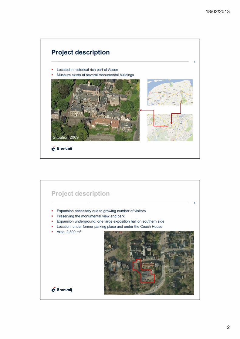
Project description
� Located in historical rich part of Assen
� Museum exists of several monumental buildings
Situation 2009
4
Project description
� Expansion necessary due to growing number of visitors
� Preserving the monumental view and park
� Expansion underground: one large exposition hall on southern side� Expansion underground: one large exposition hall on southern side
� Location: under former parking place and under the Coach House
� Area: 2,500 m²
18/02/2013
3
5
Project description
� Underground connection to main building (Bailiff’s House)
� Indoor excavation
� Exposition hall under monumental Coach House
� Temporally relocation of the Coach House
Original crack of course… Original crack of course… Original crack of course… Original crack of course… (also gas extraction??)(also gas extraction??)(also gas extraction??)(also gas extraction??)
6
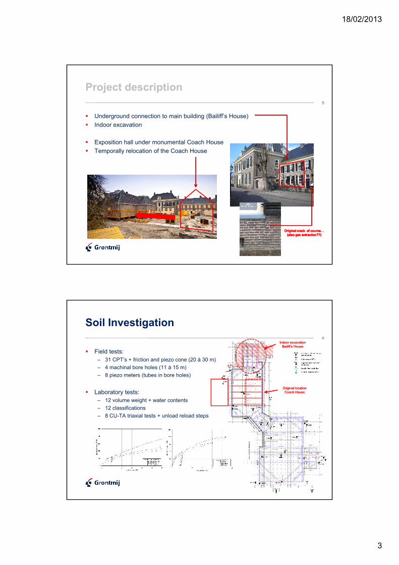
Soil Investigation
� Field tests:
– 31 CPT’s + friction and piezo cone (20 à 30 m)
– 4 machinal bore holes (11 à 15 m)
Indoor excavation Indoor excavation Bailiff’s HouseBailiff’s House
– 4 machinal bore holes (11 à 15 m)
– 8 piezo meters (tubes in bore holes)
� Laboratory tests:
– 12 volume weight + water contents
– 12 classifications
– 8 CU-TA triaxial tests + unload reload steps
Original location Original location Coach HouseCoach House
18/02/2013
4
7
Soil Investigation
Soil type (DKM 23)Top
[m+NAP]
Sand, moderate, slightly clayey +10.0Sand, moderate, slightly clayey +10.0
Boulder Clay (Keileem) +8.5
Sand, loose/moderate +7.2
Sand, dense with gravel +5.0
Pot Clay +1.5
Sand, moderate -1.5
Pot Clay -5.5
Sand, dense with gravel -9.5
Underground Underground Underground Underground obstacles?obstacles?obstacles?obstacles?
8
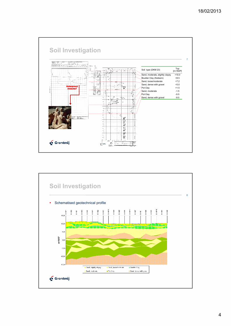
Soil Investigation
� Schematised geotechnical profile
18/02/2013
5
9
Soil Investigation
γ γ φ
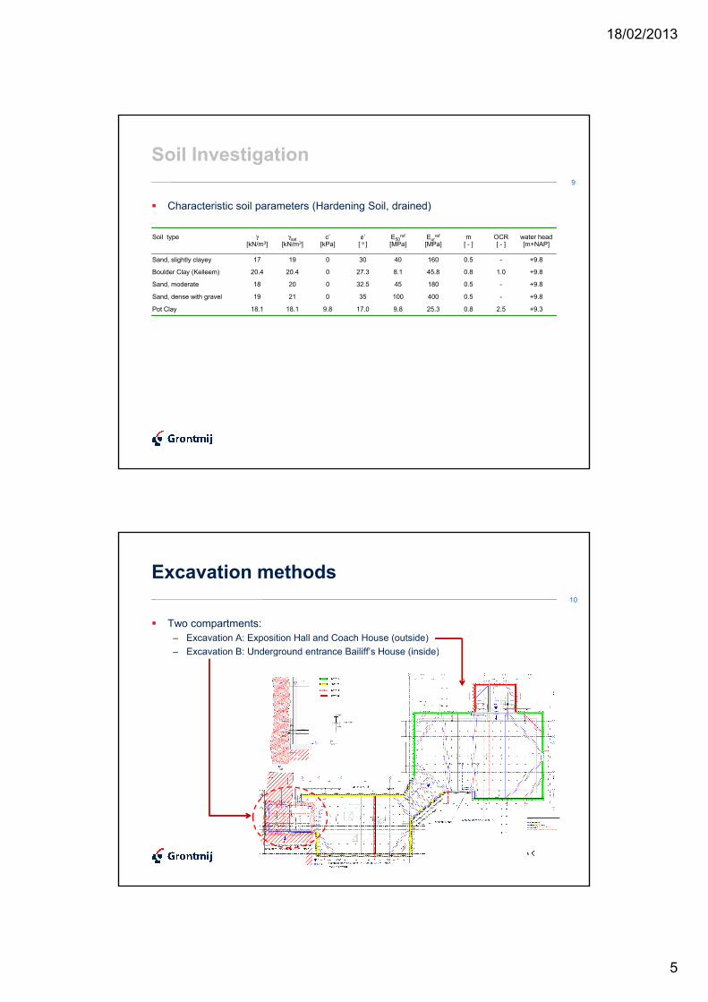
� Characteristic soil parameters (Hardening Soil, drained)
Soil type γ[kN/m3]
γsat[kN/m3]
c’[kPa]
φ’[ o ]
E50ref
[MPa]Eur
ref
[MPa]m[ - ]
OCR[ - ]
water head[m+NAP]
Sand, slightly clayey 17 19 0 30 40 160 0.5 - +9.8
Boulder Clay (Keileem) 20.4 20.4 0 27.3 8.1 45.8 0.8 1.0 +9.8
Sand, moderate 18 20 0 32.5 45 180 0.5 - +9.8
Sand, dense with gravel 19 21 0 35 100 400 0.5 - +9.8
Pot Clay 18.1 18.1 9.8 17.0 9.8 25.3 0.8 2.5 +9.3
10
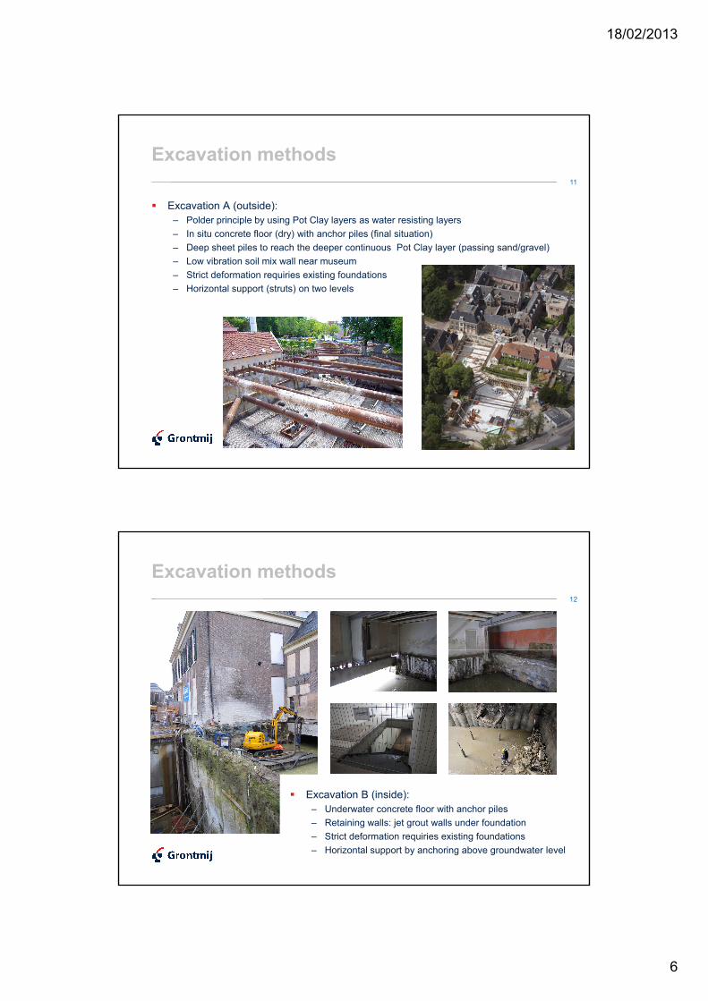
Excavation methods
� Two compartments:
– Excavation A: Exposition Hall and Coach House (outside)
– Excavation B: Underground entrance Bailiff’s House (inside)– Excavation B: Underground entrance Bailiff’s House (inside)
18/02/2013
6
11
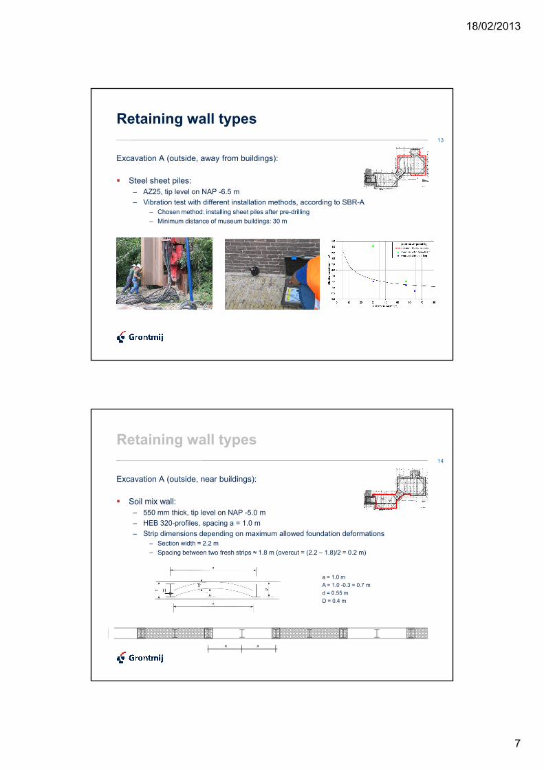
Excavation methods
� Excavation A (outside):
– Polder principle by using Pot Clay layers as water resisting layers
– In situ concrete floor (dry) with anchor piles (final situation)– In situ concrete floor (dry) with anchor piles (final situation)
– Deep sheet piles to reach the deeper continuous Pot Clay layer (passing sand/gravel)
– Low vibration soil mix wall near museum
– Strict deformation requiries existing foundations
– Horizontal support (struts) on two levels
12
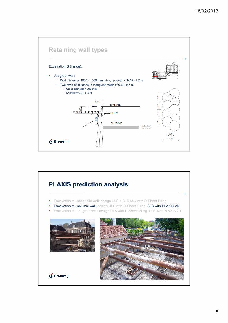
Excavation methods
� Excavation B (inside):
– Underwater concrete floor with anchor piles
– Retaining walls: jet grout walls under foundation
– Strict deformation requiries existing foundations
– Horizontal support by anchoring above groundwater level
18/02/2013
7
13
Retaining wall types
Excavation A (outside, away from buildings):
� Steel sheet piles: � Steel sheet piles:
– AZ25, tip level on NAP -6.5 m
– Vibration test with different installation methods, according to SBR-A
– Chosen method: installing sheet piles after pre-drilling
– Minimum distance of museum buildings: 30 m
14
Retaining wall types
Excavation A (outside, near buildings):
� Soil mix wall:� Soil mix wall:
– 550 mm thick, tip level on NAP -5.0 m
– HEB 320-profiles, spacing a = 1.0 m
– Strip dimensions depending on maximum allowed foundation deformations
– Section width ≈ 2.2 m
– Spacing between two fresh strips ≈ 1.8 m (overcut = (2.2 – 1.8)/2 = 0.2 m)
a = 1.0 m
A = 1.0 -0.3 = 0.7 m
d = 0.55 md = 0.55 m
D = 0.4 m
a a
18/02/2013
8
15
Retaining wall types
Excavation B (inside):
� Jet grout wall:� Jet grout wall:
– Wall thickness 1000 - 1500 mm thick, tip level on NAP -1.7 m
– Two rows of columns in triangular mesh of 0.6 – 0.7 m
– Grout diameter = 900 mm
– Overcut = 0.2 – 0.3 m
16
PLAXIS prediction analysis
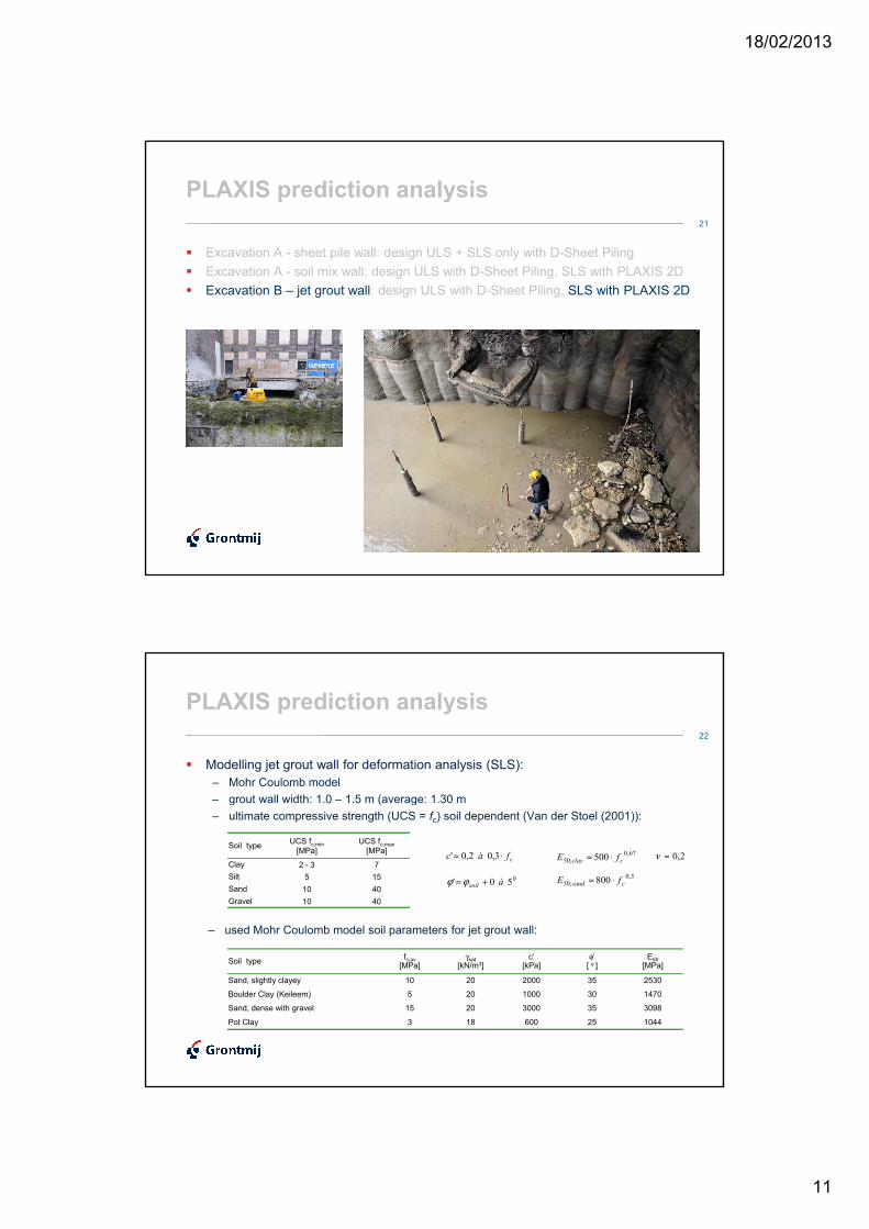
� Excavation A - sheet pile wall: design ULS + SLS only with D-Sheet Piling
� Excavation A - soil mix wall: design ULS with D-Sheet Piling, SLS with PLAXIS 2D
� Excavation B – jet grout wall: design ULS with D-Sheet Piling, SLS with PLAXIS 2D � Excavation B – jet grout wall: design ULS with D-Sheet Piling, SLS with PLAXIS 2D
18/02/2013
9
17
PLAXIS prediction analysis
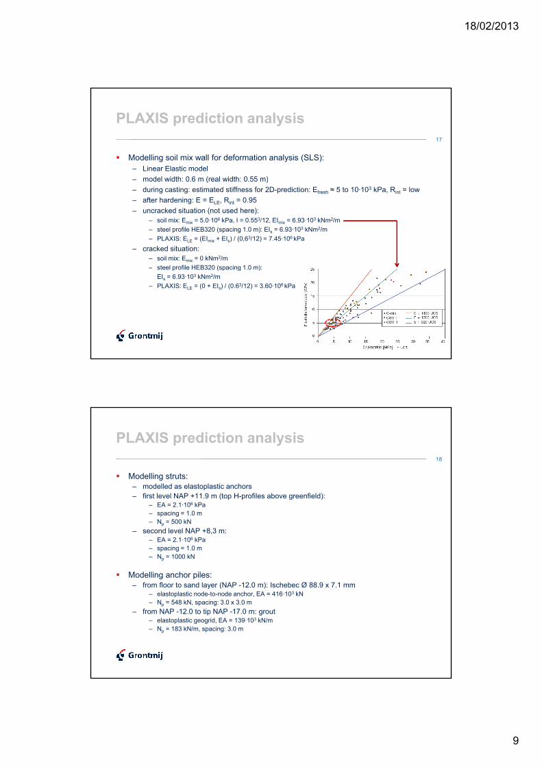
� Modelling soil mix wall for deformation analysis (SLS):
– Linear Elastic model
– model width: 0.6 m (real width: 0.55 m)– model width: 0.6 m (real width: 0.55 m)
– during casting: estimated stiffness for 2D-prediction: Efresh ≈ 5 to 10·103 kPa, Rint = low
– after hardening: E = ELE, Rint = 0.95
– uncracked situation (not used here):
– soil mix: Emix = 5.0·106 kPa, I = 0.553/12, EImix = 6.93·10
3 kNm2/m
– steel profile HEB320 (spacing 1.0 m): EIs = 6.93·103 kNm2/m
– PLAXIS: ELE = (EImix + EIs) / (0,63/12) = 7.45·106 kPa
– cracked situation:
– soil mix: Emix = 0 kNm2/m
– steel profile HEB320 (spacing 1.0 m): – steel profile HEB320 (spacing 1.0 m):
EIs = 6.93·103 kNm2/m
– PLAXIS: ELE = (0 + EIs) / (0.63/12) = 3.60·106 kPa
18
PLAXIS prediction analysis
� Modelling struts:
– modelled as elastoplastic anchors
– first level NAP +11.9 m (top H-profiles above greenfield):– first level NAP +11.9 m (top H-profiles above greenfield):– EA = 2.1·106 kPa
– spacing = 1.0 m
– Np = 500 kN
– second level NAP +8,3 m:– EA = 2.1·106 kPa
– spacing = 1.0 m
– Np = 1000 kN
� Modelling anchor piles:
– from floor to sand layer (NAP -12.0 m): Ischebec Ø 88.9 x 7.1 mm– from floor to sand layer (NAP -12.0 m): Ischebec Ø 88.9 x 7.1 mm– elastoplastic node-to-node anchor, EA = 416·103 kN
– Np = 548 kN, spacing: 3.0 x 3.0 m
– from NAP -12.0 to tip NAP -17.0 m: grout – elastoplastic geogrid, EA = 139·103 kN/m
– Np = 183 kN/m, spacing: 3.0 m

18/02/2013
10
19
PLAXIS prediction analysis
(1004)(1005) (1004)(1005)
20
PLAXIS prediction analysis
� Prediction results vertical displacement foundation near soil mix wall
(1004)(1005)
18/02/2013
11
21
PLAXIS prediction analysis
� Excavation A - sheet pile wall: design ULS + SLS only with D-Sheet Piling
� Excavation A - soil mix wall: design ULS with D-Sheet Piling, SLS with PLAXIS 2D
� Excavation B – jet grout wall: design ULS with D-Sheet Piling, SLS with PLAXIS 2D� Excavation B – jet grout wall: design ULS with D-Sheet Piling, SLS with PLAXIS 2D
22
PLAXIS prediction analysis
� Modelling jet grout wall for deformation analysis (SLS):
– Mohr Coulomb model
– grout wall width: 1.0 – 1.5 m (average: 1.30 m– grout wall width: 1.0 – 1.5 m (average: 1.30 m
– ultimate compressive strength (UCS = fc) soil dependent (Van der Stoel (2001)):
2,0≈ν
– used Mohr Coulomb model soil parameters for jet grout wall:
Soil typeUCS fc;min
[MPa]UCS fc;max
[MPa]
Clay 2 - 3 7
Silt 5 15
Sand 10 40
Gravel 10 40
cfàc ⋅≈ 3,0 2,0'
05 0' àsoil +≈ ϕϕ
5,0
;50 800 csand fE ⋅≈
67,0
;50 500 cclay fE ⋅≈
Soil typefc;av[MPa]
γsat[kN/m3]
c’[kPa]
φ’[ o ]
E50
[MPa]
Sand, slightly clayey 10 20 2000 35 2530
Boulder Clay (Keileem) 5 20 1000 30 1470
Sand, dense with gravel 15 20 3000 35 3098
Pot Clay 3 18 600 25 1044
18/02/2013
12
23
PLAXIS prediction analysis
� Modelling anchors:
– anchor (north+east) NAP +9.0 m (lsteel ≈ 6 m): Ischebec Ø 30 x 11 mm– elastoplastic node-to-node anchor, EA = 95·103 kN– elastoplastic node-to-node anchor, EA = 95·10 kN
– Np = 260 kN, spacing: 1,4 m
– anchor (west) NAP +9.8 m (lsteel ≈ 7 m): Ischebec Ø 40 x 20 mm– elastoplastic node-to-node anchor, EA = 150·103 kN
– Np = 425 kN, spacing: 1,4 m
– grout (lgrout ≈ 5 m): Ø 120 mm– elastoplastic geogrid, EA = 68·103 kN/m
– Np = 150 kN/m, spacing: 1.4 m
� Modelling anchor piles:
– from floor to sand layer (NAP -12.0 m): Ischebec Ø 88.9 x 7.1 mm– from floor to sand layer (NAP -12.0 m): Ischebec Ø 88.9 x 7.1 mm– elastoplastic node-to-node anchor, EA = 416·103 kN
– Np = 548 kN, spacing: 2.2 x 2.2 m
– from NAP -12.0 to tip NAP -17.0 m: grout – elastoplastic geogrid, EA = 190·103 kN/m
– Np = 250 kN/m, spacing: 2.2 m
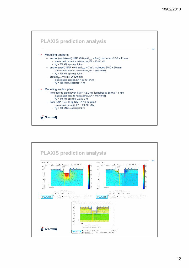
24
PLAXIS prediction analysis
(1005) (1005)
18/02/2013
13
25
PLAXIS prediction analysis
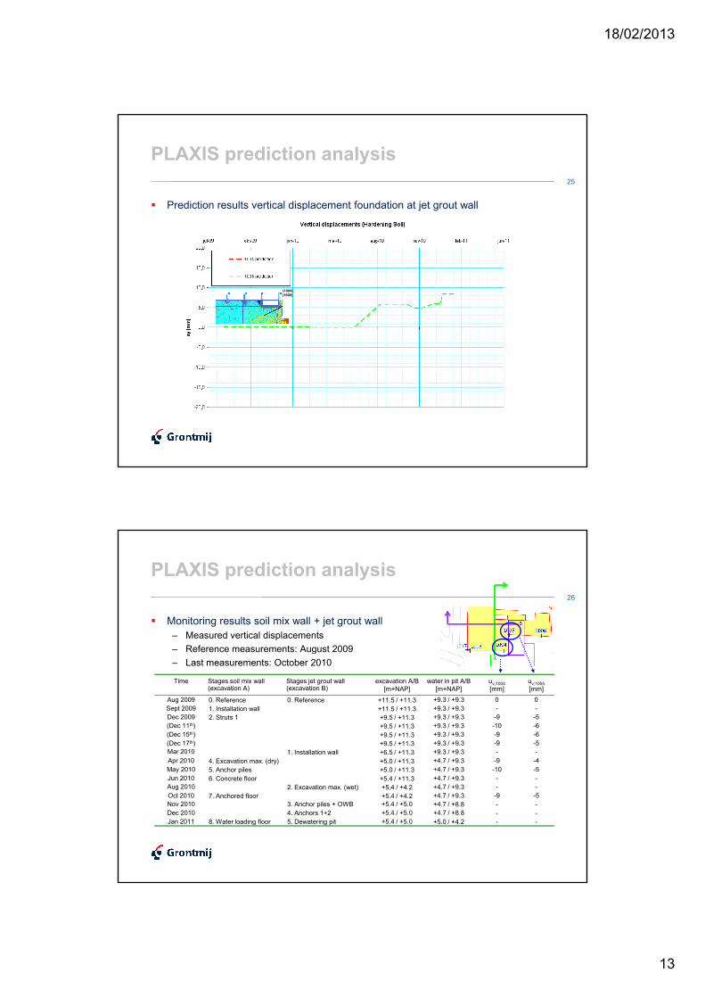
� Prediction results vertical displacement foundation at jet grout wall
(1004)
(1005)
26
PLAXIS prediction analysis
� Monitoring results soil mix wall + jet grout wall
– Measured vertical displacements
– Reference measurements: August 2009– Reference measurements: August 2009
– Last measurements: October 2010
Time Stages soil mix wall(excavation A)
Stages jet grout wall(excavation B)
excavation A/B
[m+NAP]
water in pit A/B
[m+NAP]
uv;1004[mm]
uv;1005[mm]
Aug 2009 0. Reference 0. Reference +11.5 / +11.3 +9.3 / +9.3 0 0
Sept 2009 1. Installation wall +11.5 / +11.3 +9.3 / +9.3 - -
Dec 2009 2. Struts 1 +9.5 / +11.3 +9.3 / +9.3 -9 -5
(Dec 11th) +9.5 / +11.3 +9.3 / +9.3 -10 -6
(Dec 15th) +9.5 / +11.3 +9.3 / +9.3 -9 -6
(Dec 17th) +9.5 / +11.3 +9.3 / +9.3 -9 -5
Mar 2010 1. Installation wall +6.5 / +11.3 +9.3 / +9.3 - -
Apr 2010 4. Excavation max. (dry) +5.0 / +11.3 +4.7 / +9.3 -9 -4
May 2010 5. Anchor piles +5.0 / +11.3 +4.7 / +9.3 -10 -5
Jun 2010 6. Concrete floor +5.4 / +11.3 +4.7 / +9.3 - -
Aug 2010 2. Excavation max. (wet) +5.4 / +4.2 +4.7 / +9.3 - -
Oct 2010 7. Anchored floor +5.4 / +4.2 +4.7 / +9.3 -9 -5
Nov 2010 3. Anchor piles + OWB +5.4 / +5.0 +4.7 / +8.8 - -
Dec 2010 4. Anchors 1+2 +5.4 / +5.0 +4.7 / +8.8 - -
Jan 2011 8. Water loading floor 5. Dewatering pit +5.4 / +5.0 +5.0 / +4.2 - -
18/02/2013
14
27
PLAXIS prediction analysis
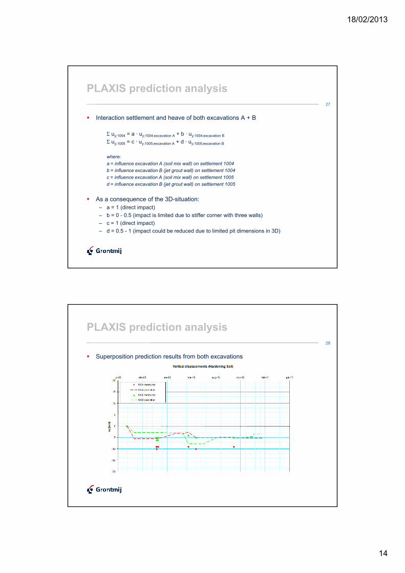
� Interaction settlement and heave of both excavations A + B
Σ u = a · u + b · uΣ uy;1004 = a · uy;1004;excavation A + b · uy;1004;excavation B
Σ uy;1005 = c · uy;1005;excavation A + d · uy;1005;excavation B
where:
a = influence excavation A (soil mix wall) on settlement 1004
b = influence excavation B (jet grout wall) on settlement 1004
c = influence excavation A (soil mix wall) on settlement 1005
d = influence excavation B (jet grout wall) on settlement 1005
� As a consequence of the 3D-situation:� As a consequence of the 3D-situation:
– a = 1 (direct impact)
– b = 0 - 0.5 (impact is limited due to stiffer corner with three walls)
– c = 1 (direct impact)
– d = 0.5 - 1 (impact could be reduced due to limited pit dimensions in 3D)
28
PLAXIS prediction analysis
� Superposition prediction results from both excavations
18/02/2013
15
29
PLAXIS prediction analysis
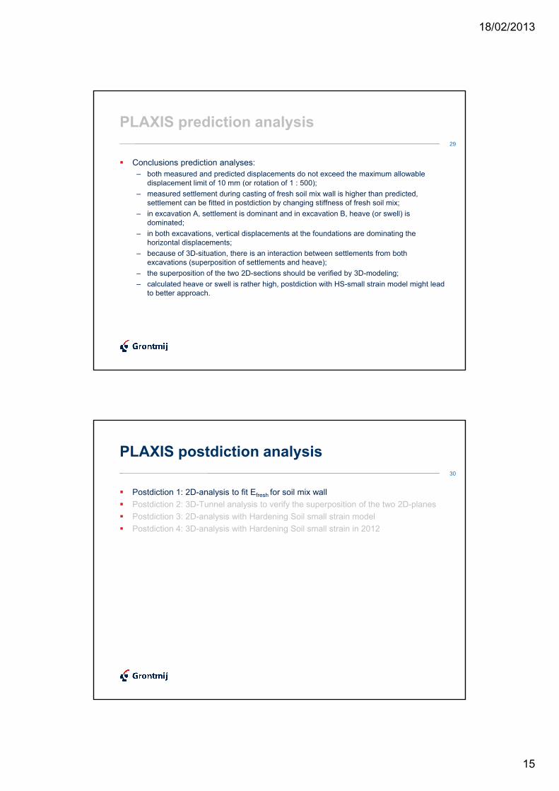
� Conclusions prediction analyses:
– both measured and predicted displacements do not exceed the maximum allowable
displacement limit of 10 mm (or rotation of 1 : 500);displacement limit of 10 mm (or rotation of 1 : 500);
– measured settlement during casting of fresh soil mix wall is higher than predicted,
settlement can be fitted in postdiction by changing stiffness of fresh soil mix;
– in excavation A, settlement is dominant and in excavation B, heave (or swell) is
dominated;
– in both excavations, vertical displacements at the foundations are dominating the
horizontal displacements;
– because of 3D-situation, there is an interaction between settlements from both
excavations (superposition of settlements and heave);
– the superposition of the two 2D-sections should be verified by 3D-modeling;– the superposition of the two 2D-sections should be verified by 3D-modeling;
– calculated heave or swell is rather high, postdiction with HS-small strain model might lead
to better approach.
30
PLAXIS postdiction analysis
� Postdiction 1: 2D-analysis to fit Efresh for soil mix wall
� Postdiction 2: 3D-Tunnel analysis to verify the superposition of the two 2D-planes
� Postdiction 3: 2D-analysis with Hardening Soil small strain model� Postdiction 3: 2D-analysis with Hardening Soil small strain model
� Postdiction 4: 3D-analysis with Hardening Soil small strain in 2012
18/02/2013
16
31
PLAXIS postdiction analysis #1
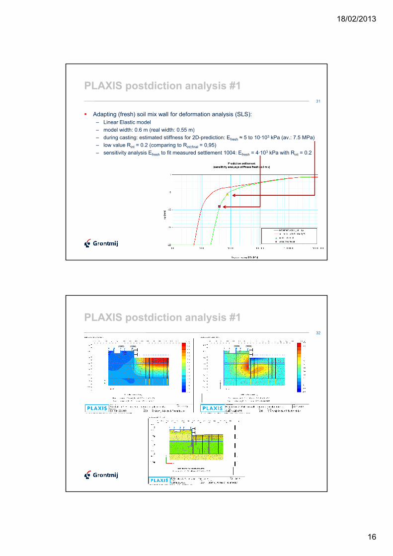
� Adapting (fresh) soil mix wall for deformation analysis (SLS):
– Linear Elastic model
– model width: 0.6 m (real width: 0.55 m)– model width: 0.6 m (real width: 0.55 m)
– during casting: estimated stiffness for 2D-prediction: Efresh ≈ 5 to 10·103 kPa (av.: 7.5 MPa)
– low value Rint = 0.2 (comparing to Rint;final = 0,95)
– sensitivity analysis Efresh to fit measured settlement 1004: Efresh = 4·103 kPa with Rint = 0.2
32
PLAXIS postdiction analysis #1
(1004)(1005) (1004)(1005)

18/02/2013
17
33
PLAXIS postdiction analysis #1
� Superposition postdiction results from both excavations
34
PLAXIS postdiction analysis #2
� Postdiction 1: 2D-analysis to fit Efresh for soil mix wall
� Postdiction 2: 3D-Tunnel analysis to verify the superposition of the two 2D-planes
� Postdiction 3: 2D-analysis with Hardening Soil small strain model� Postdiction 3: 2D-analysis with Hardening Soil small strain model
� Postdiction 4: 3D-analysis with Hardening Soil small strain in 2012
18/02/2013
18
35
PLAXIS postdiction analysis #2
� Modelling in 3D-Tunnel (2010):
– verifying superposition of both excavations
– calculation only with Hardening Soil (HS-small strain was not available yet)– calculation only with Hardening Soil (HS-small strain was not available yet)
– excavations only rectangular
36
PLAXIS postdiction analysis #2
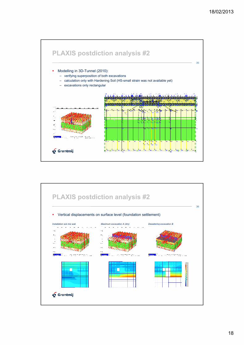
� Vertical displacements on surface level (foundation settlement)
Installation soil mix wall Maximum excavation A (dry) Dewatering excavation B Installation soil mix wall Maximum excavation A (dry) Dewatering excavation B
18/02/2013
19
37
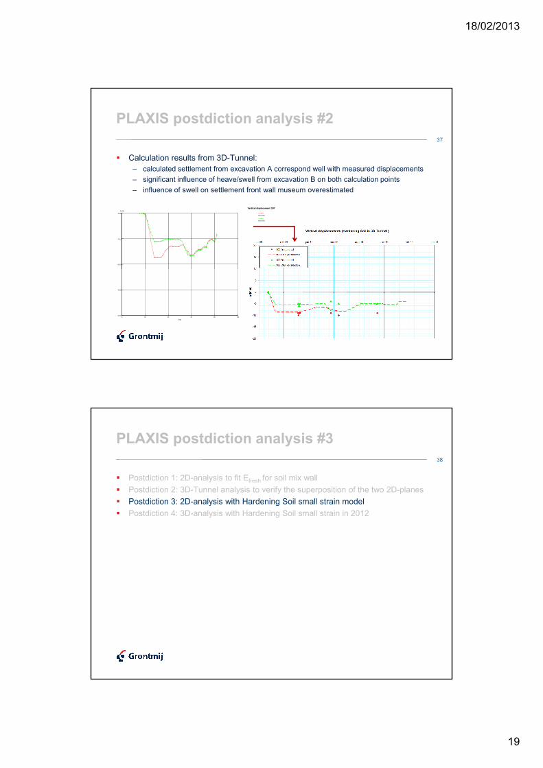
PLAXIS postdiction analysis #2
� Calculation results from 3D-Tunnel:
– calculated settlement from excavation A correspond well with measured displacements
– significant influence of heave/swell from excavation B on both calculation points
-0,010
-5,e-3
0,000
Uy [m]
Vertical displacement 3DT
Point 1004
Point 1005
– significant influence of heave/swell from excavation B on both calculation points
– influence of swell on settlement front wall museum overestimated
0 20 40 60 80 100-0,020
-0,015
Step
38
PLAXIS postdiction analysis #3
� Postdiction 1: 2D-analysis to fit Efresh for soil mix wall
� Postdiction 2: 3D-Tunnel analysis to verify the superposition of the two 2D-planes
� Postdiction 3: 2D-analysis with Hardening Soil small strain model� Postdiction 3: 2D-analysis with Hardening Soil small strain model
� Postdiction 4: 3D-analysis with Hardening Soil small strain in 2012
18/02/2013
20
39
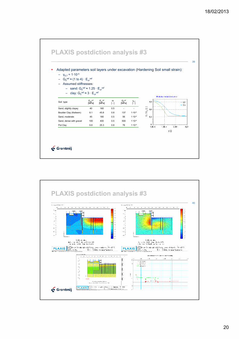
PLAXIS postdiction analysis #3
� Adapted parameters soil layers under excavation (Hardening Soil small strain):
– γ0,7 = 1·10-4
– G ref ≈ (1 to 4) · E ref
Soil typeE50
ref
[MPa]Eur
ref
[MPa]m[ - ]
G0ref
[MPa]γ0,7[ - ]
Sand, slightly clayey 40 160 0.5 - -
Boulder Clay (Keileem) 8.1 45.8 0.8 137 1·10-4
Sand, moderate 45 180 0.5 56 1·10-4
– G0ref ≈ (1 to 4) · Eur
ref
– Assumed stiffnesses:
– sand: G0ref ≈ 1.25 · Eur
ref
– clay: G0ref ≈ 3 · Eur
ref
Sand, dense with gravel 100 400 0.5 500 1·10-4
Pot Clay 9.8 25.3 0.8 76 1·10-4
40
PLAXIS postdiction analysis #3
(1004)(1005) (1004)(1005)
18/02/2013
21
41
PLAXIS postdiction analysis #3
(1005) (1005)
42
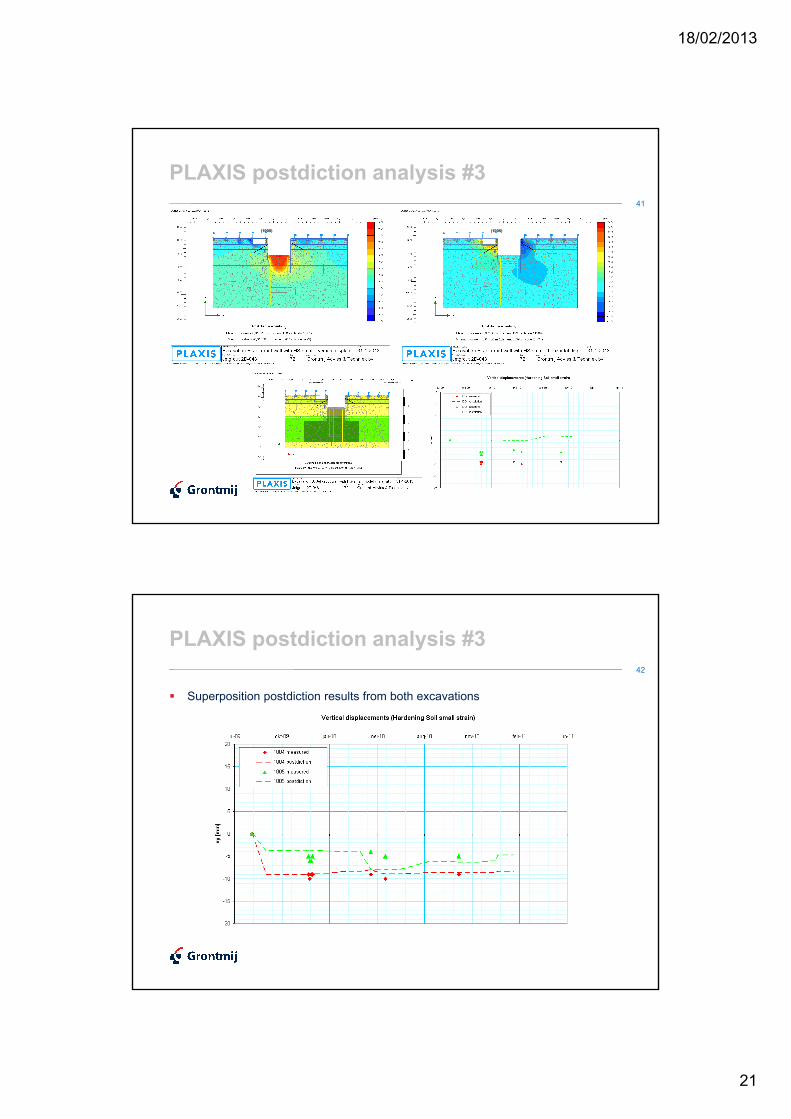
PLAXIS postdiction analysis #3
� Superposition postdiction results from both excavations
18/02/2013
22
43
PLAXIS postdiction analysis #4
� Postdiction 1: 2D-analysis to fit Efresh for soil mix wall
� Postdiction 2: 3D Tunnel-analysis to verify the superposition of the two 2D-planes
� Postdiction 3: 2D-analysis with Hardening Soil small strain model� Postdiction 3: 2D-analysis with Hardening Soil small strain model
� Postdiction 4: 3D-analysis with Hardening Soil small strain in 3D-2012
44
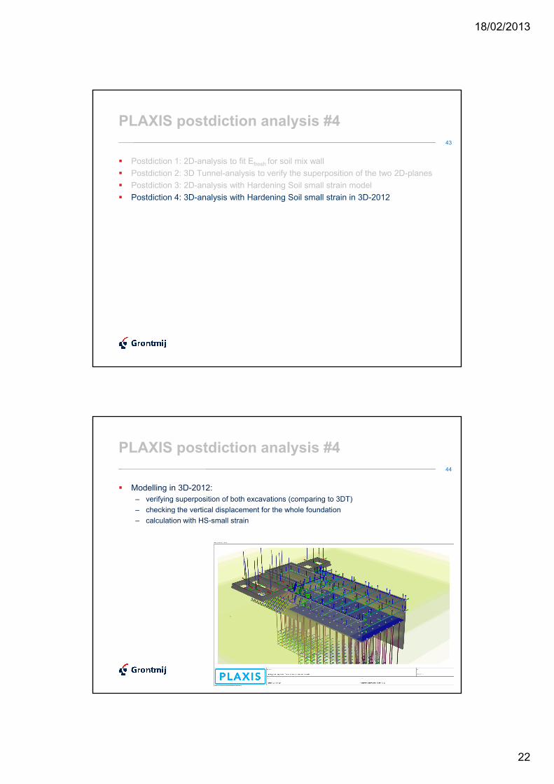
PLAXIS postdiction analysis #4
� Modelling in 3D-2012:
– verifying superposition of both excavations (comparing to 3DT)
– checking the vertical displacement for the whole foundation– checking the vertical displacement for the whole foundation
– calculation with HS-small strain

18/02/2013
23
45
46
PLAXIS postdiction analysis #4
� Vertical displacements on surface level (foundation settlement)
Installation soil mix wall Maximum excavation A (dry)Installation soil mix wall Maximum excavation A (dry)
18/02/2013
24
47
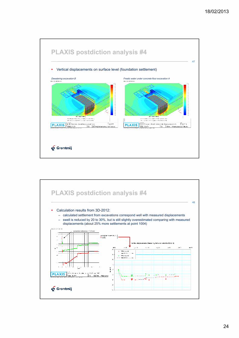
PLAXIS postdiction analysis #4
� Vertical displacements on surface level (foundation settlement)
Dewatering excavation B Freatic water under concrete floor excavation A Dewatering excavation B Freatic water under concrete floor excavation A
48
PLAXIS postdiction analysis #4
� Calculation results from 3D-2012:
– calculated settlement from excavations correspond well with measured displacements
– swell is reduced by 20 to 30%, but is still slightly overestimated comparing with measured – swell is reduced by 20 to 30%, but is still slightly overestimated comparing with measured
displacements (about 25% more settlements at point 1004)
correction reference = 1,5 mm
18/02/2013
25
49
Conclusions PLAXIS pre- and postdictions
� Conclusions 2D-and 3D-analyses:
– Both measured and predicted displacements do not exceed the maximum allowable displacement limit of 10 mm (or relative rotation of 1 : 500).
– Effect of fresh soil mix dominates the settlement, a realistic (average) stiffness is essential – Effect of fresh soil mix dominates the settlement, a realistic (average) stiffness is essential to make a proper prediction.
– Verification superposition of two 2D-plane strain with 3D-analyses is satisfactory.
– Modelling with HS-small leads to better approach, especially for the effect of excavation B.
– Assumed values for G0ref seem to be proper values (after some sensitivity analyses).
– With HS-small strain model, maximum heave or swell is reduced by 20 à 30%.
– Swell is slightly overestimated (but other effects might have led to measured settlement).
� Recommendations:
– Installation of soil mix walls might lead to small but significant displacements. – Installation of soil mix walls might lead to small but significant displacements.
– To define Go from CU-tests more punctually, smaller strains have to be investigated.
– Further analysis of swell in general is recommended.(special attention to undrained and consolidation behaviour might be useful during the different stages, especially to make distinction to different swell mechanisms - initial volume-constant and elastic swell, primary swell with degree of consolidation, secondary swell etc. - this is one of the investigation topics of
CUR committee C202).
50
Project team
� Client: Provincie Drenthe
� Project developer: Draaijer & Partners
� Main contractor: Geveke Bouw BV (TBI)� Main contractor: Geveke Bouw BV (TBI)
� Structural design: IB Wassenaar BV
� Geotechnical design & consult: Grontmij Nederland BV
� Contractor underground constructions: Franki Foundations Group (Besix)
� Soil investigation: Grontmij Terreinonderzoek & IJB Geotechniek BV
� Laboratory investigation: Fugro Materiaalkundig Laboratorium
� Sheet pile vibration analysis: Sterk Heiwerken
� Monitoring: Mug Ingenieursbureau BV
� Architect: Erick van Egeraat (DbEVE)
18/02/2013
26
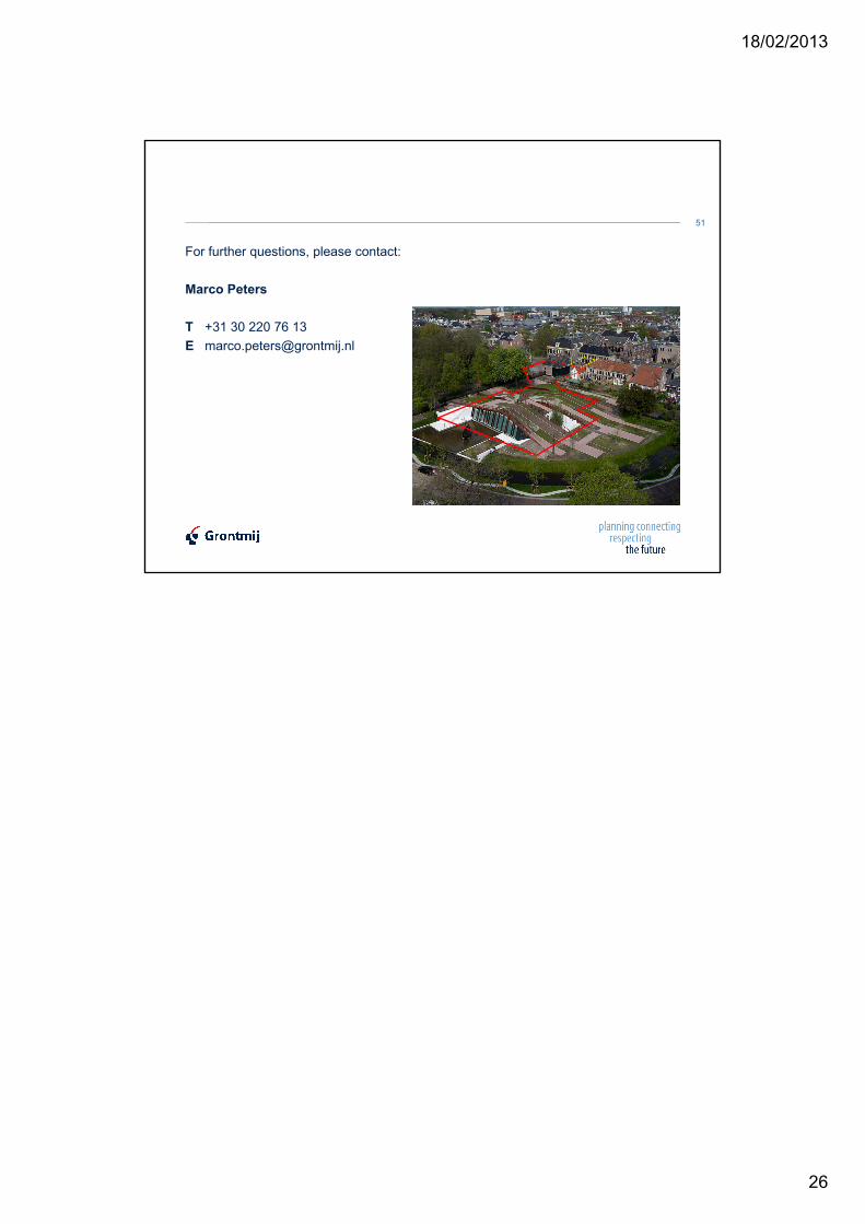
For further questions, please contact:
Marco Peters
51
Marco Peters
T +31 30 220 76 13