UNDERGROUND DRAINAGE &SEWER SYSTEM FILES/7_ Paling...UNDERGROUND DRAINAGE & SEWER SYSTEM ///...
52
UNDERG ROUND DRAINAGE & SEWER SYSTEM PIPE SYSTEMS SUITABLE FOR BUILDINGS, HOUSES AND CIVIL CONSTRUCTION PURPOSES.
Transcript of UNDERGROUND DRAINAGE &SEWER SYSTEM FILES/7_ Paling...UNDERGROUND DRAINAGE & SEWER SYSTEM ///...
UNDERGROUNDDRAINAGE &SEWER
SYSTEM
P I P E S Y S T E M SSUITABLE FOR BUILDINGS,
HOUSES AND CIVIL CONSTRUCTION PURPOSES.

CONTENTS

SYSTEM FEATURES & ADVANTAGES
22 Features, Advantages & Application
ACCREDITATION& SPECIFICATION
4 4 Quality&Certification
5 Specifications&Standards
PIPES& FITTINGS DETAILS
7 7 Underground Pipes
8 Underground Fittings
• Non-Return Valve
• Special Mechanical Connection-Easy Clip
• Inspection Chamber
INSTALLATION
14 41 Installation Guideline
44 System Layout
46 FAQs
ABOUT US
47 47 About Paling Industries
47 About Aliaxis
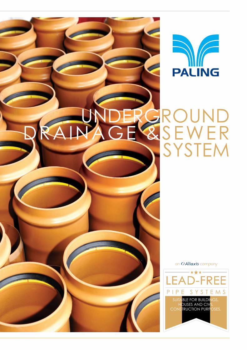
FEATURES• Highqualityoffinishwithsmoothinternalandexternal
surface
• Providelowcoefficientofflowfriction
• Excellent resistance to chemicals and gases naturally foundinsewage
• Extensive size range to suit all installation needs
• CertifiedISO9001bySIRIM
• ComplieswithBSEN1401andMS979.SPANlisted
ADVANTAGES• High Internal Smoothness
• High Impact Resistance
• Abrasion and Shock Resistance
• Algae and Bacteria Resistance
• Abilitytoaccommodatedeformationwithout structural damage
APPLICATIONPaling Underground Pipes and Fittings are used for domestic drains, and public and private sewers
UNDERGROUND DRAINAGE & SEWER SYSTEM
PRODUCT RANGE
UNDERGROUND DRAINAGE & SEWER SYSTEM /// FEATURES & ADVANTAGES
2

FEATURES & ADVANTAGES /// UNDERGROUND DRAINAGE & SEWER SYSTEM
3
4
FITTINGS
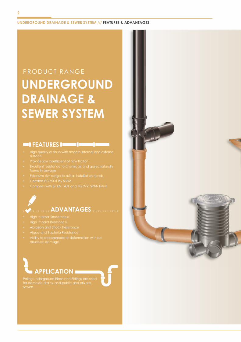
1. UnplasticizedPolyvinylChloride(PVC-U)Pipes for Non-Pressure Underground DrainageandSewerageapplication
PIPES
1. UnplasticizedPolyvinylChloride(PVC-U)Fittings for Non-Pressure Underground DrainageandSeweragesystem
QUALITY & CERTIFICATION
SYSTEM CERTIFICATION
UNDERGROUND DRAINAGE & SEWER SYSTEM /// ACCREDITATION
For updated copies of our certificates, please visit the Paling website www.paling.com.my
5
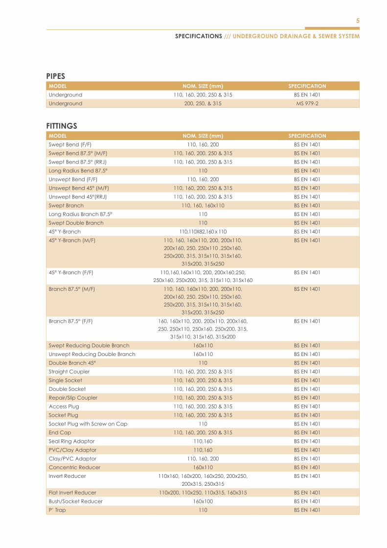
PIPESMODEL NOM. SIZE (mm) SPECIFICATION
Underground 110,160,200,250&315 BSEN1401
Underground 200,250,&315 MS979-2
FITTINGSMODEL NOM. SIZE (mm) SPECIFICATION
SweptBend(F/F) 110,160,200 BSEN1401
SweptBend87.5°(M/F) 110,160,200,250&315 BSEN1401
SweptBend87.5°(RRJ) 110,160,200,250&315 BSEN1401
LongRadiusBend87.5° 110 BSEN1401
UnsweptBend(F/F) 110,160,200 BSEN1401
UnsweptBend45°(M/F) 110,160,200,250&315 BSEN1401
UnsweptBend45°(RRJ) 110,160,200,250&315 BSEN1401
SweptBranch 110,160,160x110 BSEN1401
LongRadiusBranch87.5° 110 BSEN1401
SweptDoubleBranch 110 BSEN1401
45°Y-Branch 110,110X82,160x110 BSEN1401
45°Y-Branch(M/F) 110,160,160x110,200,200x110,
200x160,250,250x110,250x160,
250x200,315,315x110,315x160,
315x200,315x250
BSEN1401
45°Y-Branch(F/F) 110,160,160x110,200,200x160,250,
250x160,250x200,315,315x110,315x160
BSEN1401
Branch87.5°(M/F) 110,160,160x110,200,200x110,
200x160,250,250x110,250x160,
250x200,315,315x110,315x160,
315x200,315x250
BSEN1401
Branch87.5°(F/F) 160,160x110,200,200x110,200x160,
250,250x110,250x160,250x200,315,
315x110,315x160,315x200
BSEN1401
SweptReducingDoubleBranch 160x110 BSEN1401
UnsweptReducingDoubleBranch 160x110 BSEN1401
DoubleBranch45° 110 BSEN1401
Straight Coupler 110,160,200,250&315 BSEN1401
Single Socket 110,160,200,250&315 BSEN1401
Double Socket 110,160,200,250&315 BSEN1401
Repair/SlipCoupler 110,160,200,250&315 BSEN1401
Access Plug 110,160,200,250&315 BSEN1401
Socket Plug 110,160,200,250&315 BSEN1401
SocketPlugwithScrewonCap 110 BSEN1401
End Cap 110,160,200,250&315 BSEN1401
Seal Ring Adaptor 110,160 BSEN1401
PVC/ClayAdaptor 110,160 BSEN1401
Clay/PVCAdaptor 110,160,200 BSEN1401
Concentric Reducer 160x110 BSEN1401
Invert Reducer 110x160,160x200,160x250,200x250,
200x315,250x315
BSEN1401
Flat Invert Reducer 110x200,110x250,110x315,160x315 BSEN1401
Bush/SocketReducer 160x100 BSEN1401
P’ Trap 110 BSEN1401
SPECIFICATIONS /// UNDERGROUND DRAINAGE & SEWER SYSTEM
6
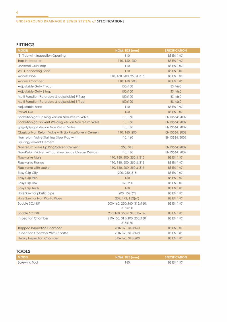
FITTINGSMODEL NOM. SIZE (mm) SPECIFICATION
‘S’TrapwithInspectionOpening 110 BSEN1401
Trap Interceptor 110,160,200 BSEN1401
Universal Gully Trap 110 BSEN1401
WC Connecting Bend 110 BSEN1401
Access Pipe 110,160,200,250&315 BSEN1401
Access Chamber 110,160,200 BSEN1401
Adjustable Gully P trap 150x100 BS4660
Adjustable Gully S trap 150x100 BS4660
Multi-Function(Rotatable&adjustable)PTrap 150x100 BS4660
Multi-Function(Rotatable&adjustable)STrap 150x100 BS4660
Adjustable Bend 110 BSEN1401
Swivel160 160 BSEN1401
Socket/SpigotLipRingVersionNon-ReturnValve 110,160 EN13564:2002
Socket/SpigotSolventWeldingversionNonreturnValve 110,160 EN13564:2002
Spigot/SpigotVersionNonReturnValve 110,160 EN13564:2002
ClassicalNonReturnValvewithLipRing/SolventCement 110,160,200 EN13564:2002
NonreturnValveStainlessSteelFlapwith
LipRing/SolventCement
110,160 EN13564:2002
NonreturnvalveLipRing/SolventCement 250,315 EN13564:2002
Non-ReturnValve(without Emergency Closure Device) 110,160 EN13564:2002
Flap-valve Male 110,160,200,250&315 BSEN1401
Flap-valve Flange 110,160,200,250&315 BSEN1401
Flapvalvewithsocket 110,160,200,250&315 BSEN1401
Easy Clip City 200,250,315 BSEN1401
Easy Clip Plus 160 BSEN1401
Easy Clip Link 160,200 BSEN1401
Easy Clip Tech 160 BSEN1401
HoleSawforplasticpipe 200,152(6”) BSEN1401
HoleSawforNonPlasticPipes 202,172,152(6”) BSEN1401
SaddleSCJ45° 200x160,250x160,315x160,
315x200
BSEN1401
SaddleSCJ90° 200x160,250x160,315x160 BSEN1401
Inspection Chamber 250x100,315x100,250x160,
315x160
BSEN1401
Trapped Inspection Chamber 250x160,315x160 BSEN1401
InspectionChamberWithC.baffle 250x160,315x160 BSEN1401
Heavy Inspection Chamber 315x160,315x200 BSEN1401
TOOLSMODEL NOM. SIZE (mm) SPECIFICATION
ScrewingTool 160 BSEN1401
UNDERGROUND DRAINAGE & SEWER SYSTEM /// SPECIFICATIONS
7
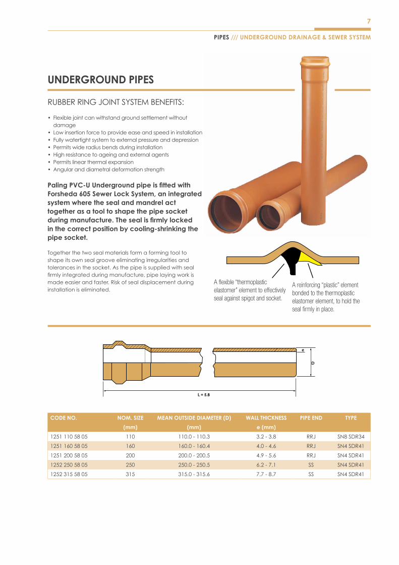
UNDERGROUND PIPES
RUBBERRINGJOINTSYSTEMBENEFITS:
• Flexiblejointcanwithstandgroundsettlementwithoutdamage
• Lowinsertionforcetoprovideeaseandspeedininstallation• Fullywatertightsystemtoexternalpressureanddepression• Permitswideradiusbendsduringinstallation• High resistance to ageing and external agents• Permits linear thermal expansion• Angular and diametral deformation strength
Paling PVC-U Underground pipe is fitted with Forsheda 605 Sewer Lock System, an integrated system where the seal and mandrel act together as a tool to shape the pipe socket during manufacture. The seal is firmly locked in the correct position by cooling-shrinking the pipe socket.
Togetherthetwosealmaterialsformaformingtooltoshapeitsownsealgrooveeliminatingirregularitiesandtolerancesinthesocket.Asthepipeissuppliedwithsealfirmlyintegratedduringmanufacture,pipelayingworkismade easier and faster. Risk of seal displacement during installation is eliminated.
CODE NO. NOM. SIZE MEAN OUTSIDE DIAMETER (D) WALL THICKNESS PIPE END TYPE
(mm) (mm) e (mm)
12511105805 110 110.0-110.3 3.2-3.8 RRJ SN8SDR34
12511605805 160 160.0-160.4 4.0-4.6 RRJ SN4SDR41
12512005805 200 200.0-200.5 4.9-5.6 RRJ SN4SDR41
12522505805 250 250.0-250.5 6.2-7.1 SS SN4SDR41
12523155805 315 315.0-315.6 7.7-8.7 SS SN4SDR41
PIPES /// UNDERGROUND DRAINAGE & SEWER SYSTEM
D
e
L = 5.8
8
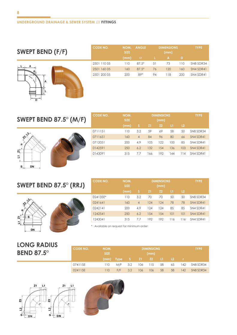
LONG RADIUS BEND 87.5°
CODE NO. NOM. SIZE
ANGLE DIMENSIONS(mm)
TYPE
(mm) Ѳ L A D
250111005 110 87.5° 51 73 110 SN8SDR34
250116005 160 87.5° 76 120 160 SN4SDR41
250120005 200 89° 94 118 200 SN4SDR41
SWEPT BEND (F/F)
SWEPT BEND 87.5° (M/F)
L
L
A
A
D
CODE NO. NOM. SIZE
DIMENSIONS(mm)
TYPE
(mm) S Z1 Z2 L1 L2
0711151 110 3.2 59 69 58 50 SN8SDR34
0711651 160 4 84 96 80 66 SN4SDR41
0712051 200 4.9 105 122 100 85 SN4SDR41
0142591 250 6.2 132 154 136 103 SN4SDR41
0143091 315 7.7 166 192 144 114 SN4SDR41
CODE NO. NOM. SIZE
DIMENSIONS(mm)
TYPE
(mm) S Z1 Z2 L1 L2
024135E* 110 3.2 70 70 50 50 SN8SDR34
0241641 160 4 124 124 78 78 SN4SDR41
0242141 200 4.9 124 124 85 85 SN4SDR41
1242541 250 6.2 154 154 101 101 SN4SDR41
1243041 315 7.7 192 192 116 116 SN4SDR41
* Availableonrequestforminimumorder
SWEPT BEND 87.5° (RRJ)
UNDERGROUND DRAINAGE & SEWER SYSTEM /// FITTINGS
CODE NO. NOM.SIZE
DIMENSIONS(mm)
TYPE
(mm) Type S Z1 Z2 L1 L2 r
074115E 110 M/F 3.2 106 115 58 65 142 SN8SDR34
024115E 110 F/F 3.2 106 106 58 58 142 SN8SDR34

9
L1
A
D
UNSWEPT BEND (F/F)
FITTINGS /// UNDERGROUND DRAINAGE & SEWER SYSTEM
CODE NO. NOM. SIZE
ANGLE DIMENSIONS(mm)
TYPE
(mm) Ѳ L1 A D
250711005 110 41° 50 20 110 SN8SDR34
251011005 110 45° 50 20 110 SN8SDR34
251016005 160 45° 76 30 160 SN4SDR41
251020005 200 45° 90 55 200 SN8SDR34
250511005 110 68° 52 56 110 SN4SDR41
250516005 160 68° 80 74 160 SN4SDR41
250520005 200 68° 100 96 200 SN4SDR41
UNSWEPT BEND 45° (M/F)CODE NO. NOM.
SIZEDIMENSIONS
(mm)TYPE
(mm) S Z1 Z2 L1 L2
0121151 110 3.2 27 36 58 50 SN8SDR34
0701651 160 4 37 51 80 66 SN4SDR41
0702051 200 4.9 46 64 100 84 SN4SDR41
0122591 250 6.2 58 79 125 96 SN4SDR41
0123091 315 7.7 73 100 144 118 SN4SDR41
UNSWEPT BEND 45° (RRJ)CODE NO. NOM.
SIZEDIMENSIONS
(mm)TYPE
(mm) S Z1 Z2 L1 L2
023115E* 110 3.2 37 37 50 50 SN8SDR34
0231641 160 4 49 49 73 73 SN4SDR41
0232041 200 4.9 65 65 85 85 SN4SDR41
1232541 250 6.2 79 79 101 101 SN4SDR41
1233041 315 7.7 100 100 116 116 SN4SDR41
* Availableonrequestforminimumorder
SWEPT BRANCH
L2 A
L
L1
D
CE
D1
CODE NO. NOM. SIZE
ANGLE DIMENSIONS(mm)
TYPE
(mm) Ѳ L L1 L2 A C E D D1
251111005 110 87.5° 250 50 50 75 - 56 110 110 SN8SDR34
251116005 160 87.5° 360 77 77 145 82 56 160 160 SN4SDR41
251116011005 160x110 87.5° 312 76 48 120 - 56 160 110 SN4SDR41
10
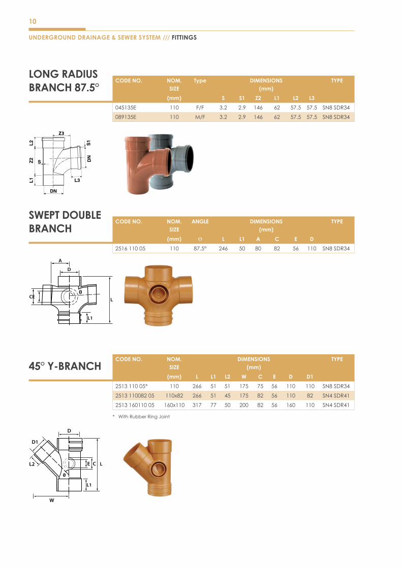
LONG RADIUS BRANCH 87.5°
CODE NO. NOM. SIZE
DIMENSIONS(mm)
TYPE
(mm) L L1 L2 W C E D D1
251311005* 110 266 51 51 175 75 56 110 110 SN8SDR34
251311008205 110x82 266 51 45 175 82 56 110 82 SN4SDR41
251316011005 160x110 317 77 50 200 82 56 160 110 SN4SDR41
* WithRubberRingJoint
CODE NO. NOM. SIZE
Type DIMENSIONS(mm)
TYPE
(mm) S S1 Z2 L1 L2 L3
045135E 110 F/F 3.2 2.9 146 62 57.5 57.5 SN8SDR34
089135E 110 M/F 3.2 2.9 146 62 57.5 57.5 SN8SDR34
CODE NO. NOM. SIZE
ANGLE DIMENSIONS(mm)
TYPE
(mm) Ѳ L L1 A C E D
251611005 110 87.5° 246 50 80 82 56 110 SN8SDR34
SWEPT DOUBLE BRANCH
D
L1
CE L
A
D
D1
L2 E C L
W
L1
Z3
45° Y-BRANCH
UNDERGROUND DRAINAGE & SEWER SYSTEM /// FITTINGS
11
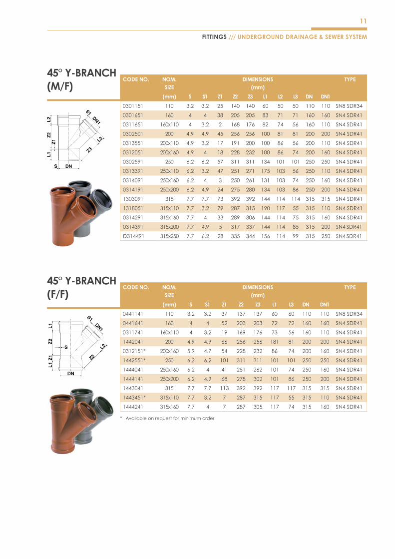
45° Y-BRANCH (M/F)
45° Y-BRANCH (F/F)
CODE NO. NOM. SIZE
DIMENSIONS(mm)
TYPE
(mm) S S1 Z1 Z2 Z3 L1 L2 L3 DN DN1
0301151 110 3.2 3.2 25 140 140 60 50 50 110 110 SN8SDR34
0301651 160 4 4 38 205 205 83 71 71 160 160 SN4SDR41
0311651 160x110 4 3.2 2 168 176 82 74 56 160 110 SN4SDR41
0302501 200 4.9 4.9 45 256 256 100 81 81 200 200 SN4SDR41
0313551 200x110 4.9 3.2 17 191 200 100 86 56 200 110 SN4SDR41
0312051 200x160 4.9 4 18 228 232 100 86 74 200 160 SN4SDR41
0302591 250 6.2 6.2 57 311 311 134 101 101 250 250 SN4SDR41
0313391 250x110 6.2 3.2 47 251 271 175 103 56 250 110 SN4SDR41
0314091 250x160 6.2 4 3 250 261 131 103 74 250 160 SN4SDR41
0314191 250x200 6.2 4.9 24 275 280 134 103 86 250 200 SN4SDR41
1303091 315 7.7 7.7 73 392 392 144 114 114 315 315 SN4SDR41
1318051 315x110 7.7 3.2 79 287 315 190 117 55 315 110 SN4SDR41
0314291 315x160 7.7 4 33 289 306 144 114 75 315 160 SN4SDR41
0314391 315x200 7.7 4.9 5 317 337 144 114 85 315 200 SN4 SDR41
D314491 315x250 7.7 6.2 28 335 344 156 114 99 315 250 SN4 SDR41
CODE NO. NOM. SIZE
DIMENSIONS(mm)
TYPE
(mm) S S1 Z1 Z2 Z3 L1 L3 DN DN1
0441141 110 3.2 3.2 37 137 137 60 60 110 110 SN8SDR34
0441641 160 4 4 52 203 203 72 72 160 160 SN4SDR41
0311741 160x110 4 3.2 19 169 176 73 56 160 110 SN4SDR41
1442041 200 4.9 4.9 66 256 256 181 81 200 200 SN4SDR41
0312151* 200x160 5.9 4.7 54 228 232 86 74 200 160 SN4SDR41
1442551* 250 6.2 6.2 101 311 311 101 101 250 250 SN4SDR41
1444041 250x160 6.2 4 41 251 262 101 74 250 160 SN4SDR41
1444141 250x200 6.2 4.9 68 278 302 101 86 250 200 SN4SDR41
1443041 315 7.7 7.7 113 392 392 117 117 315 315 SN4SDR41
1443451* 315x110 7.7 3.2 7 287 315 117 55 315 110 SN4SDR41
1444241 315x160 7.7 4 7 287 305 117 74 315 160 SN4SDR41
* Availableonrequestforminimumorder
FITTINGS /// UNDERGROUND DRAINAGE & SEWER SYSTEM

12
UNDERGROUND DRAINAGE & SEWER SYSTEM /// FITTINGS
BRANCH 87.5° (M/F)
BRANCH 87.5° (F/F)
CODE NO. NOM. SIZE
DIMENSIONS(mm)
TYPE
(mm) S S1 Z1 Z2 Z3 L1 L2 L3 DN DN1
0341151 110 3.2 3.2 55 69 69 60 50 50 110 110 SN8SDR34
0811651 160 4 4 76 98 98 88 74 74 160 160 SN4SDR41
035165E 160x110 4 3.2 59 69 87 81 74 57 160 110 SN4SDR41
081205E 200 4.9 4.9 105 119 119 100 86 86 200 200 SN4SDR41
035015E 200x110 4.9 3.2 50 110 120 135 86 59 200 110 SN4SDR41
0352051 200x160 4.9 4 75 110 132 110 86 74 200 160 SN4SDR41
0342591 250 6.2 6.2 120 152 152 135 101 101 250 250 SN4SDR41
0353551 250x110 6.2 3.2 90 100 132 144 99 51 250 110 SN4SDR41
0354051 250x160 6.2 4 90 100 134 117 126 85 250 160 SN4SDR41
0353851 250x200 6.2 4.9 132 143 136 123 120 116 250 200 SN4SDR41
1343091 315 7.7 7.7 166 185 174 146 114 114 315 315 SN4SDR41
1352251 315x110 7.7 3.2 50 150 176 180 116 56 315 110 SN4SDR41
1354451 315x160 7.7 4 75 150 180 155 116 73 315 160 SN4SDR41
1355551 315x200 7.7 4.9 95 150 185 135 116 87 315 200 SN4SDR41
D354691 315x250 7.7 6.2 166 178 174 128 140 110 315 250 SN4SDR41
CODE NO. NOM. SIZE
DIMENSIONS(mm)
TYPE
(mm) S S1 Z1 Z2 Z3 L1 L3 DN DN1
0451641 160 4 4 95 99 99 72 72 160 160 SN4SDR41
0351741 160x110 4 3.2 70 75 95 72 56 160 110 SN4SDR41
1452041 200 4.9 4.9 120 120 120 86 86 200 200 SN4SDR41
0460141 200x110 4.9 3.2 108 110 120 86 60 200 110 SN4SDR41
0460641 200x160 4.9 4 108 110 132 86 74 200 160 SN4SDR41
1452541 250 6.2 6.2 165 152 152 101 101 250 250 SN4SDR41
1461141 250x110 6.2 3.2 60 135 145 105 56 250 110 SN4SDR41
1461651* 250x160 6.2 4 100 100 134 107 126 250 160 SN4SDR41
1462051* 250x200 6.2 4.9 100 143 136 113 120 250 200 SN4SDR41
1453041 315 7.7 7.7 211 185 185 117 117 315 315 SN4SDR41
1464141 315x110 7.7 3.2 150 150 176 116 56 315 110 SN4SDR41
1464251 315x160 7.7 4 150 150 180 116 73 315 160 SN4SDR41
1464451 315x200 7.7 4.9 150 150 185 116 87 315 200 SN4SDR41
* Availableonrequestforminimumorder

13
FITTINGS /// UNDERGROUND DRAINAGE & SEWER SYSTEM
SWEPT REDUCING DOUBLE BRANCH
CODE NO. NOM. SIZE
ANGLE DIMENSIONS(mm)
TYPE
(mm) Ѳ L L1 L2 W B C E D D1
251116011005 160x110 87.5° 320 77 50 254 115 82 56 160 110 SN4SDR41
D L2
D1
B
CEL1
W
L
UNSWEPT REDUCING DOUBLE BRANCH
CODE NO. NOM. SIZE
ANGLE DIMENSIONS(mm)
TYPE
(mm) Ѳ L L1 L2 W B C E D D1
251816011005 160x110 45° 320 71 50 195 153 82 56 160 110 SN4SDR41
D
D1
L2
L1C E
B
W
L
DOUBLE BRANCH 45°
STRAIGHT COUPLERCODE NO. NOM.
SIZEDIMENSIONS
(mm)TYPE
(mm) L L1 A D
252511005 110 110 53 4 110 SN8SDR34
252516005 160 167 82 4 160 SN4SDR41
252520005 200 184 90 4 200 SN4SDR41
252525005 250 225 110 5 250 SN4SDR41
252531505∆ 315 297 144 9 315 SN4SDR41
∆ Fabricationitem
L1
L1
A
D
L
D
CODE NO. NOM. SIZE
DIMENSIONS(mm)
TYPE
(mm) S Z1 Z2 L L1
0361141 110 3.2 30 141 57 60 SN8SDR34

14
SINGLE SOCKET CODE NO. NOM.
SIZEDIMENSIONS
(mm)TYPE
(mm) S L1 L2
0631181 110 2.9 60 122 SN4SDR41
0631681 160 3.6 75 154 SN4SDR41
0632081 200 4.4 106 217 SN4SDR41
0632581 250 5.5 123 254 SN4SDR41
0633081 315 6.9 144 297 SN4SDR41
DOUBLE SOCKET
ACCESS PLUG
REPAIR/SLIP COUPLER
UNDERGROUND DRAINAGE & SEWER SYSTEM /// FITTINGS
CODE NO. NOM. SIZE
DIMENSIONS(mm)
TYPE
(mm) L L1 D D1
250651101 110 62 19 110 125 SN8SDR34
251651601 160 60 23 160 176 SN4SDR41
251652001 200 80 23 200 216 SN4SDR41
251652501 250 90 18 250 262 SN4SDR41
251653001 315 93 22 315 354 SN4SDR41
CODE NO. NOM. SIZE
DIMENSIONS(mm)
TYPE
(mm) S L1 L2
0631151 110 2.9 60 122 SN4SDR41
063165E 160 3.6 75 151 SN4SDR41
063205E 200 4.4 106 217 SN4SDR41
0632591 250 5.5 123 254 SN4SDR41
0633091 315 6.9 144 297 SN4SDR41
CODE NO. NOM. SIZE
DIMENSIONS(mm)
TYPE
(mm) S L1
250611151 110 2.9 122 SN4SDR41
250611651 160 3.6 151 SN4SDR41
250612051 200 4.4 217 SN4SDR41
250612591 250 5.5 254 SN4SDR41
250613091 315 6.9 297 SN4SDR41
D1
L1
L
D
160 to 200mm 250 to 315mm
110mm

15
CODE NO. NOM. SIZE
DIMENSIONS(mm)
TYPE
(mm) L L1 D1 D
252911008205 110 77 50 110 76 SN8SDR34
CODE NO. NOM. SIZE
DIMENSIONS(mm)
TYPE
(mm) L D D1
250661101 110 38 110 126 SN8SDR34
250661601 160 49 160 180 SN4SDR41
250662001 200 59 200 223 SN4SDR41
250662501 250 90 250 282 SN4SDR41
250663001 315 93 315 350 SN4SDR41
SEAL RING ADAPTOR
SOCKET PLUG
SOCKET PLUGwith Screw on Cap
END CAP
FITTINGS /// UNDERGROUND DRAINAGE & SEWER SYSTEM
CODE NO. NOM. SIZE
DIMENSIONS(mm)
TYPE
(mm) L A D
254208205 110 38 7 110 SN8SDR34
254211005 160 42 9 160 SN4SDR41
CODE NO. NOM. SIZE
DIMENSIONS(mm)
TYPE
(mm) S L1
06613F1 110 2 32 SN4SDR41
06617F1 160 2.7 35 SN4SDR41
06621F1 200 2.9 35 SN4SDR41
06628F1 250 3.5 40 SN4SDR41
06634F1 315 4 52 SN4SDR41
D
D1
L
D
AL
D1
D
L1
L
16
UNDERGROUND DRAINAGE & SEWER SYSTEM /// FITTINGS
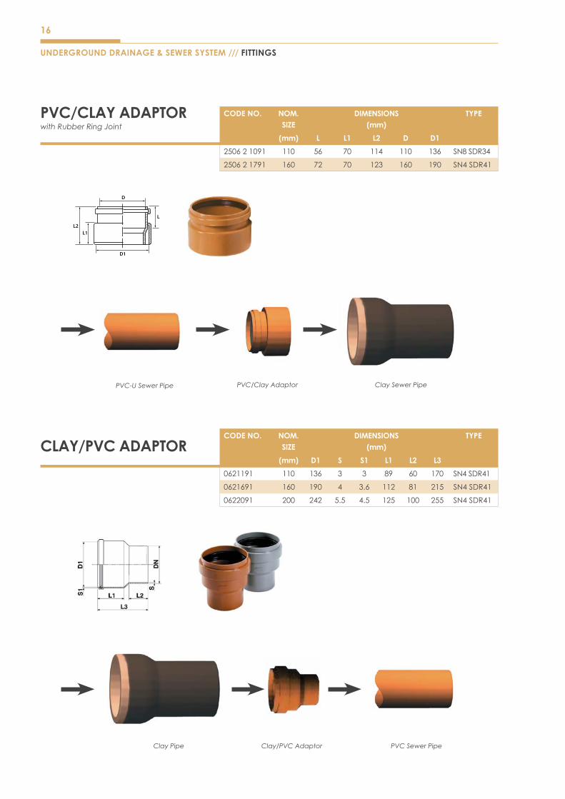
PVC/CLAY ADAPTOR with Rubber Ring Joint
CODE NO. NOM. SIZE
DIMENSIONS(mm)
TYPE
(mm) L L1 L2 D D1
250621091 110 56 70 114 110 136 SN8SDR34
250621791 160 72 70 123 160 190 SN4SDR41
CLAY/PVC ADAPTORCODE NO. NOM.
SIZEDIMENSIONS
(mm)TYPE
(mm) D1 S S1 L1 L2 L3
0621191 110 136 3 3 89 60 170 SN4SDR41
0621691 160 190 4 3.6 112 81 215 SN4SDR41
0622091 200 242 5.5 4.5 125 100 255 SN4SDR41
PVC Sewer PipeClay/PVC AdaptorClay Pipe
D
L
D1
L2L1
Clay Sewer PipePVC/Clay AdaptorPVC-U Sewer Pipe
17
D
D1
L1
L
L2
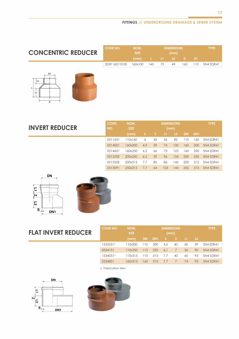
CONCENTRIC REDUCER
INVERT REDUCER
FLAT INVERT REDUCER
FITTINGS /// UNDERGROUND DRAINAGE & SEWER SYSTEM
CODE NO. NOM. SIZE
DIMENSIONS(mm)
TYPE
(mm) L L1 L2 D D1
253916011005 160x100 145 75 49 160 110 SN4SDR41
CODE NO.
NOM. SIZE
DIMENSIONS(mm)
TYPE
(mm) S Z L1 L2 DN DN1
0511651 110x160 4 43 56 82 110 160 SN4SDR41
0514051 160x200 4.9 39 74 100 160 200 SN4SDR41
0514651 160x250 6.2 66 73 125 160 250 SN4SDR41
051255E 200x250 6.2 39 96 134 200 250 SN4SDR41
051335E 200x315 7.7 85 86 145 200 315 SN4SDR41
0513091 250x315 7.7 64 103 144 250 315 SN4SDR41
CODE NO. NOM. SIZE
DIMENSIONS(mm)
TYPE
(mm) DN DN1 S Z L1 L2
1533551∆ 110x200 110 200 4.6 40 60 59 SN4SDR41
0534151 110x250 110 250 6.1 7 56 90 SN4SDR41
1534051∆ 110x315 110 315 7.7 40 60 93 SN4SDR41
0534851 160x315 160 315 7.7 7 74 93 SN4SDR41
∆ Fabricationitem
18
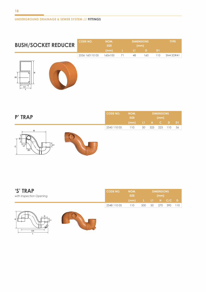
P’ TRAP
‘S’ TRAPwith Inspection Opening
UNDERGROUND DRAINAGE & SEWER SYSTEM /// FITTINGS
C L1
D1
D
A
L1
CODE NO. NOM. SIZE
DIMENSIONS(mm)
(mm) L1 A C D D1
254511005 110 50 325 223 110 56
CODE NO. NOM. SIZE
DIMENSIONS(mm)
(mm) L L1 H C/C D
254811005 110 500 50 270 390 110
C/C
L
D
H L1
BUSH/SOCKET REDUCER
D
LL1
D1
CODE NO. NOM. SIZE
DIMENSIONS(mm)
TYPE
(mm) L L1 D D1
253616011005 160x100 71 48 160 110 SN4SDR41
19
FITTINGS /// UNDERGROUND DRAINAGE & SEWER SYSTEM
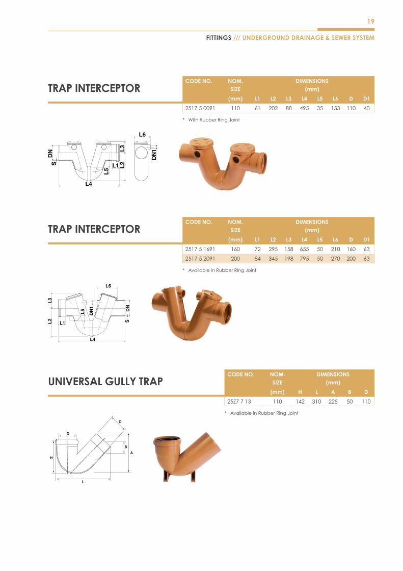
TRAP INTERCEPTORCODE NO. NOM.
SIZEDIMENSIONS
(mm)
(mm) L1 L2 L3 L4 L5 L6 D D1
251750091 110 61 202 88 495 35 153 110 40
* WithRubberRingJoint
TRAP INTERCEPTORCODE NO. NOM.
SIZEDIMENSIONS
(mm)
(mm) L1 L2 L3 L4 L5 L6 D D1
251751691 160 72 295 158 655 50 210 160 63
251752091 200 84 345 198 795 50 270 200 63
* AvailableinRubberRingJoint
UNIVERSAL GULLY TRAPCODE NO. NOM.
SIZEDIMENSIONS
(mm)
(mm) H L A B D
25Z7713 110 142 310 225 50 110
* AvailableinRubberRingJoint
20
UNDERGROUND DRAINAGE & SEWER SYSTEM /// FITTINGS
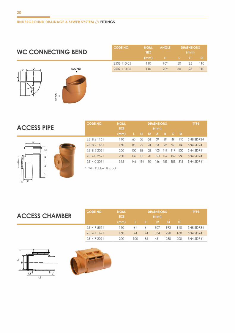
ACCESS PIPECODE NO. NOM.
SIZEDIMENSIONS
(mm)TYPE
(mm) L L1 L2 A B C D
251821151 110 60 55 36 59 69 69 110 SN8SDR34
251821651 160 85 72 24 83 99 99 160 SN4SDR41
251822051 200 100 86 28 105 119 119 200 SN4SDR41
251402591 250 135 101 70 120 152 152 250 SN4SDR41
251403091 315 146 114 90 166 185 185 315 SN4SDR41
* WithRubberRingJoint
L2 C
D
L
A
B
L1
D
ACCESS CHAMBERCODE NO. NOM.
SIZEDIMENSIONS
(mm)TYPE
(mm) L L1 L2 L3 D
251475551 110 61 61 307 192 110 SN8SDR34
251471691 160 74 74 334 220 160 SN4SDR41
251472091 200 100 86 451 280 200 SN4SDR41
L3D
L1 LL2
WC CONNECTING BENDCODE NO. NOM.
SIZEANGLE DIMENSIONS
(mm)
(mm) Ѳ L L1 D
250811005 110 90° 50 25 110
250911005 110 90° 50 25 110
L
L1D
SP
IGO
T
SOCKET

21
FITTINGS /// UNDERGROUND DRAINAGE & SEWER SYSTEM
ADJUSTABLE GULLY P TRAP
ADJUSTABLE GULLY S TRAP
MULTI-FUNCTION (ROTATABLE & ADJUSTABLE) P TRAP
MULTI-FUNCTION (ROTATABLE & ADJUSTABLE) S TRAP
CODE NO. NOM. SIZE
DIMENSIONS(mm)
TYPE
(mm) C1 L1 H1 S1
AGPT150100 150x100 262 369 52 230 SN4SDR41
CODE NO. NOM. SIZE
DIMENSIONS(mm)
TYPE
(mm) C1 L1 L2
AGST150100 150x100 270 369 285 SN4SDR41
CODE NO. NOM. SIZE
DIMENSIONS(mm)
ANGLE TYPE
(mm) H1 C1 L1 L2 a
SMFPT150100 150x100 52 260 363 239 2 SN4SDR41
CODE NO. NOM. SIZE
DIMENSIONS(mm)
ANGLE TYPE
(mm) H1 C1 L1 L2 a
SMFST150100 150x100 52 378 363 308 2 SN4SDR41

22
UNDERGROUND DRAINAGE & SEWER SYSTEM /// FEATURES & ADVANTAGES
ADJUSTABLE BEND AND SWIVEL
ADJUSTABLE BEND CODE NO. NOM. SIZE ANGLE DIMENSIONS (mm)
DN (mm) α S Z1 Z2 L1 L2
25H999941 110 5°–30° 3.2 26 36 62 59
CODE NO. NOM. SIZE ANGLE DIMENSIONS (mm)
DN (mm) α L L1 DN
1991658 160 +/-10° 180 85 160
SWIVEL 160
• Adjustable bend & Swivel provide flexibility during installation on uneven ground settlement.
ADVANTAGES
23
FEATURES & ADVANTAGES /// UNDERGROUND DRAINAGE & SEWER SYSTEM
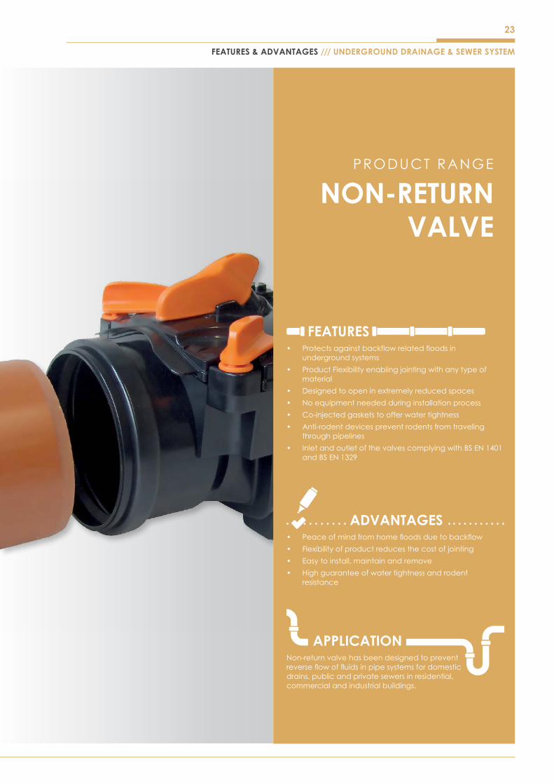
FEATURES• Protectsagainstbackflowrelatedfloodsin
underground systems
• ProductFlexibilityenablingjointingwithanytypeofmaterial
• Designed to open in extremely reduced spaces
• No equipment needed during installation process
• Co-injectedgasketstoofferwatertightness
• Anti-rodent devices prevent rodents from traveling through pipelines
• InletandoutletofthevalvescomplyingwithBSEN1401andBSEN1329
ADVANTAGES• Peaceofmindfromhomefloodsduetobackflow
• Flexibility of product reduces the cost of jointing
• Easy to install, maintain and remove
• Highguaranteeofwatertightnessandrodentresistance
APPLICATIONNon-return valve has been designed to prevent reverseflowoffluidsinpipesystemsfordomesticdrains,publicandprivatesewersinresidential,commercial and industrial buildings.
NON-RETURN VALVE
PRODUCT RANGE

24
UNDERGROUND DRAINAGE & SEWER SYSTEM /// NON RETURN VALVE
SOCKET/SPIGOT LIP RING VERSION
TYPE 2 SINGLE SOCKET-RRJ-ALL PLASTIC SMOOTH MATERIALS ØOD
CODE NO. NOM. SIZE
DIMENSIONS(mm)
DN (mm) S L L1 L2 L3 L4 OFFSET
12R1148 110 3.2 171 65 63 350 184 7
12R1648 160 4 255 83 82 491 226 9
TYPE 1 SINGLE SOCKET-RRJ-ALL PLASTIC SMOOTH MATERIALS ØOD
CODE NO. NOM. SIZE
DIMENSIONS(mm)
DN (mm) S L L1 L2 L3 L4 OFFSET
11R1148 110 3.2 171 65 63 350 184 7
11R1648 160 4 255 83 82 491 226 9
Lip Seal Version, we recommend to lubricate the
gasket to make installation easier.
25
NON RETURN VALVE /// UNDERGROUND DRAINAGE & SEWER SYSTEM
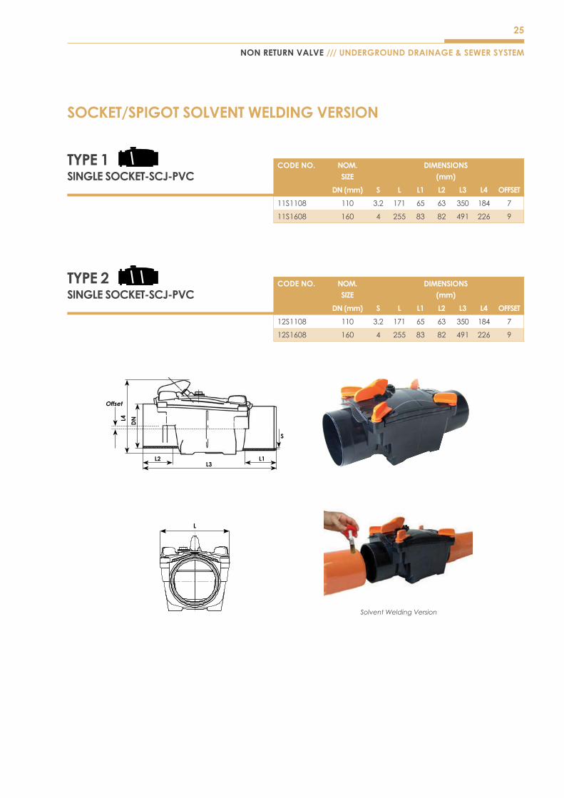
SOCKET/SPIGOT SOLVENT WELDING VERSION
CODE NO. NOM. SIZE
DIMENSIONS(mm)
DN (mm) S L L1 L2 L3 L4 OFFSET
12S1108 110 3.2 171 65 63 350 184 7
12S1608 160 4 255 83 82 491 226 9
TYPE 2SINGLE SOCKET-SCJ-PVC
TYPE 1SINGLE SOCKET-SCJ-PVC
CODE NO. NOM. SIZE
DIMENSIONS(mm)
DN (mm) S L L1 L2 L3 L4 OFFSET
11S1108 110 3.2 171 65 63 350 184 7
11S1608 160 4 255 83 82 491 226 9
Solvent Welding Version
26
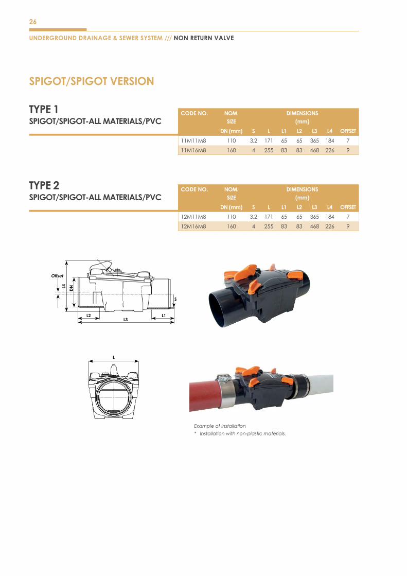
UNDERGROUND DRAINAGE & SEWER SYSTEM /// NON RETURN VALVE
SPIGOT/SPIGOT VERSION
TYPE 2SPIGOT/SPIGOT-ALL MATERIALS/PVC
CODE NO. NOM. SIZE
DIMENSIONS(mm)
DN (mm) S L L1 L2 L3 L4 OFFSET
12M11M8 110 3.2 171 65 65 365 184 7
12M16M8 160 4 255 83 83 468 226 9
TYPE 1SPIGOT/SPIGOT-ALL MATERIALS/PVC
CODE NO. NOM. SIZE
DIMENSIONS(mm)
DN (mm) S L L1 L2 L3 L4 OFFSET
11M11M8 110 3.2 171 65 65 365 184 7
11M16M8 160 4 255 83 83 468 226 9
Example of installation
* Installation with non-plastic materials.
27
NON RETURN VALVE /// UNDERGROUND DRAINAGE & SEWER SYSTEM
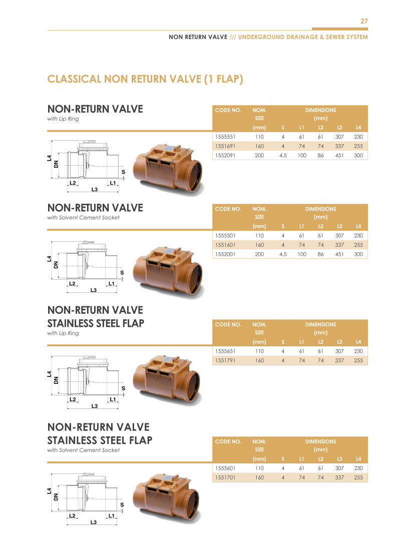
CLASSICAL NON RETURN VALVE (1 FLAP)
NON-RETURN VALVE with Lip Ring
CODE NO. NOM. SIZE
DIMENSIONS(mm)
(mm) S L1 L2 L3 L4
1555551 110 4 61 61 307 230
1551691 160 4 74 74 337 255
1552091 200 4.5 100 86 451 300
NON-RETURN VALVE STAINLESS STEEL FLAP with Lip Ring
CODE NO. NOM. SIZE
DIMENSIONS(mm)
(mm) S L1 L2 L3 L4
1555651 110 4 61 61 307 230
1551791 160 4 74 74 337 255
NON-RETURN VALVE STAINLESS STEEL FLAP with Solvent Cement Socket
CODE NO. NOM. SIZE
DIMENSIONS(mm)
(mm) S L1 L2 L3 L4
1555601 110 4 61 61 307 230
1551701 160 4 74 74 337 255
NON-RETURN VALVE with Solvent Cement Socket
CODE NO. NOM. SIZE
DIMENSIONS(mm)
(mm) S L1 L2 L3 L4
1555501 110 4 61 61 307 230
1551601 160 4 74 74 337 255
1552001 200 4.5 100 86 451 300

28
UNDERGROUND DRAINAGE & SEWER SYSTEM /// NON RETURN VALVE
NON-RETURN VALVE with Lip Ring
CODE NO. NOM. SIZE
DIMENSIONS(mm)
(mm) S L1 L2 L3 L4
1552591 250 6.2 130 102 520 374
1553091 315 7.7 160 125 615 440
NON-RETURN VALVE with Solvent Cement
CODE NO. NOM. SIZE
DIMENSIONS(mm)
(mm) S L1 L2 L3 L4
1552501 250 6.2 130 102 520 374
1553001 315 7.7 160 125 615 440
TYPE 0-NON-RETURN VALVE without Emergency Closure Device
CODE NO. NOM. SIZE
DIMENSIONS(mm)
(mm) L3 L4 DN1 S
NC879E1 110 280 170 154 20
NC919E1 160 396 257 236 25
29
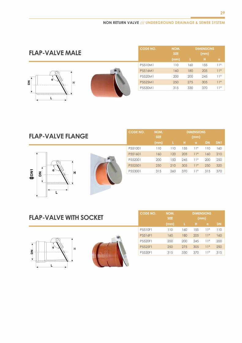
NON RETURN VALVE /// UNDERGROUND DRAINAGE & SEWER SYSTEM
FLAP-VALVE MALECODE NO. NOM.
SIZEDIMENSIONS
(mm)
(mm) L H α
P5510M1 110 160 155 11°
P5516M1 160 180 205 11°
P5520M1 200 200 245 11°
P5525M1 250 275 305 11°
P5530M1 315 330 370 11°
FLAP-VALVE FLANGECODE NO. NOM.
SIZEDIMENSIONS
(mm)
(mm) L H α DN DN1
P551001 110 110 155 11° 110 160
P551601 160 120 205 11° 160 210
P552001 200 150 245 11° 200 250
P552501 250 210 305 11° 250 320
P553001 315 260 370 11° 315 370
DN
1
FLAP-VALVE WITH SOCKETCODE NO. NOM.
SIZEDIMENSIONS
(mm)
(mm) L H α DN
P5510F1 110 160 155 11° 110
P5516F1 160 180 205 11° 160
P5520F1 200 200 245 11° 200
P5525F1 250 275 305 11° 250
P5530F1 315 330 370 11° 315

30
FEATURES• Greatly reduces time required for excavating and
backfilling existing pipelines
• ProductFlexibilityenablingjointingwithdifferenttypeofmaterial and size
• Increasesspeedofinstallationwithlowcost
• Eliminates the use of any sealants
• Guarantees joint security
• Prevents any potential accidents during excavating and backfilling
ADVANTAGES• Ease of overall installation process
• Flexibility of product reduces the cost of jointing
• Lowoverallinstallationcost
• Guarantees joint security
APPLICATIONSpecial mechanical connections are products that provides connection to different material and size of pipeline for underground domestic drains,publicandprivatesewerinresidential, commercial and industrial buildings.
SPECIAL MECHANICAL CONNECTIONS‘EASY CLIP’
PRODUCT RANGE
UNDERGROUND DRAINAGE & SEWER SYSTEM /// FEATURES & ADVANTAGES
31
FEATURES & ADVANTAGES /// UNDERGROUND DRAINAGE & SEWER SYSTEM
32
UNDERGROUND DRAINAGE & SEWER SYSTEM /// SPECIAL MECHANICAL CONNECTION
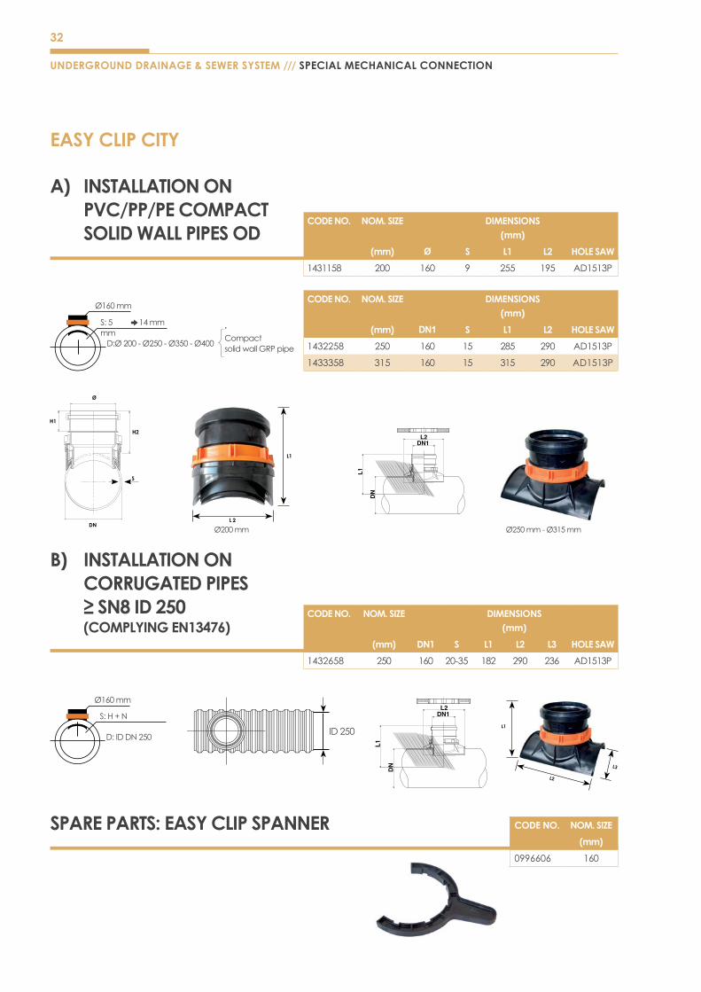
EASY CLIP CITY
A) INSTALLATION ON PVC/PP/PE COMPACT SOLID WALL PIPES OD
CODE NO. NOM. SIZE DIMENSIONS(mm)
(mm) Ø S L1 L2 HOLE SAW
1431158 200 160 9 255 195 AD1513P
CODE NO. NOM. SIZE DIMENSIONS(mm)
(mm) DN1 S L1 L2 HOLE SAW
1432258 250 160 15 285 290 AD1513P
1433358 315 160 15 315 290 AD1513P
Ø160mm
14mmS:5mmD:Ø200-Ø250-Ø350-Ø400
Compact solidwallGRPpipe
B) INSTALLATION ON CORRUGATED PIPES ≥ SN8 ID 250 (COMPLYING EN13476)
CODE NO. NOM. SIZE DIMENSIONS(mm)
(mm) DN1 S L1 L2 L3 HOLE SAW
1432658 250 160 20-35 182 290 236 AD1513P
ID250
Ø160mm
S:H+N
D:IDDN250
SPARE PARTS: EASY CLIP SPANNER CODE NO. NOM. SIZE
(mm)
0996606 160
L3
L2
L1
Ø200mm Ø250mm-Ø315mm
33
L3
L2
L1
SPECIAL MECHANICAL CONNECTION /// UNDERGROUND DRAINAGE & SEWER SYSTEM
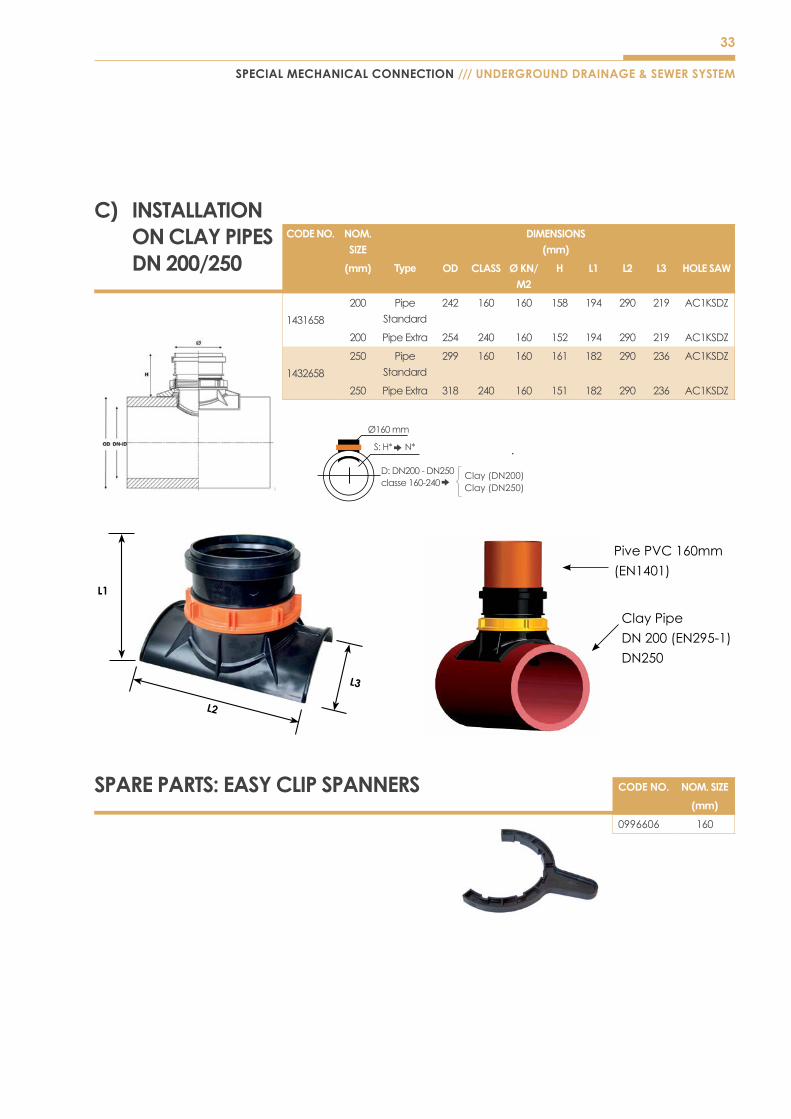
CODE NO. NOM. SIZE
DIMENSIONS(mm)
(mm) Type OD CLASS Ø KN/M2
H L1 L2 L3 HOLE SAW
1431658
200 Pipe
Standard
242 160 160 158 194 290 219 AC1KSDZ
200 Pipe Extra 254 240 160 152 194 290 219 AC1KSDZ
1432658
250 Pipe
Standard
299 160 160 161 182 290 236 AC1KSDZ
250 Pipe Extra 318 240 160 151 182 290 236 AC1KSDZ
PivePVC160mm
(EN1401)
Clay Pipe
DN200(EN295-1)
DN250
Ø160mm
N*S:H*
D:DN200-DN250classe160-240 Clay(DN250)
Clay(DN200)
C) INSTALLATION ON CLAY PIPES DN 200/250
SPARE PARTS: EASY CLIP SPANNERS CODE NO. NOM. SIZE
(mm)
0996606 160
34
DN
DN
H2
H2
H1
H1
S
S
UNDERGROUND DRAINAGE & SEWER SYSTEM /// SPECIAL MECHANICAL CONNECTION
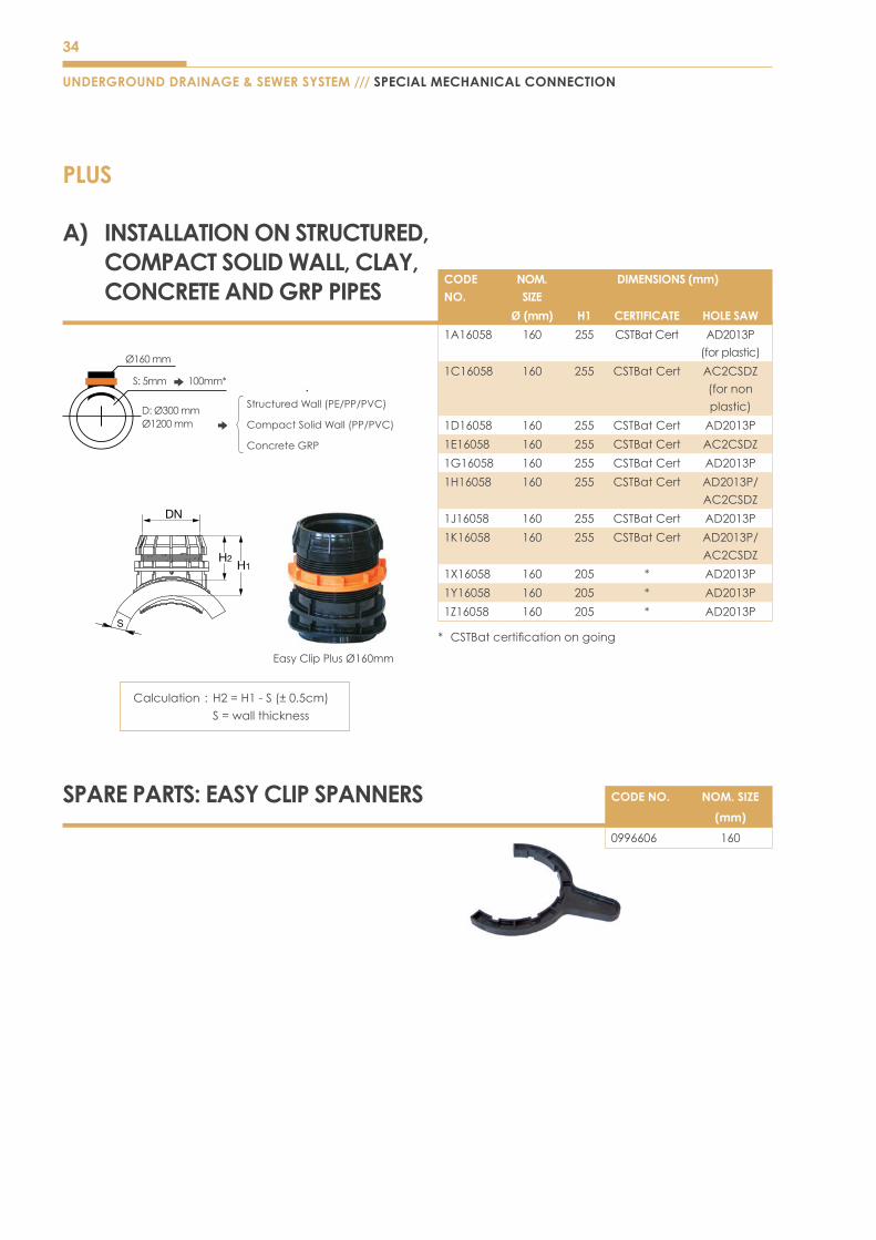
PLUS
A) INSTALLATION ON STRUCTURED, COMPACT SOLID WALL, CLAY, CONCRETE AND GRP PIPES
CODE NO.
NOM. SIZE
DIMENSIONS (mm)
Ø (mm) H1 CERTIFICATE HOLE SAW
1A16058 160 255 CSTBat Cert AD2013P
(forplastic)
1C16058 160 255 CSTBat Cert AC2CSDZ
(fornon
plastic)
1D16058 160 255 CSTBat Cert AD2013P
1E16058 160 255 CSTBat Cert AC2CSDZ
1G16058 160 255 CSTBat Cert AD2013P
1H16058 160 255 CSTBat Cert AD2013P/
AC2CSDZ
1J16058 160 255 CSTBat Cert AD2013P
1K16058 160 255 CSTBat Cert AD2013P/
AC2CSDZ
1X16058 160 205 * AD2013P
1Y16058 160 205 * AD2013P
1Z16058 160 205 * AD2013P
* CSTBatcertificationongoing
EasyClipPlusØ160mm
Ø160mm
100mm*S:5mm
D:Ø300mmØ1200mm CompactSolidWall(PP/PVC)
Concrete GRP
StructuredWall(PE/PP/PVC)
SPARE PARTS: EASY CLIP SPANNERS CODE NO. NOM. SIZE
(mm)
0996606 160
Calculation : H2=H1-S(±0.5cm)
S=wallthickness

35
LINK
SPECIAL MECHANICAL CONNECTION /// UNDERGROUND DRAINAGE & SEWER SYSTEM
SPARE PARTS: EASY CLIP SPANNERS CODE NO. NOM. SIZE
(mm)
0995508 160
0996008 200
A) INSTALLATION ON STRUCTURED, COMPACT SOLID WALL, CLAY, CONCRETE AND GRP PIPES
CODE NO.
NOM. SIZE
DIMENSIONS (mm)
Ø (mm) H1 REFERENCE CERTIFICATE
1A16L58 160 255 * AD2013P
(forplastic)
1C16L58 160 255 * AC2CSDZ
(fornon
plastic)
1D16L58 160 255 * AD2013P
1E16L58 160 255 * AC2CSDZ
1G16L58 160 255 * AD2013P
1H16L58 160 255 * AD2013P/
AC2CSDZ
1J16058 160 255 * AD2013P
1K16L58 160 255 * AD2013P/
AC2CSDZ
1X16L58 160 205 * AD2013P
1Y16L58 160 205 * AD2013P
1Z16L58 160 205 * AD2013P
1A20058 200 315 * AD2013P
(forplastic)
1C20058 200 315 * AC2CSDZ
(fornon
plastic)
1D20058 200 315 CSTBat Cert AD2013P
1E20058 200 315 CSTBat Cert AC2CSDZ
1G20058 200 315 CSTBat Cert AD2013P
1H20058 200 315 CSTBat Cert AD2013P/
AC2CSDZ
1J20058 200 315 CSTBat Cert AD2013P
1K20058 200 315 CSTBat Cert AD2013P/
AC2CSDZ
1X20058 200 265 * AD2013P
1Y20058 200 265 * AD2013P
1Z20058 200 265 * AD2013P
* CSTBatcertificationongoing
DN
H2H1
S
EasyclipØ160mm EasyclipØ200mm
DN
DN
H2
H2
H1
H1
S
S
Ø160-Ø200mm
100mm*S:5mm
D:Ø300mmØ1200mm
CompactSolidWall(PP/PVC)Clay
Concrete GRP
Structuredwall(wall(PE/PP/PVC)
Calculation : H2=H1-S(±0.5cm)
S=wallthickness
36
UNDERGROUND DRAINAGE & SEWER SYSTEM /// SPECIAL MECHANICAL CONNECTION
TECH
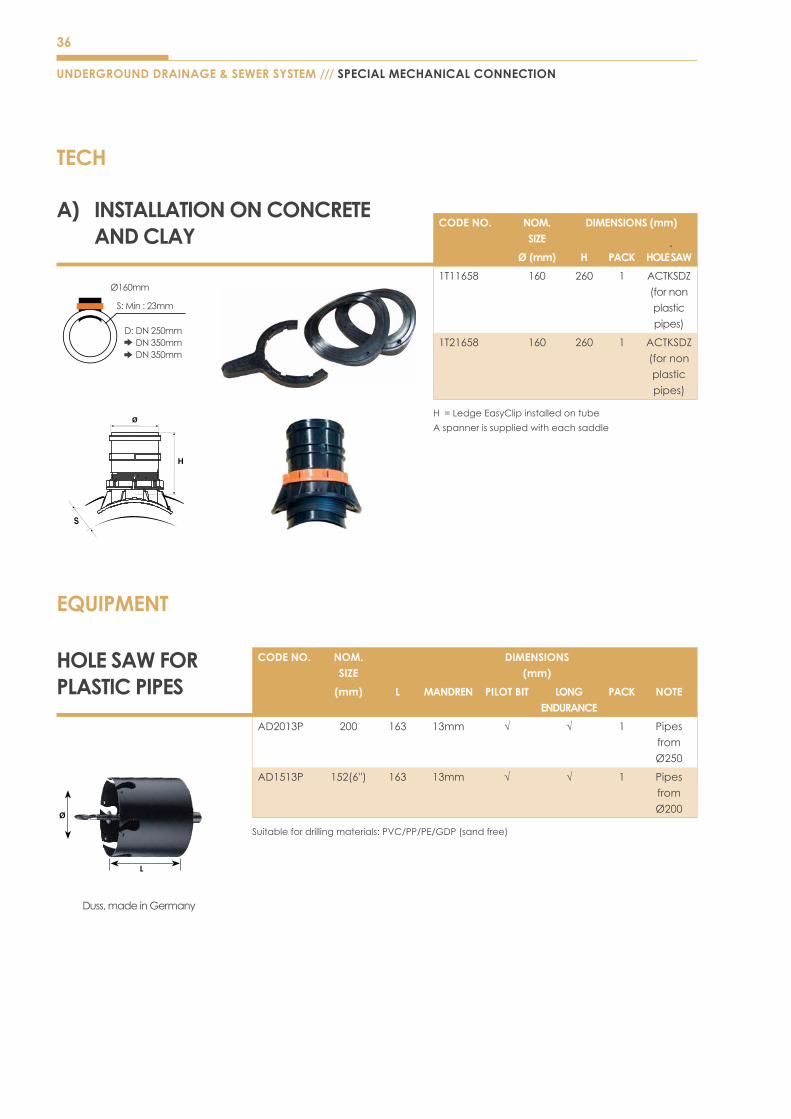
EQUIPMENT
HOLE SAW FOR PLASTIC PIPES
CODE NO. NOM. SIZE
DIMENSIONS (mm)
(mm) L MANDREN PILOT BIT LONG ENDURANCE
PACK NOTE
AD2013P 200 163 13mm √ √ 1 Pipes
from
Ø250
AD1513P 152(6'') 163 13mm √ √ 1 Pipes
from
Ø200
Suitablefordrillingmaterials:PVC/PP/PE/GDP(sandfree)
Ø
Duss, made in Germany
CODE NO. NOM. SIZE
DIMENSIONS (mm)
Ø (mm) H PACK HOLE SAW
1T11658 160 260 1 ACTKSDZ
(fornon
plastic
pipes)
1T21658 160 260 1 ACTKSDZ
(fornon
plastic
pipes)
H =LedgeEasyClipinstalledontube
Aspannerissuppliedwitheachsaddle
Ø160mm
S:Min:23mm
D:DN250mm DN350mm DN350mm
A) INSTALLATION ON CONCRETE AND CLAY

37
SPECIAL MECHANICAL CONNECTION /// UNDERGROUND DRAINAGE & SEWER SYSTEM
SADDLE SCJ 45°CODE NO. NOM.
SIZEDIMENSIONS
(mm)
(mm) DN DN1 α S S1 Z L1 L2 L3
0438491 200x160 200 160 45° 4.1 3.6 165 73 85 390
0438891 250x160 250 160 45° 5.5 3.6 165 73 92 400
0439491 315x160 315 160 45° 6.9 3.6 165 73 110 432
1433291 315x200 315 200 45° 6.0 4.4 236 95 86 513
SADDLE SCJ 90°CODE NO.
NOM. SIZE
DIMENSIONS (mm)
(mm) DN DN1 α S S1 Z L1 L2 L3
0434351 200x160 200 160 90° 4.4 3.6 34 58.5 77 322
1424251 250x160 250 160 90° 4.4 3.6 34 58.5 77 322
142525E 315x160 315 160 90° 4.4 3.6 34 58.5 77 322
HOLE SAW FOR NON PLASTIC PIPES
CODE NO.
NOM. SIZE
DIMENSIONS (mm)
(mm) L MANDREN PILOT BIT LONG ENDURANCE
PACK NOTE
AC2CSDZ 202 300 SDS max √ √ 1 Pipes
from
Ø250
ACTKSDZ 172 300 SDS max √ √ 1
AC1KSDZ 152(6'') 300 SDS max √ √ 1
Suitablefordrillingmaterials:Reinforcedconcrete/Reinforcedcorrugatedsteel/Fiberglassfilled
withsand/Clay
Ø
Duss, made in Germany
38
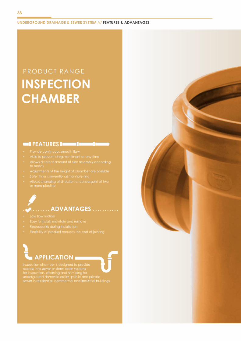
FEATURES• Providecontinuoussmoothflow
• Able to prevent dregs sentiment at any time
• Allowsdifferentamountofriserassemblyaccording to needs
• Adjustments of the height of chamber are possible
• Safer than conventional manhole ring
• Allowschangingofdirectionorconvergentoftwo or more pipeline
ADVANTAGES• Lowflowfriction
• Easy to install, maintain and remove
• Reduces risk during installation
• Flexibility of product reduces the cost of jointing
APPLICATIONInspection chamber is designed to provide accessintosewerorstormdrainsystemsfor inspection, cleaning and sampling for underground domestic drains, public and private sewerinresidential,commercialandindustrialbuildings
INSPECTION CHAMBER
PRODUCT RANGE
UNDERGROUND DRAINAGE & SEWER SYSTEM /// FEATURES & ADVANTAGES
39
FEATURES & ADVANTAGES /// UNDERGROUND DRAINAGE & SEWER SYSTEM
40
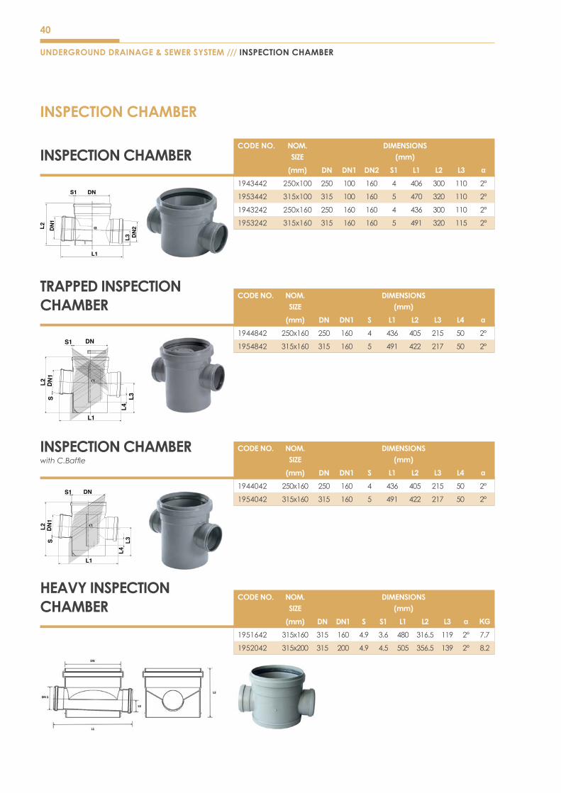
INSPECTION CHAMBER
UNDERGROUND DRAINAGE & SEWER SYSTEM /// INSPECTION CHAMBER
L1
INSPECTION CHAMBER
TRAPPED INSPECTION CHAMBER
INSPECTION CHAMBER with C.Baffle
HEAVY INSPECTION CHAMBER
CODE NO. NOM. SIZE
DIMENSIONS(mm)
(mm) DN DN1 DN2 S1 L1 L2 L3 α
1943442 250x100 250 100 160 4 406 300 110 2°
1953442 315x100 315 100 160 5 470 320 110 2°
1943242 250x160 250 160 160 4 436 300 110 2°
1953242 315x160 315 160 160 5 491 320 115 2°
CODE NO. NOM. SIZE
DIMENSIONS(mm)
(mm) DN DN1 S L1 L2 L3 L4 α
1944842 250x160 250 160 4 436 405 215 50 2°
1954842 315x160 315 160 5 491 422 217 50 2°
CODE NO. NOM. SIZE
DIMENSIONS(mm)
(mm) DN DN1 S L1 L2 L3 L4 α
1944042 250x160 250 160 4 436 405 215 50 2°
1954042 315x160 315 160 5 491 422 217 50 2°
CODE NO. NOM. SIZE
DIMENSIONS(mm)
(mm) DN DN1 S S1 L1 L2 L3 α KG
1951642 315x160 315 160 4.9 3.6 480 316.5 119 2° 7.7
1952042 315x200 315 200 4.9 4.5 505 356.5 139 2° 8.2

41
INSTALLATION GUIDELINES /// UNDERGROUND DRAINAGE & SEWER SYSTEM
INSTALLATION TIPS – RUBBER RING JOINTS (PIPES)
The assembly of one pipe to another may be performed using various methods. One of the most successful methods employsarubberringjoint.Therubberringjointmaybeeitherofintegralsocketdesign(formedasacontinuous,homogeneousentitywiththepipe)oritmayconsistofaseparatesleeve-typecoupling.Thejointprovidesthefollowingadvantages:
• Allowanceforexpansionandcontraction• Reliablyassembledinpoorweatherconditions• Consistent reliability• Flexibility and resiliency• Labor saving and overall economical• Ease of installation
JOINTING METHOD
When the rings are color coded, be sure to consult the pipe manufacturer or their literature for the difference. In all cases, cleanthering,thesocketorthecouplinginterior,especiallythegroove(exceptwhentheringispermanentlyinstalled)andthespigotwitharag,brushorpapertoweltoremoveanydirtorforeignmaterialbeforeassembling.Inspectthering,pipespigotchamber,ringgrooveandsealingsurfacesfordamagesordeformation.Useonlyringswhicharedesignedforandsuppliedwiththepipe.Insertthemasrecommendedbythemanufacturer.
Lubricantshouldbeappliedasspecifiedbythepipemanufacturer.Bacterialgrowth,damagetogasketsorthepipe,mayresult from the use of non-approved lubricants. Use only the lubricant supplied by the pipe manufacturer.
While keeping the lengths in paper alignment, brace the socket and push the spigot into the bell. The spigot should be inserteduntilthereferencemarkonthepipebarrelisevenwiththeedgeofthesocket.
JOINTING METHOD FOR RUBBER RING JOINT
1. Cleandirtandgritfrom
socket
2. Cleantheexteriorofthe
pipe before applying
lubricant
3. Applylubricantonspigot 4. Insertthepipeuntilthe
whiteline
42
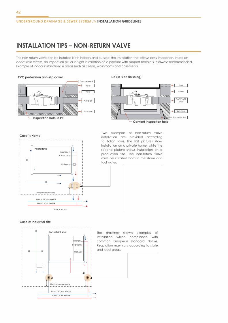
INSTALLATION TIPS – NON-RETURN VALVE
Thenon-returnvalvecanbeinstalledbothindoorsandoutside;theinstallationthatallowseasyinspection,insideanaccessiblerecess,aninspectionpit,orinsightinstallationonapipelinewithsupportbrackets,isalwaysrecommended.Exampleofindoorinstallation:inareassuchascellars,washroomsandbasements.
UNDERGROUND DRAINAGE & SEWER SYSTEM /// INSTALLATION GUIDELINES
PVC pedestrian anti-slip cover
Inspection hole in PP
Concretewall
PVC pipe
Sub-base
Floor
Floor
Cement inspection hole
Concretewall
PVC/PU/PPpipe
Sub-base
Floor
Screed
Lid (in-side finishing)
Case 2: Industrial site
Industrial site
Limit private property
PUBLIC STORM WATER
PUBLIC FOUL WATER
The drawings shown examples ofinstallation which compliance withcommon European standard Norms. Regulation may vary according to state and local areas.
Laundry
Bedroom
Kitchen
Case 1: HomeTwo examples of non-return valveinstallation are provided according to Italian laws. The first pictures showinstallationonaprivatehome,whilethesecond picture shows installation on aproduction site. The non-return valve must be installed both in the storm and foulwater.
PUBLIC STORM WATER
PUBLIC ROAD
PUBLIC FOUL WATER
Limit private property
Laundry
Private Home
Bathroom
Kitchen

43
INSTALLATION TIPS – EASY CLIPS
1) Identifythepointatwhichtheconnectionisrequiredandcleanawayanydebristhatmaybepresent.
2) Drilltheholeperpendiculartotheaxisofthemainpipe
Note:The use of appropriate equipment for centering the pipe will help to prevent errors during this phase. The installation procedure will not be successful if the hole is performed in a decentralized manner. In the case of non-plastic materials (i.e. ceramic or concrete) it is recommended to drill a guide hole (1) initially before completing the hole using a milling tool with a centring drill bit (2). The drilling procedure should always be carried out using water.
In the case of plastic materials, it is best to use a milling tool with an incorporated centring drill bit.
If more than one connection needs to be performed on the same tract of pipe, be sure to leave at least 1 meter between each hole. The installation conditions must always be assessed on a case by case basis: loads, compactness of the terrain, presence of foundations, vehicular traffic, groundwater, etc.
3) Deburrtheedgesoftheholeusingasuitabletool,thisisespecially important for holes made in plastic materials.
4) Lubricatetheseal.5) InserttheClipandtightentheringnut.
INSTALLATION GUIDELINES /// UNDERGROUND DRAINAGE & SEWER SYSTEM
>15cm
Drill at 15cm from the coupling

44
PALING CONNECTORS
Connecting to existing materials quickly and simply, saves installation time. Paling Underground Drainage and Sewer System are manufactured to British and Malaysian standards and are compatible with other standard uPVC drainage systems of the same norminal size.
Paling Underground Drainage System have been designed to meet the needs of today’s drain laying market. It incorporates widerangeoffittingsthatmakesthesystemeasytouseeveninbadweatherconditionsandenablesalltypesofdrainagetobecateredfor.Thesystem’soverallflexibilityoffersconsiderablesavingsinbothlabourandinstallationtime.
Acomprehensiverangeofcomponentsisavailablein(110mm,160mm,200mm,250mmand315mmsizes,thusensuringthatPalingcansupplyalldomestic,commercialandindustrialrequirementsforbothfoulwaterandsurfacewaterdrainageuptomainsewer).
Long Radius Bend Plugged
SocketsShallowAccessChamber Base
Universal Gully Trap
Coupler
Coupler
Bend45°
Bend45°
Gully Trap110mm
Underground PipeBend45°
Bend 45°
Bend 45°
Bend 87½°
Inspection Chamber
Raising Piece
Raising Piece
Aluminium Cover & Frame
Raising Piece
Polypropylene Frame & Cover
DRAINAGE SYSTEM LAYOUT
Paling offers a variety of bends, junctions, adaptors, gullies and access fittings to overcome the most difficult drainage installation.
UNDERGROUND DRAINAGE & SEWER SYSTEM /// DRAINAGE SYSTEM LAYOUT

45
DRAINAGE SYSTEM LAYOUT /// UNDERGROUND DRAINAGE & SEWER SYSTEM
ASSEMBLY HEIGHT GUIDE
Hunter450mmInspectionChamberscanbeinstalledupto1.2mdeep.Riserscanbecutasrequiredtoachievethefinalgroundlevel.
- Easy to install
- High resistance against impact
- ConformtoBS8301
- Withfingerfriendlyremovableplug
- Environmentally-friendly recycled polypropylene
DS50 DS66
Base only 280mm 360mm
Basewith1riser 444mm 524mm
Basewith2risers 608mm 688mm
Basewith3risers 772mm 852mm
Basewith4risers 936mm 1016mm
Basewith5risers 1100mm 1180mm
INSPECTION CHAMBERSProduct Code
Product Code
110mm 160mm
450mm Equal Chamberbase 263mm invert
3SocketsSuppliedwithBlankingPlugs
D550
110mm Blanking Plug
Spare DS56
450mm Unequal Chamberbase 360mm Invert
SideSocketsSuppliedwithBlanking Plugs
DS66
580mm x 580mm Square to Round Access Cover
5Tonneswheelloadsuitspedestrianareas/domesticdriveways(Accepts)
DS65 DS65
Cover and Frame Durable Polypropylene
DurablePolyproylene3.5Tonneswheelloadsuitspedestrianareas/domesticdriveways
DS62
Square Cover and Frame
DurablePolyproplene3.5Tonneswheelloadsuitspedestrian/domesticdriveways
DS76
Raising Piece
164mmeffectiveheight(ForDS50orDS66)
DS58 DS58
Chamberbase Seal
(ForDS66BasetofirstRiseronly) DS67
SHALLOW ACCESSProduct Code
110mm
230mm Equal Chamberbase 140mm Invert
Side Sockets Supplied Blanking Plugs DS71
Raising Piece
(205mmeffectiveheight2risersfrom600moverallheight)
DS72
Cover and Frame
Aluminium DS39
‘O’ Ring to form Sealed Access
(forDS39only) DS40
PVCu - Round
(SealUnit) DS69
PVCu - Square
(SealedUnit) DS68
Shallow Access Cover
390mmx390mmSquaretoRound
3.5Tonneswheelloadsuitspedestrian/domesticdriveways(Accepts)
DS75

46
FREQUENTLYASKEDQUESTIONS
WHAT ARE THE ADVANTAGES OF PVC-U?
PVC-Upipesdonotreactwithchemicalsanddonotconductelectricity.Theyaresafeforuseoutdoorsorin soil that contains a high level of acidity, alkalis or other chemicals. They are also suitable for use indoors orasameanstoconveychemicalsorwasteproducts,withouttheriskofthecontentscorrodingandweakeningtheintegrityofthepipes.Theyarefrequentlyusedinindustrialandlaboratoryapplicationsduetotheircapacitytowithstandhightemperatures.
WHAT ARE THE BENEFITS OF UNDERGROUND PIPE RUBBER RING JOINT?
PalingRubberRingJointisflexibleandoffersa3degreetruedeflectioninanydirection.Thishelpsthepipetoaccommodatesoilsettlementwithoutdamagingthepipeline.Inaddition,theRubberRingJointpermitswidebendingradiusduringcurvatureinstallation.
WHY ARE PVC PIPING SYSTEMS COST EFFECTIVE?
The cost of PVC piping is only a fraction of the cost for products made of other materials. Installation costsarealsolower,becauseofincreasedproductivityandcheapertransportationexpensesduetotheproduct’slowerweight.Savingsarealsorealisedwhenworkisdonetojointhepipingsectionstogether,becausePVCpipingmakesuseofsimplePVCconnectorsandsolventcements,whereasmetalpipingrequiresweldingandexpensivemetalconnectorstobringintooperationaluse.
DO PVC-U FITTINGS LAST LONG?
PVCisstronganddurable,inspiteofitsrelativelylightweight.Asaresult,thismaterialissuitableforalltypesof long-term applications, including indoor, outdoor and buried piping system. It remains strong across a rangeoftemperatures,resultinginfewerburstpipesandreducedmaintenanceissues.Ingeneral,theimpact strength of PVC piping is actually better than that of comparable alternative materials.
ARE THERE ANY MARKINGS ON PALING PIPES?
Palingmarksallofitspipeswiththefollowing:Palinglogo,SIRIMcertification,SIRIMlicensenumber,standardsconformance and year of the standard, nominal size, manufacture date, manufacture shift code, lead-free and quality mark.
UNDERGROUND DRAINAGE & SEWER SYSTEM /// FAQs

47
ABOUT US /// UNDERGROUND DRAINAGE & SEWER SYSTEM
Aliaxisispresentinmorethan40countries.TheGrouphasmorethan100manufacturingandcommercialentitiesandemploysover14,600people.
TheethosoftheGroupallowslocalandglobalknowledgeoftheindustry,regulationsandbuildingpracticestocombineandprovideconsistentlyexcellentcustomerservicetospecifies,consultants,contractors, installers and others.
THE ALIAXIS GROUP IS A LEADING GLOBAL MANUFACTURER AND DISTRIBUTOR OF PRIMARY PLASTIC FLUID HANDLING SYSTEMS USED IN RESIDENTIAL AND COMMERCIAL CONSTRUCTION.
THE ALIAXIS GROUPABOUT
IN ASIA
Malaysia:KualaLumpur
Vietnam:Ho Chi Minh
India:Bangalore, Mumbai & Goa
Singapore
China:Beijing, Shanghai & Guangzhou
ABOUT
PALING INDUSTRIES SDN. BHD. WAS ESTABLISHED IN 1971 TO PRODUCE uPVC PIPES & FITTINGS IN MALAYSIA. OVER THE YEARS IT HAS EXPANDED ITS RANGE TO OTHER SANITARY PRODUCTS AND SYSTEMS LIKE PLASTIC CISTERNS AND OTHER ACCESSORIES.
PALING INDUSTRIES
These systems are suitable for various applications and building types, including domestic, commercial, industrial and civil construction projects. Our products are accurately designed to consistently exceed the performanceaspectsspecifiedunderwidelyrecognizedstandards.
AlongwithISO9001certificationandvariousapprovalsbySIRIMandIKRAM,PalingproductsareaccreditedbyNSF,anauthorityinwaterindustrystandards.
Our products are manufactured under an effective system of inspection, testing, supervision and control.

NOTE : : DATE
Disclaimer
ThisbrochurehasbeencompiledbyPalingIndustriesSdnBhd(“thecompany”)topromotebetterunderstandingofthetechnicalaspectsoftheCompany’s
productstoassistusersinobtainingfromthemthebestpossibleperformance.Thebrochureissuppliedsubjecttoacknowledgmentofthefollowing
conditions:
i) ThebrochureisprotectedbyCopyrightandmaynotbecopiedorreproducedinanyformorbyanymeansinwholeorinpartwithoutpriorconsentin
writingbytheCompany.
ii) Productspecifications,usagedataandadvisoryinformationmaychangefromtimetotimewithadvancesinresearchandfieldexperience.The
Companyreservestherighttomakesuchchangesatanytimewithoutnotice.
iii) CorrectusageoftheCompany’sproductsinvolveengineeringjudgementswhichcannotbeproperlymadewithoutfullknowledgeofalltheconditions
pertainingtoeachspecificinstallation.TheCompanyexpresslydisclaimsallandanyliabilitytoanypersondonebyanysuchpersoninreliancewhether
wholeorpartialuponthewholeoranypartofthecontentsofthisbrochure.
iv) Nooffertotrade,noranyconditionsoftrading,areexpressedorimpliedbytheissueorcontentofthisbrochure.
v) NothinghereinshalloverridetheCompany’sconditionsofSale,whichmaybeobtainedfromtheRegisteredOfficeoranySalesOfficeoftheCompany.
vi) ThisbrochureisandshallremainthepropertyoftheCompany,andshallsurrenderedondemandtotheCompany.
RAINWATERDRAINAGE SYSTEM
P I P E S Y S T E M SSUITABLE FOR BUILDINGS,
HOUSES AND CIVIL CONSTRUCTION PURPOSES.
P I P E S Y S T E M SSUITABLE FOR BUILDINGS,
HOUSES AND CIVIL CONSTRUCTION PURPOSES.
SOIL ,WASTE&VENT
P R E S S U R EP I P I N G S Y S T E M
P I P E S Y S T E M SSUITABLE FOR BUILDINGS,
HOUSES AND CIVIL CONSTRUCTION PURPOSES.
P I P E S Y S T E M SSUITABLE FOR BUILDINGS,
HOUSES AND CIVIL CONSTRUCTION PURPOSES.
HYDROTECHTM
MS3M U L T I - L AY E R P V C - U
P I P E S Y S T E M SSUITABLE FOR CIVIL
CONSTRUCTION PURPOSES AND BUILDINGS.
R A I N WAT E RSYSTEM & GYROJOINT
RAINGUTTERS
P I P E S Y S T E M S
SUITABLE FOR BUILDINGS AND HOUSES
Elegance
Distributed by :
Lot10072,PersiaranMahoganiUtama2Seksyen4,BandarUtamaBatangKali,44300BatangKali,Selangor Darul Ehsan.
T :603-60636888(General)
:603-60570580(Sales)
F :603-60570680
PALING INDUSTRIES SDN BHD (11039 V)
w w w . p a l i n g . c o m . m y
TRUSTED PIPEWORK FOR LIFE