Under the Stormwater green roof the Wrigley Reservoir · the Wrigley Reservoir Geosynthetic ......
68
JUNE/JULY 2010 VOLUME 28 NUMBER 3 Subscribe at www.geosyntheticsmagazine.com Stormwater detention using geosynthetics A new take on sound-barrier walls Geosynthetic reinforcement Is it magic? Building bridges the GRS way
Transcript of Under the Stormwater green roof the Wrigley Reservoir · the Wrigley Reservoir Geosynthetic ......

Subscribe at www.geosyntheticsmagazine.com
Under thegreen roofin northern California
Revivingthe Wrigley Reservoir
Geosyntheticapplicationsin the new I-35W Bridge
More Q’s-&-A’sfrom the GMA Techline
JUNE/JULY 2010VOLUME 28 NUMBER 3
Subscribe at www.geosyntheticsmagazine.com
Stormwater detention using geosynthetics
A new take on sound-barrier walls
Geosynthetic reinforcement
Is it magic?
Building bridges the GRS way
0610GS_Cv1.indd 10610GS_Cv1.indd 1 5/27/10 7:14:42 AM5/27/10 7:14:42 AM

0610GS_Cv1-p11.indd Cv20610GS_Cv1-p11.indd Cv2 5/27/10 7:09:48 AM5/27/10 7:09:48 AM
No matter how you measure performance—best technical support, cost-e ectiveness, product quality, ease of installation, proven reliability or environmental “green” solutions, Strata delivers.
Get started by visiting www.geogrid.com or calling us today at 800-680-7750 or 770-888-6688.You ll gain access to Strata s experience-based answers for all your steep slope, retaining wall, andembankment challenges.
www.geogrid.com Con dence runs deep with Strata.
0610GS_Cv1-p11.indd 10610GS_Cv1-p11.indd 1 5/27/10 7:09:50 AM5/27/10 7:09:50 AM

SOMETIMES IT’S WHAT YOU DON’T SEE THAT MATTERS.AND WHAT YOU MAY NOT SEE, OR KNOW, IS HOW SECURE THE CONNECTION IS BETWEEN THE WALL FACE AND THE GEOGRID REINFORCEMENT.
That connection is a critical element in the overall performance of any
segmental retaining wall. With the Mesa® Retaining Wall Systems,
high-strength Tensar® Geogrid is combined with a patented mechanical
connector, providing structural assurance and installation savings that
surpass frictional-based segmental retaining walls.
For more information on how the Mesa Systems can save you time and
money, call 888-828-5007 or visit www.tensarcorp.com/MESA_GEO
©2010, Tensar International Corporation. MESA is a registered trademark. FP-MGEO4C10
0610GS_Cv1-p11.indd 20610GS_Cv1-p11.indd 2 5/27/10 7:09:50 AM5/27/10 7:09:50 AM

www.geosyntheticsmagazine.com 3
JUNE/JULY 2010VOLUME 28 NUMBER 3
On Site 34 ON THE COVER
Geosynthetic
materials are key
components in the
construction of
this underground
stormwater detention
system. See page 34.
42
16
12 Geosynthetics Market Report The U.S. geosynthetics market is poised for a 2010–2011 comeback. By Jeffrey Rasmussen
16 Geosynthetic reinforcement: Is it magic? Do not rely on magic in engineering. By Dov Leshchinsky
26 Geomembrane cover offers multiple efficiencies A retractable geomembrane cover provides odor control and ease of maintenance. By Jim McMahon
34 How geosynthetic materials are used in an underground stormwater detention system By Terence G. Sheridan
42 MSE walls support laterally loaded drilled shafts A new take on sound-barrier walls. By Jie Han, Robert Parsons, Matthew Pierson, and James Brennan
0610GS_Cv1-p11.indd 30610GS_Cv1-p11.indd 3 5/27/10 7:09:52 AM5/27/10 7:09:52 AM

4 Geosynthetics | June July 2010
In Situ
Geosynthetics ISSN #0882 4983, Vol. 28, Number 3 is published bimonthly by Industrial Fabrics
Association International, 1801 County Road B W, Roseville, MN 55113-4061. Periodicals
Postage Paid at Minneapolis, MN and at additional mailing offi ces. Postmaster: send address
changes to Geosynthetics, County Road B W, Roseville, MN 55113-4061. Return Undeliverable
Canadian Addresses to Station A, PO Box 54, Windsor, ON N9A 6J5. Orders and changes
contact: Tiff any Connor, Circulation Promotions Specialist, Geosynthetics , 1801 County Road B W,
Roseville, MN 55113-4061 Phone 800 225 4324 or +1 651 222 2508, fax +1 651 631 9334 e-mail:
[email protected]. 1-year USA $59, Canada and Mexico $69, all other countries $99, payable
in U.S. funds (includes air mail postage). Reprints: call +1 651 225 6917, [email protected]. Back
Issues: call 800 225 4324, www.ifaibookstore.com.
10
Final Inspection
COMING NEXT ISSUE
10
50
6 Editorial EPA’s coal-ash proposal offers further stimulus.
8 From our readers Comments and questions from
www.geosyntheticsmagazine.com
9 Only on the website
10 Updates In Geosynthetics, you have read about geotextile
tubes in Europe’s first surf reef and how to build
GRS bridges. Here are updates on those two topics.
50 Panorama Geogrids to the rescue in South Africa
New class of certified geo-professionals
Personnel updates
In Memorium: Bernard Myles
52 Geo-Frontiers Watch Check out the short courses that are available
in Dallas next March.
55 Geosynthetic Materials Association Geosynthetics: The present and perspectives
from Mexico. By Andrew Aho
59 Geosynthetic Institute Purging our industry’s dated
test methods and specs. By Bob Koerner
61 Calendar
63 Ad Index
64 Final Inspection Bernard Myles was my friend By Pete Stevenson
IGS Spotlight | “Working together” | Award-winning landfill cap
0610GS_Cv1-p11.indd 40610GS_Cv1-p11.indd 4 5/27/10 7:10:03 AM5/27/10 7:10:03 AM

0610GS_Cv1-p11.indd 50610GS_Cv1-p11.indd 5 5/27/10 7:10:09 AM5/27/10 7:10:09 AM
6 Geosynthetics | June July 2010
The official publication of the
Geosynthetic Materials Association
The official publication of the North
American Geosynthetics Society
PUBLISHER
Mary Hennessy | [email protected]
ASSOCIATE PUBLISHER
Susan R. Niemi | [email protected]
EDITOR
Ron Bygness | [email protected]
ART DIRECTOR
Marti Naughton
GRAPHIC DESIGNER
Cathleen Rose
ADVERTISING SALES
Vivian Cowan, Julia Heath, Sarah Hyland, Paul Montag, Mary Mullowney, Sandy Tapp, Elizabeth Welsh | 800 225 4324
EXHIBIT SALES SPECIALIST
Terry Brodsky | [email protected]
CLASSIFIED ADVERTISING SALES/AD DESIGN
Elizabeth Kaestner [email protected]
ADVERTISING ACCOUNT COORDINATOR
Shelly Arman | [email protected]
CIRCULATION MANAGER
Mary Moore | [email protected]
CIRCULATION PROMOTIONS SPECIALIST
Tiff any Connor | [email protected]
INDUSTRIAL FABRICS ASSOCIATION INTERNATIONAL
1801 County Road B W.Roseville, MN 55113-4061, USA+1 651 222 2508 | 800 225 4324 (U.S. and Canada only) | Fax +1 651 631 9334 | www.ifai.com
EDITORIAL
Geosynthetics is an international, bimonthly publication for civil engineers,
contractors and government agencies in need of expert information on
geosynthetic engineering solutions. Geosynthetics presents articles from
field professionals for innovative, exemplary practice.
Ron Bygness
Editor, Geosynthetics magazine
+1 651 225 6988
© 2010 Industrial Fabrics Association International.
All rights reserved.
EDITORIAL ADVISORY COMMITTEE*
Melody A. Adams | Shaw Environmental Inc., USA
Andrew Aho | GMA, USA
Sam R. Allen | TRI/Environmental, USA
Richard J. Bathurst | Royal Military College, Canada
Witty Bindra | Permathene Pty. Ltd., Australia
David A. Carson | U.S. EPA, USA
Daniele A. Cazzuffi | CESI S.p.A., Italy
Oscar R. Couttolenc | GMA, Mexico
Ronald K. Frobel | R.K. Frobel & Associates, USA
Stephan M. Gale | Gale-Tec Engineering Inc., USA
Han-Yong Jeon | INHA University, Korea
Robert M. Koerner | The Geosynthetic Institute, USA
Robert E. Mackey | S2L Inc., USA
Kent von Maubeuge | NAUE GmbH, Germany
Jacek Mlynarek | SAGEOS, Canada
Dhani Narejo | Caro Engineering LLC, USA
Roy J. Nelsen | ErosionControlBlanket.com Inc., USA
Jim Olsta | CETCO, USA
Ian D. Peggs | I-Corp International, USA
Greg N. Richardson | RSG & Associates Inc., USA
Marco A. Sánchez | ML Ingeniería, Mexico
Mark E. Smith | RRD International, USA
L. David Suits | NAGS, USA
Gary L. Willibey | ESP/SKAPS Industries, USA
Aigen Zhao | Syntec Corp., USA
*The Editorial Advisory Committee reviews selected papers,case histories, and technical editorial copy in its areas of expertise. Individual advisors do not review every submission. Statements of fact and opinion are the author’s responsibility alone, and do not imply the viewpoints of Geosynthetics, its Editorial Advisory Committee, editors,or the association.
EPA’s coal-ash proposaloff ers further stimulus
Earlier this year, I was talking with a geosynthetics sales manager
who offered a brief description of the economic landscape: “We
hung in there during 2009 and now we see brighter things this
year and in 2011.” Mark those words, then read our report on the U.S.
geosynthetics marketplace “poised for a comeback” (page 12).
Then in May, this arrived. The U.S. Environmental Protection
Agency (EPA) finally unleashed its long-awaited, 563-page tome, “Coal
Combustion Residuals–Proposed Rule.”
(In plain English: What are we going to do about the ash byproduct
from coal power plants? Yes, this is the same coal-ash sludge that came
to national attention in December 2008 when it covered millions of
cubic yards of land and water following an impoundment failure in
Kingston, Tenn.)
The EPA’s proposal is lengthy, but here is a key section regarding
coal-ash containment: “… will ensure for the first time that protective
controls, such as liners and groundwater monitoring, are in place at new
landfills to protect groundwater and human health. Existing surface
impoundments will also require liners …”
Of course, we are now in the midst of the back-and-forth, the 90-day
commentary period, and perhaps even legislative action from Congress.
But all of the momentum is in place for what is likely another huge
milestone in the history of geosynthetics.
Talk about stimulus!
There is currently a task group of members from the Geosynthetic
Materials Association (GMA) focused on the EPA’s proposals, working
to ensure that liner language is adopted in its best light. Now would be a
great time to lend this group your professional and financial support.
GMA’s government-relations program has advocated tenaciously
for these regulations. With implementation of the EPA’s proposals,
GMA managing director Andrew Aho said he estimates a potential
economic impact in the neighborhood of $350 million during the next
five years or so.
And that is a very nice neighborhood. Stimulating indeed!
0610GS_Cv1-p11.indd 60610GS_Cv1-p11.indd 6 5/27/10 7:10:09 AM5/27/10 7:10:09 AM

reinforced concrete retaining wall
Development of fabric form more strength and durability
Institutions: SAENAL tex tech, KOLON, KTDI, FITI, INHA University
Period: June 2009 – May 2011
Reinforcement: geogrid, rebar + anchor block
0610GS_Cv1-p11.indd 70610GS_Cv1-p11.indd 7 5/27/10 7:10:11 AM5/27/10 7:10:11 AM

8 Geosynthetics | June July 2010
Subgrade enhancement geotextilesEditor’s Note: An August 2009 article briefl y described a new California DOT (Caltrans) guide
for using subgrade enhancement geotextiles. In a comment on this article, the reader poses a
question, which is answered by (a) the author of the Caltrans guide and (b) me.
To read the original article and a link to this guide, search “subgrade enhancement geotextiles”
at: www.geosyntheticsmagazine.com.
Comment: SEG Guide error?From: Wendel B. | Jan. 5, 2010
After reviewing your guide for SEG and having to respond to an engineer
who has used your table for a local project, I wish to draw your attention to
what I believe is an error within the property table. The puncture strength
requirements [seem] way too high for woven geotextile fabrics and I do not
recognize the ASTM number used.
Thank you.
Re: SEG Guide error?From: Ron Bygness, editor, Geosynthetics magazine | Jan. 21, 2010
Thank you for your comment.
Here is a response from Imad Basheer, California DOT/Office of Pavement Design
and author of “Guide for designing: Subgrade enhancement geotextiles”:
The puncture resistance values were based on the AASHTO M288-06 standard
specifications for “Geotextile specifications for highway applications” and the
FHAW publication No. FHWA HI-95-038 and its updated version FHWA NHI-06-
116 titled “Geosynthetic design and construction guidelines.” The puncture
resistance test is given in ASTM D6241.
One further clarification from Geosynthetics editor, Ron Bygness:
Per current AASHTO M288 specifications, ASTM D6241 has replaced D4833.
D4833 is no longer recognized by ASTM Committee D35 on Geosynthetics as an
acceptable geotextile test method.
Please see the GMA (page 51) and Final Inspection (page 56) columns in the
February/March 2010 issue of Geosynthetics magazine for complete details
(http://geosyntheticsmagazine.com/issues/28/1).
Seismic performanceEditor’s Note: The August 2009 issue included an article regarding seismic performance of
geocells by Prof. Dov Leshchinsky. A reader off ered a compliment and a request.
To read this original artile by Dr. Leshchinsky, go to: “seismic performance” at:
www.geosyntheticsmagazine.com.
CommentFrom: Slobodan Riger, Alfa Invest | Aug. 28, 2009
Excellent presentation. We will be interested [in] analysis for higher walls, 5-8m,
and the load of highway on the top.
Comments and letters can contain opinions of
individuals who are writing and do not necessarily
reflect the views of Geosynthetics magazine or the
Industrial Fabrics Association International.
Contact us at www.geosyntheticsmagazine.com
FROM OUR READERS
Comment on any
article in Geosynthetics at:
www.geosyntheticsmagazine.com
OR
Send a letter to the editor at:
0610GS_Cv1-p11.indd 80610GS_Cv1-p11.indd 8 5/27/10 7:10:11 AM5/27/10 7:10:11 AM
www.geosyntheticsmagazine.com 9
www.geosyntheticsmagazine.comONLY ON THE WEB
Slope anglesEditor’s Note: In the June 2009 issue (page
56), Tim Stark, an engineering professor at
the University of Illinois, answered a question
regarding geosynthetic-lined slopes. Prof.
Ed Kavazanjian’s comments off er further
information on the subject.
Q: Is there a maximum
slope angle for geosynthetic
lined slopes?
A: Yes there is, and the slope angle
should not exceed the lowest
geosynthetic interface friction angle,
δ, of the system. The slope angle
should not exceed δ because this
condition can/will lead to tension
developing in the geosynthetics and
possibly progressive failure of the
slope. Geosynthetics will stretch and
possibly tear under tension because
they are not designed to be under
tension. The only geosynthetic that
is designed to be under tension
are geosynthetic reinforcement
products, such as geogrids and high-
strength geotextiles.
CommentFrom: Ed Kavazanjian, Arizona
State University | Aug. 15, 2009
Tim Stark’s [answer] on restricting the
inclination of a geosynthetic lined slope
to the lowest interface friction angle of
the system only applies to the stability
of veneer slopes where the geometry
appoaches those of an infinite
slope. For instance, there are many
landfills where the lowest interface
friction angle of the side slope is less
than the slope angle. These landfills
are generally filled incrementally, in
horizontal lifts subject to restrictions
on lift height and breadth to
maintain stability. Technically, a bowl-
shaped landfill with an interface friction
angle of zero could be filled in uniform
horizontal lifts maintaining stability.
>>Continued on page 54 >>
BLOGS
Check out all of our blogs by clicking on the GeoBlog button at:
www.geosyntheticsmagazine.com
Geosynthetics world hails new coal-ash regulations
The GMA bandwagon is rolling, jump on now
On board with IFAI Expo AsiaAsia 2011
INDUSTRY NEWS
EPA announces plans to regulate coal ashTo read this article, search “regulate coal ash” at:
www.geosyntheticsmagazine.com
ASCE inducts new class of certifi ed geo-professionalsTo read this article, search “ASCE inducts” at:
www.geosyntheticsmagazine.com
Daniel Selander promoted at Thrace-LINQTo read more, search “Thrace-LINQ” at: www.geosyntheticsmagazine.com
Sam Allen receives ASTM awardTo read more, search “ASTM recognizes” at:
www.geosyntheticsmagazine.com
BOOKSTORE
“Designer’s Forum: 2004–2008” and “How to buy, design, and build retaining walls”Both of these popular, new compilations are now
available through the IFAI Bookstore:
www.geosyntheticsmagazine.com
Click on resources/bookstore
0610GS_Cv1-p11.indd 90610GS_Cv1-p11.indd 9 5/27/10 7:10:12 AM5/27/10 7:10:12 AM

10 Geosynthetics | June July 2010
UPDATES
NOV. 2, 2009Surf reef opens after year delay
“Geotextile bags help create Europe’s first artificial surf reef” (geosyntheticsmagazine.com | Nov. 6, 2009):
A £3M ($5M U.S.) artificial reef project expected to open a year ago was finally unveiled Nov. 2. near the seaside coastal village of Boscombe in southern England. Construction had been delayed for months by bad weather.
The reef, which more than doubled in cost since original estimates, was built by New Zealand-based ASR to enhance off-shore waves. It is part of an overall £11M ($17M U.S.) regeneration of the Bournemouth area’s seafront, including improvements at the coastal suburb of Boscombe.
The artificial reef was created to improve surfing conditions by using 55 sand-filled geotextile bags that were strategically placed 225m (740ft) off the coastline.
NOV. 6, 2009Council seeks to recoup reef cost
Europe’s first artificial surf reef incurred an additional cost of more than £250,000 ($386,000 USD) … an audit committee will meet to discuss the reef.
A specialist team from Plymouth University has been enlisted to monitor the reef’s per-formance, to assess whether it is delivering the surfing conditions expected.
NOV. 27, 2009Surf beach huts still unsold
Retro-style “surf pods” in the renovated 1950s Overstrand building, beachside in Boscombe, went on sale for £64,995–£89,995 ($100,000-$140,000 USD).
Despite a flurry of interest at a sales event (May 2009), only eight of the 43 units have been sold.
FEB. 9, 2010Boscombe reef to host first surf contest
The Sorted Surf Festival will feature a number of categories for professional surfers March 20–21. The contest will be a chance to silence critics who say the reef does not work and is in the wrong place.
FEB. 26, 2010Reviews and festival
Plymouth University, home of the UK’s first marine institute, is assessing the quality of the waves and the number of days suitable for surfing.
There has been a mixed response to the reef’s success from surfers who have tried waves … in March, the reef waves are to be featured during The Sorted Surf Festival.
MARCH 22, 2010Reef contest hailed as a success
An estimated 5,000 people turned out for the Sorted Surf Festival, held on the redevel-oped Boscombe seafront during the week-end. Event organizers said they received positive feedback.
APRIL 8, 2010South coast ‘expects busy summer’
A busy Easter holiday weekend offered expectations for a busy summer at this redeveloped coastal area in south England.
Local tourist officials said hotel bookings are up, foreign travel appears to still be down because of the recession, and so-called “staycations” look like a boost for U.K. travel destinations.
The seaside Boscombe area of Bournemouth is banking on those trends, along with its centerpiece surf reef to increase the number of tourists this summer.
MAY 18, 2010Surf reef is only ‘4 out of 10’
A marine expert yesterday confirmed what its critics have been saying for months—Europe’s first artificial surf reef is not working in the way civic chiefs had envisaged.
Mark Davidson from Plymouth University gave the £4 million Boscombe tourist attraction a score of just 4 out of 10 in a scale of its success.
First artifi cial surf reef in Europe
Delays, cost, performance are key issues for reef
A one-year delay in construction, with nearly double the initial cost estimates, and surf-
ing conditions not meeting expectations have all been part of the experience for the first
artificial surfing reef in Europe, which opened earlier this year off the south coast of
England. Geosynthetics referenced this project in its October/November 2008 issue.
The reef, built with 55 sand-filled geotextile bags, is part of an overall beach rejuve-
nation project in Boscombe, Bournemouth, England. As reported in the British media,
here are highlights from the past 8 months:
TOP Geotextile tubes were placed on the
seafloor, creating a “surf reef” off the south coast
of England. BOTTOM Geotextile tube compo-
nents were arranged on a barge in preparation
for installation last year.
>> For more, search tubes at
www.geosyntheticsmagazine.com
0610GS_Cv1-p11.indd 100610GS_Cv1-p11.indd 10 5/27/10 7:10:15 AM5/27/10 7:10:15 AM

www.geosyntheticsmagazine.com 11
Building bridges the geosynthetic-reinforced soil wayFrom Defiance County, Ohio, to Yamhill
County, Oregon, building bridges using
geosynthetic-reinforced soil is gaining
popularity for its effectiveness, efficiency,
and time-saving simplicity.
This methodology was first featured in
Geosynthetics in August 2006, with a follow-
up in April 2008 (see links below). Defiance
County Engineer Warren Schlatter and
his crews, with initial assistance from the
Federal Highway Administration (FHWA),
have now constructed 16 such bridges in the
rural northwestern Ohio county.
Now, Bill Gille and his Yamhill County
(Ore.) crews are following in a similar,
successful style. Late last year, the small
Laughlin Road Bridge was reconstructed
in much the same manner as those in
Ohio, by building up the bridge abut-
ments using alternate layers of geotextiles
and compacted fill.
County Engineer Gille described the
process as similar to a layer cake, building
layer upon layer until you get to the top.
“Then you set your bridge on it,” he said.
Yamhill County is located in northwest-
ern Oregon.
Building bridges in this fashion allows
construction in an adaptable, efficient
manner, without pouring tons of con-
crete. It’s also quick. Schlatter described
how his crew built one bridge abutment
in Defiance County in three days. A cast-
in-place structure could require weeks.
http://geosyntheticsmagazine.com/
repository/2/2481/0806gs_digitaledition.pdf
http://geosyntheticsmagazine.com/articles/0408_f3_
bridges.html
Geosynthetics readers have seen the progress
of GRS bridges in Defiance County, Ohio. Now,
Yamhill County, Oregon, is following suit.
>> For more, search GRS bridges at
www.geosyntheticsmagazine.com
0610GS_Cv1-p11.indd 110610GS_Cv1-p11.indd 11 5/27/10 7:10:18 AM5/27/10 7:10:18 AM

12 Geosynthetics | June July 2010
0610GS_p12-31.indd 120610GS_p12-31.indd 12 5/27/10 7:10:42 AM5/27/10 7:10:42 AM

www.geosyntheticsmagazine.com 13
Unfi nished business
U.S. geosynthetics market is poised for a comeback in 2010-11By Jeff rey Rasmussen
Jeff Rasmussen is market research manager at
the Industrial Fabrics Association International
(IFAI), +1 651 225 6967, [email protected].
Source: IFAI February 2010 Geosynthetic Climate Survey
of geosynthetic suppliers and distributors.
2009 U.S./Canada Geosynthetic Sales
by Type of GeosyntheticFigures are annual and based on mean values.
Geotextiles
34%
Geogrids
22%
Geomembranes
22%
Drainage
composites
4%
Other
18%
>> See the EPA’s announcement
regarding coal-ash disposal:
http://geosyntheticsmagazine.com/
articles/050410.html
While U.S. geosynthetics manufacturers and distributors assess 2009’s
lackluster performance, they can also look forward to the possibility
of meaningful improvements before the end of this year.
Sales in 2009 were down about 4-5%. However, a slow but steady growth is expected
this year and into 2011.
The decrease in sales and profit margins for U.S. geosynthetics manufactur-
ers and distributors in 2009 was due primarily to the lack of publicly funded
projects, state budget deficits, and the tight credit and lending situation.
The significant downturn in the economy was the driving force behind
tight credit conditions and a widespread lack of publicly funded projects
across the United States. Because of these issues, contractors and state
transportation departments are expected to be cautious in hiring
and spending decisions while they wait for Congress to pass a new
federal transportation bill, which could happen as soon as autumn
2010. Overall, the value of highway, street, and bridge construction
in 2009 was about $84.8 billion, up 3.6% from 2008. It is expected to
reach about $90.5 billion in 2010, up about 7% over 2009.
Uncertainty regarding the multiyear federal transportation reau-
thorization bill and future growth of the overall U.S. economy—and
the availability of stimulus money—will determine if the U.S. market
materializes into a growth year for many U.S. geosynthetics manufacturers,
suppliers, and distributors in 2010. To date, more than 77% of approximately
$50 billion dollars in stimulus funds has been committed to road and bridge
construction projects, but only 4 billion, or 16% of the total funding available, has
been paid to contractors. So, there is much unfinished work ready for completion in
2010. This should bode well for improving the sales and profit margin prospects for
U.S. geosynthetics manufacturers and distributors.
History Geosynthetics is the term used to describe a family of predominantly polymeric
products used to solve civil engineering problems. The term encompasses eight main
product categories: geotextiles, geogrids, geonets, geomembranes, geosynthetic clay
liners, geofoam, geocells (cellular confinement), and geocomposites.
The polymeric nature of the products makes them suitable for use in the ground
where high levels of durability are required. Properly formulated, however, they can
also be used in exposed applications.
The use of geosynthetics has expanded rapidly into nearly all areas of civil, geotechni-
cal, environmental, coastal, and hydraulic construction. Many durable polymers (plastics)
0610GS_p12-31.indd 130610GS_p12-31.indd 13 5/27/10 7:10:48 AM5/27/10 7:10:48 AM
14 Geosynthetics | June July 2010
common to everyday life are found in geo-
synthetics. The most common are polyole-
fins and polyester, although rubber, fiber-
glass, and natural materials are sometimes
used; however, more than 90% of geosyn-
thetics are made of polypropylene.
Since their introduction in the late
1960s, geosynthetics have proven versa-
tile and cost-effective ground modifica-
tion materials. Geosynthetics also have
become essential elements as barriers in
environmental and hydraulic applications.
There are more than 40 manufacturers of
geosynthetics that provide products for
the North American marketplace—more
than half located in the southeastern U.S. or
Texas. The industry provides about 12,000
jobs in the U.S. in manufacturing, fabrica-
tion, distribution, and installation.
A competitive climate Results from IFAI’s geosynthetics man-
ufacturer/distributor climate survey in
February 2010 showed a very competitive
environment for geosynthetics players in
2009, driven largely by the reduced ex-
penditures and budgets in state and local
governments, a continued slow economy
and market growth, and higher raw mate-
rial and energy prices.
Trends and their impact on the 2009
U.S. geosynthetics market, as cited by
manufacturers and distributors in IFAI’s
survey, show a range of difficult challenges.
Increased competition pushed prices lower
by as much as 5-10%, resulting in thinner
profit margins. With the market shrinking
plus industry consolidation, there were
market opportunities for some, but others
reduced operations and became more fo-
cused, or closed their doors altogether.
With less spending on infrastructure
and roads, there were fewer projects, and
sales dropped by as much as 40%. High
raw material prices further reduced sales
and profit margins. With customers also
experiencing tight cash positions, they
Since their introduction
in the late 1960s,
geosynthetics have
proven versatile and
cost-eff ective ground
modifi cation materials.
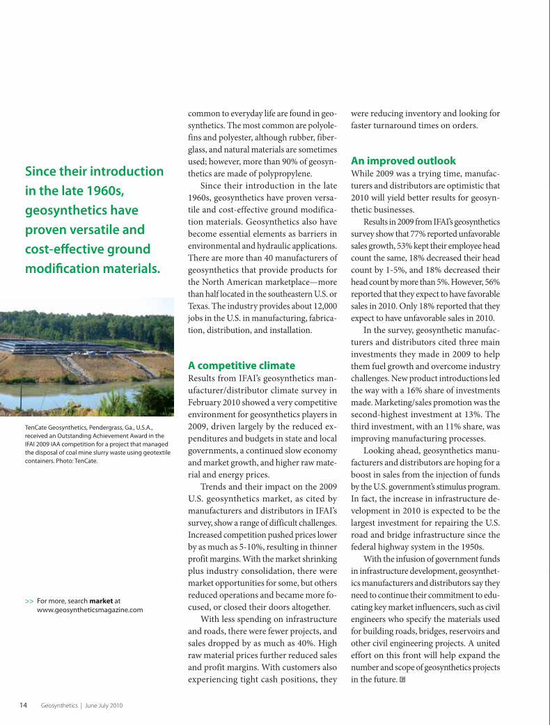
TenCate Geosynthetics, Pendergrass, Ga., U.S.A.,
received an Outstanding Achievement Award in the
IFAI 2009 IAA competition for a project that managed
the disposal of coal mine slurry waste using geotextile
containers. Photo: TenCate.
>> For more, search market at
www.geosyntheticsmagazine.com
were reducing inventory and looking for
faster turnaround times on orders.
An improved outlook While 2009 was a trying time, manufac-
turers and distributors are optimistic that
2010 will yield better results for geosyn-
thetic businesses.
Results in 2009 from IFAI’s geosynthetics
survey show that 77% reported unfavorable
sales growth, 53% kept their employee head
count the same, 18% decreased their head
count by 1-5%, and 18% decreased their
head count by more than 5%. However, 56%
reported that they expect to have favorable
sales in 2010. Only 18% reported that they
expect to have unfavorable sales in 2010.
In the survey, geosynthetic manufac-
turers and distributors cited three main
investments they made in 2009 to help
them fuel growth and overcome industry
challenges. New product introductions led
the way with a 16% share of investments
made. Marketing/sales promotion was the
second-highest investment at 13%. The
third investment, with an 11% share, was
improving manufacturing processes.
Looking ahead, geosynthetics manu-
facturers and distributors are hoping for a
boost in sales from the injection of funds
by the U.S. government’s stimulus program.
In fact, the increase in infrastructure de-
velopment in 2010 is expected to be the
largest investment for repairing the U.S.
road and bridge infrastructure since the
federal highway system in the 1950s.
With the infusion of government funds
in infrastructure development, geosynthet-
ics manufacturers and distributors say they
need to continue their commitment to edu-
cating key market influencers, such as civil
engineers who specify the materials used
for building roads, bridges, reservoirs and
other civil engineering projects. A united
effort on this front will help expand the
number and scope of geosynthetics projects
in the future. G
0610GS_p12-31.indd 140610GS_p12-31.indd 14 5/27/10 7:10:52 AM5/27/10 7:10:52 AM

0610GS_p12-31.indd 150610GS_p12-31.indd 15 5/27/10 7:10:55 AM5/27/10 7:10:55 AM

16 Geosynthetics | June July 2010
FIGURE 1 An excavator perched on top of an unreinforced sandy
slope during deconstruction of the Indian River Inlet Bridge (IRIB)
0610GS_p12-31.indd 160610GS_p12-31.indd 16 5/27/10 7:10:55 AM5/27/10 7:10:55 AM

www.geosyntheticsmagazine.com 17
Dr. Dov Leshchinsky is a professor
in the Department of Civil and
Environmental Engineering at the
University of Delaware.
Photos courtesy of the author
Geosynthetic reinforced walls and steep slopes: Is it magic?By Dov Leshchinsky
Introduction
The history of humankind indicates that most people,
arguably, embrace magic. Adding exotic ceremonies turns
magic into voodoo.
While magic is based on uncritical thinking, relying on it in
engineering is undesirable because it could lead to overly expensive
structures or, worse, unsafe practice. Hence, designers use rules
stemming from mechanics that follow the laws of physics. Often
these rules are augmented by practice that originates in art.
“Art” here should not be equated with “guessing,” but with
“experience.” As an example, experience may imply maximum
vertical spacing between geosynthetic layers or maximum height
of a reinforced structure. While the mechanics may be applicable
to any spacing or height, experience indicates that large spacing
may lead to poor construction or that tall walls/slopes may undergo
compression leading to unaccounted parasitic loads. Hence, art is
part of engineering but it is not a substitute for mechanics.
In the realm of geosynthetic reinforced walls and steep slopes,
one often realizes that the measured force or, more correctly, strain,
in the reinforcement is far smaller than expected. “Expected” means
predicted by mechanics, i.e., statics.
To an engineer this disagreement could be puzzling. If one adopts
such data uncritically, considering it as a Rosetta stone, one is embracing
magic over mechanics. Adopting unexplained behavior of reinforced
soil essentially shortcuts engineering and may lead to failures.
The purpose of this article is to examine an apparent magic
related to measured reinforcement force. A variation of a cli-
ché could be, “If the magic is published, it becomes a fact.” It is
important to critically review the apparent magic before it becomes
a “fact” adopted in design.
Sandcastles Soil is strong in compression but has virtually no strength in tension.
Geosynthetics are relatively strong in tension. Combining the two
materials produces a composite structure that is strong under both
compression and tension.
0610GS_p12-31.indd 170610GS_p12-31.indd 17 5/27/10 7:10:59 AM5/27/10 7:10:59 AM
18 Geosynthetics | June July 2010
Reinforced walls and steep slopes
This means that reinforced earth
structures can be constructed steeply and
act as retaining structures. In fact, dry non-
cemented sand alone cannot be steeper
than its internal angle of friction, typically
less than 40°. Mechanics agree with this
measured limit on steepness of dry sand
slopes. Often this limit is termed “angle
of repose.”
Sandcastles serve as an example in
which—at face value—the rule of angle
of repose is invalidated. Sandcastles are
formed with steep slopes, even negative
batters and overhanging cliffs that are
realistically sculptured. This magical
phenomenon is observed in wet sand, a
cohesionless material and without inclu-
sion of reinforcement.
Those who question the apparent reality
of sandcastles would wonder how one can
sculpt details in unreinforced, cohesion-
less material that is in conflict with basic
mechanics. This apparent conflict with
mechanics is a serious issue, well beyond
child’s play, because mechanics provide the
foundation for geotechnical design.
One more important observation:
Sandcastles collapse when moisture content
increases with high tide or heavy rainfall.
Sandcastles are not durable structures!
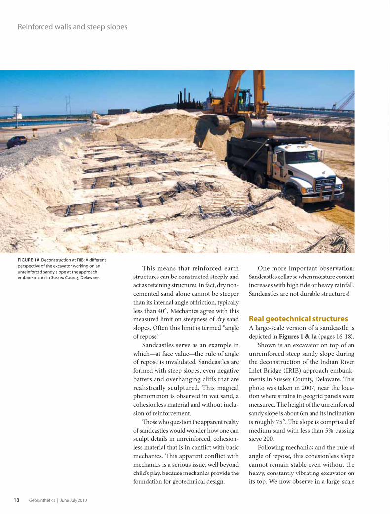
Real geotechnical structures A large-scale version of a sandcastle is
depicted in Figures 1 & 1a (pages 16-18).
Shown is an excavator on top of an
unreinforced steep sandy slope during
the deconstruction of the Indian River
Inlet Bridge (IRIB) approach embank-
ments in Sussex County, Delaware. This
photo was taken in 2007, near the loca-
tion where strains in geogrid panels were
measured. The height of the unreinforced
sandy slope is about 6m and its inclination
is roughly 75°. The slope is comprised of
medium sand with less than 5% passing
sieve 200.
Following mechanics and the rule of
angle of repose, this cohesionless slope
cannot remain stable even without the
heavy, constantly vibrating excavator on
its top. We now observe in a large-scale
FIGURE 1A Deconstruction at IRIB: A different
perspective of the excavator working on an
unreinforced sandy slope at the approach
embankments in Sussex County, Delaware.
0610GS_p12-31.indd 180610GS_p12-31.indd 18 5/27/10 7:11:02 AM5/27/10 7:11:02 AM

Looking for a better solution?
For over 130 years, Maccaferri has been controlling the forces of erosion and retaining the earth’s soil. We’ve learned a lot since 1879 and apply that knowledge to every product and every project.
We offer multiple solutions for base and slope reinforcement. Our extensive line of geogrids and turf reinforcement mats provide outstanding performance in reliability and quality at an exceptional value.
Maccaferri strives to provide a cost effective and dependable solution to every project. We can help you save time and money.
Engineering a better solutionwww.maccaferri-usa.com ∙ 800-638-7744
0610GS_p12-31.indd 190610GS_p12-31.indd 19 5/27/10 7:11:06 AM5/27/10 7:11:06 AM
20 Geosynthetics | June July 2010
Reinforced walls and steep slopes
structure the same phenomenon as in
sandcastles—a steep unreinforced slope.
One can attribute the observed
phenomenon in Figures 1/1a to magic.
However, there is a physical explanation
that can dispel the apparent magic. Soil
matrix suction due to moisture in the sand
effectively produces apparent cohesion. This
cohesion keeps sandcastles and even larger
structures stable. In fact, this phenomenon
has been studied using centrifugal model-
ing. Such studies show that increase in the
sand’s moisture content (e.g., due to rainfall)
diminishes the cohesion resulting in col-
lapse of the sandy steep slope.
Imagine that geosynthetic layers had
been installed in the unreinforced slope
in Figures 1/1a. Considering that the
unreinforced slope seems stable, the ex-
pected mobilized strains in the installed
layers would be zero, as it is not needed
for stability.
In reality, perhaps small values of
strains may exist at random locations along
reinforcement layers, likely induced by
compaction and differential movements
of backfill during construction. However,
substantial strains, in the order of 3–5%,
were measured in the geogrids embedded
in the adjacent reinforced sand wall.
Unlike the slope, over which the ex-
cavator operated for a few hours, where
no precipitation occurred, the reinforced
wall was subject to many rainfall events in
its life. These events caused the moisture
content in the sand to increase and the
apparent cohesion to vanish. The dormant
reinforcement was activated, resulting in
substantial mobilization of its strength.
Most importantly, the wall structure
remained intact because its design did not
rely on magic.
The observation related to the Indian
River Bridge is commonly noticed in
construction. It is presented not to warn
designers to ignore cohesion, as this should
be an obvious practice in design of geogrid-
reinforced walls. It is presented to warn
engineers who monitor gages in walls to
realize that smaller-than-expected mea-
sured forces are not necessarily because
the reinforcement is excessively strong
but because an apparent cohesion renders
a stable system where the reinforcement
is dormant.
Any significant increase in moisture
may diminish the apparent cohesion, mak-
ing the small force observation inherently
unreliable in the context of design. What
appears as magic is actually due to appar-
ent cohesion, which is dependent on the
moisture content of the backfill.
Impact of apparent cohesionThe reality observed in Figures 1 & 1a
(pages 16-18) was attributed to an apparent
cohesion of sand.
Using an acceptable slope stability
method, log spiral analysis, one can relate
the apparent cohesion required to render a
“stable” slope, albeit without the surcharge
induced by the excavator.
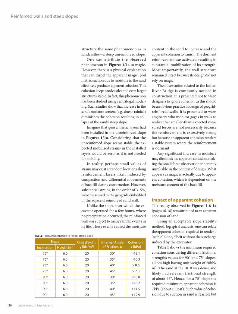
Table 1 shows the minimum required
cohesion considering different frictional
strengths values for 90° and 75° slopes,
all 6m high having unit weight of 20kN/
m3. The sand at the IRIB was dense and
likely had relevant frictional strength
of about 45°. Hence, for a 75° slope the
required minimum apparent cohesion is
7kPa (about 150psf). Such value of cohe-
sion due to suction in sand is feasible but
TABLE 1 Required cohesion to render stable slope
Slope Unit Weight,
γ [kN/m3]
Internal Angle
of Friction, φ
Cohesion,
c [kPa]Inclination Height [m]
75° 6.0 20 30° >12.1
75° 6.0 20 35° >10.3
75° 6.0 20 40° > 8.6
75° 6.0 20 45° > 7.0
90° 6.0 20 30° >18.0
90° 6.0 20 35° >16.2
90° 6.0 20 40° >14.5
90° 6.0 20 45° >12.9
0610GS_p12-31.indd 200610GS_p12-31.indd 20 5/27/10 7:11:06 AM5/27/10 7:11:06 AM

w w w . C E T C O . c o m
900 Northbrook Drive Suite 320Trevose, PA 19053 215.357.0630For more information on CETCO Contracting Services visit www.cetco.com/ccs
CETCO CONTRACTING SERVICES
GEO-ENVIRONMENTAL CONTRACTING IN:Waste ContainmentRemediationCivil/GeotechnicalSediment RemediationReinforced EarthWater roo n Erosion ControlStormwater ana ementHydraulicsGreenroofsSustaina le esi n
CETCO Contracting Services is a true turn-key provider, offering a full range of geo-environmental contracting services, design-build construction and value engineering around the world. Our experience spans all types of geosynthetic materials and some of the most challenging contracting jobs, making CETCO Contracting Services a true single source provider.
0610GS_p12-31.indd 210610GS_p12-31.indd 21 5/27/10 7:11:07 AM5/27/10 7:11:07 AM
22 Geosynthetics | June July 2010
should be considered completely unreliable
and ignored in design.
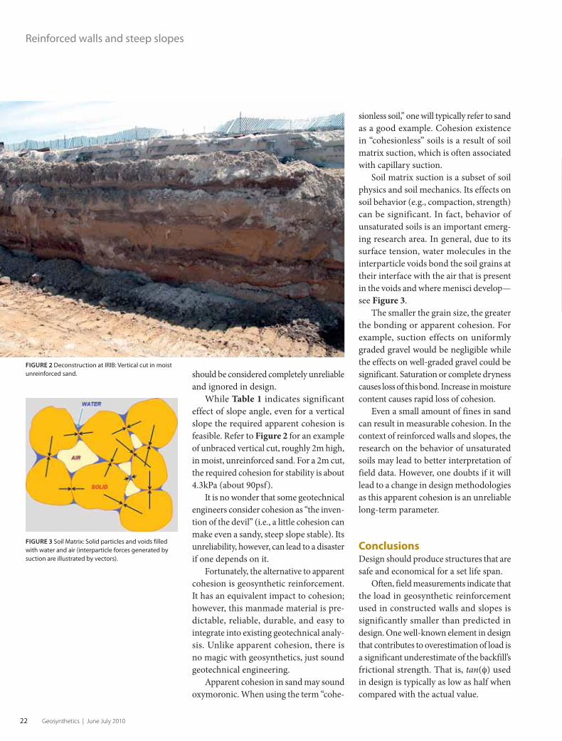
While Table 1 indicates significant
effect of slope angle, even for a vertical
slope the required apparent cohesion is
feasible. Refer to Figure 2 for an example
of unbraced vertical cut, roughly 2m high,
in moist, unreinforced sand. For a 2m cut,
the required cohesion for stability is about
4.3kPa (about 90psf).
It is no wonder that some geotechnical
engineers consider cohesion as “the inven-
tion of the devil” (i.e., a little cohesion can
make even a sandy, steep slope stable). Its
unreliability, however, can lead to a disaster
if one depends on it.
Fortunately, the alternative to apparent
cohesion is geosynthetic reinforcement.
It has an equivalent impact to cohesion;
however, this manmade material is pre-
dictable, reliable, durable, and easy to
integrate into existing geotechnical analy-
sis. Unlike apparent cohesion, there is
no magic with geosynthetics, just sound
geotechnical engineering.
Apparent cohesion in sand may sound
oxymoronic. When using the term “cohe-
sionless soil,” one will typically refer to sand
as a good example. Cohesion existence
in “cohesionless” soils is a result of soil
matrix suction, which is often associated
with capillary suction.
Soil matrix suction is a subset of soil
physics and soil mechanics. Its effects on
soil behavior (e.g., compaction, strength)
can be significant. In fact, behavior of
unsaturated soils is an important emerg-
ing research area. In general, due to its
surface tension, water molecules in the
interparticle voids bond the soil grains at
their interface with the air that is present
in the voids and where menisci develop—
see Figure 3.
The smaller the grain size, the greater
the bonding or apparent cohesion. For
example, suction effects on uniformly
graded gravel would be negligible while
the effects on well-graded gravel could be
significant. Saturation or complete dryness
causes loss of this bond. Increase in moisture
content causes rapid loss of cohesion.
Even a small amount of fines in sand
can result in measurable cohesion. In the
context of reinforced walls and slopes, the
research on the behavior of unsaturated
soils may lead to better interpretation of
field data. However, one doubts if it will
lead to a change in design methodologies
as this apparent cohesion is an unreliable
long-term parameter.
Conclusions Design should produce structures that are
safe and economical for a set life span.
Often, field measurements indicate that
the load in geosynthetic reinforcement
used in constructed walls and slopes is
significantly smaller than predicted in
design. One well-known element in design
that contributes to overestimation of load is
a significant underestimate of the backfill’s
frictional strength. That is, tan(φ) used
in design is typically as low as half when
compared with the actual value.
FIGURE 3 Soil Matrix: Solid particles and voids filled
with water and air (interparticle forces generated by
suction are illustrated by vectors).
FIGURE 2 Deconstruction at IRIB: Vertical cut in moist
unreinforced sand.
Reinforced walls and steep slopes
0610GS_p12-31.indd 220610GS_p12-31.indd 22 5/27/10 7:11:07 AM5/27/10 7:11:07 AM

For more than 25 years, Typar® Geotextiles have been used in paved and unpavedroads and surfaces, drainages, waste handling systems, erosion control and landfillsto separate and reinforce, while filtering soil particles and letting water pass freely.Now we’ve moved into another dimension with new Typar® Geocells, a cellularconfinement system excellent for sediment and erosion control, flood control andsoil stabilization.
All Typar Geotextiles:
• Are manufactured of long-lasting, continuous filament, polypropylene nonwovenfor superior uniformity.
• Reduce construction time through durability and ease of installation.
• Reduce maintenance costs through proven performance and toughness over time.
• Offer excellent tensile strength and tear and puncture resistance.
• Come in a variety of widths, lengths, weights and styles to suit your needs.
Tough Over Time, Typar Geotextiles help preserve the original design and thedesign life of the system.
Typar Geotextiles meet the requirements of AASHTO M288 specifications.
For more info, call 800-441-2760or visit www.TyparGeotextiles.com
Typar® is a registered trademark of Fiberweb, Inc.
The proven way to save time and money on construction projects.
T O U G H O V E R T I M E
GEOCELLS
NEW
0610GS_p12-31.indd 230610GS_p12-31.indd 23 5/27/10 7:11:11 AM5/27/10 7:11:11 AM

24 Geosynthetics | June July 2010
Such a discrepancy produces the
impression that the mechanics used in
design are overly conservative, contrib-
uting to the mystery of low-measured
loads. Apparent cohesion, however, has
much greater impact than friction. While
apparent cohesion stabilizes in a similar
process as geosynthetics, it is unreliable
and should not be used in design.
The presence of cohesion may lead to
smaller loads measured in reinforcement.
Such apparent cohesion can be formed by
soil matrix suction. Ignoring suction in
interpreting measured field data may lead
to unsafe conclusions. It replaces mechan-
ics with magic because it ignores cohesion
but attributes its impact to the presence
of geosynthetics.
Unfortunately, it is daunting to
consider suction in interpreting field
measured data. Furthermore, suction will
vary with moisture content; hence, it is not
a reliable design parameter considering
a structure’s life span. Underestimating
frictional strength and disregard of existing
apparent cohesion leads to a paradoxical
conclusion where magic is real and basic
rules of mechanics are unreal!
Reports on measured force that are
smaller than predicted are often mentioned
to reflect “at working” condition. This
condition is explained by the absence of a
slip surface in the backfill soil. Design that
considers a limit state in determining the
strength (and length) of the geosynthetic
is overly conservative, as the premise of
failure is not realized. This explanation also
serves as a reason for uncritical acceptance
of measured data in lieu of mechanics.
However, existence of apparent cohe-
sion and higher than assumed frictional
strength can prevent the formation of
continuous slip surface (e.g., Figures
1/1a), providing an equally compelling
and physically sound explanation for the
“at working” conditions. Such conditions
underestimate the required strength of the
geosynthetic should the apparent cohesion
diminish or should the designer use the
actual frictional strength of the backfill.
Paradoxically, to prevent the forma-
tion of slip surfaces by stiff geosynthetic
layers alone, it has to be stronger than
the load that causes the slip surface to
fully develop. That is, they have to be able
to resist backfill movements, therefore
preventing the soil from mobilizing its
frictional strength. To ensure stability, the
reinforcement has to compensate for the
smaller contribution of resistance from the
“restrained” soil. Hence, the “at working”
condition does not explain the magic of
low measured force; the unaccounted soil
strength does. Proper use of soil strength
leads to design that is sound and compat-
ible with statics.
Finally, the design of geotechnical
structures nearly always considers the
safety against collapse. Apparent cohesion
is ignored in design, as it should be.
Determining the required reinforce-
ment strength based solely on measured
field data while ignoring the apparent
cohesion may result in a structure that is
inherently unsafe. Globally there could be a
substantial deficit in the sum of resistance
of all layers of reinforcement relative to
what is statically needed to stabilize the
cohesionless reinforced structure.
Static global equilibrium must be a
considered as a benchmark when assess-
ing experimental data. Indeed, the current
reduction factor for creep could be exces-
sive and may make up for a magic-based
unconservative approach.
However, counting on two wrongs
to make one right promotes magic as-
sociated with the use of geosynthetics
in reinforced soil. Moreover, since en-
gineering is not science fiction, magic
in design is a step in the wrong direc-
tion. Soil reinforcing is a subarea of slope
engineering for which well-established,
sound designs already exist. G
Reinforced walls and steep slopes
>> For more, search reinforcement at
www.geosyntheticsmagazine.com
Static global
equilibrium must
be a considered
as a benchmark
when assessing
experimental data.
0610GS_p12-31.indd 240610GS_p12-31.indd 24 5/27/10 7:11:11 AM5/27/10 7:11:11 AM

for the serious geosynthetics installer!
DEMTECH Services, Inc. • P.O. Box 2165, Placerville, CA 95667 • 6414 Capit l Ave., Diamond Springs, CA 95619
www.demtech.com • 888-324-WELD (9353) • 530-621-3200 • Fax 530-621-0150 • [email protected]
Pro-Seam Model 110-0100/A
Wedge Welder
PrPrrrrrrroooooooooo Seammmmmmm Modellllllll 1101010 00000010100/0/0////////////AAAAAAAA
BUILT BETTER!
Services Inc.
DEM ECH®
MAKING A WORLD OF DIFFERENCE
Services Inc.
DEM ECH®
Pro-Wedge VM-20
Wedge Welder
Pro-X Model 600-0100/A
Extrusion Welder
T-0100/A Tensiometer
o
0610GS_p12-31.indd 250610GS_p12-31.indd 25 5/27/10 7:11:18 AM5/27/10 7:11:18 AM

26 Geosynthetics | June July 2010
Aeration basin off-gas venting connection
0610GS_p12-31.indd 260610GS_p12-31.indd 26 5/27/10 7:11:19 AM5/27/10 7:11:19 AM

www.geosyntheticsmagazine.com 27
Retractable geomembrane covers provide multiple effi ciencies for Bay Area wastewater plant
Jim McMahon of Zebra Communications
writes about water and wastewater issues.
Ron Bygness, editor of Geosynthetics, also
contributed to this article.
Photos courtesy of GTI
A retractable, structurally-supported geomembrane cover
system provides odor control and ease of maintenance
access for the Vallejo Sanitation and Flood Control District.
By Jim McMahon
Introduction
The initial goal was to contain odors from its wastewater treatment plant.
What the Vallejo (Calif.) Sanitation and Flood Control District (VSFCD)
eventually realized is a fully retractable, structurally-supported geomembrane
cover system that provides odor control plus ease of access for maintenance of its
wastewater treatment basins.
This plant, located near the northeastern stretches of San Pablo Bay north of San
Francisco, was engaged in a program to scrub off-gas odors from all aspects of its
wastewater treatment plant. Early in the project, the district covered the facilities in
its headworks and primary treatment steps to control off-gas.
Later, it developed a process for the management and disposal of its biosolids,
including designing a specialized hopper for storage of the plant’s dewatered solids and
an automated truck-filling for transportation of this material to VSFCD-owned land at
nearby Tubbs Island. The plant disposes of 20,000yd³ of biosolids per year, where it is
used as a soil additive to improve farmland at the Tubbs Island location. The VSFCD
treatment plant also differs from others in that it uses no digesters in this process.
The wastewater plant then focused on scrubbing off-gas odors from its secondary
treatment processes and, specifically, its two open aeration basins. To contain these
odors, the district eventually opted for a retractable, structurally-supported geomem-
brane cover system, which has not only proven effective for the collection of off-gas,
but has also provided an efficient flexibility and ease-of-access for tank monitoring,
maintenance, and repairs.
VSFCD’s wastewater treatment processPassing through Vallejo’s primary water treatment units—its headworks, grit chamber,
and primary clarifiers—where the solids are separated out, the liquid part of the waste
stream flows to the plant’s secondary treatment for biological processing.
After biofiltration, the wastewater is pumped into two aeration basins. The aeration
tanks condition the solids particles discharged from the biotowers so they settle more
PROJECT HIGHLIGHTS
OWNER
Vallejo (Calif.) Sanitation and
Flood Control District
PROJECT
Aeration basins cover system
DESIGN AND CONSTRUCTION MANAGEMENT
Carollo Engineers
GEOMEMBRANE DESIGN, ENGINEERING, MANUFACTURING
Geomembrane Technologies Inc.
0610GS_p12-31.indd 270610GS_p12-31.indd 27 5/27/10 7:11:21 AM5/27/10 7:11:21 AM
28 Geosynthetics | June July 2010
readily in the downstream secondary clari-
fiers. Blowers and fine-bubble diffusers
mounted on the floor of the basins introduce
air that is necessary for the flocculation of
particles, converting the organic solids into
heavier clumps that settle and are removed by
sedimentation in the secondary clarifiers.
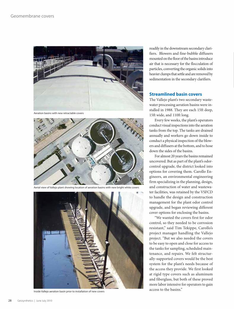
Streamlined basin coversThe Vallejo plant’s two secondary waste-
water processing aeration basins were in-
stalled in 1988. They are each 15ft deep,
15ft wide, and 110ft long.
Every few weeks, the plant’s operators
conduct visual inspections into the aeration
tanks from the top. The tanks are drained
annually and workers go down inside to
conduct a physical inspection of the blow-
ers and diffusers at the bottom, and to hose
down the sides of the basins.
For almost 20 years the basins remained
uncovered. But as part of the plant’s odor-
control upgrade, the district looked into
options for covering them. Carollo En-
gineers, an environmental engineering
firm specializing in the planning, design,
and construction of water and wastewa-
ter facilities, was retained by the VSFCD
to handle the design and construction
management for the plant odor control
upgrade, and began reviewing different
cover options for enclosing the basins.
“We wanted the covers first for odor
control, so they needed to be corrosion
resistant,” said Tim Tekippe, Carollo’s
project manager handling the Vallejo
project. “But we also needed the covers
to be easy to open and close for access to
the tanks for sampling, scheduled main-
tenance, and repairs. We felt structur-
ally-supported covers would be the best
system for the plant’s needs because of
the access they provide. We first looked
at rigid type covers such as aluminum
and fiberglass, but both of these proved
more labor intensive for operators to gain
access to the basins.”
Geomembrane covers
Inside Vallejo aeration basin prior to installation of new covers
Aerial view of Vallejo plant showing location of aeration basins with new bright white covers
Aeration basins with new retractable covers
Geo_Search_fp.indd 1 4/22/10 1:20:55 PM0610GS_p12-31.indd 280610GS_p12-31.indd 28 5/27/10 7:11:22 AM5/27/10 7:11:22 AM

Find what you need in seconds.5000+ articles and growing.
www.geosyntheticsmagazine.com
Search Geosynthetics and our other six industry magazines all at once.
Easy. Fast. Informative.
Fabric Architecture Fabric Graphics InTents Marine Fabricator Specialty Fabrics Review Upholstery Journal
It’s all about the
search
Geo_Search_fp.indd 1 4/22/10 1:20:55 PM0610GS_p12-31.indd 290610GS_p12-31.indd 29 5/27/10 7:11:28 AM5/27/10 7:11:28 AM

30 Geosynthetics | June July 2010
even walked on them while they were in
place over the tank, to see how strong and
durable they were. Based on that trip, we
decided to design these retractable covers
into our aeration basins.”
Installation and operationVallejo’s new retractable, structurally-
supported geomembrane cover system
consists of a composite sheet of high-
strength, UV-protected, coated fabric
tensioned across a series of low-profile
aluminum arches that span the tank’s
opening. Intermediate aluminum walk-
ways spanning the tank are used to divide
the fabric cover sections into appropriate
lengths for easy retractability.
The geomembrane cover fabric is a
laminated sheet of 40-mil specialty PVC
(Ethylene Interpolymer Alloy or EIA) that
acts as a gastight barrier to keep the off-
gas from passing through. It incorporates
a specialized weave design that provides
maximum strength-to-weight ratios.
Since this topsheet is exposed to the
sun, it is also equipped with advanced UV
inhibitors. The material can withstand
temperatures to minus 30°F. This cover’s
attributes include: seam strength, puncture
and tear resistance, low thermal expansion
and contraction properties, a wide range
of chemical resistance, high flexibility, and
dimensional stability under high loads and
temperature fluctuations, making it ideal
for wastewater cover applications.
The covers for the Vallejo site’s basins
are gastight, operating under negative
air pressure. A ventilation system draws
air through the tank and underneath the
covers, and pulls along with it the off-
gas from the aeration process. Off-gas
removal piping is connected directly to
the cover system and out to a soil filter
for odor scrubbing.
Although the membrane covers are
gastight, they can be detached and rolled
up along the frame. This gives operators
Geomembrane covers“Along with Carollo, our engineering firm,
we looked at a number of other wastewater
plants and what they were using to cover
their aeration tanks,” said Barry Pomeroy,
director of Operations and Maintenance
at VSFCD. “We went to a water treat-
ment plant in Colorado that was using
retractable, structurally-supported covers
made with a geomembrane fabric. They
looked like they would be very easy to
remove for maintenance, and [we] watched
how easy they were to open and close. We
Geomembrane covers
The new VSFSD cover showing aluminum walkways
Off-gas removal piping connected directly to the geomembrane covers and then out to a soil
filter for odor scrubbing
0610GS_p12-31.indd 300610GS_p12-31.indd 30 5/27/10 7:11:29 AM5/27/10 7:11:29 AM

www.geosyntheticsmagazine.com 31
access to inspect and maintain inter-
nal components of the two basins. The
membrane covers then reattach in a time-
efficient and safe process. Additional
hatches in the intermediate aluminum
walkways allow access by plant operators
without retracting the entire cover.
Attractive option for municipal wastewater and drinking water plants“The expected life of these retractable
covers is about 15 years,” said Tekippe. “And
the cost is very attractive. If a cover [had] to
be replaced, it would be easy to change out
and could be done in minimal time.
“These retractable covers are well-suited
for both municipal wastewater and drink-
ing water plants. We have since specified
them for use in other public water and
wastewater projects,” Tekippe added.
Today, many municipalities are look-
ing for efficient tank cover systems to
contain off-gases, reduce algae growth,
simplify maintenance and repairs, and
cut expenses. Geomembrane covers have
become an increasingly attractive option for
streamlining wastewater plant operations.
Sources and contacts
Geomembrane Technologies Inc., contact Brennan
Sisk; +1 506 452 7304; 1133 Regent Street, Suite 300,
Fredericton, NB, Canada, E3B 3Z2; [email protected];
www.gticovers.com
Carollo Engineers, contact Tim Tekippe, P.E., Vallejo
Project Manager; +1 512 453 5383; 8911 Capital of
Texas Highway, Suite 2200, Austin, TX 78759; ttekippe@
carollo.com; www.carollo.com
Vallejo Sanitation and Flood Control District, contact
Barry Pomeroy, director of Operations and Maintenance;
+1 707 644 8949, ext. 251; 450 Ryder Street, Vallejo, CA
94590; [email protected]; www.vsfcd.com G
Visit our booths at the following shows:StormCon- booth #825, WasteCon- booth #3008 and ASLA- booth #1103.
To learn more about geomembrane solutions from Firestone Specialty Products
800-428-4442 l info@fi restonesp.com l www.fi restonesp.com/ifai7
{ Proud to be Part of the Overall Solution }Innovative projects require innovative products, like
Firestone Geomembranes. The durability and elasticity of our products, even in exposed applications, combined with our expertise,
help ensure the success of even the most demanding projects.
AGRICULTURE APPLICATIONS
RESERVOIRS
AQUACULTUREAPPLICATIONS
GOLF COURSEAND DECORATIVECOMMERCIALAPPLICATIONS
LANDFILL CAPSAND FLOATINGCOVERS
IRRIGATION CANALS
MININGAPPLICATIONS
STORM WATERAPPLICATIONS
{ Many Applications - One Source }
>> For more, search geomembranes at
www.geosyntheticsmagazine.com
0610GS_p12-31.indd 310610GS_p12-31.indd 31 5/27/10 7:11:31 AM5/27/10 7:11:31 AM

Mirafi® RS580i... the integrated difference.
The new Mirafi® RS580i ...It’s like comparing apples to oranges for Roadway R
Modulus. Separation. Confinement. Water flow. Product identification. Superior integration*.
Protective & Outdoor FabricsAerospace CompositesArmour Composites
GeosyntheticsIndustrial FabricsSynthetic Grass
Integration refers to the overall set of described characteristics based on a review of technical specifications for comparable products published by their respective manufacturers. Individual characteristics of these products vary and may meet, exceed, or fall below one or more of the above described individual characteristics.
0610GS_p32-49.indd 320610GS_p32-49.indd 32 5/27/10 7:11:53 AM5/27/10 7:11:53 AM

1.800.685.9990 | mirafi.com
For a demonstration of this product, visit www.mirafi.com*patent pending
For roads, railways, airport runways, haul roads and embankments, Mirafi® RS580i will be the engineer’s choice...period. All others are just...well...apples.
Mirafi® RS580i is the superior geosynthetic product for base reinforcement and subgrade stabilization.
Our game changing new high-strength woven multi-layered geotextile product provides excellent reinforcement strength and base course confinement integrated with high water flow and soil retention capabilities.
Welcome to the new world of Mirafi® RS580i.
y Reinforcement.
Orange wins.
We will leave you seeing orange.
When compared to the leading subgrade stabilization geosynthetics: holds 2x more force with less overall system movement | lower ultimate elongation | 3x water flow | higher particle retention
0610GS_p32-49.indd 330610GS_p32-49.indd 33 5/27/10 7:11:55 AM5/27/10 7:11:55 AM

34 Geosynthetics | June July 2010
Geosynthetics-based underground
stormwater detention system.
0610GS_p32-49.indd 340610GS_p32-49.indd 34 5/27/10 7:11:55 AM5/27/10 7:11:55 AM

www.geosyntheticsmagazine.com 35
Geosynthetic materials play a major role in new underground stormwater detention system
Terry Sheridan is president of GeoStorage
Corp. His career includes four years as a
regional sales engineer with a national
corrugated steel pipe company and 17 years
with a geogrid manufacturing company,
managing environmental projects, before
founding GeoStorage Corp. in 2006;
Photos courtesy of GeoStorage Corp.
By Terence G. Sheridan, P.E.
Introduction
Stormwater management is an ever-increasing expense on
site development projects.
Stormwater detention ponds are designed to protect against
downstream flooding and environmental degradation. The standard
of practice is to ensure that post-development flow from a site does
not exceed the pre-development rate for a given storm event.
Where land is expensive, detention systems are located under-
ground. Traditional underground detention systems are comprised
of pipes, pipe arches, and concrete vaults. A new underground
stormwater detention system has been developed that combines a
number of different civil engineering disciplines.
Geosynthetic materials play a major role in critical components
of this new stormwater detention system.
Traditional stormwater systemsCorrugated metal and plastic pipes are the most common materials
used in underground stormwater detention applications. These flex-
ible pipes transfer stresses to the surrounding soil and rely on ring
compression and soil arching for structural integrity.
Design standards are based on tightly controlled structural
backfill properties and compaction efforts. Given AASHTO and
state DOT gradation requirements, particularly those related to
the fines content (silt and clay), most flexible pipe projects require
imported backfill.
A new systemA new underground stormwater detention system creates a large
storage chamber utilizing geosynthetics, stone, and concrete slabs.
Essentially, a geotextile or geomembrane liner system is installed
within an excavation. Around the perimeter of the excavation, walls
are constructed with geosynthetic reinforcement and open-graded
stone to create a large underground chamber. Inlet and outlet pipes
extend through the perimeter liner system and wall face into the
open chamber.
PROJECT HIGHLIGHTS
Roosevelt Manor
OWNER
City of Camden (N.J.)
Housing Authority
CITY ENGINEER
Remington Vernick Engineers
PROJECT ENGINEER
PS&S Engineers
GENERAL CONTRACTOR
Haines & Kibblehouse Inc.
STORMWATER SYSTEM
GeoStorage Corp.
INSTALLER
CETCO Contracting Services Co.
0610GS_p32-49.indd 350610GS_p32-49.indd 35 5/27/10 7:11:59 AM5/27/10 7:11:59 AM

36 Geosynthetics | June July 2010
Stormwater detention system
A reinforced concrete roof is installed
over the chamber and supported by the
perimeter abutments/walls. Finally, the
liner system is installed over the stone
surface of the perimeter walls before the
cover soil brings the site to grade. On larger
systems, interior reinforced stone piers can
be installed within an expanded chamber
to increase the width and storage capacity
of the system.
Given the application, water forces
are an important consideration. If water
drains from the chamber faster than it
drains from the backfill, the perimeter
walls will experience a rapid drawdown
condition. The use of angular, open-graded
stone eliminates pore pressures and has
the added benefit of increasing storage
capacity with a 40% void ratio.
GRS wallsAs presented in previous issues of
Geosynthetics magazine (see Refer-
ences, page 41), the Federal Highway
Administration (FHWA) has developed
a geosynthetic-reinforced soil (GRS)
integrated bridge system in an effort to
simplify the design and reduce the cost
of basic, single-span bridges.
The abutment walls of these bridge
systems are characterized by tightly spaced
geosynthetic layers where the spacing is
the key design consideration as opposed
Underground stormwater detention system schematic.
Geomembrane installed with nonwoven geotextile for puncture protection.
Underground stormwater detention system with sand fi lter
0610GS_p32-49.indd 360610GS_p32-49.indd 36 5/27/10 7:12:01 AM5/27/10 7:12:01 AM

www.geosyntheticsmagazine.com 37
to long-term design strength. Another
unique feature of the FHWA integrated
bridge system is the placement of the
bridge superstructure directly on top
of the reinforced abutment. While the
elimination of a bearing pad on top of the
bridge substructure might be anathema
to structural engineers, the performance
of full-scale experiments and an ever
increasing number of installations verify
the capacity of the GRS bearing sills.
The bearing walls of geosynthetic-based
underground detention systems function
in the same manner as GRS bridge abut-
ments. The elimination of a bearing curb
along the wall face reduces costs and speeds
construction. The performance of these
detention systems complements the data
and observations of GRS bridge systems.
E X P A N D E D P O L Y S T Y R E N E
Insulfoam, the leader in block-molded EPS, offers InsulFoam GF… an amazingly versatile and lightweight fi ll product that is 100% recyclable. Weighing as little as 1% of other traditional fi ll materials, InsulFoam GF can save you time and money on your next bridge or road project.
For all your Geofoam needs, remember just one name — Insulfoam.
ENGINEERED EPSVersatile - Durable - Recyclable
800.248.5995
InsulFoam®
Insulfoam · 6004 N. Westgate Blvd. Suite 120 · Tacoma, WA 98406 · Fax: 253.383.7100
®
Underground stormwater detention
systems are typically located below parking
lots. Materials that flex or creep can induce
stress in the pavement section, which can
lead to long-term maintenance problems.
It has been observed that the GRS
integrated bridge system eliminates the
“bump” commonly observed on tradi-
tional bridge approaches where the soil
ramp meets the concrete pier. Similarly,
a geosynthetic reinforced stone detention
system provides a uniformly solid founda-
tion for the parking lot.
The face of the chamber wall is
installed utilizing standard “wrap face”
construction with welded wire forms to
enable compaction to the edge. When a
geogrid is used for reinforcement, the
stone and geogrid apertures have to be
The bearing walls of
geosynthetic-based
underground detention
systems function in the
same manner as GRS
bridge abutments.
0610GS_p32-49.indd 370610GS_p32-49.indd 37 5/27/10 7:12:05 AM5/27/10 7:12:05 AM

38 Geosynthetics | June July 2010
Stormwater detention system
sized to ensure no raveling at the face.
Below the bearing sill, smaller stones are
installed and a geotextile wrap is used at
the face.
Liner system Until recently, most stormwater manage-
ment systems incorporated a detention
system that released the contained storm-
water through a controlled outlet with an
overflow weir to handle storms larger than
the design event.
Today, the preferred practice is to
recharge the ground water through perco-
lation where it is feasible. The liner system
can be designed accordingly.
Geomembranes can be installed for de-
tention applications and provide superior
performance where a reusable water supply
is desired. Recharge/retention applications
can utilize geotextile liners.
In these applications the chamber floor is
accessible for inspection and, when needed,
clogged geotextiles can be replaced.
Roof deckThe roof deck, which spans the chamber
and is supported by reinforced stone walls,
is designed to AASHTO HS-20 bridge
standards (Section 3.24.12).
The roof deck is the most expensive
component of the system. Recognizing
that the deck design is the same whether
the chamber is 2ft or 10ft deep, it is clear
that a deeper chamber will increase the
efficiency of the system. The roof deck
can be cast in place or comprised of pre-
cast panels.
The top of the system is fixed by the
elevation of the lowest upstream manhole/
grate. On detention applications the floor
is fixed by the elevation of the downstream
outlet. On recharge applications depth is
limited by the water table or a low perme-
ability soil stratum.
The drainage and grading plan often
dictates that the system be buried. Bur-
ied systems eliminate concerns about the Precast roof deck panels placed directly on geosynthetic-reinforced walls.
Design note: No concrete grade beam required on bearing sill.
Geosynthetic-reinforced stone perimeter walls constructed with geogrids and
compacted open graded stone.
0610GS_p32-49.indd 380610GS_p32-49.indd 38 5/27/10 7:12:07 AM5/27/10 7:12:07 AM

www.geosyntheticsmagazine.com 39
tolerances of precast panels installed flush
with the parking lot surface.
Inspection and maintenanceSite designs focus on limiting erosion
through the use of Best Management
Practices (BMPs).
However, while BMPs will reduce the
suspended solids in stormwater, sediment
will still collect in the detention system. The
large open chamber of the geosynthetic-
based system enables personnel to inspect
and maintain the underground system.
As stormwater regulations become
more stringent and enforcement more
routine, the ability to inspect and remove
sediment from underground detention
systems will become more important.
Stormwater quality Sand filters are a time-proven pollutant
remover.
However, in underground applications
the cost of the concrete vault required to
house the sand filter is expensive. As a
result, new technologies are entering the
marketplace to meet regulatory pollutant
removal requirements. These technolo-
gies include vortex chambers and filter
cartridge systems housed in smaller con-
crete vaults.
The geosynthetic-based detention
system enables the construction of a tra-
ditional sand filter within a chamber. The
water quality volume can be stored in a
geomembrane lined chamber above the
sand filter.
The geosynthetic-based
underground detention
system off ers a cost-
eff ective alternative to
traditional underground
stormwater detention
and retention systems.
0610GS_p32-49.indd 390610GS_p32-49.indd 39 5/27/10 7:12:12 AM5/27/10 7:12:12 AM

40 Geosynthetics | June July 2010
As an option, a Reactive Core Mat®
can be installed above the sand layer to
decrease its thickness and augment con-
taminant removal. Where desired a second
chamber may be lined to create a forebay
that removes sediment upstream of the
sand filter chamber. The performance of
the geosynthetic based system mimics that
of traditional underground sand filters but
at a significant savings.
ConclusionThe geosynthetic-based underground
detention system offers a cost-effective
alternative to traditional underground
stormwater detention and retention sys-
tems. In addition, this new system requires
a smaller footprint.
In the future, as stormwater quality
regulations are enacted the large open
chamber will offer additional benefits.
The chamber allows for easy access, an
important feature for owners and mu-
nicipalities charged with maintaining their
stormwater systems.
The chamber also provides access to the
geotextile filter should it need to be replaced
because of clogging issues. Lastly, the cham-
ber enables the construction of an efficient
underground sand filter where regulations
require stormwater treatment.
The liner, reinforced walls, and con-
crete deck comprising this system are well
established in the civil engineering market.
Ample research exists to support the design
life of the materials and the performance
of the components.
On even the largest projects the geo-
synthetics can be shipped on a single truck.
The open graded stone is available at the
local quarry and the required tonnage
will be less than the structural backfill
required for an equivalent pipe system.
The concrete roof will be shipped from
the local precaster and require a fraction
of the amount of trucks necessary to ship
an equivalent amount of pipe. In addition,
the excavation will be significantly smaller
Stormwater detention system
Completed stormwater system installed with manhole for chamber access.
Large open chamber allows for accessible inspection and maintenance.
Note: No movement/stress in the upper portion of the wall below the bearing sill.
0610GS_p32-49.indd 400610GS_p32-49.indd 40 5/27/10 7:12:13 AM5/27/10 7:12:13 AM

www.geosyntheticsmagazine.com 41
than a pipe system. For developers looking
to build “green,” the geosynthetic option
offers many distinct advantages over tra-
ditional pipe systems.
Innovation allows construction bud-
gets to accomplish more and stormwater
management is a large and growing portion
of site development and transportation
budgets. By piggybacking on the research
and development of existing civil engineer-
ing technologies, this new system allows
property owners and municipalities to save
money on their stormwater detention and
treatment systems.
ReferencesU.S. DOT/Federal Highway Administration, “Building
the bridge of the future with GRS technology,”
Geosynthetics, Vol. 24, No. 4, 2006, pp. 22-23.
Adams. M., “The GRS bridges of Defiance County,”
Geosynthetics, Vol. 26, No. 2, 2008, pp. 14-21.
Adams. M., Schlatter. W., Stabile. T., “Geosynthetic-
reinforced soil integrated bridge system,” EuroGeo4–
the 4th European Geosynthetics Conference,
Edinburgh UK, September 2008, paper number 271.
CARLISLE GEOMEMBRANES FOR AMERICA AND THE WORLD800-479-6832 • P.O. Box 7000 • Carlisle, PA 17013 • Fax: 717-245-7053 • www.carlislegeomembrane.comCarlisle is a trademark of Carlisle. © 2010 Carlisle.
The industry’s only geomembrane designed with Carlisle’s proprietary weathering technology, Carlisle’s GeoPolypro continuesto perform after 20,000 hours of intense U/V exposure. GM-18 testing, conducted by the Geosynthetics Research Institute, is the most stringent test in the industry.
For more information on Carlisle’s GeoMembrane and the new GM-18 standard,
visit www.carlislegeomembrane.com
Carlisle’s GeoPolypro meets the the new GM-18 standard for polypropylene.
Author’s Note: GeoStorage Corp. owns patents (U.S.
#7,473,055 B2 and international) related to the geosyn-
thetic-based underground stormwater detention system
discussed in this article. G
>> For more, search stormwater at
www.geosyntheticsmagazine.com
0610GS_p32-49.indd 410610GS_p32-49.indd 41 5/27/10 7:12:17 AM5/27/10 7:12:17 AM

42 Geosynthetics | June July 2010
FIGURE 1 The MSE wall and sound barrier wall only
several feet away from the apartment building
FIGURE 2 (INSET) Highway, sound barrier wall, MSE
wall, and apartment building
0610GS_p32-49.indd 420610GS_p32-49.indd 42 5/27/10 7:12:19 AM5/27/10 7:12:19 AM
www.geosyntheticsmagazine.com 43
MSE walls support laterally loaded drilled shaft sBy Jie Han, Robert Parsons, Matthew Pierson, and James Brennan
Jie Han is an associate professor in the Department of Civil,
Environmental, and Architectural Engineering at the University of
Kansas and is the coprincipal investigator on this research project.
Robert Parsons is an associate professor in the Department of Civil,
Environmental, and Architectural Engineering at the University of
Kansas and is the principal investigator on this research project.
Matthew Pierson is a Ph.D. candidate in the Department of Civil,
Environmental, and Architectural Engineering at the University of
Kansas and is the graduate research assistant working on this project.
James Brennan is an assistant geotechnical engineer with the Kansas
Department of Transportation and the monitor of this research project.
Photos courtesy of the authors
PROJECT HIGHLIGHTS
SPONSOR
Kansas Department of Transportation
RESEARCHER
Department of Civil, Environmental, and
Architectural Engineering, University of Kansas
DESIGNER
Tensar International Corp.
GEOGRID AND BLOCK SUPPLIERS (DONATION)
Tensar International Corp. and Midwest Block and Brick
MSE AND SHAFT CONSTRUCTION
KDOT Maintenance
ROCK SOCKETS
Great Plains Drilling
TESTING
Applied Foundation Testing, Dan Brown &
Associates, and KDOT geotechnical group
BLOCKS AND GEOGRIDS
Mesa segmental units, Tensar UX uniaxial geogrids, and
Mesa connectors
A new take on sound-barrier walls
Introduction
When residential areas are close to highways, sound bar-
rier walls are often constructed to minimize noise from
traffic on those roads. Under certain circumstances,
mechanically stabilized earth (MSE) walls are used to support the
sound barrier walls.
Figures 1 and 2 show an MSE wall supporting a sound barrier wall
several feet away from an apartment building near the intersection of
Interstate 435 and U.S. Highway 69 in Overland Park, Kan., a suburb
of Kansas City. Due to weather conditions in Kansas, the sound barrier
wall can be subjected to substantial wind load.
The traditional design practice in Kansas has been to use
reinforced concrete shafts with rock sockets isolated from the MSE wall
to support the sound barrier wall as shown in Figure 3 (page 44). The
isolation of the shafts from the MSE wall simplifies the design of the
shafts and the MSE wall.
In this design, the shafts and the MSE wall are designed indepen-
dently without any interaction. Since it is assumed that there is no lateral
support of the shafts from the MSE wall in this design, rock sockets
are necessary to carry the lateral load from the sound barrier and are
installed prior to the MSE wall construction.
Inner and outer casings are placed with a gap as the wall is
constructed. The inner casing is filled with concrete to form the shaft
once the wall construction is completed. This approach is convenient
for simplifying the design, but construction of rock sockets is slow and
costly.
Under this condition, the shafts are designed as cantilever beams,
which require large-diameter shafts to resist the significant bending
moment. The typical diameter of shafts used for this application ranges
from 2.5–4.0ft. The requirement of rock sockets and large-diameter
shafts makes this system very expensive.
An alternative design was proposed by the Kansas Department
of Transportation (KDOT) and the University of Kansas as shown in
Figure 4 (page 44). In this design, the shafts are included in the MSE
mass and seated on the bedrock instead of being keyed into the bedrock
with rock sockets.
Different from the traditional approach, it is expected in the new
design that the geosynthetic-reinforced soil mass provides lateral
0610GS_p32-49.indd 430610GS_p32-49.indd 43 5/27/10 7:12:24 AM5/27/10 7:12:24 AM
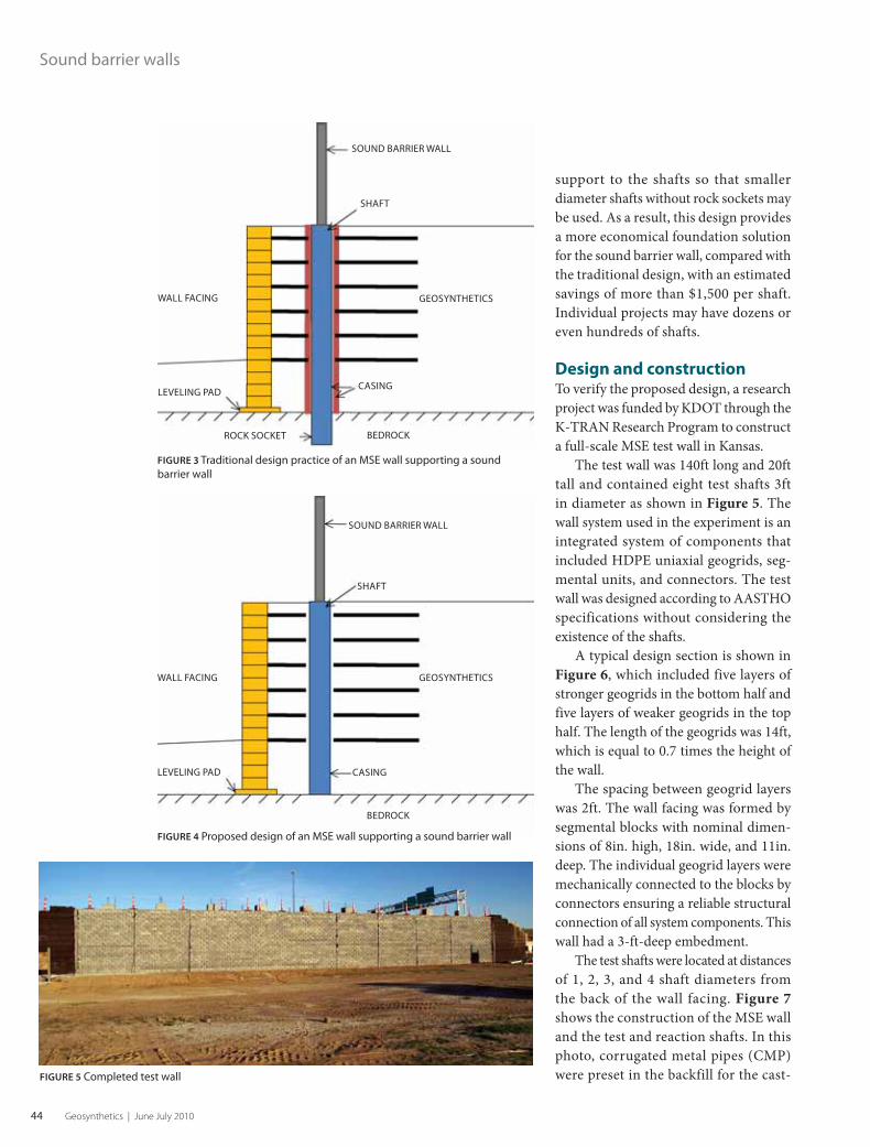
44 Geosynthetics | June July 2010
Sound barrier walls
support to the shafts so that smaller
diameter shafts without rock sockets may
be used. As a result, this design provides
a more economical foundation solution
for the sound barrier wall, compared with
the traditional design, with an estimated
savings of more than $1,500 per shaft.
Individual projects may have dozens or
even hundreds of shafts.
Design and constructionTo verify the proposed design, a research
project was funded by KDOT through the
K-TRAN Research Program to construct
a full-scale MSE test wall in Kansas.
The test wall was 140ft long and 20ft
tall and contained eight test shafts 3ft
in diameter as shown in Figure 5. The
wall system used in the experiment is an
integrated system of components that
included HDPE uniaxial geogrids, seg-
mental units, and connectors. The test
wall was designed according to AASTHO
specifications without considering the
existence of the shafts.
A typical design section is shown in
Figure 6, which included five layers of
stronger geogrids in the bottom half and
five layers of weaker geogrids in the top
half. The length of the geogrids was 14ft,
which is equal to 0.7 times the height of
the wall.
The spacing between geogrid layers
was 2ft. The wall facing was formed by
segmental blocks with nominal dimen-
sions of 8in. high, 18in. wide, and 11in.
deep. The individual geogrid layers were
mechanically connected to the blocks by
connectors ensuring a reliable structural
connection of all system components. This
wall had a 3-ft-deep embedment.
The test shafts were located at distances
of 1, 2, 3, and 4 shaft diameters from
the back of the wall facing. Figure 7
shows the construction of the MSE wall
and the test and reaction shafts. In this
photo, corrugated metal pipes (CMP)
were preset in the backfill for the cast-FIGURE 5 Completed test wall
FIGURE 3 Traditional design practice of an MSE wall supporting a sound
barrier wall
SOUND BARRIER WALL
SHAFT
GEOSYNTHETICS
CASING
BEDROCKROCK SOCKET
LEVELING PAD
WALL FACING
SOUND BARRIER WALL
SHAFT
CASING
BEDROCK
LEVELING PAD
WALL FACING GEOSYNTHETICS
FIGURE 4 Proposed design of an MSE wall supporting a sound barrier wall
0610GS_p32-49.indd 440610GS_p32-49.indd 44 5/27/10 7:12:27 AM5/27/10 7:12:27 AM

www.geosyntheticsmagazine.com 45
ing of shafts after the completion of the
MSE wall.
The casings were installed by staking
short sections of CMP for the shaft
while the backfill and reinforcement
were placed around the CMP. Additional
sections of CMP were added as the fill
progressed and steel cages were placed
inside the CMP. Extruded, punched-
drawn HDPE unaxial geogrid was used
for this test wall and cut to fit around
the shafts as shown in Figure 8.
There was no connection or anchorage
of geogrid to the shafts. In Figure 9, the
test shafts are located in the front row while
the reaction shafts are located in the rear
row, which was behind the reinforced fill.
The test shafts were seated on the bedrock
except one having the length equal to 75%
of the wall height to determine the capacity
of a “short” shaft.
High-quality free draining backfill
material was used for the reinforced and
retained fills. Details on the construction of
this test wall can be found in the research
report by Pierson et al. (2008).
Instrumentation and shaft lateral load testing
This test wall was instrumented with earth
pressure cells behind the wall facing, strain
gages in the geogrid layers, telltales on
the geogrid layers and in the reinforced
fill, inclinometer casings in the test and
reaction shafts and in front of the test
shafts, and targets on the wall facing for
photogrammetry during the shaft lateral
load testing.
Figure 9 shows the test shafts at differ-
ent distances from the wall facing and the
inclinometer casings. These casings were
used during the shaft lateral load testing
to measure the lateral movement of the
shafts and the wall.
Figure 10 (page 46) shows the targets
placed on the wall facing, which were
captured by a high-resolution camera
located at a distance from the wall. The
FIGURE 6 Typical design section
FIGURE 7 Construction of the MSE wall and the test and
reaction shafts
FIGURE 8 Geogrid cut around the shaft casing
FIGURE 9 Test shafts and inclinometer casings
SANDSTONE
LIMESTONE
SHALE
LIMESTONE
0.3m DRAINAGE FILL 0.2m IMPERMEABLE SOIL COVERGRANULAR BACKFILL
14 ft
20 ft1m EMBEDMENT
Profi le of wall and subsurface
0610GS_p32-49.indd 450610GS_p32-49.indd 45 5/27/10 7:12:30 AM5/27/10 7:12:30 AM

46 Geosynthetics | June July 2010
black zone on each target is 6in. long,
which was used as a scale when the image
was imported into the computer-aided
design (CAD) software.
The red frames in Figure 10 show the
original locations of the targets. The green
lines within the red frames indicate the
movement of the wall facing. Details on
the instrumentation can be found in the
paper by Pierson et al. (2009a).
Five single shafts and one group of
three shafts were tested. Figure 11 shows
the setup of the single shaft lateral load
test while Figure 12 shows the setup of
the group shaft lateral load test. Shafts
were pushed toward the wall by one or two
hydraulic jacks and the resulting displace-
ments ranged from 4-9in. Measurements
were taken during each test including the
deflection of the shaft by LVDTs at the
loading elevation and inclinometers, the
movement of the wall facing by the targets,
the internal movement and strains in the
geogrid by telltales and strain gages, and
the earth pressures behind the wall facing
by the pressure cells.
Test results and discussionSignificant amounts of test data were
obtained from this field testing, most of
which are available in the publications by
Pierson (2008) and Pierson et al. (2009b).
Several key results and observations from
the testing are presented here.
Table 1 summarizes the lateral load
capacities of shafts in the MSE wall obtained
from the lateral load testing. Except for Shaft
BS (15ft long), all shafts were 20ft long. Shaft
BG is one of three group shafts. All other
shafts were tested in a single shaft test.
The peak load capacities are reported
at the top displacement of the shaft at
0.5, 0.75, 1.0, 2.0, 4.0in., and an ultimate
state. It is shown that the peak load of each
shaft increased nonlinearly with the top
displacement of the shaft. Lateral capacity
increased substantially with the distance
of the shaft from the wall facing.
Sound barrier walls
FIGURE 10 Targets on the wall facing for photogrammetry
FIGURE 11 Single shaft lateral load test
FIGURE 12 Group shaft lateral load test
TABLE 1 Lateral Load Capacities of Shafts in the MSE Wall (Pierson, 2008)
ShaftDist. from
Facing (in.)Peak Load (kip)
Top Displacement
of Shaft0.5" 0.75” 1" 2" 4" Ultimate
A 36 – 14 15 23 32 34
BS 72 (15' Length) 27 30 33 40 49 55
BG 72 (15' Spacing) 27 35 39 53 70 85
B 72 40 47 50 62 77 90
C 108 39 44 50 66 87 116
D 144 – – 55 81 120 194
0610GS_p32-49.indd 460610GS_p32-49.indd 46 5/27/10 7:12:35 AM5/27/10 7:12:35 AM

www.geosyntheticsmagazine.com 47
Using Shaft D (located close to the
end of the reinforced zone) as a reference,
Shafts A (i.e., the shaft closest to the wall
facing), B, and C had approximately 27%,
91%, and 95% peak load compared with
the reference shaft, respectively, at the
top displacement of 1in. Therefore, the
shaft had a significant load capacity once
the shaft was located at a distance of two
times the diameter of the shaft.
Table 1 shows that the short shaft (Shaft
BS) had more than 60% load capacity as the
regular single shaft (Shaft B) at the same
distance to the wall facing. Table 1 also
shows that the center shaft (Shaft BG) in
the group had 68-94% load capacity as the
regular single shaft (Shaft B), which indi-
cates a group effect for the shafts spaced
at 15ft apart.
After the group load test was per-
formed, a section was excavated to
examine the geogrid between two shafts.
The aperture size of the geogrid was mea-
sured to determine its elongation. The
maximum strain in the geogrid was 3%
and occurred at the shaft and the strain
level decreased to 0 at a distance of 57in.
from the near edge of the shaft. This result
indicates that the surrounding geogrid
was involved in resisting the lateral load
even though the geogrid was cut to fit
around the shafts.
Due to the pattern of the facing blocks
and the rough masonry appearance of
their surfaces, the aesthetics of the wall
system were only affected slightly by the
wall movement, resulting from the lateral
shaft testing. The deflection of the wall fac-
ing was only seen from the top of the wall
looking down, or from the side looking at
the wall facing parallel. The movements of
individual blocks were visible only upon
close inspection, even for wall displace-
ments in excess of 6in.
Despite the significant loadings
and displacements imposed during the
experiment, the wall system remained
fully intact. The mechanical connections
PLASTIC WELDING
800 694 1472 (Western U.S.)800 635 0384 (North-Central U.S.)888 807 4030 (North-Eastern U.S.)800 241 4628 (South-Eastern U.S.)
888 438 6324 (Canada)
Leister Process TechnologiesSwitzerland / www.leister.com
Leister:The specialistfor perfect weldingof geomembranes.
We’ve been setting the standard.For more than 60 years.
E X P O N E N T I A LE X P O N E N T I A Lp o s s i b i l i t i e s
HIGH-POINT® Architectural Fabrics
800-892-9358www.plastatech.com
800-892-9358Tech 5® Geomembrane
Calendered Films • Weft-Inserted Textile Knits Industrial Membranes • Laminates
Field-Proven Performance
Visit us at Booth #1206at the IFAI Expo
0610GS_p32-49.indd 470610GS_p32-49.indd 47 5/27/10 7:12:38 AM5/27/10 7:12:38 AM
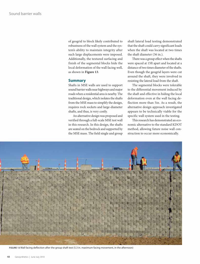
48 Geosynthetics | June July 2010
of geogrid to block likely contributed to
robustness of the wall system and the sys-
tem’s ability to maintain integrity after
such large displacements were imposed.
Additionally, the textured surfacing and
finish of the segmental blocks hide the
local deformation of the wall facing well,
as shown in Figure 13.
SummaryShafts in MSE walls are used to support
sound barrier walls near highways and major
roads when a residential area is nearby. The
traditional design, which isolates the shafts
from the MSE mass to simplify the design,
requires rock sockets and large-diameter
shafts, and thus, is very costly.
An alternative design was proposed and
verified through a full-scale MSE test wall
in this research. In this design, the shafts
are seated on the bedrock and supported by
the MSE mass. The field single and group
Sound barrier walls
shaft lateral load testing demonstrated
that the shaft could carry significant loads
when the shaft was located at two times
the shaft diameter (36 in.).
There was a group effect when the shafts
were spaced at 15ft apart and located at a
distance of two times diameter of the shafts.
Even though the geogrid layers were cut
around the shaft, they were involved in
resisting the lateral load from the shaft.
The segmental blocks were tolerable
to the differential movement induced by
the shaft and effective in hiding the local
deformation even at the wall facing de-
flection more than 5in. As a result, the
alternative design approach investigated
appears to be technically viable for the
specific wall system used in the testing.
This research has demonstrated an eco-
nomic alternative to the standard KDOT
method, allowing future noise wall con-
struction to occur more economically.
FIGURE 13 Wall facing deflection after the group shaft test (5.3 in. maximum facing movement, in the afternoon)
0610GS_p32-49.indd 480610GS_p32-49.indd 48 5/27/10 7:12:39 AM5/27/10 7:12:39 AM

www.geosyntheticsmagazine.com 49
AcknowledgementsThis research project was financially sponsored by the
Kansas Department of Transportation.
The KDOT maintenance and geotechnical group
provided its great help in constructing and testing
the wall.
The contributions of Tensar International Corp.,
Midwest Block and Brick, Applied Foundation Testing,
Great Plains Drilling, and Dan Brown & Associates
were essential to the successful completion of this
project. Their sponsorships and contributions are
greatly appreciated.
ReferencesPierson, M. C., Parsons, R. L., Han, J., Brennan, J. J.,
and Vulova, C. (2009a). “Instrumentation of MSE wall
containing laterally loaded drilled shafts.” Proceedings
of IFCEE 09, ASCE Geotechnical Special Publication No.
187, 353-360.
Pierson, M. C., Parsons, R. L., Han, J., and Brennan,
J. J. (2009b). “Capacities and deflections of laterally
loaded shafts behind an MSE wall.” Journal of the
Transportation Research Board, 2116, 62-69.
Pierson, M. C., Parsons, R. L., Han, J., Brown, D. A., and
Thompson, R. W. (2008). Capacity of Laterally Loaded
Shafts Constructed behind the Face of a Mechanically
stabilized earth Block Wall. Final Report, Kansas
Department of Transportation, 237 pages, www.ksdot.
org/publiclib/publicdoc.asp?ID=003782466. G WE’RE HERE
TO COLLECT…
WAT E R
800.242.WICK PH 704.238.9200 FX 704.296.0690 [email protected] Focusing Our Sites on Gaining Ground
americanwick.com
American Wick Drain provides proven, engineered, highly
cost effective alternatives to pipe and stone
systems. If you are looking for a more efficient way to collect,
transport and redirect water… AWD has the answer. We’re not just
down to earth, we’re… Focusing our Sites on Gaining Ground.
AWD Provides Solutions for:
VERTICAL WALLS
BRIDGE ABUTMENTS
CUT-OFF AND TRENCH DRAINS
RETENTION/DETENTION PONDS
HIGHWAY EDGE DRAINS
LANDSCAPING
PERIMETER DRAINS
CONCRETE CHANNELS
SLOPE DRAINS
TUNNEL AND BOX CULVERTS
CHIMNEY DRAINS
Increased Flow Rates
Reduces Hydrostatic Pressure
Green Friendly
80% Open Area vs. 3-5% with Perforated Pipe
Vertical and Horizontal Applications
The AWD
Advantage
Appleton, Wisconsin, USAPh: 800-548-3424; 1-920-738-1336
The Presto GEOWEB® system...is the ultimate economical and
environmental solution tochallenging slope and
geomembrane protectionproblems.
AP-5993
PRESTO
Original GEOWEB®
Call for FREE Preliminary Design Analysis
>> For more, search walls at
www.geosyntheticsmagazine.com
0610GS_p32-49.indd 490610GS_p32-49.indd 49 5/27/10 7:12:40 AM5/27/10 7:12:40 AM

50 Geosynthetics | June July 2010
GEO NEWS AND NOTES FROM AROUND THE WORLD
PANORAMA
Project HighlightsLocation: Green Point Stadium (“Cape Town Stadium”), Cape Town S.A.Cost: R4.4 billion (approx. USD $600 million)Joint Venture by: Murray & Roberts, WHBOArchitecture: GMP Architects, Louis Karol & Associates, Point ArchitectsGeogrids: Tensar International’s TriAx
Geogrids remedy site soils at World Cup stadium in South AfricaA systematic geogrid installation by South
African World Cup 2010 contractors over-
came poor load-bearing ground encoun-
tered on the new Green Point Stadium in
Cape Town (“Cape Town Stadium”).
Construction of the stadium, which
will play host to a World Cup semifinal
in July, was made problematic by the
highly variable soil inherent to this sce-
nic oceanside setting near the southern
tip of the continent.
The new 68,000-seat stadium was
originally designed set into a deep exca-
vation, to satisfy planning constraints
related to nearby buildings. Initial prob-
lems were encountered as a result of the
excavated material placed uncompacted
over surrounding spaces. So, when tem-
porary, construction haul roads for access
were routed over these areas, considerable
ground movement was experienced.
Because some of these roads would
later become permanent for stadium
access, the routes needed stabilization.
The decision-making became a choice
of removing 6-8m of the fill, replacing
it with properly compacted fill, and
bringing it up to level; or constructing
a mechanically stabilized earth (MSE)
road base with two layers of geogrid
and 400mm of locally-sourced, high-
quality aggregate.
The use of geogrids reduced both
time and cost and this solution was
deemed a success following extensive
use during an exceptionally difficult win-
ter. Even severe rain, including a 58mm
(2.25in.)/hour storm, resulted in mini-
mal settlement or deformation of the
new access road.
These results prompted the contrac-
tors to also utilize localized load-bearing
support for other parts of the stadium:
• Geogrids were installed to reduce
the required thickness of the proposed
aggregate fill in the upper layers of the
“Grand Staircase,” speeding the construc-
tion and saving on imported aggregate.
• At another point of the Grand
Staircase, geogrids were used to rein-
force the bedding under the steps and
reduce any differential settlement that
could compromise the structure and
require remediation.
• Finally, a geogrid mechanically
stabilized layer was installed beneath the
capping “jockey slabs” for the concrete
retaining walls, to mitigate any differ-
ential settlement between the slabs and
the fill where the stadium-site landscape
slopes away towards the sea.
Total construction time for the new
stadium was 33 months.
SourceConstruction News Portal, 4-16-2010
Geosynthetics editor, Ron Bygness, also
contributed to this article.
>> View more news at
www.geosyntheticsmagazine.com
0610GS_p50-Cv4.indd 500610GS_p50-Cv4.indd 50 5/27/10 7:13:10 AM5/27/10 7:13:10 AM

www.geosyntheticsmagazine.com 51
ASCE inducts new class of certified geo-professionalsThe American Society of Civil Engineers’
(ASCE) Academy of Geo-Professionals
inducted the newest class of recipients of
the Diplomate in Geotechnical Engineer-
ing (D.GE) certification.
The group of 41 engineers completed
a certification process that includes
graduate coursework, professional
experience, and an oral defense of the
application. The certifications were pre-
sented at a ceremony at the GeoFlorida
conference in West Palm Beach, Fla. on
Feb. 21, 2010.
The Academy of Geo-Professionals
was founded in October 2008 by the
members of ASCE’s Geo-Institute, with
the goal of providing advanced certifica-
tion to geotechnical engineers. The first
certifications were awarded in March
2009, and the number of engineers who
have earned the D.GE now numbers more
than 150.
In congratulating the inductees, Arlan
Rippe, P.E., D.GE, F. ASCE, president of
the Academy of Geo-Professionals said,
“Certification enhances the value of our
careers by demonstrating a commitment
to the elevated standards and improved
practice. It also reassures the public of the
competence of geo-professionals.”
See the complete list of Feb. 2010
D.GE inductees at: http://geosynthetics
magazine.com/articles/042210a.html
SourceASCE
Personnel updates at NAG, CooleyNorth American Green has named Gabe
Weaver to the new position of manager of
engineering and business development.
In a press release this spring, the com-
pany said it “has married innovation with
expertise in the erosion control industry,”
given Weaver’s background as a profes-
sional engineer plus his new master of
business administration (MBA) degree.
It will allow NAG to leverage his apti-
tude in civil engineering and his recently
earned MBA education to full potential,
the release stated.
Prior to his appointment, Weaver was
the manager of new products and tech-
nology development
for NAG for four
years and has been in
the civil engineering
industry for 11 years.
He will continue as
the technical liaison
to industry organiza-
tions such as the Ero-
sion Control Technol-
ogy Council (ECTC)
and the American
Society for Testing
Materials (ASTM).
At t h e C o ol e y
Group, David Shields
has been appointed
business develop-
ment manager for Cooley Engineered
Membranes. His responsibilities will
include identifying and developing new
markets for that division, according to a
company press release.
Citing his extensive background
with the aviation industry and as for-
mer director of business development
for a large specialty coating and lami-
nating organization, Shields has pre-
sented numerous papers at FAA Cabin
Fire Safety conferences, as well as at
TAPPI and Western Michigan Uni-
versity paper conferences. He has also
been published in Adhesives Age maga-
zine, the release stated.
SourcesNorth American Green, Cooley Group
In MemoriumBernard Myles
Editor’s note: Bernard Myles died on
April 25, 2010. The next day, Sam Allen
of TRI sent this note.
It is with a very heavy heart that I have
to tell you that Bernard Myles died last
night (4/25/2010), following his long
and courageous fight against cancer. His
wife Jan, has instructed that cards and
letters may be sent to her address at (Jan
Blackwood, 15 Greystones Drive, Reigate,
RH2 0HA, United Kingdom). Please do
not send e-mails to her.
As most of you know, Bernard’s con-
tributions to geosynthetics test standard-
ization span some 30 years. He had been
active in CEN and ISO leadership for
many years and brought his passion for
test procedures and standardization to
many ASTM Committee D35 meetings.
Bernie was also active in the Inter-
national Geosynthetics Society. He
was a member of the first IGS Council
formed in November 1983 and remained
on the Council until 1992. He was later
re-elected to the Council in 2000 and
remained until 2008.
There was truly only one Bernie.
He was never without confidence in his
spirited opinions and was always a great
sounding board for new and different
ideas. His lessons were numerous, his
passion rarely matched, and his contri-
butions enduring. He will be missed by
all of us.
Our thoughts are with his family at
this difficult time.
Please also see a personal tribute to Bernard
Myles on page 64.
Gabe Weaver
David Shields
0610GS_p50-Cv4.indd 510610GS_p50-Cv4.indd 51 5/27/10 7:13:13 AM5/27/10 7:13:13 AM

52 Geosynthetics | June July 2010
Short Course Announcements
The Geo-Institute of ASCE, the Industrial Fabrics Association
International (IFAI) and the Geosynthetic Materials Association
(GMA), and the North American Geosynthetics Society (NAGS) join
forces to present Geo-Frontiers 2011 at the Sheraton Dallas Hotel.
The conference is conducted under the auspices of the IGS and will
also feature the GRI-24 Conference on March 16.
Geo-Frontiers 2011 will feature full-day short courses on March
13 catering to beginners and advanced attendees. Each short
course off ers participants 8 PDHs.
INFORMATION FOR THE GEO-FRONTIERS 2011 CONFERENCE
GEO-FRONTIERS WATCH
Advanced Principles of Slope
Stability Analysis
INSTRUCTOR: Garry Gregory, Ph.D., P.E.,
D.GE, Adjunct Professor of Civil Engi-
neering, Oklahoma State University
This short course presents advanced
concepts of slope stability analyses,
with focus on exploration and recon-
naissance techniques, soil strength
including shear strength of fully-
softened clays, computer analysis of
soil slopes, and analysis of slopes with
stabilizing inclusions such as drilled
shafts, tiebacks, soil nails, geogrids,
and fi ber-reinforced soil.
Augured Cast-In-Place (ACIP) Piles:
Design, Construction, Load Test,
and Case Studies
INSTRUCTORS: C. Vipulanandan,
University of Houston; Tracy Brettmann,
Berkel & Co.; and Kenneth E. Tand,
Kenneth Tand & Associates
Augured cast-in-place (ACIP) piles, also
known as continuous fl ight auger (CFA),
are increasingly used for supporting
building, bridges, sound barrier walls,
and many other structures around the
world. Auger piles, with their load-
displacement behavior generally falling
between that of a drilled shaft and a
driven pile, need to be designed for
various applications. ACIP piles are
also socketed in rocks. Diff erent design
methods are available to estimate the
ultimate bearing capacity of ACIP piles
based upon in-situ soil properties, unit
skin friction, and unit end bearing.
Various types of ACIP piling systems
are currently in use, and designing and
constructing issues (installation process
and equipment), as well as specifi ca-
tions including the QA/QC procedures,
will be discussed. Load test results from
various geological formations and sev-
eral case studies, including a highway
bridge totally supported on ACIP piles,
will be presented.
For more information: www.geofrontiers11.org
0610GS_p50-Cv4.indd 520610GS_p50-Cv4.indd 52 5/27/10 7:13:14 AM5/27/10 7:13:14 AM

www.geosyntheticsmagazine.com 53
Design and Construction of Bottom
Liner and Cover Systems
INSTRUCTOR: Richard Thiel, President,
Thiel Engineering
This course covers technologies
and materials used to design
and construct bottom liner and cover
systems for containment facilities
such as landfi lls, heap leach pads,
and ponds, including geomembrane
barriers as well as composite barriers
involving CCLs or GCLs. Participants
will be exposed to design principles
that apply to bottom liner and cover
systems including materials selection
and construction issues, leakage
and contaminant transport, lateral
drainage layer design strategies,
anchor trench design, exposed
geomembrane design, slope stability,
ponds, design details, and geoelectric
survey methods.
Geosynthetic Reinforced Soil
INSTRUCTORS: Robert Holtz, Ph.D., P.E.,
Professor Emeritus, University of
Washington; Jonathan Fannin, Ph.D.,
PEng, University of British Columbia
This short course focuses on advanced
treatment of geosynthetics for soil
reinforcement. Applications include
earth retaining structures, bridge
abutments, and fi ll slopes. Four main
topics are covered: material properties
and durability, principles of analysis,
codes of practice in design, and fi eld
performance data.
Instrumentation, Monitoring,
and Condition Assessment of
Foundations & Geo-Structures
INSTRUCTOR: Magued Iskander,
Ph.D., P.E., F.ASCE, Polytechnic
Institute of NYU
This short course offers a
comprehensive introduction to
instrumentation and monitoring
of civil engineering projects
including planning, design of
instrumentation programs, and
performance of commonly used
sensors, data acquisition, signal
conditioning, error analysis,
information management, and case
histories. The session will combine
elements from civil, mechanical,
and electrical engineering together
with some management concepts.
Application of Geophysics to
Geotechnical Problems
INSTRUCTORS: Rick Hoover, PG,
M.ASCE, Dawood Engineering;
Phil Sirles, Zonge Geosciences Inc.
This program will present geophysical
methods, solutions provided by
those methods, and the concepts
necessary to specify the geophysical
survey parameters necessary to meet
the participants’ project objectives.
At the end of the course, attendees
should be able to: defi ne geophysics,
recognize available geophysical
planning resources and references,
be aware of which geophysical
methods will work and under what
settings, understand how diff erent
geophysical methods are used,
appreciate the ASTM-recommended
geophysical applications for given
problems, defi ne general parameters
for specifi c geophysical applications,
and identify the concepts necessary
to request or specify geophysical
services from a geophysicist.
0610GS_p50-Cv4.indd 530610GS_p50-Cv4.indd 53 5/27/10 7:13:14 AM5/27/10 7:13:14 AM

54 Geosynthetics | June July 2010
>>Continued from page 9 >>
Heavy equipmentEditor’s Note: In the February 2009 issue, a retaining walls article included photos with heavy
construction equipment. A reader asked a question about this and an answer is provided by
the wall builder.
To see the original article, search “reinforced wall project” at: www.geosyntheticsmagazine.com.
Comment RE: Heavy equipmentFrom: George S. | Jan. 28, 2010
I have seen these reinforced walls being used a lot in landscaping projects but it’s
amazing to see how this wall can support the heavy equipment surcharge. What
was the amount of live load surcharge considered for the heavy equipment?
ResponseFrom: Nick Jansson, P.E., LEED, AP, Soil Retention Systems Inc.,
Carlsbad, Calif.
Typically, we add no additional surcharge for heavy equipment. [This] wall system
was designed with enough form capacity to be built properly and is often used
for applications beyond landscaping, such as supporting roadways, houses,
hospitals, and schools. To safely support these kinds of applications, we have
developed a system with the ability to build concurrently with grading. (e.g., a
fully loaded Caterpillar 657E scraper with an operating weight of 271,270 lbs). The
live load resulting from construction equipment is accounted for in the system
development design and is not necessary in the structural design.
A young engineer, molasses, and failed sand drainsEditor’s Note: The October 2009 issue included lots of geosynthetics history, including this
article by Bob Koerner. The following comment was received at geosyntheticsmagazine.com.
To see the original article by Bob Koerner, search “molasses” at: www.geosyntheticsmagazine.com.
Comment: “A young engineer, molasses, and failed sand drains”From: Peter Davies, Kaytech South Africa | Nov. 1, 2009
Hi Bob and thank you for a thought-provoking lesson. I am forwarding it to a
number of acquaintances in the geotechnical field in South Africa.
In my younger days (I’m 63 now!), I worked for around 10 years at Frankipile,
and I spent many an hour down pile shafts being taught the dangers of smear
by that doyen of geotechnics in SA, the late Prof. Jere Jennings who studied at
MIT under Karl Terzaghi.
With that background, and the fact the company I now work for manufactures band
drains among other geosynthetics, I think that your belief that smear may have
caused the failure of the sand piles at Wilmington is well-founded. It seems incredible
that a thin layer of smear could cause such a resistance to flow, but it’s quite possible.
Thanks again. This sort of practical experience is invaluable and it is good that
Geosynthetics is bringing it to a wider global audience.
Best Regards. G
Comment on any
article in Geosynthetics at:
www.geosyntheticsmagazine.com
OR
Send a letter to the editor at:
Contact us at www.geosyntheticsmagazine.com
FROM OUR READERS
0610GS_p50-Cv4.indd 540610GS_p50-Cv4.indd 54 5/27/10 7:13:15 AM5/27/10 7:13:15 AM

www.geosyntheticsmagazine.com 55
Andrew Aho
Managing Director
+1 651 225 6907 or
800 636 5042
GMA is dedicated to
our members’ success.
GMA actively identifi es,
assesses, analyzes
and acts upon market
growth opportunities
and issues that aff ect
its member companies.
The activities of
the association are
proactive in nature and
center on fi ve areas:
» Engineering support
» Business
development
» Education
» Government relations
» Geosynthetics
industry recognition
www.gmanow.com
Geosynthetics: The present and perspectives from Mexico
GMA NEWS
GEOSYNTHETIC MATERIALS ASSOCIATION
By Andrew Aho
The Mexican economy has been
battered by both the worldwide
financial crisis and the effects of a steep
downturn in the U.S., Mexico’s largest
trading partner. And if that was not enough,
Mexico’s economy absorbed another blow
last year with its virtual shutdown during
the swine flu pandemic.
A gathering of the geosynthetic
leadership in Mexico City in March set out
to identify how the organization can best
help grow the market for geosynthetics
in Mexico. Granted, GMA Mexico can-
not address all of the problems with the
Mexican economy, but it can take steps
to insure that geosynthetic materials
are not left unnoticed as the Mexican
economy recovers.
GMA Mexico identified two critical
issues needed to ensure growth:
• The development of clear geosynthetic
specifications acceptable for govern-
ment agencies.
• Expansion of geosynthetic materials
education.
Mexico is now experiencing what
many U.S. construction markets have
already experienced: Government speci-
fiers are cautious about using geosynthet-
ics in various applications because the
industry lacks acceptable specifications
(“specs,” in Mexico, are called “norms”
or standards). And furthermore, speci-
fiers lack familiarity with geosynthetic
materials because engineering education
regarding geosynthetics is sparse.
GMA Mexico, under the leadership
of Oscar Couttolenc, has developed a
working group to address the issue of
absence of well-known and well-regarded
specifications. The current specification
templates that this working group is using
are the AASHTO M288 specs that were
developed by GMA and AASHTO for
use in state transportation applications in
the U.S. An objective now for the Mexi-
can working group is to develop consen-
sus specs and then go about marketing
the specs to the federal transportation
agency, the Instituto Meicano del Trans-
pote (IMT).
GMA Mexico has brought geosynthetic
education directly to the engineers
and specifi ers through a series
seminars throughout Mexico.
Geotextile tubes filled with sand work as foundations
and support beds for oil pipes at the Dos Bocas
facilities for Petroleos Mexicanos in Tabasco, Mexico.
0610GS_p50-Cv4.indd 550610GS_p50-Cv4.indd 55 5/27/10 7:13:16 AM5/27/10 7:13:16 AM

56 Geosynthetics | June July 2010
An second working group is address-
ing the lack of geosynthetic education at
the university level and within the existing
engineering community. National Auton-
omous University of Mexico is one of the
largest higher education institutes in the
world with more than 300,000 students
(with 18,000 students enrolled in the engi-
neering department). These students are
targeted for hands-on geosynthetic edu-
cation. The GMA Mexico working group
is writing a workbook that will eventually
become a text for civil engineering stu-
dents and help expose them to geosyn-
thetic materials and applications.
GMA Mexico has brought geosynthetic
education directly to the engineers and
specifiers through a series of one- and
two-day seminars throughout Mexico.
Recently, GMA Mexico, in conjunction
with the IGS Mexico chapter and the Socie-
dad Mexicana De Ingenieria Geotecnica
held the conference Geosynthetics: Present
and Perspectives in Mexico. The three-day
event was held March 10-12 in Mexico
City. The conference featured two short
courses, a day and a half exhibit hall, and
10 technical sessions. A keynote address
was delivered by Dr. Jorge Zornberg.
For more information:
Manufacturers, distributors, fabricators,
installers, or consultants interested in
participating with GMA Mexico can
reach Oscar Couttolenc at gmamexico@
prodigy.net.mx.
geosyntheticsmarket report
The most comprehensive and accurate measure of the
geosynthetic market in the U.S. and Canada.
This report quantifi es the production of:Geotextiles • Geogrids • Drainage Composites • Geomembranes
It also includes a comprehensive Manufacturers Directory.
For information about purchasing this report, contact Andrew Aho at [email protected] or 800 636 5042.
GMA NEWS
0310GEOsubform.indd 1 3/19/10 8:10:12 AM
>> See the full EPA announcement, with links,
regarding the new coal-ash regulations:
http://geosyntheticsmagazine.com/
articles/050410.html
0610GS_p50-Cv4.indd 560610GS_p50-Cv4.indd 56 5/27/10 7:13:18 AM5/27/10 7:13:18 AM

Title (please check):❑ Owner/Corporate executive❑ Chief/Staff Engineer❑ Geotechnical Engineer❑ Civil Engineer❑ Research/Development Professional❑ Other (please specify)_______________
Type of Business (please check):❑ Engineering Firm / Engineer in Private Practice❑ Contractor❑ Geosynthetic Installer❑ Installation/Fabrication Equipment Supplier❑ Geosynthetic Producer/Distributor❑ Other (please specify)_______________
Fax: +1 651-631-9334 Phone: 800-208-6129Mail: IFAI, SDS-12-2108, PO Box 86, Minneapolis, MN 55486-2108Offer ends December 31, 2010. Please allow 4-6 weeks for shipment of fi rst issue. Offer valid for new subscribers only.
Name ___________________________________________________________
Company ________________________________________________________
Address__________________________________________________________
City _____________________________________________________________
State _________________________________________ Zip _______________
Phone ___________________________________________________________
Fax _____________________________________________________________
Email ____________________________________________________________
Please Print.
❑ $99 $59 /2 Years U.S.A.
❑ $129 $69 /2 Years Canada (U.S. funds)
❑ $179 $99 /2 Years Other Int'l (U.S. funds)
2 years for the price of 1
Leading expert information onNew products/innovative applications• Detailed case study analysis• Global industry topics & trends•
Solutions that reinforce the earth
❏ Bill me❏ Check Enclosed $ ___________________❏ Credit Card Payment ❍ Visa ❍ Master Card ❍ Amex ❍ Discover
Card Number ____________________________________________________
Expire Date ______________________________________________________
Card Holder Name _______________________________________________
Signature _________________________________ Date __________________
SSSSSSSSSSSSSSSSSSSSSSSSSSSSSSSSIIIIIIIIIIIIIIIIIIIILLLLLLLLLLLLLLLLLLLLLLLLLLLLVVVVVVVVVVVVVVVVVVVVVVVVVVVVVEEEEEEEEEEEEEEEEEEEEEEEEEERRRRRRRRRRRRRRRRRRRAAAAAAAAAAAAAAAAAAAAAAAAAAAAAAAAAAAAAAAAAAWWWWWWWWWWWWWWWWWWWWWWWWWWWWWWWWWWWWWWAAAAAAAAAAAAAAAAAAAAAAAAAAAAAARRRRRRRRRRRRRRRRRRRRRRDDDDDDDDDDDDDDDDDDDDDD
fffffffffffffoooooooooooooorrrrrrrrrrrrrrrr bbbbbbbbbbbbbeeeeeeeeeeeeeessssssssssssssssstttttttttttttt tttttttttttttteeeeeeeeeeeeccccccccccchhhhhhhhhhhhnnnnnnnnnnnnnnnniiiiiiiiiiiiiiiicccccccccccccccccccaaaaaaaaaaaaalllllllllllll
aaaaaaaaaaaaaaaaaaaaaaaaaarrrrrrrrrrrrrrrttttttttttttttttttiiiiiiiiiiiccccccccccccccclllllllllllleeeeeeeeeeeeeee
0310GEOsubform.indd 1 3/19/10 8:10:12 AM0610GS_p50-Cv4.indd 570610GS_p50-Cv4.indd 57 5/27/10 7:13:25 AM5/27/10 7:13:25 AM

For more information please contact us» Andrew Aho, Managing Director» Phone: +1 651 225 6907 or 800 636 5042 » E-mail: [email protected]» www.gmanow.com
GMA is dedicated to our members’ success.
GMA actively identifi es, assesses, analyzes and acts upon market growth opportunities and issues that aff ect its member companies. Th e activities of the association are proactive in nature and center on fi ve areas:» Engineering support» Business development» Education» Government relations» Geosynthetics industry recognition
Geosynthetic MaterialsAssociation
Is your company serious about thegeosynthetic marketplace?
Become part of the trade association dedicated to the growth of the industry.
Benefit Executive General Distributor
Determine association direction, budget allocation & other voting matters
▲
Meet & develop relationships with federal policy makers
▲
Influence content of state & federal geosynthetics guidance documents
▲
Speak & instruct users about geosynthetics at construction industry events
▲
Represent industry on AASHTO NTPEP product panels
▲
Become an officer of GMA ▲
Participate in GMA Executive Council meetings & network with industry leaders
▲
Complementary banner ad on gmanow.com ▲
Participate in GMA shipping survey & receive survey data (manufacturers only)
▲ ▲
Complementary product chart listing in Geosynthetics Specifier's Guide issue
▲ ▲
Complementary Company Listing on gmanow.com
▲ ▲ ▲
Advertising discounts inGeosynthetics magazine
▲ ▲ ▲
Participate in GMA General Membership meetings & network with industry leaders
▲ ▲ ▲
Receive Industry News Flashes ▲ ▲ ▲
Subscription to Geosynthetics magazine ▲ ▲ ▲
Complementary company listing in Geosynthetics Specifier's Guide issue
▲ ▲ ▲
Geosynthetics conference discounts ▲ ▲ ▲
Receive minutes from ExecutiveCouncil meetings
▲ ▲ ▲
IFAI membership ▲ ▲ ▲
0610GS_p50-Cv4.indd 580610GS_p50-Cv4.indd 58 5/27/10 7:13:26 AM5/27/10 7:13:26 AM

www.geosyntheticsmagazine.com 59
GSI NEWS
Bob Koerner, Ph.D., P.E.,
NAE, is director of the
Geosynthetic Institute
in Folsom, Pa., and is a
member of Geosynthetics
magazine’s Editorial
Advisory Committee.
GSI: +1 610 522 8440,
www.geosynthetic-institute.org
Lab ImmersionD5323
Field ImmersionD5496
Test Procedure to Evaluate
GeomembranesD5747
GeogridsD6213
GeotextilesD6389
GeonetsD6388
Geopipe(See Comm. F-19)
ASTM Sequence of Standards to
Evaluate Chemical Compatibility
of Geosynthetics to Liquids
(i.e., the alternative to EPA 9090)
Purging the geosynthetics system of dated test methods and specs
GSI’s Mission is to
develop and transfer
knowledge, assess and
critique geosynthetics,
and provide services
to the member
organizations.
GEOSYNTHETICINSTITUTE
By Bob Koerner
In May 1998, Maryann Gorman wrote a
commentary in ASTM Standardization
News entitled “How Specifications
Live Forever.”
She began the article by explaining
how standard gauge railroad track spacing
in North America is 4ft-8.5in. (1.4351m).
It seems that this precise dimension dates
from Roman times because “the Impe-
rial chariots were made to be just wide
enough to accommodate the back-ends
of two war horses.”
From a geosynthetics perspective, let’s
work between agencies (ASTM and EPA)
in that there is currently a series of ASTM
standards that are intended to replace
the EPA 9090 method for determining
chemical compatibility of geomembranes
to various candidate liquids. In fact, more
than 15 years ago, Bob Landreth (long
retired from EPA) requested that we
develop an alternative standard since
EPA was not in the standards setting and
distribution business.
The current series of incubation
practices and subsequent test methods
follows. It is comprehensive and much
more than the original approach. Let us
all use this sequence of ASTM standards
and please stop requesting EPA 9090.
In a somewhat similar vein of
between agency test methods, the Fed-
eral Test Method 101C for evaluating
puncture resistance of geomembranes
is another antiquated test method. The
closest ASTM replacement is D4833
which uses a beveled 5/16-in. (7.94-mm)
probe instead of a tapered point. This
was intentionally done since the tapered
FTM point underestimates scrim rein-
forced geomembranes by having the
probe simply sliding between sets of
adjacent yarns. To our knowledge, cur-
rent geomembrane specifications all use
ASTM D4833. Let’s stop with the FTM
101C requirement.
Completely within ASTM Committee
D35 on Geosynthetics, there are many
meaningful test method changes that the
industry either does not know about or
is reluctant to adopt. Some of them are
as follows:
The old geomembrane ply adhesion
tests (D413 and F904) have been upgraded
and replaced by D7005.
0610GS_p50-Cv4.indd 590610GS_p50-Cv4.indd 59 5/27/10 7:13:28 AM5/27/10 7:13:28 AM

60 Geosynthetics | June July 2010
GSI NEWS
The old geomembrane dogbone tension
test (D638) has been upgraded and replaced
by D6693.
The very old HDPE geomembrane
stress crack test of D1693 has been com-
pletely replaced by D5397.
The old shear and peel tests of
geomembrane seams (D4437 and D4545)
have been replaced by D6214 (for PVC)
and D6392 (for olefins).
The coated fabric test methods
embodied in D751 are completely passé
as is D3088 for PVC.
Regarding laboratory weathering
devices for geosynthetics, the industry’s
current choice is either the Xenon Arc
(ASTM D4355) or the Ultraviolet Fluo-
rescent (ASTM D7238). Following is a
comparison table of approximate initial
and maintenance costs of these contrast-
ing incubation devices. In determining
Cost Comparison Between Laboratory Weathering Devices
ITEM XENON ARC UV-FLUORESCENT
Initial cost $70,000-$80,000 $10,000-$15,000
Tubes/bulbs $15,000/year $300/year
Power cost $5,000/year $400/year
Water cost $3,000/year none
Sewer cost $500/year none
end-of-life testing, the choice is obvious
to us. That said, the entrenched status
of the Xenon Arc method is difficult to
purge from user specifications.
Picking on specifications rather
than test methods, we cannot neglect
commentary on NSF #54. This series of
specifications for 16 different geomem-
branes began in ca. 1980 and was last
published in 1995 by the National Sanita-
tion Foundation, now NSF International.
Shortly thereafter they simply stopped
all geomembrane specification activ-
ity, including distribution of the docu-
ment itself. Even further, some of the
geomembranes addressed in NSF #54
are not available and many others have
been developed and are commercially
available. Yet, we continue to see refer-
ence made to NSF #54 Specifications. It is
time to stop using NSF #54 because there
are viable generic specifications available
for use for the majority of commercially
available geomembranes.
We are sure you have some “golden
oldies” of your own, but thought we would
get these several items off of our chests.
Thanks for listening in this regard.
–Bob and George Koerner, GSI
0610GS_p50-Cv4.indd 600610GS_p50-Cv4.indd 60 5/27/10 7:13:30 AM5/27/10 7:13:30 AM

JUNE
4th Geotechnical/Seoul–Ocean Construction & 7th Ground Improvement Techniques
23–25 JUNE | SEOUL, KOREA
The recurring twin international conferences on
geoenvironmental and geotechnical engineering are
scheduled for June 23–25 in Seoul, South Korea.
GT-2010 “Green Ocean Construction” includes top-
ics such as: LEED, natural disaster warnings, waste
management, beach restoration, aquaculture,
desalinization, and others.
GI-2010 “Ground Improvement Techniques” in-
cludes topics such as: soil stabilization and rein-
forcement, compaction of granular soils, grouting,
environmental aspects, and others.
To register or for more information: cipremie@
singnet.com.sg, www.cipremier.com
AUGUST
Earth Retention-2010
1–4 AUGUST | BELLEVUE, WASH.
ER Conference-3 will be at the Hyatt Regency
Bellevue Aug. 1–4.
Organized by the Earth Retaining Structures Com-
mittee of ASCE’s Geo-Institute, the every-20-years
event follows ER-1 (1970) and ER-2 (1990) that were
held in Ithaca, N.Y. ER2010 will bring together a
broad community of geo-professionals working on
retention structures using a wide range of support
systems with comprehensive coverage of develop-
ments during the past 20 years.
Conference coverage is diverse, including case
histories and practice-oriented papers, recent
research findings, innovative technologies, and the
emerging arts across many disciplines. Professional
engineers, researchers, specialty contractors, regu-
lators, educators, and students will interact across a
range of technical sessions, tutorials, short courses,
discussions, and equipment demonstrations.
For more information: www.er2010.org
StormCon 2010
1–5 AUGUST | SAN ANTONIO, TEXAS
The annual Stormwater Pollution Prevention
Conference is at the JW Marriott Hill Country
Resort & Spa.
The event features an exhibit hall, pre-conference
workshops, nationwide certification courses, and
concurrent technical sessions.
To register, exhibit, or for more information:
http://www.stormcon.com
SEPTEMBER
3rd International Symposium on Geosynthetic Clay Liners
15–16 SEPTEMBER | FORTRESS
MARIENBERG | WÜRZBURG, GERMANY
Topics for this conference include: application/
case studies, durability/lifetime, laboratory test-
ing, performance, and regulations/approvals.
The Scientific Committee: Robert M. Koerner (GSI),
Nathalie Touze-Foltz (Cemagref ), and Helmut
Zanzinger (SKZ).
The Organizing Committee: Irina Bender (SKZ)
and Norbert Schlör (SKZ).
For more information:
www.gbrc-wuerzburg.com
ASDSO’s Dam Safety ‘10
19–23 SEPTEMBER | SEATTLE
The conference, associated meetings, and tech-
nical sessions will be at the Washington State
Convention Center in downtown Seattle.
Hotel reservations in the ASDSO group block are
available until Aug. 24 at the Grand Hyatt Seattle
(www.grandseattle.hyatt.com) or the Hyatt-Olive
8 (www.olive8.hyatt.com). Or call the Passkey
reservation service (888 421 1442) to make a
reservation at either hotel.
Registration information is now available.
For more information: www.damsafety.org
RemTech Expo 2010
21–23 SEPTEMBER | FERRARA, ITALY
The 4th edition of Remediation Technologies
Exhibition will be held at the Ferrara Exhibition
and Conference Centre in Ferrara, Italy. The event
is organized by the Ferrara Fiere Congress and by
coordinator, Dr. Daniele Cazzuffi.
The RemTech expo will feature: remediation tech-
nologies; removal and encapsulation of asbestos;
characterization, investigation, and instruments for
analysis, inspection, and monitoring; brownfields
and real estate; landfills, and dredging activities.
To register, exhibit, or for more information:
+39 0532 909495 900713, info@
remtechexpo.com, www.remtechexpo.com
OCTOBER
2010 Global Waste Management Symposium
3–6 OCTOBER | SAN ANTONIO
The Global Waste Management Symposium
(GWMS) is a three-day event serving the needs of
the landfill community.
The GWMS offers a technical sessions forum for the
peer-reviewed presentation of applied and funda-
mental research, case studies, and policy analysis.
Among the 2010 GWMS technical session topics:
biocovers, bioreactor case studies, moisture con-
tent in bioreactors, landfill siting issues, landfill
liners and covers, landfill cover performance, final
closure of landfills, leachate management, and
solar energy for landfills.
For more information:
www.wastesymposium.com/gws2010/
public/enter.aspx
Tailings and Mine Waste ‘10
17–20 OCTOBER | VAIL, COLO.
This event is the next in a series of symposia on
mill tailings management started at Colorado
State University in 1978.
The conference objective is to provide a forum
for presenting the state-of-the-art regarding mill
tailings and mine waste, and to discuss current
and future issues facing the mining and environ-
mental communities.
The scope of the conference includes: mill tail-
ings, waste rock, ore, and other mined materials,
containment systems (including geosynthetic
and composite liners, leak detection and collec-
tion systems, and groundwater protection), and
permitting issues.
For more information:
www.tailingsandminewaste.org
IFAI Expo Americas 2010
27–29 OCTOBER | ORLANDO, FLA.
The largest specialty fabrics trade show in the
Americas, the annual IFAI Expo for 2010 is at the
Orange County Convention Center in Orlando.
New for 2010: “Advanced Textiles–Blending Tech-
nology and Materials.”
To register, exhibit, or for more information
on exhibiting, sponsoring, or speaking at the
show: www.ifaiexpo.com
CALENDAR
www.geosyntheticsmagazine.com 61
0610GS_p50-Cv4.indd 610610GS_p50-Cv4.indd 61 5/27/10 7:13:32 AM5/27/10 7:13:32 AM
NOVEMBER
6th International Congress on Environmental Geotechnics (6ICEG)8–12 NOVEMBER | NEW DELHI, INDIA
The Indian Geotechnical Society (IGS) will host
the 6th International Congress on Environmental
Geotechnics (6ICEG) in New Delhi Nov. 8–12, on
behalf of the International Society for Soil Me-
chanics and Geotechnical Engineering (ISSMGE).
More than 400 delegates, including 250 from
abroad, will gather to discuss the latest geotech-
nical developments.
The 6th Congress is titled “Environmental Geo-
technics for Sustainable Development,” with
these eight technical themes: MSWs and landfills;
slurry ponds; contaminated land, groundwa-
ter, and abandoned landfills; geosynthetics and
other new materials; sustainability—professional
practice and education; geohazards—disaster
mitigation and management; testing, monitor-
ing, and performance evaluation; physical and
numerical modeling.
The Congress will have four days of technical
sessions (Monday–Thursday) and one day of field
visits (Friday). The Congress will be held in a five-
star equivalent environment, the India Habitat
Centre in New Delhi.
For more information: www.6iceg.org
Venice 2010: 3rd International Symposium on Energy from Biomass and Waste
8–11 NOVEMBER | VENICE, ITALY
Organized by the not-for-profit International
Waste Working Group (IWWG), this event aims to
provide a platform to encourage integrated and
sustainable waste management and to promote
practical scientific development in the field.
Symposium topics include: potential energy
sources, renewable fuels, anaerobic digestion,
refuse-derived fuel, thermal treatments, policies
and legal aspects, new research and developments.
The event will also include presentations, poster
sessions, a small exhibition, and technical tours.
For more information:
www.venicesymposium.it,
3rd Geosynthetics Middle East9–10 NOVEMBER | ABU DHABI
The theme for this 3rd international conference is
“Waterproofing Systems and Reinforced Structures.”
Conference topics include: polymer/product
development, geopipes, geomembranes,
waterproofing membranes, geotextiles, geogrids,
geocomposites, geocells, clay liners, applications
and case studies,landfills, reservoirs, mining, bridge
abutments, road construction, welding/sealing,
durability, testing, regulations/ standards.
For exhibition and sponsorship opportunities, contact:
Irina Bender, +49-931-4104-436, [email protected].
Venue and accommodations at Le Méridien
Abu Dhabi. Contact: Hisham Ishak, LeMéridien
Abu Dhabi, P.O. Box 46066, UAE; hisham.ishak@
lemeridien.com.
For more information: http://www.skz.de
1st GSI–Asia Conference
16–18 NOVEMBER | TAICHUNG, TAIWAN
This conference will take place at the Windsor
Hotel in Taichung, Taiwan.
The theme is “Geosynthetics in Infrastructure
Applications,” with main topics including: me-
chanically stabilized earth structures, coastal and
hydraulic engineering, erosion control and sus-
tainable engineering, and transportation and
pavement engineering.
To register or for more information: http://
gsi-asia2010npust.edu.tw
Waterproof Membranes–‘10
NOV. 30–DEC. 2 | COLOGNE, GERMANY
The 2010 international business and technology
conference on waterproofing in roofing and
geomembrane liners is at the Maritim Hotel in Co-
logne, organised by Applied Market Information
Ltd. (AMI). The focus is on roofing membranes
and geomembranes.
The opening evening is a welcome cocktail recep-
tion and registration, followed by a two-day pro-
gram of expert presentations. A specialist exhibi-
tion runs concurrently with this conference.
Waterproof Membranes 2010 provides a global
forum for all companies involved in waterproofing
membranes, including end-users, specifiers, archi-
tects, expert installers, manufacturers, researchers,
and suppliers to the industry.
To register, exhibit, or for more information
about this conference, contact Jenny Skinner,
email: [email protected]; +44 117 924 9442.
MARCH
Geo-Frontiers
13–16 MARCH, 2011 | DALLAS
The Geo-Institute of ASCE, the Industrial Fabrics
Association International (IFAI), the Geosynthetic
Materials Association (GMA), the North American
Geosynthetics Society (NAGS), and the Geosyn-
thetic Research Institute join forces to present
Geo-Frontiers/2011 at the Sheraton Dallas Hotel.
Billed as the top geotechnical event of the year, it
reprises a similar event from six years ago—Geo-
Frontiers/2005 in Austin, Texas.
Read more at the Geo-Frontiers Watch section in
this issue, page 52.
To register, exhibit, or for more information:
www.geofrontiers11.com
IFAI Expo Asia
22–25 MARCH, 2011 | SINGAPORE
There is a tremendous output and consumption of
specialty fabrics in the Asia-Pacific region. The cur-
rent trade shows in India and China focus almost
exclusively on the disposable nonwoven industry.
IFAI Expo Asia 2011 is the first major event in
the region that specifically targets end-product
fabricators who use all types of materials: woven,
nonwoven, knit, and composite textiles.
IFAI Expo Asia 2011 will feature a trade exhibition,
attracting three targeted audiences:
• those involved in the supply chain seeking net-
working and partnership opportunities.
• fabricators of finished products in applications
such as medical, automotive, construction, safety,
military, recreation, and structures.
• those who have design, application, and market
influence, such as government purchasing agen-
cies, civil engineers, and architects.
Besides the trade exhibition, the four-day event will
feature world-class educational symposiums for 10
specific niche end-markets for specialty fabrics.
For more information: www.ifaiexpoasia.com
CALENDAR
62 Geosynthetics | June July 2010
0610GS_p50-Cv4.indd 620610GS_p50-Cv4.indd 62 5/27/10 7:13:32 AM5/27/10 7:13:32 AM

www.geosyntheticsmagazine.com 63
The Geosynthetic Materials
Association actively identifies,
assesses, analyzes and acts upon
market growth opportunities
and issue that affect its member
companies. The activities of
the association are proactive in
nature and focus on five areas:
Engineering support • Business
development • Education •
Government relations • Geo-
synthetic industry promotion
VISIT www.gmanow.com
CONTACT Andrew Aho [email protected] 800 636 5042.
The bolded advertisers are
exhibitors at Geo-Frontiers 2011.
Be sure to visit their booths at the
show, which will be held at the
Sheraton Dallas in Dallas, Texas on
13–16 March 2011.
For more information on
Geo-Frontiers 2011, please visit
www.geofrontiers11.com.
SEE US ONLINEwww.geosyntheticsmagazine.com
This magazine is made possible
by the ongoing investment of the
advertisers you see here. We thank
our readers for supporting them
throughout the year.
For advertising rates and
information, call Shelly Arman
at 800 436 2408.
IFAI member
GMA Geosynthetic Materials Association member Tensar Iternational Corporation ✦ GMAThrace-LINQ, Inc. ✦ GMA
ADVERTISER INDEX
41 ACE Geosynthetics ✦ GMA www.geoace.com
Cv2 Agru America ✦ GMA 800 373 2478
www.agruamerica.com
49 American Wick Drain Corp. 800 242 9425
www.americanwick.com
5 Atarfil +34 958 439 200
www.atarfil.com
41 Carlisle SynTec 800 479 6832
www.carlislegeomembrane.com
21 CETCO Lining Technologies ✦ GMA +1 215 357 0630
www.cetco.com
25 DEMTECH Services Inc. 888 324 9353
www.demtech.com
60 East Coast Erosion Blankets 800 582 4005
www.erosionblankets.com
53 Fabinno www.fabinno.com
23 Fiberweb ✦ GMA 800 441 2760
www.TyparGeotextiles.com
31 Firestone Specialty Products ✦ GMA 800 428 4442
www.firestonesp.com/ifai7
Cv3 Geo-Frontiers 2011 www.geofrontiers11.com
56 Geosynthetics Market Report 800 636 5042
58 GMA 800 636 5042
15 GSE Lining Technology Inc. ✦ GMA www.gseworld.com
Cv4 Huesker, Inc. ✦ GMA 800 942 9418
www.huesker.com
37 Insulfoam 800 248 5995
www.insulfoam.com
47 Leister 800 694 1472
www.leister.com
19 Maccaferri Inc. ✦ GMA 800 638 7744
www.maccaferri-usa.com
7 Mekamore 82 31 718 0326
www.mekastone.com
11 NAUE America Inc. ✦ GMA +1 404 504 6295
www.naue.com
47 Plastatech Engineering 800 892 9358
www.plastatech.com
39 Plastika Kritis +302810 3089500
www.plastikakritis.com
49 Presto Products 800 548 3424
www.prestogeo.com
1 Strata Systems Inc. ✦ GMA 800 680 7750
www.geogrid.com
32, 33 TenCate Geosynthetics ✦ GMA 800 685 9990
www.mirafi.com
2 Tensar International Corp ✦ GMA 888 828 5007
www.tensarcorp.com/MESA_GEO
0610GS_p50-Cv4.indd 630610GS_p50-Cv4.indd 63 5/27/10 7:13:32 AM5/27/10 7:13:32 AM

64 Geosynthetics | June July 2010
Bernard Myles was my friendWednesday, April 28, 2010
By Pete Stevenson
GeoFront11SaveDateAd_FP_0310.indd 1 3/18/10 2:59:32 PM
FINAL INSPECTION
Bernard Myles was my friend. We met in 1980 in
New Orleans at an organizing meeting for the IFAI
geotextile committee where he was the only sensible
voice. During the next 30 years he became my friend and
he remained a sensible voice. He was a teacher, a guide, a
mentor, and a critic. Bernard was a scientist, an engineer,
a warrior, and a superb friend. We shared so many
adventures I cannot recount them all, else this note would
become a bore rather than a tribute. We worked together
in the exhibit hall at the 2nd ICG in Las
Vegas and, of course, that was when the
IGS was conceived. I became a mem-
ber of the IGS in Brussels the next year
at Bernard’s insistence and we worked
together in industry and in the IGS
until last year when he became so ill.
Bernard Myles was a founding
member of the IGS and attended the
Paris Conference, the organizing meet-
ing in Las Vegas, and served on the first
council. Bernard served 16 years on
the council and attended so very many
council meetings and conferences.
His dedication to the IGS is unquestioned. He
assumed the role of the guardian of the interests of the
corporate membership, which was a role he played both
as a council member and also during the period he was
not a council member. Bernard was a burr under the sad-
dle, never allowing an issue to be avoided, always requir-
ing that the right thing be done. The IGS is indebted to
Bernard Myles.
Following our meeting in New Orleans a 30-year
chronology must include geotextile tubes in Venice
and high-strength geotextile runway extension follow-
ing Allan Haliburton’s lead at Washington National
(now Reagan) both in 1982–83, which was followed by
high-strength fabrics in U.S., Finland, and around the
world. Over the following years we pursued engineer-
ing, manufacturing, high-strength seams, and unique
solutions that included continuous filament nonwoven
geotextiles in Switzerland, soil nailing in the U.K., Cali-
fornia, and Colorado, and polyester geogrids once again
in the U.S.
Along the way we were team members in the days of
Burlington and ICI, and then he worked for me while at
James River. We were partners in Acme STW and later I
worked for him in Soil Nailing and then he worked for
me at Xtex. Regardless of organization charts, in reality
we were always partners. It was a rich and rewarding
friendship, and one that I would wish for anyone.
Bernard Myles held strong views and expressed them
often and with passion. He never ducked a fight and there
were many occasions in which we did not fully agree and
we had some lively debates.
Our solution was to run and we ran together many
times, in the Apennines, in London, on the Washington
mall, in Paris and Brussels and Milan, and a host of
places I omit, and near our homes as we visited together
innumerable times. Running was special because we
had to concentrate to communicate, breathing being an
impediment to excess wordiness. We did argue a great
deal in restaurants, trains and cars, and cars had a unique
effect. We could become so involved as to lose track of
conditions and on several occasions one of us received a
not-so-friendly instruction to pay more attention from
local law enforcement.
In between arguments on politics, technology,
strategy, and nonsense we wrote a business plan while
snowbound in the Alps, lived on the economy in
Singapore during the conference there, shot steel rods into
the earth in Oregon, and generally had a great time.
Bernard was my best man. Bernard’s children, Doris
and Philip, spent time at my home and my son Michael
spent a summer under Bernard’s watchful eye in a test-
ing lab in the U.K. My youngest, Tara, visited Sweden
in the summer with Bernard’s family.
We were three weeks different in age, I the elder … I
miss him now and I will miss him forever. I am so sorry to
say goodbye. For me, the world is a lesser place today.
He was more than my friend, he was my brother.
Bernard Myles
Pete Stevenson
0610GS_p50-Cv4.indd 640610GS_p50-Cv4.indd 64 5/27/10 7:13:33 AM5/27/10 7:13:33 AM

Where engineering design and construction cometogether with dynamic products and applications
Advances in Geotechnical Engineering
www.geofrontiers11.com
Th e objective of the Event is to share new developments in
geotechnical engineering technologies. Attendees will be
exposed to the latest state-of-the-art-and-practice as applied
to geotechnical engineering.
MARK YOUR CALENDAR
FOR THE GEOTECHNICAL
EVENT OF 2011
Under the auspices ofGeo-Frontiers 2011 is co-organized by Includes GRI-24 Annual Conference
GeoFront11SaveDateAd_FP_0310.indd 1 3/18/10 2:59:32 PM
0610GS_p50-Cv4.indd Cv30610GS_p50-Cv4.indd Cv3 5/27/10 7:13:38 AM5/27/10 7:13:38 AM

Huesker’s eco-friendly Geosynthetics fit nicelyunder our corporate umbrella.
800.942.9418 huesker.com 704.588.5500
Engineering with Geosynthetics
Huesker’s ISO 9001 certified line of quality eco-
friendly Geosynthetics are known for strength and
long-lasting durability. That’s important to you and the
planet because today’s designs call for reinforcement
products that ensure your project will endure well
into the future. It’s good to know when you’re trying
to keep costs from raining down on your project.
Applications for Embankments Walls Slopes Airport Runways
Canal Liners Landfill Capping Systems Encased Columns
Mining Roadways Railroads Levees
Geogrids Geotextiles Geocomposites
0610GS_p50-Cv4.indd Cv40610GS_p50-Cv4.indd Cv4 5/27/10 7:13:39 AM5/27/10 7:13:39 AM