UNCONVENTIONAL MACHINING PROCESS UNIT 1...
57
UNCONVENTIONAL MACHINING PROCESS – UNIT 1 INTRODUCTION Prepared by S. SENTHIL KUMAR AP / MECH SVCET
Transcript of UNCONVENTIONAL MACHINING PROCESS UNIT 1...
UNCONVENTIONAL MACHINING PROCESS – UNIT 1
INTRODUCTION
Prepared byS. SENTHIL KUMAR
AP / MECHSVCET

INTRODUCTION
• Conventional machining process– Metal is removed by means of tool which is harder
than work piece and they both are in contact witheach other
• Demerits of conventional machining process– Disposal and recycling of the chips are difficult and
tedious process
– Large cutting forces are involved in this process

NEED FOR UCM
• Unconventional manufacturing process
– Unconventional machining process
– Unconventional forming process
• Need for unconventional machining process
– Harder and difficult to machine materials, can bemachined easily and precisely
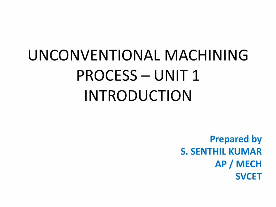
CLASSIFICATION OF UCM
• Classification of UCM– Based on type of energy required to shape the
material• Thermal energy methods• Electrical energy methods• Electro chemical energy methods• Chemical energy methods• Mechanical energy methods
– Based on mechanisms involved• erosion• Ionic dissolution• vaporization
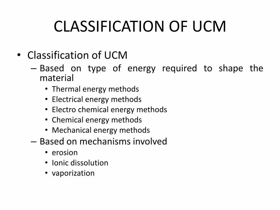
– Based on the source of energy required for materialremoval• Hydrostatic pressure
• High current density
• High voltage
• Ionized material
– Based on medium of transfer of energies• High voltage particles
• Electrolyte
• Electron
• Hot gases

Process Selection
• Points to be considered for correct selection pfUCM are
– Physical parameters
– Shapes to be machined
– Process capability or machining characteristics
– Economic consideration

Physical parameters
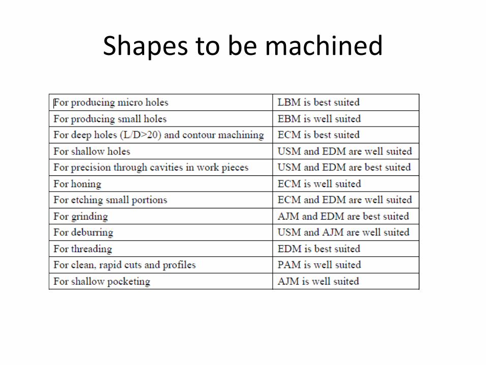
Shapes to be machined
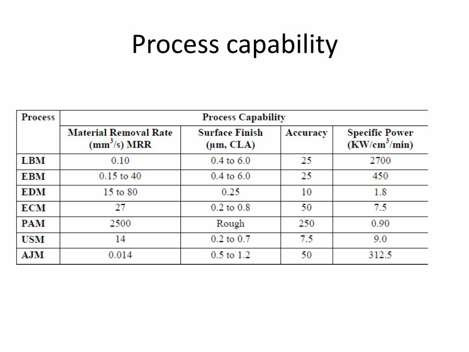
Process capability
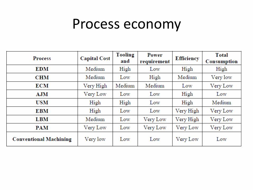
Process economy
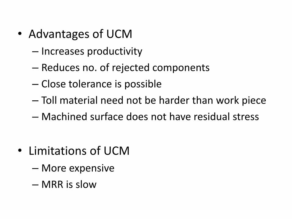
• Advantages of UCM
– Increases productivity
– Reduces no. of rejected components
– Close tolerance is possible
– Toll material need not be harder than work piece
– Machined surface does not have residual stress
• Limitations of UCM
– More expensive
– MRR is slow
UNCONVENTIONAL MACHINING PROCESS – UNIT 2
Mechanical Energy Based process
Prepared byS. SENTHIL KUMAR
AP / MECHSVCET
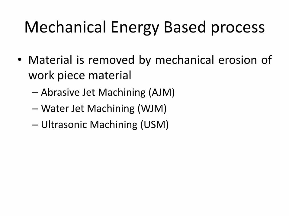
Mechanical Energy Based process
• Material is removed by mechanical erosion ofwork piece material
– Abrasive Jet Machining (AJM)
– Water Jet Machining (WJM)
– Ultrasonic Machining (USM)
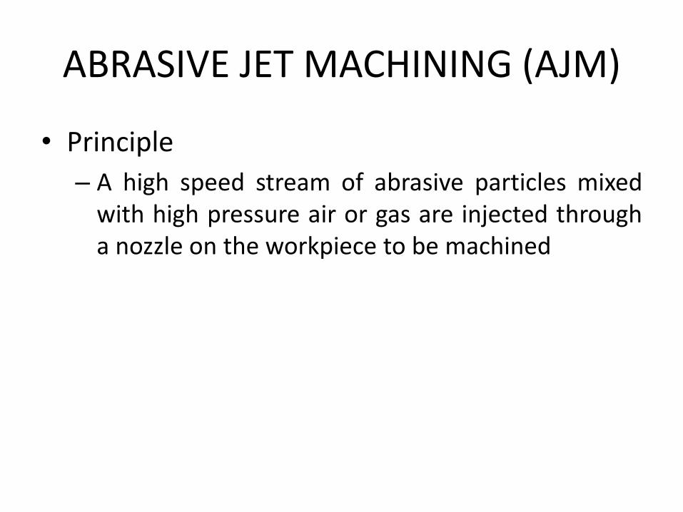
ABRASIVE JET MACHINING (AJM)
• Principle
– A high speed stream of abrasive particles mixedwith high pressure air or gas are injected througha nozzle on the workpiece to be machined
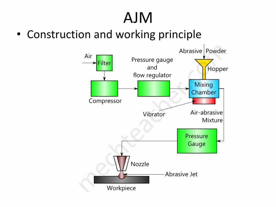
AJM• Construction and working principle

AJM
• Process parameters
– Mass Flow rate
– Abrasive grain size
– Gas pressure
– Velocity of abrasive particles
– Mixing ratio
– Nozzle tip clearance
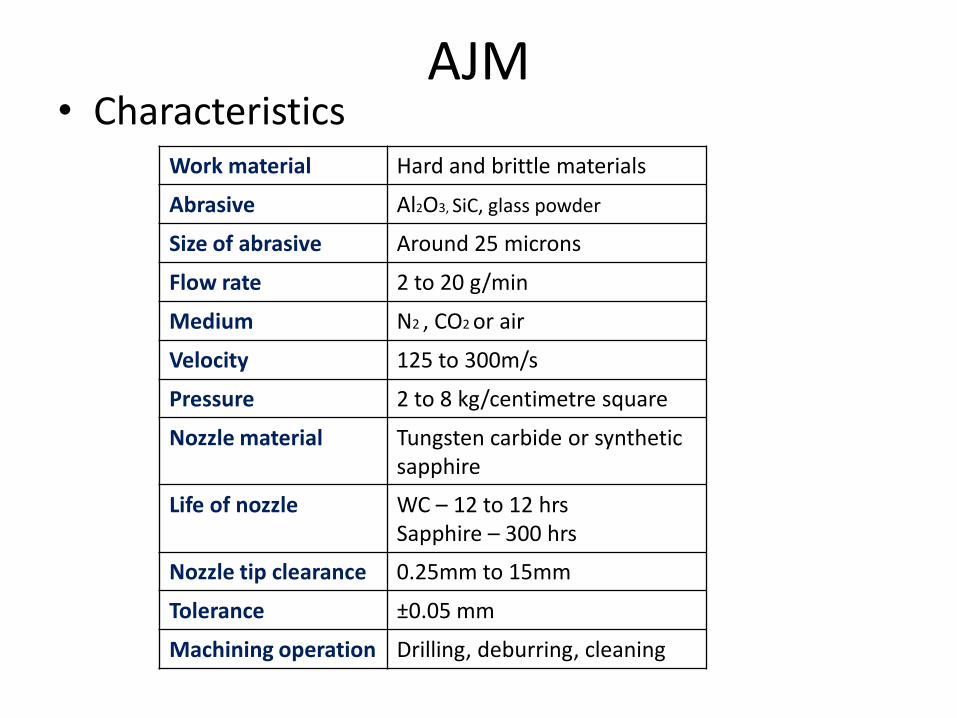
AJM• Characteristics
Work material Hard and brittle materials
Abrasive Al2O3, SiC, glass powder
Size of abrasive Around 25 microns
Flow rate 2 to 20 g/min
Medium N2 , CO2 or air
Velocity 125 to 300m/s
Pressure 2 to 8 kg/centimetre square
Nozzle material Tungsten carbide or synthetic sapphire
Life of nozzle WC – 12 to 12 hrsSapphire – 300 hrs
Nozzle tip clearance 0.25mm to 15mm
Tolerance ±0.05 mm
Machining operation Drilling, deburring, cleaning

AJM
• Applications
– To machine hard and brittle materials
– Fine drilling and micro welding
– Machining of semiconductors
– Machining of intricate profiles
– Surface etching
– Surface preparation
– Cleaning and polishing of plastics, nylon and teflon

AJM
• Advantages
– Process is suitable to cut all materials
– Even diamond can be machined using diamondabrasives
– No direct contact between tool and workpiece
– Low initial investment
– Good surface finish
– Used to cut intricate hole shapes

AJM
• Disadvantages– MRR is slow
– Soft material cannot be machined
– Machining accuracy is poor
– Nozzle wear rate is high
– Abrasive powder once used can never be usedagain
– Requires some kind of dust collection system
– Cleaning is essential after the operation

WATER JET MACHINING (WJM)
• Principle
– When high velocity of water jet comes out of thenozzle and strikes the material, its kinetic energy getsconverted into pressure energy inducing a high stressin the work material. When this stress exceeds theultimate shear stress of the material, small chips ofthe material got loosened and fresh surface is exposed
– Used to cut paper boards, plastics, wood, fibre glass,leather
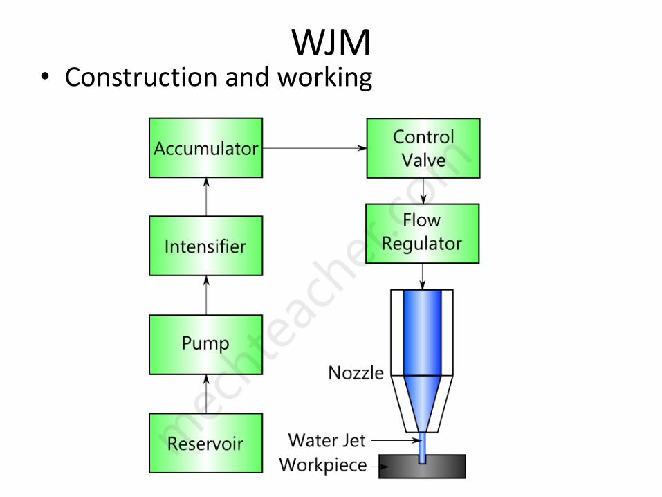
WJM• Construction and working
WJM
• Process parameters– Material removal rate
– Geometry and surface finish of work material
– Wear rate of nozzle
• Disadvantages– Initial cost is high
– Noisy operation
– Difficult to machine hard material

WJM• Characteristics
Work material Soft and non-metallic materials
Tool Water or water with additives
Additives Glycerin, polyethylene oxide
Pressure of water 100 to 1000 Mpa
Mass flow rate 8 lit/min
Power 45 KW
MRR 0.6 Cu.m/S
Feed rate 1 to 4 mm/s
Nozzle material Tungsten Carbide, synthetic sapphire
Stand off distance 2 to 50 mm

WJM
• Advantages
– Water is used as energy medium and hence it ischeap, non-toxic and easy to dispose
– Low operating cost
– Low maintenance cost
– Work area remains clean and dust free
– Easily automated
– No thermal damage to work

ULTRASONIC MACHINING (USM)
• Principle
– A slurry of small abrasive particles are forcedagainst the work piece by means of a vibratingtool and it causes the removal of metal from thework piece in the form of extremely small chips
– Also known as ultrasonic grinding or impactgrinding
– Ultrasonic refers to high frequency – above 20khz

USM
• Construction and working

USM
• Process parameters
– MRR
– Tool material
– Work material
– Surface finish
– Tool wear rate
– Abrasive material & abrasive slurry
USM• Characteristics
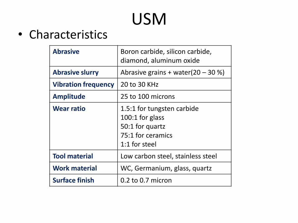
Abrasive Boron carbide, silicon carbide,diamond, aluminum oxide
Abrasive slurry Abrasive grains + water(20 – 30 %)
Vibration frequency 20 to 30 KHz
Amplitude 25 to 100 microns
Wear ratio 1.5:1 for tungsten carbide100:1 for glass50:1 for quartz75:1 for ceramics1:1 for steel
Tool material Low carbon steel, stainless steel
Work material WC, Germanium, glass, quartz
Surface finish 0.2 to 0.7 micron

USM
• Advantages
– Extremely hard and brittle materials can bemachined easily
– Noiseless operation
– Cost of metal removal is low
– No heat generation on this process
– Equipments are safe to operate
– No conductive materials can easily be machined

USM
• Disadvantages
– MRR is slow
– Softer materials are difficult to machine
– Wear rate of tool is high
– Initial setup cost is high
– High power consumption
– Tool cost is high
– Abrasive should be replaced periodically

USM
• Applications
– Holes as small as 0.1 mm can be drilled
– Precise and intricate shaped articles can bemachined
– Efficiently applied to machine glass, ceramics,tungsten
– Used for making tungsten carbide and diamondwire drawing dies and dies for forging andextrusion process

USM• Limitations
– Under ideal conditions• Penetration rate – 5cu.m/min
• Power – 500 to 1000 W
– MRR on brittle materials – 0.18 cu.m/J
– Hole Tolerance – 25 microns
– Surface finish – 0.2 to 0.7 microns
• Recent developments– Instead of using slurry, the tool is impregnated
with diamond dust
– In some cases it is impossible to rotate the tool, sothe work piece will be rotated in some cases

UNCONVENTIONAL MACHINING PROCESS – UNIT 3
Electrical Energy based processes
Prepared byS. SENTHIL KUMAR
AP / MECHSVCET

Electrical Energy based processes
• Electrical energy is directly used to cut thematerial to get the final shape and size
– Electrical discharge machining (EDM)
– Wire cut Electrical Discharge Machining (WC EDM)

Electrical Discharge Machining (EDM)
• Principle
– Metal is removed by producing powerful electricspark discharge between the tool (cathode) andthe work material (anode)
– Also known as Spark erosion machining or electroerosion machining
EDM
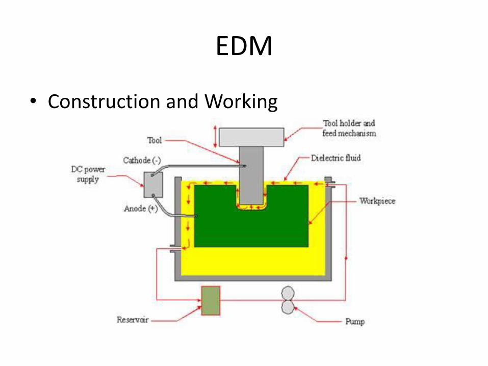
• Construction and Working
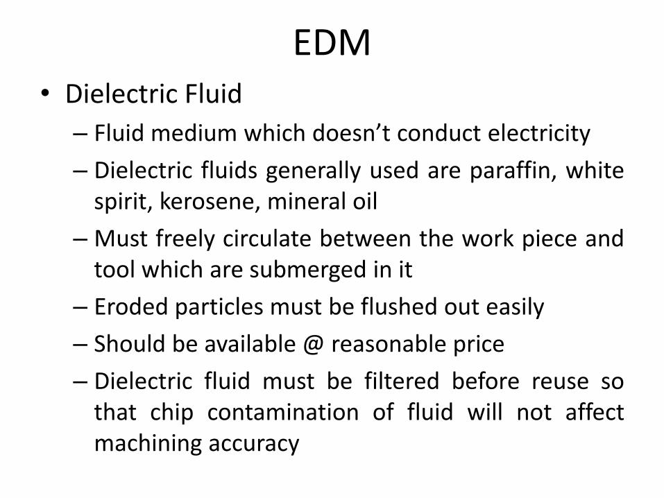
EDM• Dielectric Fluid
– Fluid medium which doesn’t conduct electricity
– Dielectric fluids generally used are paraffin, whitespirit, kerosene, mineral oil
– Must freely circulate between the work piece andtool which are submerged in it
– Eroded particles must be flushed out easily
– Should be available @ reasonable price
– Dielectric fluid must be filtered before reuse sothat chip contamination of fluid will not affectmachining accuracy

EDM
• Functions of dielectric fluid
– Acts as an insulating medium
– Cools the spark region & helps in keeping the tooland work piece cool
– Carries away the eroded material along with it
– Maintains a constant resistance across the gap
– Remains electrically non-conductive

EDM
• Tool materials and tool wear
– Metallic materials
• Copper, Brass, Copper-tungsten
– Non metallic materials
• graphite
– Combination of metallic and non metallic
• Copper – graphite
– Three most commonly used tool materials are
• Copper, graphite, copper-tungsten

EDM• Tool materials
– Graphite• Non-metallic• Can be produced by molding, milling, grinding• Wide range of grades are available for wide applications• It is abrasive and gives better MRR and surface finish• But costlier than copper
– Copper• Second choice for tool material after graphite• Can be produced by casting or machining• Cu tools with very complex features are formed by chemical
etching or electroforming
– Copper-tungsten• Difficult to machine and also has low MRR• Costlier than graphite and copper

EDM• Selection of cutting tool is influenced by
– Size of electrode
– Volume of material to be removed
– Surface finish required
– Tolerance allowable
– Nature of coolant application
• Basic requirement of any tool materials are– It should have low erosion rate
– Should be electrically conductive
– Should have good machinability
– Melting point of tool should be high
– Should have high electron emission

EDM
• Tool wear– Tool does not comes in contact with the work
– So, life of tool is long and less wear takes place
Wear ratio = vol. of work material removed
vol. of electrode consumed
• Tool wear ratio for– Brass electrode is 1:1
– Copper of 2:1
– Copper tungsten is 8:1
– Graphite varies between 5 and 50:1
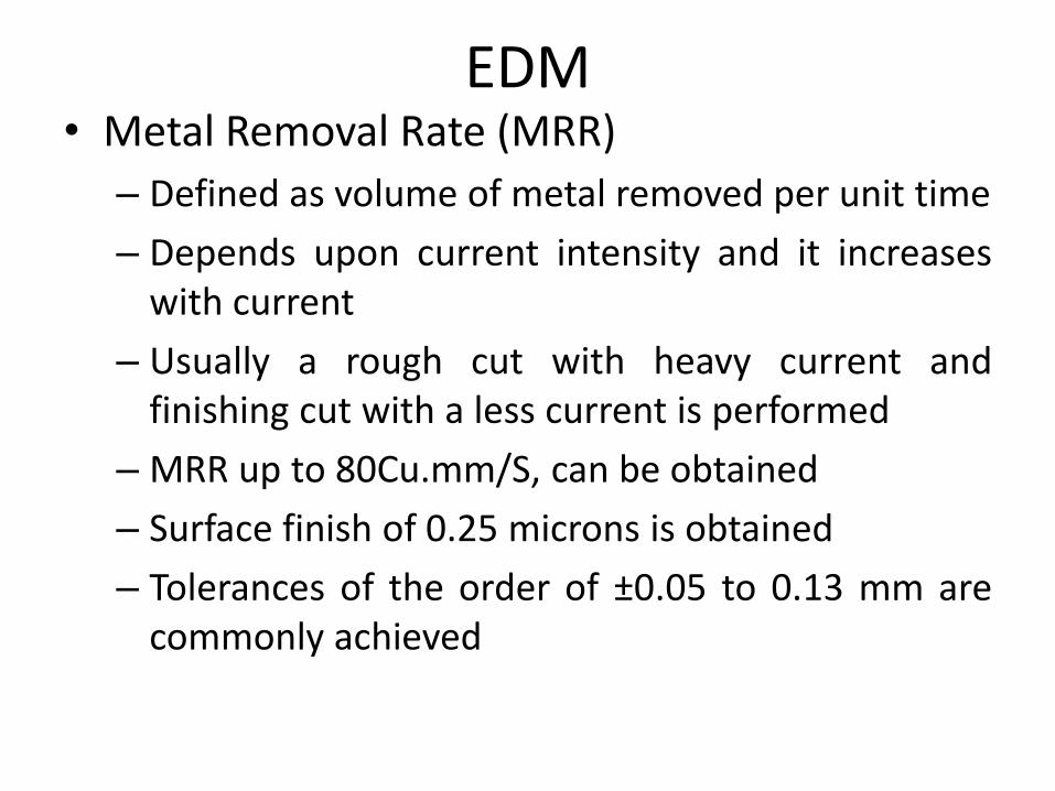
EDM• Metal Removal Rate (MRR)
– Defined as volume of metal removed per unit time
– Depends upon current intensity and it increaseswith current
– Usually a rough cut with heavy current andfinishing cut with a less current is performed
– MRR up to 80Cu.mm/S, can be obtained
– Surface finish of 0.25 microns is obtained
– Tolerances of the order of ±0.05 to 0.13 mm arecommonly achieved
EDM
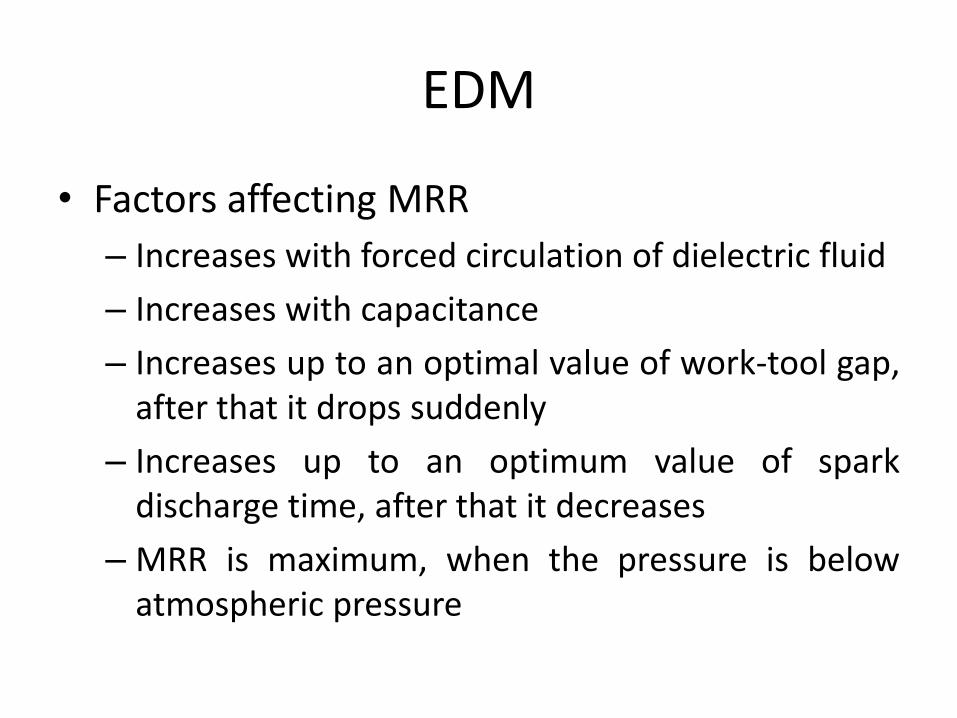
• Factors affecting MRR
– Increases with forced circulation of dielectric fluid
– Increases with capacitance
– Increases up to an optimal value of work-tool gap,after that it drops suddenly
– Increases up to an optimum value of sparkdischarge time, after that it decreases
– MRR is maximum, when the pressure is belowatmospheric pressure
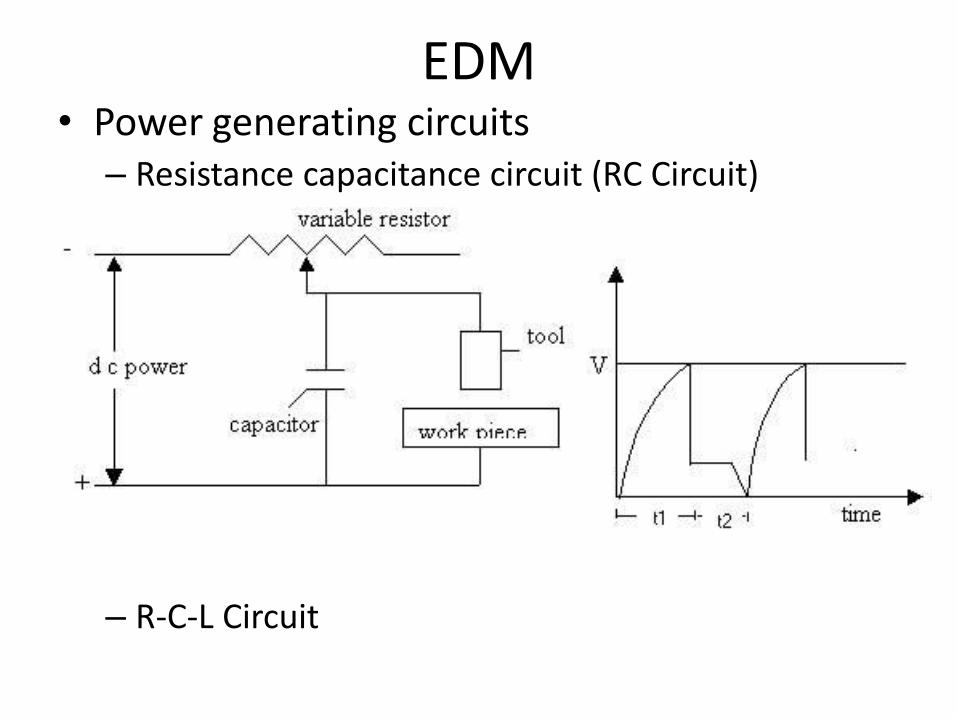
EDM• Power generating circuits
– Resistance capacitance circuit (RC Circuit)
– R-C-L Circuit
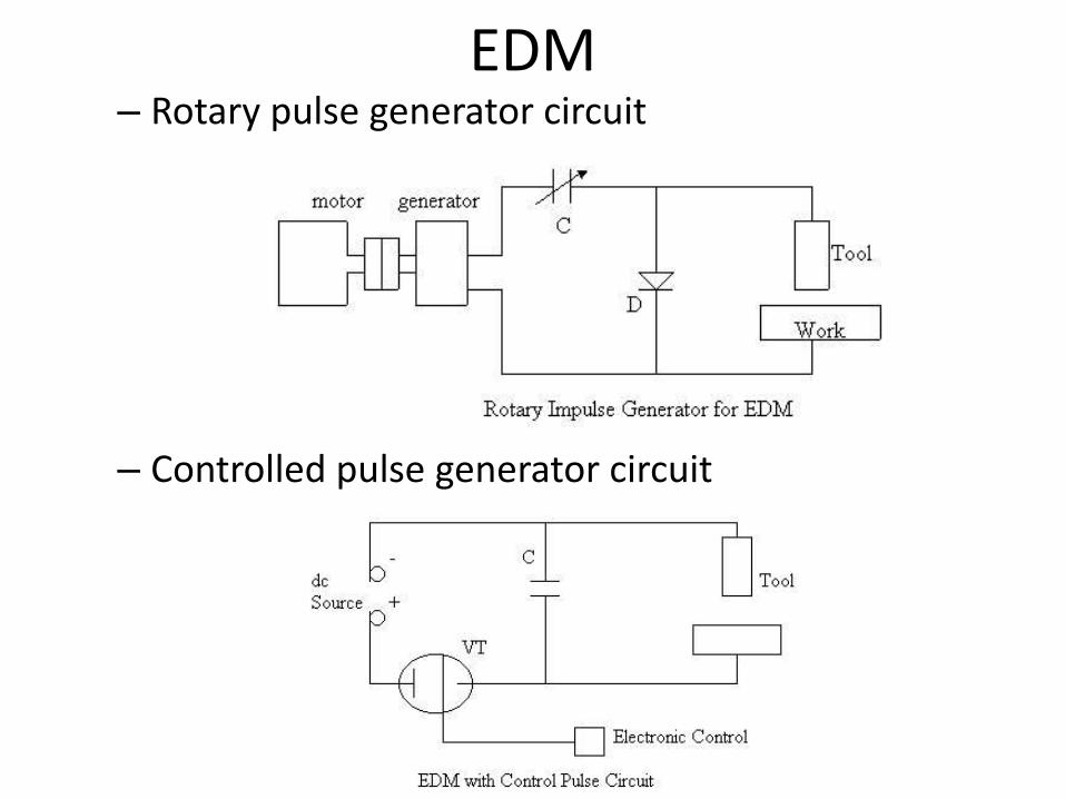
EDM– Rotary pulse generator circuit
– Controlled pulse generator circuit

EDM• Process Parameters
– Operating parameters• Electrical energy
• Voltage
• Time interval
• Instantaneous current
• Torque
• Pulse width
– Taper
– Surface finish• Energy of the pulse
• Frequency of operation
– Current density
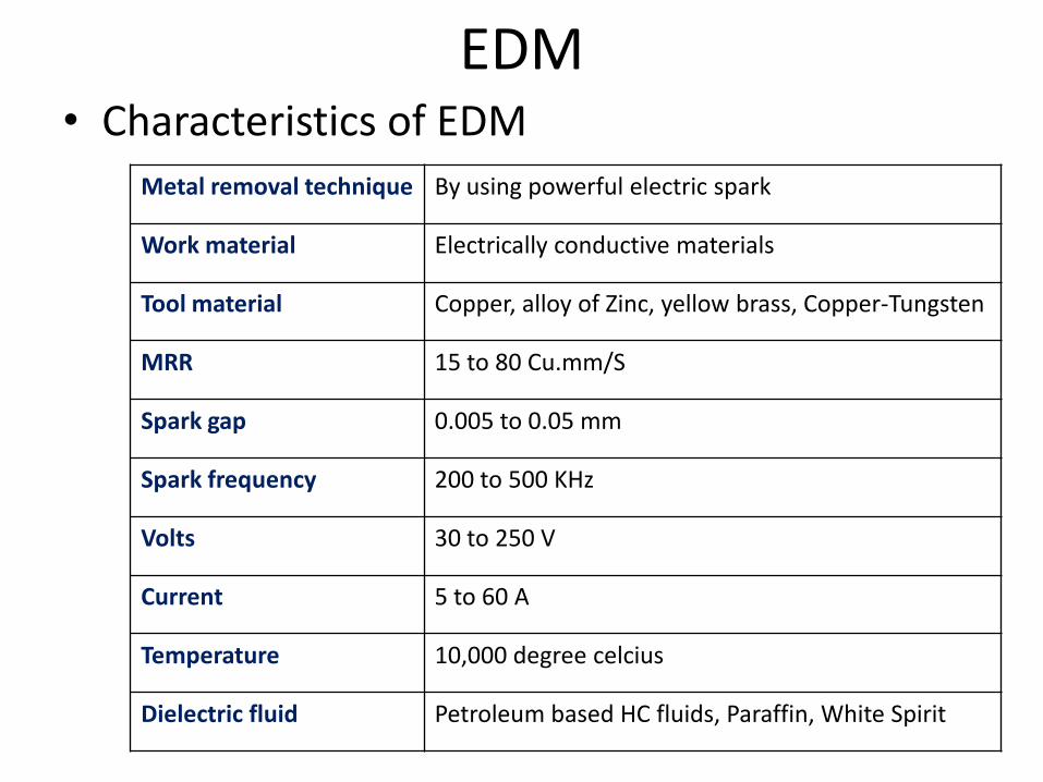
EDM• Characteristics of EDM
Metal removal technique By using powerful electric spark
Work material Electrically conductive materials
Tool material Copper, alloy of Zinc, yellow brass, Copper-Tungsten
MRR 15 to 80 Cu.mm/S
Spark gap 0.005 to 0.05 mm
Spark frequency 200 to 500 KHz
Volts 30 to 250 V
Current 5 to 60 A
Temperature 10,000 degree celcius
Dielectric fluid Petroleum based HC fluids, Paraffin, White Spirit
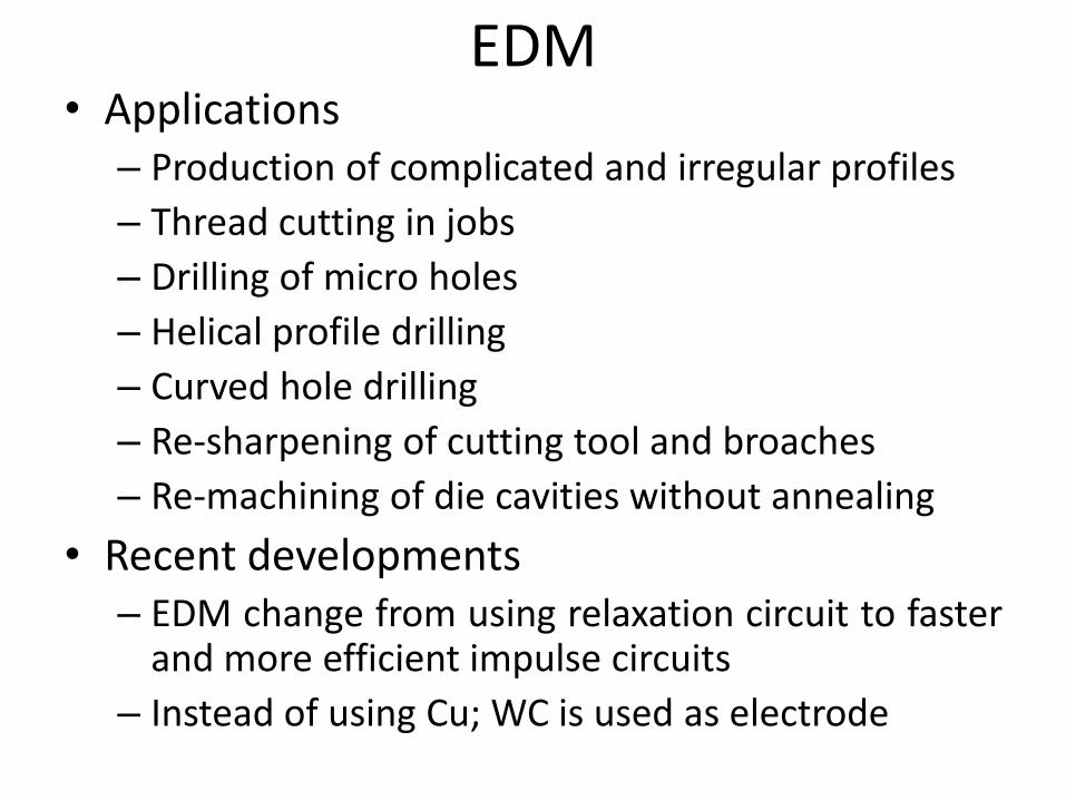
EDM• Applications
– Production of complicated and irregular profiles
– Thread cutting in jobs
– Drilling of micro holes
– Helical profile drilling
– Curved hole drilling
– Re-sharpening of cutting tool and broaches
– Re-machining of die cavities without annealing
• Recent developments– EDM change from using relaxation circuit to faster
and more efficient impulse circuits
– Instead of using Cu; WC is used as electrode
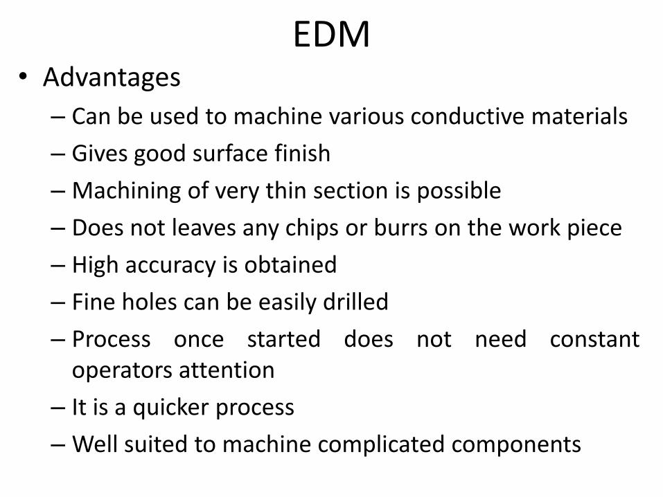
EDM• Advantages
– Can be used to machine various conductive materials
– Gives good surface finish
– Machining of very thin section is possible
– Does not leaves any chips or burrs on the work piece
– High accuracy is obtained
– Fine holes can be easily drilled
– Process once started does not need constantoperators attention
– It is a quicker process
– Well suited to machine complicated components
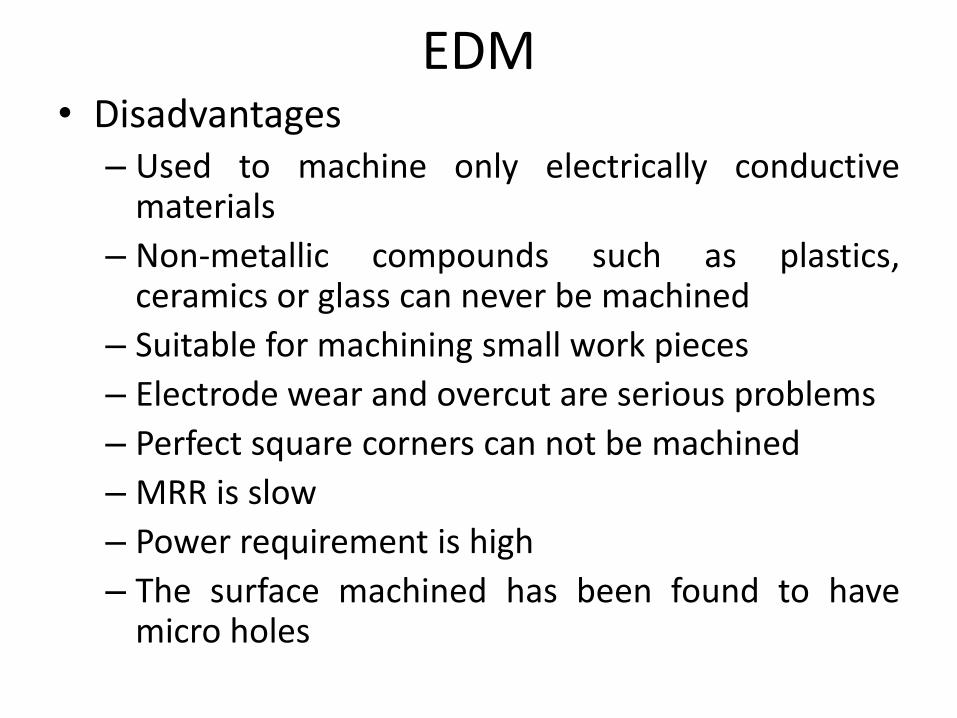
EDM• Disadvantages
– Used to machine only electrically conductivematerials
– Non-metallic compounds such as plastics,ceramics or glass can never be machined
– Suitable for machining small work pieces
– Electrode wear and overcut are serious problems
– Perfect square corners can not be machined
– MRR is slow
– Power requirement is high
– The surface machined has been found to havemicro holes

Wire Cut Electro-Discharge Machining (WC EDM)
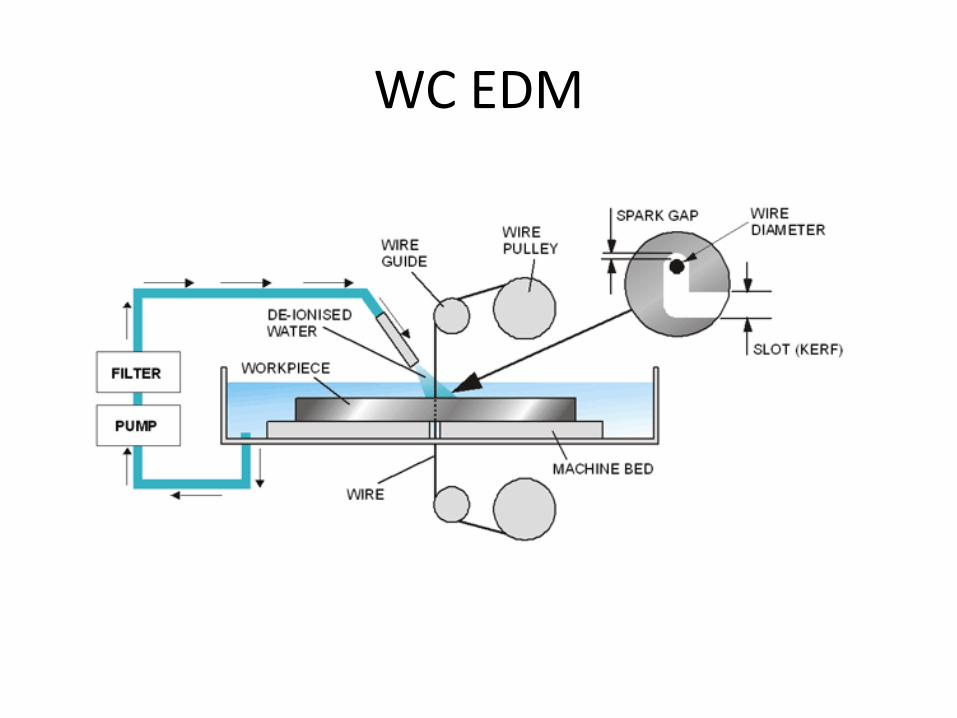
WC EDM

WC EDM
• Applications
– Best suited for production of gears, tools, dies,rotors, turbine blades and cams
• Disadvantages
– Capital cost is high
– Cutting rate is slow
– Not suitable for large work pieces
WC EDM• Features / Advantages of WC EDM
– Manufacturing electrode
– Electrode wear
– Surface finishing
– Complicated shapes
– Time utilization
– Straight holes
– Rejection
– Economical
– Cycle time
– Inspection time

Difference between EDM & WC EDM
S. No
Wire Cut EDM EDM
1 Very thin wire made of brass is used as tool
Expensive alloy of silver and tungsten are used as electrode
2 Whole work piece is not submerged in dielectric medium
Whole work piece is submerged in dielectric medium
3 Easy to machine complex two dimensional profiles
Difficult to cut complex two dimensional profiles