UNCLASSIFIED ----· AD428747 . . DEFENSE ... AD428747 . . ----· DEFENSE DOCUMENTATION CENTER FOR...
34
UNCLASSIFIED . . -- - -· AD428747 DEFENSE DOCUMENTATION CENTER FOR SCIENTIFIC AND TECHNICAL INFORMATION- CAMERON STATION. ALEXANDRIA. VIRGINIA UNCLASSIFIED
Transcript of UNCLASSIFIED ----· AD428747 . . DEFENSE ... AD428747 . . ----· DEFENSE DOCUMENTATION CENTER FOR...

UNCLASSIFIED
. . -- - -·
AD428747
DEFENSE DOCUMENTATION CENTER FOR
SCIENTIFIC AND TECHNICAL INFORMATION-
CAMERON STATION. ALEXANDRIA. VIRGINIA
UNCLASSIFIED

DISCLAIMER NOTICE
THIS DOCUMENT IS BEST QUALITY PRAC!.ICABLE. THE COPY FURNISHED TO OTIC CONTAINED A SIGNIFICANT NUMBER OF PAGES WHICH DO NOT REPRODUCE LEGIBLY.

..
JOriCZ: llwl&Oft~D~Dt or other ~viDa•, apecltlcatlou or ~r data an uaecl tor U7 lNl'»>H
· other tbaD 1D CODDtctlOD vlth a 4et1Dl~ ftlate4 pe=-at ~t opentlon, tM v. s. Ooftmment tllenb;y lncura no reapoulbllit;y, DOr .,~ obUptlon vbat1oever; u4 tbe tact tbat the Oonm·MAt MT Jlave tomalate4, tumllhe4, or 1D ta7 W7 auDUe4 the 1&14 4rav1Dp, apecltlcatlcm., or otMr data 11 DOt to be nprded b71JiplJ.cat!cm or otll6r· Y11e u lD azq -=er 11ceulD& th boldar or U7 other pel'IOD or COI'p)J'&tlon, or conve11Da azq rtpta or pemlallcm to -=tacture, uae or 1ellazq patented lDnDtlOD that -.y lD aJJj ,., be related thereto.

0 ~-. tt ·.
,; .
· ? j'~S' LfO 0 ..:: -
SPR GFIELFY ·ARMORY ·
\
. RESEARCH AND ENGINEERING ~
/ .
INGINUID«: IIWfCH ~ IIOCHUU . J
I ·--- -- ~-.L~~ ~ laalaaer~ Development and Operational Cbaracterlattc• ~
~------=o~f~llfle, 7.6a., H1412 -· ~
18 Deca.ber 1963 •,
....
@J~_; . . . . (;rtt.•t,~--1.. Approved=-~~~---
. l'at • ~1(7 It Y C. UIBU • llecla lq (Orcl) Lt Col• Corpa
lj ,::. ·i
• M&.leA UL.mr.
Chief, lee ancl Ina Div
one c •• - , .r ,-- .. J:'t
1'1 . ~~ l ;: 6EB 'l 1964 ·!: :;
' ~··:: .,,.. .. . . ·-· .. .. ·.- .. ,·· D G 0 t.::. u v t:-: · Tl...... •' . ::>ir. ,.,
ftk!.:mmemx:tz:nca

CONTENTS
Page
I. Iatrocluction 1
A. Scope 1
•• laalneerlng Development 1
c. General Data 5
)). Pbyalcal Cbaracteriatica 5
II. General Deacrlption 6
A. Stock Aaaembly 6
J. Muzzle Stabilizer 6
c. lipod, M2 (Modified) 6
~- SUng, Gun 7
III. Coaveraion of Ml4 Rifle to Ml4 12 lifle 8
IV. A4jljuatment of Sling for. Firing 10
v. Del':alled Description 11
A. Stock 11 '
•• Pront Han~grip Aaa~mbly 11
c. Shoulder 'Reat Assembly 12
D. JtecoU Pad 12
E. Butt Swivel 13
r. Uuzzle Stabilizer 13

I. INTRODUCTION
A. Scope
~!'Ida :tac~ltaLE ie ,..,lbha• •• p:oftw ~urreot -. de1ign characteriatica of Rifle, 7.62mm, Ml4!2.~
1. t;ogioeerly Development of Rifle, 7 .62111D1 Ml\!2
1. Rifle, 7.6~. M14 ~ad Rifle, 7.62Dm, Ml5 were· classified
ataodard on 23 May 1951. The MlS Rifle was the heavy barrel ~del of
the M14 Rifle intended to be used for automatic fire. Test~ by tb~
~1 and the Marine Corps led to the adoption of the Ml4 Rifle ·with the
M2 Blpod and to the obsolescenc~ of the HlS Rifle on 17 Decemb~r 19S9.
2. Tbe Uaer was dissatisfied with the automatic fire ·accu~~cy of
the Ml4 Rifle with the M2 Bipod and, in early 1962, the United States
·Army Infantry Board (USAIB), Fort Benning, Georgia, with the assistance
of the ~y Marksmanahip Unit fabricated and teated a modified Ml4.
Rifle which became known unofficially a1 the Ml4 (USAIB) Rifle.
3. The Ml4 (USAIB) Rifle dem' strated that the automatic fire ac-
curacy requirement~ (i.e., 80 per cent of the shots- mu~t fall within a
40-incb diameter circle at a range of 200 meters when fired in 2- to
3•round bursts) could be met consistently with this configuration. More
M14 (USAIB) Rifles were fabricated and tested extensively.
4. Headquartera, U. S. Army Weapons Co=mand instructed the Ar~ory
on 7 Aus~st 1963 to prepare a technical data package for manuf~cture of
the Ml4 (USAIB) Rifle and to adhere to the original configuration to ~h~
great~st extent practicable. Since there were no drawings or de$i~n
data for the Ml4 (USAIB) Rifle, the Armory an~lyzed the U~AIS and
-1-

,
prepared prel~loary design data and sketches. These aketches and data
provi~d· the basis for the engineering of a comparable desiaa which
would .. et n~t only the operational requirements but also the quantity
,production r~quireaenta. This technical data package was cnmpleted
1 October 1963.
5. On 2 October 1963, Headquarters~ u. s. Army Weapons Coaaalid, in·
atructed the ~~ry to coapletely redesign the front handarip ao that it
would fold to the rear, preaent a small ailhouette in the closed poaition,
and provide greater comfol't when the weapon il carried at sUns anaa.
Tbe.Araory waa instructed that tbia handarf.p should alto be adjua~able
lougitudtoally t~ accommodate the aunner•a ara length. In add~tion, a
butt avlvel ehould be provided which would pivot to the left aide of the
etock to perait aide ellnging of the weapon. The A~ry waa alto re
queated to fabricate four rifle• for confiTmAtlon of design ~4d teatina.
6. · The handgd.p a11eably, 1tock aaaembly, and Ilia& were redeaignecl
and product•euglneered, and four rifles were fabricated and teated by
the ~ry. On.29 October 1963, the deaian was confirmed by h~gher
authority, and four weapons were shipped to the test agencies on 4
Noveaber 1963.
7. The nev weapon waa deaignated Rifle, 7.62mm, Hl4E2 (Photograph
1014).
8. tlated below, are the aignlficant differences between the Ml4
(USAIB) and the Ml4!2 Rifles resulting from r~deatgn to ~eet r~quire
sents and engineering for quantity production.
·2-

. -- ---.----,-- -
c

' a. the atock for the M14 (USAIB) was fabricated from several
placaa of wood cemented toaether to meet the new coDfiguration of the
butt and and the aav rea~ bandarip. ~e front end of the atock wa1
identical vlth the atandard M14 ~ifle except for two hole• to peralt
.,UDtiDa of the front bandarip. The M14E2 atock b fabricated froaa the
standard atock blank except for the rear handarlp which ia doweled and
c~ntad tn place. The front end and the aldea of the atock have been
atreaathened to vitbatand beat and atreasea of automatic fire. Tba
butt ead of the stock aad the rear handgrip have been reshaped to pro
vide areater accuracy and comfort ln firing.
b. 'l'be racoll pad for the Ml4 (USAIB) was of con~~~ercial de·
atan and .. nufactura Which bad to be modified to acco~odate.the
shoulder reat and individually fitted to the atockt. The pad had open
rtbbin& on the aida• Which allowed foreian matter to accumulate, and
tha rubber bad poor ratlatance to oil, abrasion, and cold•cracklng wblch
reaultad in ~ blah replacement factor. Tbe ·:14!2 recoil p-d ia molded
froa rubber with excellent reaiatance to oil, abrasion, and cold·
crackiaa. Thera are no exposed cavitlea to accumulate foreign matter.
The pad baa an integral ateel ahoe for atrength and for tight fit with
the stock; the pad ia interchangeable fro~ ~ifle to rifle.
c. The shoulder rest aasembly for the Ml4 (~SA!R) Rifle ron
listed of the standard Ml4 Rifle shoulder rest plate rr.cuncnd 01 a blor.k
and a atop plate screwed to the top of the block. This ~top pLr.Le
projected above the top and the side surfaces of th~ :otodt.. ;: , .:•:t.!rt
was provided to hold the rest in the open or clcs~<! posf.ti("' ' .':\e
-3-

shoulder rest asse~bly for the Ml4E2 is a co=pletely new design with
only one movins pa~t, the shoulder rest plate. This design provides
detent action for both the open and the closed positions and eliminates
projection• beyond the contour of the stock (Photograph 1166).
d. Tbe muzzle 1tabilizer for the H14 (USAIB) consisted of a
perforated steel aleave welded to the flaah suppressor. Replacemen~ of the
f~ash suppreator with the muzzle stabilizer was required when the H14_
Rifle was converted to the Hl4 (USAIB) configuration. Tbe.at•billzer
for the Hl412 11 a separate unit which fits over the flash suppressor
and is fastened to the bayonet lug. the rifle combination tool i1
used for aaaembly and disassembly (Photographs 1015, 752).
•· The front handgrlp assembly for the Hl4 (U~AIB) was made
of wood, folded forward only, and was not adjustable longltudi~a~ty.
!be silhouette of the handgrip in the folded position was high and ·
awkward. The handgrip was held in the closed position by friction.
The handgrip assembly for the Ml4E2 ia a co~pletely new design incor•
porating all the features rGquested by higher authority. The handgrip
folds to the rear and fits close to the stock in the closed position to
provide a low silho~ette and greater comfort for carrying the weapon at
aling_ arru. The bandgrip •'aseanbly can be ~oved five inches longitudi
nally to acc~odate the gunner's arm tengt.h. The handgrip is made of
al~ln~ and is rubber-coated to inaulate ·against heat or cold. The
handgrtp asaembly incorporates a positlve stop in the open position
against the rearward pull of the gunner and has detent actlon to hold
it in the closed position. The latch mecnanis~ in tha hand3rip is large
and can be operated with winter mittens (Photo~ra?h 1it5) .
-4-
I ·j
·i
j ..
' i -.

19-058-1166/AMC-63
e - • • - --~•
.:
· ... ~~~··~. ) .til·
U. S. ARMY - SPRNOfiELD ARMORY
RJFLE, 7. 62mm, M 14El.(left). RIFLE, 7. 6lmm, M 14 (USAIB) (Rlaht)
Recol! Pade and Shoulder Reete - - .
•
18 Dec 63

/~ ··· ·~· - ·."·
..... .....--:· ~ .....
.. •

19-058-7SZ/ORD-6Z
...... "'···· ·· ... ~ .. ···
U. S. ·ARMY -SPRINGFIELD ARMORY
RIFLE, 7. 6Zmm, Ml4 (USAIB) Muzzle Stabilizer
Z6 June 196Z
"· .... ... ! I .
'(. '
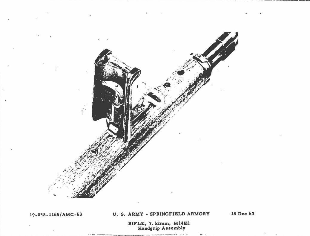
19-0c:iS-1165/ AMC-63
..__.__. .... ------~--------....... -:----ua ...... ......_ ...... ..__ ..,-,.. .... .... ... . ,ftnol!lmn-•--•-ll!-.loll!l.,. •
U. S. ARMY - SPRINGFIELD ARMORY
RIFLE, 7.6Zmm, M14EZ Handgrip A aaembly
I 4 ....... ----· --- · - oo - -- ___ ... -· · - --·---- .
•
18 Dec 63

f. The alias used for the Ml4 (USAIB) vas the atandard Ml~Ml4
llfle alia& and waa too abort to carry the rifle at aling arms. The allaa uaed for the Ml4!2 11 20 inchea longer and baa an extra hook ••
·aeably to peralt the aling to be connected and diaconnected quickly
froa the handgrip an4 bipod (Photographs 1167, 1168).
I• 'l'be butt avivel on the M14 (USAlB) vaa atationary aa on
the Ml and M14 Rifles. the ~~tt avlvel on the M14!2 pivota 90 desreea
to the left aide of the atock to permit ~ide alinalns of the weapon
Photograph 10l6).
c. General Data
1. Tbe Ml4EZ Rifle differa aligbtly from the atandard Ml4 Rifle
and 11 deaigned to deliver accura~e automatic f.ire in the role of the
Infantry Squad automatic Tifle. The atandard Ml4 Rifle 1s used pr~rily
to deliver accurate aemiautomatlc fire by the Infantry Squud.
2. Both aodela are 7 .62aa, magazine-feel, gaa-operated, aboulder
type weapona, and both uae t~e aame sight ayatem.
3. The M14!2 Rifle incorporates a "atratsht Une" atock asse~bly,
euzzle atabilizar, modified M2 bipocl, and a long aling. The barrel and
receiver aroup, and the firin& mechanism are the aame rugged, reliable, . . . M14 Rifle mechaniama and are completely interchangeable between the two
weapons.
D. Phyaical Characteristics of Rifle 7.62~. Ml4E2
Weight of weapon, complete ~tth empty magazine
Weight of weapon, complete with full magazine
Length of weapon, overall
Annunition
Muzzle Velocity
12 lb,l2 oz approx.
13 lb,l2 oz approx.
44.3 in.
7. 6Zt.':ID NATO
2800 1-'PS avg.

I 9-058-11(,7/ AMC-63 U. S. ARMY • SPRINGFIELD ARMORY
RIFLE, 7. 6Zmm, M 14 (USAIB) (Top RIFLE, 7. 6Zmm, M 14E2 (Bottom)
•
18 Dec 63

19-058-1168/ AMC-63 U. s. ARMY - SPRINGFIELD ARMORY
RIFLE, 7. 6Zmm, M 14 (USAIB) ( Top ) RlFJ..E, 7. 6Zmm, M 14EZ ( Bottom )
·-- ·-- - ·-- . -----·
18 Dec 63


II. GENERAL D~SCRIPTIOM
A. Stock Assembly
1. 'lbe atock a11embly of the Ml4E2 Rifle 1a of the "atraight Una"
type with a fixed rear ptstol grip and a folding front handgrip which
liea flat aloag the bottom of the atock when not in use. The locatton·
of the handgrip aaaeably can be adjusted longitudinally for five inchea
im one-inch incrementa to accommo~ate all sunnera. The handgrip ••
a-ably alao haa a altna awivel for use ~en the blpod ia re~ed froa
the weapon• (Photograph ~013).
2. Tbe atock aaaembly also incorporates a rubber recoil pad to
~educe fatigue raaulting f~oe continuous automatic fire. The fol~ing • p •
~boulder reat provide~ vertical control of the butt end of the rifle ..
aad 11 eapeclally uaeful When . ~he weapon ie fired from the prone poet-
tlon.
· 3. The butt awivel pivots 90 degrees to the left aide of the
atock and allowa the weapon to be aide slung for carrying.
1. Muzzle Stabilizer
The muzzla atabllizer elides over the flash suppressor and 11
fastened to the suppressor by a screw and a lock nut. The rifle com•
binatlon tool 1& used to tighten the ecrew and the nut. The stabi-
llzer provrdes muzzle compensation, recoil-braking, and flash aupprea•
alon. It la compensated for right-handed gunners•
C. lipod, M2 (Modified)
Tbe M2 bipod is modified by the addition of a sling swivet and a
longer pivot pin in lieu of the current pivot pin to accocrnodate the
-6-

r: ~·· ~·!!!!!· . -..--!'·::~·-;: ! . ·...__.
I -·
. . • ,.. •• ·,•·.·~ i:" .. I'i~~~~ :: ~· ~; a:·~::,:·.f :· .
__,--- ... -:•· -· ~~~~. ; ·~·:.-,::. -~ ' ' i U'41e'Y·j '~'iP M':r·r •. ., •.. ...______ ;• .. , . . -·"· :..:._. . : .,.: .:. ;~-----· .. ...... ... ..
. . ·.· . I - -·· .. _,_..,.......,........,., ...... ~ • .. . , ....... ,~ ... t-,, ....... ··~
' I I I I I I
I I I I I I t !

1vivel. Tbe 1vivel provides the mounting point for the sling for both
firina and carrying.
D. Sling, Cun
The sling used on the M14E2 ia the long Browning Automatic Rifle
1llna vlth aa extra hook asaembly. Tbe portion of the sling betweea
the baadgrip and the bipod provides additional muzzle control When the
veapoa is fired. When the weapoa is carried, the allng is discoDDected
froa the handgrip aaaembly.
-7-

III. CONVERSION OF Ml4 RIFLE TO }114£2 RlFL!
A. The conversion of the standard Ml4 Rifle to the Ml4E2 configuration
la accomplished in the following =anner:
1. Break the M14 Rifle down into the three main groups, i.e., the
barrel and receiver group, th~ firing mech~nism, and the stock aasembly.
2. Replace the Ml4 Stock Assembly, F7790702, with Ml4!2 Stock
Alaembl7, P7791671 (Photograph 11~9).
3. Reassemble the three =ain groups.
4. Slide the muzzle stabilizer over the flash suppressor, twins
the 7oke over the bayonet lug, and tighten -the screw with th,~ombina~ion
tool. Slide the COIIbination tool over .the heact..of· the screw- and tigbtell·
the nut tacurely.
5. Modif,1 the M2 h:tpod by removing the cotter pill from pivot ptu--tw
the head aatembly. Hold tha jaws in place with f lqer.-, ·and· rem~• pivot
pill, B7791104. Insert pivot pin, B7791669, into awlvel, C7791670, 10
that the loop of the awivel project& forward of the head of the pivot
pin. Insert the pivot pin into the bipod head and through ~he jaws, and
reassemble the cotter pin to the piv.ot pin.
6. A,.emble th:e modified bipod to the rifle g.-a cylinder • arid
tighten with the rifle combination tool.
7. Attach the sling hook assemblies to the bipod swivel and to the
bandgrip pin, pass the trailing end of the sling through the butt swivet
and back through ttie keeper assembly.
·8-

Stock Assembly, F779070Z
M 14EZ, Stock Assembly
/ MZ Bipod (Modified)
--·~·tt!~' . <.~ 1'. ~ .... • .. ----Firing
\...~ Mechanism
19-058-1169/ AMC-63 U. S. ARMY -SPRINGFIELD ARMORY RIFLE, 7 . 6Zmm, Ml4EZ
Conversion of M 14 Rifle to M 14EZ Rifle -·- --·- ·---.. ---··-·------·---- ------- -· ... ... .._ ---- #'..·- . - .. - - - ··- # •• • -
18 Dec 63

1. If the standard M14 Rifle is equipped with a selector lock, in·
stallation of the selector and the selector spring should be accom
plished '' the company arsorer or ordnance P.ersonnel.
-9-

IV. ADJUSlM.ENT OF SLING FOR FIRING
Proper adjuatment of .the portion of the Dliaa between the handgrip
aud the blpod awlvel it necessary to achieve max~ accuracy of auto
matic fire. The allaa ahould be adjusted ao thet the portion between
the handgrip and the bipod ia taut When the handgrip ia pulled rearward
aaainat the atop poaition. Tbia should be accompliahed without undue
&train on the aumier. Tbia adju.tment will maintain proper tension in
~be aUaa aection when the weapon is being fired and will minimize
var~ltion in the alze of the ahot group.
-10·

0
V. DETAlLED DESCRIPTION
A. Stock
1. The stock ia fabricated f~om two separate pieces of walnut wood.
The body of the stock ia made from the standard M14 Rifle stock blank.
The pistol grip ~- fabricated from a separate piece of waln•·t with the
grain perpendicular to the longl~!d!nal axis of the stock. The pistol
grip ia doweled an~ cemented in place.
1.· The croas~sectional area of the forward end of the stock is
greater than that of the Ml4.llfle stock to enable it to withstand th~
stresses applied by the front bandgrlp and the hlgh heat generated by
automatic fire.
B. Pront Handsrip Assembly
1. The bandgrip body is fabricated from aluminum, either a forging
~r a casting, and ia coated with rubber to provide insulation against
beat or colcl. · The handgrip ie attached to a steel mounting block which
ia, in turn, faatl!ned to the stock ··by means of two screws.
2. The handgrip has a spring-loaded latch mechanism which holds
the handgrlp in the closed·position and which acts as a positive stop
in the open position Qgaln~t the pull of the gunner. When the latch
(lo~ated in the back of the handgrlp) is pulled down, tht! stot. pin is
· pulled elear of the block. This operation permits rotation of the
bandgrip to the .~loaed position.
3. The handgrip is moved to the open position when the rearmost
end of the handgrlp b pushed down. The latch will disengage au~o
matically.
·11·

4. The six ~ountlng holes in the bottom of the stock provide five
inches of longitudinal adjustment for the handgrip. The four holes
which are not used are plugged with rubber grommets to prevent foreign
matter from entering the action. The mounting screws are used with two
washers, one is a lock washer and tbe ~ther is a plain washer which
provides a bearing surface between the wood and the lock washer. The
forwardmost hole in the stock is the water drain hole and is not used
for ~djust~ent of the handgrip (Photograph 1170).
c. Shoulder Rest Assembly .
the mounting bracket for the shoulder rest is made of aluminum and
is attached to the stock by two wood screws which are concealed by the
recoil pad. The mounting bracket has a steel pin which engages four
depressions in the shoulder rest-ears. This provides detent action to
hold the should~r rest in the open or closed positions. The ears of the . .
shoulder rest act as a spring and provide constant 'tension against the
ateel pin.
D. Recoil Pad
The recoil pa·, is made of rubber with excellent resistance to oil,
wear, and cold-cracking and is interchangeable fr,om rifle to rifle.
The pad is fastened to the stock by two screws, and the screw holes in
the pad are filled with rubber plugs after assembly to prevent snow
and ice or other foreign ~atter from accumulating in the holes. The
plugs can be removed from the pad by slipping a screw driver blade or
similar flat instrument between the plug and the pad and gently prying
the plug out of the hole (Photograph 1171).
-12-

1. Screw - 7791675 2 . Washer - MS35335-46 3. Burr - 7790474 4. Stock Subassembly - 7791679 5. Grommet .. 11010048 6. Block - 110 10004 7 . Pin - MS51923-252 or
MS39086-202 8 . Swivel - 6008890 9. Pin - MS39086-205 or
MS16562-143 10. Pin - 11010002 11. Pin - MS1656Z-95 or
MS3908-50 12. Spring - 11010003 13. Handgrip- 11010001 14. Pin - MS39086-211 or
MS 16562-14 7 15. Latch Aseemb1y- 11010045
19-058-1170/ AMC-63
·.
lf. S. ARMY -SPRINGFIELD ARMORY
RIFLE, 7. 6Zmm, M 14··EZ Diaa•sembled Handgrip A••emb1y
.. . ... _._ -· ·-- . . - --··-- .. __ ----. .
18 Dee 63

'· ·' "/
19-058-1171/AMC-63
\
1. Stock Suba••embly - 7791679 z. Swivel - 11010046 3. Bushing - 11010047 4. Re•t A••embly - 7791678 s. Screw - 6146873 6. Pad - 7791673 1. Screw - 7791677 a. Plug - 77~ 1674 9. Screw - 7791676
8
U. S. ARMY- SPRINGFIELD ARMORY 18 Dec 63
RIFLE, 7. 6Zmm, M14 EZ Di8aesembled Butt End

E. ·Butt Swivel
The butt swivel fits 'OVer a threaded bushing through wich the lower
recoil pad screw is threaded. The screw draws the bushing agaiost the . . 1tock and provides a bearing surface on which the swivel pivots. The
buthing it prevented from turning when the screw is assembled or dis•
atsembled by pulling down. gently, on the swivel. This action will in-
crease the friction between the bushing and swivel. and the screw will
thread in or out easily.
F. Muzzle Stabilizer
The Duzzle stabilizer is made of steel and fits over the flash sup-
pressor• It is fastened to the bayonet lug of the flash suppressor by
Deana of a tcrew and lock nut. The holes in the stabilizer are unequal
in 1iz~ and in number, and are arranged in such a manner that the es-
caping gases are unequal in volume. This causes a reaction in the
direction opposite the holes. This reaction is designed to compensate
for the forces resulting from recoil and to hold the muzzle relatively
ltable. The rifle is compensated for right-handed gunners (Photograph
1164).
-13-

19-058-1164/ AMC-63 U. S. ARMY -SPRINGFIELD ARMORY
RIFLE, 7.6lmm, M14El Muzzle Stabilizer
Le!t Side View
•
18 Dec 63

Commanding General U.S.A. Veapons Command lock Is.land, Illinois 61202
Commanding General u.s.A. Materiel Command Washington, D.c.
Commanding General
DIStRIBUTIO~
U.S.A. Supply and Maintenance Co~~~~and Washington, D.c.
Commanding General U.S. Continental Ararj Couaand Fort MOnroe, Virginia .
Command General U.S.A. Test and Evaluation Command Aberdeen Proving Ground, Maryland
Commanding Officer llaritan·Araenal AttN: U.S.A. !q~ipment Publications ·Agency Metuchen, New Jersey
Superintendent u.s. Military Academy West Point, New Yo~k
Commandant u.s. l!arine Corps Washington, D.c.
Commandant Marine Corps Equipment Board Quantico, Virginia
President U.S.A. H4intenance Board Fort 1\nox, ICentucky
President U.S.A. Infantry Board Fort Benning, Georgia
Corc:~an~ant U.S.A. Infantry School Fort Benning, Georgia
. ·14-
Copies
4
2
2
2
2
1
2
4
2
4
4

DISTRIBUTION • Continued
Commanding Officer U.S.A. Human Engineering Laboratories Aberdeen Proving Ground, Maryland
Commanding Officer. Aberdeen Proving Ground, Maryland
Commanding Officer Cleveland Procurement District 1367 Baat Sixth Street Cleveland, Ohio
Commanding Officer Boston Procurement District Boston Array Base Boaton, Masa.
Commanding Officar Defense Documentation Center for Scientific and Technical Information Cameron Station Alexandtia, Virginia
Copies
1
2
2
2
1

UNCLASSIFIED
..... ' ......
U NC LASS I lFI JE][)