UNCLASSI FIED AD 4106 197 - Defense Technical … · the models with and without a plate skeg...
96
UNCLASSI FIED AD 4106 197 _ DEFENSE DOCUMENTATION CENTER FOR SCIENTIFIC ANU fECHNICAL INFORMATION CAMERON STATION, ALEXANDRIA. VIRGINIA UNCLASSIFIED
-
Upload
trinhthuan -
Category
Documents
-
view
212 -
download
0
Transcript of UNCLASSI FIED AD 4106 197 - Defense Technical … · the models with and without a plate skeg...

UNCLASSI FIED
AD 4106 197 _
DEFENSE DOCUMENTATION CENTERFOR
SCIENTIFIC ANU fECHNICAL INFORMATION
CAMERON STATION, ALEXANDRIA. VIRGINIA
UNCLASSIFIED

NOTICE: When government or other drawings, speci-fications or other data are used for any purposeother than in connection with a definitely relatedgovernment procurement operation, the U. S.Government thereby incurs no responsibility, nor anyobligation whatsoever; and the fact that the Govern-ment may have formilated, furnished, or in any waysupplied the said drawings, specifications, or otherdata is not to be regarded by implication or other-wise as in any manner licensing the holder or anyother person or corporation, or conveying any rightsor permission to manufacture, use or sell anypatented invention that may in any way be relatedthereto.

R 945
DAVIDSONLABORATORY
Report 945
METHOD OF PREDICTINGCOURSE STABILITY AND
TURNING QUALITIES OF SHIPS
byWinnifred R. Jacobs
U 0 l 0 GMarch 1963

II
DAVIDSON LABORATORY[ REPORT 945
[1 March 1963
METHOD OF PREDICTING COURSE STABILITYAND TURNING QUALITIES OF SHIPS
by
Winnifred R. Jacobs
Prepared under sponsorship ofOffice of Naval Research
Contract Nonr 263(40)Technically administered byDavid Taylor Model Basin
DL Project LZ2388/041
Reproduction in whole or In part is permittedfor any purpose of the United States Government
Approved
S. Tsakonas. HeadFluid DynamicsII,

I
I" ABSTRACT
An analytical method combining simplified potential
flow theory and low aspect-ratio wing theory with empirical
modifications for a real viscous fluid is used to predict the
stability derivatives (first order hydrodynamic force and
moment derivatives) of a family of hulls in order to estimate
the dependence on geometric characteristics of course stability
I and turning or steering qualities. The hulls are Taylor
Standard Series forms with after deadwood removed and have
the same length and prismatic coefficient but varying length-
draft and beam-draft ratios and skeg area. Comparison betweenthe values calculated by this method and those obtained from
experimental measurements shows good agreement. The analytical
method can predict the relative effects of the geometrical
characteristics. Calculated magnitudes are slightly differentfrom the experimental but are on the conservative side. How-
ever, since the hulls tested have the same prismatic, the em-
pirical modification for the rotary moment derivative which is
a function of prismatic coefficient has not been fully tested.
Necessary refinements of the method must wait on analysis of
data on series of forms with different prismatic as well as
Iilength-draft and beam-draft ratios.
R9
L7
SR-94!5

NOMENCLATURE
A profile area of wing or hull, ft 2
AR aspect ratio of wing
B beam, ft
CL dimensionless lift coefficient based onprofile area
Cs two-dimensional lateral added mass coef-ficient (sectional inertia coefficient)
D diameter of turning circle, ftRf + R
D- f r total resistance coefficient of the hull
F force, lb
Ft = Fy measured lateral force coefficient
g acceleration of gravity
H maximum draft, ft
h local draft, ft
hT maximum skeg height, ft
10 moment of inertia of hull, lb-ft-sec2
I added moment of inertia of entrained waterz (see text), lb-ft-sec2
ki
k2 Lamb's coefficients of accession to inertia,longitudinal, lateral and rotational
k 'f
L lift, lb
L' = L dimensionless lift coefficient based onP 2.tH area t.. H
It length, ftA
M = mass of hull, slugs
R-945-iv-

mI 02 hull mass coefficient
mI k km? longitudinal added mass coefficient
2 mI lateral added mass coefficient (see text)
1 m , m + M• longitudinal virtual mass coefficient
!my mt + mL lateral virtual mass coefficient
i ' rotational added mass coefficient (see text)
N yawing moment, lb-ft
SNt N dimensionless yawing moment coefficientI2 t2H
n' 0 z virtual moment of inertia coefficient
iR radius of turning circle, ft
R f frictional resistance, lb
SR rresidual resistance, lb
i r' = dimensionless angular velocity
S Ut dimensionless distance along the path of-7- the center of gravity of the hull
t time, seconds
I U velocity of the center of gravity .of thehull, ft/sec
u x = U Cos x-component of U, ft/sec
Iu Y= -U sin y-component of U, ft/sec
Sx, y, Z coordinate axes fixed in the hull withorigin at the center of gravity
x distance from LCG of center of gravity ofSlateral added mass, ft
Xp distance from LCG of center of pressure ofp lateral force Y, ft
X xT distance from LCG of center of pressure of
tail surface or skeg, ft
R-945I -V-

xs, Xb x-coordinates of stern and bow, respectively
Y lateral hydrodynamic force, lb
Y' = lateral hydrodynamic force coefficient
(3yaw angle or drift angle6 rudder angle
A displacement of hull, lb
p mass density of the fluid, slugs/ft 3
01,2 stability indices
Subscripts (other than those in above definitions)
H refers to bare hull
I refers to ideal fluid
r' refers to derivative with respect to r'
T refers to tail surface or skeg
/3refers to derivative with respect to
R-945-- Vi--

!
TABLE OF CONTENTS
Page
j Abstract iii
Nomenclature iv
Introduction 1
The Analytical Method 3
I Simplified Flow Theory 3
The Assumed Static Force and Moment Ratesfor the Bare Hull 7The Assumed Rotary Force and Moment Ratesfor the Bare Hull 9
3 The Stability Derivatives for Hulls with Skegs 11
The Stability Indices 13
Presentation and Discussion of Results 15
Conclusions and Recommendations 18
1 References 19
I Table I
Figures 1-12
I Appendix - Data Charts
I
I
R-945
i-vii-

INTRODUCTION
The object of the program whose results are re-
ported here was to develop an analytic method for estimating
the course stability and turning or steering qualities of
I" ships. The method, following Martin,' was to be based on a
combination of simplified flow theory and low aspect-ratio
wing theory and was to be assayed by comparison with signifi-
cant empirical results.
Measurements exist of lateral force and moment, on
straight course and in turn (rotating arm tests), on a seriesof eight models (the "840" Series) having the same parent as
I! the Taylor Standard Series without the deadwood (faired-in
skeg) aft (Fig. 1). The models were of the same length and
[ prismatic but with varying beam and/or draft and hence dis-
placement. In addition, there are measurements taken on the
[ models with various flat plate skegs added (Fig. 2), but no
other appendages.
[ Data measured in 1946-47 were reported in refs. 2
and 3 which were concerned primarily with equilibrium turn-[ ing conditions. Measurements were limited in some cases to
a very narrow range of yaw angle around the equilibrium turn-
ing angle for a given diameter of turn. For this reason, the
data on models with skegs reported in ref. 3 are useless forthe purpose of this report. However, unpublished experimental
I data over a wide range of yaw angle at several turning radii,obtained in 1951 at this laboratory, are available for two of
the models with and without a plate skeg extending to the
stern. A third hull was tested here in 1959, without skeg
and with skegs of various sizes, and an analysis of the data
was reported by Tsakonas. 4
I Martin' recently reanalyzed the straight coursedata obtained in 1946-47 on the eight bare hulls along the
R-945
-'-__ _

lines suggested by Thieme,5 Inoue6 and Fedyaevsky and
Sobolev. 7 His method of treating the problem of ship motions
in the horizontal plane is based on a modified low aspect-
ratio wing theory, the Munk ideal moment and cross-flow drag
theory. The last was used in estimating the nonlinear force
and moment range.
The present work considers only stability deriva-
tives of the first order so that the nonlinear variations,
the quadratic and higher terms, may be neglected. Also,
since in the linear range the straight-course data are much
sparser than the rotating-arm data, it was decided to give
more weight to the latter in estimating static stability de-
rivatives. It has been the experience at Davidson Laboratory
that entirely reliable static force and moment rates for
straight-course motion can be obtained from rotating-arm data
at sufficiently large turning radii. This was confirmed in
ref. 4 where rotating-arm results were compared with straight-
course data measured in Tank No. 3 of Davidson Laboratory
using the same towing system and measuring devices as for the
rotating-arm experiments in Tank No. 2. In this way, errors
attributable to inconsistent mechanisms were avoided. The
earlier straight-course data had been measured in Tank No. 1
using different towing and measuring apparatus.
Landweber and Johnson8 have shown that the simpler
methods derived from an alliance of potential flow theory
and low aspect-ratio wing theory can estimate the stability
derivatives as accurately as sophisticated methods based on
more realistic theoretical considerations. The more complex
methods employed in ref. 8 require as many simplifying
assumptions and empirical correction factors if not of the
same kind.
The analytical method adopted here combines the
force and moment approximations which were derived for
R-945
-2--

I
spheroids from potential flow theory by Lambe and for long
I slender bodies with tapered or pointed ends by Breslin' 0
with Albring's" empirical modifications for viscid flow.
[ This approximate method is based on simple concepts, yet
correlation can be considered good between calculated and
Ii experimentally obtained values. Necessary refinements must
wait on the availability of further data on hulls of other
[ prismatic with and without skegs.
This project was sponsored by the Office of Naval
Research under Contract Nonr 263(40) and technically ad-
ministered by David Taylor Model Basin.
I THE ANALYTICAL METHOD
I Simplified Flow Theory
In the potential flow theory the hydrodynamic force
[ and moment rate coefficients, or stability derivatives, of an
elongated body of revolution without appendages are defined
for the linearized region of small angles of attack and large
radii of rotation as:on straight course, r' = t = 0
I H= Y = 0
N' = m' - ml N' (Munk ideal moment)2H i
in turn, around 0 0, (1)
YrA =0
HNr•t=
The notation is that of the Society of Naval Architects and
Marine Engineers (see Nomenclature and Fig. 3). The measured
L lateral force coefficient is defined asF' = Y' - (m' + ml) r'
0y
R-945
-3-

and its derivative with respect to r' as
6F1y Yr (m' + ml) (2)7r- r' ml)
where m' is the mass coefficient of the hull and ml is the0
longitudinal added mass coefficient. Lamb, 9 considering the
added mass term as a hydrodynamic force, defines
Y H m1 k ml where k, is the coefficient of longi-
tudinal accession to inertia. Equations 1 are equivalent to
those derived by Breslin' 0 for a long slender body with
tapered or pointed ends from three-dimensional singularity
distributions.
The first of eqs. 1 is known to be in serious error
in a viscous fluid. To quote Arnstein and Klemperer: "When
an airship is propelled at an angle of attack, lift forces
are created in a similar manner as by the wing of an airplane.
It is true that the airship's shape as a wing is very poor
and its aspect ratio extremely small; but the size of the ex-
posed surface is so great that tremendous aerodynamic force
components at right angles to the flight path can be evoked."', 2
Fedyaevsky and Sobolev 7 have defined the forces and
moments acting on a ship by identifying the body of the ship
with a wing. In this analogy the span of the wing is assumed
to be double the draft of the ship to take into account the
action of the free water surface. Tsakonas 4 shows, by a com-
parison with the wind-tunnel results of Flax and Lawrence,13
that this "solid wall" method of accounting for the free sur-
face effect is correct for moderate speeds when the influence
of wave making may be neglected.
Albring" has derived approximate formulas for the
stability derivatives of a body of revolution with and without
appendages moving in a viscous and eddying fluid. The lift L
on a bare hull is the force developed by the "imagined angle of
R-945
-4-

II
of attack at the stern" of a "correspondingly shaped solid
[ without the effect of curvature." It is a3sumed or taken
from experimental measurements. It acts at a distance xp
[ from the center of gravity and Albring suggests that for most
bodies of revolution Xp = 0 is a good approximation. For a
I bare hull his results are given in ref. 11 as:
on straight course, r' - = 0,
I L' assumed or measured
I Y' = L' + D
% LH (3)
I N' m'- m•l + '•m- ml ft N'i
[ in turn, around • = 0
xY, I -- L' 0o
r H 1H
Albring does not give a formula for N? for the
body without appendages. If one assumes that the center of
pressure does not shift when going from rectilinear to curvi-
linear motion, then
I N = - (J)2 L'•H;t 0 (3a)
I On the other hand, on the basis of Albring's assumption that
the center of pressure is unaltered by the addition of fins
[or skegs, his formula for N1 r' for the body with fins should
hold for the bare hull:
Ix Nr' (X)2Nrl, L - L(3b)
R-945
-5-

x
where 7is implied by Albring to be half the prismatic coef-
ficient of the body. Lh in this case would be the value for
the hull alone, L' since the effects of the appendages arePH'
taken as simply additive.
Equations 3 are derived from simplified flow theory
with the necessary condition that in viscid flow the drag is
not zero, and so at an angle of attack the lift force is not
zero. Under this condition there is an additional moment due
to the action of the lift force at a center of pressure dis-
placed from the CG by x 0 O. In rotation, the angle of attack
at the center of pressure is changed by an amount
tan-1 (- r) _-x-- x -
where
r angular velocity
tr -
U = forward velocity
= length of the hull
R = radius of turn
The additional force coefficient resulting from this change
in angle of attack isx 1
and therefore the rotary force derivative of eq. 1 has an
additional term
_xL
which is equivalent to the negative of the additional static
moment derivative.
R-945
-6-

IIn treating the long body equipped with fins, skegs
[ or control surfaces, simplified theory assumes that there is
no interference between the body and these surfaces so that
[ their separate effects are additive. Tail-surface (skeg)
effects would be derived from the lift on the surface
(obtained either by measurements or by assuming the surface
to be a wing) by following the reasoning of the previous
paragraph. Then
L' assumed or measuredAT
NT T L(T4 _ ( 4 )
Nr,t = - -rT•
N , (7-) L1
i where xT is the algebraic distance between the center of
gravity and the center of pressure on the tail (XT isnegative).I
Equations 3 and 4 are the basis for the calculation
method used in the present report. The assumed lift rates and
the other force and moment rates derived from them will be
discussed in the following sections.
I The Assumed Static Force And Moment
Rates For The Bare Hull
[ The derivative of the lift coefficient with respect
to AL , is assumed as given by Jones' formula for a low
aspect-ratio wing of span equal to twice the ship draft. The
dimensionless lift rate per unit wing area
R-945
ii -7-

6CL = 7 AR
is derived from the consideration of elliptic load distribu-
tions along the chord and the span of a thin foil. Nondimen-
sionalized on the basis of the area H x t, the static ratesof eq. 3 become
7HTH
LI ZrH N r 1(5)y,- + DI
% 0
NI Nhi + -fLý 2~ 1m +PH i H
where DI is the drag coefficient obtained from the TaylorStandard Series curves of resistance 1 4 and xp is taken as thedistance of the center of area of the bare hull profile fromthe center of gravity.
Tsakonas 4 and Martin1 found the Jones formula to be
a good approximation of the static lift rate of the StandardSeries hulls. The fact that the formula does not predict thevalues obtained from measurements on flat plates of the sameprofile does not detract from its usefulness for cambered
wings. Bisplinghoff proves that an elliptically loaded wingmust have an elliptic planform and he points out that it isthe so-called flat-plate chordwise distribution which "compares
very favorably with the measured chordwise distribution ofpressure difference over a slightly inclined, thin, uncambered
airfoil developing the same lift. The only significant dis-crepancies come from within a few per cent chord lengths of
the singularity [at the leading edge]."'" Tsakonas 4 referredto Crabtreelsle work in substantiation of this statement.Crabtree had found that the pressure distribution over a thin
R-945-8-

plate (less than 12% thickness to chord ratio) at various
incidences showed a pronounced suction peak near the leading
edge with a consequent steep adverse pressure gradient and
j laminar boundary layer separation. Since the size and form
of the separation region or "bubble" has a large effect on
the lift, Tsakonas cautioned against use of the experimental
measurements on flat plates to predict forces in the case of
the ship-wing analogy.
The Assumed Rotary Force And MomentIiRates For The Bare Hull
From simplified flow theory the rotary force de-
rivative for a body of revolution without appendages is zero
if the body has fore-and-aft symmetry. For a bare ship hull
without fore-and-aft symmetry, on the other hand, eq. 3 shows
that:
= - H Ni - NIiH hH 'i
[and the measured force derivative with respect to r' (eq. 2):
IF 'H in i'=Y _ (m + m1) - L
where xp is different from zero although small.
From eq. 3a:
=r I LAH A
[which is very small. In addition, as shown by Martin,' there
is a term due to the asymmetry of the rotary added mass of en-trained water, m'. The moment due to this added mass is
Z"-mtr' 5/0 where x is the distance from the center of gravity
of the hull to the CG of the lateral added mass.
R-9 5'U
_ _ _ _ _

Then eq. 3a becomes
Nt mv L(6a)rHz ýH
If eq. 3b is used
N11= -m L? (6b)rHz T r H
where x/I is half the prismatic coefficient. The values ob-tained from eq. 6b have been found to be much closer to ex-
perimental results than those calculated by eq. 6a. The
second term of eq. 6b is approximately 1-1/2 times the first.For this reason, eq. 6b has been taken as the assumed rotarymoment rate. As in ref. 1, m' and 3 have been estimated inzthe following way:
kc' = k k' m2mz7= 2 m! 2 p-
2
xb
m2 = k2 0Cs h 2 dxSs
k2, k' are Lamb's coefficients of accession to inertia,lateral and rotational.
Xs,Xb are the x coordinates of the stern, bow. Jh = local draft
Cs = two-dimensional lateral added mass coefficient.It is determined at each section from the curveson two-dimensional forms of Lewis' sections byProhaska. 17
R-945
-10- I

I
xbx = LCG SX
s
1.The Stability Derivatives
For Hulls With Skegs
[ The force and moment derivatives for the hulls with
skegs are taken as a simple addition of the corresponding
[ forms of eqs. 6 and 4:
L- = L' + L'PH AT
SY= Y' + L'1B H AT
N' = N + (7)A hH -- 4
XT
Nr, -N' L'
I In the present nondimensionalized form of Jones' formula
r L'AT = i (8)
hT = maximum skeg height
The center of pressure of the skeg will be assumed at the
after end of the skeg. Since the length of the skeg is small
in comparison with the length of the hull, any error involved
in this assumption will be small.
IR9I ~R-9k5i
-1i- I

For the case of models with skegs extending to the
stern (Fig. 2), these formulas give essentially the same re-
sults as those obtained by the method suggested by Martin. 1
He included the following terms in his force and moment
equations, respectively, to account for the skeg effect:
- m(xs)ux (k.uy + k'r xs) (from eq. 2 of ref. 1 for Fy)
(9a)and
- xs m(xs)ux (k uy + k'r xs) (from eq. 3 of ref. 1 for N)
(9b)where
m(x s= two-dimensional lateral added mass at the sternper ft
ux = U cos 3 U
uy -U sin 3P -Up
r = angular velocity of the ship.
Yhen the section at the stern is that of a flat plate, ,
m(x )=r-
(see Kuerti, McFadden and Shanks 1 8 ) Iand this term is numerically the same as that given by the
Jones formula for a low aspect-ratio wing of span equal to
twice the ship draft. After nondimensionalizing, since
k2 kI 1, eq. 9a for the added force is approximately
L'(/3 - r' q-~)IAT
and eq. 9b for the added moment is IA T XT)
R-945
-12- 1

where L' is given by eq. 8. Then the force and moment rates
are those given in eq. 4.
j The Stability Indices
The criteria for inherent dynamic stability of a
free body moving on straight course in the horizontal plane
are the damping exponents a. and 02 in the solutionI o.s 025 Oj.s cOaS
1 = le + A2 e , r'= r' e + r' e/3=3e1 2
of the homogeneous linearized equations of motionis
(m' -Y' ) r' - m' As - Y, A =0x r y A (10)
n' r' -N',r - N = 0z r
where Y,, Nb, Y ,.and Nr, are defined in eqs. 6 and 6b for
the bare hull and in eq. 7 for the hull with skegs.
0 10 +
I H
Ian.0 m8
S of (assuming the radius of gyration is equal to ot
I4
xb
Iz =k' C h X~d (ref. 1)
Ii ~and
SPs =_ L •r' Uta s, rs =s- s = -'F
SSolution of the characteristic equation of eq. 10 gives the roots :
R-945
-13-I- n Ifo

-(nztY'-mý')' )±(nz'Yf-m'Nrt,)2+4nztmy [N't, •" x ' °,)N
2n' m 2n'
If al and a2 (or their real parts) are both negative,
the motion is inherently stable in that an initial disturbance
damps out exponentially; the more negative the exponents, the
sooner it damps out and hence the greater the stability. If
a2 is positive, the motion is unstable and the hull cannot
keep to a straight course without application of a corrective
rudder.
The turning characteristics of a hull in turns that
are not too tight (when nonlinearities can be neglected) can
be predicted qualitatively from the al index. A more dynam-
ically stable hull will turn in a larger radius under a given
applied rudder force than will a less stable hull. Conversely,
the more stable hull will require greater rudder force than
the less stable hull to turn in a given radius. On the other
hand, an unstable body may turn in the opposite direction to
that indicated by the applied rudder and will need a com-
paratively large force to bring it around (until it becomes
stable in the turn, but stability in turn is outside the scope
of this report).
R-945-l':- I

I
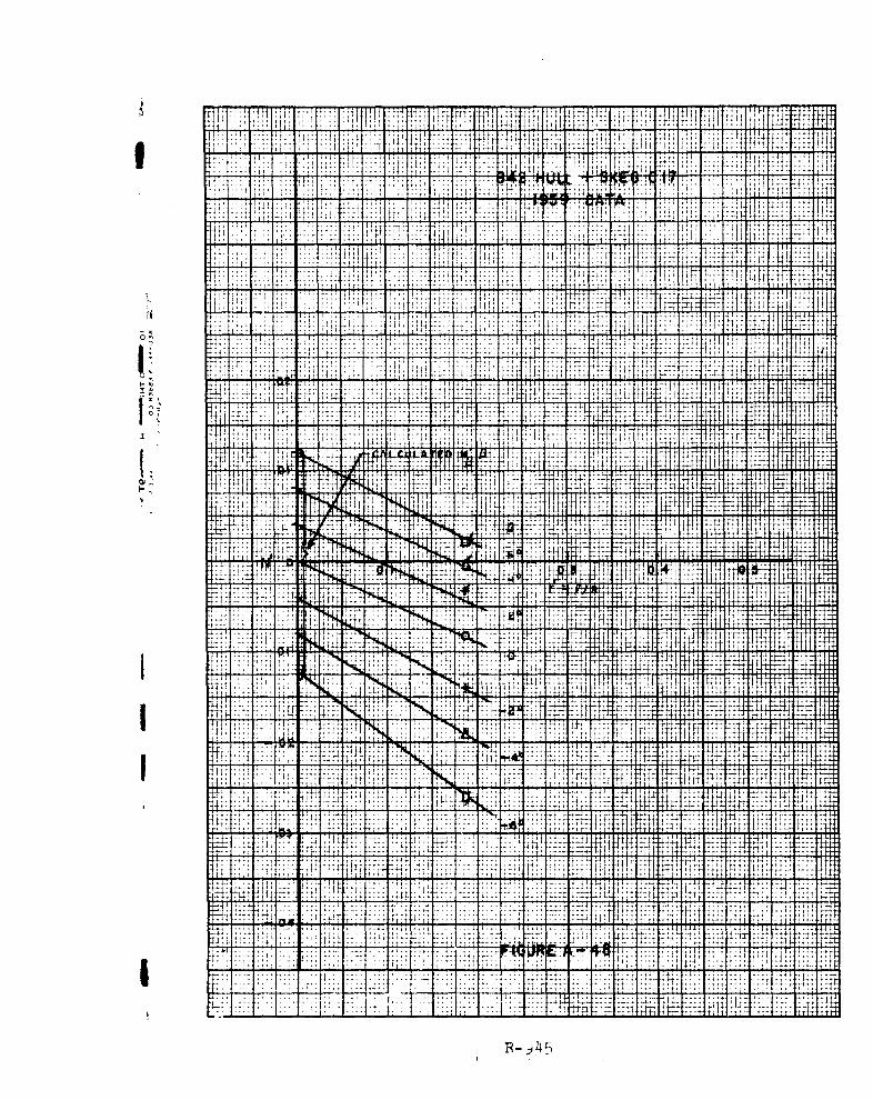
PRESENTATION AND DISCUSSION OF RESULTS
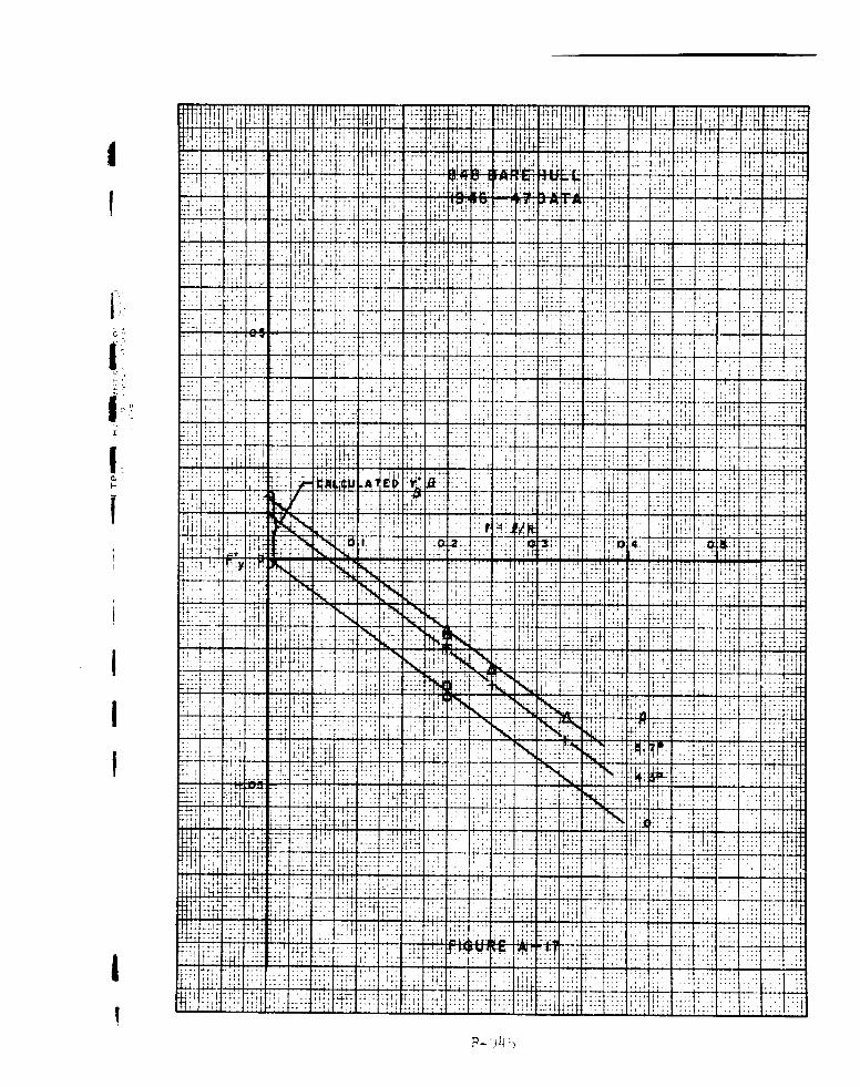
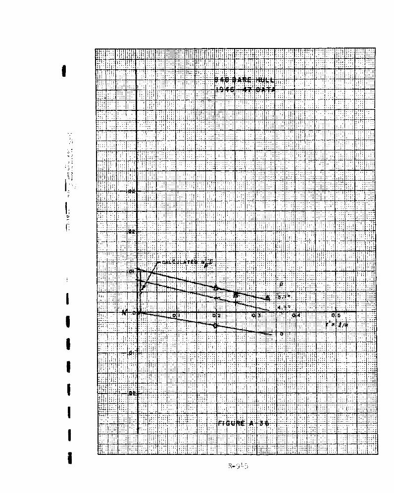
The experimental data measured in 1946-47,2I3 1951
(unpublished), and 1959, are shown in Figs. A-1 to A-48 in
the Appendix, plotted in dimensionless form versus dimension-
loss angular velocity r' = -./R and yaw angle P. Figures
A-1 to A-19 present the measured lateral force coefficientsF' = -(mo + m•) r' + T' and Figs. A-20 to A-38 the measured
y
yawing moment coefficients N' for the bare hulls. Figs. A-39
to A-48 show these quantities for three of the hulls equipped
[ with skegs but no other appendages. Skeg 20 or A is the full
skeg extending to the after perpendicular (Sta. 20), skeg 18
[ or B extends to Sta. 18, 0.1 length from the after perpendi-
cular, and skeg 17 or C to Sta. 17, 0.15 length from the after
[ perpendicular.
The experiments had been conducted at speeds ranging
[ from length-Froude numbers of 0.16 to 0.23, for which range
the implication of the analytical method that wave making may
be neglected is valid. In that speed range the ratio of force
or moment to the square of speed changes only slightly so that
data measured at different speeds within the range can be com-
I pared legitimately.
Table I gives the pertinent characteristics of the
eight hulls and the necessary information for the calculations.
The resistance coefficients Do = 2 (Rf + Rr)/pU2 H were taken
I from the Taylor Standard Series curves 1 4 as the average of the
slightly different values for Froude numbers 0.16 and 0.23.
[ The calculated Y'A and NIP, force and moment coef-
ficients respectively at r' = 0, are also shown on the data
charts in the Appendix. The data plotted at various A versus
r' are faired to the calculated values at r' = 0 with no
[ stretch of the imagination. The static force and moment rate
coefficients are the same whether predicted by the analytical[ method or by rotating-arm data.
R-945
1-15-

Figures 4 through 9 in the text are summary charts
comparing experimentally obtained values for the rotary as
well as static derivatives with those calculated by the
analytical method. These values are shown for varying length-
draft &/H and beam-draft B/H ratios.
The calculated )F'/ r', Nr, and stability indices
a1,2 predict the variations with M/H and B/H correctly but
underestimate the actual magnitudes slightly in the bare-hull
cases, more in the cases of hulls with skegs. The quantita-
tive predictions, however, are on the conservative side.
These comparisons suggest that the simple method adopted here
can be useful for estimating the stability of a given vessel.
The good results Justify use of the ship-wing analogy and the
Jones formula for the lift on the ship as a low aspect-ratio
wing.
The following are specific deductions from the
charts:
1. The static force derivative YV varies inverselywith L/H (or directly with aspect ratio) and directly with
B/H although B/H has very slight effect. Y? is increased by
adding skeg area. An increase in YV is in the direction ofgreater stability.
2. The static moment derivative Nb also varies in-
versely with t/H and directly with B/H. This destablizing
moment rate is reduced mainly by increasing .,/H and by adding
skeg area at the stern.
3. The rotary force derivative 6FI/ r' becomes 3less negative or more positive by increasing t/H, by de-
creasing B/H and by increasing skeg area at the stern. As in
the case of NI, increasing 4,/H or decreasing B/H is in the
direction of greater stability. The variation with B/H arises
from the variation in the longitudinal virtual mass coeffi-
R-945
-16- I

cient. This is the most important effect for the bare hulls,
and is as important as the skeg effect in the case of hull
with full skeg.
14. The rotary moment derivative N', is independ-
ent of B/H. It becomes less negative with increasing t/H
and more negative (towards greater stability) when skeg area
is added at the stern. The variation with tL/H is slight in
1. the case of the bare hulls, more pronounced for the hulls
with skegs.
[5. The stability indices a122 which combine the
effects of static and rotary force and moment rates, show
that stability depends almost entirely on B/H and very little
on t/H in the range tested. Stability increases as B/H de-
creases. On the other hand, an increase in B/H would result
in greater turning ability.
Figure 10 is a summary chart comparing the calcu-
lated Y', N1, Y',, N', and a, with the values from measure-ments obtained by Tsakonas 4 in 1959 on the 842 hull, without
skeg and with three skegs of different sizes. The calculatedstatic derivatives Y' and N' are identical with those obtained
from experimental results. This is also shown in Figs. 4 and7. Figure 10 shows that while the calculated and experimental
j magnitudes of the rotary derivatives and stability index differ
slightly, the stability predictions are conservative estimates.
[ It is also seen that the analytical method can predict the
trend in stability with increase in skeg area. Figures 11 and
12 for the hitherto unpublished 1951 data confirm these con-
clusions.
I
IR-945
LI -17-

CONCLUSIONS AND RECOMMENDATIONS
An analytical method for estimating course stability
and turning qualities of ships has been developed and com-
pared with available experimental data on a series of eight
hulls, the 840 Series, of the same length and prismatic but
varying in draft and/or beam and displacement. The analyti-
cal method combines simplified flow theory with low aspect-
ratio wing theory and makes use of Albring's empirical modi-
fication for the rotary moment derivative.
Encouragingly good correlation is shown between the
calculations by this method and the results based on the ex-
perimental data. However, since the 840 Series is a family
of hulls of the same prismatic, Albring's modification for
the rotary moment rate which is a function of prismatic coef-
ficient has not been fully tested. Necessary refinements of
the method must wait on analysis of data on hulls of other
prismatic, with and without skegs or deadwood aft.
It is recommended therefore that all available data
on hydrodynamic forces and moments, in turn, for other hullforms with different prismatic as well as length-draft andbeam-draft ratios be assembled and analyzed with a view to
checking and refining the method. It would also be advisable
to do further experimentation in still water on families ofhulls such as the Series 60. The latter series has been the
subject of extensive tests to determine resistance, bending Imoments and sea-keeping qualities in waves but the stability
on straight course and behavior in turn have so far been in-
vestiga~ed for only one of the series. 2 0
R-945
-18-

i REFERENCES
1. Martin, M.: "Analysis of Lateral Force and Moment Causedby Yaw During Ship Turning," DL Report 792, March 1961.
2. Sutherland, W. H.: "Progress Report on Related-ModelTests for Turning Studies: Effect of Changes of Beam and
Draft of Bare-Hull Models," ETT Report 338, January 1948.
3. Sutherland, W. H.: "Progress Report on Related-ModelTests for Turning Studies: Effects of Plate Skegs Fittedon Bare-Hull Models," ETT Report 346, April 1948.
4. Tsakonas, S.: "Effect of Appendage and Hull Form on theHydrodynamic Coefficients of Surface Ships," DL Report740, May 1959.
5. Thieme, H.: "On Fluid-Mechanical Principles for theDetermination of Steering Properties," National ResearchCouncil of Canada, Tech. Translation TT-538 (from Schiff
r and Hafen 9:510-518, 1954).
1. 6. Inoue, S.: "On the Turning of Ships," Memoirs of the
Faculty of Engineering, Kyushu University, Vol. 16, No. 2,j Fukuoka, Japan, 1956.
7. Fedyaevsky, K. K. and Sobolev, G. V.: "Application ofthe Results of Low Aspect-Ratio Win§ Theory to theSolution of Some Steering Problems, Proc. NetherlandsShip Model Basin Symp. on the Behavior of Ships in aSeaway, Wageningen, September 1957.
8. Landweber, L. and Johnson, J. L.: "Prediction of DynamicStability Derivatives of an Elongated Body of Revolution,"
I DTMB Report C-359, May 1951.
9. Lamb, H.: Hydrodynamics, Dover Publications, Sixth! Edition, New York, 1945.
10. Breslin, J. P.: "Derivation of Slender-Body Approxima-tions for Force and Moment Derivatives from Three-Dimensional Singularity Distributions" DL TM 134, January1963.
11. Albring, W.: "Summary Report of Experimental andMathematical Methods for the Determination of Coefficientsof Turning of Bodies of Revolution," Conlan 2.[
R-945
-19-

I
12. Arnstein, K. and Klemperer, W.: "Performance of Air-ships," Aerodynamic Theory, Vol. VI, Durand, W. F.,Editor, Julius Springer, 1934.
13. Flax, A. H. and Lawrence, II. R.: "The Aerodynamics ofLow Aspect-Ratio Wings and Wing Body Combinations,"Cornell Aeronautical Laboratory Report 37, 1951.(Published by the Royal Aeronautical Society, ThirdAnglo-American Aeronautical Conference, September 1951)
14. Gertler, M.: "A Reanalysis of the Original Test Datafor the Taylor Standard Series," DTMB Report 806,March 1954.
15. Bisplinghoff, R. L., Ashley, H. and Halfman, R. L.: Aero-elasticity, Addison-Wesley Publishing Co., Inc.,Cambridge, Massachusetts, 1955, Chapter V.
16. Crabtree, L. F.: "The Formation of Regions of SeparatedFlow on Wing Surfaces," Part II, Royal Aircraft Estab-lishment, Report Aero 2578, July 1957.
17. Prohaska, C. W.: "The Vertical Vibration of Ships,"Shipbuilder and Marine Engine-Builder, October- November1947.
18. Kuerti, G., McFadden, J. A. and Shanks, D.: "VirtualMass of Cylinders with Radial Fins and of PolygonalPrisms," NAVORD Report 2295, January 1952.
19. Davidson, K. S. M. and Schiff, L. I.: "Turning andCourse-Keeping Qualities," Transactions of the Societyof Naval Architects and Marine Engineers, 1946.
20. Eda, H. and Crane, C. L., Jr.: "Research on Ship Con-trollability, Part II: Steering Characteristics of theSeries 60 (Cb = 0.60)" DL Report 923, October 1962.
bIII!j
UR-945 U-20-

H ~ 0 H C, UJLCU\ t-r-CU tr\ cu In CUj 0 ctU -4G\ ny tn)U'\W 0ON41 tl- rA 0 '1 0 0
00 \D 0 0 m 0 0~ 0
OHO4H l o LC\0 t-0C\I t- ONCJH 0. a%t- M--tC~~) zd- ) (J~ ~ 0 O~O ~ - L'00 k4 (3 .to 0O~ H O H H 0 0
o 00 O *- . ~ ~ .D -t.8 3 - Z; OO ' Q C U C 'C C!0 H
Ci C;C *000 k* 4 M 1-
4.)C/i 400 H 0 4HrI LONC) 4.n Cp oOOCnA cn (QCO C H 0 U Hm 1WN a\ n tri U 0 O CC) H C: OCUj O' 0 0 0 (m H () . Ln 1f. 0 LCICU t 4 . 0) G\ 00 0 0 HHH'OrI 0 00 -jtO0 * H OH D k~i ( ( 0 0C 0 HC'J 0 Ho
CU
t-C- HOin CU0 t-0 0 CUi w2 ON m~ g in 0 CUj TNEO-- tA oC)~. '(4Y t ZCc ) CU 0 M~ D -t t-
C\A~ 0 -4. CM o H *O-- H\ CU 0 HH 0 0H ;II 0 \ = C\ U; ,0 04
clo4 O C O OCA o- 0A V)O~ U ~ 0C
C1 CU 4 UH -HApt-0 43N -t UC400 C m 0m H ;..........H CU; (o CU..4N.. 01 0W cd Ht OHa H HO H-I f 000r-
0) HE-1 ~ ~ ~ C 000 -- - N (\0 CAU W (\j 00 CU Hd cm r- () t- 0 CU tLn t f C) ON 00 ON 0 m - ri ( ) o 'R 0c t- o tz- Ln H-r,0 4O O H 00 OOHO1 0 0
H0~ 4 ' O C . * 0
0 0,
4C 4 1I K.)o. 0 4.) (1)
d) pq-U) H 4.) 0
a) c.. )H 00 H 0) H - Ho ~ . UN 0 0q q4ý H
C4 Edi 0 to ) P4
4I 0 E32~ - C 4 0 0
02w 4.4'40 .o 0 2 0
H H 0) H 0) cU 4) CUH H-0. CU '04(d r E p. qý4- H- ;-4 ý! 10~ 0 0 :H 3 4ýH ý H CU 4. H CU0 S E4-) 0H ) 40 4 d) '0 C~ CU zt -U) 44 4. r. 7H 0 0 )3 H OH H - t-
0ý 024-) C .) 4) CU H CU d)
Cd 4) 4)4
R-9~45

I IOUII-
w CL
01 .....0
i00
I4
R-4

DEC
II _ _ _ _ _ _ _ _ _ _ _ _ _
rT( , ' 3
SKE
I 'ASm.Il W

+'I'I[
.W/+ r, N X, r
I
. y, Fy
I FIGURE 3. MODEL ORIENTATION IN X-Y PLANE
'R9[IiI
, 9!f

Il CALCULATED (1946-47, 1961)CALCULATED (1959 OATA)
N' I N'j Xp L+
<[- .LCG MOVED .041 AFT (1959)
0.1 2.924.622.92S! 1.65
12 l6 20 24 26 32J/H[ 0.3 _ __--__ _ __ _ _
EXPERIMENTAL,
0 e/H 4.62
2.92 1.1946- 47, 1951
E 2.92 1959
CALCULATED
L' + Do + Do
0.2I
II /IGH
4.622.92I I .65
i 12 16 20 24 28 32
I/H
FIGURE 4. 840 SERIES BARE HULLS DERIVED FROM TAYLOR'SI STANDARD SERIES WITHOUT DEADWOOD AFT
PRISMATIC COEFFICIENT Cp = 0.54
I R-945

I _
CALCULATED (1946-47, 1951)
. CALCULATED (1959 DATA)
S~BH : 4.62 1
0i.
0.1 -
I
12 16 20 24 28 32[ 2/H
EXPERIMENTALo B/H - 4.62+ 2.92 1946-47
[ ~ ~0.1 .}
SYMBOLS WITH FLAGS, 1951
2.92, 1959CALCULATED (1946- 47, 1951)
- - CALCULATED1(1959 DATA)N Nr -MZ.1 - (XO)2 L/
1!•A . 01. fLCG MOVED .04 0 AFT (19E9)
-_ +ALL B/H
0l I I I I12 is 20 24 28 32j 2/H
[FIGURE 5. 840 SERIES BARE HULLS
R- 945

I-
[ + 0 B/H4.62
1.0 -+ 2.92
.CALCULATEDCALCULATED
0 I I I I I
00
12 le 20 24 26 32
SBI/H
-1.0 - EXPERIMENTAL
0 B/H s 4.62"J + 2.92 1946-47
a 1. 651SYMBOLS WITH FLAGS, 1951
-2.0 - 2.92 , 1959
IB/H z 4.62
-3#0 - 0 B/H: 2.92 0
+ B/H, 1.85 + _+ S 2.92
-4.0C MOVED .04 AFT (1959)
FIGURE 6. 840 SERIES BARE HULLS, STABILITY INDICES[

CALCULATED
CALCULATED[ o., N - N'+ +N'Ii0.1 zN +
I 2.92LCG MOVED .04.2 AFT (1959)
4.622.92I .85
0 I I12 6 20 24 28 32[ 2/H
EXPERIMENTAL
[ 0B/H: 4.022.921 1951
[ 0.6 I 2.92, 1959
CALCULATED
Y, Y, +Y'
0.4
y
4.622.92
0.2 1.85
12 16 20 24 28 32
SFIGURE 7 840 SERIES HULLS WITH FULL SKEG (20)
R9

III 0 03
CALCULATEDCALCULATED
I0.2 - )I Y IT
B/H
0. 4.62
24 .92•1.85
[ 012 t6 20 24 28 32P/H
j• EXPERIMENTALd B/H 4.621 1951
[ - 2.921
9 2.92 , 1959
CALCULATEO0.1 CALCULATED
LCG MOVED .041 ALT (8959
[12 1620 24 2e 32
; I FIGURE 8. 840 SERIES HULLS WITH FULL SKEG (20)
R-94J5

iI!
P/14
0 12 16 20 24 26 32
O/H- 4.62
Or
S-1.04CALCULATEDCALCULATED
[-2.0 EXPERIMENTAL
(f1/H s 4.62"-
le 2.9 21 19 51t 2.92, 1959
-3.0[O /H 4.62
[ 8/14 2.92-4.0
9/14: 2.92-
S/H:• 1.65 _
-5.0 LCG MOVE.D .04 AFT (1959)1 °2
I FIGURE 9. 840 SERIES HULLS WITH FULL SKEG (20)
STABILITY INDICES
R9I

EXPTCALCULAT
- -CALCULATEDI'D EXPERIMENTAL AND
- - CALCULATE
al 0.1
N1'r
U 0, - I
0.2 r 0I
IN0. 0
.PROFILE AREA, SQ. FT.
S~FIGURE t0. COMPARISON OF CALCULATED AND EXPERIMENTALj STABILITY DERIVATIVES AND INDICES FOR 842 HULL WITH
15 VARIOUS SKEGS (199 DATA) S R-7 4o )
R-945

[ 1.0-
r 0
1 ~EXPERIMENTAL-- CALCULATED
-i.0 -.- EXPERIMENTAL AND 0.1-IiCALCULATED
0.2
0 0 o
0.1
*_ýN*_
0 +
0.9 1.0 1.1 1.2
II PROFILE AREA. SO. FT.
FIGURE 11. COMPARISON OF CALCULATED AND EXPERIMENTALti STABILITY DERIVATIVES AND INDICES FOR 846 HULL WITH-OUT AND WITH SKEG (1951 DATA)
LI R-945

1.0I.O
0 ______EXPERIMENTAL
_.._ .-- CALCULATED, + 0.|"
--. 0.EXPERIMENTAL AND +
I CALCULATED
I 01 • " " -•'. ---0
I "Fs
-0~
0.2
Y +
I 0
I U-0.1
j0.1 N
*
N0
1.2 PROFILE AREA, SQFT.
FIGRE 2.COMARIONOF CALCULATED AND EXPERIMENTAL
STABILITY DERIVATIVES AND INDICES FOR 848ULWTH
OUT AND WITH SKEG (1951 DATA)
R-945

I ' ISI i
Ii
J DATA CHARTS
[
[ Figures A-i to A-k8
I
I
I,iI

4" P! 4, ' "iI :" :1I
It .I~ .t . i
L
4 41 I 1 4~
171 4 3'
4.;
i -i r Ti~* 4
ý; ithrI4 1d
4 1
11 44 4 ~
pl' 'Ns ~
t it
~~~~~~~~~~~t -- 4 12 41. j : t~ II. il P
~t
4- )

14tI A ttf i 1 44
1 [ V14
4 ý4It
I4 j
It IIi
f
MIY1

tt t4I 4a t 1 rF[ hW q_Hl~ T ft d -1 f~
I-i j JT 4~' ' 1 14
'ji- fT T :44
A~ tf A~ ii 1- :4 II I t'-''I' ' I tF:
f~~ 41 1 t 1
2i' ~ ~ ~ ý I-: fl 44' HJftri4 4 iT '
4p2 1 4i~ T4 IT
4l,1
0 1 r L F
Till] t I 1 .4
i-s t IT ' i t 4 r-44 r
It''
4c t+$-.4I I 14t
It if i-9 T4t5

4I: IT + . K
41,1
t aa T, .1:ý, i t I f-U
1~41
T- t It
[1 4 III
T I -O n~1

44-
~~~~ -It4 7I -, ,$
i1~~~~~~~ lit'- it ,lj~H F'ii~++
I"IT
0,. -+
~~~*77
~~ TI
ý444

1_ý 4
f, ,14i h f!V
It Al t ¼h'V
4414 - I ;.:.;:;Jj 214 T2
I +i i ''f i
'I '14
T. r 4 - -
AII
A ~~ ~ 4 111 ' 4 1 t,~T'' 2
'44'' ''4
-, 5~

U , >~4 ;4 ~ 4 itt, :i i i 1,
T t2
TA
-4 F-
II
It- t, 4" P4 44 7: :H '''
tiI! 17 74' 7 tT
4 4I
~ .44 ~444'2..h -4
44 i -' -ý it' ', !'.B .:T 'JI
R- 9,''' 45

- tý , 4t3V IT iTiLI~T
a, 44
44 rn- ~ p'4 ý IA I *~~ ~ it " Jt tin
-_ I 4 4
* 4--4
IT
IItVj~ -t 4 1 --- bt 44 1 1 4 4
tt -it **4 -1 1~ r :1 it ri; ,
1~~~~~~I TO 1 1 J+4i4444 I . K-4~"~ 4 '~~4 '~
t f, fi4 tfti t ,tT '
I+ I'i+

H_ T 41+i44+
VIM MW m RAM 111M VVI lip, it-, AL41 It "M
J31 W. U RIM H A77
4,1
31'41
41- 1r R T t17t H 11 1 " 11 i I 1 11 7!7ý7 Ij j:_ _1 1 14
r- 'It'll 4ýl; r+441t -fit;ýi' ip ý44t
4-r ;4H,
i-T '4 1, j414 1 jq
I I i'T
it
ý-T4 + -;4T I f .... ....
1, 117 4 t
i- . + 4 T 1ý0'
1.011-4r 14 -f 44
ý44- 4Fýý _ýt 1, ! ' 1411
t t74
14, -f 4' 4 T+I, w -L4 I I
'IT, t -V - it it!-444: til_ý: ý' . ý T . t
4 1 _r
Tt I:- T 4jl jf -I,, 'it idý
114
LLT
4
4,_
it i,#+
Mt 4 1it 4t, f tlil!', ti IT' 1z h- +4,
F 14- A -11i - . i I .- , ,4 f -
4'- t1i r_1 4 j ý ý!-T * ' tT
t+ it t- t.
t1-1 -a AlijN ý4.
41
i i q, d iýiitlf twlml iýý11 1111W il'T*' 4, t
T-1 1 ý447ýi, t 4+ -I- tttt ýft ii 114 1
T iw
T tt.
T:I ýlT + t,T-
t N 4 1
41- T t ±j t44 ;0+4
lit44 t
ARS4
R-)45

, T$meq tmt $
t ý41j 114"Aw"tmwvt'fl ý wc
I 1 4
+
f i t
W 1W It 41 T, 77, tit T it TT
IT
1ý
lit
4 14il f ill,. 114
r i
F tit 4
tit 't 4 i - : T
4't.
'4lit , t
1-t t4 t-t 'fil4J
t I . I I f I
4 4 1
ti
TE 'ji
:f t4l
4
tt
.4 f
4
+
it -i
f;114-
UN iF, 'k F4 f irllý i 4 , ý''T7'+' ; ! r
41 t it -
T
tit
jq tI
it Lft I
T'
fif 4 4,Ir,
-H4
4 4ý'
TT;4 4 11 fit4ý
ol
ITljý
jf f t f.
.66
4 5

........... .......... 444
40-1 It4 iI ý4 _ , 4 1; 1, 4, V R
ILI r, Pit Tf ý' 4, ýA
t ITI
4 It -!I 11-41- 11t4=fý1 Ttý''I., tf +I i- 1ý1 77
ltiý Of I
J" fir IfFI t f ............ if
44;ý jýiý +ýt` 14 0 41 IfH 41, t4 4_4rf f Ff 44 1 f t I tjý
IF, I T-1 ýj 11,t4'
7-F
fI rT IF _tiý
4
f : lit
If
ý7't- I ti 17 t- I , I! if
4 U
44
1 4 f4, f:
ý7 TT
tH 4 ýI4 I, I
'jT1 41 1 441 It
iI IT ý'U td r_;4 i. Jý t
NI t T 1-1 1. ýt
J4 I ýjn
t
4 Iý -T r:L
4 dJ 4 4ý1 ...........;4ýL :1 L I i,
1 t- , 1 Hý tt "t r4 Iý17 T 'I, H H,qt 4 t t "14
4j tT th 4- IP
.41 i4ii_iýt t
tlý fl tttt 1 4. 1
if
r
I+t firt 4. f 41- +
I H i4-
HL U
rb
tq4 -
r 4
44 f t I"
'T
1 fit11 14
'A I it
4p ýHi 4-H t FI'M +
+ 311111ý44;IfH- - 44 141
431 4"t" 1ý1ý a , vi JA rf t. I I, ir itTrIT
Ii" -ýW ' 1 4--4' 411 li-IMai f4 r, I
R-9115

.. ....... ... ......---- ... ..... . ..... .. ..
f
PH
Ili, ý4 -it t t 77 1*1 T tl-r W4 1ý1 IT , tý olýý T;-4
t I I tT r I T
1,, 4 4
4t
ý41 1 4 1-'ý41 i4ft J
:,T
t
liý i It
1.,
T1+ 4
i; +.. 44
t 1 "ýT ýtl 14Hit,
j i ; t ýijijý ýijf t; L"ý,
t 1 14
AT! i
i
i4 H ý,l iiI t
tt i
I ............ -44 1- !1
it14 1ý
t
-4IT! 7 t
!tt
4 , -! r I r rt 4 ii+ 4 4ý
4H r 't I T4 i
4' 1'ý - ----- .1S I f . t 1 it-i- 1'.."
+
4ý ý4ý111 riý - i t, i -H, t -t 11 1 it 4::
N tIP t itrtr - 4, 1 :: +ý41ý, t -t I-H t-- t I I- ýt,
.1 ý!i 4i ',44ý t.;i 41j, 11 1 t" - r
r j: iq I, 14
it 4t
+Tf
if tit
T! 1H,-tý Wim :4 t -1 t-t- t -fi
t 4ýi " +,ý I i ý7 14
1 ,4 1 1t4I
# jj+, .
:f4
41 K4 4-
:+ iTI-H I -! I I ----.4 , tit
+f
i + 114
t TT11 t -4 t-ý ý I . ý; 11 -1
R-945

EpfR H +FR4TEfF
If li,11119 INtHIPM
'b t
m tF v TM
r r! III,
Tit"
I' i
V k, 14 -, qM _1 L411 jNjj 1 7't t +`1 R f R, Offi: if ý,41.4
I I t
1, t r! 4 t, ill i1i
J T
+
ý7 tT 1ý: i: f 4'_Vllý 7 71
i 4 *1 rq L:-
+1 Pý,71' fi,!! i4;;
4-
I t
T +D r7 14
+4-_ý, 1ý " _ýIli ý', , I lt'ý 1ý1:1- 1, tt t - I
I ., - .1jA, wol rjj"jý,;ý ýfj-, I' ýt:ý J T.1 4-it t-t4ý 4 I'Trý,[ F
4 j
HH,
it'. tj 41t H111 I-. 1 - 11"4; 1,7ý: '4
-rq 1 rn"; 1144,1 4ýIT tw - l ý I f 411, liýý IH44 41' '1H ý,i i!ýi
..qj
týj01 t, if I -t1. ITT 1ý: :ýT
7
T:H" E;
J4.
1W-T + 'I t
Hi
ttý4, t; ýfiý ;14
"11, 4 if
'It 41 K -4ý_M T t 141 IT, T +
T iitý44 5t ; t f 4 1',Vi t . i I I I
tit !4 f4
fý,q, 41!ý 4 fI M
14 LL 444 t IT
1:t ±Lt I TI: lý;;J,f -4 ýýr
f ttTV
ý4 jjjtjýt 1, ý-j 1 4- f Ai-_ jjjt 114
I , ý:: " .1ý1 , I t . tJ1 if
U4 ýj I f4it4
OR4 ti A ýIt 711ý "A I f:T1, 1 4 4 1.1 f.,
:4,14 +
4 L,
T 4 IT T I
;T4 :r# q "ll+ iý, 41.
t tj4+i 4
fý ý7i77 41 +Rt, 41ýt L

LH-1+44+ý+4 f
+ 1- 41 j
1141- t 4r4,
j I
161f TM i J14
t P144
-tT 1.ý rr i, T
Iif ',-fr
It - I I t I t -11 'Týl 44 - it
t I4 ii,
t ýTý ý4i ýi t
+
t i fi,+
ti
i tr" I [T,-T t It "I -H'.t
r
if i 'I f
4
ý7 tTif + JiV. . .... T-Y JAJ -f + I'll :4 ýql M IR I T Ll+
Wit Pf+l r 4 -P, iý' Iti
it 4 4 Tt fTi, Ti, I4 f f
14 I-F
J4 1 i, T T' 1 4
!$
7, ;4 + -4
4
--- li VT IT iN li" I t4-
-4;4 4
-!T"44W ; I- N. + T;4
41, 1 .......... J
S41-IF"ll"R T- I X t k -ýr r"T
ý VI +
+ ;I
s t
-441ý
FI-4 it
t
4T 4 1
P -Till mf +
-4-+ 4 t 41 -
il-W, ffNNI+ý + T" H 4-4
1411 77+ tl +
t 14ýf
945

V41M. I rtmil' -XMNI a44
................
14 114
It, Ili I ji
rt IT14- rr; jilii Fij
444 4 t _t
4,;I t
:14
:a;_ IJ 441'J i I 1 4 -11f I MTý t 14 ri , ---tut +LTI+I-t
týl I I i IT 1 ýI 14 j
41- 4 T t
Hj -4q j - IfIT"t!, I I IM:
.n-4
At I! -f- I+ I +t4 4
TT 4,
i 4"IN
ý_F 41 iI, 1 4 t I
J4 41 '1 1 11
-- ---------
+1 41t
!7 , : '7lWIT: 4-71qýii + lit fit
w
IT '4ý
i -I . Iý
4 14T, +
+I ri t+
Iv, t- 4t 147,
T_ýN'4; I I,I P1 ::I Tý'L TqTr,+ i I_ VV Ttll 1 114
ý440 +
4H 44-+ 4 '4
44 4 !1 + I
.4- ItIm M It 4 i+
j-j ý t 1 !;4 f4+44
jj 4+IR4-; f4+
+ 4 T T ltý -I I j"'
_'_4 101 ýP +4.v.
Ail
IT : ItTLI ý ;4 '' ±- . "ý ý - -4
1r,3, 4.1f 14,1 -4 Jý4+
R-9 45

-,7
-.-
U-
14
Li 4I -7
-7-
77- -7--77t-1 7 * , 1 7
-
LAI64
~irk
', -4
la -
T T -7 1 - - -74..
.7 r
-I-.f71
f 4
77 - T r
IT,
44 ,'T t
tF T k it iA I I - - .W. -t-
I4J
NI -a
-14
T- T
I -t 2
41'
Tl, 4j 7 zt ~ -
T II
'2-j ... ...
-ý 7r! t
+4 : f l i Z I- ;4

-i 1'
1-''! 71 *t. ... ... t ..
i -
i iý- ......
0- 4 -
'7F. -7 -ýt L -t- it
IiIA
t 4-4
1, .4 . .t .. -..-
.., . .:i .
.t.
i iF
T t T---- 4 - 4 T7mhW.; - k~ F4Li

Hi 1 1 ~¶T 4TT ! "I rtEtFt t
-T - TT
-£ -r-- -7 : - t'
........... ..... 44 tI; ý
TV T~too
I~~~~7 - 71-,-
I- .,. --
II
5 Tol
IN ..
r ifA~T:if
' ; 17 INI. rI _
7¶7r
R-~ ~

"r 1TTo;,W~~~ 4 T *~~i r~ 1~ :tP J
r T K7 -7_ -~0
~.:7
7'2111*114 ~
-t t
47 oI I ' jIf i
III4IL
i Ii
141
R -9)1

-4
ldi
+j,, f ITM )~
;1 : IIl
t77-
I T t1 4

144 tŽ~ VII " T
f i i f-i I-g4V 7
T f .1 ý; -
F7 T
*SI4
III T

i4 !
F ___,Iý
27ý 4 7 +
Ai.
2777or:I---~14
T~-9~OF

I t tt , -p1t1
-
>4
I -~4-- .
t 4
H -- A 777
L r
7.-~
''%L5*f

ý f I t-
~~~ fl~~~~~4K2pI.;ThI L,
j 2 44 V. ~ ~ .. ~ u ,,
TA 7 -77 7 ,7 ...
- -1
1-4
'4 4
I
411.
ý7- 4_4--44
t: !4,',
1 1 4

rv~r ,
7::: ~ it-"17
- .~J, ',
i-i.1 ,, ,* .
T 7 7
t~,
~
:44
4 4*~ if
4'-. _ _ ___
J. j-4- -- a
TKLi
4 44
-77 -r-

fill
II A'.-
-Tr
I T,
T , it 17
A---
I t17
7,, 14 "
1-14 ' f "
-7I44~~~i
iI 4~
11 , '

ýiL ! Thil i -
I2 T
1 41
77 -- ýT
4 11
I)~I;. IT..K-I
4, ,. I
V tj
~ 2K 7
7I ' 4ý
T -
'I 4-'IT
R.9

F!4
I 4 7- t-
p it f!1
i:-i7 777 1 12 ý- ýi +I- T-, 1 6 I
~rn r:7T7
F11
.; H + H -FI. It--~~7T
tt 1 -
t;;
:+1.
-1 -, 77-;
rt 'I
it~ 111
tit
4-11
R- 945

f , I ,7-,I q .
.'. ,IV
-T 1 i ~A' -. i !
it -, -A,
T P,. ,
I.
77,
r~ it
j4't
ILL , I'I'
41 ]4 4tt''
7.1
1- tBI

T FTT'FlIr lit111 tllt9 15
'i 6i 4 1
___j ;ýtýii J
I r
t .4
t~ f
~~~ T ' I 2
4-- 4;.
R- c)- 5 4 1 WH

.~-: --HT j
t t I,
4- 4-4.X.2!f It. f le!.4,
II, -,I TT -7
44
.4 1 . .- . .- . . ...
14
fti I'' r ' J-
I ~ 4*
-V - '42.4,
+ 74 '4~ ''4-4 4 ,.
II
I LI
74''': 4 4'
"14
4--
1 -7 17 -I rF;~
Ii'- )'45

I t-~ ~ ~ : 4 -1 ''- - --- - --
TI I II
I _ 17-
1~ -777~
h +4 1
L tit T~

,.4rhij 1 TJT jTv fhT 7 ~t H I I r
,:.ý
itdia
7 .... ...,
0 --
'Nil
-t j t '
.r ~ ~ ~ -l -t:i
4!- - T
-17-
1* 1 1 TL..~.. ... ... J j~1
71 L 1 1'
4i
I-I-
411
T7 --I-- t
-k 7:4t+ !W ', 7
.. 1; I-I 1 .1

.ii
l', 4. i
II
.-,
4,-
: -I '
tt .i,'
I ft
- - -
-~
41
It
1
IIo
T I
I .- -I
:
t T I-~4-- -7
- 4-
~~,:L;~i I 4ýVf,
- -~- -- '- R-945-
~ý7 !
;fr j'!- - - -
-t i
4~i 71 - - -
7-77 'i I
I 1
44i -'q ': 7,7.
_~~ ~ 7--77- - -
144
7E
-- -* - -q
T. I
7- 7, V- - :77
l-I7
- ~ ~ ~ ~ T - -7 -- ---4
L 4
4t 1-- -4 -
I 14 . 1. - -:
IT ' T
-~~~ 77,- -. - I ~ 7 .2- -- ~--
1 i q .. .. "7 -- 4 .4.
4J -I 0
I 7 -,
L I- +i4
7± 7 -7 77 + ,L iL
'V .-,--I - - - - R-9 45 -- ~

;;4 ýhIt ~totf 2 if7'ThT~~+i~ 1414
I t
!4 j4 rt.t'~ '*
I-71
14jt4-
+ +
I~i.2k.TfT~..---~ ~7
;ýja i.Ij
L4

IIT
I dt
t IL I
7-' tT. U
t-I2 . 1
t' V I
T~~ ~i
IitT 7__
I-tT' !t1

Ip "I T i' L r ~ hT I 1ft1 i' r'T ' I V
1`07 I;4 w t i I i7
-- t1r- ~ ~
.~~ T
P431 _:
t44 .41ft: t
II- -77 -T-l-,' r -
-r 77 1 -7
II'I I- .1
4-1-
-7 1. , , :
*~~J To>- I~--~

I T 11
-- "-,-i -1 -7 q
,V-7777 _77
4. 1I
I;"4,f. 4,KI7
IT~ ~ ~ j9 7-

1T1
444.
I T
j~~.i~ 7.,-'-
TIF
77- -T--- rr- :4 -
T,--!t ,, I . 1 41
.~ .~ .1 TI
4-! -I - -
I,
- ~R- 'Pt 5

I,~ if t 1 1i
.... .. .1 4
Ih I T2* ' I t
-1TFT 7 -- 7 -
4' t , 4' i
4 11
wIiT 4. ii -F -- '
4 ff
CIOrýT4 177
51
1 44
4. 4:;. 7 1 4 ¼T T'4:rP.;;f4
tI ~

i I 4
4 ~~' '
w od-~f T.-.7'
I-I .
.2 ti :. j:'I 1 ' 1 - ,.- - -
7.77 TT' tT2
4'' H~ --
7. 7 4
II;fNý
11
_41

~~4 1rr N!r
.1:4 ,f -W 4i:1: ifT 4;14 'T tTL'
j~ -t
Tll
T~t_17 -- T7 j,:
I:J.,
46;
71t 77 4_~7 KTit" 11t
71;, .- N -
i- - N 1. T4--t1
t *1~' 1+
i t 'P l . . ~ 2';
'iit
77.~~~! g1 ,:-
- iFm %.iý. 4.1 .j' ", - 1 +IL4

IT~rj -,t 2 j-;
t44 IT ; 1' 4
~~j~ 1 *~i >
t, t t j i
I -
44,-- 1 4 1 T r~
I '4
.7r ... V
t t'Ir r
11, ~ ~ ý * V 1
- T
: n i 4Ij 44 .
i'~ V L~ A II
V. R4i--r~2
4 I.,
F':7T~ .1~. ;
_A t T. It~
4 "I

C1 1,1 *A-1..1F1
't i, -4 iq T 941. .44413MM;q
Fi I T41> j . . T
1--~4 4 4 i
414 1r.Th4 1 4;.4.. F F,'' '''' ' IF4, F~4:4::ji44 4
,,,..,,~ ~ ~ ;,4If4f ;4
"4 4
f 4u
inb 44. 4 4 r4
4-1 .. 4,~ K1 1- ;..1~ t.,
-1 ý14 it 1
~~K TF~~~T~~ t7t~ FV2Wid
'14
it ii.
"I I 4 4 i- -
1J, 14 1 jj
I +, T,
t42
114 1 1i. 1
Tt1 J:I. 1.ý4
Jt:. 41 £ t; 4 1 Y
4- v4-t-7 r+¶2

DISTRIBUTION LISTCopies Copies
6 Naval Research Laboratory Pennsylvania State University 1[Washington 25, D. C. University Park, PennsylvaniaDirector Attn: Ordnance Research Lab.Attn, Code 2021 (Library) Director
1 New York Naval Shipyard Philadelphia Naval Shipyard 1Brooklyn, New York Philadelphia, PennsylvaniaAttn, Commander Attn: Director
1 New York University Portsmouth Naval Shipyard 1University Heights Portsmouth, New HampshireNew York 53, New York Attn: CommanderAttn: Dept. of Oceanography
Prof. W. J. Pierson, Jr. Puget Sound Naval Shipyard 1Bremerton, Washington
1 Norfolk Naval Shipyard Attn: CommanderPortsmouth, Virgini aAttnt Commander San Francisco Naval Shipyard 1
San Francisco, CaliforniaOffice of Naval Research Attn: Commander1000 Geary StreetSan Francisco 9, California Society of Naval ArchitectsAttn% Commanding Officer and Marine Engineers
74 Trinity Place1 Office of Naval Research New York 6, New York
1030 East Green StreetPasadena 1, California St. Anthony Falls Hydraulic Lab. 1Attn, Commanding Officer University of MinnesotaI Minneapolis 14, Minnesota
1 Office of Naval Research Attn: Prof. L. G. Straut346 BroadwayNew York 13, New York University of CaliforniaAttn: Commanding Officer Berkeley 5, California
Attnt Dept. of Engineering1 Office of Naval Research Prof. H. A. Schade 1
John Crerar Library Building Prof. J. Johnson 186 East Randolph Street Prof. J. V. Wehausen 1Chicago 1, IllinoisAttn: Commanding Officer University of Maryland 1
College Park, MarylandI Office of Technical Services Attn: Institute for Fluid Dynamics
* Department of Commerce and Applied MathematicsWashington 25, D. C.Attn: Technical Reports Sec. University of Michigan 1
Ann Arbor, Michigan1 Pearl Harbor Naval Shipyard Attn: Dept. of Naval Architecture
Navy#128, Fleet Post Office Prof. R. B. Couch, HeadSan Francisco, CaliforniaAttn, Commander
AI.'
II I,- - - - .. - - -
DISTRIBUTION LIST
Copies Copies
1 Department of the Navy Military Sea TransportationWashington 25, D. C. Department of the NavyChief, Bureau of Yards and Docks Washington 25, D. C.Attn, Code D-400 Attn, Commander
Research DivisionNatil Aeronautics and Space Adm.
2 Iowa Inst. of Hydraulic Research 1512 H Street, N.W.State University of Iowa Washington 25, D. C.Iowa City, Iowa Attnt DirectorAttnt Prof. H. Rouse, Director
Prof. L. Landweber National Bureau of StandardsWashington 25, D. C.
2 Inst. of Mathematical Sciences DirectorNew York University Attn: Fluid Mechanics25 Waverly Place Dr. G. B. SchubauerNew York 3, N.Y.Attn: Prof. J. Stoker National Science Foundation
Prof. A. Peters 1420 H Street, N.W.Washington, D. C.
1 Long Beach Naval Shipyard Attnt DirectorLong Beach, CaliforniaAttnt Commander Aeronautical Research Associates 1
of Princeton, Incorporated1 Mare Island Naval Shipyard 50 Washington Road
Vellejo, California Princeton, New JerseyAttnt Commander Attn: Dr. Bernard Paiewonsky
1 Maritime Administration University of California 2Department of Commerce College of EngineeringWashington 25, D. C. Dept. of Naval ArchitectureAdministrator Berkeley 4, CaliforniaAttn: Office of Ship Construction Attn: Dr. H. A. Schade
Mr. Vito L. Russo Prof. J. V. Wehausen
1 Maritime College Colorado State University 2State University of New York Dept. of Civil EngineeringFort Schulyer Fort Collins, ColoradoNew York 65, N. Y. Attn: Prof. J. CermakAttn2 Engineering Department Prof. L. V. Baldwin
Prof. J. J. FoodyCornell Aeronautical Lab., Inc.
Mass, Inst. of Technology Applied Mechanics DepartmerltCambridge 39, Massachusetts P. 0. Box 235Attnt Dept. of Naval Architecture Buffalo 21, N.Y.
and Marine Engineering Attne Dr. Irving C. StatlerProf. L. Troost, Head
A

I,!g
DISTRIBUTION LIST
[Copies Copies
1 U.S. Army Trans. Research Armed Services Technical 10
and Engineering Command Information AgencyFort Eustis, Virginia Arlington Hall StationAttnt Marine Transport Div. Arlington 12, Virginia
Commander2 U.S. Coast Guard Attn: TIPDR
1300 E. Street, N.W.Washington 25, D. C. California Inst. of Technology 1Attnt Sec., Ship Structure Pasadena 4, California
Commandant Attn: Prof. T. Y. Wu
1 U.S. Merchant Marine Academy Charleston Naval Shipyard 1Kings Point, L.I., N.Y. Charleston, South CarolinaSuperintendent Attnt CommanderAttn: Capt. L. McCready, Head
Dept. of Engineering Colorado State University 1Dept. of Civil Engineering
1 U.S. Naval Academy Fort Collins, ColoradoAnnapolis, Maryland Attn, Fluid Mechanics BranchSuperintendent Prof. M. Albertson, HeadAttnt Library
David Taylor Model Basin 75S1 U.S. Naval Post Graduate School Washington 7, D. C.Monterey, Calif6rnia Commanding Officer and Director
Attn: Superintendent Attn: Code 513
1 U.S. Naval Proving Ground Chief of Naval Research 1Dahlgren, Virginia Department of the NavyAttn, Commander Washington 25, D. C.
Attn: Code 4381 U.S. Naval Ship Repair Facility
San Diego, California Department of the Navy 2Attn, Commander Washington 25, D. C.
Attn. Chief, Bureau of Weapons1 Webb Inst. of Naval Architecture
Crescent Beach Road Department of the Navy 10Glen Cove, L.I., N.Y. Washington 25, D. C.Administrator Chief, Bureau of ShipsAttn, Technical Library Attn, Code 335 (Tech. Info. Br) 3
310 (Res. and Devl. 11 Woods Hole Oceanographic Inst. 420 (Prelim. Design) 1
Woods Hole, Massachusetts 421 jPrelim. Design) 1Attno Dr. C. Iselin 440 Hull Design gr) 1
442 Scientific and 11 Boston Naval Shipyard Research)
Boston, Massachusetts 341B IAttn: Commander 345 1

DISTRIBUTION LIST
Copies Copies
Dartmouth College University of Minnesota IThayer School of Engineering St. Anthony Falls Hydraulic Lab.Hanover, New Hampshire Minneapolis 14, MinnesotaAttn: Prof. Sidney Lees
New York University 12 Douglas Aircraft Company, Inc. College of Engineering
Aircraft Division Dept. of Meteorology and OceanographyLong Beach, California University HeightsAttn: Mr. John Hess New York 53, N.Y.
Mr. A. M. 0. SmithOrdnance Research Laboratory 1
2 Electric Boat Division Pennsylvania State UniversityGeneral Dynamics Corporation P. 0. Box 30Groton, Connecticut University Park, Penna.Attn: Mr. H. E. Sheets Attn: Dr. George F. Wislicenus
Mr. R. J. McGrattan
Southwest Research Institute 1Hydronautics, Incorporated Dept. of Mechanical SciencesPindell School Road 8500 Culebra RoadHoward County, Laurel, Md. San Antonio 6, TexasAttn: Mr. Phillip Eisenberg Attnt Dr. H. Normal Abramson
Hydro Space Associates Robert Taggart, Inc.3775 Sheridge Drive 400 Arlington Blvd.Sherman Oaks, California Falls Church, VirginiaAttn, Dr. Leonard Pode Attn: Mr. Robert Taggart
University of Illinois Technical Research Group, Inc. 1College of Engineering 2 Aerial WayDept. of Theoretical and Syosset, New York
Applied Mechanics Attn: Dr. Jack KotikUrbana, IllinoisAttn: Prof. J. M. Robertson Vidya
1450 Page Mill RoadIowa Inst. of Hydraulic Research Palo Alto, CaliforniaUniversity of Iowa Attn: Dr. A. H. SacksIowa City, IowaAttn: Prof. L. Landweber University of Michigan 1
Dept. of Naval Architecture and3 Mass. Inst. of Technology Marine Engineering
Cambridge 39, Massachusetts Ann Arbor, MichiganAttn, Prof. Kerwin Attn: Dr. Finn C. Michelsen
Dr. E. CovertMr. H. Moses

7- - - - -- - --- --- - - - - --
A0 U.4 NO *.
g4. 4 0 N0.-.IWO
o HU1,14.. 0. .,.'a 0 4 6 . .a0. Q .4.0
S0.0
4 0I US I 4j. 0j .-4 1.01 410,
hoc 45UItCa4.. ~ 0 05. 0 *.iis
a-le I A 54O3I-i.-I
' 9.0t fi Vv" IV4 0 ~mill 0 0.4..4 it 0 05a1I MA vi
0 11 In04
I * N 045,
00:1 .4 4.41 r.0
U~~o~ ~o ~ i 4 Aji
0 a lo jI40 0is , 3 0 a1, of
L~. -. - -~ -. -, -,.U~ - --------