UML - Searchstaff.um.edu.mt/ecac1/files/csa2130_UML.pdf · design effort. • Unified because it...
195
UML FUNDAMENTALS © 2001-2004 - Dr. Ernest Cachia
-
Upload
hoangkhanh -
Category
Documents
-
view
229 -
download
2
Transcript of UML - Searchstaff.um.edu.mt/ecac1/files/csa2130_UML.pdf · design effort. • Unified because it...

UML FUNDAMENTALS
© 2001-2004 - Dr. Ernest Cachia

UML
Unified Modelling Language
Visualising and documenting analysis and design effort.
• Unified because it …– Combines main preceding OO methods (Booch by Grady
Booch, OMT by Jim Rumbaugh and OOSE by Ivar Jacobson)
• Modelling because it is …– Primarily used for visually modelling systems. Many system
views are supported by appropriate models
• Language because …– It offers a syntax through which to express modelled knowledge

UML Ancestry (visual)
Booch '91 OMT-1 OOSEOther
Booch '93 OMT-2
UM 0.8
UML 0.9/0.91
UML 1.0
UML 1.1Industrialisation
Sta
nd
ard
isatio
nU
nific
atio
n
Partner'sexpertise
Publicfeedback
Jun-Oct'96
Sep1997
Jan 1997
June to Oct 1996
1995
Fra
gm
enta
ry

Further (latest) UML Evolution
1 9 9 7( a d o p t e d b y O M G )
1 9 9 8
1 9 9 9
Q 1 2 0 0 1
Q 4 2 0 0 1
E d i t o r i a l r e v i s io nw i t h o u t s ig n i f i c a n t
t e c h n ic a l c h a n g e s .
2 0 0 2
U M L 1 .1
U M L 1 .2
U M L 1 .3
U M L 1 .4
U M L 2 . 0I n f r a s t r u c t u r e
U M L 2 .0
U M L 2 .0S u p e r s t r u c t u r e
U M L 2 .0O C L
c o m p o s i t i o n( w h o l e - p a r t )
r e l a t i o n s h ip
d e p e n d e n c yr e la t i o n s h i p
( L o o s e l y a d a p t e d f r o m K o b r y n , 2 0 0 1 )

UML Partners
The list is quite an impressive one:
● Hewlett-Packard
● IBM
● Microsoft
● Oracle
● i-Logix
● Intelli Corp.
● MCI Systemhouse
● ObjectTime
● Unisys
● Sterling Software
● Rational Software
● ICON computing
● Platinum Technology
● and others…

and so…What is UML?
Based on the previous three slides…
• A language for capturing and expressing knowledge
• A tool for system discovery and development
• A tool for visual development modelling
• A set of well-founded guidelines
• A milestone generator
• A popular (therefore supported) tool

and…What UML is not!
• A visual programming language or environment
• A database specification tool
• A development process (i.e. an SDLC)
• A panacea
• A quality guarantee

What UML can do for youHelp you to:– Better think out and document your system before
implementing it– “forecast” your system– Determine islands of reusability– Lower development costs– Plan and analyse your logic (system behaviour)– Make the right decisions at an early stage (before
committed to code)– Better deploy the system for efficient memory and
processor usage– Easier maintenance/modification on well documented
systems– Lower maintenance costs– Establish a communication standard– Minimise “lead-in” costs
UML componentsUML
Views
Diagrams
Model Elements
General Mechanisms
Functional Non-functional Organisational
9 diagrams(see further on)
Symbology / notation
Adornments Notes Specifications

The Case “for” Diagrams
• Aesthetic
• Descriptive
• Compressive
• Simple
• Understandable
• Universal
• Formalise-able / Standardise-able

The Case “against” Diagrams
• Not inherent knowledge
• Easily cluttered
• Require some training
• Not necessarily revealing
• Must be liked to be accepted and used
• Effort to draw

UML diagramsUML diagrams
Use-Case
Static Structure
State
Activity
Interaction
Implementation
Object Class
Sequence Collaboration
Component Deployment

UML Diagrams (comparative slide)
� Use-Case (relation of actors to system functions)
� Class (static class structure)
� Object (same as class - only using class instances – i.e. objects)
� State (states of objects in a particular class)
� Sequence (Object message passing structure)
� Collaboration (same as sequence but also shows context - i.e. objects and their relationships)
� Activity (sequential flow of activities i.e. action states)
� Component (code structure)
� Deployment (mapping of software to hardware)

UML Diagram Philosophy
Any UML diagram:
• Depicts concepts
– as symbols
• Depicts relationships between concepts
– as directed or undirected arcs (lines)
• Depicts names
– as labels within or next to symbols and lines

The Main 4 UML Diagrams
• Use-Case
• Class
• Sequence
• State
Examples are depicted on the following
slides.

The Use-Case Diagram

The Class Diagram

The Sequence Diagram

The State Diagram

The Other 5 UML Diagrams
• Object
• Collaboration
• Activity
• Component
• Deployment
Examples are depicted on the following slides.

The Object Diagram

The Collaboration Diagram

The Activity Diagram

The Component Diagram
The Deployment Diagram
UML Relationships

Some Points to Ponder
1. How would you justify the use of UML in any IS project to programming personnel?
2. What is the difference between static and dynamic UML diagrams?
3. Why does UML attempt to model systems with a heavy emphasis on graphic notation?
4. Why does UML not restrict itself to one type of diagram?
5. Is UML restrictive to system development? Justify your reply.
6. A common misconception is that systems built using UML are quality guaranteed. Discuss this issue and present (write down) your reasoning.

Workshop Activity -7-
Try textually describing the software controlling production of a large-scale pre-packed food company (weather/calendar/market controlled).
Once done, try describing the exact same system diagrammatically.
Draw some conclusions from your work.

UML Development Model
UML DM
Requirements Gathering
Analysis
Design
Development
Deployment
The next slides will outline the above phases

Requirements Gathering (1/2)
Determine what the client wants
• Business process elicitation– Tool: Interview; Questionnaire; Observation;
Experience
– Product: UML Activity diagram
• Domain analysis– Tool: Interview; Noun-Verb extraction; Observation
– Product: UML HL Class diagram; textual supporting data

Requirements Gathering (2/2)
• System context determination– Tool: Observation; Process walk-through
– Product: UML Deployment diagram
• System requirements elicitation– Tool: JAD moderated session
– Product: Refined HL Class Diagram; UML Package diagram
• Phase outcome presentation– Tool: n/a
– Product: n/a

Analysis (1/2)
Unfold a detailed understanding of the problem
• Determine system usage (Actor determination)– Tool: JAD session; User interrogation
– Product: Use-Case diagram/s
• Expand Use-Cases (Fleshing-out)– Tool: Further user interrogation
– Product: Textual supplement to Use-Case diagrams
• Refine Class diagram– Tool: JAD session; Observation (of JAD)
– Product: Refined Class diagram (inc. associations, cardinalities/modalities, generalisations, etc.)

Analysis (2/2)
• State analysis– Tool: Thought
– Product: State diagram
• Interaction analysis– Tool: Internal experience (Use-Case + refined Class + State)
– Product: Sequence and Collaboration diagrams
• System integration analysis– Tool: Observation; walk-through, interrogation
– Product: Detailed deployment diagram

Design (1/2)
Analysis ↔ Design (until design is completed)
• Develop and refine object diagrams– Tool: Operation analysis
– Product: Activity diagrams
• Develop component diagrams– Tool: Programmers; system component (and interaction)
visualisation
– Product: Component diagrams
• Start thinking about deployment– Tool: Analysis of component structure and their
integration (from previous); external system co-operation
– Product: Part of deployment diagram from analysis

Design (2/2)
• Prototype development (GUI)– Tool: JAD session previous and new; previous use-case
diagrams
– Product: Screen prototypes and shots
• Testing of design– Peer-developed test cases based on existing use-case diagrams
– Product: Test cases (scripts)
• Design documentation structure– Tool: Designer input and document configuration tools
– Product: Document structure

Development (1/2)
Programmers’ realm – should proceed swiftly if right effort was initially invested
• Coding– Tool: Programmers using class, object, activity and component
diagrams
– Product: Code
• Testing– Tool: Back-and-forth from the coding activity using the test cases
designed in the design phase
– Product: Test results

Development (2/2)
• Implement, connect and test UIs– Tool: UI development environment; programmer interaction
– Product: Full working system
• Finalise documentation– Tool: programmer input; inspection
– Product: Full system documentation

Deployment
Software to hardware mapping and consideration of interacting systems
• Backup and recovery strategy– Tool: Initial requirements; system nature considerations
– Product: Crash recovery plan
• Installation– Tool: n/a
– Product: Deployed system
• Installation testing– Tool: Implementation of test sequences including backup and
recovery
– Product: Final (actual) test results

Workshop Activity -8-
Internally within each team, divide up into “client/analyst”, “object engineer”, and “programmer/documentation specialist” and try developing a basic DVD rental control software system using basic UML notation so far covered and according to UML DM. Request trainer inspection after every phase. Coding need only be carried out at a highly abstract structured text or pseudo-code level.

Use-Case Diagrams (UCDs) (1/2)
• A use-case is…– a simplification of (a part of) a business process model
– a set of activities within a system
– presented from the point of view of the associated actors(i.e. those actors interacting with the system)
– leading to an externally visible result
• What is the model supposed to do?– offer a simplified and limited notation
– allow other diagrams used to support (realise) it
– combinatorial with prototypes as complementary information
– not intended to model functional decomposition

Use-Case Diagrams (UCDs) (2/2)
Components: use-cases and actors
– a use-case must always deliver a value to an actor
– the aggregate of all use-cases is the system's complete functionality
Goals:
– consolidate system functional requirements
– provide a development synchronisation point
– provide a basis for system testing
– provide a basic function-class/operation map

UCD Components
• The use case itself is drawn as an oval.
• The actors are drawn as little stick figures.
• The actors are connected to the use case with lines.
Actor symbolUseCase1
Use-case symbol
Relationships and connectors
System boundary
System
Actor1
«extend» «include»

UML Actors
• An actor– Is a class that forms a system boundary
– participates in a use-case
– is not within our responsibility as systems analyst/s and/or designer/s
• Examples are– end-users (roles)
– external systems (co-operations)
– time related events (events)
– external, passive objects (entities)

UML Actor Classification
�A primary actor uses the system's primary functions (e.g. a bank cashier);
�A secondary actor uses the system's secondary functions (e.g. a bank manager, system administrator);
�An active actor initiates a use-case;
�A passive actor only participates in one or more use-cases.

Identifying UML Actors
Ask yourself the following questions:
� Who are the system’s primary users?
� Who requires system support for daily tasks?
� Who are the system’s secondary users?
� What hardware does the system handle?
� Which other (if any) systems interact with the system in question?
� Do any entities interacting with the system perform multiple roles as actors?
� Which other entities (human or otherwise) might have an interest in the system's output?

«actor»
The guy
UML Actor Notation and Generalisation Examples
Staff
Clerical staff Academic staff Support staff
⇒
The guy
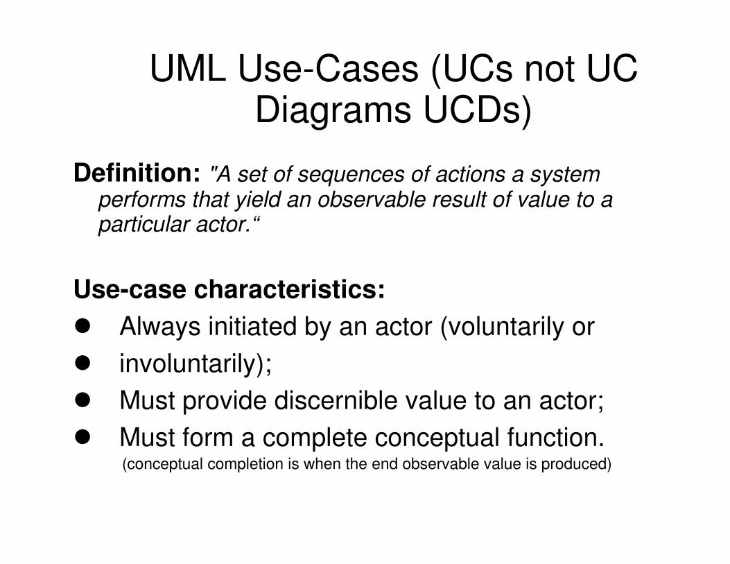
UML Use-Cases (UCs not UC Diagrams UCDs)
Definition: "A set of sequences of actions a system performs that yield an observable result of value to a particular actor.“
Use-case characteristics:
� Always initiated by an actor (voluntarily or
� involuntarily);
� Must provide discernible value to an actor;
� Must form a complete conceptual function.(conceptual completion is when the end observable value is produced)

UC Description Criteria
Use-Case Number (ID) and Name– actors
– pre- and post-conditions
– invariants
– non-functional requirements
– Behaviour modelled as:- activity diagram/s
- decomposition in smaller UC diagrams
– error-handling and exceptions
– Rules modelled as:- activity diagram/s
– services
– examples, prototypes, etc.
– open questions and contacts
– other diagrams
Use-case
Described by
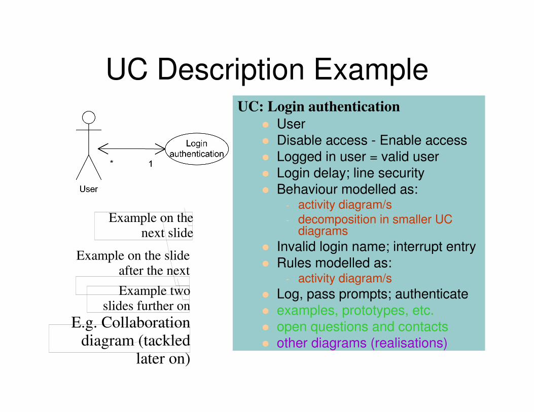
UC Description ExampleUC: Login authentication
� User
� Disable access - Enable access
� Logged in user = valid user
� Login delay; line security
� Behaviour modelled as:- activity diagram/s
- decomposition in smaller UC diagrams
� Invalid login name; interrupt entry
� Rules modelled as:- activity diagram/s
� Log, pass prompts; authenticate
� examples, prototypes, etc.
� open questions and contacts
� other diagrams (realisations)
Example on the next slide
Example on the slide after the next
E.g. Collaboration diagram (tackled
later on)
Example two slides further on

Activity Diagram from previous

Sub-UCs to Login Example

Rules Activity Diagram Example

Consolidating UC Descriptions
Ask yourself these questions:
� Do all actors interacting with a given UC have
communication association to it?
� Are there common roles amongst actors?
� Are there UC similarities?
� Are there special cases of a UC?
� Are all system functions catered for by UCs?
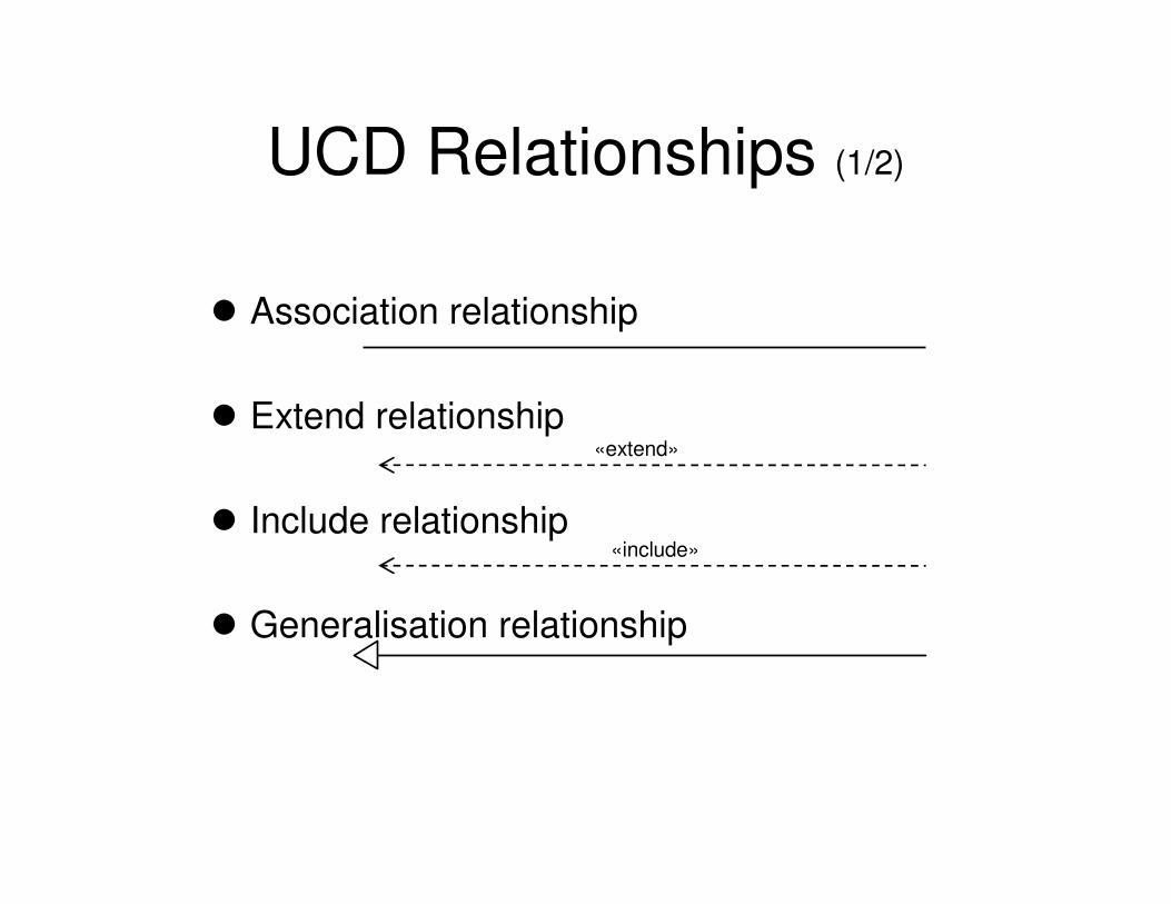
UCD Relationships (1/2)
� Association relationship
� Extend relationship
� Include relationship
� Generalisation relationship
«include»
«extend»

UCD Relationships (2/2)
• Associations• Links actors to their UCs
• Use (or include)• Drawn from base UC to used UC, it shows inclusion of
functionality of one UC in another (used in base)
• Extend• Drawn from extension to base UC, it extends the
meaning of UC to include optional behaviour
• Generalisation• Drawn from specialised UC to base UC, it shows the
link of a specialised UC to a more generalised one
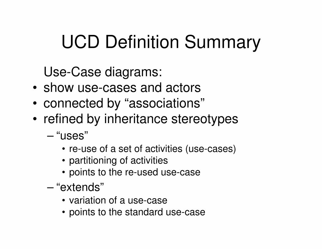
UCD Definition Summary
Use-Case diagrams:• show use-cases and actors• connected by “associations”• refined by inheritance stereotypes
– “uses”• re-use of a set of activities (use-cases)• partitioning of activities• points to the re-used use-case
– “extends”• variation of a use-case• points to the standard use-case

UCD Relationship Example (1/2)

UCD Relationship Example (2/2)
make an
interview
produce a
SRS
elicit customer
needs
«include»
«extend»

What a UCD is - and what it isn’t
� Attention focuser on the part of the business process that is going to be supported by the IS.
� It is the end-user perspective model.
� It is goal driven
� Helps to identify system services.
� Are not used as DFDs.
� Sequences, branching, loops, rules, etc. cannot
(and should not) be directly expressed.
� Are often combined with activity diagrams, which
serve as their refinement.

UCD Case Study (1/3)
Vending Machine
• After client interview the following system scenarios were identified:
• A customer buys a product
• The supplier restocks the machine
• The supplier collects money from the machine
• On the basis of these scenarios, the following three actors can be identified:
• Customer; Supplier; Collector

UCD Case Study (2/3)

UCD Case Study (3/3)
� Introducing annotations (notes) and constraints.
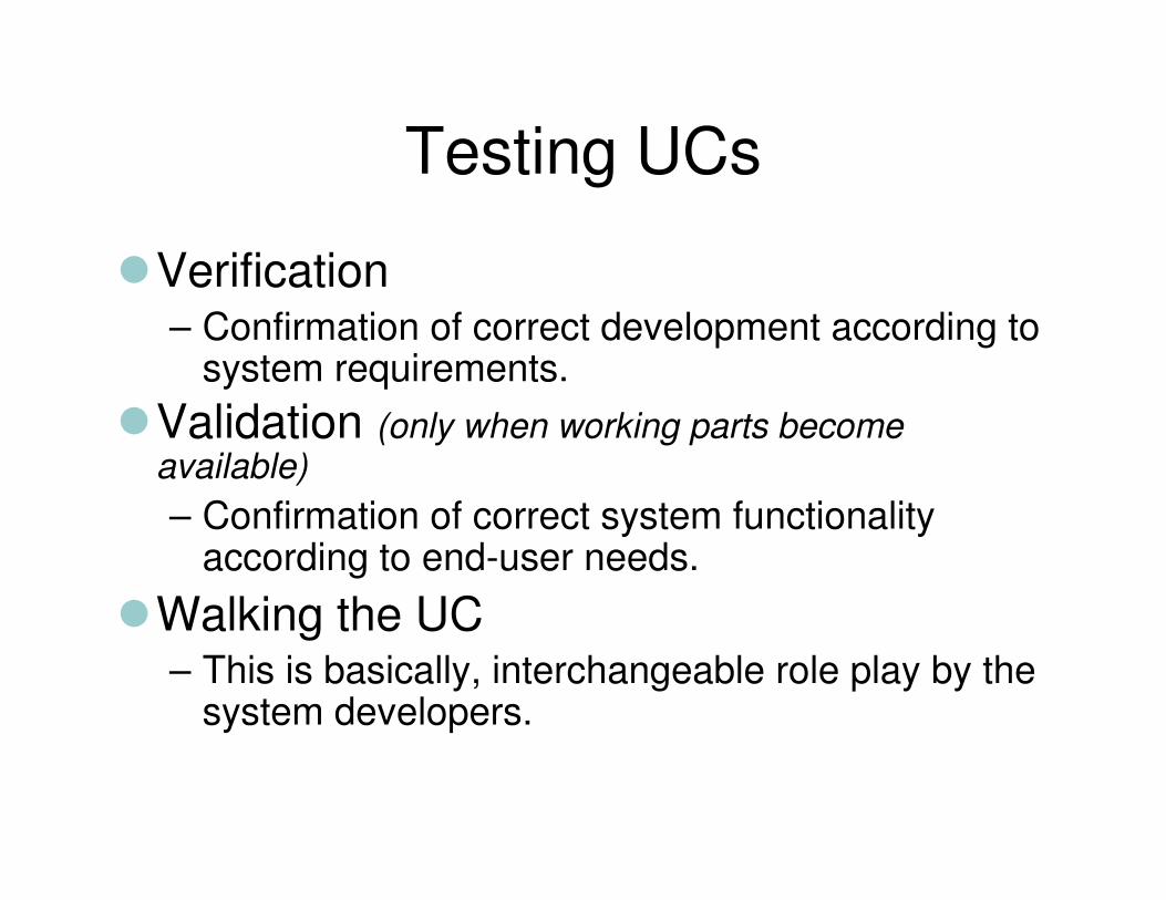
Testing UCs
�Verification– Confirmation of correct development according to
system requirements.
�Validation (only when working parts become available)
– Confirmation of correct system functionality according to end-user needs.
�Walking the UC– This is basically, interchangeable role play by the
system developers.

Workshop Activity -9-
Create a simple UCD (i.e. no “uses” or “extends”relationships) for a course registration system described as follows:
“The course registration system should
allow students to register for and drop
courses. The system’s administrator should
be able to add and delete courses from the
system as well as to cancel planned
courses. If a planned course is cancelled
the relevant instructor should be notified
through the system.”
(Loosely adapted from Lee, 2002)

Workshop Activity -10-
Create a UCD showing UC relationships (i.e. with “uses” or “extends” relationships and any actor generalisations) for an automated medical appointment system described as follows:
“The appointment system should allow new
or existing patients to make medical
appointments according to doctor-
controlled availability schedules.
Medical Centre management should be able
to view current schedule information.”
(Loosely adapted from Dennis, 2002)
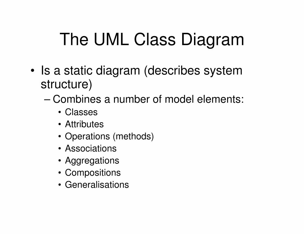
The UML Class Diagram
• Is a static diagram (describes system structure)– Combines a number of model elements:
• Classes
• Attributes
• Operations (methods)
• Associations
• Aggregations
• Compositions
• Generalisations
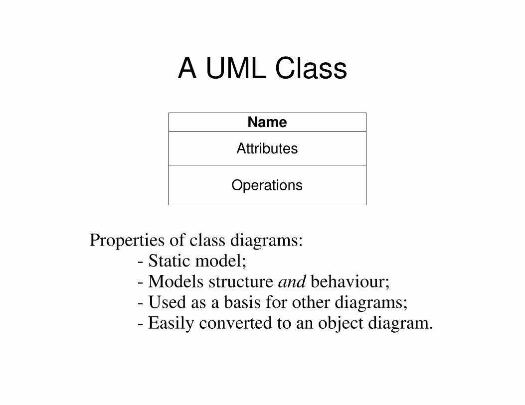
A UML Class
Name
Attributes
Operations
Properties of class diagrams:- Static model;- Models structure and behaviour;- Used as a basis for other diagrams;- Easily converted to an object diagram.

Determining Classes (1/2)
● Is there data that requires storage, transformation or analysis?
● Are there external systems interacting with the one in question?
● Are any class libraries or components being use (from manufacturers, other colleagues or past projects)?
●Does the system handle any devices?
●Does the system model organisational structures?
● Analyse all actor roles.

Determining Classes (2/2)
• Textual Analysis (based on Dennis, 2002)
• A common or improper noun implies a class
• A proper noun or direct reference implies an object (instance of a class)
• A collective noun implies a class made up of groups of objects from another class
• An adjective implies an attribute
• A “doing” verb implies an operation
• A “being” verb implies a classification relationship between an object and its class
• A “having” verb implies an aggregation or association relationship
• A transitive verb implies an operation
• An intransitive verb implies an exception
• A predicate or descriptive verb phrase implies an operation
• An adverb implies an attribute of a relationship or an operation
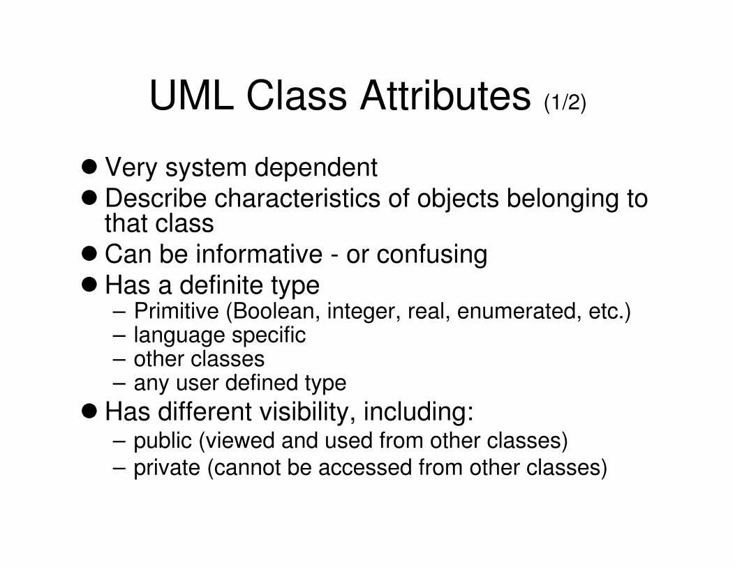
UML Class Attributes (1/2)
� Very system dependent� Describe characteristics of objects belonging to
that class� Can be informative - or confusing� Has a definite type
– Primitive (Boolean, integer, real, enumerated, etc.)– language specific– other classes– any user defined type
� Has different visibility, including:– public (viewed and used from other classes)
– private (cannot be accessed from other classes)

UML Class Attributes (2/2)
• Can be given a default value
• Can be given class-scope
• Can list possible values of enumeration
• Directly implementable into most modern programming languages with object-oriented support (e.g. Java)
Attribute syntax:
Visibility name:type=init_value{property_string}

UML Class Attribute Examples
UNIXaccount+ username : string+ groupname : string+ filesystem_size : integer+ creation_date : date- password : string
UNIXaccount+ username : string+ groupname : string = “staff"+ filesystem_size : integer+ creation_date : date- password : string
Invoice+ amount : real+ date : date = current date+ customer : string+ specification : string- administrator : string = "unspecified"- number_of_invoices : integer
Invoice+ amount : real+ date : date = current date+ customer : string+ specification : string- administrator : string = "unspecified"- number_of_invoices : integer+ status : status = unpaid { unpaid, paid }

UML Class-to-Java Example
Public class UNIXaccount{public string username;public string groupname = "csai";public int filesystem_size;public date creation_date;private string password;static private integer no_of_accounts = 0public UNIXaccount(){//Other initialisationno_of_accounts++;
}//Methods go here
};
UNIXaccount
+ username : string+ groupname : string = “staff"+ filesystem_size : integer+ creation_date : date- password : string- no_of_accounts : integer = 0

Operations (Methods)
Figure
- x : integer = 0
- y : integer = 0
+ draw()
Public class Figure{private int x = 0;private int y = 0;public void draw(){//Java code for drawing figure
}};
Figure fig1 = new Figure();Figure fig2 = new Figure();fig1.draw();fig2.draw();

Constraints on Operations
report ()
BurglarAlarm
isTripped: Boolean = false
PoliceStation
1 station
*
{ if isTrippedthen station.alert(self)}
alert (Alarm)

Association Examples
Person CarDrives � **
Driver Companycar
Person Car**Adult Company
car
EmployeeDrives �1 1
DriverDriver
Person PersonMarried to �
Husband Wife
Domesticappliance
Familymember
⊳·Turns onHeater
·⊳ Cleans
Toaster Dad⊳· Tunes
ChildRadio
Mum

Qualified and "Or" Associations
Person Car*Plates
User PID Process HostIP-addr* *
Item ofclothing
Maleperson
0..*
Femaleperson
0..*{or}
1
1
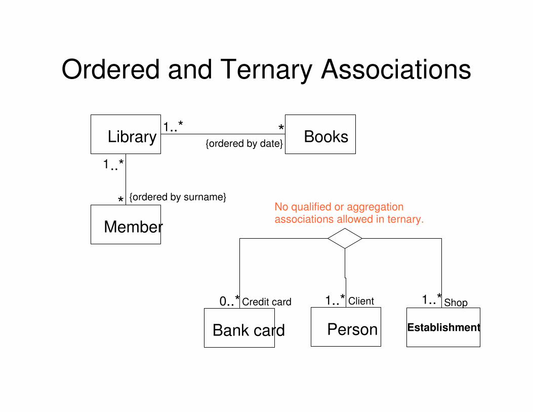
Ordered and Ternary Associations
Library Books*1..*{ordered by date}
Member
{ordered by surname}*
1..*
Person EstablishmentBank card
Client0..*
No qualified or aggregation associations allowed in ternary.
1..*Credit card Shop1..*

Another Ternary Association Example
PlayerT eam
Year
R eco rd
goals forgoals againstw inslosses
goa lkeeper
∗
∗
∗
season
team
ties

Association Classes
Host
Printer1..*
Network
Network adapter
1
*
1
QueueAdapter
Print spooler
Notary
Client Contract
Purchaser Real-estate
Computer

Association by Aggregation

Alternative Notation for Composition Association
Car
Wheels
Body
Engine
Wiring
*
*
*
* Note that association multiplicity is shown within the classes

Roles in Aggregation
Zoo
Mammal Bird
Falcon
Mo
nke
y
Gi ra
f fe0..* 0..* 0..*
ZooMonkey[0..*]: MammalGiraffe[0..*]: MammalHuman[1..*]: MammalFalcon[0..*]: BirdCage[1..*]: Equipment
Equipment
Hum
an 1..* Cage 1..*
My family
Familymember
Ern
est
Fio
na
My familyErnest: Family memberFiona: Family member

Abstract Classes
Abstract Classes and Generalisation Example
Aircraft{abstract}
MakeSeatsEngine type
Start() {abstract}land() {abstract}
Jet plane
MakeSeatsEngine type
Start()land()
Helicopter
MakeSeatsEngine type
Start()land()
Start jet engines
Lower flaps& landing gear
Start blades
Decreaseprop speed
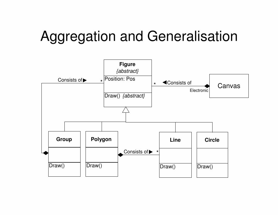
Aggregation and Generalisation
Figure
{abstract}
Position: Pos
Draw() {abstract}
Group
Draw()
Polygon
Draw()
CanvasConsists of*
Electronic
*Consists of
Line
Draw()
Circle
Draw()
Consists of *

Implementing it (e.g. in Java)abstract public class Figure{abstract public void Draw();Pos position;
}public class Group extends Figure{private FigureVector consist_of; public void Draw(){
for (int i = 0; i < consist_of.size(), i++){
consist_of[i].draw();}
}}public class Polygon extends Figure{public void Draw(){
/* something similar to group only using lines instead */
}}
public class Line extends Figure{public void Draw(){
/* code to draw line */}
}public class circle extends Figure{public void Draw(){
/* code to draw circle */}
}

Constrained Generalisations
• Overlapping●A type of inheritance whereby sharing of common
sub-classes by other sub-classes is allowed.
• Disjoint (the default)
●The opposite of overlapping.
• Complete●A type of inheritance whereby the existing sub-
classes are said to fully define a given super-class. No further sub-classing may be defined.
• Incomplete (the default)●Further sub-classes can be added later on to more
concretely specify a given super-class.

Overlapping Generalisation
Electronicdevice
Radioreceiver
Monitorunit
TV set
Amplifier
{overlapping}

Complete Generalisation
Universityfaculty
component
Universitydepartment
Universityinstitute
{complete}
Person
Man Woman
{complete}

Expressing Rules in UML
• Rules are expressed using constraints and derivations●Constraints were mentioned earlier (e.g. or-
associations, ordered associations, inheritance constraints, etc.)
●Derivations are rules governing how entities can be derived (e.g. age = current date - DOB)

Example of Derived Associations
Airport Flight Aircraft
Passenger
Turbo-propaircraft
Jet-turbineaircraft
Uses uses
/1 class passenger
Fixed-wingpassenger craft
Is o
n
NameSurnameAgeNationalityDestinationTicket price/1 class passenger
Passenger
{1 class passenger = = (Ticket price > 400)}
N.B. Relation cardinality is omitted for example clarity
/1 class passenger
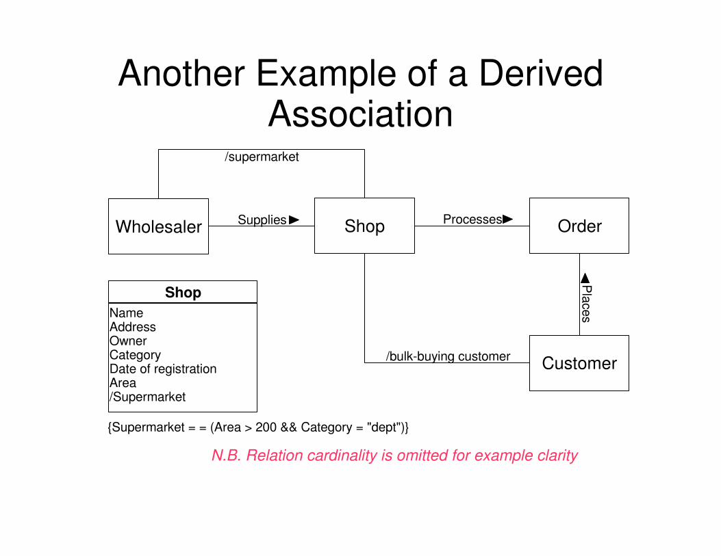
Another Example of a Derived Association
Shop Order
Customer
Processes
/bulk-buying customer
Pla
ces
WholesalerSupplies
/supermarket
NameAddressOwnerCategoryDate of registrationArea/Supermarket
Shop
{Supermarket = = (Area > 200 && Category = "dept")}
N.B. Relation cardinality is omitted for example clarity

Example of a Constraint Association
Database
Organisation
Employee
Entry
in
Member of
{subset}
Main
tain
s
N.B. Relation cardinality is omitted for example clarity
Project manager of

Association Class

Class Dependencies
«friend»ClassA ClassB
ClassC
«instantiate»
«call»
ClassD
operationZ()«friend»
ClassD ClassE
«refine»ClassC combines
two logical classes

Concrete Dependency Example
Co ntroller
D iagramElem ents
D om ainElem ents
G raph icsC ore
«access»
«access»
«access»
«access»
«access»

Class Diagram Example
Element
Carbon Hydrogen
<<covalent>>
<<covalent>>C
C
C H

Instantiation of Class Diagram(in previous slide)
:Carbon :Carbon
:Hydrogen
:Hydrogen
:Hydrogen
:Hydrogen
:Hydrogen:Hydrogen

Another Class Diagram Example
+getOrderStatus+setOrderStatus+getLineItems+setLineItems+getCreditApproved+setCreditApproved...
OrderBean{abstract}
LineItem
{abstract}
Product
1
*
1
*
<<interface>>EntityBean
CreditCard{abstract}
Customer
MyOrder
MyLineItem
MyCreditCard
*
1
*
buyer
order
order
item
item
commodity

Try This Yourselves…
• Create a class diagram to represent a arbitrary interconnection of computers
� Create a class diagram to represent a hierarchical directory system in any OS

CD Case Study (1/3)
Describing the use of a word processor
A user can open a new or existing document. Text is entered through a keyboard. A document is made up of several pages and each page is made up of a header, body and footer. Date, time and page numbermay be added to header or footer. Document body is made up of sentences, which are themselves made up of words and punctuation characters. Words are made up of letters, digits and/or special characters. Pictures and tables may be inserted into the document body. Tables are made up of rows and columns and every cell in a table can contain both text and pictures. Users can save or print documents.

CD Case Study (2/3)
� Nouns (underlined in previous) are either classes or their attributes� Verbs (italicised in previous) are class operations� Main handled entity: document

CD Case Study (3/3)

Some Points to Ponder1. Give two examples to distinguish between aggregation
and composition.2. Explain the concept of an abstract class – give one
example.3. When do you think the use of generalisation is not
justified in model building?4. Link in a class diagram with generalisation the classes:
“Campaign”, “Advert”, “Newspaper advert”, “Magazine advert”, “Advert copy”, “Advert graphic”, and “Advert photograph”.
5. Draw a class diagram for the following classes:● Film (title; producer; length; director; genre)● Ticket (price; adult/child; show time; film)● Patron (name; adult/child; DOB)
6. Link the classes in (5) through message passing and services offered for any one scenario of your choice.

Workshop Activity -11-
Draw a CD for a patient billing system. Include only the attributes that would be appropriate for the system’s context.
Patient (name, gender, address, ID, tel., DOB, blood type, occupation, pass-times, adverse habits, insurance carrier, dietary preferences)
Doctor (name, category, specialist, warrant No., preferred sport, address, tel., DOB, weekly income, VAT No.)
Insurance carrier (date of establishment, name, registration ID, company staff size, address, tel., contact person name)
Create two object diagrams (ODs) based on the CD you develop.

UML Interfaces
• Interfaces are associated with supporting model elements (package, component, class).
• Act as contact points between collaborating model elements and/or their clusters.
• Equivalent to such programming structures as OLE/COM or Java interfaces.
• An interface is abstractly defined.
• An interface is composed of signatures, that as a whole, specify the behaviour of a model element.

UML Interface Example
Political
party
Politician
Voter
Support
Membership
Vote
Representation
PedestalW
ork
Consider() {abstract}
Attend() {abstract}
Donate() {abstract}
Canvass() {abstract}
«interface»
Support
{abstract}
Improve() {abstract}
Fight() {abstract}
Report() {abstract}
«interface»
Work
{abstract}
Lob
by

UML Interface Specialisation
• Interfaces are subject to inheritance in the same way as classes are. Interface inheritance can be shown on a class diagram.
VoterSupport
Floating
voter WeakSupport
Block
voterRegularSupport
Activist
voter StrongSupport
N.B. Only one interface is shown for example clarity
For class specifications
see next slide.

UML Interface Classes (based on
previous example)
Consider() {abstract}
«interface»
WeakSupport
{abstract}
Consider() {abstract}
Attend() {abstract}
«interface»
RegularSupport
{abstract}
Consider() {abstract}
Attend() {abstract}
Donate() {abstract}
Canvass() {abstract}
«interface»
StrongSupport
{abstract}
Please note, that whether regular support should includeeither party activity attendance or the donation of funds(or indeed both) is something of which I haven't thevaguest idea. It is, however, irrelevant to this example.

UML Packages
• Can be considered as a general purpose grouping mechanism (as opposed to a regular UML diagram)
• May be used to group different types of model elements
• Model elements in a package (group) are taken to be related semantically
• Packages can only be related by dependencies, refinements, or generalisations
• Any one modelling element can be located in only one package (i.e. Packages cannot share model elements)

Examples of UML Packages and their Logical Grouping
Subsystem A External view of a UML package named "Subsystem A"
(out of UML, packages are referred to as a subsystems)
Subsystem A
Subsystem BSubsystem C
Subsystem D
Expanded view of "Subsystem A"
showing that it groups together
three other packages named
"Subsystem B/C/D". Note, that
the name of an expanded
package is indicated in the
package tab. This is another way
of showing composed
aggregation.
Package tab

Examples of Relationships between UML Packages
Subsystem A
Subsystem B Subsystem C
Subsystem D
Subsystem E Subsystem F
Subsystem G
Subsystem B is dependent on C
while Subsystem D is dependent
on both B and G. Subsystems E
and F are specialised from the
generalisation Subsystem D. All
packages are within Subsystem A
except for Subsystem G.

Examples of UML Package Importation
A
B C::D
D
C
E
In the above example, package “B” is dependant on the
Imported package “D” from package “C”.

Even Packages have Faces!
Publishes package behaviourSame symbol as for a class interfaceClasses within the given package then implement the particular interface
A
B C
A
B

Packaging Steps
1. Set the context
2. Cluster classes together based on shared relationships
3. Model clustered classes as a package
4. Identify dependency relationships amongst packages
5. Place dependency relationships between packages

Workshop Activity -12-Package and dependency-link the classes in the following system:
Assuming that an automated medical appointment system is to be partitioned as:
• HCI layer
• Problem Definition layer
• Data Management layer
Furthermore, system classes are identified as:• Patient UI
• Appointment UI
• Patient management
• Appointment management
• Patient data management
• Appointment data management
• Patient DB
• Appointment DB

Workshop Activity -13-
Package the UCs of a HL UCD modelling the functionality of an Internet Banking system. The system may be real or hypothetical. Include dependency relationships in your diagram.

• Usually associated to classes and define their behaviour according to the current state of their objects and affecting events.
• Events are taken to be messages, condition
flags, errors or the passage of time.
• UML state diagrams contain at least one starting
point and one end point . However the
latter can be more than one.
• States can have internal variables and activities
associated with them. This information can be
hidden to reduce diagram complexity.
UML State Diagrams

Examples of UML State Diagrams
Off On
Broken
Powersupplied
Externalimpact
Bulbdiscarded
New bulbfitted
Life timeexceeded
Waiting
Registering
Casting
Writing
Deciding
Polling stationopen
On themove
Call
Boothfree
Detailscorrect
Ballot papercomplete
Arriveat booth
Decision taken
Arrive at ballot box
Ballot cast
Vote cast
Ballot paperissued

“Compartments” of a UML State
Name
State variables(optional)
Activities

Standard Events in “Activity Compartment”
• Entry• Specify actions to be taken on entry into the
given state (e.g. Assignment to an attribute or sending a message, etc.)
• Exit• Specify actions to be taken on exit from the
given state (e.g. Run housekeeping program or send message informing of termination, etc.)
• Do• Specify actions to be taken while in the given
state (e.g. Processing data, polling, etc.)

Example of Activity Syntax
login
Login_time = current_time
entry/type "login"exit/send (username, password)do/get usernamedo/get passwordhelp/display help
Note, that actions while in a state, are an on-going process, while events
associated with a transition are stimuli to the triggering of that transition.
Therefore, it is possible that events on transitions act as interrupts to
on-going processes in any given state.

Auto-Triggering of Transitions
• Events can be associated to UML transitions
• UML transitions can be left "event-less"
• If "event-less", then transition triggering in UML becomes dependent on internal state actions
• An "event-less" UML transition will auto-trigger when all its associated internal actions get executed.

Auto-Triggering Examples
Boot
do/run bios
program
Starting OS
do/load OS
Starting
applications
do/load
applications
Select
station
do/read
programme
Tune
radio
do/turn
knob
Listen to
programme
entry/sit
down

UML State Transitions
Full transition syntax is as follows:
event-signature'['guard-condition']/'action-expression'^'send-clause
event-
name'('parameter',',...')'
parameter-name':'type-expression,...
destination-expression'.'destination-event-name'('argument','...')'
The "destination-expression" evaluates to an object or a set of objec
UML Event-Signature Examples
Print_request(pupu:string)
draw(f:figure, c:colour)
redraw
message_received
go_up(floor)
ready
reach_end(section:text_part)

Event-Signature Usage Example
On first floor
Moving up
do/moving to floor
Moving to
first floor
Idle
Moving down
do/moving to floor
Go_up (floor)
ArrivedGo_up (floor)
Go_down (floor)
Arrived
Time-out
Arrived
Activate

UML Guard-Conditions
Is a Boolean expression
Is associated with a UML transition
Is 'AND-ed' with the event-signature (if present)
Control whether a given transition will trigger or not
Examples include:
[t = 15s]
[retries > 3]
withdrawal(amount) [balance >= amount]
read (buff:char) [buff_elements > 0]

Guard-Condition Usage Example
On first floor
Moving up
do/moving to floor
Moving to
first floor
Idle
timer = 0
do/increase timer
Moving down
do/moving to floor
Go_up (floor)
ArrivedGo_up (floor)
Go_down (floor)
Arrived
[timer = time-out]
Arrived
Activate

UML Action-Expressions
• Action-expressions execute when a transition happens
• Not to be confused with internal activities in the activity compartment of a UML state
• Must use parameters existing within the object being modelled by the given state diagram or parameters existing within the associated event-signature
• Zero, one or more action-expressions can be listed per transition using the "/" symbol as delimiter. In the case of more than one, execution is from left to right.
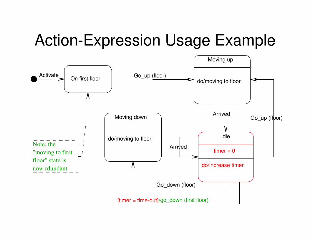
Action-Expression Usage Example
On first floor
Moving up
do/moving to floor
Idle
timer = 0
do/increase timer
Moving down
do/moving to floor
Go_up (floor)
ArrivedGo_up (floor)
Go_down (floor)
[timer = time-out]/go_down (first floor)
Arrived
Activate
Note, the
"moving to first
floor" state is
now rdundant

Multiple Action-Expressions
• Must all appear on the transition arc
• Must be separated by the "/" character
• Are taken to execute in sequence from left to right
• Transition containing only action-expressions are possible (i.e. With no event-signatures and guard-conditions)
• Nested action-expressions are not allowed
• Recursive action-expressions are not allowed

Examples of Multiple Action-Expressions
Receiving packet
packet_cnt ++
entry/init buffer
do/get packet
do/send ack
exit/send ok
Processing packet
ok_packet_cnt ++
entry/init arrays
do/fill data array
do/fill header array
exit/send ok Inc() / separate_parts(data) / length (data)

The Send-Clause
• Also a form of action(-expression)
• Explicitly designed syntax to show message passing
• The destination of the message could be an object or a set of objects
• The destination object can be the object described by the state-diagram itself

Send-Clause Examples
Other examples:out_of_paper() ^indicator.light()request_withdrawal(amount) / show_amount() ^account.debit(amount)left_mouse_btn_down(location) / colour := pick_colour(location) ^pen.set(colour)
Idle
timer = 0
do/increase timer
On first floor[timer = time-out] / go_down(first_floor)
Idle
timer = 0
do/increase timerOn first floor
[timer = time-out] ^ self.go_down(first_floor)
Equivalent transitions

UML Events
UML defines four categories of events:
• A condition becoming true (i.e. A Boolean condition and shown as guard-condition)
• Receipt of an explicit signal, itself an object, from another object (i.e. A message and shown as an event-signature)
• Receipt of a call on an operation by another object (or by the object itself) (i.e. Also a form of message and also shown as an event-signature)
• Passage of a designated period of time (i.e. Time calculation and shown as a time-expression)

Relationship of Events to Class Operations
Display
do/display
current time
Activate Set hours
do/display
hours
Set minutes
do/display
minutes
mode_btn mode_btn
mode_btn
Inc / hours := hours + 1 Inc / hours := minutes + 1
Digital_watch
Activate()De-activate()mode_btn()inc()
Class
De-activate
State Diagram

Example of Signal Class Structuring and Polymorphism
«signal»
Input
{abstract}
Device : Device
Time : Time
«signal»
Mouse
{abstract}
Device : Device
Time : Time
«signal»
Keyboard
Character : Char
Up : Boolean
Down : Boolean
Send
do/send(input)Idle
Input
Done
«signal»
Right_btn
«signal»
Left_btn
In this example, the input signal in the
state diagram on the right could take
the form of any concrete class in the
class hierarchy on the left (i.e. Keyboard,
Right_btn and Left_btn).
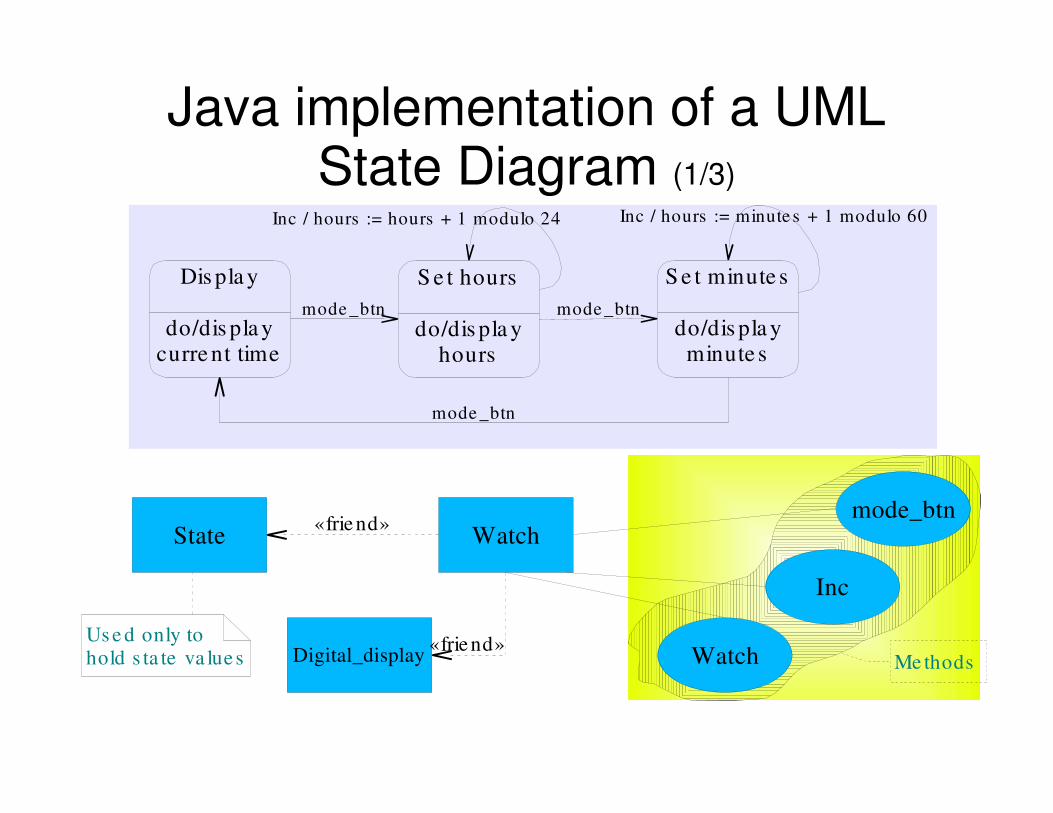
Java implementation of a UML State Diagram (1/3)
Dis pla y
do/dis pla ycurre nt time
S e t hours
do/dis pla yhours
S e t minute s
do/dis pla yminute s
mode _btn mode _btn
mode _btn
Inc / hours := hours + 1 modulo 24 Inc / hours := minute s + 1 modulo 60
State Watch
Watch
mode_btn
Inc
«frie nd»
Me thods
Us e d only tohold s ta te va lue s Digital_display
«frie nd»

Java implementation of a UML State Diagram (2/3)
Public class State
{
public final int Display = 1;
public final int Set_hours = 2;
public final int Set_minutes = 3;
public int value;
}
public class Watch
{
private State state = new State();
private Digital_display LCD = new Digital_display();
public Watch()
{
state.value = State.Display;
LCD.display_time();
}
public void mode_btn()
{
// Cycle through actions depending on current state (see next slide)
}
public void inc()
{
// Update corresponding LCD segments (see next slide)
}
Pleas e note , tha t the class Digita l_displayis omitted to keep the example 's codeshorter and more to the point.

Java implementation of a UML State Diagram (3/3)
// Cycle through actions depending on
// current state (from previous slide)
Public void mode_btn()
{
switch (state.value)
{
case State.Display :
LCD.display_time();
state.value = State.Set_hours;
break;
case State.Set_hours :
LCD.display_hours();
state.value = State.Set_minutes;
break;
case State.minutes :
LCD.display_minutes();
state.value = State.Display;
break;
}
}
// Update corresponding LCD segments
// (from previous slide)
Public void inc()
{
switch (state.value)
{
case State.Display :
;
break;
case State.Set_hours :
LCD.inc_hours();
break;
case State.minutes :
LCD.inc_minutes();
break;
}
}

Messaging between UML State Diagrams
• Used to communicate operations or messages between state diagrams
• Can be implemented by action-expressions (as described earlier) or by dashed arrows
• The Dashed arrows can originate from either a specific state diagram transition or from the state diagram as a whole
• The target state diagram MUST contain the appropriate event-signatures to "catch" any sent messages

Examples of UML State Diagram Messaging (1/2)
I/O Processor
Network adapter
Rece ivingdirect
Rece iving andbuffe ring
Ack()
no_ack()
Idle Proces s ing
Sig() / Ack()
Intr() / no_ack()
Dumpingbuffe r
Ack()
Empty_s ig()
no_ack()

Examples of UML State Diagram Messaging (2/2)
Remote Control
CD Player
Off Idle
Off()
On()
Off On
Off()
On()
P la ying
P la y()
Off()
S top()
P la y()
S top()

UML Sub-States
A mechanism for nesting states
Take the form of "and-sub-states" or "or-sub-states
Tape_winding
Re-winding Fast-forward
Example of anor-sub-state

Examples of "or" and "and" sub-statesFlight_mode
Take-off Cruise
Example of an
or-sub-state
Approach
Video_playback
Forward Backward
Example of an
and-sub-state
Normal Fast

Usage Example of the UML History Indicator (1/2)
Civil-service_career
ClerkExecutive
officer
Administrative
officer
Administrative
assistant
Registration
procedures
Campaign
duties
Result
analysis
enter_politics()
H
[result = negative] / take_up_post()
[result = negative] / resume_career()

Usage Example of the UML History Indicator (2/2)
Install_software
OS Restart_OS
Disk_error
entry/Fix disk
do/Show question dialog
do/Ask alternative
Low_memory
entry/Show question dialog
do/Ask alternative
Disk_error()
H
[alternative = stop]
[alternative = continue]
Restart()
Start install
shield
Install
entry/Ask install
questions
do/Install software
self.Restart()
Restart()
Create()
[alternative = try_again]
out_of_memory()
[alternative = stop]

Workshop Activity -14-
A class named “campaign” is textually described as follows:
“Once a campaign is established, it is assigned a manager and staff. Authorisation in the form of a signed contract and an authorisation code is required to kick-off an established campaign. Once a campaign is started it is noted as active. On completion of an active campaign, accountability is carried out in the form of preparation of final statements. Once payment is received in full, a campaign is considered paid, is archived andany assigned personnel is released. If payment is only effected in part, the campaign is not considered paid but rather simply completed. If any payments were effected in advance of campaign completion and are in excess of the final payment request, a refund should be issued.
Draw a UML state diagram for the above system.

Workshop Activity -15-
One of the states in Workshop Activity -14- will probably be “Active” or “CampaignActive”. Produce a nested state diagram for this state.

UML Sequence Diagrams
• Used to show object interaction
• Interaction takes the form of messages
• Can only model single-scenario situations
• Message type is one of the interaction types (i.e. synchronous, simple, etc. – see next slide)
• Sequence diagrams should be read starting from the top downwards
• Sequence diagrams highlight control focus in objects (i.e. object activation)
• Sequence diagrams can be either of “instance” or of “generic” form

Components of a UML Sequence Diagram
Object:Class
Object name
and “lifeline”
Operation
duration(activation)
Call (synchronisation) message
Independent (asynchronous) messageControl (acknowledgement) message
Undefined type (uncommitted) message
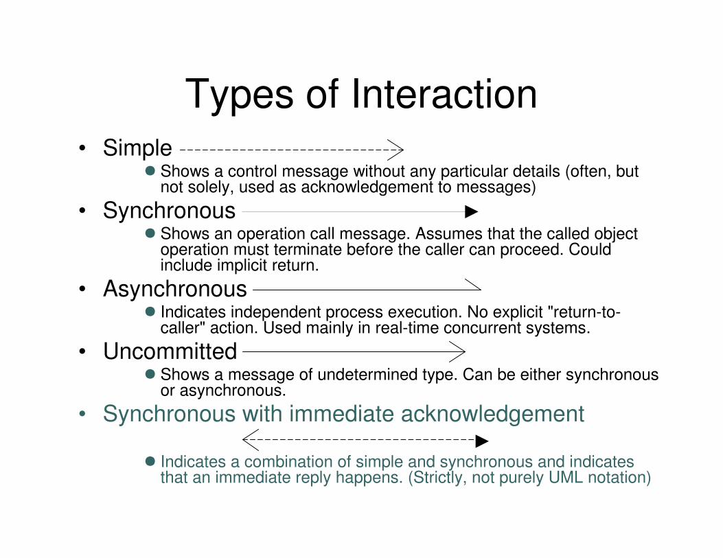
Types of Interaction• Simple
● Shows a control message without any particular details (often, but not solely, used as acknowledgement to messages)
• Synchronous● Shows an operation call message. Assumes that the called object
operation must terminate before the caller can proceed. Could include implicit return.
• Asynchronous● Indicates independent process execution. No explicit "return-to-
caller" action. Used mainly in real-time concurrent systems.
• Uncommitted● Shows a message of undetermined type. Can be either synchronous
or asynchronous.
• Synchronous with immediate acknowledgement
● Indicates a combination of simple and synchronous and indicates that an immediate reply happens. (Strictly, not purely UML notation)
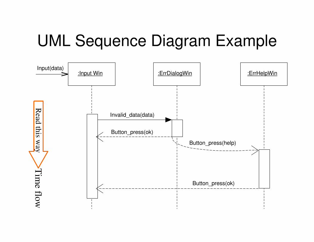
UML Sequence Diagram Example
:ErrDialogWin:Input Win :ErrHelpWin
Invalid_data(data)
Button_press(help)
Button_press(ok)
Button_press(ok)
Input(data)
Read
this w
ayT
ime flo
w

Guidelines for Building a UML Sequence Diagram
1. Set the context (i.e. scope the system)
2. Identify participating objects
3. Draw arbitrary lifelines for each class
4. Draw the duration of the objects on the class lifeline
5. Insert the object messages from top to bottom of diagram (time-based)
6. Check the diagram for completeness

Iteration Conditions in UML Sequence Diagrams
Iteration condition controlled message syntax:[continuationCondition]*operation(parameter)
An example…
: p o lle r : h o s t: lo g in S e s s io n
[ f o r a ll h o s t s ] * re q F re e H o s t ()
re q S t a t u s H o s t 1 ()
[ h o s t 1 N o t F re e ] re q S t a t u s H o s t 2 ()
[ h o s t 2 N o t F re e ] re q S t a t u s H o s t 3 ()

Recursion Modelling in UML Sequence Diagrams
Recursion is always carried out by call(synchronous) messaging and is represented in UMLsequence diagrams as follows:
:F rac talis er
[ for all in tegers in range] * c alc F rac t(int )
:F orm at ter
c alc F rac t (int )
getF rac ta l()

Recursion Example in UML Sequence Diagrams: C o m p u t e r : d r i l lC o n t ro l le r : D r il le r
lo a d F i le ( f i le )
D r i l l ( c o o rd )
in i t S e q ( )
m o v e (o f f s e t )
f in a lS e q ( )
[ w h i le n o t E O F ] * D r il l( c o o rd )

Try this yourself…
Draw up a sequence diagram modelling the case when an advert campaign manager retrieves the details of a particular client’s advertising campaign and lists the details of a particular advert from the campaign. The sequence diagram should also show the case when a new advert is created. Only call messages (synchronous) should be used in this example and use any iteration conditions as you deem necessary.
Objects to use: “CampainManager”, “Client”, “Campaign”, and “Advert”

A Solution to Previous Slide
new Ad:Adv ert
:C lient :C am paign :Adv ert
getC lien tN am e()
[F or a ll c lien t 's c am paigns ] * getC am paignD eta ils ()
lis tAdv erts ()
addN ew Adv ert ()
[F or a ll adv erts in c am paign] *getAdv ertD etails ()
Adv ert ()
:C am paignM anager
lis tC am paigns ()

Try this too…
Create a sequence diagram modelling the behaviour of a PCB drilling machine. The machine will drill holes in a PCB of given dimensions at a set of given co-ordinates. Co-ordinates are given as a list, which must contain at least one set of co-ordinates. Drilling stops when the end of the list is reached or when a user interrupts the process.

A Solution to Previous Slide: C o m p u t e r : d r i l lC o n t ro l le r : D r il le r
lo a d F ile ( f i le )
D r il l( c o o rd )
in it S e q ( )
m o v e (o f f s e t )
f in a lS e q ( )
[ w h i le n o t E O F ] * D r il l( c o o rd )

Object Destruction in UML
:C am paign :Advert
lis tAdverts ()
[ for all adverts ]*getAdvertD etails ()
rem oveAdvert()
delete()
X

Using Labels in UML Sequence Diagrams (1/2)
:BootManager:Computer :OS1
Boot()
Load()
Kernel_down()
Activate()
{max a-b = 8s}
a
b
cd
{max c-d = 1s}
Example of labels specifyingtime constraints. The bootmanager will wait 8 secondsand then boot OS1.

Using Labels in UML Sequence Diagrams (2/2)
:port:Controller :printer
Req()
Query()
Status()
Request()
Send message Req() to
port until status() from
printer is “data_ready”
Ack()Example of labels specifying
iteration. The controller
queries in a cyclic manner the
port for data from the printer.

Other Message Type Examples in UML Sequence Diagram
: d a t a F a r m e r : P r o c e s s o rd a t a I n p u t ( im a g e D a t a )
in i t P r o c ( )
s t a r t G e t 1 ( )
: d a t a R e c e iv e r
s t a r t F a r m ( )
s t a r t G e t 2 ( )
s t a r t G e t 3 ( )
s t a r t G e t 4 ( )
in i t I n p u t S e q ( )

Some Points to Ponder
1. Compare the following term-pairs:State – Behaviour
Class – Object
Action – Activity
Use-case – Scenario
Method – Message
2. Do lifelines always continue down the entire page of a sequence diagram? Explain.
3. What is meant by focus of control in sequence diagrams?
4. What are the essential parts of a sequence diagram message? Give one concrete example.
5. How do synchronous and asynchronous messages differ? Give one concrete example of each case.

Workshop Activity -16-
Assuming that a microwave oven is analysed as the following objects:
• Oven
• Light
• Emission tube
• Timer
The main actions associated with the microwave oven are as follows:
• Opening the door
• Closing the door
• Using the control button
• Completion of the prescribed cooking interval
Create a sequence diagram for the following scenario:– Open the door, insert the food, close the door set the 1-minute
timer, wait for cooking to complete, open the door and retrieve the food.
Create a state diagram for the above scenario.

UML Collaboration Diagram
• Show interactions between collaborating (interacting) objects.
• A bit like a cross between a class and a
sequence diagram (object diagram with
msgs)
• Are mainly a design tool
• Collaboration diagrams are not time-ordered
• Can serve as basis for a sequence diagram
• Like sequence diagrams, collaboration
diagrams employ message passing.

Basic Components of a UML Collaboration Diagram
Object1:ClassA
service
Service:Sequence-number:[condition]:message(parameter)
A return value can be shown as an assigned “:=“ expression
Sequence-number is a decimalised value (e.g. 1, 1.3, 2.3.1, etc.)

Collaboration Diagram Messages
Syntax is:predecessor guard sequence return-value:=signature
Comma-separated list of message path numbers
A condition clause
An integer (sometimes with a trailing letter) followed by a recurrence
Variable
An operation call

Examples of Collaboration Diagram Messages
1:display()
[mode=display]1.2.1:redraw()
[balance > 0]5:debit(amount)
2*[n:=1..m]curr:=nextSeq(n)
2.3[x<0]:doodle()
3.1[y=>]:write()
1.1a,1.1b:doMore()
2.2a,2.2b/3:playback()

Predefined Stereotyped Links in Collaboration Diagrams
• Global• (link role) Instance is available as a name known throughout the system
• Local• (link role) Instance is available as a local variable in an operation
• Parameter• (link role) Instance is available as a parameter in an operation
• Self• (link role) Object can send messages to itself
• Vote• (group of messages) Return value is chosen by majority vote of all
returned values from a given collection
• Broadcast• (group of messages) No message ordering in given group

Collaboration Diagram Object Lifeline Predefined Stereotypes
• New
– Object created during a collaboration
• Destroyed
– Object destroyed during a collaboration
• Transient
– Object created and destroyed during the
same collaboration

UML Collaboration Diagram Example
:Computer
1:Print(ps_file)
:printServer :Printer[printerFree]1.1:Print(ps_file)
Print(ps_file)

UML Collaboration Diagram Example with Return-Value
:Calculator
1*[z:=1..n]:Prim:=nextPrime(prim)
:primModule
calcPrime(n)

Try This Yourself…
• Explain in plain English, what the following collaboration diagram depicts:
:mainWindow:customer
{new}
:customerWindow
{transient}
[free memory]1:Create()
3.1:Update(data)
2:Create()3:Show(customer)
NewCustomer()
{parameter}

…and This One Too Please…
:Button :elevatorControl
:Call {new}
1:getElevator(floor_id)
1.2:Create())
2:next_job=getJob()
Push()
{parameter} job
:Queue
job
1.1*[all queues]:len:=length() {broadcast}
1.3:invoke(job)
:Elevator{local} next_job

Example of Asynchronous Collaboration Diagram
ernest:personkickback()
domestic:coffeeMaker
main:CDplayer
makeCoffee()
play()
ready()

Steps in Building a UML Collaboration Diagram
1. Set the context
2. Identify which objects and which associations between them participate in the collaboration
3. Draw the classes/objects and link them
4. Insert the messages
5. Validate the diagram
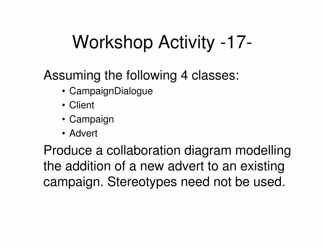
Workshop Activity -17-
Assuming the following 4 classes:• CampaignDialogue
• Client
• Campaign
• Advert
Produce a collaboration diagram modelling the addition of a new advert to an existing campaign. Stereotypes need not be used.

UML Component Diagrams
• Models parts of software and their inter-dependencies
• Represents code structure
• Are generally implemented in physical terms as “files”
• Come as either “source”, “binary”, or “executable” components
• ONLY executable type components can be instantiated

Predefined Component Diagram Stereotypes
• File– Usually a source code file
• Binary / Library– Usually a compiled segment directly linkable into other
compilations
• Executable– Usually a directly executable module
• Table– Usually a database table
• Page– Usually a Web page
• Document– Usually a documentation file (as opposed to compilable code)

Example of a UML Component Diagram

Example of Source Code Dependencies
<<page>>
home.html
<<file>>
aProg.java
<<document>>
aProg.doc
<<document>>
anotherProg.doc
<<file>>
anotherProg.java

Runtime Component Example
<<library>>
comms.dll
<<library>>
graphics.dll
<<library>>
dbgate.dll
<<executable>>
viewer.exe

UML Deployment Diagrams
• Models the run-time architecture (topology) of:
• Processors
• Devices
• Software components
• Is ultimately traceable to initial requirements
Topology
node
Software
component
Classes, objects,
Collab., etc.
Use-case
requirement

Stereotype Examples in Deployment Diagrams
<<printer>>
HP LaserJet 5MP
<<router>>
Cisco X2000
<<carController>>
SAAB 9-5
Navigator

Communication Associations in Deployment Diagrams
NEC PowerMate
i-Select VL4
PC:ClientA
Dell Dimension
2350 PC:ClientB
Silicon Graphics
O2:Server
VAX:DB Server*
*
*
*
* *
<<TCP/IP>>
<<TCP/IP>>
<<DecNet>>
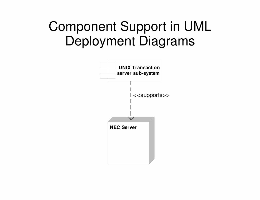
Component Support in UML Deployment Diagrams
NEC Server
UNIX Transaction
server sub-system
<<supports>>

Object Allocation in Deployment Diagrams
Controller:MicrowaveOvenSystem
Guard.exe
Thermometer
controller
<<process>>
Supervisor
Bold object border indicates active object
(i.e. <<process>> or <<thread>>)

Object Transferability in Deployment Diagrams
NEC Server:MainServer
TransactionServ.exe
transf
T1:updateThread
Supervisor
dbobj
callobj
myMachine:ClientPC
ClientProg,exe
transf
<<becomes>>

Deployment Diagrams in the form of Class Diagrams

The End
THANK YOU ALL FOR YOUR TIME AND EFFORT


![[UML] UML, Metodologias e Ferramentas CASE us](https://static.fdocuments.net/doc/165x107/5571f34149795947648dbd59/uml-uml-metodologias-e-ferramentas-case-us.jpg)