UMC Code Comparison - NNICC.orgnnicc.org/wp-content/uploads/2018/02/UMC-Code-Comparison.pdf ·...
79
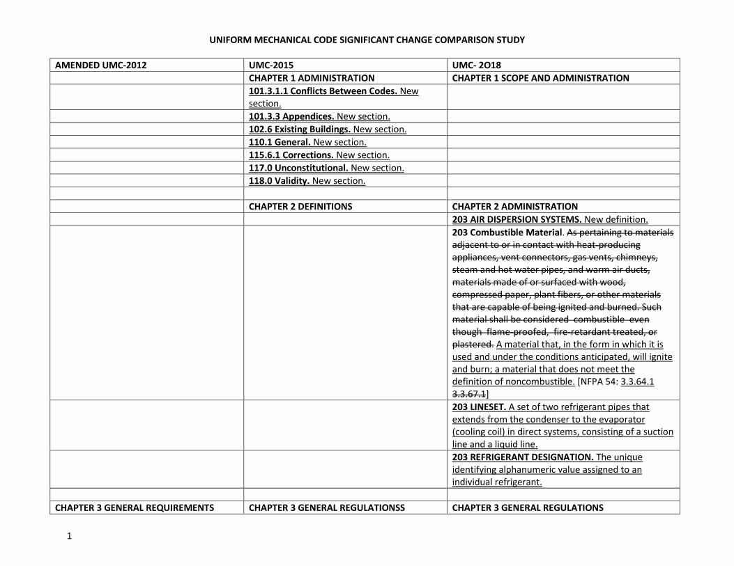
UNIFORM MECHANICAL CODE SIGNIFICANT CHANGE COMPARISON STUDY 1 AMENDED UMC-2012 UMC-2015 UMC- 2O18 CHAPTER 1 ADMINISTRATION CHAPTER 1 SCOPE AND ADMINISTRATION 101.3.1.1 Conflicts Between Codes. New section. 101.3.3 Appendices. New section. 102.6 Existing Buildings. New section. 110.1 General. New section. 115.6.1 Corrections. New section. 117.0 Unconstitutional. New section. 118.0 Validity. New section. CHAPTER 2 DEFINITIONS CHAPTER 2 ADMINISTRATION 203 AIR DISPERSION SYSTEMS. New definition. 203 Combustible Material. As pertaining to materials adjacent to or in contact with heat-producing appliances, vent connectors, gas vents, chimneys, steam and hot water pipes, and warm air ducts, materials made of or surfaced with wood, compressed paper, plant fibers, or other materials that are capable of being ignited and burned. Such material shall be considered combustible even though flame-proofed, fire-retardant treated, or plastered. A material that, in the form in which it is used and under the conditions anticipated, will ignite and burn; a material that does not meet the definition of noncombustible. [NFPA 54: 3.3.64.1 3.3.67.1] 203 LINESET. A set of two refrigerant pipes that extends from the condenser to the evaporator (cooling coil) in direct systems, consisting of a suction line and a liquid line. 203 REFRIGERANT DESIGNATION. The unique identifying alphanumeric value assigned to an individual refrigerant. CHAPTER 3 GENERAL REQUIREMENTS CHAPTER 3 GENERAL REGULATIONSS CHAPTER 3 GENERAL REGULATIONS
Transcript of UMC Code Comparison - NNICC.orgnnicc.org/wp-content/uploads/2018/02/UMC-Code-Comparison.pdf ·...
UNIFORM MECHANICAL CODE SIGNIFICANT CHANGE COMPARISON STUDY
1
AMENDED UMC-2012 UMC-2015 UMC- 2O18
CHAPTER 1 ADMINISTRATION CHAPTER 1 SCOPE AND ADMINISTRATION
101.3.1.1 Conflicts Between Codes. New
section.
101.3.3 Appendices. New section.
102.6 Existing Buildings. New section.
110.1 General. New section.
115.6.1 Corrections. New section.
117.0 Unconstitutional. New section.
118.0 Validity. New section.
CHAPTER 2 DEFINITIONS CHAPTER 2 ADMINISTRATION
203 AIR DISPERSION SYSTEMS. New definition.
203 Combustible Material. As pertaining to materials
adjacent to or in contact with heat-producing
appliances, vent connectors, gas vents, chimneys,
steam and hot water pipes, and warm air ducts,
materials made of or surfaced with wood,
compressed paper, plant fibers, or other materials
that are capable of being ignited and burned. Such
material shall be considered combustible even
though flame-proofed, fire-retardant treated, or
plastered. A material that, in the form in which it is
used and under the conditions anticipated, will ignite
and burn; a material that does not meet the
definition of noncombustible. [NFPA 54: 3.3.64.1
3.3.67.1]
203 LINESET. A set of two refrigerant pipes that
extends from the condenser to the evaporator
(cooling coil) in direct systems, consisting of a suction
line and a liquid line.
203 REFRIGERANT DESIGNATION. The unique
identifying alphanumeric value assigned to an
individual refrigerant.
CHAPTER 3 GENERAL REQUIREMENTS CHAPTER 3 GENERAL REGULATIONSS CHAPTER 3 GENERAL REGULATIONS
UNIFORM MECHANICAL CODE SIGNIFICANT CHANGE COMPARISON STUDY
2
AMENDED UMC-2012 UMC-2015 UMC- 2O18
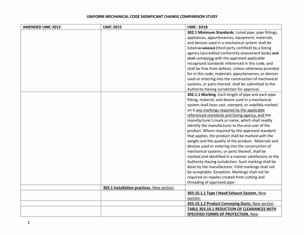
302.1 Minimum Standards. Listed pipe, pipe fittings,
appliances, appurtenances, equipment, materials,
and devices used in a mechanical system shall be
listed or labeled (third party certified) by a listing
agency (accredited conformity assessment body) and
shall complying with the approved applicable
recognized standards referenced in this code, and
shall be free from defects. Unless otherwise provided
for in this code, materials, appurtenances, or devices
used or entering into the construction of mechanical
systems, or parts thereof, shall be submitted to the
Authority Having Jurisdiction for approval.
302.1.1 Marking. Each length of pipe and each pipe
fitting, material, and device used in a mechanical
system shall have cast, stamped, or indelibly marked
on it any markings required by the applicable
referenced standards and listing agency, and the
manufacturer’s mark or name, which shall readily
identify the manufacturer to the end user of the
product. Where required by the approved standard
that applies, the product shall be marked with the
weight and the quality of the product. Materials and
devices used or entering into the construction of
mechanical systems, or parts thereof, shall be
marked and identified in a manner satisfactory to the
Authority Having Jurisdiction. Such marking shall be
done by the manufacturer. Field markings shall not
be acceptable. Exception: Markings shall not be
required on nipples created from cutting and
threading of approved pipe.
303.1 Installation practices. New section.
303.10.1.1 Type I Hood Exhaust System. New
section.
303.10.1.2 Product Conveying Ducts. New section
TABLE 303.10.1 REDUCTION OF CLEARANCES WITH
SPECIFIED FORMS OF PROTECTION. New
UNIFORM MECHANICAL CODE SIGNIFICANT CHANGE COMPARISON STUDY
3
AMENDED UMC-2012 UMC-2015 UMC- 2O18
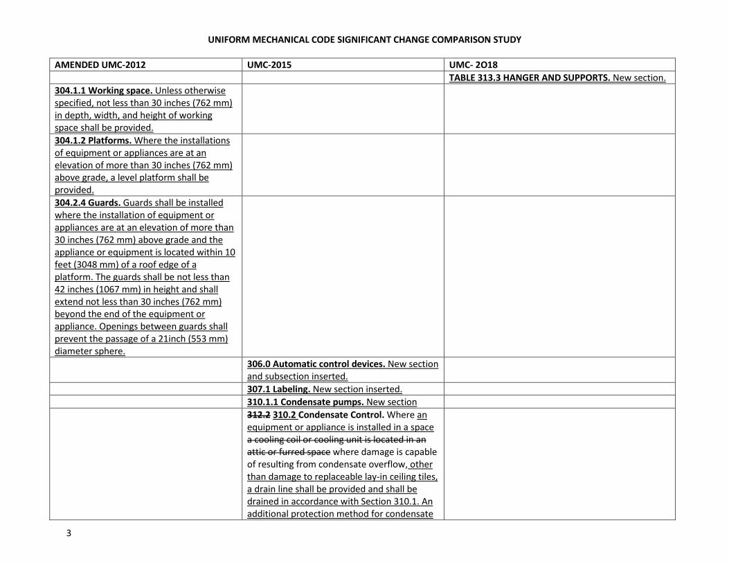
TABLE 313.3 HANGER AND SUPPORTS. New section.
304.1.1 Working space. Unless otherwise
specified, not less than 30 inches (762 mm)
in depth, width, and height of working
space shall be provided.
304.1.2 Platforms. Where the installations
of equipment or appliances are at an
elevation of more than 30 inches (762 mm)
above grade, a level platform shall be
provided.
304.2.4 Guards. Guards shall be installed
where the installation of equipment or
appliances are at an elevation of more than
30 inches (762 mm) above grade and the
appliance or equipment is located within 10
feet (3048 mm) of a roof edge of a
platform. The guards shall be not less than
42 inches (1067 mm) in height and shall
extend not less than 30 inches (762 mm)
beyond the end of the equipment or
appliance. Openings between guards shall
prevent the passage of a 21inch (553 mm)
diameter sphere.
306.0 Automatic control devices. New section
and subsection inserted.
307.1 Labeling. New section inserted.
310.1.1 Condensate pumps. New section
312.2 310.2 Condensate Control. Where an
equipment or appliance is installed in a space
a cooling coil or cooling unit is located in an
attic or furred space where damage is capable
of resulting from condensate overflow, other
than damage to replaceable lay-in ceiling tiles,
a drain line shall be provided and shall be
drained in accordance with Section 310.1. An
additional protection method for condensate
UNIFORM MECHANICAL CODE SIGNIFICANT CHANGE COMPARISON STUDY
4
AMENDED UMC-2012 UMC-2015 UMC- 2O18
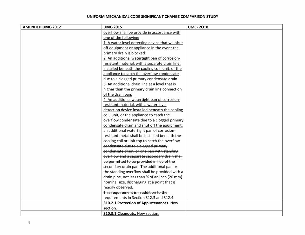
overflow shall be provide in accordance with
one of the following:
1. A water level detecting device that will shut
off equipment or appliance in the event the
primary drain is blocked.
2. An additional watertight pan of corrosion-
resistant material, with a separate drain line,
installed beneath the cooling coil, unit, or the
appliance to catch the overflow condensate
due to a clogged primary condensate drain.
3. An additional drain line at a level that is
higher than the primary drain line connection
of the drain pan.
4. An additional watertight pan of corrosion-
resistant material, with a water level
detection device installed beneath the cooling
coil, unit, or the appliance to catch the
overflow condensate due to a clogged primary
condensate drain and shut off the equipment.
an additional watertight pan of corrosion-
resistant metal shall be installed beneath the
cooling coil or unit top to catch the overflow
condensate due to a clogged primary
condensate drain, or one pan with standing
overflow and a separate secondary drain shall
be permitted to be provided in lieu of the
secondary drain pan. The additional pan or
the standing overflow shall be provided with a
drain pipe, not less than ¾ of an inch (20 mm)
nominal size, discharging at a point that is
readily observed.
This requirement is in addition to the
requirements in Section 312.3 and 312.4.
310.2.1 Protection of Appurtenances. New
section.
310.3.1 Cleanouts. New section.
UNIFORM MECHANICAL CODE SIGNIFICANT CHANGE COMPARISON STUDY
5
AMENDED UMC-2012 UMC-2015 UMC- 2O18
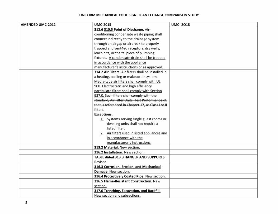
312.6 310.5 Point of Discharge. Air-
conditioning condensate waste piping shall
connect indirectly to the drainage system
through an airgap or airbreak to properly
trapped and vent4ed receptors, dry wells,
leach pits, or the tailpiece of plumbing
fixtures. A condensate drain shall be trapped
in accordance with the appliance
manufacturer’s instructions or as approved.
314.2 Air Filters. Air filters shall be installed in
a heating, cooling or makeup air system.
Media-type air filters shall comply with UL
900. Electrostatic and high efficiency
particulate filters shall comply with Section
937.0. Such filters shall comply with the
standard, Air Filter Units, Test Performance of,
that is referenced in Chapter 17, as Class I or II
filters.
Exceptions:
1. Systems serving single guest rooms or
dwelling units shall not require a
listed filter.
2. Air filters used in listed appliances and
in accordance with the
manufacturer’s instructions.
313.2 Material. New section.
316.2 Installation. New section.
TABLE 316.2 313.3 HANGER AND SUPPORTS.
Revised.
316.3 Corrosion, Erosion, and Mechanical
Damage. New section.
316.4 Protectively Coated Pipe. New section.
316.5 Flame-Resistant Construction. New
section.
317.0 Trenching, Excavation, and Backfill.
New section and subsections.

UNIFORM MECHANICAL CODE SIGNIFICANT CHANGE COMPARISON STUDY
6
AMENDED UMC-2012 UMC-2015 UMC- 2O18
323.0 Installation of Gaseous Hydrogen
Systems. All Hydrogen systems shall comply
with NFPA 2 Chapter 13 Hydrogen
Technology Code, Building Code, and the
Fire Code.
CHAPTER 4 VENITLATION AIR SUPPLY CHAPTER 4 VENITLATION AIR SUPPLY CHAPTER 4 VENITLATION AIR
402.1.3 Ventilation in Health Care Facilities.
New section.
402.2.1 Floor Area to Be Ventilated. New
section.
402.2.1.1 Single Side Opening. New section.
402.2.1.2 Double Side Opening. New section.
402.2.1.3 Corner Openings. New section.
402.2.1.4 Ceiling Height. New section.
402.2 Natural Ventilation.
Exception:
Revise- A mechanical ventilation is not required
where:
(a) Natural ventilation openings comply with the
requirements of Section 402.2 and are
permanently open of have controls that
prevent openings from being closed during
period of expected occupancy, or
(b) The zone is not served by heating or cooling
equipment. [ASHRAE 62:6.4
403.7.1 Alternative Exhaust Ventilation for
Enclosed Parking Garages. Mechanical
ventilation systems for enclosed parking
garages shall be permitted to operate
intermittently where the system is designed
to operate automatically upon detection of
vehicle operation or presence of occupants
by approved automatic detection devices.
UNIFORM MECHANICAL CODE SIGNIFICANT CHANGE COMPARISON STUDY
7
AMENDED UMC-2012 UMC-2015 UMC- 2O18
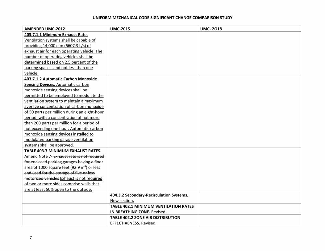
403.7.1.1 Minimum Exhaust Rate.
Ventilation systems shall be capable of
providing 14,000 cfm (6607.3 L/s) of
exhaust air for each operating vehicle. The
number of operating vehicles shall be
determined based on 2.5 percent of the
parking space s and not less than one
vehicle.
403.7.1.2 Automatic Carbon Monoxide
Sensing Devices. Automatic carbon
monoxide sensing devices shall be
permitted to be employed to modulate the
ventilation system to maintain a maximum
average concentration of carbon monoxide
of 50 parts per million during an eight-hour
period, with a concentration of not more
than 200 parts per million for a period of
not exceeding one hour. Automatic carbon
monoxide sensing devices installed to
modulated parking garage ventilation
systems shall be approved.
TABLE 403.7 MINIMUM EXHAUST RATES.
Amend Note 7- Exhaust rate is not required
for enclosed parking garages having a floor
area of 1000 square feet (92.9 m2) or less
and used for the storage of five or less
motorized vehicles Exhaust is not required
of two or more sides comprise walls that
are at least 50% open to the outside.
404.3.2 Secondary-Recirculation Systems.
New section.
TABLE 402.1 MINIMUM VENTILATION RATES
IN BREATHING ZONE. Revised.
TABLE 402.2 ZONE AIR DISTRIBUTION
EFFECTIVENESS. Revised.

UNIFORM MECHANICAL CODE SIGNIFICANT CHANGE COMPARISON STUDY
8
AMENDED UMC-2012 UMC-2015 UMC- 2O18
TABLE 402.7 MINIMUM EXHAUST RATES.
Revised.
CHAPTER 5 EXHAUST SYSTEMS CHAPTER 5 EXHAUST SYSTEMS CHAPTER 5 EXHAUST SYSTEMS
Sections and subsections have been renumbered and
relocated within this Chapter, while the meaning and
concept of the section have remained the same.
501.1 Applicability. This chapter includes
requirements for environmental air ducts,
product-conveying systems, and commercial
hoods and kitchen ventilation. Part I
addresses environmental air ducts and
product-conveying systems. Part II addresses
commercial hoods and kitchen ventilation.
502.0 Termination. New section and
subsections.
503.1 General. Motors and fans shall be sized
to provide the required air movement. Motors
in areas that contain flammable vapors or
dusts shall be of a type approved for such
environments. A manually operated remote
control installed at an approved location shall
be provided to shut off fans or blowers in
flammable vapor or dust systems. Electrical
Equipment used in operations that generate
explosive or flammable vapors, fumes, or
dusts shall be interlocked with the ventilation
system so the equipment cannot be operated
unless the ventilation fans are in operation.
Motors for fans used to convey flammable
vapors or dusts shall be located outside the
duct or shall be protected with approved
shields and dustproofing. Where belts are
used, they shall not enter the duct unless the
belt and pulley within the duct are enclosed.
UNIFORM MECHANICAL CODE SIGNIFICANT CHANGE COMPARISON STUDY
9
AMENDED UMC-2012 UMC-2015 UMC- 2O18
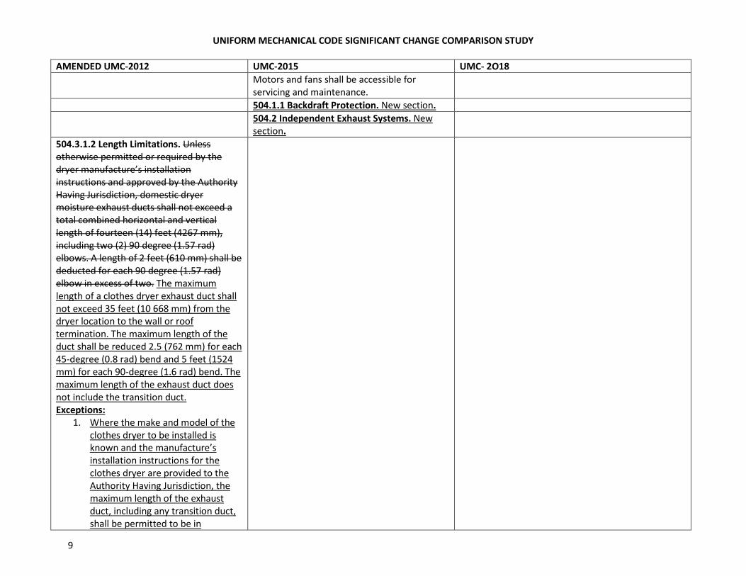
Motors and fans shall be accessible for
servicing and maintenance.
504.1.1 Backdraft Protection. New section.
504.2 Independent Exhaust Systems. New
section.
504.3.1.2 Length Limitations. Unless
otherwise permitted or required by the
dryer manufacture’s installation
instructions and approved by the Authority
Having Jurisdiction, domestic dryer
moisture exhaust ducts shall not exceed a
total combined horizontal and vertical
length of fourteen (14) feet (4267 mm),
including two (2) 90 degree (1.57 rad)
elbows. A length of 2 feet (610 mm) shall be
deducted for each 90 degree (1.57 rad)
elbow in excess of two. The maximum
length of a clothes dryer exhaust duct shall
not exceed 35 feet (10 668 mm) from the
dryer location to the wall or roof
termination. The maximum length of the
duct shall be reduced 2.5 (762 mm) for each
45-degree (0.8 rad) bend and 5 feet (1524
mm) for each 90-degree (1.6 rad) bend. The
maximum length of the exhaust duct does
not include the transition duct.
Exceptions:
1. Where the make and model of the
clothes dryer to be installed is
known and the manufacture’s
installation instructions for the
clothes dryer are provided to the
Authority Having Jurisdiction, the
maximum length of the exhaust
duct, including any transition duct,
shall be permitted to be in
UNIFORM MECHANICAL CODE SIGNIFICANT CHANGE COMPARISON STUDY
10
AMENDED UMC-2012 UMC-2015 UMC- 2O18
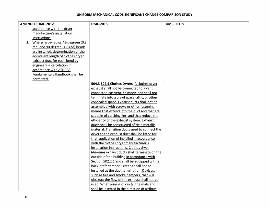
accordance with the dryer
manufacture’s installation
instructions.
2. Where large-radius 45-degreee (0.8
rad) and 90-degree (1.6 rad) bends
are installed, determination of the
equivalent length of clothes dryer
exhaust duct for each bend by
engineering calculation in
accordance with ASHRAE
Fundamentals Handbook shall be
permitted.
504.3 504.4 Clothes Dryers. A clothes dryer
exhaust shall not be connected to a vent
connector, gas vent, chimney, and shall not
terminate into a crawl space, attic, or other
concealed space. Exhaust ducts shall not be
assembled with screws or other fastening
means that extend into the duct and that are
capable of catching lint, and that reduce the
efficiency of the exhaust system. Exhaust
ducts shall be constructed of rigid metallic
material. Transition ducts used to connect the
dryer to the exhaust duct shall be listed for
that application of installed in accordance
with the clothes dryer manufacturer’s
installation instructions. Clothes dryer
Moisture exhaust ducts shall terminate on the
outside of the building in accordance with
Section 502.2.1 and shall be equipped with a
back-draft damper. Screens shall not be
installed at the duct termination. Devices,
such as fire and smoke dampers, that will
obstruct the flow of the exhaust shall not be
used. When joining of ducts, the male end
shall be inserted in the direction of airflow.
UNIFORM MECHANICAL CODE SIGNIFICANT CHANGE COMPARISON STUDY
11
AMENDED UMC-2012 UMC-2015 UMC- 2O18
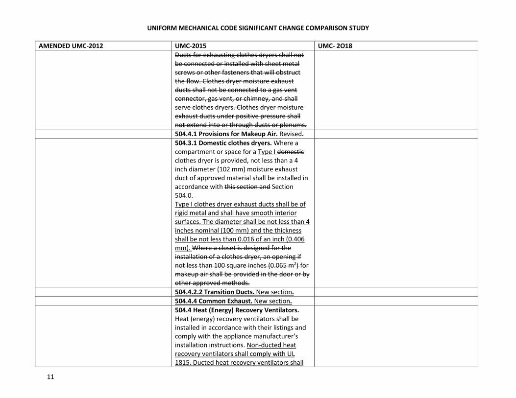
Ducts for exhausting clothes dryers shall not
be connected or installed with sheet metal
screws or other fasteners that will obstruct
the flow. Clothes dryer moisture exhaust
ducts shall not be connected to a gas vent
connector, gas vent, or chimney, and shall
serve clothes dryers. Clothes dryer moisture
exhaust ducts under positive pressure shall
not extend into or through ducts or plenums.
504.4.1 Provisions for Makeup Air. Revised.
504.3.1 Domestic clothes dryers. Where a
compartment or space for a Type I domestic
clothes dryer is provided, not less than a 4
inch diameter (102 mm) moisture exhaust
duct of approved material shall be installed in
accordance with this section and Section
504.0.
Type I clothes dryer exhaust ducts shall be of
rigid metal and shall have smooth interior
surfaces. The diameter shall be not less than 4
inches nominal (100 mm) and the thickness
shall be not less than 0.016 of an inch (0.406
mm). Where a closet is designed for the
installation of a clothes dryer, an opening if
not less than 100 square inches (0.065 m2) for
makeup air shall be provided in the door or by
other approved methods.
504.4.2.2 Transition Ducts. New section.
504.4.4 Common Exhaust. New section.
504.4 Heat (Energy) Recovery Ventilators.
Heat (energy) recovery ventilators shall be
installed in accordance with their listings and
comply with the appliance manufacturer’s
installation instructions. Non-ducted heat
recovery ventilators shall comply with UL
1815. Ducted heat recovery ventilators shall
UNIFORM MECHANICAL CODE SIGNIFICANT CHANGE COMPARISON STUDY
12
AMENDED UMC-2012 UMC-2015 UMC- 2O18
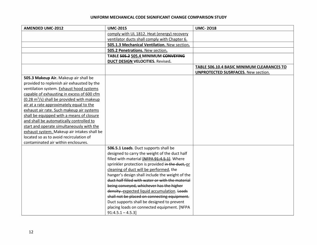
comply with UL 1812. Heat (energy) recovery
ventilator ducts shall comply with Chapter 6.
505.1.3 Mechanical Ventilation. New section.
505.2 Penetrations. New section.
TABLE 505.2 505.4 MINIMUM CONVEYING
DUCT DESIGN VELOCITIES. Revised.
TABLE 506.10.4 BASIC MINIMUM CLEARANCES TO
UNPROTECTED SUSRFACES. New section.
505.3 Makeup Air. Makeup air shall be
provided to replenish air exhausted by the
ventilation system. Exhaust hood systems
capable of exhausting in excess of 600 cfm
(0.28 m3/s) shall be provided with makeup
air at a rate approximately equal to the
exhaust air rate. Such makeup air systems
shall be equipped with a means of closure
and shall be automatically controlled to
start and operate simultaneously with the
exhaust system. Makeup air intakes shall be
located so as to avoid recirculation of
contaminated air within enclosures.
506.5.1 Loads. Duct supports shall be
designed to carry the weight of the duct half
filled with material [NFPA 91:4.5.1]. Where
sprinkler protection is provided in the duct, or
cleaning of duct will be performed, the
hanger’s design shall include the weight of the
duct half filled with water or with the material
being conveyed, whichever has the higher
density. expected liquid accumulation. Loads
shall not be placed on connecting equipment.
Duct supports shall be designed to prevent
placing loads on connected equipment. [NFPA
91:4.5.1 – 4.5.3]
UNIFORM MECHANICAL CODE SIGNIFICANT CHANGE COMPARISON STUDY
13
AMENDED UMC-2012 UMC-2015 UMC- 2O18
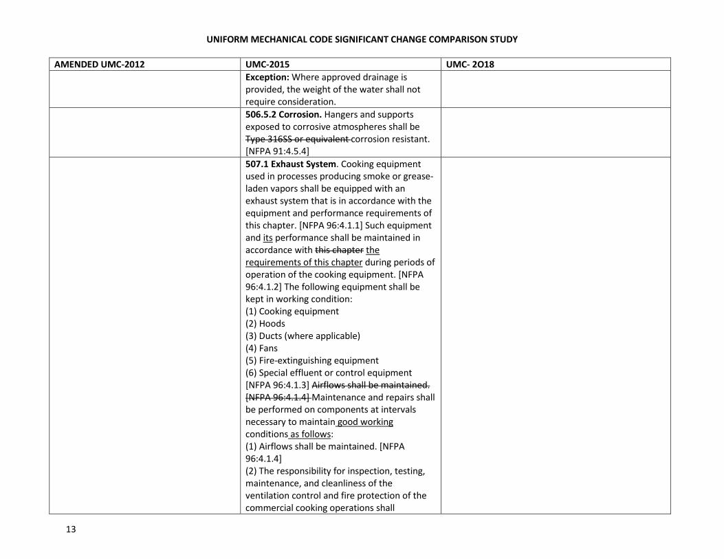
Exception: Where approved drainage is
provided, the weight of the water shall not
require consideration.
506.5.2 Corrosion. Hangers and supports
exposed to corrosive atmospheres shall be
Type 316SS or equivalent corrosion resistant.
[NFPA 91:4.5.4]
507.1 Exhaust System. Cooking equipment
used in processes producing smoke or grease-
laden vapors shall be equipped with an
exhaust system that is in accordance with the
equipment and performance requirements of
this chapter. [NFPA 96:4.1.1] Such equipment
and its performance shall be maintained in
accordance with this chapter the
requirements of this chapter during periods of
operation of the cooking equipment. [NFPA
96:4.1.2] The following equipment shall be
kept in working condition:
(1) Cooking equipment
(2) Hoods
(3) Ducts (where applicable)
(4) Fans
(5) Fire-extinguishing equipment
(6) Special effluent or control equipment
[NFPA 96:4.1.3] Airflows shall be maintained.
[NFPA 96:4.1.4] Maintenance and repairs shall
be performed on components at intervals
necessary to maintain good working
conditions as follows:
(1) Airflows shall be maintained. [NFPA
96:4.1.4]
(2) The responsibility for inspection, testing,
maintenance, and cleanliness of the
ventilation control and fire protection of the
commercial cooking operations shall
UNIFORM MECHANICAL CODE SIGNIFICANT CHANGE COMPARISON STUDY
14
AMENDED UMC-2012 UMC-2015 UMC- 2O18
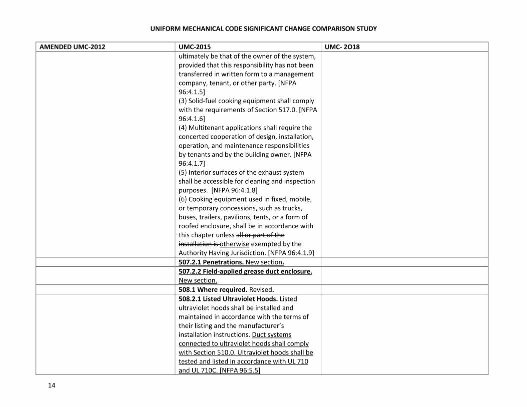
ultimately be that of the owner of the system,
provided that this responsibility has not been
transferred in written form to a management
company, tenant, or other party. [NFPA
96:4.1.5]
(3) Solid-fuel cooking equipment shall comply
with the requirements of Section 517.0. [NFPA
96:4.1.6]
(4) Multitenant applications shall require the
concerted cooperation of design, installation,
operation, and maintenance responsibilities
by tenants and by the building owner. [NFPA
96:4.1.7]
(5) Interior surfaces of the exhaust system
shall be accessible for cleaning and inspection
purposes. [NFPA 96:4.1.8]
(6) Cooking equipment used in fixed, mobile,
or temporary concessions, such as trucks,
buses, trailers, pavilions, tents, or a form of
roofed enclosure, shall be in accordance with
this chapter unless all or part of the
installation is otherwise exempted by the
Authority Having Jurisdiction. [NFPA 96:4.1.9]
507.2.1 Penetrations. New section.
507.2.2 Field-applied grease duct enclosure.
New section.
508.1 Where required. Revised.
508.2.1 Listed Ultraviolet Hoods. Listed
ultraviolet hoods shall be installed and
maintained in accordance with the terms of
their listing and the manufacturer’s
installation instructions. Duct systems
connected to ultraviolet hoods shall comply
with Section 510.0. Ultraviolet hoods shall be
tested and listed in accordance with UL 710
and UL 710C. [NFPA 96:5.5]
UNIFORM MECHANICAL CODE SIGNIFICANT CHANGE COMPARISON STUDY
15
AMENDED UMC-2012 UMC-2015 UMC- 2O18
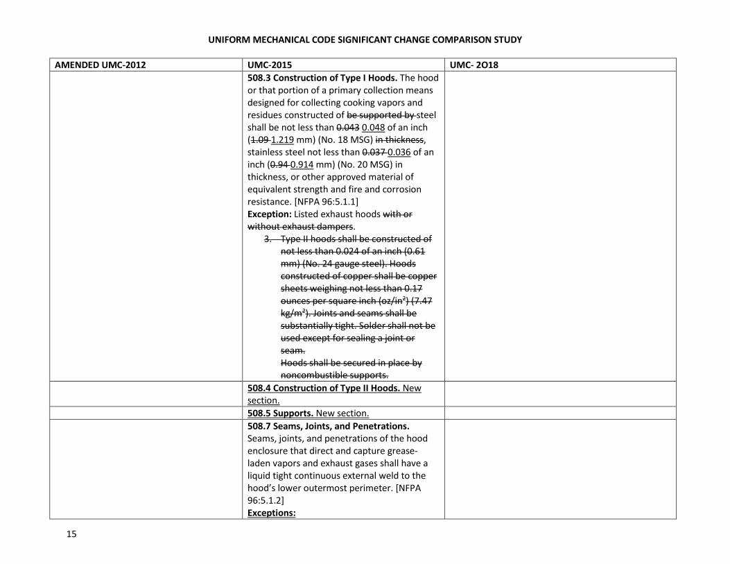
508.3 Construction of Type I Hoods. The hood
or that portion of a primary collection means
designed for collecting cooking vapors and
residues constructed of be supported by steel
shall be not less than 0.043 0.048 of an inch
(1.09 1.219 mm) (No. 18 MSG) in thickness,
stainless steel not less than 0.037 0.036 of an
inch (0.94 0.914 mm) (No. 20 MSG) in
thickness, or other approved material of
equivalent strength and fire and corrosion
resistance. [NFPA 96:5.1.1]
Exception: Listed exhaust hoods with or
without exhaust dampers.
3. Type II hoods shall be constructed of
not less than 0.024 of an inch (0.61
mm) (No. 24 gauge steel). Hoods
constructed of copper shall be copper
sheets weighing not less than 0.17
ounces per square inch (oz/in2) (7.47
kg/m2). Joints and seams shall be
substantially tight. Solder shall not be
used except for sealing a joint or
seam.
Hoods shall be secured in place by
noncombustible supports.
508.4 Construction of Type II Hoods. New
section.
508.5 Supports. New section.
508.7 Seams, Joints, and Penetrations.
Seams, joints, and penetrations of the hood
enclosure that direct and capture grease-
laden vapors and exhaust gases shall have a
liquid tight continuous external weld to the
hood’s lower outermost perimeter. [NFPA
96:5.1.2]
Exceptions:
UNIFORM MECHANICAL CODE SIGNIFICANT CHANGE COMPARISON STUDY
16
AMENDED UMC-2012 UMC-2015 UMC- 2O18
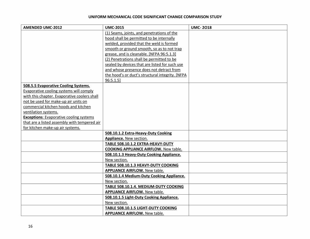
(1) Seams, joints, and penetrations of the
hood shall be permitted to be internally
welded, provided that the weld is formed
smooth or ground smooth, so as to not trap
grease, and is cleanable. [NFPA 96:5.1.3]
(2) Penetrations shall be permitted to be
sealed by devices that are listed for such use
and whose presence does not detract from
the hood’s or duct’s structural integrity. [NFPA
96:5.1.5]
508.5.5 Evaporative Cooling Systems.
Evaporative cooling systems will comply
with this chapter. Evaporative coolers shall
not be used for make-up air units on
commercial kitchen hoods and kitchen
ventilation systems.
Exceptions: Evaporative cooling systems
that are a listed assembly with tempered air
for kitchen make-up air systems.
508.10.1.2 Extra-Heavy-Duty Cooking
Appliance. New section.
TABLE 508.10.1.2 EXTRA-HEAVY-DUTY
COOKING APPLIANCE AIRFLOW. New table.
508.10.1.3 Heavy-Duty Cooking Appliance.
New section.
TABLE 508.10.1.3 HEAVY-DUTY COOKING
APPLIANCE AIRFLOW. New table.
508.10.1.4 Medium-Duty Cooking Appliance.
New section.
TABLE 508.10.1.4. MEDIUM-DUTY COOKING
APPLIANCE AIRFLOW. New table.
508.10.1.5 Light-Duty Cooking Appliance.
New section.
TABLE 508.10.1.5 LIGHT-DUTY COOKING
APPLIANCE AIRFLOW. New table.
UNIFORM MECHANICAL CODE SIGNIFICANT CHANGE COMPARISON STUDY
17
AMENDED UMC-2012 UMC-2015 UMC- 2O18
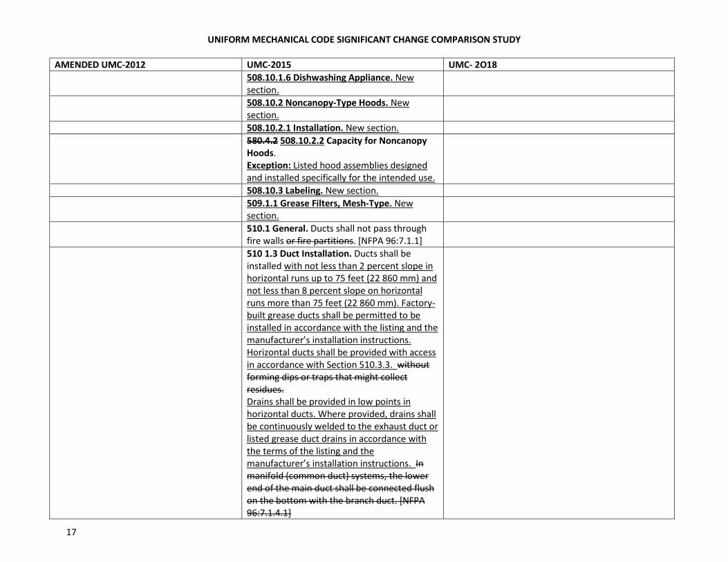
508.10.1.6 Dishwashing Appliance. New
section.
508.10.2 Noncanopy-Type Hoods. New
section.
508.10.2.1 Installation. New section.
580.4.2 508.10.2.2 Capacity for Noncanopy
Hoods.
Exception: Listed hood assemblies designed
and installed specifically for the intended use.
508.10.3 Labeling. New section.
509.1.1 Grease Filters, Mesh-Type. New
section.
510.1 General. Ducts shall not pass through
fire walls or fire partitions. [NFPA 96:7.1.1]
510 1.3 Duct Installation. Ducts shall be
installed with not less than 2 percent slope in
horizontal runs up to 75 feet (22 860 mm) and
not less than 8 percent slope on horizontal
runs more than 75 feet (22 860 mm). Factory-
built grease ducts shall be permitted to be
installed in accordance with the listing and the
manufacturer’s installation instructions.
Horizontal ducts shall be provided with access
in accordance with Section 510.3.3. without
forming dips or traps that might collect
residues.
Drains shall be provided in low points in
horizontal ducts. Where provided, drains shall
be continuously welded to the exhaust duct or
listed grease duct drains in accordance with
the terms of the listing and the
manufacturer’s installation instructions. In
manifold (common duct) systems, the lower
end of the main duct shall be connected flush
on the bottom with the branch duct. [NFPA
96:7.1.4.1]
UNIFORM MECHANICAL CODE SIGNIFICANT CHANGE COMPARISON STUDY
18
AMENDED UMC-2012 UMC-2015 UMC- 2O18
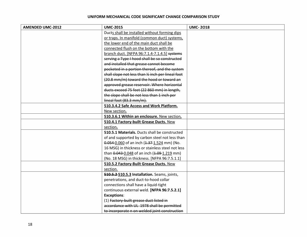
Ducts shall be installed without forming dips
or traps. In manifold (common duct) systems,
the lower end of the main duct shall be
connected flush on the bottom with the
branch duct. [NFPA 96:7.1.4-7.1.4.5] systems
serving a Type I hood shall be so constructed
and installed that grease cannot become
pocketed in a portion thereof, and the system
shall slope not less than ¼ inch per lineal foot
(20.8 mm/m) toward the hood or toward an
approved grease reservoir. Where horizontal
ducts exceed 75 feet (22 860 mm) in length,
the slope shall be not less than 1 inch per
lineal foot (83.3 mm/m).
510.3.4.2 Safe Access and Work Platform.
New section.
510.3.6.1 Within an enclosure. New section.
510.4.1 Factory-built Grease Ducts. New
section.
510.5.1 Materials. Ducts shall be constructed
of and supported by carbon steel not less than
0.054 0.060 of an inch (1.37 1.524 mm) (No.
16 MSG) in thickness or stainless steel not less
than 0.043 0.048 of an inch (1.09 1.219 mm)
(No. 18 MSG) in thickness. [NFPA 96:7.5.1.1]
510.5.2 Factory-Built Grease Ducts. New
section.
510.5.2 510.5.3 Installation. Seams, joints,
penetrations, and duct-to-hood collar
connections shall have a liquid-tight
continuous external weld. [NFPA 96:7.5.2.1]
Exceptions:
(1) Factory-built grease duct listed in
accordance with UL 1978 shall be permitted
to incorporate n on welded joint construction
UNIFORM MECHANICAL CODE SIGNIFICANT CHANGE COMPARISON STUDY
19
AMENDED UMC-2012 UMC-2015 UMC- 2O18
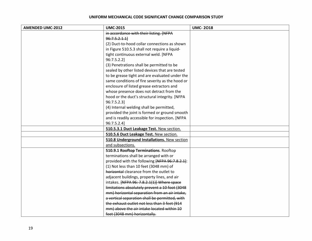
in accordance with their listing. [NFPA
96:7.5.2.1.1]
(2) Duct-to-hood collar connections as shown
in Figure 510.5.3 shall not require a liquid-
tight continuous external weld. [NFPA
96:7.5.2.2]
(3) Penetrations shall be permitted to be
sealed by other listed devices that are tested
to be grease tight and are evaluated under the
same conditions of fire severity as the hood or
enclosure of listed grease extractors and
whose presence does not detract from the
hood or the duct’s structural integrity. [NFPA
96:7.5.2.3]
(4) Internal welding shall be permitted,
provided the joint is formed or ground smooth
and is readily accessible for inspection. [NFPA
96:7.5.2.4]
510.5.3.1 Duct Leakage Test. New section.
510.5.6 Duct Leakage Test. New section.
510.8 Underground Installations. New section
and subsections.
510.9.1 Rooftop Terminations. Rooftop
terminations shall be arranged with or
provided with the following [NFPA 96:7.8.2.1]:
(1) Not less than 10 feet (3048 mm) of
horizontal clearance from the outlet to
adjacent buildings, property lines, and air
intakes. [NFPA 96: 7.8.2.1(1)] Where space
limitations absolutely prevent a 10 foot (3048
mm) horizontal separation from an air intake,
a vertical separation shall be permitted, with
the exhaust outlet not less than 3 feet (914
mm) above the air intake located within 10
feet (3048 mm) horizontally.
UNIFORM MECHANICAL CODE SIGNIFICANT CHANGE COMPARISON STUDY
20
AMENDED UMC-2012 UMC-2015 UMC- 2O18
(2) The exhaust flow directly up and away
from the surface of the roof and not less than
40 inches (1016 mm) above the roof surface.
Not less than 5 feet (1524 mm) of horizontal
clearance from the outlet (fan housing) to a
combustible structure.
(3) A vertical separation of 3 feet (914 mm)
below an exhaust outlet for air intakes within
10 feet (3048 mm) of the exhaust outlet.
(3) The ability to drain grease out of traps or
low points formed in the fan or duct near the
termination of the system into a collection
container that is noncombustible, closed,
rainproof, and structurally sound for the
service to which it is applied, and that will not
sustain combustion. A grease collection device
that is applied to exhaust systems shall not
inhibit the performance of a fan. [NFPA 96:
7.8.2.1(4), 7.8.2.1()5)]
Exception: Grease containers that are
evaluated for equivalency with the preceding
requirements and listed as such.
(5) A grease collection device that is applied to
exhaust systems that does not inhibit the
performance of a fan. (6) A listed grease
collection system that is in accordance with
Section 510.9.1(4) and Section 510.9.1(5).
(7) A listed grease duct in accordance with
Section 507.3.7 or ductwork in accordance
with Section 507.3.8.
(8) A hinged upblast fan supplied with flexible
weatherproof electrical cable and service
hold-open retainer to permit inspection and
cleaning that is listed for commercial cooking
equipment with the following conditions:
UNIFORM MECHANICAL CODE SIGNIFICANT CHANGE COMPARISON STUDY
21
AMENDED UMC-2012 UMC-2015 UMC- 2O18
(a) Where the fan attaches to the ductwork,
the ductwork is not less than 18 inches (457
mm) away from the roof surface, as shown in
Figure 510.9.1.
(b) The fan discharges not less than 40 inches
(1016 mm) away from the roof surface, as
shown in Figure 510.9.1.
(9) Other approved fan, provided it is in
accordance with the following criteria:
(a) The fan is in accordance with the
requirements of Section 510.9.1(3) and
Section 511.1.3.
(b) Its discharge or its extended duct discharge
is in accordance with the requirements of
Section 510.9.1(2). (See Section 511.1.3)
(c) Exhaust fan discharge is directed up and
away from the roof surface. [NFPA 96:7.8.2.1]
510.10 Termination of Type II hood Exhaust
System. New section.
511.1 Exhaust Fans for Commercial Cooking
Operations. Where solid-fuel cooking
equipment is to be vented, the duct system
shall be in accordance with Section 517.0
Exhaust fans shall be installed in accordance
with Section 511.1.1 through Section 511.1.6.
Exhaust fans shall comply with UL 762 and be
installed in accordance with the
manufacturer’s installation instructions.
511.1.4 Construction. Exhaust fan housings
shall be constructed of carbon steel not less
than 0.054 0.060 of an inch (1.37 1.524 mm)
(No. 16 MSG) in thickness, of stainless steel
not less than 0.043 0.048 of an inch (1.09
1.219 mm) (No. 18 MSG) in thickness, or,
where listed, in accordance with the terms of
the listing. [NFPA 96:8.1.45]
UNIFORM MECHANICAL CODE SIGNIFICANT CHANGE COMPARISON STUDY
22
AMENDED UMC-2012 UMC-2015 UMC- 2O18
511.2.2.1 Performance Test. New section.
511.2.2.2 Capture and Containment Test.
New section.
511.2.2.2 Capture and Containment Test. The permit
holder shall verify capture and containment
performance of the Type I hoods. A field test shall be
conducted with the all appliance under the hood at
operating temperatures, with the source of outdoor
air providing makeup air for all the hood operating
and with the source of recirculated air providing
conditioning for the space in which the hood
operating is located at design airflows and with all
sources of replacement air operating at design
airflows for the restaurant. Capture and containment
shall be verified visually by observing smoke or steam
produced by actual or simulated cooking operation or
by simulating cooking using devices such as smoke
candles or smoke puffers. Smoke bombs shall not be
used. [ASHRAE 154:8.2.3 154:8.2]
511.2.3 Operation. A hood exhaust fan(s) shall
continue to operate after the extinguishing
system has been activated, unless fan
shutdown is required by a listed component of
the ventilation system, or by the design of the
extinguishing system. The hood exhaust fan
shall not be required to start upon activation
of the extinguishing system where the exhaust
fan and cooking equipment served by the fan
have been shut down. The exhaust fan shall
be provided with a means so that the fan is
activated when an appliance under the hood
is turned on. [NFPA 96: 8.2.3]
511.2.4 Performance Test. Upon
completion and before final approval of the
installation of a ventilation system serving
commercial food heat-processing
equipment, a performance test shall be
performed to verify the rate of airflow and
UNIFORM MECHANICAL CODE SIGNIFICANT CHANGE COMPARISON STUDY
23
AMENDED UMC-2012 UMC-2015 UMC- 2O18
proper operation as specified in this
chapt4er or manufacturer’s listing. The
permittee shall furnish the necessary test
equipment and devices required to perform
the tests and shall provide the jurisdiction
with an accurate, completed, and signed
test report. The report shall be on a form
containing equivalent information. At the
discretion of the Authority Having
Jurisdiction, the performance teste may be
required to be witnessed by the Authority
Having Jurisdiction, or performed by an
approved third party testing agency.
511.3 Makeup Air. New section.
511.3.1 Air Balance. New section.
513.2.2 Standard. New section.
513.2.5.6 Water Supply. The water required
for listed automatic fire-extinguishing systems
shall be permitted to be supplied from the
domestic water supply where the minimum
water pressure and flow are provided in
accordance with the terms of the listing. The
water supply shall be controlled by a
supervised water supply control valve. Where
the water supply is from a dedicated fire
protection water supply in a building with one
or more fire sprinkler systems, separate
indicating control valves and drains shall be
provided and arranged so that the hood
system and sprinkler system are capable of
being controlled individually. [NFPA 96:10.2.9]
514.2.3 Inspection Tag. The year of
manufacture and the date of installation of
the fusible links shall be marked on the system
inspection tag. The tag shall be signed or
initialed by the installer.

UNIFORM MECHANICAL CODE SIGNIFICANT CHANGE COMPARISON STUDY
24
AMENDED UMC-2012 UMC-2015 UMC- 2O18
Detection devices that are bulb-type
automatic sprinklers and fusible links other
than the metal alloy type shall be examined
and cleaned or replaced annually. [NFPA
96:11.2.5, 11.2.5.1, 11.2.6]
515.1.1 Installation. Listed appliances shall be
installed in accordance with the terms of their
listings and the manufacturer’s installation
instructions. Solid fuel used for flavoring
within a gas-operated appliance shall be in a
solid fuel holder (smoker box) that is listed
with the equipment. [NFPA 96:12.1.2.1,
12.1.2.1.1]
515.1.1.1 Re-evaluation. Cooking appliances
requiring protection shall not be moved,
modified, or rearranged without prior re-
evaluation of the fire extinguishing system by
the system installer or servicing agent, unless
otherwise allowed by the design of the fire-
extinguishing system. A solid fuel holder shall
not be added to an existing appliance until the
fire-extinguishing system has been evaluated
by the fire-extinguishing system service
provider. [NFPA 96:12.1.2.2, 12.1.2.2.1]
517.3.1.1 Equipment with Solid Fuel for
Flavoring. New section.
517.7.6 Fuel Storage. Fuel storage areas shall
be provided with a sprinkler system in
accordance with NFPA 13 except where
permitted in accordance with the following:
(1) Where approved by the Authority Having
Jurisdiction, fuel storage areas shall be
permitted to be protected with a fixed water
pipe system with a hose capable of reaching
all parts of the area.
UNIFORM MECHANICAL CODE SIGNIFICANT CHANGE COMPARISON STUDY
25
AMENDED UMC-2012 UMC-2015 UMC- 2O18
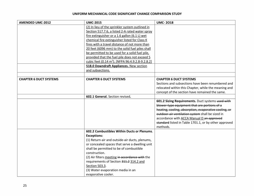
(2) In lieu of the sprinkler system outlined in
Section 517.7.6, a listed 2-A rated water spray
fire extinguisher or a 1.6 gallon (6.1 L) wet
chemical fire extinguisher listed for Class K
fires with a travel distance of not more than
20 feet (6096 mm) to the solid fuel piles shall
be permitted to be used for a solid fuel pile,
provided that the fuel pile does not exceed 5
cubic feet (0.14 m3). [NFPA 96:4.9.2.8-9.2.8.2]
518.0 Downdraft Appliances. New section
and subsections.
CHAPTER 6 DUCT SYSTEMS CHAPTER 6 DUCT SYSTEMS CHAPTER 6 DUCT SYSTEMS
Sections and subsections have been renumbered and
relocated within this Chapter, while the meaning and
concept of the section have remained the same.
602.1 General. Section revised.
601.2 Sizing Requirements. Duct systems used with
blower-type equipment that are portions of a
heating, cooling, absorption, evaporative cooling, or
outdoor-air ventilation system shall be sized in
accordance with ACCA Manual D an approved
standard listed in Table 1701.1, or by other approved
methods.
602.2 Combustibles Within Ducts or Plenums.
Exceptions:
(1) Return-air and outside-air ducts, plenums,
or concealed spaces that serve a dwelling unit
shall be permitted to be of combustible
construction.
(2) Air filters meeting in accordance with the
requirements of Section 311.2 314.2 and
Section 503.3.
(3) Water evaporation media in an
evaporative cooler.
UNIFORM MECHANICAL CODE SIGNIFICANT CHANGE COMPARISON STUDY
26
AMENDED UMC-2012 UMC-2015 UMC- 2O18
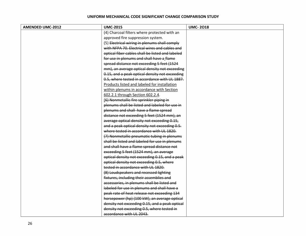
(4) Charcoal filters where protected with an
approved fire suppression system.
(5) Electrical wiring in plenums shall comply
with NFPA 70. Electrical wires and cables and
optical fiber cables shall be listed and labeled
for use in plenums and shall have a flame
spread distance not exceeding 5 feet (1524
mm), an average optical density not exceeding
0.15, and a peak optical density not exceeding
0.5, where tested in accordance with UL 1887.
Products listed and labeled for installation
within plenums in accordance with Section
602.2.1 through Section 602.2.4.
(6) Nonmetallic fire sprinkler piping in
plenums shall be listed and labeled for use in
plenums and shall have a flame spread
distance not exceeding 5 feet (1524 mm), an
average optical density not exceeding 0.15,
and a peak optical density not exceeding 0.5.
where tested in accordance with UL 1820.
(7) Nonmetallic pneumatic tubing in plenums
shall be listed and labeled for use in plenums
and shall have a flame spread distance not
exceeding 5 feet (1524 mm), an average
optical density not exceeding 0.15, and a peak
optical density not exceeding 0.5, where
tested in accordance with UL 1820.
(8) Loudspeakers and recessed lighting
fixtures, including their assemblies and
accessories, in plenums shall be listed and
labeled for use in plenums and shall have a
peak rate of heat release not exceeding 134
horsepower (hp) (100 kW), an average optical
density not exceeding 0.15, and a peak optical
density not exceeding 0.5, where tested in
accordance with UL 2043.
UNIFORM MECHANICAL CODE SIGNIFICANT CHANGE COMPARISON STUDY
27
AMENDED UMC-2012 UMC-2015 UMC- 2O18
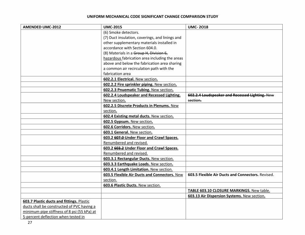
(6) Smoke detectors.
(7) Duct insulation, coverings, and linings and
other supplementary materials installed in
accordance with Section 604.0.
(8) Materials in a Group H, Division 6,
hazardous fabrication area including the areas
above and below the fabrication area sharing
a common air recirculation path with the
fabrication area
602.2.1 Electrical. New section.
602.2.2 Fire sprinkler piping. New section.
602.2.3 Pnuematic Tubing. New section.
602.2.4 Loudspeaker and Recessed Lighting.
New section.
602.2.4 Loudspeaker and Recessed Lighting. New
section.
602.2.5 Discrete Products in Plenums. New
section.
602.4 Existing metal ducts. New section.
602.5 Gypsum. New section.
602.6 Corridors. New section.
603.1 General. New section.
603.2 607.0 Under Floor and Crawl Spaces.
Renumbered and revised.
603.2 603.2 Under Floor and Crawl Spaces.
Renumbered and revised.
603.3.1 Rectangular Ducts. New section.
603.3.3 Earthquake Loads. New section.
603.4.1 Length Limitation. New section.
603.5 Flexible Air Ducts and Connectors. New
section.
603.5 Flexible Air Ducts and Connectors. Revised.
603.6 Plastic Ducts. New section.
TABLE 603.10 CLOSURE MARKINGS. New table.
603.13 Air Dispersion Systems. New section.
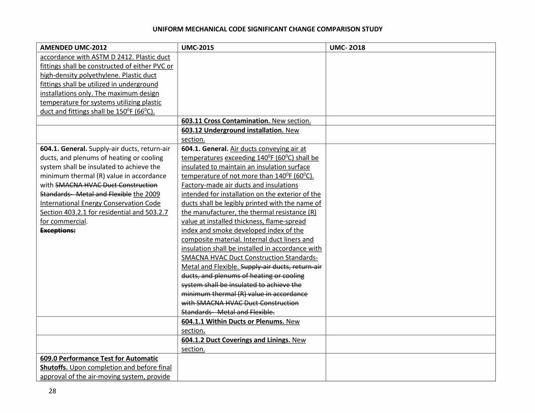
603.7 Plastic ducts and fittings. Plastic
ducts shall be constructed of PVC having a
minimum pipe stiffness of 8 psi (55 kPa) at
5-percent deflection when tested in
UNIFORM MECHANICAL CODE SIGNIFICANT CHANGE COMPARISON STUDY
28
AMENDED UMC-2012 UMC-2015 UMC- 2O18
accordance with ASTM D 2412. Plastic duct
fittings shall be constructed of either PVC or
high-density polyethylene. Plastic duct
fittings shall be utilized in underground
installations only. The maximum design
temperature for systems utilizing plastic
duct and fittings shall be 1500F (660C).
603.11 Cross Contamination. New section.
603.12 Underground installation. New
section.
604.1. General. Supply-air ducts, return-air
ducts, and plenums of heating or cooling
system shall be insulated to achieve the
minimum thermal (R) value in accordance
with SMACNA HVAC Duct Construction
Standards- Metal and Flexible the 2009
International Energy Conservation Code
Section 403.2.1 for residential and 503.2.7
for commercial.
Exceptions:
604.1. General. Air ducts conveying air at
temperatures exceeding 1400F (600C) shall be
insulated to maintain an insulation surface
temperature of not more than 1400F (600C).
Factory-made air ducts and insulations
intended for installation on the exterior of the
ducts shall be legibly printed with the name of
the manufacturer, the thermal resistance (R)
value at installed thickness, flame-spread
index and smoke developed index of the
composite material. Internal duct liners and
insulation shall be installed in accordance with
SMACNA HVAC Duct Construction Standards-
Metal and Flexible. Supply-air ducts, return-air
ducts, and plenums of heating or cooling
system shall be insulated to achieve the
minimum thermal (R) value in accordance
with SMACNA HVAC Duct Construction
Standards- Metal and Flexible.
604.1.1 Within Ducts or Plenums. New
section.
604.1.2 Duct Coverings and Linings. New
section.
609.0 Performance Test for Automatic
Shutoffs. Upon completion and before final
approval of the air-moving system, provide
UNIFORM MECHANICAL CODE SIGNIFICANT CHANGE COMPARISON STUDY
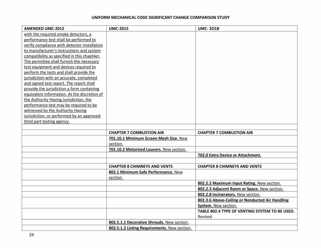
29
AMENDED UMC-2012 UMC-2015 UMC- 2O18
with the required smoke detectors, a
performance test shall be performed to
verify compliance with detector installation
to manufacturer’s instructions and system
compatibility as specified in this chapt4er.
The permittee shall furnish the necessary
test equipment and devices required to
perform the tests and shall provide the
jurisdiction with an accurate, completed
and signed test report. The report shall
provide the jurisdiction a form containing
equivalent information. At the discretion of
the Authority Having Jurisdiction, the
performance test may be required to be
witnessed by the Authority Having
Jurisdiction, or performed by an approved
third part testing agency.
CHAPTER 7 COMBUSTION AIR CHAPTER 7 COMBUSTION AIR
701.10.1 Minimum Screen Mesh Size. New
section.
701.10.2 Motorized Louvers. New section.
702.0 Extra Device or Attachment.
CHAPTER 8 CHIMNEYS AND VENTS CHAPTER 8 CHIMNEYS AND VENTS
802.1 Minimum Safe Performance. New
section.
802.2.2 Maximum Input Rating. New section.
802.2.3 Adjacent Room or Space. New section.
802.2.8 Incinerators. New section.
802.3.6 Above-Ceiling or Nonducted Air Handling
System. New section.
TABLE 802.4 TYPE OF VENTING SYSTEM TO BE USED.
Revised.
802.5.1.1 Decorative Shrouds. New section.
802.5.1.2 Listing Requirements. New section.
UNIFORM MECHANICAL CODE SIGNIFICANT CHANGE COMPARISON STUDY
30
AMENDED UMC-2012 UMC-2015 UMC- 2O18
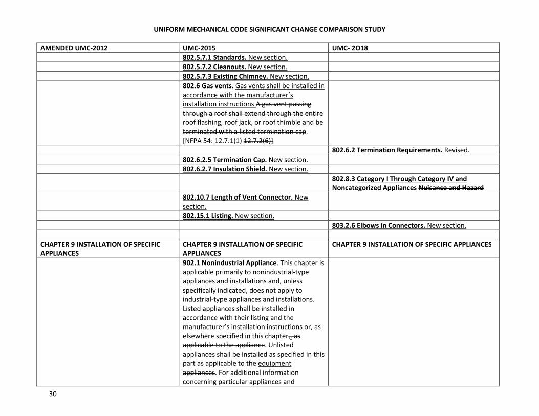
802.5.7.1 Standards. New section.
802.5.7.2 Cleanouts. New section.
802.5.7.3 Existing Chimney. New section.
802.6 Gas vents. Gas vents shall be installed in
accordance with the manufacturer’s
installation instructions A gas vent passing
through a roof shall extend through the entire
roof flashing, roof jack, or roof thimble and be
terminated with a listed termination cap.
[NFPA 54: 12.7.1(1) 12.7.2(6)]
802.6.2 Termination Requirements. Revised.
802.6.2.5 Termination Cap. New section.
802.6.2.7 Insulation Shield. New section.
802.8.3 Category I Through Category IV and
Noncategorized Appliances Nuisance and Hazard
802.10.7 Length of Vent Connector. New
section.
802.15.1 Listing. New section.
803.2.6 Elbows in Connectors. New section.
CHAPTER 9 INSTALLATION OF SPECIFIC
APPLIANCES
CHAPTER 9 INSTALLATION OF SPECIFIC
APPLIANCES
CHAPTER 9 INSTALLATION OF SPECIFIC APPLIANCES
902.1 Nonindustrial Appliance. This chapter is
applicable primarily to nonindustrial-type
appliances and installations and, unless
specifically indicated, does not apply to
industrial-type appliances and installations.
Listed appliances shall be installed in
accordance with their listing and the
manufacturer’s installation instructions or, as
elsewhere specified in this chapter,. as
applicable to the appliance. Unlisted
appliances shall be installed as specified in this
part as applicable to the equipment
appliances. For additional information
concerning particular appliances and
UNIFORM MECHANICAL CODE SIGNIFICANT CHANGE COMPARISON STUDY
31
AMENDED UMC-2012 UMC-2015 UMC- 2O18
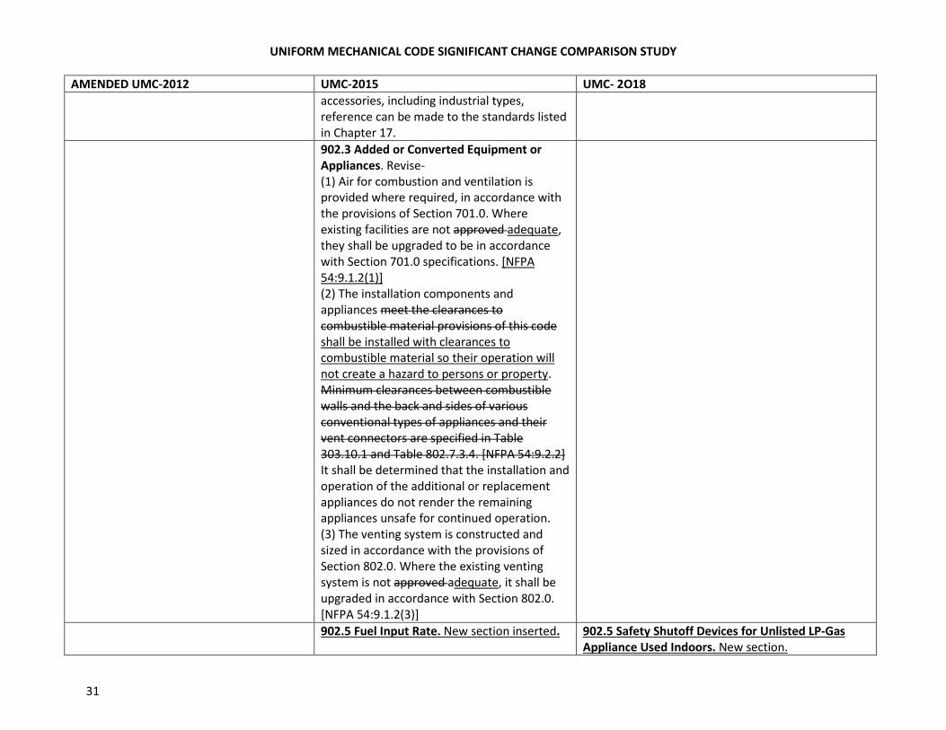
accessories, including industrial types,
reference can be made to the standards listed
in Chapter 17.
902.3 Added or Converted Equipment or
Appliances. Revise-
(1) Air for combustion and ventilation is
provided where required, in accordance with
the provisions of Section 701.0. Where
existing facilities are not approved adequate,
they shall be upgraded to be in accordance
with Section 701.0 specifications. [NFPA
54:9.1.2(1)]
(2) The installation components and
appliances meet the clearances to
combustible material provisions of this code
shall be installed with clearances to
combustible material so their operation will
not create a hazard to persons or property.
Minimum clearances between combustible
walls and the back and sides of various
conventional types of appliances and their
vent connectors are specified in Table
303.10.1 and Table 802.7.3.4. [NFPA 54:9.2.2]
It shall be determined that the installation and
operation of the additional or replacement
appliances do not render the remaining
appliances unsafe for continued operation.
(3) The venting system is constructed and
sized in accordance with the provisions of
Section 802.0. Where the existing venting
system is not approved adequate, it shall be
upgraded in accordance with Section 802.0.
[NFPA 54:9.1.2(3)]
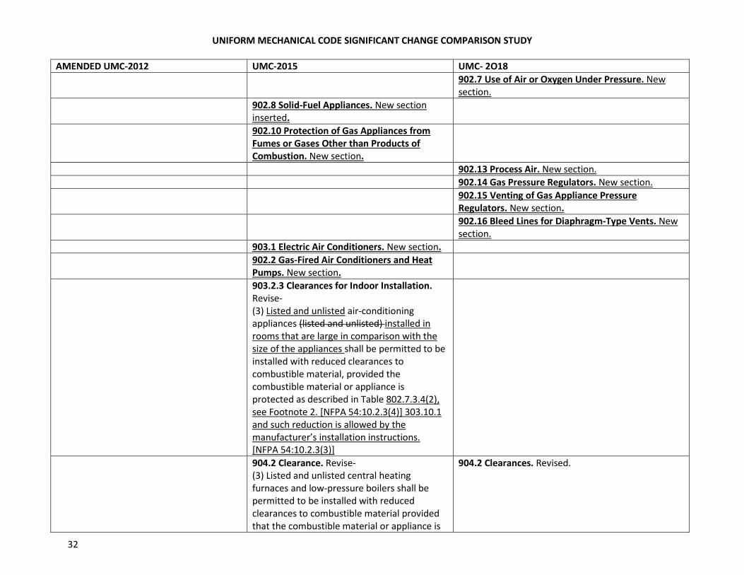
902.5 Fuel Input Rate. New section inserted. 902.5 Safety Shutoff Devices for Unlisted LP-Gas
Appliance Used Indoors. New section.
UNIFORM MECHANICAL CODE SIGNIFICANT CHANGE COMPARISON STUDY
32
AMENDED UMC-2012 UMC-2015 UMC- 2O18
902.7 Use of Air or Oxygen Under Pressure. New
section.
902.8 Solid-Fuel Appliances. New section
inserted.
902.10 Protection of Gas Appliances from
Fumes or Gases Other than Products of
Combustion. New section.
902.13 Process Air. New section.
902.14 Gas Pressure Regulators. New section.
902.15 Venting of Gas Appliance Pressure
Regulators. New section.
902.16 Bleed Lines for Diaphragm-Type Vents. New
section.
903.1 Electric Air Conditioners. New section.
902.2 Gas-Fired Air Conditioners and Heat
Pumps. New section.
903.2.3 Clearances for Indoor Installation.
Revise-
(3) Listed and unlisted air-conditioning
appliances (listed and unlisted) installed in
rooms that are large in comparison with the
size of the appliances shall be permitted to be
installed with reduced clearances to
combustible material, provided the
combustible material or appliance is
protected as described in Table 802.7.3.4(2),
see Footnote 2. [NFPA 54:10.2.3(4)] 303.10.1
and such reduction is allowed by the
manufacturer’s installation instructions.
[NFPA 54:10.2.3(3)]
904.2 Clearance. Revise-
(3) Listed and unlisted central heating
furnaces and low-pressure boilers shall be
permitted to be installed with reduced
clearances to combustible material provided
that the combustible material or appliance is
904.2 Clearances. Revised.
UNIFORM MECHANICAL CODE SIGNIFICANT CHANGE COMPARISON STUDY
33
AMENDED UMC-2012 UMC-2015 UMC- 2O18
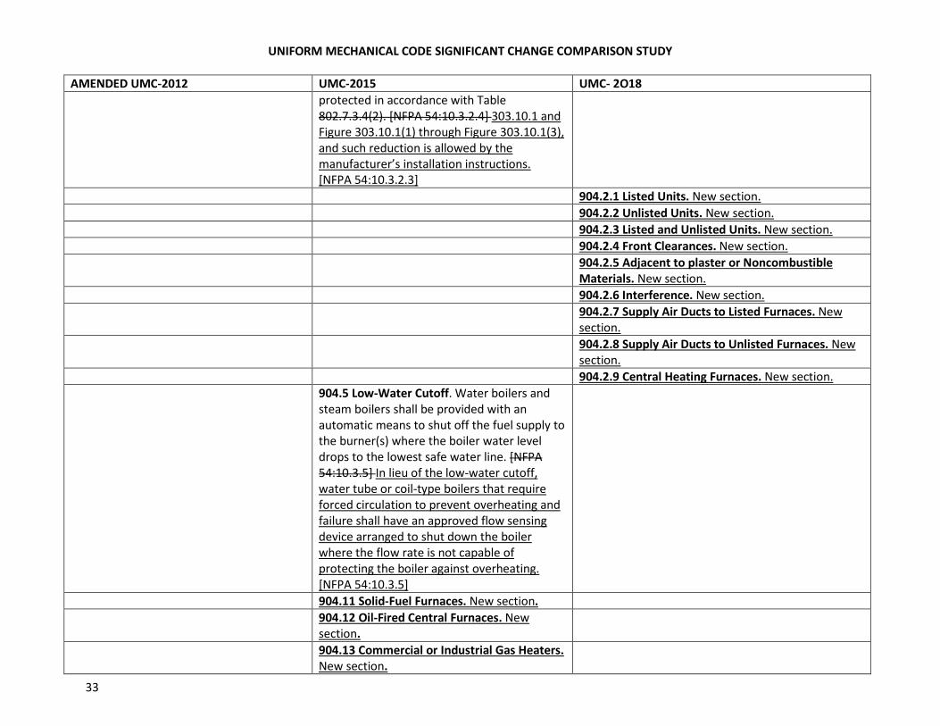
protected in accordance with Table
802.7.3.4(2). [NFPA 54:10.3.2.4] 303.10.1 and
Figure 303.10.1(1) through Figure 303.10.1(3),
and such reduction is allowed by the
manufacturer’s installation instructions.
[NFPA 54:10.3.2.3]
904.2.1 Listed Units. New section.
904.2.2 Unlisted Units. New section.
904.2.3 Listed and Unlisted Units. New section.
904.2.4 Front Clearances. New section.
904.2.5 Adjacent to plaster or Noncombustible
Materials. New section.
904.2.6 Interference. New section.
904.2.7 Supply Air Ducts to Listed Furnaces. New
section.
904.2.8 Supply Air Ducts to Unlisted Furnaces. New
section.
904.2.9 Central Heating Furnaces. New section.
904.5 Low-Water Cutoff. Water boilers and
steam boilers shall be provided with an
automatic means to shut off the fuel supply to
the burner(s) where the boiler water level
drops to the lowest safe water line. [NFPA
54:10.3.5] In lieu of the low-water cutoff,
water tube or coil-type boilers that require
forced circulation to prevent overheating and
failure shall have an approved flow sensing
device arranged to shut down the boiler
where the flow rate is not capable of
protecting the boiler against overheating.
[NFPA 54:10.3.5]
904.11 Solid-Fuel Furnaces. New section.
904.12 Oil-Fired Central Furnaces. New
section.
904.13 Commercial or Industrial Gas Heaters.
New section.
UNIFORM MECHANICAL CODE SIGNIFICANT CHANGE COMPARISON STUDY
34
AMENDED UMC-2012 UMC-2015 UMC- 2O18
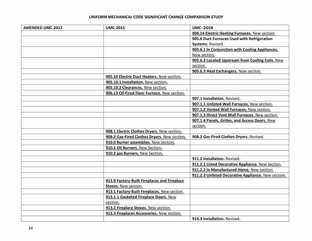
904.14 Electric Heating Furnaces. New section.
905.6 Duct Furnaces Used with Refrigeration
Systems. Revised.
905.6.1 In Conjunction with Cooling Appliances.
New section.
905.6.2 Located Upstream from Cooling Coils. New
section.
905.6.3 Heat Exchangers. New section.
905.10 Electric Duct Heaters. New section.
905.10.1 Installation. New section.
905.10.2 Clearances. New section.
906.13 Oil-Fired Floor Furnace. New section.
907.1 Installation. Revised.
907.1.1 Unlisted Wall Furnaces. New section.
907.1.2 Vented Wall Furnaces. New section.
907.1.3 Direct Vent Wall Furnaces. New section.
907.1.4 Panels, Grilles, and Access Doors. New
section.
908.1 Electric Clothes Dryers. New section.
908.2 Gas-Fired Clothes Dryers. New section. 908.2 Gas-Fired Clothes Dryers. Revised.
910.0 Burner assemblies. New Section.
910.1 Oil Burners. New Section.
910.2 gas Burners. New Section.
911.2 Installation. Revised.
911.2.1 Listed Decorative Appliance. New section.
911.2.2 In Manufactured Home. New section.
911.2.3 Unlisted Decorative Appliance. New section.
913.0 Factory-Built Fireplaces and Fireplace
Stoves. New section.
913.1 Factory-Built Fireplaces. New section.
913.1.1 Gasketed Fireplace Doors. New
section.
913.2 Fireplace Stoves. New section.
913.3 Fireplaces Accessories. New section.
914.3 Installation. Revised.
UNIFORM MECHANICAL CODE SIGNIFICANT CHANGE COMPARISON STUDY
35
AMENDED UMC-2012 UMC-2015 UMC- 2O18
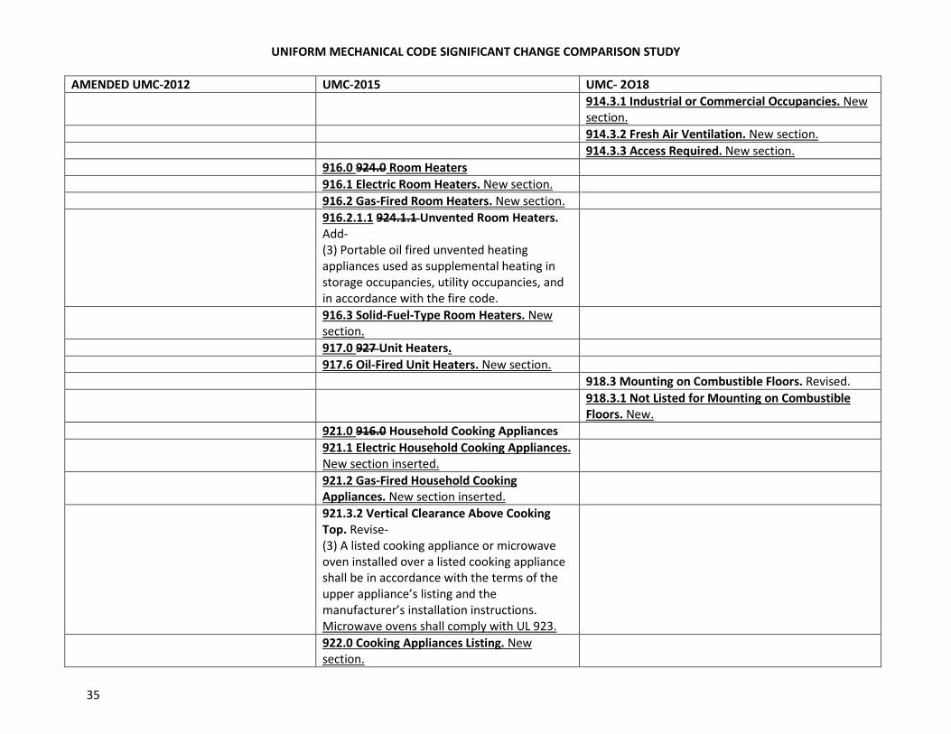
914.3.1 Industrial or Commercial Occupancies. New
section.
914.3.2 Fresh Air Ventilation. New section.
914.3.3 Access Required. New section.
916.0 924.0 Room Heaters
916.1 Electric Room Heaters. New section.
916.2 Gas-Fired Room Heaters. New section.
916.2.1.1 924.1.1 Unvented Room Heaters.
Add-
(3) Portable oil fired unvented heating
appliances used as supplemental heating in
storage occupancies, utility occupancies, and
in accordance with the fire code.
916.3 Solid-Fuel-Type Room Heaters. New
section.
917.0 927 Unit Heaters.
917.6 Oil-Fired Unit Heaters. New section.
918.3 Mounting on Combustible Floors. Revised.
918.3.1 Not Listed for Mounting on Combustible
Floors. New.
921.0 916.0 Household Cooking Appliances
921.1 Electric Household Cooking Appliances.
New section inserted.
921.2 Gas-Fired Household Cooking
Appliances. New section inserted.
921.3.2 Vertical Clearance Above Cooking
Top. Revise-
(3) A listed cooking appliance or microwave
oven installed over a listed cooking appliance
shall be in accordance with the terms of the
upper appliance’s listing and the
manufacturer’s installation instructions.
Microwave ovens shall comply with UL 923.
922.0 Cooking Appliances Listing. New
section.
UNIFORM MECHANICAL CODE SIGNIFICANT CHANGE COMPARISON STUDY
36
AMENDED UMC-2012 UMC-2015 UMC- 2O18
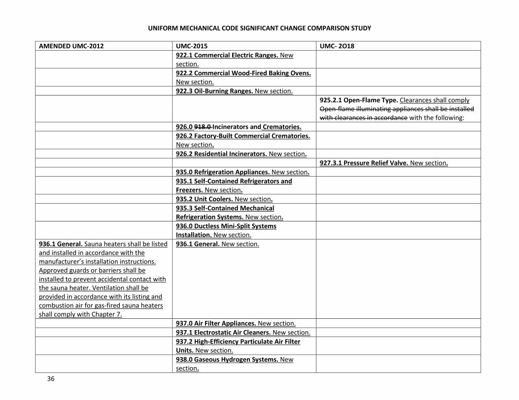
922.1 Commercial Electric Ranges. New
section.
922.2 Commercial Wood-Fired Baking Ovens.
New section.
922.3 Oil-Burning Ranges. New section.
925.2.1 Open-Flame Type. Clearances shall comply
Open-flame illuminating appliances shall be installed
with clearances in accordance with the following:
926.0 918.0 Incinerators and Crematories.
926.2 Factory-Built Commercial Crematories.
New section.
926.2 Residential Incinerators. New section.
927.3.1 Pressure Relief Valve. New section.
935.0 Refrigeration Appliances. New section.
935.1 Self-Contained Refrigerators and
Freezers. New section.
935.2 Unit Coolers. New section.
935.3 Self-Contained Mechanical
Refrigeration Systems. New section.
936.0 Ductless Mini-Split Systems
Installation. New section.
936.1 General. Sauna heaters shall be listed
and installed in accordance with the
manufacturer’s installation instructions.
Approved guards or barriers shall be
installed to prevent accidental contact with
the sauna heater. Ventilation shall be
provided in accordance with its listing and
combustion air for gas-fired sauna heaters
shall comply with Chapter 7.
936.1 General. New section.
937.0 Air Filter Appliances. New section.
937.1 Electrostatic Air Cleaners. New section.
937.2 High-Efficiency Particulate Air Filter
Units. New section.
938.0 Gaseous Hydrogen Systems. New
section.
UNIFORM MECHANICAL CODE SIGNIFICANT CHANGE COMPARISON STUDY
37
AMENDED UMC-2012 UMC-2015 UMC- 2O18
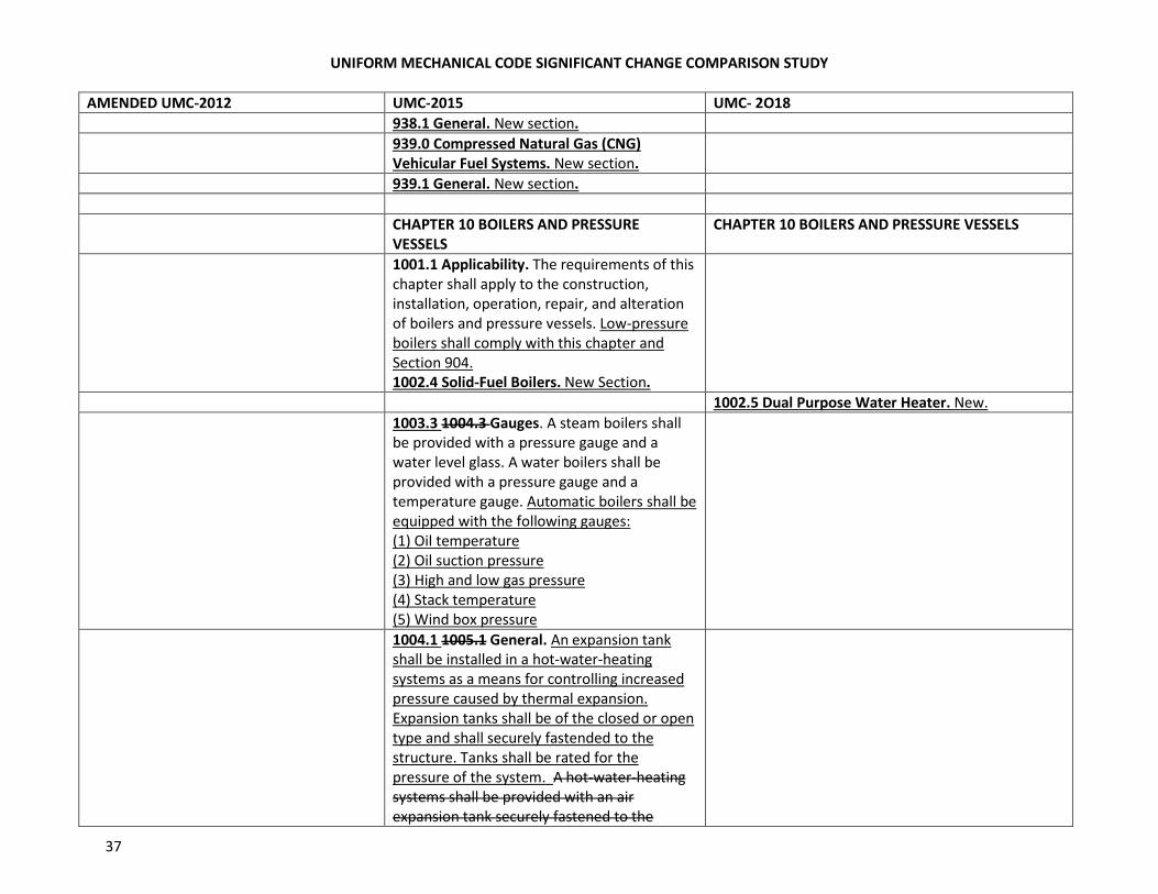
938.1 General. New section.
939.0 Compressed Natural Gas (CNG)
Vehicular Fuel Systems. New section.
939.1 General. New section.
CHAPTER 10 BOILERS AND PRESSURE
VESSELS
CHAPTER 10 BOILERS AND PRESSURE VESSELS
1001.1 Applicability. The requirements of this
chapter shall apply to the construction,
installation, operation, repair, and alteration
of boilers and pressure vessels. Low-pressure
boilers shall comply with this chapter and
Section 904.
1002.4 Solid-Fuel Boilers. New Section.
1002.5 Dual Purpose Water Heater. New.
1003.3 1004.3 Gauges. A steam boilers shall
be provided with a pressure gauge and a
water level glass. A water boilers shall be
provided with a pressure gauge and a
temperature gauge. Automatic boilers shall be
equipped with the following gauges:
(1) Oil temperature
(2) Oil suction pressure
(3) High and low gas pressure
(4) Stack temperature
(5) Wind box pressure
1004.1 1005.1 General. An expansion tank
shall be installed in a hot-water-heating
systems as a means for controlling increased
pressure caused by thermal expansion.
Expansion tanks shall be of the closed or open
type and shall securely fastended to the
structure. Tanks shall be rated for the
pressure of the system. A hot-water-heating
systems shall be provided with an air
expansion tank securely fastened to the
UNIFORM MECHANICAL CODE SIGNIFICANT CHANGE COMPARISON STUDY
38
AMENDED UMC-2012 UMC-2015 UMC- 2O18
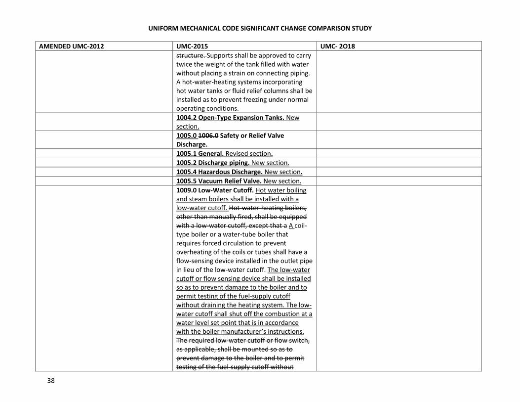
structure. Supports shall be approved to carry
twice the weight of the tank filled with water
without placing a strain on connecting piping.
A hot-water-heating systems incorporating
hot water tanks or fluid relief columns shall be
installed as to prevent freezing under normal
operating conditions.
1004.2 Open-Type Expansion Tanks. New
section.
1005.0 1006.0 Safety or Relief Valve
Discharge.
1005.1 General. Revised section.
1005.2 Discharge piping. New section.
1005.4 Hazardous Discharge. New section.
1005.5 Vacuum Relief Valve. New section.
1009.0 Low-Water Cutoff. Hot water boiling
and steam boilers shall be installed with a
low-water cutoff. Hot-water-heating boilers,
other than manually fired, shall be equipped
with a low-water cutoff, except that a A coil-
type boiler or a water-tube boiler that
requires forced circulation to prevent
overheating of the coils or tubes shall have a
flow-sensing device installed in the outlet pipe
in lieu of the low-water cutoff. The low-water
cutoff or flow sensing device shall be installed
so as to prevent damage to the boiler and to
permit testing of the fuel-supply cutoff
without draining the heating system. The low-
water cutoff shall shut off the combustion at a
water level set point that is in accordance
with the boiler manufacturer’s instructions.
The required low-water cutoff or flow switch,
as applicable, shall be mounted so as to
prevent damage to the boiler and to permit
testing of the fuel-supply cutoff without
UNIFORM MECHANICAL CODE SIGNIFICANT CHANGE COMPARISON STUDY
39
AMENDED UMC-2012 UMC-2015 UMC- 2O18
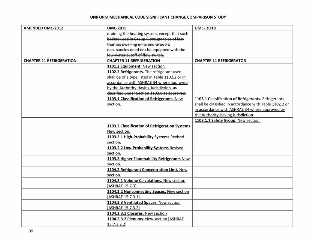
draining the heating system, except that such
boilers used in Group R occupancies of less
than six dwelling units and Group U
occupancies need not be equipped with the
low-water cutoff of flow switch.
CHAPTER 11 REFRIGERATION CHAPTER 11 REFRIGERATION CHAPTER 11 REFRIGERATOR
1101.2 Equipment. New section.
1102.2 Refrigerants. The refrigerant used
shall be of a type listed in Table 1102.2 or in
accordance with ASHRAE 34 where approved
by the Authority Having Jurisdiction. as
classified under Section 1103.0 as approved.
1103.1 Classification of Refrigerants. New
section.
1103.1 Classification of Refrigerants. Refrigerants
shall be classified in accordance with Table 1102.2 or
in accordance with ASHRAE 34 where approved by
the Authority Having Jurisdiction.
1103.1.1 Safety Group. New section.
1103.2 Classification of Refrigeration Systems
New section.
1103.2.1 High-Probability Systems Revised
section.
1103.2.2 Low-Probability Systems Revised
section.
1103.3 Higher Flammability Refrigerants New
section.
1104.2 Refrigerant Concentration Limt. New
section.
1104.2.1 Volume Calculations. New section
[ASHRAE 15:7.3].
1104.2.2 Nonconnecting Spaces. New section
[ASHRAE 15:7.3.1]
1104.2.3 Ventilated Spaces. New section
[ASHRAE 15:7.3.2]
1104.2.3.1 Closures. New section
1104.2.3.2 Plenums. New section [ASHRAE
15:7.3.2.2]
UNIFORM MECHANICAL CODE SIGNIFICANT CHANGE COMPARISON STUDY
40
AMENDED UMC-2012 UMC-2015 UMC- 2O18
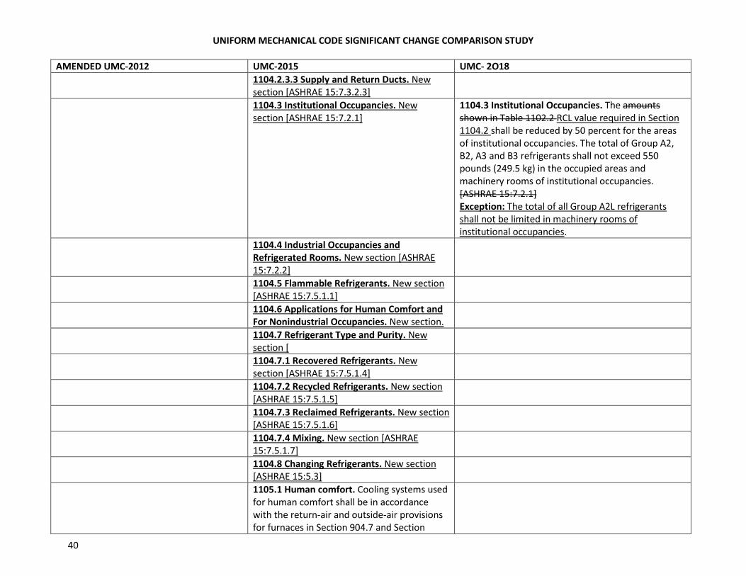
1104.2.3.3 Supply and Return Ducts. New
section [ASHRAE 15:7.3.2.3]
1104.3 Institutional Occupancies. New
section [ASHRAE 15:7.2.1]
1104.3 Institutional Occupancies. The amounts
shown in Table 1102.2 RCL value required in Section
1104.2 shall be reduced by 50 percent for the areas
of institutional occupancies. The total of Group A2,
B2, A3 and B3 refrigerants shall not exceed 550
pounds (249.5 kg) in the occupied areas and
machinery rooms of institutional occupancies.
[ASHRAE 15:7.2.1]
Exception: The total of all Group A2L refrigerants
shall not be limited in machinery rooms of
institutional occupancies.
1104.4 Industrial Occupancies and
Refrigerated Rooms. New section [ASHRAE
15:7.2.2]
1104.5 Flammable Refrigerants. New section
[ASHRAE 15:7.5.1.1]
1104.6 Applications for Human Comfort and
For Nonindustrial Occupancies. New section.
1104.7 Refrigerant Type and Purity. New
section [
1104.7.1 Recovered Refrigerants. New
section [ASHRAE 15:7.5.1.4]
1104.7.2 Recycled Refrigerants. New section
[ASHRAE 15:7.5.1.5]
1104.7.3 Reclaimed Refrigerants. New section
[ASHRAE 15:7.5.1.6]
1104.7.4 Mixing. New section [ASHRAE
15:7.5.1.7]
1104.8 Changing Refrigerants. New section
[ASHRAE 15:5.3]
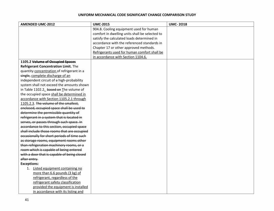
1105.1 Human comfort. Cooling systems used
for human comfort shall be in accordance
with the return-air and outside-air provisions
for furnaces in Section 904.7 and Section
UNIFORM MECHANICAL CODE SIGNIFICANT CHANGE COMPARISON STUDY
41
AMENDED UMC-2012 UMC-2015 UMC- 2O18
904.8. Cooling equipment used for human
comfort in dwelling units shall be selected to
satisfy the calculated loads determined in
accordance with the referenced standards in
Chapter 17 or other approved methods.
Refrigerants used for human comfort shall be
in accordance with Section 1104.6.
1105.2 Volume of Occupied Spaces
Refrigerant Concentration Limit. The
quantity concentration of refrigerant in a
single, complete discharge of an
independent circuit of a high-probability
system shall not exceed the amounts shown
in Table 1102.2. based on The volume of
the occupied space shall be determined in
accordance with Section 1105.2.1 through
1105.2.3. The volume of the smallest,
enclosed, occupied space shall be used to
determine the permissible quantity of
refrigerant in a system that is located in
serves, or passes through such space. In
accordance to this section, occupied space
shall include those rooms that are occupied
occasionally for short periods of time such
as storage rooms, equipment rooms other
than refrigeration machinery rooms, or a
room which is capable of being entered
with a door that is capable of being closed
after entry.
Exceptions:
1. Listed equipment containing no
more than 6.6 pounds (3 kg) of
refrigerant, regardless of the
refrigerant safety classification
provided the equipment is installed
in accordance with its listing and
UNIFORM MECHANICAL CODE SIGNIFICANT CHANGE COMPARISON STUDY
42
AMENDED UMC-2012 UMC-2015 UMC- 2O18
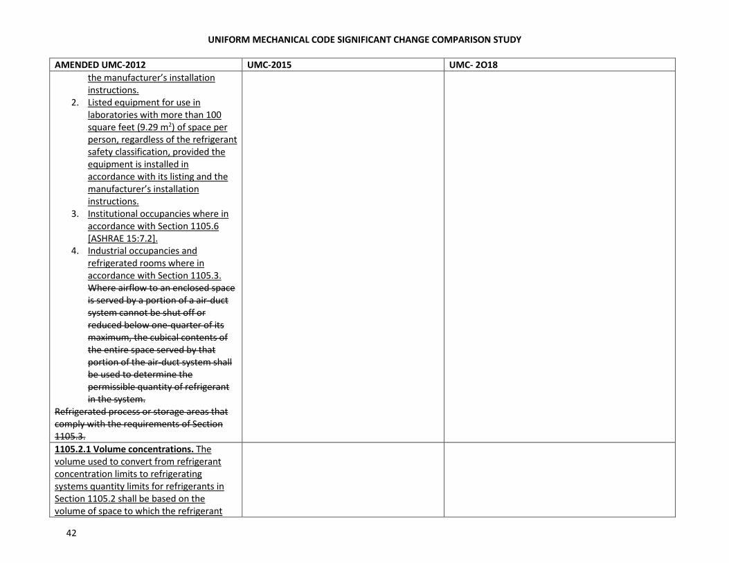
the manufacturer’s installation
instructions.
2. Listed equipment for use in
laboratories with more than 100
square feet (9.29 m2) of space per
person, regardless of the refrigerant
safety classification, provided the
equipment is installed in
accordance with its listing and the
manufacturer’s installation
instructions.
3. Institutional occupancies where in
accordance with Section 1105.6
[ASHRAE 15:7.2].
4. Industrial occupancies and
refrigerated rooms where in
accordance with Section 1105.3.
Where airflow to an enclosed space
is served by a portion of a air-duct
system cannot be shut off or
reduced below one-quarter of its
maximum, the cubical contents of
the entire space served by that
portion of the air-duct system shall
be used to determine the
permissible quantity of refrigerant
in the system.
Refrigerated process or storage areas that
comply with the requirements of Section
1105.3.
1105.2.1 Volume concentrations. The
volume used to convert from refrigerant
concentration limits to refrigerating
systems quantity limits for refrigerants in
Section 1105.2 shall be based on the
volume of space to which the refrigerant
UNIFORM MECHANICAL CODE SIGNIFICANT CHANGE COMPARISON STUDY
43
AMENDED UMC-2012 UMC-2015 UMC- 2O18
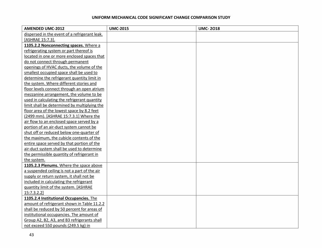
dispersed in the event of a refrigerant leak.
[ASHRAE 15:7.3].
1105.2.2 Nonconnecting spaces. Where a
refrigerating system or part thereof is
located in one or more enclosed spaces that
do not connect through permanent
openings of HVAC ducts, the volume of the
smallest occupied space shall be used to
determine the refrigerant quantity limit in
the system. Where different stories and
floor levels connect through an open atrium
mezzanine arrangement, the volume to be
used in calculating the refrigerant quantity
limit shall be determined by multiplying the
floor area of the lowest space by 8.2 feet
(2499 mm). [ASHRAE 15:7.3.1] Where the
air flow to an enclosed space served by a
portion of an air-duct system cannot be
shut off or reduced below one-quarter of
the maximum, the cubicle contents of the
entire space served by that portion of the
air-duct system shall be used to determine
the permissible quantity of refrigerant in
the system.
1105.2.3 Plenums. Where the space above
a suspended ceiling is not a part of the air
supply or return system, it shall not be
included in calculating the refrigerant
quantity limit of the system. [ASHRAE
15:7.3.2.2]
1105.2.4 Institutional Occupancies. The
amount of refrigerant shown in Table 11.2.2
shall be reduced by 50 percent for areas of
institutional occupancies. The amount of
Group A2, B2, A3, and B3 refrigerants shall
not exceed 550 pounds (249.5 kg) in
UNIFORM MECHANICAL CODE SIGNIFICANT CHANGE COMPARISON STUDY
44
AMENDED UMC-2012 UMC-2015 UMC- 2O18
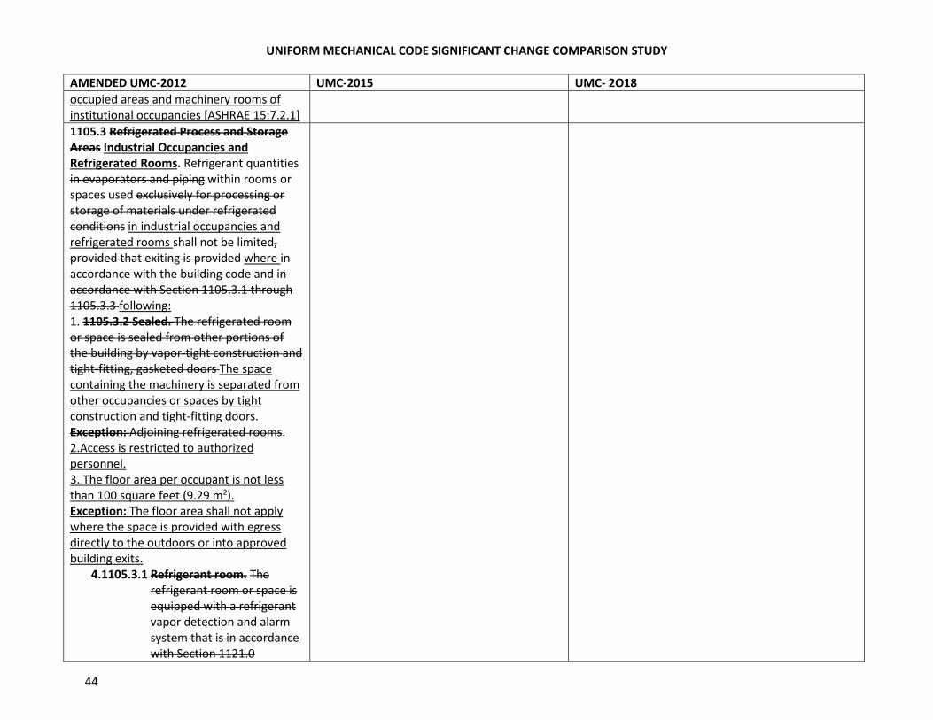
occupied areas and machinery rooms of
institutional occupancies [ASHRAE 15:7.2.1]
1105.3 Refrigerated Process and Storage
Areas Industrial Occupancies and
Refrigerated Rooms. Refrigerant quantities
in evaporators and piping within rooms or
spaces used exclusively for processing or
storage of materials under refrigerated
conditions in industrial occupancies and
refrigerated rooms shall not be limited,
provided that exiting is provided where in
accordance with the building code and in
accordance with Section 1105.3.1 through
1105.3.3 following:
1. 1105.3.2 Sealed. The refrigerated room
or space is sealed from other portions of
the building by vapor-tight construction and
tight-fitting, gasketed doors The space
containing the machinery is separated from
other occupancies or spaces by tight
construction and tight-fitting doors.
Exception: Adjoining refrigerated rooms.
2.Access is restricted to authorized
personnel.
3. The floor area per occupant is not less
than 100 square feet (9.29 m2).
Exception: The floor area shall not apply
where the space is provided with egress
directly to the outdoors or into approved
building exits.
4.1105.3.1 Refrigerant room. The
refrigerant room or space is
equipped with a refrigerant
vapor detection and alarm
system that is in accordance
with Section 1121.0

UNIFORM MECHANICAL CODE SIGNIFICANT CHANGE COMPARISON STUDY
45
AMENDED UMC-2012 UMC-2015 UMC- 2O18
Refrigerant detectors are
installed with the sensing
location and alarm level in
accordance with Section
1107.4.
5. Open flame and surfaces exceeding
8000F (4270C) shall not be
permitted where a Group A2, B2,
A3, or B3 refrigerant, other than
where ammonia is used.
6. 1105.3.3 Lower Flammability Limit.
Where the quantity of a Group A2,
B2, A3, or B3 refrigerant, other than
ammonia, in an independent circuit
will exceed 25 percent of the lower
flammability limit where released to
the surrounding room, the
following shall be provided:
(1) Electrical equipment shall
comply with the requirements
of the electrical code for Class I,
Division 2.
(2) The refrigerant vapor detection
system required by Section
1105.3.1 shall automatically de-
energize electrical power within
the space at vapor
concentrations at or above 25
percent of the lower
flammability limit.
Electrical equipment shall
comply with Class I, Division 2
of NFPA 70 where the quantity
of a Group A2, B2, A3, or B3
refrigerant, other than
ammonia in an independent
UNIFORM MECHANICAL CODE SIGNIFICANT CHANGE COMPARISON STUDY
46
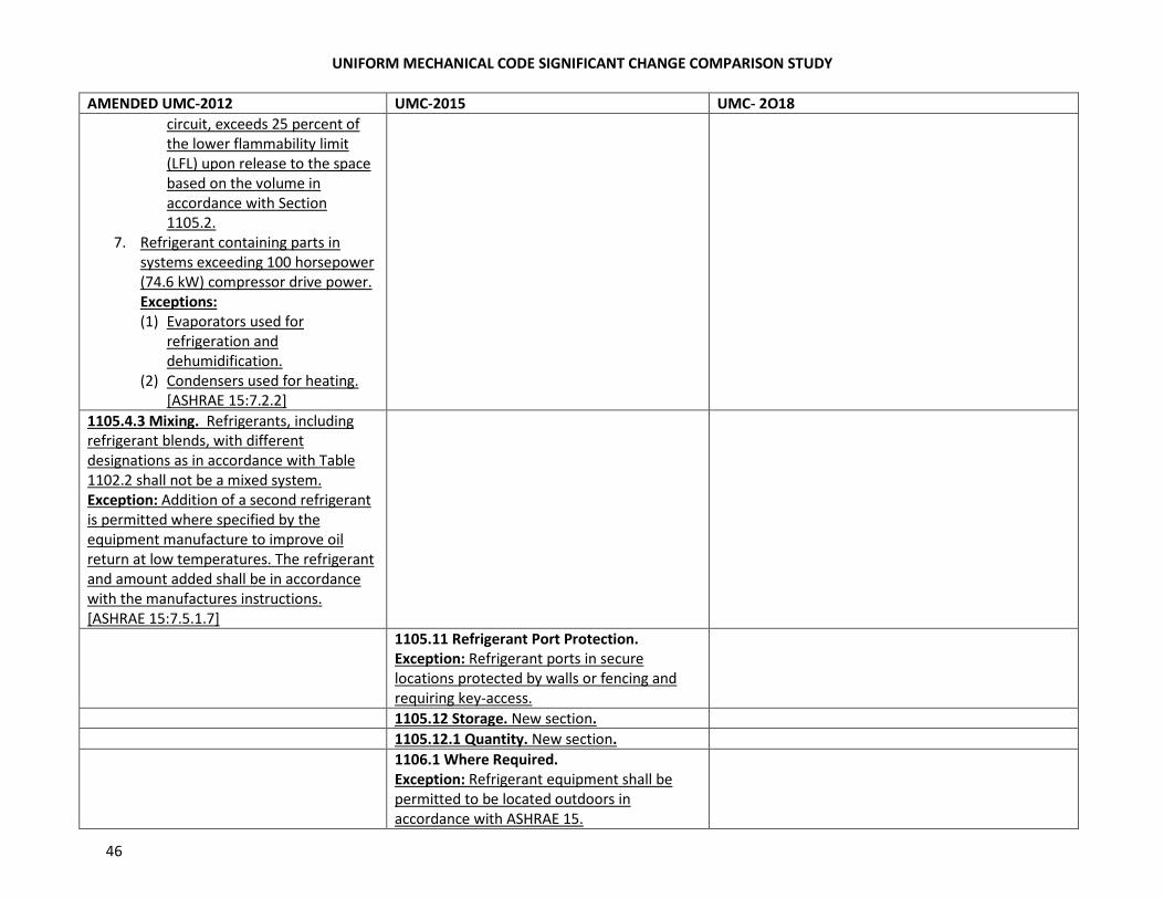
AMENDED UMC-2012 UMC-2015 UMC- 2O18
circuit, exceeds 25 percent of
the lower flammability limit
(LFL) upon release to the space
based on the volume in
accordance with Section
1105.2.
7. Refrigerant containing parts in
systems exceeding 100 horsepower
(74.6 kW) compressor drive power.
Exceptions:
(1) Evaporators used for
refrigeration and
dehumidification.
(2) Condensers used for heating.
[ASHRAE 15:7.2.2]
1105.4.3 Mixing. Refrigerants, including
refrigerant blends, with different
designations as in accordance with Table
1102.2 shall not be a mixed system.
Exception: Addition of a second refrigerant
is permitted where specified by the
equipment manufacture to improve oil
return at low temperatures. The refrigerant
and amount added shall be in accordance
with the manufactures instructions.
[ASHRAE 15:7.5.1.7]
1105.11 Refrigerant Port Protection.
Exception: Refrigerant ports in secure
locations protected by walls or fencing and
requiring key-access.
1105.12 Storage. New section.
1105.12.1 Quantity. New section.
1106.1 Where Required.
Exception: Refrigerant equipment shall be
permitted to be located outdoors in
accordance with ASHRAE 15.
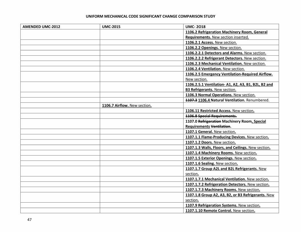
UNIFORM MECHANICAL CODE SIGNIFICANT CHANGE COMPARISON STUDY
47
AMENDED UMC-2012 UMC-2015 UMC- 2O18
1106.2 Refrigeration Machinery Room, General
Requirements. New section inserted.
1106.2.1 Access. New section.
1106.2.2 Openings. New section.
1106.2.2.1 Detectors and Alarms. New section.
1106.2.2.2 Refrigerant Detectors. New section.
1106.2.3 Mechanical Ventilation. New section.
1106.2.4 Ventilation. New section.
1106.2.5 Emergency Ventilation-Required Airflow.
New section.
1106.2.5.1 Ventilation- A1, A2, A3, B1, B2L, B2 and
B3 Refrigerants. New section.
1106.3 Normal Operations. New section.
1107.3 1106.4 Natural Ventilation. Renumbered.
1106.7 Airflow. New section.
1106.11 Restricted Access. New section.
1106.8 Special Requirements.
1107.0 Refrigeration Machinery Room, Special
Requirements Ventilation.
1107.1 General. New section.
1107.1.1 Flame-Producing Devices. New section.
1107.1.2 Doors. New section.
1107.1.3 Walls, Floors, and Ceilings. New section.
1107.1.4 Machinery Rooms. New section.
1107.1.5 Exterior Openings. New section.
1107.1.6 Sealing. New section.
1107.1.7 Group A2L and B2L Refrigerants. New
section.
1107.1.7.1 Mechanical Ventilation. New section.
1107.1.7.2 Refrigeration Detectors. New section.
1107.1.7.3 Machinery Rooms. New section.
1107.1.8 Group A2, A3, B2, or B3 Refrigerants. New
section.
1107.9 Refrigeration Systems. New section.
1107.1.10 Remote Control. New section.
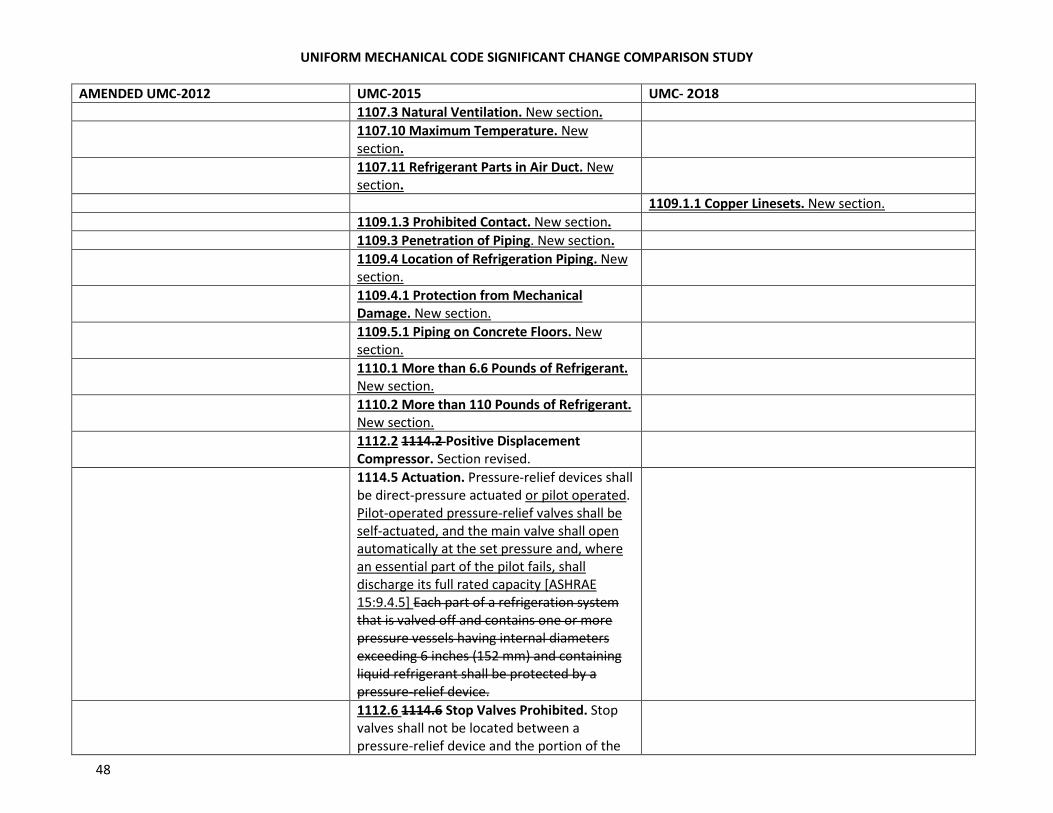
UNIFORM MECHANICAL CODE SIGNIFICANT CHANGE COMPARISON STUDY
48
AMENDED UMC-2012 UMC-2015 UMC- 2O18
1107.3 Natural Ventilation. New section.
1107.10 Maximum Temperature. New
section.
1107.11 Refrigerant Parts in Air Duct. New
section.
1109.1.1 Copper Linesets. New section.
1109.1.3 Prohibited Contact. New section.
1109.3 Penetration of Piping. New section.
1109.4 Location of Refrigeration Piping. New
section.
1109.4.1 Protection from Mechanical
Damage. New section.
1109.5.1 Piping on Concrete Floors. New
section.
1110.1 More than 6.6 Pounds of Refrigerant.
New section.
1110.2 More than 110 Pounds of Refrigerant.
New section.
1112.2 1114.2 Positive Displacement
Compressor. Section revised.
1114.5 Actuation. Pressure-relief devices shall
be direct-pressure actuated or pilot operated.
Pilot-operated pressure-relief valves shall be
self-actuated, and the main valve shall open
automatically at the set pressure and, where
an essential part of the pilot fails, shall
discharge its full rated capacity [ASHRAE
15:9.4.5] Each part of a refrigeration system
that is valved off and contains one or more
pressure vessels having internal diameters
exceeding 6 inches (152 mm) and containing
liquid refrigerant shall be protected by a
pressure-relief device.
1112.6 1114.6 Stop Valves Prohibited. Stop
valves shall not be located between a
pressure-relief device and the portion of the
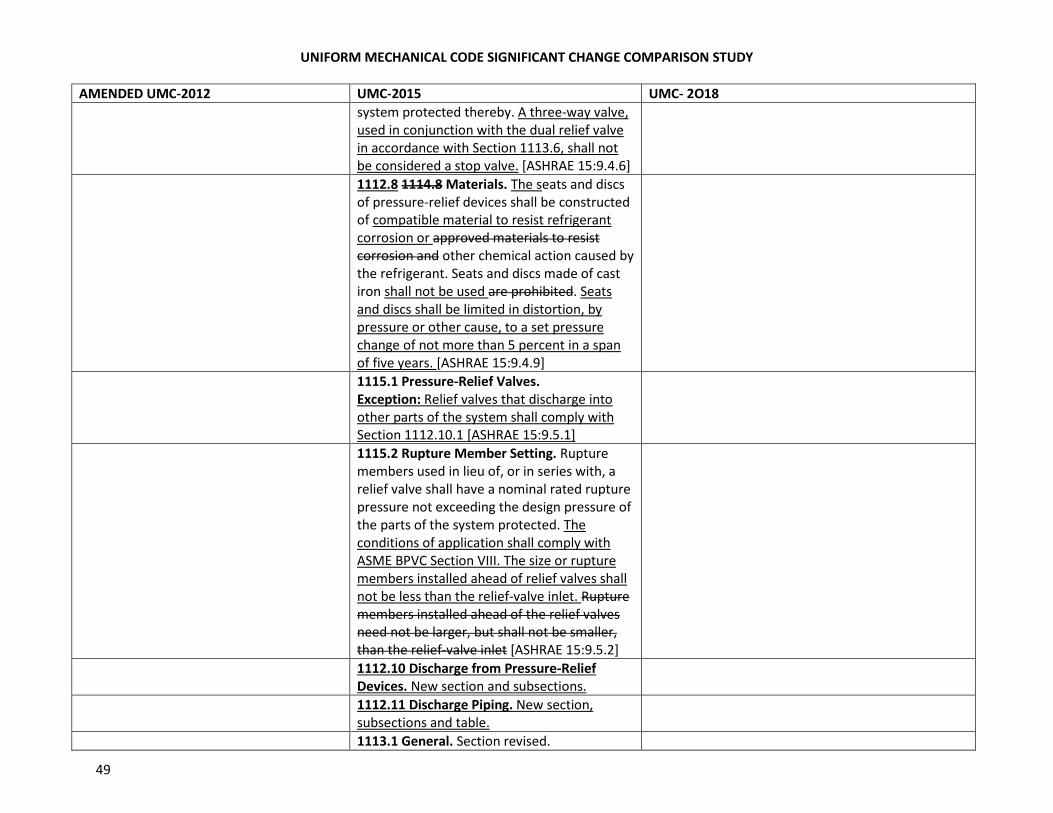
UNIFORM MECHANICAL CODE SIGNIFICANT CHANGE COMPARISON STUDY
49
AMENDED UMC-2012 UMC-2015 UMC- 2O18
system protected thereby. A three-way valve,
used in conjunction with the dual relief valve
in accordance with Section 1113.6, shall not
be considered a stop valve. [ASHRAE 15:9.4.6]
1112.8 1114.8 Materials. The seats and discs
of pressure-relief devices shall be constructed
of compatible material to resist refrigerant
corrosion or approved materials to resist
corrosion and other chemical action caused by
the refrigerant. Seats and discs made of cast
iron shall not be used are prohibited. Seats
and discs shall be limited in distortion, by
pressure or other cause, to a set pressure
change of not more than 5 percent in a span
of five years. [ASHRAE 15:9.4.9]
1115.1 Pressure-Relief Valves.
Exception: Relief valves that discharge into
other parts of the system shall comply with
Section 1112.10.1 [ASHRAE 15:9.5.1]
1115.2 Rupture Member Setting. Rupture
members used in lieu of, or in series with, a
relief valve shall have a nominal rated rupture
pressure not exceeding the design pressure of
the parts of the system protected. The
conditions of application shall comply with
ASME BPVC Section VIII. The size or rupture
members installed ahead of relief valves shall
not be less than the relief-valve inlet. Rupture
members installed ahead of the relief valves
need not be larger, but shall not be smaller,
than the relief-valve inlet [ASHRAE 15:9.5.2]
1112.10 Discharge from Pressure-Relief
Devices. New section and subsections.
1112.11 Discharge Piping. New section,
subsections and table.
1113.1 General. Section revised.
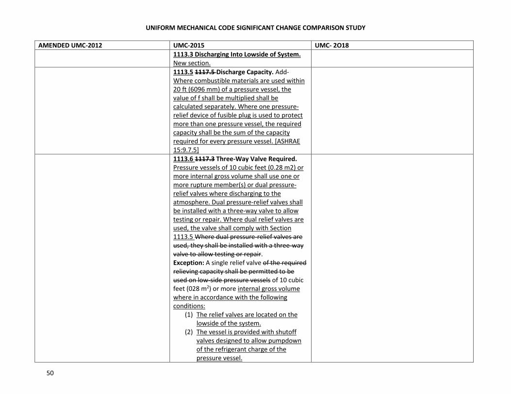
UNIFORM MECHANICAL CODE SIGNIFICANT CHANGE COMPARISON STUDY
50
AMENDED UMC-2012 UMC-2015 UMC- 2O18
1113.3 Discharging Into Lowside of System.
New section.
1113.5 1117.5 Discharge Capacity. Add-
Where combustible materials are used within
20 ft (6096 mm) of a pressure vessel, the
value of f shall be multiplied shall be
calculated separately. Where one pressure-
relief device of fusible plug is used to protect
more than one pressure vessel, the required
capacity shall be the sum of the capacity
required for every pressure vessel. [ASHRAE
15:9.7.5]
1113.6 1117.3 Three-Way Valve Required.
Pressure vessels of 10 cubic feet (0.28 m2) or
more internal gross volume shall use one or
more rupture member(s) or dual pressure-
relief valves where discharging to the
atmosphere. Dual pressure-relief valves shall
be installed with a three-way valve to allow
testing or repair. Where dual relief valves are
used, the valve shall comply with Section
1113.5 Where dual pressure-relief valves are
used, they shall be installed with a three-way
valve to allow testing or repair.
Exception: A single relief valve of the required
relieving capacity shall be permitted to be
used on low-side pressure vessels of 10 cubic
feet (028 m2) or more internal gross volume
where in accordance with the following
conditions:
(1) The relief valves are located on the
lowside of the system.
(2) The vessel is provided with shutoff
valves designed to allow pumpdown
of the refrigerant charge of the
pressure vessel.
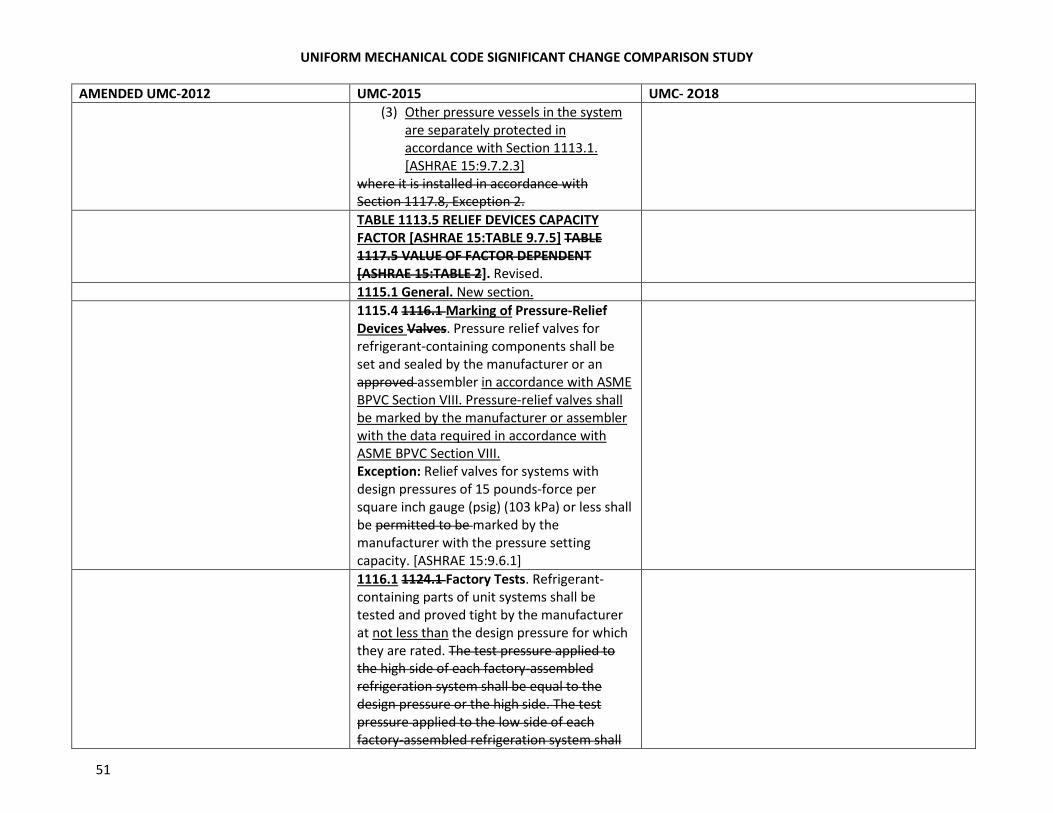
UNIFORM MECHANICAL CODE SIGNIFICANT CHANGE COMPARISON STUDY
51
AMENDED UMC-2012 UMC-2015 UMC- 2O18
(3) Other pressure vessels in the system
are separately protected in
accordance with Section 1113.1.
[ASHRAE 15:9.7.2.3]
where it is installed in accordance with
Section 1117.8, Exception 2.
TABLE 1113.5 RELIEF DEVICES CAPACITY
FACTOR [ASHRAE 15:TABLE 9.7.5] TABLE
1117.5 VALUE OF FACTOR DEPENDENT
[ASHRAE 15:TABLE 2]. Revised.
1115.1 General. New section.
1115.4 1116.1 Marking of Pressure-Relief
Devices Valves. Pressure relief valves for
refrigerant-containing components shall be
set and sealed by the manufacturer or an
approved assembler in accordance with ASME
BPVC Section VIII. Pressure-relief valves shall
be marked by the manufacturer or assembler
with the data required in accordance with
ASME BPVC Section VIII.
Exception: Relief valves for systems with
design pressures of 15 pounds-force per
square inch gauge (psig) (103 kPa) or less shall
be permitted to be marked by the
manufacturer with the pressure setting
capacity. [ASHRAE 15:9.6.1]
1116.1 1124.1 Factory Tests. Refrigerant-
containing parts of unit systems shall be
tested and proved tight by the manufacturer
at not less than the design pressure for which
they are rated. The test pressure applied to
the high side of each factory-assembled
refrigeration system shall be equal to the
design pressure or the high side. The test
pressure applied to the low side of each
factory-assembled refrigeration system shall
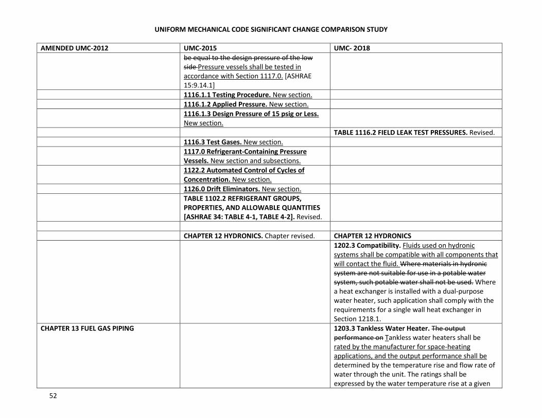
UNIFORM MECHANICAL CODE SIGNIFICANT CHANGE COMPARISON STUDY
52
AMENDED UMC-2012 UMC-2015 UMC- 2O18
be equal to the design pressure of the low
side Pressure vessels shall be tested in
accordance with Section 1117.0. [ASHRAE
15:9.14.1]
1116.1.1 Testing Procedure. New section.
1116.1.2 Applied Pressure. New section.
1116.1.3 Design Pressure of 15 psig or Less.
New section.
TABLE 1116.2 FIELD LEAK TEST PRESSURES. Revised.
1116.3 Test Gases. New section.
1117.0 Refrigerant-Containing Pressure
Vessels. New section and subsections.
1122.2 Automated Control of Cycles of
Concentration. New section.
1126.0 Drift Eliminators. New section.
TABLE 1102.2 REFRIGERANT GROUPS,
PROPERTIES, AND ALLOWABLE QUANTITIES
[ASHRAE 34: TABLE 4-1, TABLE 4-2]. Revised.
CHAPTER 12 HYDRONICS. Chapter revised. CHAPTER 12 HYDRONICS
1202.3 Compatibility. Fluids used on hydronic
systems shall be compatible with all components that
will contact the fluid. Where materials in hydronic
system are not suitable for use in a potable water
system, such potable water shall not be used. Where
a heat exchanger is installed with a dual-purpose
water heater, such application shall comply with the
requirements for a single wall heat exchanger in
Section 1218.1.
CHAPTER 13 FUEL GAS PIPING 1203.3 Tankless Water Heater. The output
performance on Tankless water heaters shall be
rated by the manufacturer for space-heating
applications, and the output performance shall be
determined by the temperature rise and flow rate of
water through the unit. The ratings shall be
expressed by the water temperature rise at a given
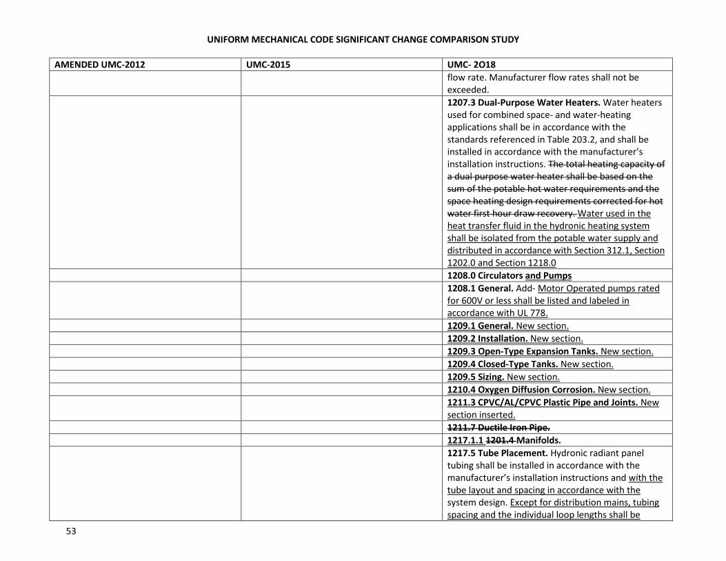
UNIFORM MECHANICAL CODE SIGNIFICANT CHANGE COMPARISON STUDY
53
AMENDED UMC-2012 UMC-2015 UMC- 2O18
flow rate. Manufacturer flow rates shall not be
exceeded.
1207.3 Dual-Purpose Water Heaters. Water heaters
used for combined space- and water-heating
applications shall be in accordance with the
standards referenced in Table 203.2, and shall be
installed in accordance with the manufacturer’s
installation instructions. The total heating capacity of
a dual purpose water heater shall be based on the
sum of the potable hot water requirements and the
space heating design requirements corrected for hot
water first hour draw recovery. Water used in the
heat transfer fluid in the hydronic heating system
shall be isolated from the potable water supply and
distributed in accordance with Section 312.1, Section
1202.0 and Section 1218.0
1208.0 Circulators and Pumps
1208.1 General. Add- Motor Operated pumps rated
for 600V or less shall be listed and labeled in
accordance with UL 778.
1209.1 General. New section.
1209.2 Installation. New section.
1209.3 Open-Type Expansion Tanks. New section.
1209.4 Closed-Type Tanks. New section.
1209.5 Sizing. New section.
1210.4 Oxygen Diffusion Corrosion. New section.
1211.3 CPVC/AL/CPVC Plastic Pipe and Joints. New
section inserted.
1211.7 Ductile Iron Pipe.
1217.1.1 1201.4 Manifolds.
1217.5 Tube Placement. Hydronic radiant panel
tubing shall be installed in accordance with the
manufacturer’s installation instructions and with the
tube layout and spacing in accordance with the
system design. Except for distribution mains, tubing
spacing and the individual loop lengths shall be
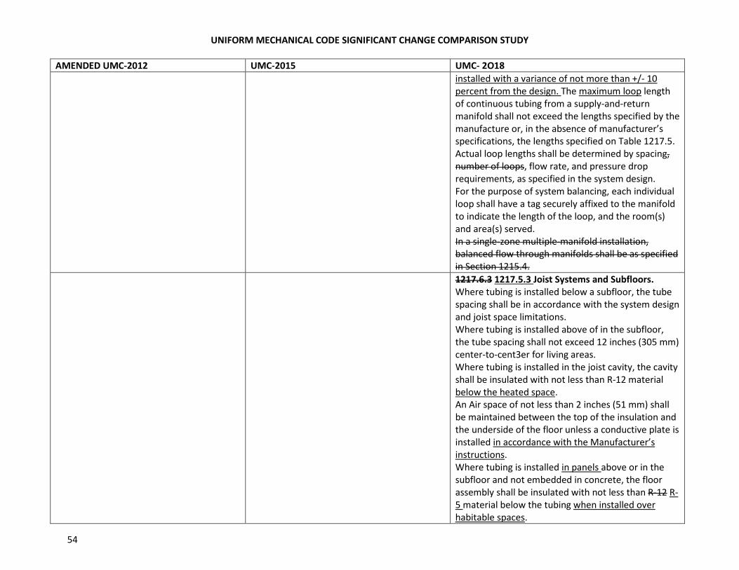
UNIFORM MECHANICAL CODE SIGNIFICANT CHANGE COMPARISON STUDY
54
AMENDED UMC-2012 UMC-2015 UMC- 2O18
installed with a variance of not more than +/- 10
percent from the design. The maximum loop length
of continuous tubing from a supply-and-return
manifold shall not exceed the lengths specified by the
manufacture or, in the absence of manufacturer’s
specifications, the lengths specified on Table 1217.5.
Actual loop lengths shall be determined by spacing,
number of loops, flow rate, and pressure drop
requirements, as specified in the system design.
For the purpose of system balancing, each individual
loop shall have a tag securely affixed to the manifold
to indicate the length of the loop, and the room(s)
and area(s) served.
In a single-zone multiple-manifold installation,
balanced flow through manifolds shall be as specified
in Section 1215.4.
1217.6.3 1217.5.3 Joist Systems and Subfloors.
Where tubing is installed below a subfloor, the tube
spacing shall be in accordance with the system design
and joist space limitations.
Where tubing is installed above of in the subfloor,
the tube spacing shall not exceed 12 inches (305 mm)
center-to-cent3er for living areas.
Where tubing is installed in the joist cavity, the cavity
shall be insulated with not less than R-12 material
below the heated space.
An Air space of not less than 2 inches (51 mm) shall
be maintained between the top of the insulation and
the underside of the floor unless a conductive plate is
installed in accordance with the Manufacturer’s
instructions.
Where tubing is installed in panels above or in the
subfloor and not embedded in concrete, the floor
assembly shall be insulated with not less than R-12 R-
5 material below the tubing when installed over
habitable spaces.
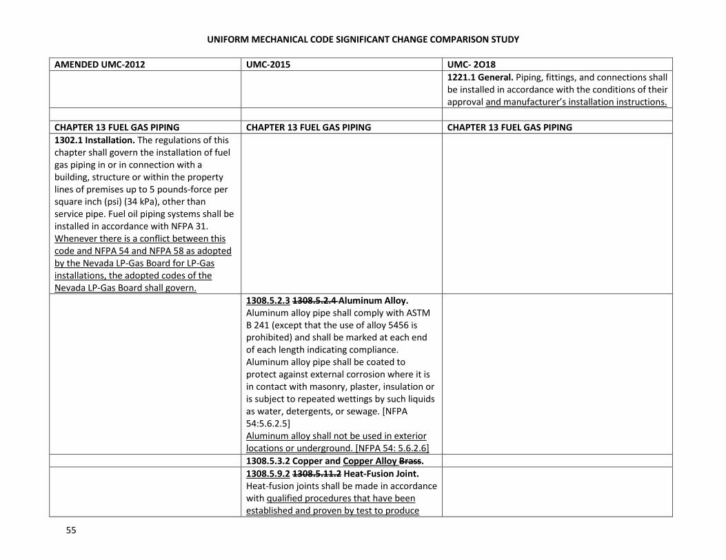
UNIFORM MECHANICAL CODE SIGNIFICANT CHANGE COMPARISON STUDY
55
AMENDED UMC-2012 UMC-2015 UMC- 2O18
1221.1 General. Piping, fittings, and connections shall
be installed in accordance with the conditions of their
approval and manufacturer’s installation instructions.
CHAPTER 13 FUEL GAS PIPING CHAPTER 13 FUEL GAS PIPING CHAPTER 13 FUEL GAS PIPING
1302.1 Installation. The regulations of this
chapter shall govern the installation of fuel
gas piping in or in connection with a
building, structure or within the property
lines of premises up to 5 pounds-force per
square inch (psi) (34 kPa), other than
service pipe. Fuel oil piping systems shall be
installed in accordance with NFPA 31.
Whenever there is a conflict between this
code and NFPA 54 and NFPA 58 as adopted
by the Nevada LP-Gas Board for LP-Gas
installations, the adopted codes of the
Nevada LP-Gas Board shall govern.
1308.5.2.3 1308.5.2.4 Aluminum Alloy.
Aluminum alloy pipe shall comply with ASTM
B 241 (except that the use of alloy 5456 is
prohibited) and shall be marked at each end
of each length indicating compliance.
Aluminum alloy pipe shall be coated to
protect against external corrosion where it is
in contact with masonry, plaster, insulation or
is subject to repeated wettings by such liquids
as water, detergents, or sewage. [NFPA
54:5.6.2.5]
Aluminum alloy shall not be used in exterior
locations or underground. [NFPA 54: 5.6.2.6]
1308.5.3.2 Copper and Copper Alloy Brass.
1308.5.9.2 1308.5.11.2 Heat-Fusion Joint.
Heat-fusion joints shall be made in accordance
with qualified procedures that have been
established and proven by test to produce
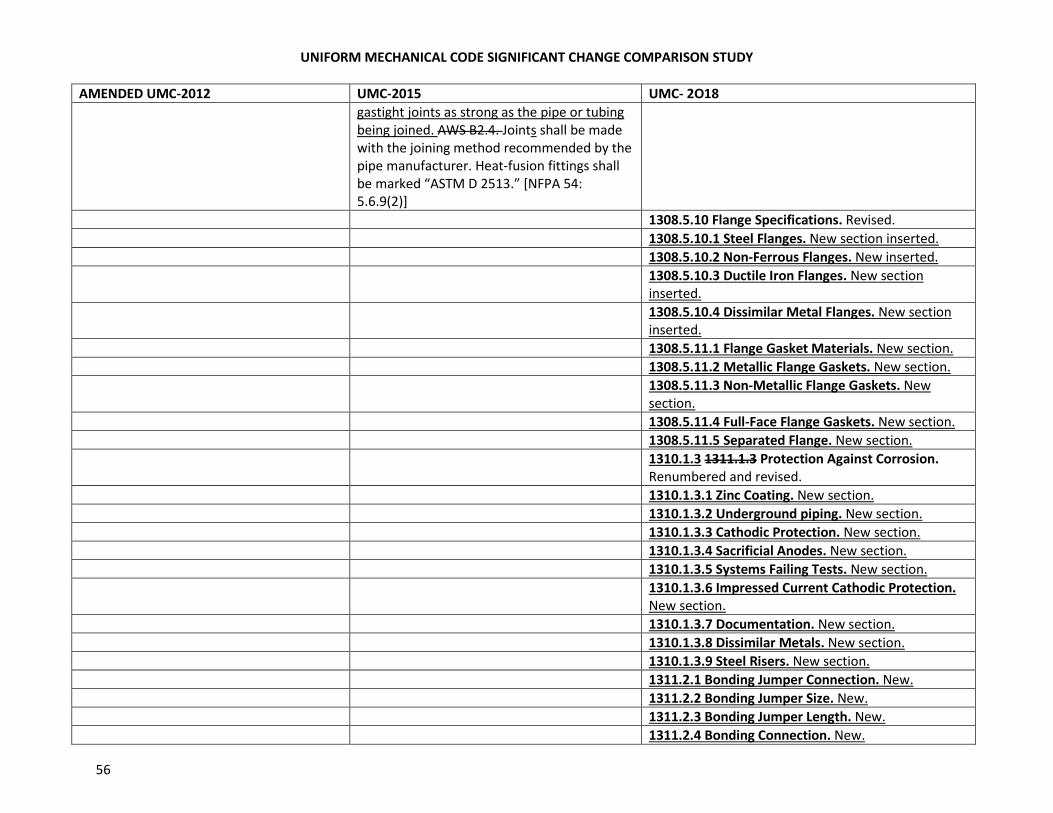
UNIFORM MECHANICAL CODE SIGNIFICANT CHANGE COMPARISON STUDY
56
AMENDED UMC-2012 UMC-2015 UMC- 2O18
gastight joints as strong as the pipe or tubing
being joined. AWS B2.4. Joints shall be made
with the joining method recommended by the
pipe manufacturer. Heat-fusion fittings shall
be marked “ASTM D 2513.” [NFPA 54:
5.6.9(2)]
1308.5.10 Flange Specifications. Revised.
1308.5.10.1 Steel Flanges. New section inserted.
1308.5.10.2 Non-Ferrous Flanges. New inserted.
1308.5.10.3 Ductile Iron Flanges. New section
inserted.
1308.5.10.4 Dissimilar Metal Flanges. New section
inserted.
1308.5.11.1 Flange Gasket Materials. New section.
1308.5.11.2 Metallic Flange Gaskets. New section.
1308.5.11.3 Non-Metallic Flange Gaskets. New
section.
1308.5.11.4 Full-Face Flange Gaskets. New section.
1308.5.11.5 Separated Flange. New section.
1310.1.3 1311.1.3 Protection Against Corrosion.
Renumbered and revised.
1310.1.3.1 Zinc Coating. New section.
1310.1.3.2 Underground piping. New section.
1310.1.3.3 Cathodic Protection. New section.
1310.1.3.4 Sacrificial Anodes. New section.
1310.1.3.5 Systems Failing Tests. New section.
1310.1.3.6 Impressed Current Cathodic Protection.
New section.
1310.1.3.7 Documentation. New section.
1310.1.3.8 Dissimilar Metals. New section.
1310.1.3.9 Steel Risers. New section.
1311.2.1 Bonding Jumper Connection. New.
1311.2.2 Bonding Jumper Size. New.
1311.2.3 Bonding Jumper Length. New.
1311.2.4 Bonding Connection. New.
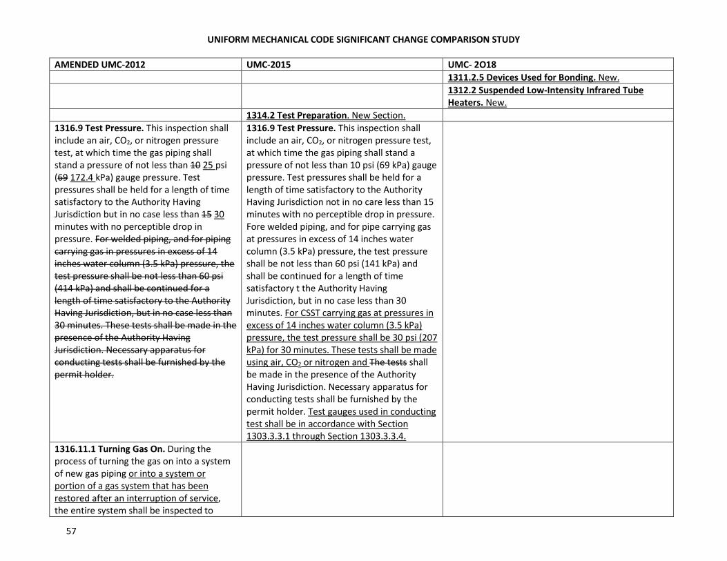
UNIFORM MECHANICAL CODE SIGNIFICANT CHANGE COMPARISON STUDY
57
AMENDED UMC-2012 UMC-2015 UMC- 2O18
1311.2.5 Devices Used for Bonding. New.
1312.2 Suspended Low-Intensity Infrared Tube
Heaters. New.
1314.2 Test Preparation. New Section.
1316.9 Test Pressure. This inspection shall
include an air, CO2, or nitrogen pressure
test, at which time the gas piping shall
stand a pressure of not less than 10 25 psi
(69 172.4 kPa) gauge pressure. Test
pressures shall be held for a length of time
satisfactory to the Authority Having
Jurisdiction but in no case less than 15 30
minutes with no perceptible drop in
pressure. For welded piping, and for piping
carrying gas in pressures in excess of 14
inches water column (3.5 kPa) pressure, the
test pressure shall be not less than 60 psi
(414 kPa) and shall be continued for a
length of time satisfactory to the Authority
Having Jurisdiction, but in no case less than
30 minutes. These tests shall be made in the
presence of the Authority Having
Jurisdiction. Necessary apparatus for
conducting tests shall be furnished by the
permit holder.
1316.9 Test Pressure. This inspection shall
include an air, CO2, or nitrogen pressure test,
at which time the gas piping shall stand a
pressure of not less than 10 psi (69 kPa) gauge
pressure. Test pressures shall be held for a
length of time satisfactory to the Authority
Having Jurisdiction not in no care less than 15
minutes with no perceptible drop in pressure.
Fore welded piping, and for pipe carrying gas
at pressures in excess of 14 inches water
column (3.5 kPa) pressure, the test pressure
shall be not less than 60 psi (141 kPa) and
shall be continued for a length of time
satisfactory t the Authority Having
Jurisdiction, but in no case less than 30
minutes. For CSST carrying gas at pressures in
excess of 14 inches water column (3.5 kPa)
pressure, the test pressure shall be 30 psi (207
kPa) for 30 minutes. These tests shall be made
using air, CO2 or nitrogen and The tests shall
be made in the presence of the Authority
Having Jurisdiction. Necessary apparatus for
conducting tests shall be furnished by the
permit holder. Test gauges used in conducting
test shall be in accordance with Section
1303.3.3.1 through Section 1303.3.3.4.
1316.11.1 Turning Gas On. During the
process of turning the gas on into a system
of new gas piping or into a system or
portion of a gas system that has been
restored after an interruption of service,
the entire system shall be inspected to
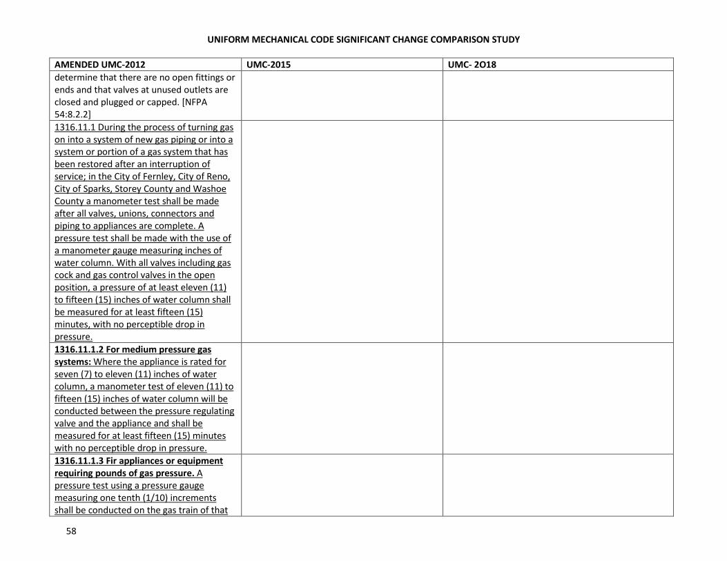
UNIFORM MECHANICAL CODE SIGNIFICANT CHANGE COMPARISON STUDY
58
AMENDED UMC-2012 UMC-2015 UMC- 2O18
determine that there are no open fittings or
ends and that valves at unused outlets are
closed and plugged or capped. [NFPA
54:8.2.2]
1316.11.1 During the process of turning gas
on into a system of new gas piping or into a
system or portion of a gas system that has
been restored after an interruption of
service; in the City of Fernley, City of Reno,
City of Sparks, Storey County and Washoe
County a manometer test shall be made
after all valves, unions, connectors and
piping to appliances are complete. A
pressure test shall be made with the use of
a manometer gauge measuring inches of
water column. With all valves including gas
cock and gas control valves in the open
position, a pressure of at least eleven (11)
to fifteen (15) inches of water column shall
be measured for at least fifteen (15)
minutes, with no perceptible drop in
pressure.
1316.11.1.2 For medium pressure gas
systems: Where the appliance is rated for
seven (7) to eleven (11) inches of water
column, a manometer test of eleven (11) to
fifteen (15) inches of water column will be
conducted between the pressure regulating
valve and the appliance and shall be
measured for at least fifteen (15) minutes
with no perceptible drop in pressure.
1316.11.1.3 Fir appliances or equipment
requiring pounds of gas pressure. A
pressure test using a pressure gauge
measuring one tenth (1/10) increments
shall be conducted on the gas train of that
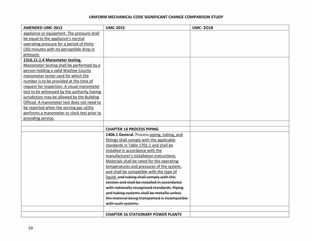
UNIFORM MECHANICAL CODE SIGNIFICANT CHANGE COMPARISON STUDY
59
AMENDED UMC-2012 UMC-2015 UMC- 2O18
appliance or equipment. The pressure shall
be equal to the appliance’s normal
operating pressure for a period of thirty
(30) minutes with no perceptible drop in
pressure.
1316.11.1.4 Manometer testing.
Manometer testing shall be performed by a
person holding a valid Washoe County
manometer tester card for which the
number is to be provided at the time of
request for inspection. A visual manometer
test to be witnessed by the authority having
jurisdiction may be allowed by the Building
Official. A manometer test does not need to
be reported when the serving gas utility
performs a manometer or clock test prior to
providing service.
CHAPTER 14 PROCESS PIPING
1406.1 General. Process piping, tubing, and
fittings shall comply with the applicable
standards in Table 1701.1 and shall be
installed in accordance with the
manufacturer’s installation instructions.
Materials shall be rated for the operating
temperatures and pressures of the system,
and shall be compatible with the type of
liquid. and tubing shall comply with this
section and shall be installed in accordance
with nationally recognized standards. Piping
and tubing systems shall be metallic unless
the material being transported is incompatible
with such systems.
CHAPTER 16 STATIONARY POWER PLANTS
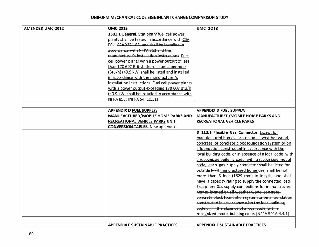
UNIFORM MECHANICAL CODE SIGNIFICANT CHANGE COMPARISON STUDY
60
AMENDED UMC-2012 UMC-2015 UMC- 2O18
1601.1 General. Stationary fuel cell power
plants shall be tested in accordance with CSA
FC-1 CZA XZ21.83, and shall be installed in
accordance with NFPA 853 and the
manufacturer’s installation instructions. Fuel
cell power plants with a power output of less
than 170 607 British thermal units per hour
(Btu/h) (49.9 kW) shall be listed and installed
in accordance with the manufacturer’s
installation instructions. Fuel cell power plants
with a power output exceeding 170 607 Btu/h
(49.9 kW) shall be installed in accordance with
NFPA 853. [NFPA 54: 10.31]
APPENDIX D FUEL SUPPLY:
MANUFACTURED/MOBILE HOME PARKS AND
RECREATIONAL VEHICLE PARKS UNIT
CONVERSION TABLES. New appendix.
APPENDIX D FUEL SUPPLY:
MANUFACTURED/MOBILE HOME PARKS AND
RECREATIONAL VEHICLE PARKS
D 113.1 Flexible Gas Connector. Except for
manufactured homes located on all-weather wood,
concrete, or concrete block foundation system or on
a foundation constructed in accordance with the
local building code, or in absence of a local code, with
a recognized building code, with a recognized model
code, each gas supply connector shall be listed for
outside M/H manufactured home use, shall be not
more than 6 feet (1829 mm) in length, and shall
have a capacity rating to supply the connected load.
Exception: Gas supply connections for manufactured
homes located on all-weather wood, concrete,
concrete block foundation system or on a foundation
constructed in accordance with the local building
code or, in the absence of a local code, with a
recognized model building code. [NFPA 501A:4.4.1]
APPENDIX E SUSTAINABLE PRACTICES APPENDIX E SUSTAINABLE PRACTICES
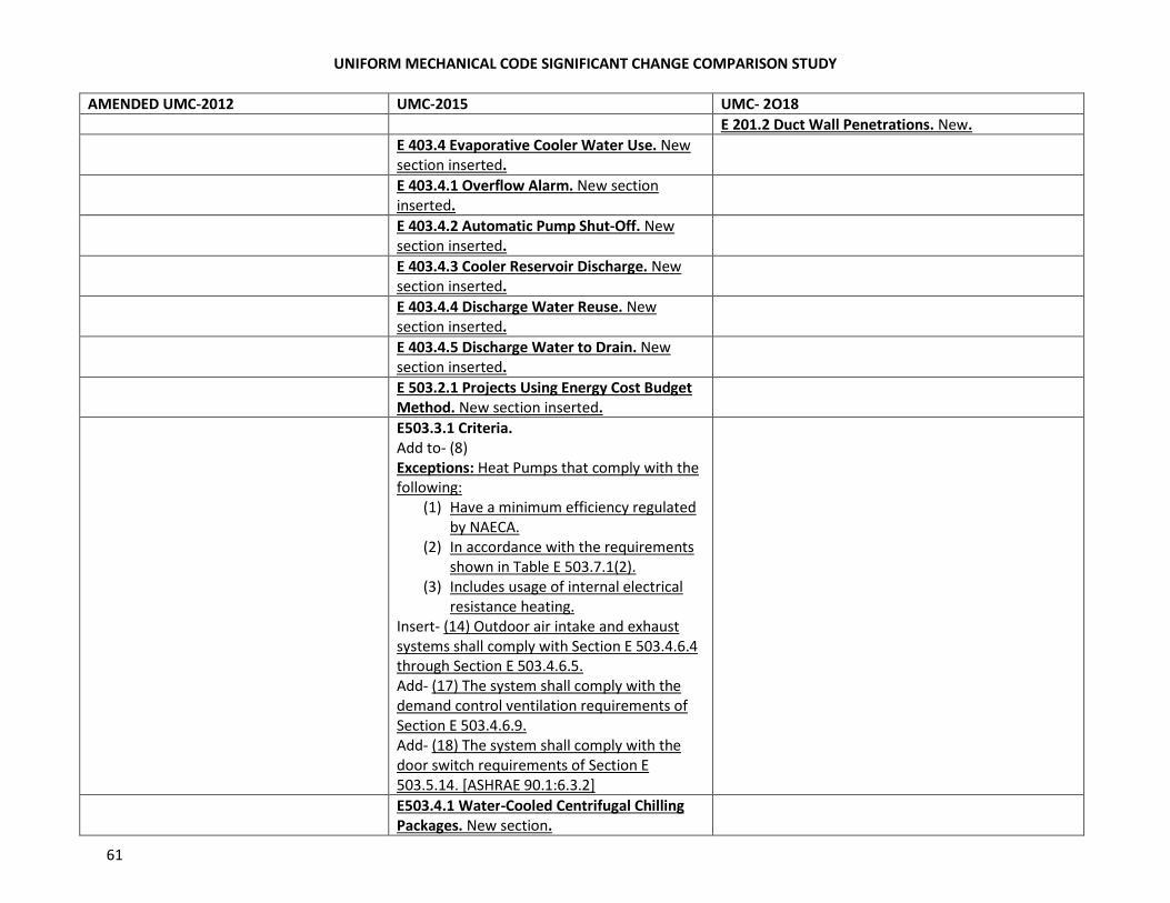
UNIFORM MECHANICAL CODE SIGNIFICANT CHANGE COMPARISON STUDY
61
AMENDED UMC-2012 UMC-2015 UMC- 2O18
E 201.2 Duct Wall Penetrations. New.
E 403.4 Evaporative Cooler Water Use. New
section inserted.
E 403.4.1 Overflow Alarm. New section
inserted.
E 403.4.2 Automatic Pump Shut-Off. New
section inserted.
E 403.4.3 Cooler Reservoir Discharge. New
section inserted.
E 403.4.4 Discharge Water Reuse. New
section inserted.
E 403.4.5 Discharge Water to Drain. New
section inserted.
E 503.2.1 Projects Using Energy Cost Budget
Method. New section inserted.
E503.3.1 Criteria.
Add to- (8)
Exceptions: Heat Pumps that comply with the
following:
(1) Have a minimum efficiency regulated
by NAECA.
(2) In accordance with the requirements
shown in Table E 503.7.1(2).
(3) Includes usage of internal electrical
resistance heating.
Insert- (14) Outdoor air intake and exhaust
systems shall comply with Section E 503.4.6.4
through Section E 503.4.6.5.
Add- (17) The system shall comply with the
demand control ventilation requirements of
Section E 503.4.6.9.
Add- (18) The system shall comply with the
door switch requirements of Section E
503.5.14. [ASHRAE 90.1:6.3.2]
E503.4.1 Water-Cooled Centrifugal Chilling
Packages. New section.
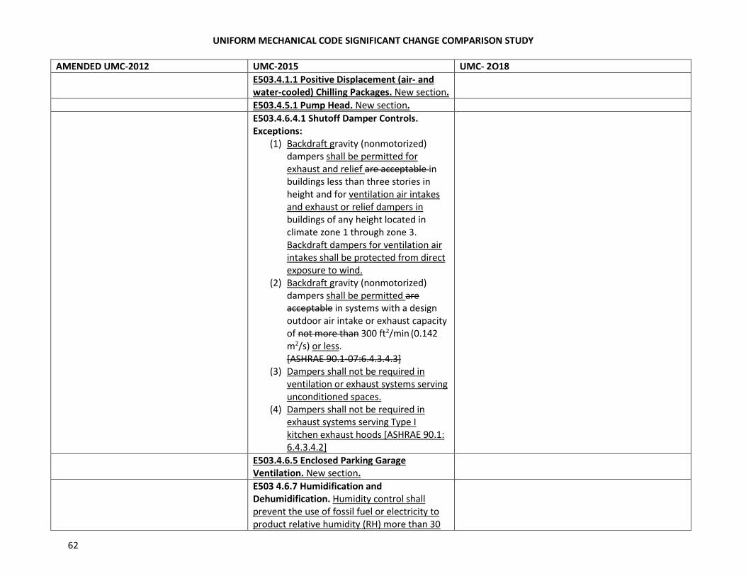
UNIFORM MECHANICAL CODE SIGNIFICANT CHANGE COMPARISON STUDY
62
AMENDED UMC-2012 UMC-2015 UMC- 2O18
E503.4.1.1 Positive Displacement (air- and
water-cooled) Chilling Packages. New section.
E503.4.5.1 Pump Head. New section.
E503.4.6.4.1 Shutoff Damper Controls.
Exceptions:
(1) Backdraft gravity (nonmotorized)
dampers shall be permitted for
exhaust and relief are acceptable in
buildings less than three stories in
height and for ventilation air intakes
and exhaust or relief dampers in
buildings of any height located in
climate zone 1 through zone 3.
Backdraft dampers for ventilation air
intakes shall be protected from direct
exposure to wind.
(2) Backdraft gravity (nonmotorized)
dampers shall be permitted are
acceptable in systems with a design
outdoor air intake or exhaust capacity
of not more than 300 ft2/min (0.142
m2/s) or less.
[ASHRAE 90.1-07:6.4.3.4.3]
(3) Dampers shall not be required in
ventilation or exhaust systems serving
unconditioned spaces.
(4) Dampers shall not be required in
exhaust systems serving Type I
kitchen exhaust hoods [ASHRAE 90.1:
6.4.3.4.2]
E503.4.6.5 Enclosed Parking Garage
Ventilation. New section.
E503 4.6.7 Humidification and
Dehumidification. Humidity control shall
prevent the use of fossil fuel or electricity to
product relative humidity (RH) more than 30
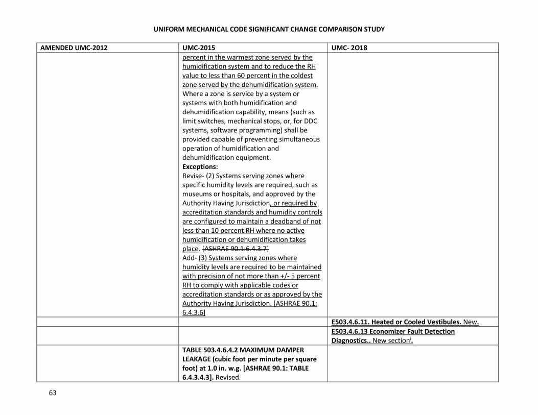
UNIFORM MECHANICAL CODE SIGNIFICANT CHANGE COMPARISON STUDY
63
AMENDED UMC-2012 UMC-2015 UMC- 2O18
percent in the warmest zone served by the
humidification system and to reduce the RH
value to less than 60 percent in the coldest
zone served by the dehumidification system.
Where a zone is service by a system or
systems with both humidification and
dehumidification capability, means (such as
limit switches, mechanical stops, or, for DDC
systems, software programming) shall be
provided capable of preventing simultaneous
operation of humidification and
dehumidification equipment.
Exceptions:
Revise- (2) Systems serving zones where
specific humidity levels are required, such as
museums or hospitals, and approved by the
Authority Having Jurisdiction, or required by
accreditation standards and humidity controls
are configured to maintain a deadband of not
less than 10 percent RH where no active
humidification or dehumidification takes
place. [ASHRAE 90.1:6.4.3.7]
Add- (3) Systems serving zones where
humidity levels are required to be maintained
with precision of not more than +/- 5 percent
RH to comply with applicable codes or
accreditation standards or as approved by the
Authority Having Jurisdiction. [ASHRAE 90.1:
6.4.3.6]
E503.4.6.11. Heated or Cooled Vestibules. New.
E503.4.6.13 Economizer Fault Detection
Diagnostics.. New sectioni.
TABLE 503.4.6.4.2 MAXIMUM DAMPER
LEAKAGE (cubic foot per minute per square
foot) at 1.0 in. w.g. [ASHRAE 90.1: TABLE
6.4.3.4.3]. Revised.
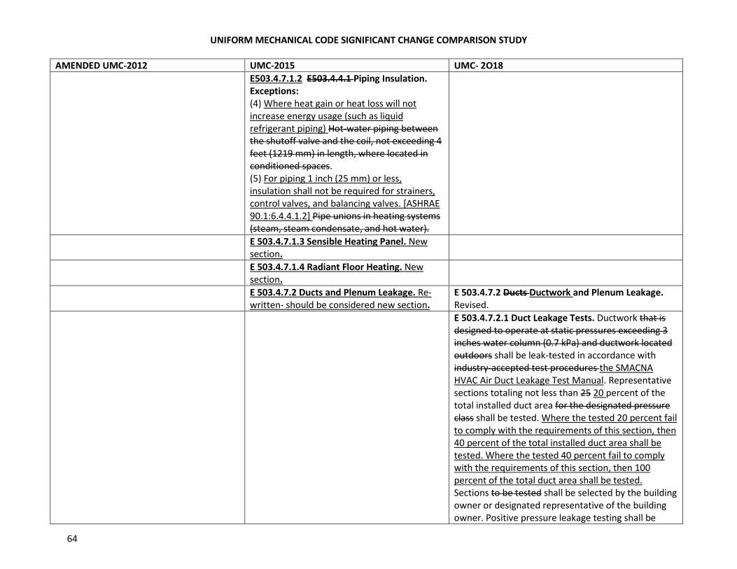
UNIFORM MECHANICAL CODE SIGNIFICANT CHANGE COMPARISON STUDY
64
AMENDED UMC-2012 UMC-2015 UMC- 2O18
E503.4.7.1.2 E503.4.4.1 Piping Insulation.
Exceptions:
(4) Where heat gain or heat loss will not
increase energy usage (such as liquid
refrigerant piping) Hot-water piping between
the shutoff valve and the coil, not exceeding 4
feet (1219 mm) in length, where located in
conditioned spaces.
(5) For piping 1 inch (25 mm) or less,
insulation shall not be required for strainers,
control valves, and balancing valves. [ASHRAE
90.1:6.4.4.1.2] Pipe unions in heating systems
(steam, steam condensate, and hot water).
E 503.4.7.1.3 Sensible Heating Panel. New
section.
E 503.4.7.1.4 Radiant Floor Heating. New
section.
E 503.4.7.2 Ducts and Plenum Leakage. Re-
written- should be considered new section.
E 503.4.7.2 Ducts Ductwork and Plenum Leakage.
Revised.
E 503.4.7.2.1 Duct Leakage Tests. Ductwork that is
designed to operate at static pressures exceeding 3
inches water column (0.7 kPa) and ductwork located
outdoors shall be leak-tested in accordance with
industry-accepted test procedures the SMACNA
HVAC Air Duct Leakage Test Manual. Representative
sections totaling not less than 25 20 percent of the
total installed duct area for the designated pressure
class shall be tested. Where the tested 20 percent fail
to comply with the requirements of this section, then
40 percent of the total installed duct area shall be
tested. Where the tested 40 percent fail to comply
with the requirements of this section, then 100
percent of the total duct area shall be tested.
Sections to be tested shall be selected by the building
owner or designated representative of the building
owner. Positive pressure leakage testing shall be
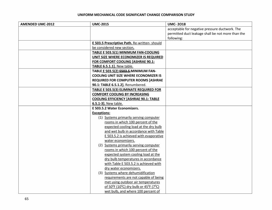
UNIFORM MECHANICAL CODE SIGNIFICANT CHANGE COMPARISON STUDY
65
AMENDED UMC-2012 UMC-2015 UMC- 2O18
acceptable for negative pressure ductwork. The
permitted duct leakage shall be not more than the
following:
E 503.5 Prescriptive Path. Re-written- should
be considered new section.
TABLE E 503.5(1) MINIMUM FAN-COOLING
UNIT SIZE WHERE ECONOMIZER IS REQUIRED
FOR COMFORT COOLING [ASHRAE 90.1:
TABLE 6.5.1.1]. New table.
TABLE E 503.5(2) E503.5 MINIMUM FAN-
COOLING UNIT SIZE WHERE ECONOMIZER IS
REQUIRED FOR COMPUTER ROOMS [ASHRAE
90.1: TABLE 6.5.1.2]. Renumbered.
TABLE E 503.5(3) ELIMINATE REQUIRED FOR
COMFORT COOLING BY INCREASING
COOLING EFFICIENCY [ASHRAE 90.1: TABLE
6.5.1-3]. New table.
E 503.5.2 Water Economizers.
Exceptions:
(1) Systems primarily serving computer
rooms in which 100 percent of the
expected cooling load at the dry bulb
and wet bulb in accordance with Table
E 503.5.2 is achieved with evaporative
water economizers.
(2) Systems primarily serving computer
rooms in which 100 percent of the
expected system cooling load at the
dry bulb temperatures in accordance
with Table E 503.5.2 is achieved with
dry water economizers.
(3) Systems where dehumidification
requirements are not capable of being
met using outdoor air temperatures
of 500F (100C) dry bulb or 450F (70C)
wet bulb, and where 100 percent of
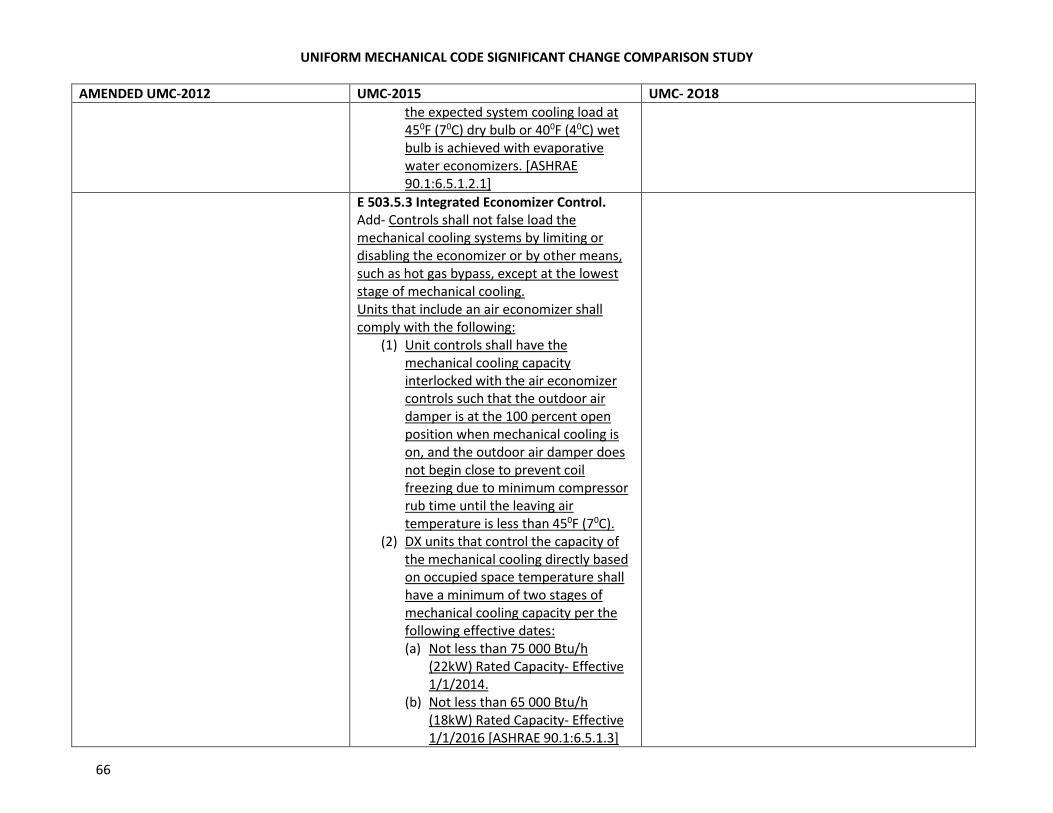
UNIFORM MECHANICAL CODE SIGNIFICANT CHANGE COMPARISON STUDY
66
AMENDED UMC-2012 UMC-2015 UMC- 2O18
the expected system cooling load at
450F (70C) dry bulb or 400F (40C) wet
bulb is achieved with evaporative
water economizers. [ASHRAE
90.1:6.5.1.2.1]
E 503.5.3 Integrated Economizer Control.
Add- Controls shall not false load the
mechanical cooling systems by limiting or
disabling the economizer or by other means,
such as hot gas bypass, except at the lowest
stage of mechanical cooling.
Units that include an air economizer shall
comply with the following:
(1) Unit controls shall have the
mechanical cooling capacity
interlocked with the air economizer
controls such that the outdoor air
damper is at the 100 percent open
position when mechanical cooling is
on, and the outdoor air damper does
not begin close to prevent coil
freezing due to minimum compressor
rub time until the leaving air
temperature is less than 450F (70C).
(2) DX units that control the capacity of
the mechanical cooling directly based
on occupied space temperature shall
have a minimum of two stages of
mechanical cooling capacity per the
following effective dates:
(a) Not less than 75 000 Btu/h
(22kW) Rated Capacity- Effective
1/1/2014.
(b) Not less than 65 000 Btu/h
(18kW) Rated Capacity- Effective
1/1/2016 [ASHRAE 90.1:6.5.1.3]
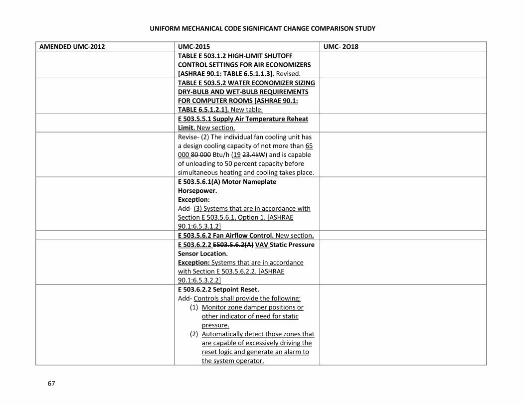
UNIFORM MECHANICAL CODE SIGNIFICANT CHANGE COMPARISON STUDY
67
AMENDED UMC-2012 UMC-2015 UMC- 2O18
TABLE E 503.1.2 HIGH-LIMIT SHUTOFF
CONTROL SETTINGS FOR AIR ECONOMIZERS
[ASHRAE 90.1: TABLE 6.5.1.1.3]. Revised.
TABLE E 503.5.2 WATER ECONOMIZER SIZING
DRY-BULB AND WET-BULB REQUIREMENTS
FOR COMPUTER ROOMS [ASHRAE 90.1:
TABLE 6.5.1.2.1]. New table.
E 503.5.5.1 Supply Air Temperature Reheat
Limit. New section.
Revise- (2) The individual fan cooling unit has
a design cooling capacity of not more than 65
000 80 000 Btu/h (19 23.4kW) and is capable
of unloading to 50 percent capacity before
simultaneous heating and cooling takes place.
E 503.5.6.1(A) Motor Nameplate
Horsepower.
Exception:
Add- (3) Systems that are in accordance with
Section E 503.5.6.1, Option 1. [ASHRAE
90.1:6.5.3.1.2]
E 503.5.6.2 Fan Airflow Control. New section.
E 503.6.2.2 E503.5.6.2(A) VAV Static Pressure
Sensor Location.
Exception: Systems that are in accordance
with Section E 503.5.6.2.2. [ASHRAE
90.1:6.5.3.2.2]
E 503.6.2.2 Setpoint Reset.
Add- Controls shall provide the following:
(1) Monitor zone damper positions or
other indicator of need for static
pressure.
(2) Automatically detect those zones that
are capable of excessively driving the
reset logic and generate an alarm to
the system operator.
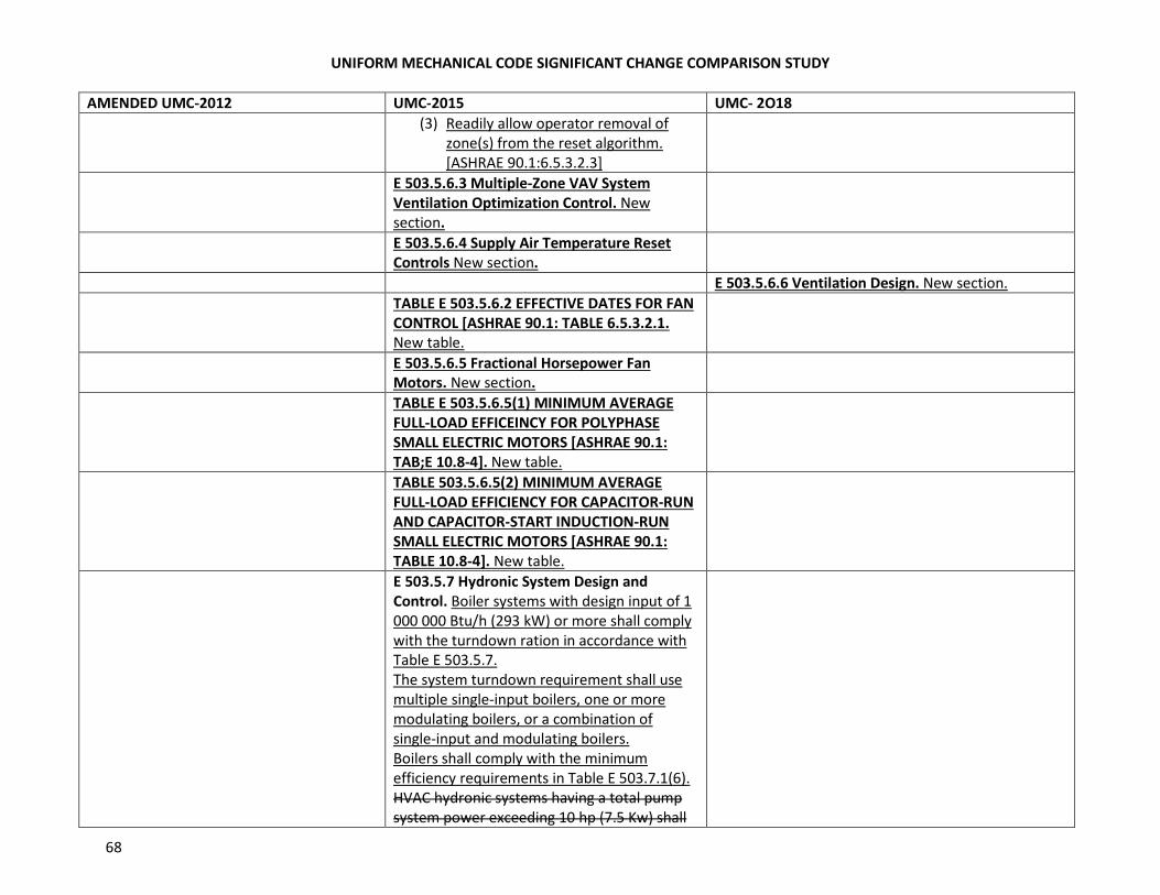
UNIFORM MECHANICAL CODE SIGNIFICANT CHANGE COMPARISON STUDY
68
AMENDED UMC-2012 UMC-2015 UMC- 2O18
(3) Readily allow operator removal of
zone(s) from the reset algorithm.
[ASHRAE 90.1:6.5.3.2.3]
E 503.5.6.3 Multiple-Zone VAV System
Ventilation Optimization Control. New
section.
E 503.5.6.4 Supply Air Temperature Reset
Controls New section.
E 503.5.6.6 Ventilation Design. New section.
TABLE E 503.5.6.2 EFFECTIVE DATES FOR FAN
CONTROL [ASHRAE 90.1: TABLE 6.5.3.2.1.
New table.
E 503.5.6.5 Fractional Horsepower Fan
Motors. New section.
TABLE E 503.5.6.5(1) MINIMUM AVERAGE
FULL-LOAD EFFICEINCY FOR POLYPHASE
SMALL ELECTRIC MOTORS [ASHRAE 90.1:
TAB;E 10.8-4]. New table.
TABLE 503.5.6.5(2) MINIMUM AVERAGE
FULL-LOAD EFFICIENCY FOR CAPACITOR-RUN
AND CAPACITOR-START INDUCTION-RUN
SMALL ELECTRIC MOTORS [ASHRAE 90.1:
TABLE 10.8-4]. New table.
E 503.5.7 Hydronic System Design and
Control. Boiler systems with design input of 1
000 000 Btu/h (293 kW) or more shall comply
with the turndown ration in accordance with
Table E 503.5.7.
The system turndown requirement shall use
multiple single-input boilers, one or more
modulating boilers, or a combination of
single-input and modulating boilers.
Boilers shall comply with the minimum
efficiency requirements in Table E 503.7.1(6).
HVAC hydronic systems having a total pump
system power exceeding 10 hp (7.5 Kw) shall
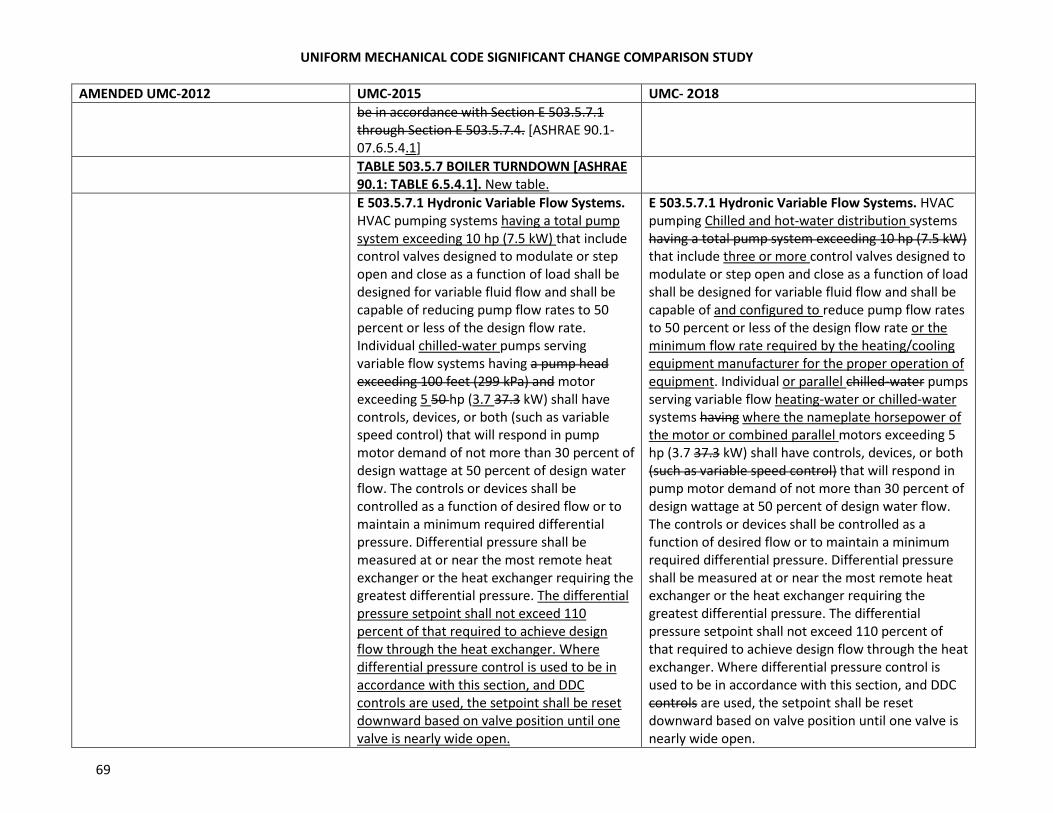
UNIFORM MECHANICAL CODE SIGNIFICANT CHANGE COMPARISON STUDY
69
AMENDED UMC-2012 UMC-2015 UMC- 2O18
be in accordance with Section E 503.5.7.1
through Section E 503.5.7.4. [ASHRAE 90.1-
07.6.5.4.1]
TABLE 503.5.7 BOILER TURNDOWN [ASHRAE
90.1: TABLE 6.5.4.1]. New table.
E 503.5.7.1 Hydronic Variable Flow Systems.
HVAC pumping systems having a total pump
system exceeding 10 hp (7.5 kW) that include
control valves designed to modulate or step
open and close as a function of load shall be
designed for variable fluid flow and shall be
capable of reducing pump flow rates to 50
percent or less of the design flow rate.
Individual chilled-water pumps serving
variable flow systems having a pump head
exceeding 100 feet (299 kPa) and motor
exceeding 5 50 hp (3.7 37.3 kW) shall have
controls, devices, or both (such as variable
speed control) that will respond in pump
motor demand of not more than 30 percent of
design wattage at 50 percent of design water
flow. The controls or devices shall be
controlled as a function of desired flow or to
maintain a minimum required differential
pressure. Differential pressure shall be
measured at or near the most remote heat
exchanger or the heat exchanger requiring the
greatest differential pressure. The differential
pressure setpoint shall not exceed 110
percent of that required to achieve design
flow through the heat exchanger. Where
differential pressure control is used to be in
accordance with this section, and DDC
controls are used, the setpoint shall be reset
downward based on valve position until one
valve is nearly wide open.
E 503.5.7.1 Hydronic Variable Flow Systems. HVAC
pumping Chilled and hot-water distribution systems
having a total pump system exceeding 10 hp (7.5 kW)
that include three or more control valves designed to
modulate or step open and close as a function of load
shall be designed for variable fluid flow and shall be
capable of and configured to reduce pump flow rates
to 50 percent or less of the design flow rate or the
minimum flow rate required by the heating/cooling
equipment manufacturer for the proper operation of
equipment. Individual or parallel chilled-water pumps
serving variable flow heating-water or chilled-water
systems having where the nameplate horsepower of
the motor or combined parallel motors exceeding 5
hp (3.7 37.3 kW) shall have controls, devices, or both
(such as variable speed control) that will respond in
pump motor demand of not more than 30 percent of
design wattage at 50 percent of design water flow.
The controls or devices shall be controlled as a
function of desired flow or to maintain a minimum
required differential pressure. Differential pressure
shall be measured at or near the most remote heat
exchanger or the heat exchanger requiring the
greatest differential pressure. The differential
pressure setpoint shall not exceed 110 percent of
that required to achieve design flow through the heat
exchanger. Where differential pressure control is
used to be in accordance with this section, and DDC
controls are used, the setpoint shall be reset
downward based on valve position until one valve is
nearly wide open.
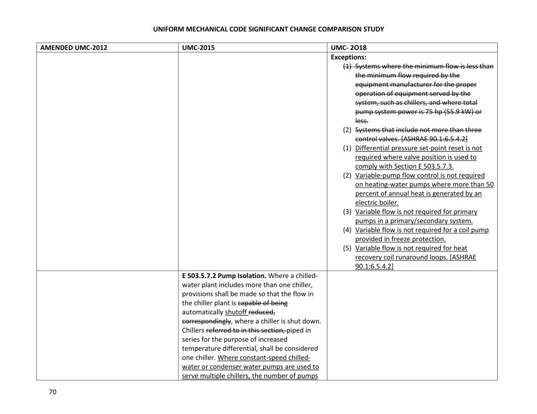
UNIFORM MECHANICAL CODE SIGNIFICANT CHANGE COMPARISON STUDY
70
AMENDED UMC-2012 UMC-2015 UMC- 2O18
Exceptions:
(1) Systems where the minimum flow is less than
the minimum flow required by the
equipment manufacturer for the proper
operation of equipment served by the
system, such as chillers, and where total
pump system power is 75 hp (55.9 kW) or
less.
(2) Systems that include not more than three
control valves. [ASHRAE 90.1:6.5.4.2]
(1) Differential pressure set-point reset is not
required where valve position is used to
comply with Section E 503.5.7.3.
(2) Variable-pump flow control is not required
on heating-water pumps where more than 50
percent of annual heat is generated by an
electric boiler.
(3) Variable flow is not required for primary
pumps in a primary/secondary system.
(4) Variable flow is not required for a coil pump
provided in freeze protection.
(5) Variable flow is not required for heat
recovery coil runaround loops. [ASHRAE
90.1:6.5.4.2]
E 503.5.7.2 Pump Isolation. Where a chilled-
water plant includes more than one chiller,
provisions shall be made so that the flow in
the chiller plant is capable of being
automatically shutoff reduced,
correspondingly, where a chiller is shut down.
Chillers referred to in this section, piped in
series for the purpose of increased
temperature differential, shall be considered
one chiller. Where constant-speed chilled-
water or condenser water pumps are used to
serve multiple chillers, the number of pumps
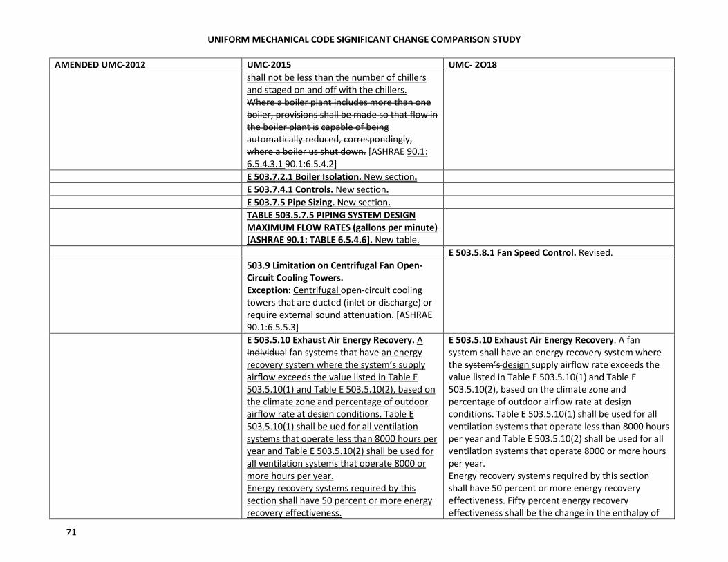
UNIFORM MECHANICAL CODE SIGNIFICANT CHANGE COMPARISON STUDY
71
AMENDED UMC-2012 UMC-2015 UMC- 2O18
shall not be less than the number of chillers
and staged on and off with the chillers.
Where a boiler plant includes more than one
boiler, provisions shall be made so that flow in
the boiler plant is capable of being
automatically reduced, correspondingly,
where a boiler us shut down. [ASHRAE 90.1:
6.5.4.3.1 90.1:6.5.4.2]
E 503.7.2.1 Boiler Isolation. New section.
E 503.7.4.1 Controls. New section.
E 503.7.5 Pipe Sizing. New section.
TABLE 503.5.7.5 PIPING SYSTEM DESIGN
MAXIMUM FLOW RATES (gallons per minute)
[ASHRAE 90.1: TABLE 6.5.4.6]. New table.
E 503.5.8.1 Fan Speed Control. Revised.
503.9 Limitation on Centrifugal Fan Open-
Circuit Cooling Towers.
Exception: Centrifugal open-circuit cooling
towers that are ducted (inlet or discharge) or
require external sound attenuation. [ASHRAE
90.1:6.5.5.3]
E 503.5.10 Exhaust Air Energy Recovery. A
Individual fan systems that have an energy
recovery system where the system’s supply
airflow exceeds the value listed in Table E
503.5.10(1) and Table E 503.5.10(2), based on
the climate zone and percentage of outdoor
airflow rate at design conditions. Table E
503.5.10(1) shall be ued for all ventilation
systems that operate less than 8000 hours per
year and Table E 503.5.10(2) shall be used for
all ventilation systems that operate 8000 or
more hours per year.
Energy recovery systems required by this
section shall have 50 percent or more energy
recovery effectiveness.
E 503.5.10 Exhaust Air Energy Recovery. A fan
system shall have an energy recovery system where
the system’s design supply airflow rate exceeds the
value listed in Table E 503.5.10(1) and Table E
503.5.10(2), based on the climate zone and
percentage of outdoor airflow rate at design
conditions. Table E 503.5.10(1) shall be used for all
ventilation systems that operate less than 8000 hours
per year and Table E 503.5.10(2) shall be used for all
ventilation systems that operate 8000 or more hours
per year.
Energy recovery systems required by this section
shall have 50 percent or more energy recovery
effectiveness. Fifty percent energy recovery
effectiveness shall be the change in the enthalpy of
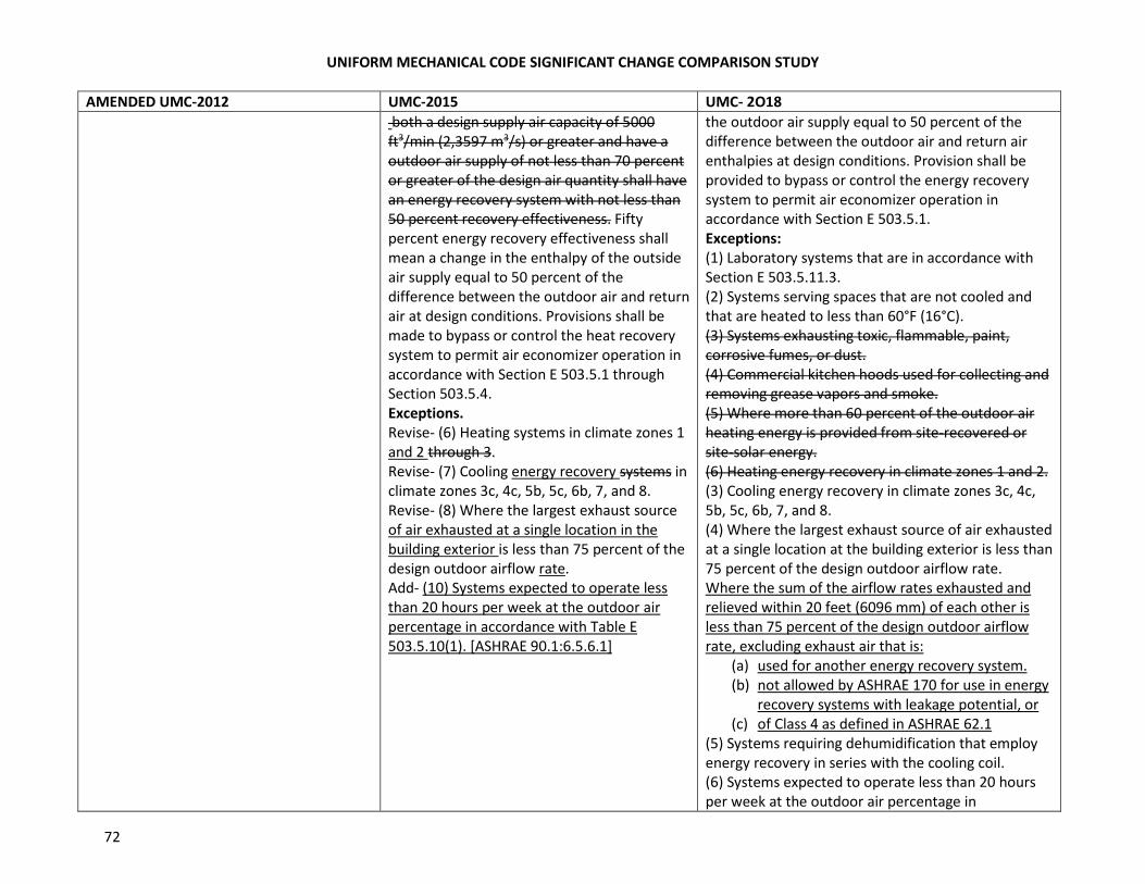
UNIFORM MECHANICAL CODE SIGNIFICANT CHANGE COMPARISON STUDY
72
AMENDED UMC-2012 UMC-2015 UMC- 2O18
both a design supply air capacity of 5000
ft3/min (2,3597 m3/s) or greater and have a
outdoor air supply of not less than 70 percent
or greater of the design air quantity shall have
an energy recovery system with not less than
50 percent recovery effectiveness. Fifty
percent energy recovery effectiveness shall
mean a change in the enthalpy of the outside
air supply equal to 50 percent of the
difference between the outdoor air and return
air at design conditions. Provisions shall be
made to bypass or control the heat recovery
system to permit air economizer operation in
accordance with Section E 503.5.1 through
Section 503.5.4.
Exceptions.
Revise- (6) Heating systems in climate zones 1
and 2 through 3.
Revise- (7) Cooling energy recovery systems in
climate zones 3c, 4c, 5b, 5c, 6b, 7, and 8.
Revise- (8) Where the largest exhaust source
of air exhausted at a single location in the
building exterior is less than 75 percent of the
design outdoor airflow rate.
Add- (10) Systems expected to operate less
than 20 hours per week at the outdoor air
percentage in accordance with Table E
503.5.10(1). [ASHRAE 90.1:6.5.6.1]
the outdoor air supply equal to 50 percent of the
difference between the outdoor air and return air
enthalpies at design conditions. Provision shall be
provided to bypass or control the energy recovery
system to permit air economizer operation in
accordance with Section E 503.5.1.
Exceptions:
(1) Laboratory systems that are in accordance with
Section E 503.5.11.3.
(2) Systems serving spaces that are not cooled and
that are heated to less than 60°F (16°C).
(3) Systems exhausting toxic, flammable, paint,
corrosive fumes, or dust.
(4) Commercial kitchen hoods used for collecting and
removing grease vapors and smoke.
(5) Where more than 60 percent of the outdoor air
heating energy is provided from site-recovered or
site-solar energy.
(6) Heating energy recovery in climate zones 1 and 2.
(3) Cooling energy recovery in climate zones 3c, 4c,
5b, 5c, 6b, 7, and 8.
(4) Where the largest exhaust source of air exhausted
at a single location at the building exterior is less than
75 percent of the design outdoor airflow rate.
Where the sum of the airflow rates exhausted and
relieved within 20 feet (6096 mm) of each other is
less than 75 percent of the design outdoor airflow
rate, excluding exhaust air that is:
(a) used for another energy recovery system.
(b) not allowed by ASHRAE 170 for use in energy
recovery systems with leakage potential, or
(c) of Class 4 as defined in ASHRAE 62.1
(5) Systems requiring dehumidification that employ
energy recovery in series with the cooling coil.
(6) Systems expected to operate less than 20 hours
per week at the outdoor air percentage in
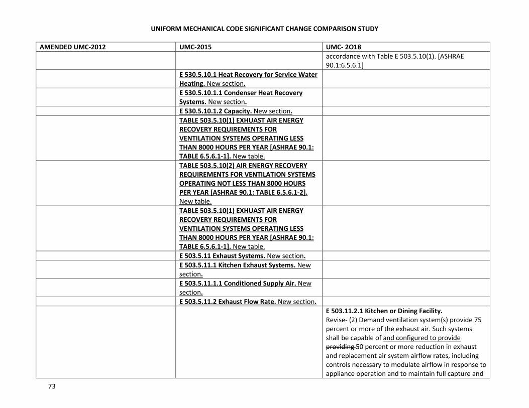
UNIFORM MECHANICAL CODE SIGNIFICANT CHANGE COMPARISON STUDY
73
AMENDED UMC-2012 UMC-2015 UMC- 2O18
accordance with Table E 503.5.10(1). [ASHRAE
90.1:6.5.6.1]
E 530.5.10.1 Heat Recovery for Service Water
Heating. New section.
E 530.5.10.1.1 Condenser Heat Recovery
Systems. New section.
E 530.5.10.1.2 Capacity. New section.
TABLE 503.5.10(1) EXHUAST AIR ENERGY
RECOVERY REQUIREMENTS FOR
VENTILATION SYSTEMS OPERATING LESS
THAN 8000 HOURS PER YEAR [ASHRAE 90.1:
TABLE 6.5.6.1-1]. New table.
TABLE 503.5.10(2) AIR ENERGY RECOVERY
REQUIREMENTS FOR VENTILATION SYSTEMS
OPERATING NOT LESS THAN 8000 HOURS
PER YEAR [ASHRAE 90.1: TABLE 6.5.6.1-2].
New table.
TABLE 503.5.10(1) EXHUAST AIR ENERGY
RECOVERY REQUIREMENTS FOR
VENTILATION SYSTEMS OPERATING LESS
THAN 8000 HOURS PER YEAR [ASHRAE 90.1:
TABLE 6.5.6.1-1]. New table.
E 503.5.11 Exhaust Systems. New section.
E 503.5.11.1 Kitchen Exhaust Systems. New
section.
E 503.5.11.1.1 Conditioned Supply Air. New
section.
E 503.5.11.2 Exhaust Flow Rate. New section.
E 503.11.2.1 Kitchen or Dining Facility.
Revise- (2) Demand ventilation system(s) provide 75
percent or more of the exhaust air. Such systems
shall be capable of and configured to provide
providing 50 percent or more reduction in exhaust
and replacement air system airflow rates, including
controls necessary to modulate airflow in response to
appliance operation and to maintain full capture and
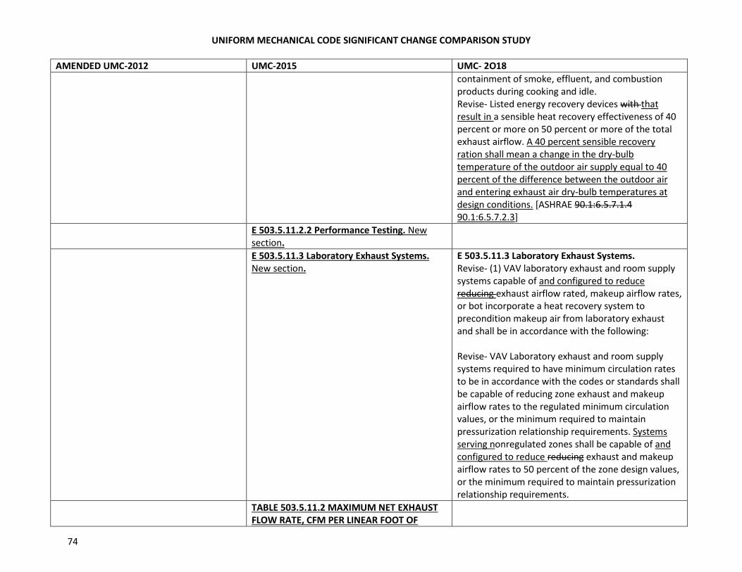
UNIFORM MECHANICAL CODE SIGNIFICANT CHANGE COMPARISON STUDY
74
AMENDED UMC-2012 UMC-2015 UMC- 2O18
containment of smoke, effluent, and combustion
products during cooking and idle.
Revise- Listed energy recovery devices with that
result in a sensible heat recovery effectiveness of 40
percent or more on 50 percent or more of the total
exhaust airflow. A 40 percent sensible recovery
ration shall mean a change in the dry-bulb
temperature of the outdoor air supply equal to 40
percent of the difference between the outdoor air
and entering exhaust air dry-bulb temperatures at
design conditions. [ASHRAE 90.1:6.5.7.1.4
90.1:6.5.7.2.3]
E 503.5.11.2.2 Performance Testing. New
section.
E 503.5.11.3 Laboratory Exhaust Systems.
New section.
E 503.5.11.3 Laboratory Exhaust Systems.
Revise- (1) VAV laboratory exhaust and room supply
systems capable of and configured to reduce
reducing exhaust airflow rated, makeup airflow rates,
or bot incorporate a heat recovery system to
precondition makeup air from laboratory exhaust
and shall be in accordance with the following:
Revise- VAV Laboratory exhaust and room supply
systems required to have minimum circulation rates
to be in accordance with the codes or standards shall
be capable of reducing zone exhaust and makeup
airflow rates to the regulated minimum circulation
values, or the minimum required to maintain
pressurization relationship requirements. Systems
serving nonregulated zones shall be capable of and
configured to reduce reducing exhaust and makeup
airflow rates to 50 percent of the zone design values,
or the minimum required to maintain pressurization
relationship requirements.
TABLE 503.5.11.2 MAXIMUM NET EXHAUST
FLOW RATE, CFM PER LINEAR FOOT OF
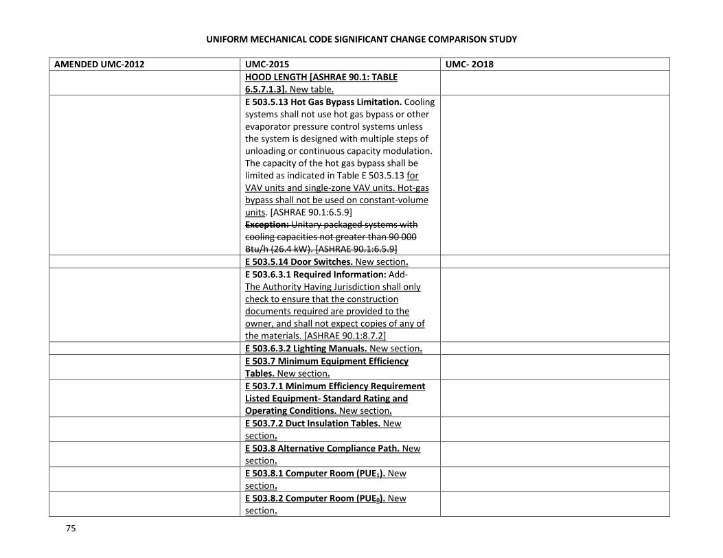
UNIFORM MECHANICAL CODE SIGNIFICANT CHANGE COMPARISON STUDY
75
AMENDED UMC-2012 UMC-2015 UMC- 2O18
HOOD LENGTH [ASHRAE 90.1: TABLE
6.5.7.1.3]. New table.
E 503.5.13 Hot Gas Bypass Limitation. Cooling
systems shall not use hot gas bypass or other
evaporator pressure control systems unless
the system is designed with multiple steps of
unloading or continuous capacity modulation.
The capacity of the hot gas bypass shall be
limited as indicated in Table E 503.5.13 for
VAV units and single-zone VAV units. Hot-gas
bypass shall not be used on constant-volume
units. [ASHRAE 90.1:6.5.9]
Exception: Unitary packaged systems with
cooling capacities not greater than 90 000
Btu/h (26.4 kW). [ASHRAE 90.1:6.5.9]
E 503.5.14 Door Switches. New section.
E 503.6.3.1 Required Information: Add-
The Authority Having Jurisdiction shall only
check to ensure that the construction
documents required are provided to the
owner, and shall not expect copies of any of
the materials. [ASHRAE 90.1:8.7.2]
E 503.6.3.2 Lighting Manuals. New section.
E 503.7 Minimum Equipment Efficiency
Tables. New section.
E 503.7.1 Minimum Efficiency Requirement
Listed Equipment- Standard Rating and
Operating Conditions. New section.
E 503.7.2 Duct Insulation Tables. New
section.
E 503.8 Alternative Compliance Path. New
section.
E 503.8.1 Computer Room (PUE1). New
section.
E 503.8.2 Computer Room (PUE0). New
section.
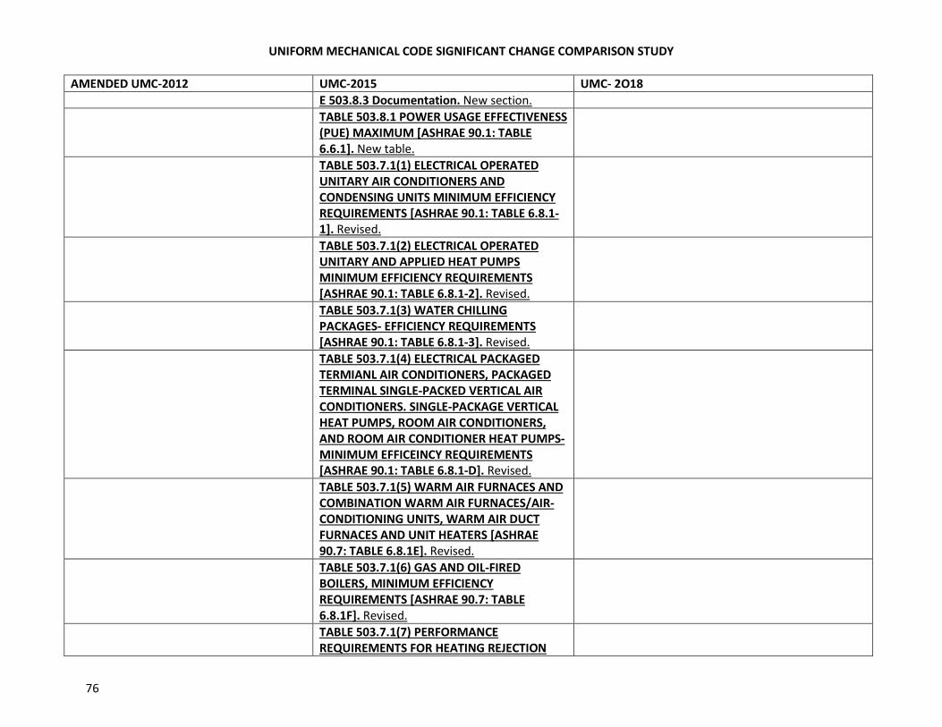
UNIFORM MECHANICAL CODE SIGNIFICANT CHANGE COMPARISON STUDY
76
AMENDED UMC-2012 UMC-2015 UMC- 2O18
E 503.8.3 Documentation. New section.
TABLE 503.8.1 POWER USAGE EFFECTIVENESS
(PUE) MAXIMUM [ASHRAE 90.1: TABLE
6.6.1]. New table.
TABLE 503.7.1(1) ELECTRICAL OPERATED
UNITARY AIR CONDITIONERS AND
CONDENSING UNITS MINIMUM EFFICIENCY
REQUIREMENTS [ASHRAE 90.1: TABLE 6.8.1-
1]. Revised.
TABLE 503.7.1(2) ELECTRICAL OPERATED
UNITARY AND APPLIED HEAT PUMPS
MINIMUM EFFICIENCY REQUIREMENTS
[ASHRAE 90.1: TABLE 6.8.1-2]. Revised.
TABLE 503.7.1(3) WATER CHILLING
PACKAGES- EFFICIENCY REQUIREMENTS
[ASHRAE 90.1: TABLE 6.8.1-3]. Revised.
TABLE 503.7.1(4) ELECTRICAL PACKAGED
TERMIANL AIR CONDITIONERS, PACKAGED
TERMINAL SINGLE-PACKED VERTICAL AIR
CONDITIONERS. SINGLE-PACKAGE VERTICAL
HEAT PUMPS, ROOM AIR CONDITIONERS,
AND ROOM AIR CONDITIONER HEAT PUMPS-
MINIMUM EFFICEINCY REQUIREMENTS
[ASHRAE 90.1: TABLE 6.8.1-D]. Revised.
TABLE 503.7.1(5) WARM AIR FURNACES AND
COMBINATION WARM AIR FURNACES/AIR-
CONDITIONING UNITS, WARM AIR DUCT
FURNACES AND UNIT HEATERS [ASHRAE
90.7: TABLE 6.8.1E]. Revised.
TABLE 503.7.1(6) GAS AND OIL-FIRED
BOILERS, MINIMUM EFFICIENCY
REQUIREMENTS [ASHRAE 90.7: TABLE
6.8.1F]. Revised.
TABLE 503.7.1(7) PERFORMANCE
REQUIREMENTS FOR HEATING REJECTION
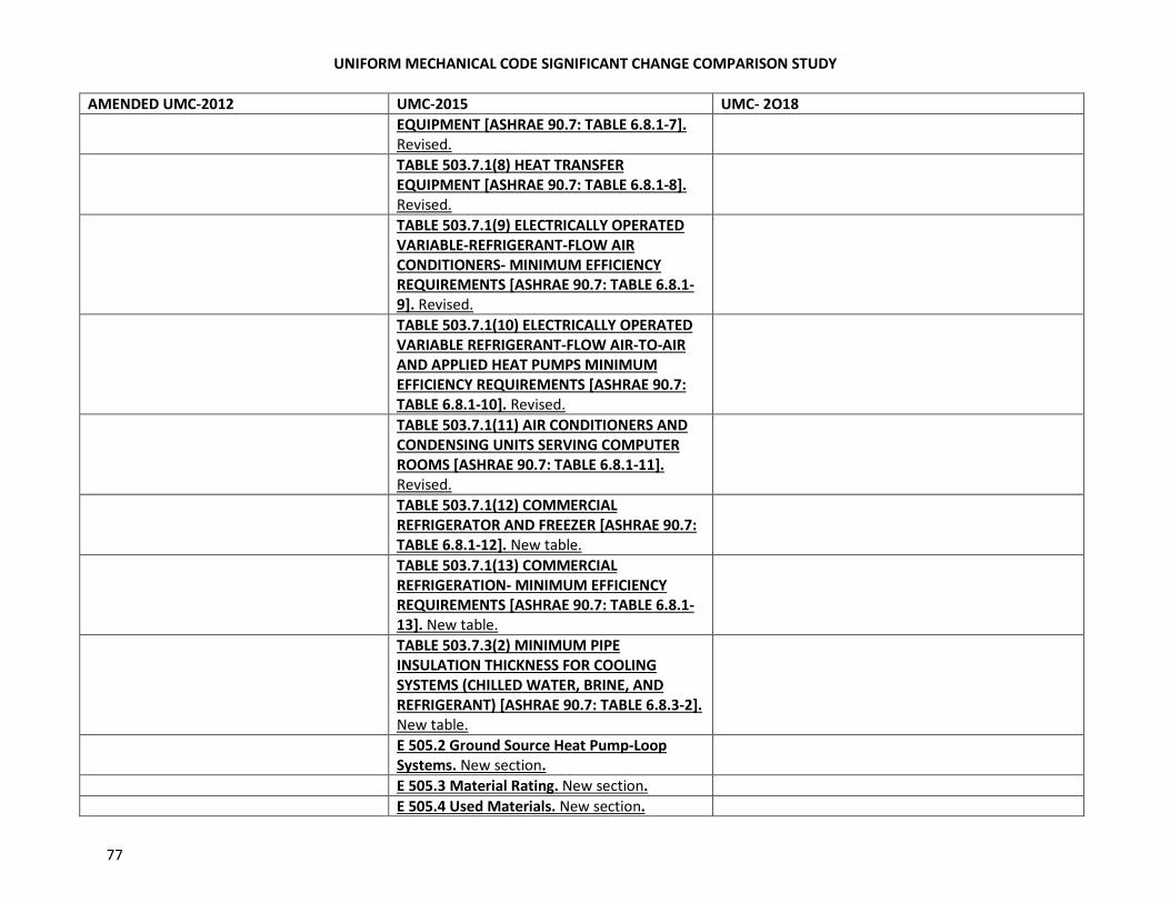
UNIFORM MECHANICAL CODE SIGNIFICANT CHANGE COMPARISON STUDY
77
AMENDED UMC-2012 UMC-2015 UMC- 2O18
EQUIPMENT [ASHRAE 90.7: TABLE 6.8.1-7].
Revised.
TABLE 503.7.1(8) HEAT TRANSFER
EQUIPMENT [ASHRAE 90.7: TABLE 6.8.1-8].
Revised.
TABLE 503.7.1(9) ELECTRICALLY OPERATED
VARIABLE-REFRIGERANT-FLOW AIR
CONDITIONERS- MINIMUM EFFICIENCY
REQUIREMENTS [ASHRAE 90.7: TABLE 6.8.1-
9]. Revised.
TABLE 503.7.1(10) ELECTRICALLY OPERATED
VARIABLE REFRIGERANT-FLOW AIR-TO-AIR
AND APPLIED HEAT PUMPS MINIMUM
EFFICIENCY REQUIREMENTS [ASHRAE 90.7:
TABLE 6.8.1-10]. Revised.
TABLE 503.7.1(11) AIR CONDITIONERS AND
CONDENSING UNITS SERVING COMPUTER
ROOMS [ASHRAE 90.7: TABLE 6.8.1-11].
Revised.
TABLE 503.7.1(12) COMMERCIAL
REFRIGERATOR AND FREEZER [ASHRAE 90.7:
TABLE 6.8.1-12]. New table.
TABLE 503.7.1(13) COMMERCIAL
REFRIGERATION- MINIMUM EFFICIENCY
REQUIREMENTS [ASHRAE 90.7: TABLE 6.8.1-
13]. New table.
TABLE 503.7.3(2) MINIMUM PIPE
INSULATION THICKNESS FOR COOLING
SYSTEMS (CHILLED WATER, BRINE, AND
REFRIGERANT) [ASHRAE 90.7: TABLE 6.8.3-2].
New table.
E 505.2 Ground Source Heat Pump-Loop
Systems. New section.
E 505.3 Material Rating. New section.
E 505.4 Used Materials. New section.
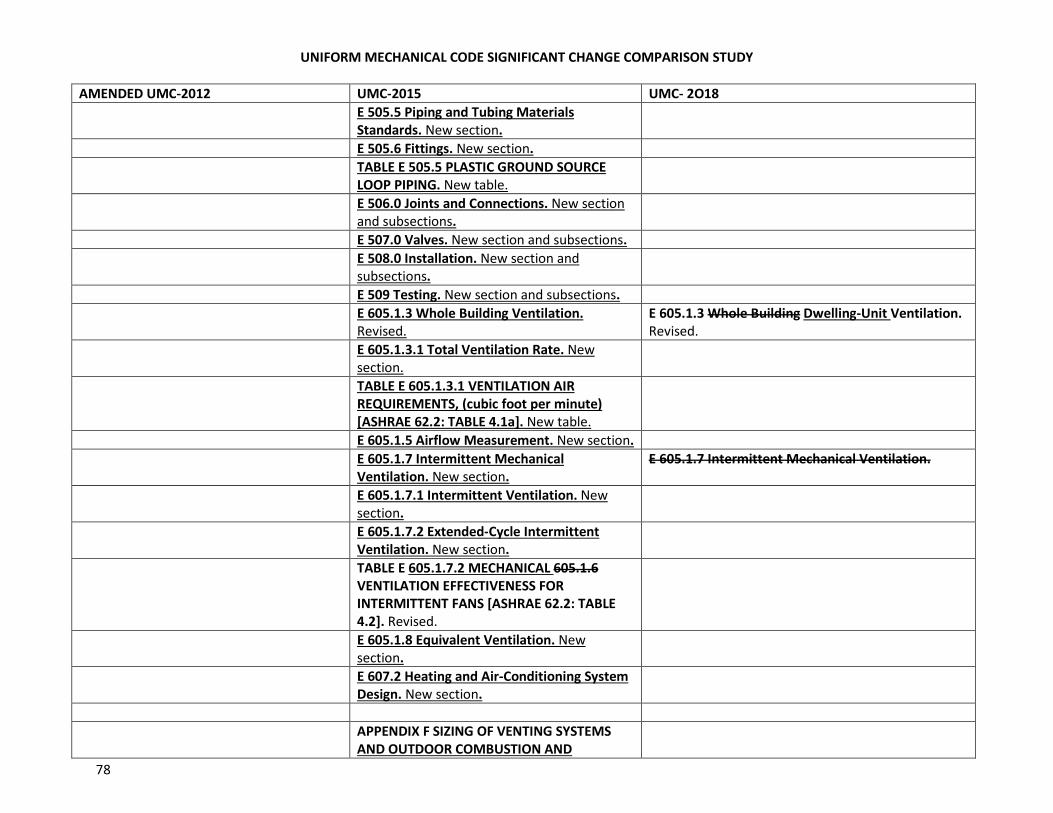
UNIFORM MECHANICAL CODE SIGNIFICANT CHANGE COMPARISON STUDY
78
AMENDED UMC-2012 UMC-2015 UMC- 2O18
E 505.5 Piping and Tubing Materials
Standards. New section.
E 505.6 Fittings. New section.
TABLE E 505.5 PLASTIC GROUND SOURCE
LOOP PIPING. New table.
E 506.0 Joints and Connections. New section
and subsections.
E 507.0 Valves. New section and subsections.
E 508.0 Installation. New section and
subsections.
E 509 Testing. New section and subsections.
E 605.1.3 Whole Building Ventilation.
Revised.
E 605.1.3 Whole Building Dwelling-Unit Ventilation.
Revised.
E 605.1.3.1 Total Ventilation Rate. New
section.
TABLE E 605.1.3.1 VENTILATION AIR
REQUIREMENTS, (cubic foot per minute)
[ASHRAE 62.2: TABLE 4.1a]. New table.
E 605.1.5 Airflow Measurement. New section.
E 605.1.7 Intermittent Mechanical
Ventilation. New section.
E 605.1.7 Intermittent Mechanical Ventilation.
E 605.1.7.1 Intermittent Ventilation. New
section.
E 605.1.7.2 Extended-Cycle Intermittent
Ventilation. New section.
TABLE E 605.1.7.2 MECHANICAL 605.1.6
VENTILATION EFFECTIVENESS FOR
INTERMITTENT FANS [ASHRAE 62.2: TABLE
4.2]. Revised.
E 605.1.8 Equivalent Ventilation. New
section.
E 607.2 Heating and Air-Conditioning System
Design. New section.
APPENDIX F SIZING OF VENTING SYSTEMS
AND OUTDOOR COMBUSTION AND
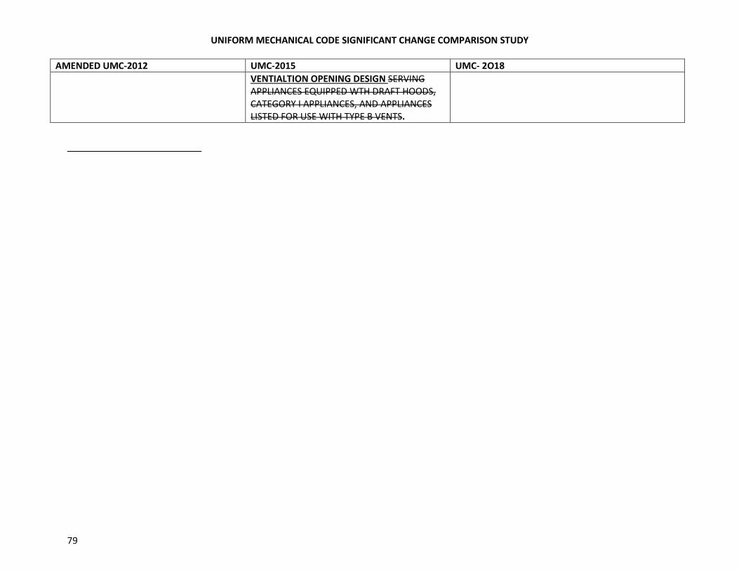
UNIFORM MECHANICAL CODE SIGNIFICANT CHANGE COMPARISON STUDY
79
AMENDED UMC-2012 UMC-2015 UMC- 2O18
VENTIALTION OPENING DESIGN SERVING
APPLIANCES EQUIPPED WTH DRAFT HOODS,
CATEGORY I APPLIANCES, AND APPLIANCES
LISTED FOR USE WITH TYPE B VENTS.