UM1458 User manual - STMicroelectronics · This demonstration board is a smartplug based on the ......
33
November 2011 Doc ID 022127 Rev 1 1/33 UM1458 User manual STEVAL-IHP002V2: PLM smartplugV2 hardware Introduction This demonstration board is a smartplug based on the STM32F10x microcontroller, ST7540 PLM, and STPM01 energy metering ICs. The board is a node of a PLM network which allows the final user to monitor and manage the plugged load energy consumption. The board has been developed to provide a guideline on how to build a home/building automation subsystem for energy management. It is designed to fit the dimensions of a standard box for wall installation and easy integration into home/building electrical plants. The current, power, energy and other information related to the electrical load connected to the smartplug board are sent to a PLM data concentrator through the home/building PLM network. The board includes the following functions which are illustrated in the block diagram of Figure 1: ■ Energy measurement ■ Power line communication up to 4.8 kbps ■ RS232 connectivity by extension connector ■ Load driver with relay Figure 1. PLM smartplugV2 block diagram www.st.com
Transcript of UM1458 User manual - STMicroelectronics · This demonstration board is a smartplug based on the ......

November 2011 Doc ID 022127 Rev 1 1/33
UM1458User manual
STEVAL-IHP002V2: PLM smartplugV2 hardware
IntroductionThis demonstration board is a smartplug based on the STM32F10x microcontroller, ST7540 PLM, and STPM01 energy metering ICs. The board is a node of a PLM network which allows the final user to monitor and manage the plugged load energy consumption.
The board has been developed to provide a guideline on how to build a home/building automation subsystem for energy management. It is designed to fit the dimensions of a standard box for wall installation and easy integration into home/building electrical plants. The current, power, energy and other information related to the electrical load connected to the smartplug board are sent to a PLM data concentrator through the home/building PLM network. The board includes the following functions which are illustrated in the block diagram of Figure 1:
■ Energy measurement
■ Power line communication up to 4.8 kbps
■ RS232 connectivity by extension connector
■ Load driver with relay
Figure 1. PLM smartplugV2 block diagram
www.st.com
Contents UM1458
2/33 Doc ID 022127 Rev 1
Contents
1 Overview . . . . . . . . . . . . . . . . . . . . . . . . . . . . . . . . . . . . . . . . . . . . . . . . . . 5
1.1 Recommended reading . . . . . . . . . . . . . . . . . . . . . . . . . . . . . . . . . . . . . . . 5
1.2 Safety precautions . . . . . . . . . . . . . . . . . . . . . . . . . . . . . . . . . . . . . . . . . . . 5
1.3 Getting technical support . . . . . . . . . . . . . . . . . . . . . . . . . . . . . . . . . . . . . . 5
1.4 Package list . . . . . . . . . . . . . . . . . . . . . . . . . . . . . . . . . . . . . . . . . . . . . . . . 6
2 PLM smartplug demonstration board components . . . . . . . . . . . . . . . . 7
2.1 Microcontroller . . . . . . . . . . . . . . . . . . . . . . . . . . . . . . . . . . . . . . . . . . . . . . 7
2.2 Debug . . . . . . . . . . . . . . . . . . . . . . . . . . . . . . . . . . . . . . . . . . . . . . . . . . . . . 7
2.3 Reset . . . . . . . . . . . . . . . . . . . . . . . . . . . . . . . . . . . . . . . . . . . . . . . . . . . . . 7
2.4 Power supplies . . . . . . . . . . . . . . . . . . . . . . . . . . . . . . . . . . . . . . . . . . . . . . 7
2.5 Power line communication . . . . . . . . . . . . . . . . . . . . . . . . . . . . . . . . . . . . . 7
2.6 Energy measurement . . . . . . . . . . . . . . . . . . . . . . . . . . . . . . . . . . . . . . . . . 8
2.7 Load drivers . . . . . . . . . . . . . . . . . . . . . . . . . . . . . . . . . . . . . . . . . . . . . . . . 9
2.8 USART communication . . . . . . . . . . . . . . . . . . . . . . . . . . . . . . . . . . . . . . . 9
2.9 Status LEDs . . . . . . . . . . . . . . . . . . . . . . . . . . . . . . . . . . . . . . . . . . . . . . . 10
2.10 Jumpers . . . . . . . . . . . . . . . . . . . . . . . . . . . . . . . . . . . . . . . . . . . . . . . . . . 10
2.10.1 Jumper placement . . . . . . . . . . . . . . . . . . . . . . . . . . . . . . . . . . . . . . . . . 10
2.10.2 Jumper positions . . . . . . . . . . . . . . . . . . . . . . . . . . . . . . . . . . . . . . . . . . 11
2.10.3 Jumper description and default value . . . . . . . . . . . . . . . . . . . . . . . . . . 11
2.11 Pushbutton description . . . . . . . . . . . . . . . . . . . . . . . . . . . . . . . . . . . . . . . 11
2.12 Connector description . . . . . . . . . . . . . . . . . . . . . . . . . . . . . . . . . . . . . . . 12
2.12.1 STM32 JTAG connector . . . . . . . . . . . . . . . . . . . . . . . . . . . . . . . . . . . . . 12
2.13 Energy meter IC calibration connector . . . . . . . . . . . . . . . . . . . . . . . . . . . 13
3 Board configuration . . . . . . . . . . . . . . . . . . . . . . . . . . . . . . . . . . . . . . . . 14
3.1 SPTM01 calibration configuration . . . . . . . . . . . . . . . . . . . . . . . . . . . . . . 14
4 Bill of material and schematics . . . . . . . . . . . . . . . . . . . . . . . . . . . . . . . 15
5 Revision history . . . . . . . . . . . . . . . . . . . . . . . . . . . . . . . . . . . . . . . . . . . 32

UM1458 List of tables
Doc ID 022127 Rev 1 3/33
List of tables
Table 1. STM32 resources – ST7540 function mapping . . . . . . . . . . . . . . . . . . . . . . . . . . . . . . . . . . 8Table 2. STM32 resources – STPM01 function mapping . . . . . . . . . . . . . . . . . . . . . . . . . . . . . . . . . . 9Table 3. STM32 resources – RS232 function mapping . . . . . . . . . . . . . . . . . . . . . . . . . . . . . . . . . . 10Table 4. LED description . . . . . . . . . . . . . . . . . . . . . . . . . . . . . . . . . . . . . . . . . . . . . . . . . . . . . . . . . 10Table 5. Jumper description . . . . . . . . . . . . . . . . . . . . . . . . . . . . . . . . . . . . . . . . . . . . . . . . . . . . . . . 11Table 6. Pushbutton description . . . . . . . . . . . . . . . . . . . . . . . . . . . . . . . . . . . . . . . . . . . . . . . . . . . . 11Table 7. Connector description. . . . . . . . . . . . . . . . . . . . . . . . . . . . . . . . . . . . . . . . . . . . . . . . . . . . . 12Table 8. JTAG connector pin description . . . . . . . . . . . . . . . . . . . . . . . . . . . . . . . . . . . . . . . . . . . . . 13Table 9. Energy meter calibration connector pin description . . . . . . . . . . . . . . . . . . . . . . . . . . . . . . 13Table 10. Bill of material . . . . . . . . . . . . . . . . . . . . . . . . . . . . . . . . . . . . . . . . . . . . . . . . . . . . . . . . . . . 15Table 11. Document revision history . . . . . . . . . . . . . . . . . . . . . . . . . . . . . . . . . . . . . . . . . . . . . . . . . 32

List of figures UM1458
4/33 Doc ID 022127 Rev 1
List of figures
Figure 1. PLM smartplugV2 block diagram . . . . . . . . . . . . . . . . . . . . . . . . . . . . . . . . . . . . . . . . . . . . . 1Figure 2. PLM smartplugV2 board . . . . . . . . . . . . . . . . . . . . . . . . . . . . . . . . . . . . . . . . . . . . . . . . . . . . 6Figure 3. Wiring diagram for monitored and controlled AC load . . . . . . . . . . . . . . . . . . . . . . . . . . . . . 8Figure 4. Wiring diagram for a controlled generic load and a monitored AC load . . . . . . . . . . . . . . . . 9Figure 5. Jumper placement . . . . . . . . . . . . . . . . . . . . . . . . . . . . . . . . . . . . . . . . . . . . . . . . . . . . . . . 10Figure 6. Jumper positions. . . . . . . . . . . . . . . . . . . . . . . . . . . . . . . . . . . . . . . . . . . . . . . . . . . . . . . . . 11Figure 7. Connector position . . . . . . . . . . . . . . . . . . . . . . . . . . . . . . . . . . . . . . . . . . . . . . . . . . . . . . . 12Figure 8. STM32 10-pin JTAG connector . . . . . . . . . . . . . . . . . . . . . . . . . . . . . . . . . . . . . . . . . . . . . 12Figure 9. Energy meter calibration connector . . . . . . . . . . . . . . . . . . . . . . . . . . . . . . . . . . . . . . . . . . 13Figure 10. Top page. . . . . . . . . . . . . . . . . . . . . . . . . . . . . . . . . . . . . . . . . . . . . . . . . . . . . . . . . . . . . . . 25Figure 11. Power supply section . . . . . . . . . . . . . . . . . . . . . . . . . . . . . . . . . . . . . . . . . . . . . . . . . . . . . 26Figure 12. USART expansion connector section . . . . . . . . . . . . . . . . . . . . . . . . . . . . . . . . . . . . . . . . . 27Figure 13. Power line modem section . . . . . . . . . . . . . . . . . . . . . . . . . . . . . . . . . . . . . . . . . . . . . . . . . 28Figure 14. MCU section . . . . . . . . . . . . . . . . . . . . . . . . . . . . . . . . . . . . . . . . . . . . . . . . . . . . . . . . . . . . 29Figure 15. STPM01 . . . . . . . . . . . . . . . . . . . . . . . . . . . . . . . . . . . . . . . . . . . . . . . . . . . . . . . . . . . . . . . 30Figure 16. Output drivers . . . . . . . . . . . . . . . . . . . . . . . . . . . . . . . . . . . . . . . . . . . . . . . . . . . . . . . . . . . 31
UM1458 Overview
Doc ID 022127 Rev 1 5/33
1 Overview
1.1 Recommended readingThis document describes how to configure and use the PLM smartplug demonstration board. Additional information can be found in the following documents:
● ST device datasheets referenced in this document
● Third party device datasheets
● AN3287 application note
● UM1459 user manual.
1.2 Safety precautionsThe board must be used only by expert technicians. Due to the high voltage (220 Vac) special care should be taken with regard to human safety.
There is no protection against accidental human contact with high voltages.
After disconnection of the board from the mains, none of the live parts should be touched immediately because of the energized capacitors.
It is mandatory to use a mains insulation transformer to perform any tests on the board in which test instruments such as spectrum analyzers or oscilloscopes are used.
Do not connect any oscilloscope probes to high voltage sections in order to avoid damaging instruments and demonstration tools.
Warning: STMicroelectronics assumes no responsibility for any consequences which may result from the improper use of this tool.
1.3 Getting technical supportTechnical assistance is provided free to all customers. For technical assistance, documentation, upgrades and information about products and services, please refer to your local ST distributor/office.

Overview UM1458
6/33 Doc ID 022127 Rev 1
1.4 Package listThe PLM smartplug demonstration board package includes the following items:
● The PLM smartplug demonstration board (Figure 2)
● A CD-ROM with software and documentation
Figure 2. PLM smartplugV2 board
UM1458 PLM smartplug demonstration board components
Doc ID 022127 Rev 1 7/33
2 PLM smartplug demonstration board components
2.1 MicrocontrollerThe system is managed by the STM32F103CB microcontroller. It is based on the 32-bit ARM Cortex™-M3 core with 72 MHz maximum frequency, 128 KB flash and 20 KB SRAM embedded memories. For further details please refer to the STM32F103x4 STM32F103x6 and the STM32F103x8 STM32F103xB datasheets. The microcontroller is driven by an external 8 MHz crystal for the high speed main clock. Some jumpers are connected to the microcontroller GPIOs in order to allow firmware configuration.
2.2 DebugSoftware debug is via a standard 20-pin JTAG connection. The JTAG connector is not insulated, so for debugging use the JTAG opto-insulation board (order code: AIJTAG/OPTO-1/A), a battery supplied notebook, or supply the board through an insulated AC source.
2.3 ResetThe reset sources are:
● Power-on reset
● Pushbutton reset
● JTAG reset from an in-circuit emulator
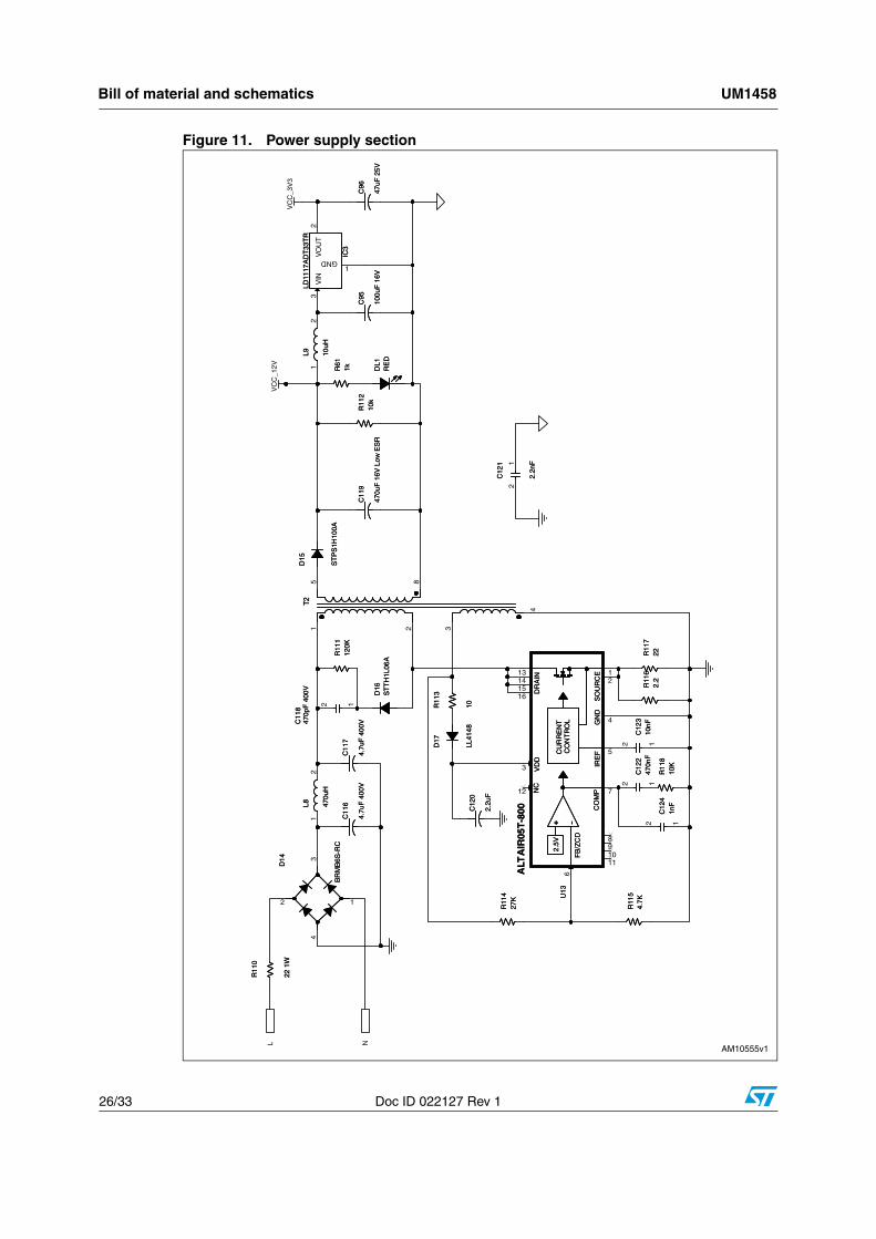
2.4 Power suppliesThe board is powered directly by the mains. It includes an insulated extended range power supply and both 50 Hz and 60 Hz frequencies.
The power supply is based on the Altair05T-800 controller for AC-DC converter. It provides 12 Vdc; the 3.3 Vdc is generated an LD1117AXX33 linear regulator starting from the 12 Vdc.
2.5 Power line communicationThe board allows digital data communication through power line modulation using the ST7540 power line modem. For more details about the modem please refer to the ST7540 datasheet. The ST7540 supports B-FSK modulation up to 4800 bps; it is compliant with CENELEC band A, B, and C, supports preamble and unique word reception synchronization, and has a 500 mArms output current with 12 Vpp single-ended thanks to its integrated amplifier. The modem is coupled with the mains by a coupling transformer. The ST7540 is managed by an SPI and two control lines: the REG_DATA line, which is used to select the access to the configuration register or to the data, and the RxTx line which is used to select the reception or transmission mode. Moreover, the ST7540 provides information about the preamble/unique-word detection (CD/PD) and the carrier sensing (BU) by two digital outputs. Table 1 shows the MCU resources mapping used for ST7540 management.

PLM smartplug demonstration board components UM1458
8/33 Doc ID 022127 Rev 1
2.6 Energy measurementThe energy meter section is based on the STPM01 programmable single-phase energy meter IC. The STPM01 supports 50-60 Hz -IEC62052-11, IEC62053-2X specifications with less than 0.1 % error. For further details please refer to the STPM01 datasheet. The current sensing is done by the current transformer; the STPM01 also measures the mains voltage. The image in Figure 3 shows the wiring diagram in case the user wants to drive and monitor the same AC load. In this case, in fact, it is necessary to power the common contact of the output relay by the phase.
Figure 3. Wiring diagram for monitored and controlled AC load
It is also possible to control a generic load (AC or DC) different from the monitored AC one with the wiring diagram shown in Figure 4.
Table 1. STM32 resources – ST7540 function mapping
STM32 resource ST7540 function
PA1 REG_DATA
PA2 CD/PD
PA3 BU
PA4 RxTx
SPI1-SCK (PA5) SCK
SPI1-MISO (PA6) TXD
SPI1-MOSI (PA7) RXD
UM1458 PLM smartplug demonstration board components
Doc ID 022127 Rev 1 9/33
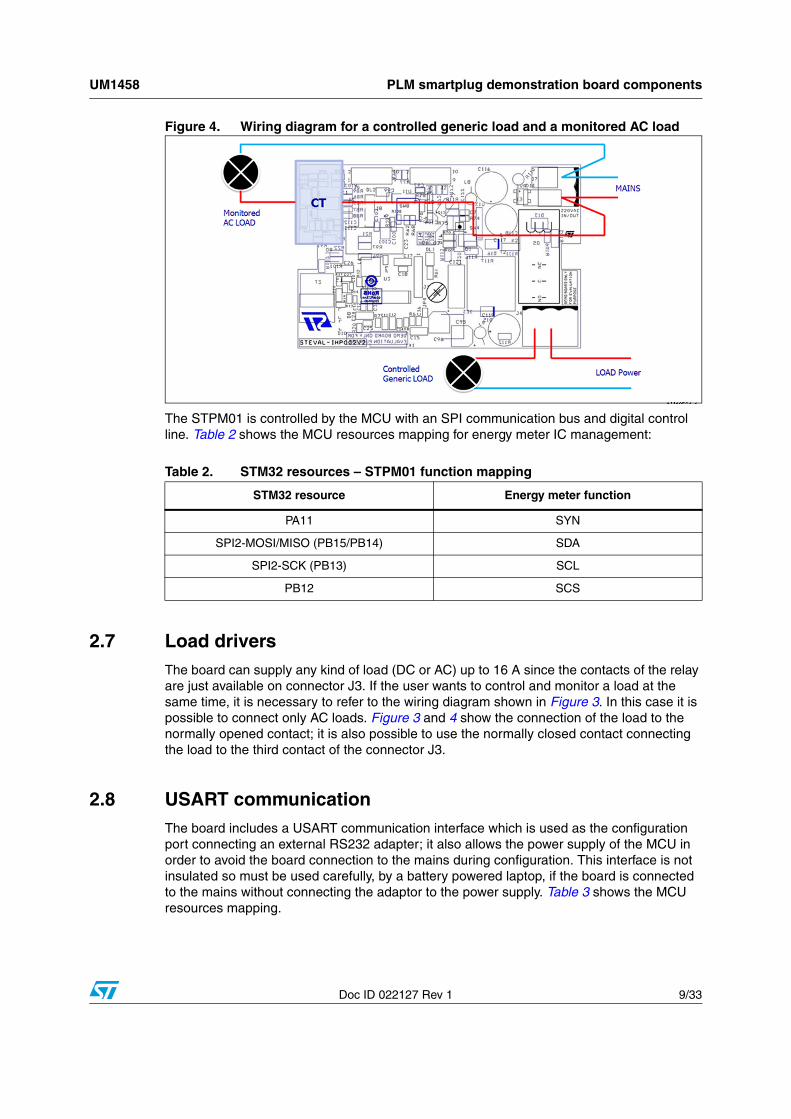
Figure 4. Wiring diagram for a controlled generic load and a monitored AC load
The STPM01 is controlled by the MCU with an SPI communication bus and digital control line. Table 2 shows the MCU resources mapping for energy meter IC management:
2.7 Load driversThe board can supply any kind of load (DC or AC) up to 16 A since the contacts of the relay are just available on connector J3. If the user wants to control and monitor a load at the same time, it is necessary to refer to the wiring diagram shown in Figure 3. In this case it is possible to connect only AC loads. Figure 3 and 4 show the connection of the load to the normally opened contact; it is also possible to use the normally closed contact connecting the load to the third contact of the connector J3.
2.8 USART communicationThe board includes a USART communication interface which is used as the configuration port connecting an external RS232 adapter; it also allows the power supply of the MCU in order to avoid the board connection to the mains during configuration. This interface is not insulated so must be used carefully, by a battery powered laptop, if the board is connected to the mains without connecting the adaptor to the power supply. Table 3 shows the MCU resources mapping.
Table 2. STM32 resources – STPM01 function mapping
STM32 resource Energy meter function
PA11 SYN
SPI2-MOSI/MISO (PB15/PB14) SDA
SPI2-SCK (PB13) SCL
PB12 SCS

PLM smartplug demonstration board components UM1458
10/33 Doc ID 022127 Rev 1
2.9 Status LEDs
2.10 Jumpers
2.10.1 Jumper placement
Figure 5. Jumper placement
Table 3. STM32 resources – RS232 function mapping
STM32 resource Serial communication function
USART1-TX (PA9) RS232-TX
USART1-RX (PA10) RS232-RX
Table 4. LED description
LED Description
DL1 5 V power supply
D1 General purpose bi-color
DL2 Energy measurement
UM1458 PLM smartplug demonstration board components
Doc ID 022127 Rev 1 11/33
2.10.2 Jumper positions
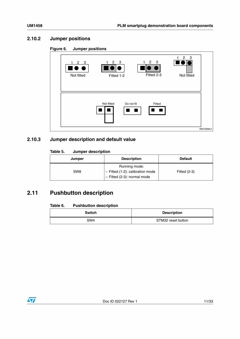
Figure 6. Jumper positions
2.10.3 Jumper description and default value
2.11 Pushbutton description
Table 5. Jumper description
Jumper Description Default
SW8
Running mode:
– Fitted (1-2): calibration mode
– Fitted (2-3): normal mode
Fitted (2-3)
Table 6. Pushbutton description
Switch Description
SW4 STM32 reset button

PLM smartplug demonstration board components UM1458
12/33 Doc ID 022127 Rev 1
2.12 Connector description
Figure 7. Connector position
2.12.1 STM32 JTAG connector
Figure 8. STM32 10-pin JTAG connector
Table 7. Connector description
Connector Description
J2 STM32 JTAG connector
J4 Output relay contacts
J6 STPM01 calibration connector
J7 AC input
UM1458 PLM smartplug demonstration board components
Doc ID 022127 Rev 1 13/33
2.13 Energy meter IC calibration connector
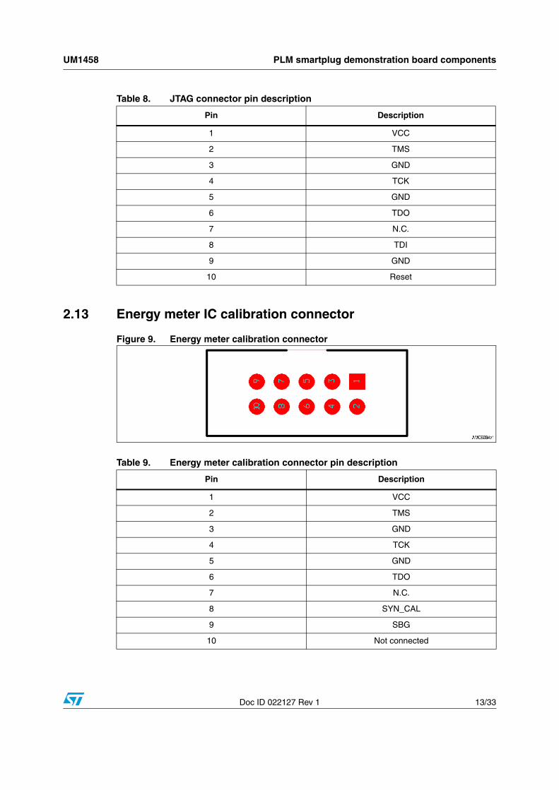
Figure 9. Energy meter calibration connector
Table 8. JTAG connector pin description
Pin Description
1 VCC
2 TMS
3 GND
4 TCK
5 GND
6 TDO
7 N.C.
8 TDI
9 GND
10 Reset
Table 9. Energy meter calibration connector pin description
Pin Description
1 VCC
2 TMS
3 GND
4 TCK
5 GND
6 TDO
7 N.C.
8 SYN_CAL
9 SBG
10 Not connected

Board configuration UM1458
14/33 Doc ID 022127 Rev 1
3 Board configuration
3.1 SPTM01 calibration configurationTo calibrate the STPM01, the SW8 must be set according to Table 5. When this switch is set in calibration mode, the STPM01 can be driven by an external programmer using the J6 connector.
Bill o
f material an
d sch
ematics
UM
1458
15/33D
oc ID 022127 R
ev 1
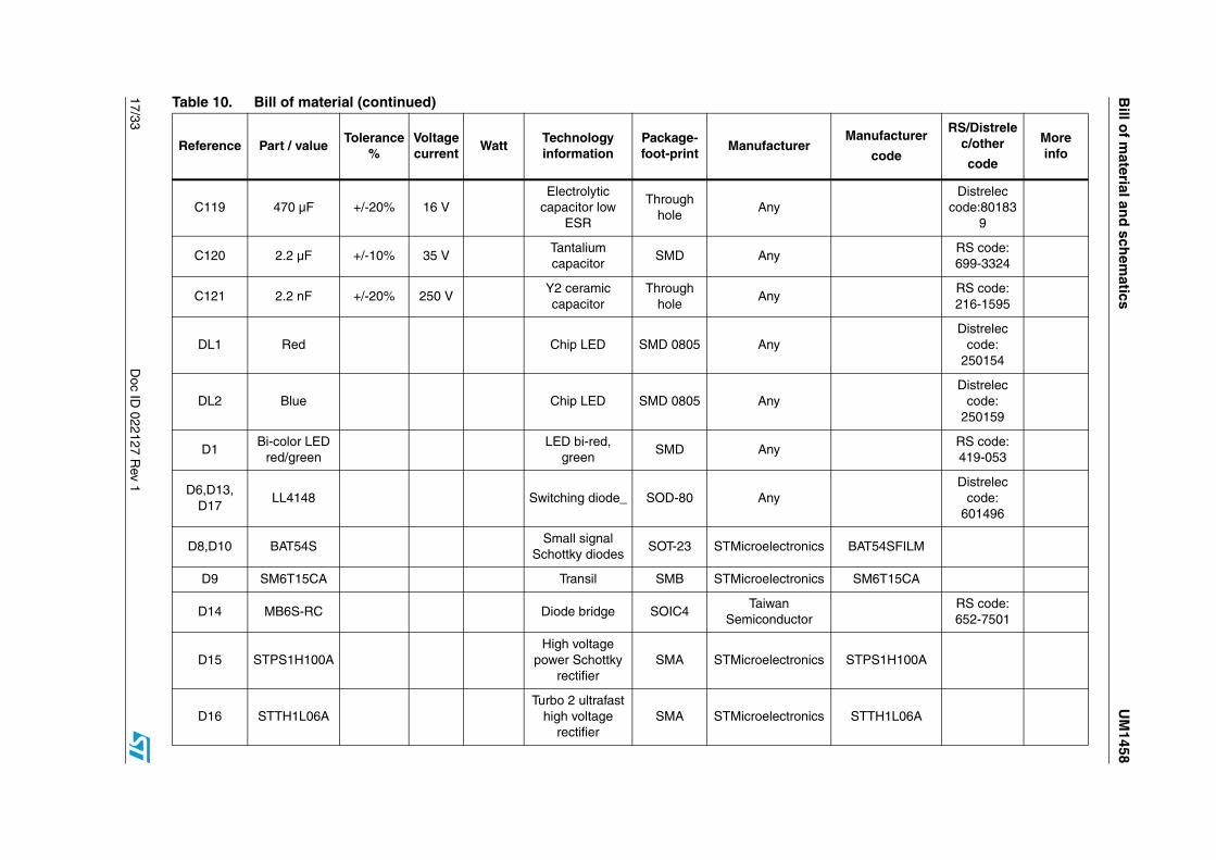
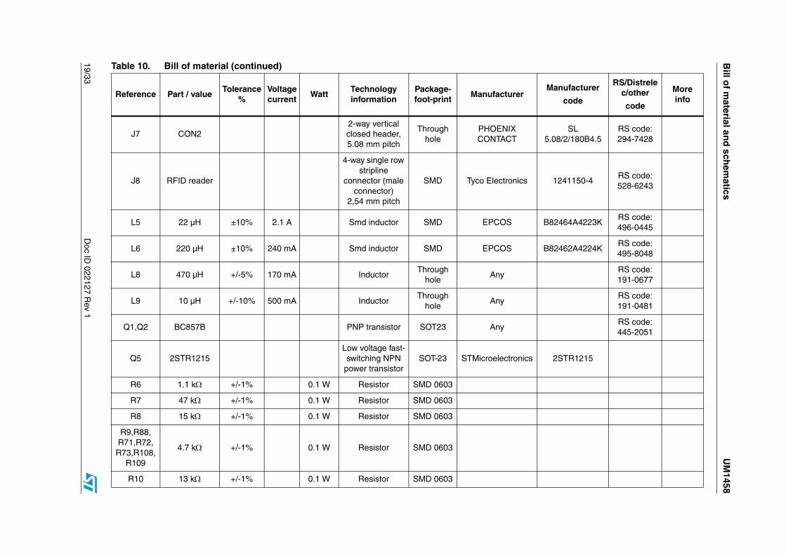
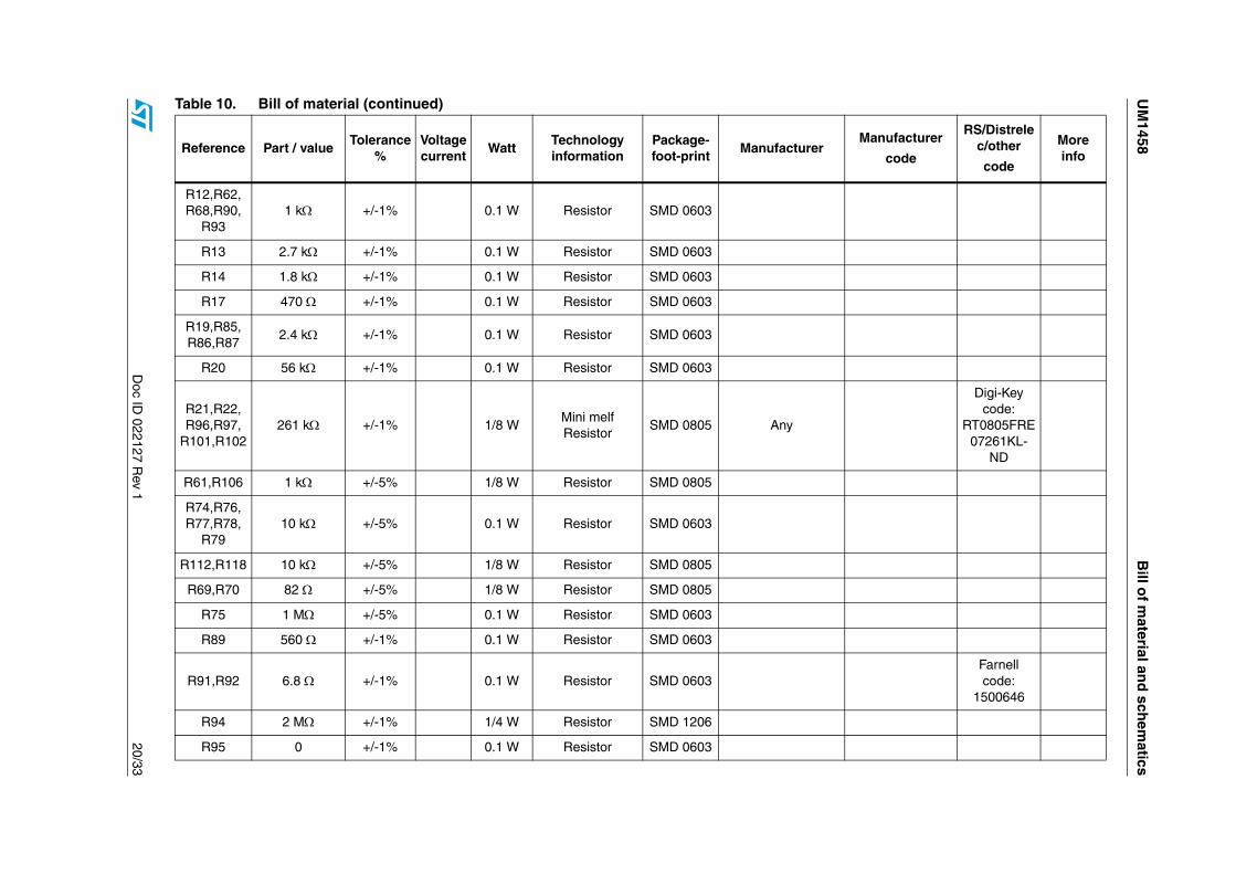
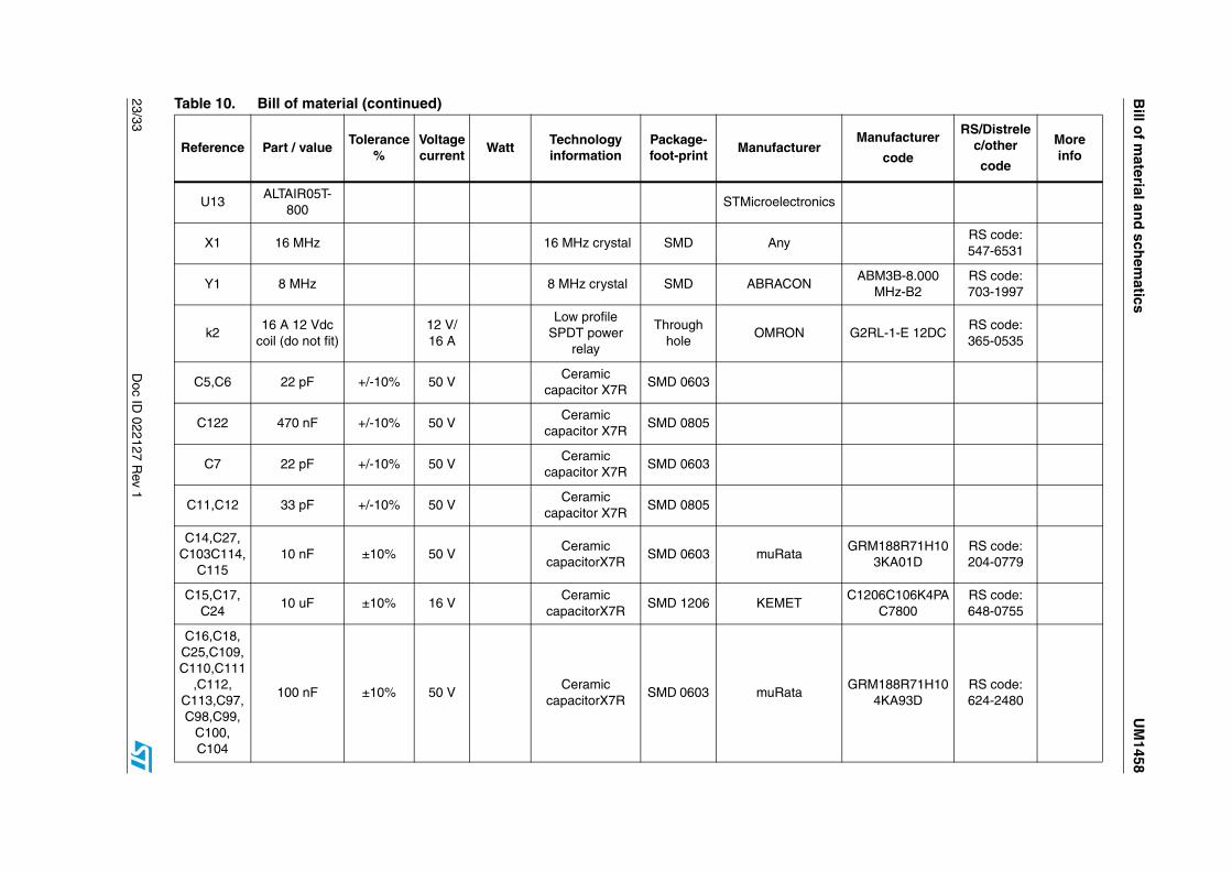
4 Bill of material and schematics
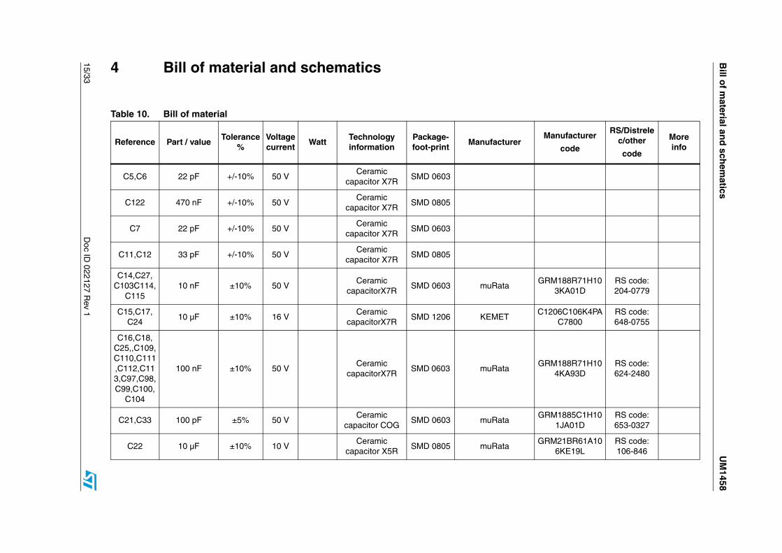
Table 10. Bill of material
Reference Part / valueTolerance
%Voltage current
WattTechnology information
Package-foot-print
ManufacturerManufacturer
code
RS/Distrelec/other
code
More info
C5,C6 22 pF +/-10% 50 VCeramic
capacitor X7RSMD 0603
C122 470 nF +/-10% 50 VCeramic
capacitor X7RSMD 0805
C7 22 pF +/-10% 50 VCeramic
capacitor X7RSMD 0603
C11,C12 33 pF +/-10% 50 VCeramic
capacitor X7RSMD 0805
C14,C27, C103C114,
C11510 nF ±10% 50 V
Ceramic capacitorX7R
SMD 0603 muRataGRM188R71H10
3KA01DRS code: 204-0779
C15,C17, C24
10 µF ±10% 16 VCeramic
capacitorX7RSMD 1206 KEMET
C1206C106K4PAC7800
RS code: 648-0755
C16,C18, C25,,C109,C110,C111,C112,C113,C97,C98,C99,C100,
C104
100 nF ±10% 50 VCeramic
capacitorX7RSMD 0603 muRata
GRM188R71H104KA93D
RS code: 624-2480
C21,C33 100 pF ±5% 50 VCeramic
capacitor COGSMD 0603 muRata
GRM1885C1H101JA01D
RS code: 653-0327
C22 10 µF ±10% 10 VCeramic
capacitor X5RSMD 0805 muRata
GRM21BR61A106KE19L
RS code: 106-846

UM
1458B
ill of m
aterial and
schem
atics
Doc ID
022127 Rev 1
16/33
C23 68 nF ±20% 300 V X2 CapacitorThrough
holeAny
Distrelec code:
821885
C26 6.8 nF ±5% 50 VCeramic
capacitor COGSMD 1206 muRata
GRM3195C1H682JA01D
RS code: 624-2597
C30 15 pF ±5% 50 VCeramic
capacitor COGSMD 0402 muRata
GRM1555C1H150JZ01D
RS code: 624-2935
C31 22 pF ±5% 50 VCeramic
capacitor COGSMD 0402 muRata
GRM1555C1H220JZ01D
RS code: 624-2187
C32 270 pF ±5% 50 VCeramic
capacitor COGSMD 0603 KEMET
C0603C271J5GAC7867
RS code: 147-207
C95 100 µF +/-20% 16 VElectrolytic capacitor
SMD AnyRS code: 565-695
C96 47 µF +/-20% 25 VElectrolytic capacitor
SMD AnyRS code: 565-712
C101 10 µF 10% 10 VTantalium capacitor
SMD AnyRS code: 464-7619
C123 10 nF +/-10% 50 VCeramic
capacitor X7RSMD 0805
C124 1 nF +/-10% 50 VCeramic
capacitor X7RSMD 0805
C108 1 nF +/-10% 50 VCeramic
capacitor X7RSMD 0603
C116,C117 4.7 µF +/-20% 400 VElectrolytic capacitor
Through hole
AnyRS code: 365-4745
C118 470 pF +/-10% 400 VCeramic
capacitor X7RSMD 1206 Any
RS code: 192-718
Table 10. Bill of material (continued)
Reference Part / valueTolerance
%Voltage current
WattTechnology information
Package-foot-print
ManufacturerManufacturer
code
RS/Distrelec/other
code
More info
Bill o
f material an
d sch
ematics
UM
1458
17/33D
oc ID 022127 R
ev 1
C119 470 µF +/-20% 16 VElectrolytic
capacitor low ESR
Through hole
AnyDistrelec
code:801839
C120 2.2 µF +/-10% 35 VTantalium capacitor
SMD AnyRS code: 699-3324
C121 2.2 nF +/-20% 250 VY2 ceramic capacitor
Through hole
AnyRS code: 216-1595
DL1 Red Chip LED SMD 0805 AnyDistrelec
code: 250154
DL2 Blue Chip LED SMD 0805 AnyDistrelec
code: 250159
D1Bi-color LED
red/greenLED bi-red,
greenSMD Any
RS code: 419-053
D6,D13, D17
LL4148 Switching diode_ SOD-80 AnyDistrelec
code: 601496
D8,D10 BAT54SSmall signal
Schottky diodesSOT-23 STMicroelectronics BAT54SFILM
D9 SM6T15CA Transil SMB STMicroelectronics SM6T15CA
D14 MB6S-RC Diode bridge SOIC4Taiwan
SemiconductorRS code: 652-7501
D15 STPS1H100AHigh voltage
power Schottky rectifier
SMA STMicroelectronics STPS1H100A
D16 STTH1L06ATurbo 2 ultrafast
high voltage rectifier
SMA STMicroelectronics STTH1L06A
Table 10. Bill of material (continued)
Reference Part / valueTolerance
%Voltage current
WattTechnology information
Package-foot-print
ManufacturerManufacturer
code
RS/Distrelec/other
code
More info

UM
1458B
ill of m
aterial and
schem
atics
Doc ID
022127 Rev 1
18/33
F1 1 AFuse with clip
1 ASMD Schurter 3404.2416.22
RS code: 703-2742
IC3LD1117ADT3
3TR
Low drop fixed and adjustable positive voltage
regulators
DPAK STMicroelectronicsLD1117ADT33T
R
JP4,JP5 Close Do not fit Do not fit Do not fit Do not fit Do not fit
J1Peak meter connector
5-way single row stripline
connector (male connector)
2,54 mm pitch
Vertical through
hole Any
RS code:495-
8470
J2 JTAG
2x10-way double row stripline
connector (male connector) 2,54
mm pitch
Vertical through
hole Any
RS code: 1732764
J3 USART
3-way single row stripline
connector (male connector)
2,54 mm pitch
SMD Tyco Electronics 1241150-3 RS code: 528-6237
J4 CON33-way vertical closed header, 5.08 mm pitch
Through hole
PHOENIX CONTACT
SL 5.08/3/180BRS code: 294-8443
J6 CAL CON
2x10-way double row stripline
connector (male connector)
2,54mm pitch
Vertical through
hole Any
RS code: 1732764
Table 10. Bill of material (continued)
Reference Part / valueTolerance
%Voltage current
WattTechnology information
Package-foot-print
ManufacturerManufacturer
code
RS/Distrelec/other
code
More info
Bill o
f material an
d sch
ematics
UM
1458
19/33D
oc ID 022127 R
ev 1
J7 CON22-way vertical closed header, 5.08 mm pitch
Through hole
PHOENIX CONTACT
SL 5.08/2/180B4.5
RS code: 294-7428
J8 RFID reader
4-way single row stripline
connector (male connector)
2,54 mm pitch
SMD Tyco Electronics 1241150-4 RS code: 528-6243
L5 22 µH ±10% 2.1 A Smd inductor SMD EPCOS B82464A4223KRS code: 496-0445
L6 220 µH ±10% 240 mA Smd inductor SMD EPCOS B82462A4224KRS code: 495-8048
L8 470 µH +/-5% 170 mA InductorThrough
hole Any
RS code: 191-0677
L9 10 µH +/-10% 500 mA InductorThrough
hole Any
RS code: 191-0481
Q1,Q2 BC857B PNP transistor SOT23 AnyRS code: 445-2051
Q5 2STR1215Low voltage fast-switching NPN
power transistorSOT-23 STMicroelectronics 2STR1215
R6 1.1 kΩ +/-1% 0.1 W Resistor SMD 0603
R7 47 kΩ +/-1% 0.1 W Resistor SMD 0603
R8 15 kΩ +/-1% 0.1 W Resistor SMD 0603
R9,R88, R71,R72,
R73,R108,R109
4.7 kΩ +/-1% 0.1 W Resistor SMD 0603
R10 13 kΩ +/-1% 0.1 W Resistor SMD 0603
Table 10. Bill of material (continued)
Reference Part / valueTolerance
%Voltage current
WattTechnology information
Package-foot-print
ManufacturerManufacturer
code
RS/Distrelec/other
code
More info
UM
1458B
ill of m
aterial and
schem
atics
Doc ID
022127 Rev 1
20/33
R12,R62, R68,R90,
R931 kΩ +/-1% 0.1 W Resistor SMD 0603
R13 2.7 kΩ +/-1% 0.1 W Resistor SMD 0603
R14 1.8 kΩ +/-1% 0.1 W Resistor SMD 0603
R17 470 Ω +/-1% 0.1 W Resistor SMD 0603
R19,R85, R86,R87
2.4 kΩ +/-1% 0.1 W Resistor SMD 0603
R20 56 kΩ +/-1% 0.1 W Resistor SMD 0603
R21,R22, R96,R97,
R101,R102261 kΩ +/-1% 1/8 W
Mini melf Resistor
SMD 0805 Any
Digi-Key code:
RT0805FRE07261KL-
ND
R61,R106 1 kΩ +/-5% 1/8 W Resistor SMD 0805
R74,R76, R77,R78,
R7910 kΩ +/-5% 0.1 W Resistor SMD 0603
R112,R118 10 kΩ +/-5% 1/8 W Resistor SMD 0805
R69,R70 82 Ω +/-5% 1/8 W Resistor SMD 0805
R75 1 MΩ +/-5% 0.1 W Resistor SMD 0603
R89 560 Ω +/-1% 0.1 W Resistor SMD 0603
R91,R92 6.8 Ω +/-1% 0.1 W Resistor SMD 0603Farnell code:
1500646
R94 2 MΩ +/-1% 1/4 W Resistor SMD 1206
R95 0 +/-1% 0.1 W Resistor SMD 0603
Table 10. Bill of material (continued)
Reference Part / valueTolerance
%Voltage current
WattTechnology information
Package-foot-print
ManufacturerManufacturer
code
RS/Distrelec/other
code
More info

Bill o
f material an
d sch
ematics
UM
1458
21/33D
oc ID 022127 R
ev 1
R98,R103 475 Ω +/-1% 1/8 W Mini melf resistor SMD 0805 Any
Digi-Key code:
RT0805FRE07475RL
R99 43 kΩ +/-1% 0.1 W Resistor SMD 0603
R100 100 Ω +/-1% 0.1 W Resistor SMD 0603
R1051 kΩ (do not
fit)+/-1% 1/4 W Resistor SMD 1206
R110 22 Ω +/-5% 1 W Fuse resistorThrough
hole Any
RS code: 214-0920
R111 120 kΩ +/-5% 1/4 W Resistor SMD 1206
R113 10 Ω +/-5% 1/8 W Resistor SMD 0805
R114 27 kΩ +/-1% 1/8 W Resistor SMD 0805
R115 4.7 kΩ +/-1% 1/8 W Resistor SMD 0805
R116 2.2 Ω +/-1% 1/8 W Resistor SMD 0805
R117 22 Ω +/-1% 1/8 W Resistor SMD 0805
RV1 VAR275V 275 V SMD varistor SMD EPCOS B72650M271K72Distrelec
code: 730096
SW4 RstSurface mount tactile switch
SMD C & K Y78B22110FPRS code 505-9186
SW8Calibration
settings
3-way single row stripline
connector (male connector) 2,54
mm pitch
SMD Tyco Electronics 1241150-3 RS code: 528-6237
Single stripline 3
poli
Table 10. Bill of material (continued)
Reference Part / valueTolerance
%Voltage current
WattTechnology information
Package-foot-print
ManufacturerManufacturer
code
RS/Distrelec/other
code
More info

UM
1458B
ill of m
aterial and
schem
atics
Doc ID
022127 Rev 1
22/33
TP8,TP9, TP10,TP11
,TP12, TP13,
TP14,TP15,TP16, TP17, TP18, TP19, TP20, TP21, TP22, TP23, TP25,
TP26,TP27
Test point Test point Test point Test point Test point Test point
T1Current
transformerCurrent
transformerThrough
hole VAC
T60404-E 4622-X503
T2Custom
transformerCustom
transformerThrough
hole MAGNETICA 1921.0013 rev.2
T3Line
transformerLine transformer SMD VAC
T60403-K5024-X044
U3 ST7540FSK power line
transceiverHTSSOP2
8STMicroelectronics ST7540TR
U11STM32F103C
BT6
Medium-density performance line ARM-based 32-
bit MCU
LQFP48 STMicroelectronicsSTM32F103CBT
6
U12 STPM01
Programmable single phase
energy metering IC with tamper
detection
TSSOP20 STMicroelectronics STPM01FTR
Table 10. Bill of material (continued)
Reference Part / valueTolerance
%Voltage current
WattTechnology information
Package-foot-print
ManufacturerManufacturer
code
RS/Distrelec/other
code
More info
Bill o
f material an
d sch
ematics
UM
1458
23/33D
oc ID 022127 R
ev 1
U13ALTAIR05T-
800STMicroelectronics
X1 16 MHz 16 MHz crystal SMD AnyRS code: 547-6531
Y1 8 MHz 8 MHz crystal SMD ABRACONABM3B-8.000
MHz-B2 RS code: 703-1997
k216 A 12 Vdc
coil (do not fit)12 V/ 16 A
Low profile SPDT power
relay
Through hole
OMRON G2RL-1-E 12DCRS code: 365-0535
C5,C6 22 pF +/-10% 50 VCeramic
capacitor X7RSMD 0603
C122 470 nF +/-10% 50 VCeramic
capacitor X7RSMD 0805
C7 22 pF +/-10% 50 VCeramic
capacitor X7RSMD 0603
C11,C12 33 pF +/-10% 50 VCeramic
capacitor X7RSMD 0805
C14,C27, C103C114,
C11510 nF ±10% 50 V
Ceramic capacitorX7R
SMD 0603 muRataGRM188R71H10
3KA01DRS code: 204-0779
C15,C17, C24
10 uF ±10% 16 VCeramic
capacitorX7RSMD 1206 KEMET
C1206C106K4PAC7800
RS code: 648-0755
C16,C18, C25,C109,C110,C111
,C112, C113,C97,C98,C99,
C100, C104
100 nF ±10% 50 VCeramic
capacitorX7RSMD 0603 muRata
GRM188R71H104KA93D
RS code: 624-2480
Table 10. Bill of material (continued)
Reference Part / valueTolerance
%Voltage current
WattTechnology information
Package-foot-print
ManufacturerManufacturer
code
RS/Distrelec/other
code
More info

UM
1458B
ill of m
aterial and
schem
atics
Doc ID
022127 Rev 1
24/33
C21,C33 100 pF ±5% 50 VCeramic
capacitor COGSMD 0603 muRata
GRM1885C1H101JA01D
RS code: 653-0327
C22 10 µF ±10% 10 VCeramic
capacitor X5RSMD 0805 muRata
GRM21BR61A106KE19L
RS code: 106-846
C23 68 nF ±20% 300 V X2 capacitorThrough
holeAny
Distrelec code:
821885
C26 6.8 nF ±5% 50 VCeramic
capacitor COGSMD 1206 muRata
GRM3195C1H682JA01D
RS code: 624-2597
C30 15 pF ±5% 50 VCeramic
capacitor COGSMD 0402 muRata
GRM1555C1H150JZ01D
RS code: 624-2935
C31 22 pF ±5% 50 VCeramic
capacitor COGSMD 0402 muRata
GRM1555C1H220JZ01D
RS code: 624-2187
C32 270 pF ±5% 50 VCeramic
capacitor COGSMD 0603 KEMET
C0603C271J5GAC7867
RS code: 147-207
C95 100 µF +/-20% 16 VElectrolytic capacitor
SMD AnyRS code: 565-695
J7a CON3
2-way cable mount screw
terminal, 5.08 mm
Through hole
Phoenix Contact BL 5.08/2RS code: 403-875
Not mounted on PCB
Table 10. Bill of material (continued)
Reference Part / valueTolerance
%Voltage current
WattTechnology information
Package-foot-print
ManufacturerManufacturer
code
RS/Distrelec/other
code
More info

UM1458 Bill of material and schematics
Doc ID 022127 Rev 1 25/33
Figure 10. Top page
Bill of material and schematics UM1458
26/33 Doc ID 022127 Rev 1
Figure 11. Power supply section

UM1458 Bill of material and schematics
Doc ID 022127 Rev 1 27/33
Figure 12. USART expansion connector section

Bill of material and schematics UM1458
28/33 Doc ID 022127 Rev 1
Figure 13. Power line modem section

UM1458 Bill of material and schematics
Doc ID 022127 Rev 1 29/33
Figure 14. MCU section

Bill of material and schematics UM1458
30/33 Doc ID 022127 Rev 1
Figure 15. STPM01

UM1458 Bill of material and schematics
Doc ID 022127 Rev 1 31/33
Figure 16. Output drivers

Revision history UM1458
32/33 Doc ID 022127 Rev 1
5 Revision history
Table 11. Document revision history
Date Revision Changes
09-Nov-2011 1 Initial release.
UM1458
Doc ID 022127 Rev 1 33/33
Please Read Carefully:
Information in this document is provided solely in connection with ST products. STMicroelectronics NV and its subsidiaries (“ST”) reserve theright to make changes, corrections, modifications or improvements, to this document, and the products and services described herein at anytime, without notice.
All ST products are sold pursuant to ST’s terms and conditions of sale.
Purchasers are solely responsible for the choice, selection and use of the ST products and services described herein, and ST assumes noliability whatsoever relating to the choice, selection or use of the ST products and services described herein.
No license, express or implied, by estoppel or otherwise, to any intellectual property rights is granted under this document. If any part of thisdocument refers to any third party products or services it shall not be deemed a license grant by ST for the use of such third party productsor services, or any intellectual property contained therein or considered as a warranty covering the use in any manner whatsoever of suchthird party products or services or any intellectual property contained therein.
UNLESS OTHERWISE SET FORTH IN ST’S TERMS AND CONDITIONS OF SALE ST DISCLAIMS ANY EXPRESS OR IMPLIEDWARRANTY WITH RESPECT TO THE USE AND/OR SALE OF ST PRODUCTS INCLUDING WITHOUT LIMITATION IMPLIEDWARRANTIES OF MERCHANTABILITY, FITNESS FOR A PARTICULAR PURPOSE (AND THEIR EQUIVALENTS UNDER THE LAWSOF ANY JURISDICTION), OR INFRINGEMENT OF ANY PATENT, COPYRIGHT OR OTHER INTELLECTUAL PROPERTY RIGHT.
UNLESS EXPRESSLY APPROVED IN WRITING BY TWO AUTHORIZED ST REPRESENTATIVES, ST PRODUCTS ARE NOTRECOMMENDED, AUTHORIZED OR WARRANTED FOR USE IN MILITARY, AIR CRAFT, SPACE, LIFE SAVING, OR LIFE SUSTAININGAPPLICATIONS, NOR IN PRODUCTS OR SYSTEMS WHERE FAILURE OR MALFUNCTION MAY RESULT IN PERSONAL INJURY,DEATH, OR SEVERE PROPERTY OR ENVIRONMENTAL DAMAGE. ST PRODUCTS WHICH ARE NOT SPECIFIED AS "AUTOMOTIVEGRADE" MAY ONLY BE USED IN AUTOMOTIVE APPLICATIONS AT USER’S OWN RISK.
Resale of ST products with provisions different from the statements and/or technical features set forth in this document shall immediately voidany warranty granted by ST for the ST product or service described herein and shall not create or extend in any manner whatsoever, anyliability of ST.
ST and the ST logo are trademarks or registered trademarks of ST in various countries.
Information in this document supersedes and replaces all information previously supplied.
The ST logo is a registered trademark of STMicroelectronics. All other names are the property of their respective owners.
© 2011 STMicroelectronics - All rights reserved
STMicroelectronics group of companies
Australia - Belgium - Brazil - Canada - China - Czech Republic - Finland - France - Germany - Hong Kong - India - Israel - Italy - Japan - Malaysia - Malta - Morocco - Philippines - Singapore - Spain - Sweden - Switzerland - United Kingdom - United States of America
www.st.com