
UM 80 7 18 0153 - DTIC
51
UJS4VRADCOM-TM-M0D-7 "ADA086857 INVESTIGATION OF HELICOPTER WIRE STRIKE PROTECTION CONCEPTS LI-E LeRoy T. Bu.rrowsiLEVE June 1980 DTIC ELECTE S JUL 2 1 1980 *ý A B Approved for public release; distribution unlimited. APPLIED TECHNOLOGY LABORATORY U. S. ARMY RESEARCH AND TECHNOLOGY LABORATORIES (AVRADCOM) Fort Eustis, Va. 23604 UM 80 7 18 0153 /. -. , ., ,. ;, .]p-
Transcript of UM 80 7 18 0153 - DTIC

UJS4VRADCOM-TM-M0D-7
"ADA086857
INVESTIGATION OF HELICOPTER WIRE STRIKEPROTECTION CONCEPTS
LI-E
LeRoy T. Bu.rrowsiLEVE
June 1980
DTICELECTES JUL 2 1 1980
*ý AB
Approved for public release;distribution unlimited.
APPLIED TECHNOLOGY LABORATORY
U. S. ARMY RESEARCH AND TECHNOLOGY LABORATORIES (AVRADCOM)
Fort Eustis, Va. 23604
UM
80 7 18 0153
/.
-. , ., ,. ;, .]p-
Th. findings in this report are not to be construed as an official Department of the Army position unless sodesignated by other authorized jocumenti.I When Gjovernment drawiangs, specifications, or other data are used for any purpoee other than In connectionwith a definitely related Governmeolnt procurement operation, the United States Governmewnt thereby incurs noresponsibility nor any obligation whatsoever; and the fact that the Governmewnt troy hsve formulated, furnished.or In any way supp~lied the said dr~wings. specifications, or other data Is not to be regarded by implication orotherwise as in any manner licensing the holder or any other person or corporation, or conveying any rights orpermission, to manufacture, uae, or aell any patented invention that may in any way be related thereto.Trade n~anwa cited In this report do not constitute an official esidorsemnent or approval of the use of suchtI
DISPOSITION INSTRUCTIONS
Destroy this report when no longer noeded. Do not return it to the originator.
J~kf
0I

SECURITY CLASSIFICATION OFTHIIS PAGE ýVlhamnor nf)., *Iedj
REPORT DOCUMENTATION PAGE READ INSTRUCTIONSBEFORE COMPLETING FORM
:F-DAT ~ ~ G5 2 OVT ACCESSION NO- 3, RECIPIENT'S CATALOG NUMBER
USAAVFIAOC6M.TM-8 *D-7 Ah-, 6 __771j - P 041. 6 PERIOD COVERED
'~ ~ W dS~ 4 ~,~ E ~ 2 Technical tem o-
\. PROTECTION CONCEPTS Auj l .ojf ,,07.g-51P
7.AUTtIQR.4&) 6. CONTRACT OR GRANT NUMBER(a)
Leo T urrows, House Task 79-16
9. PERFORMING ORGANIZATION NAME ANO ADDRESS 10. PROGRAM ELEMENT, PROJECT. TASK
Applied Technology Laboratory, U. S. Army Research and _RA.
Technology Laboratories (AVRADCOM) 1L126 H7Fort Fustis, Vil~ini3 23604 1 '_ _ _ _ _
11 CONTROLLING OFFICE NAME AND ADDRESS
14, MONITORING AGENCY NAME a ADORESS(f diII.,,Ii Irotn Coni~oiIIg GfIc.) 15. SECURITT CLASS. (of [Mt.* report)
I Unclassified/ - IS OrCLASIFIICATION; OWNGRADING
16 DISTRIBUITION STATEMENT (,( thie ReporIt)SH D L
Approved for public release: distribution inlimited.
17. OISTRIBI&TiON STA"EIIENT (of Ith. .SIcI .,.d In Block 20, It diff.ern Ityo Roporg'
IS. SUPPLEMENTARY NOTES
ILý KEY WO0R05 (COllin onlU floe JoV e 1i .Id*clf*k*fr ad Identity by Stock nomb~r)
Helicopters Protective Equipment Impact TestsCable Cuttit'g Dev~c-s Retrofitting Test Medt'ocicCdbles Aviation Accidents
VV'rpAviation SafetyCutters Low Altitude
2( A&STRAL.. 1`7-- -. vv-I oldff If -.0,, - Id-ft,I b;, SIOCS v..b.o)
In-flight wiIC strikcs pose a serious threat to low-level helicopter onerations, Tests were con-Pr~tu~Con Systemn [WSPS), developed by Bristol Aerospace Limited. The WSPS co.-s;sts of
f uselage mounted uppet and lowver cutters and a wil.ishield centerpost deflector w,,h a sawtooth
Do, F OR" 14 EDITION (IF 14VIS 085 OEEn~Sd"
,EC.UQF' YLLA55IF-IATION OF THIS PAGE 'SI O).(. i.,- -o

S ~ Unclassified
69CURITY CLASSIFICATION OF TIS PAGQ[r'I., DflI. Lrf.f.d)
I - Block 20. Abstract - continued.
Using the NASA/Langley Research Center Crash Impact Dynamics Facility, an OH-58A fittedwith the WSPS was subjected to pendulum swing tests in which the helicopter struck fixedcables at approximately 40 knots airspeed. The system demonstrated the capability to easilysever 10,000-pound-strength 3/8-inch steel messenger cable, 50-pair copper communicationscable, and 0.419-inch high-power transmission lines, including multiple arrays of those cables.Data acquired indicated that the wire impact/deflection/cutting sequence would not have a •significant effect on helicopter performance, control, crew functioning, or blade flapping. In-stallation of the WSPS on tve entire Army tactical helicopter fleet is recommended.
An additional test of a device to deflect wires past the helicopter skid gear, vertica! stabilizer,and tail rotor was conducted. A 7/8-inch tubular steel deflector was designed and fabricated.The device proved to be inadequate. It wvas concluded that a skid gear deflector is not apractical OH 58A retrofit from 3 cost and weight standpoint.
II
Unclassi 'ed
Ii
P',

P RE FACEj
The project engineer for the tests described herein was LeRoy T. Burrows, Aerospace
1.
Engineer, Safety and Survivability Technical Area, Aeronautical Systems Division, AppliedTechnology Laboratory (ATL). Other contributing ATL personnel were Mr. Paul Triplett,lead Aerospace Technic!,.i,; Mr. John Chappell, Instrumentation Engineer; and Mr. Dominiclanuzzi, Instrumentation Technician.
The author extends his gratitude to the following organizations and individuals for thesupport specified:
* NASA-Langley Research Center (LRC) for facility support, conducting the pendulum pswings of the aircraft, and external photography. Dr. Robert Thomson, Mr. Claude
& Castle, and Mr. Dwight McSmith, all of the LRC, were instrumental in the successof these tests.
* U. S. Army Transportation School, Department of Aviation Systems, for loan ofthe test vehicle and for conducting the weight and balance measurement of thisaircraft.
* U, S. Army Transportation Center and Fort Eustis Directorate of FacilitiesEngineering, Utilities Division, Electrical Branch, and the U. S. Army Communica-tiofns Command Detachment, Fort Eustis, for erecting the wires for these tests-
* ATL. Technical Services Division for test preparation; principally Messrs. Edwards,Krowe, and Doxey.
ACCESSION for
NTIS Wnite Section NODOC Buff Section 0UNNNeU-rF0 13JUStIrICAHON I
3 18Y0
IiL , - .,--4'.

L
TABLE OF CONTENTS
Page
PREFACE ................................................................................................................. 3
LIST OF ILLUSTRATIONS ......................................... 5
LIST OF TABLES ........................................................... 8
INTRODUCTION ..................................................................................................... 9
TEST PROG RAM ..................................................................................................... 11
W ire Strike Protection System Experim ent .................................................... 11
Skid Gear W ire Deflector Experiment ........................................................... 11
TEST FACILITY ...................................................................................................... 12
TEST SETUP ............................................................................................................ 15
Aircraft and Cutter/Deflector Systems ............................................................ 15
Obiective W ire ................................................................................................... 19
Instrumentation .................................................................................................. 22
Photographic Coverage .................................................................................... 23
TEST DESCRIPTION ................................................................................................ 25
TEST RESULTS ........................................................................................................ 28
W ire Strike Protection System Experim ent .................................................... 28
Skid Gear W ire Deflector Experiment .......................................................... 41
CONCLUSIONS .......................................................................................................... 45
RECOM M ENDATIONS ............................................................................................. 46
APPENDIX A - INSTRUM ENTATION ................................................................. 47
5
€ o
,• • • ,--_,•- .o- .. .. _- _• ,,....• .,•- . . . ............

LIST OF ILLUSTRATIONS
Figure Page
1 Langley Crash Impact Dynamics Research Facility ............................ 13
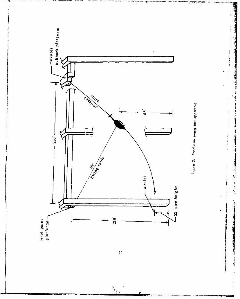
2 Pendulum swing test apparatus ............................................................ 14
3 WSPS upper cutter ............................................................................... 16
4 WSPS lower cutter ................................................................................ 17
5 WSPS windshield centerpost deflector ........................... 18
6 Skid gear deflector, side view ............................................................. 20
7 Skid gear deflector, front view ........................................................... 204
8 Tail deflector system ......................................... 21
9 Pullback cable attachment fixture ........................................................ 21
10 Canadian wire cutting test apparatus .................................................. 22
11 Test instrumemtation and battery installation ...................................... 23
12 Cockpit camera installation .................................................................. 24
13 Ckid gear camera installation ................................................................ 24
14 Pre-pullback position ........................................................................... 25
15 Pullback positio n ................................................................................. 26
16 Objective wire and communications cable after being severed .......... 28
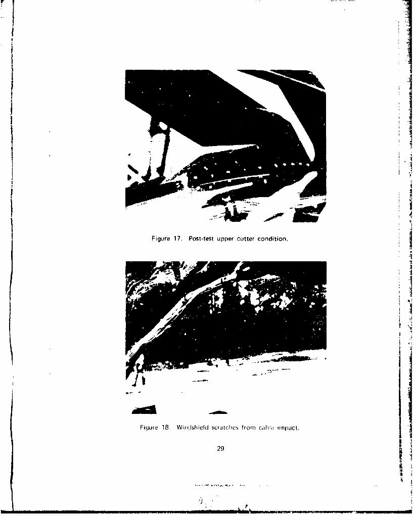
17 Post-test upper cutter condition ..................................... .......... 29
18 Windshield scratches from cable impact .............................................. 29
19 Test 4 longitudinal impact fnrces ........................................................ 30
20 Test 4 lateral impact forces ................................................................ 31
21 Test 4 pitch attitude change ................................................................ 31
22 Test 5 wire impact damage to aircraft ............................................. 32A
6
-- ____ -.- t.-
LE Pa.e
23 Side view of lower cutter performance ............................................ 33
24 Front view of lower cutter performance................................... 3425 Test 5 pitch attitude change ............................................................... 35
26 Test 5 longitudinal impact forces ....................................................... 35
27 Test 5 lateral impact forces ................................................................ 36
28 Description of multiple cables for Test 7 .......................................... 37
29 Test 7 multiple wires as erected .......................................................... 37
30 Multiple wire test sequence ....................................... 38
31 Test 7 longitudinal impact forces ........................................................ 39
32 Test 7 lateral impact forces ............................................................... 39
33 Test 7 pitch attitude change ............................................................... 40
34 Wire impact sequence during test ........................................................ 42
35 Left line pole after test ...................................................................... 43
36 Right line pole after test .................................................................... 43
37 Post-test concdition of skid gear deflector .......................................... 44
38 Test 6 longitudinal impact forces ........................................................ 44
A-1 Recording system block diagram ................-......................................... 48
A-2 Data playback system block diagram ............................................... 51
7I*11. -

• I LIST OF TABLES
Table Page__
1 A;rcraft conditions at wire im pact ................................................... 26
2 Pendulum sw ing test schedule ............................................................ 27
A -1 Recorder functions ............................................................................. 50
t8
L LI
i.I
t IIJ
I1
8i
I1

INTRODUCTION
In-flight wire strikes are a serious threat during all-weather daytime and nighttime heli-copter operations, including:
0 Terrain flight (nap-of-the-earth, low-level, and contour flight)
* Enclosed area takeoff and landing
0 Confined area maneuver
The U. S. Army's growing emphasis on these operations is a major reason for the recentincrease in wire strikes experienced. Despite concentrated training on avoiding wire •strikes and actions such as mapping of wires in training areas, removal of unnecessarywires, marking of cables with orange spheres or other devices, and preparation of SOP'sto increase pilot awareness of the wire strike threat, the peacetime wire strike problemremains a serious one. During the period 1 January 1974 to 1 January 1980, wirestrikes accounted for 8 percent of total Army aircraft damage, 6 percent of all Armyaircraft injuries, and 16 percent of Army aviation fatalities. Inasmuch as many of thesemishaps have occurred during training over familiar sites, it can be assumed that thewire impact threat posed by combat operations in unfamiliar areas would result inincreased wire strikes. Furthermore, in a hostile environment th., enemy can be expectedto string wires -,s an intrusion countermeasure. ISince the emphasized operations require flight close to the ground during varying degreesof visibility, the hazards presented by wires and other obstacles cannot be eliminated. JHowever, these hazards can be effectively reduced by configuring the helicopt'r systemto be more tolerant of them. Increasing helicopter survivability to the wire strike threat -.will result in fewer mishaps, and therefore, increased aircraft availability, decreased main-tenance, reduced casualties, and improved mission effectiveness.
A simple, cost-effective design approach to providing protection from the wire strikethreat is a helicopter Wire Stri!ve Protection System (WSPS) designed by Bristol Aero-space Limited (BAL) under contract to the Canadian National Defence Headquarters.This system consists of an upper cutter, a lower cutter, and a windshield centerpost de-flector. An examination of electric power and telephone lines in use revealed that asteel, 3/8 inch diameter, seven-strand messenger ciLAe with a tensi;e strength in excess of10,000 pounds was the toughest cable feund in abundance. It is designated as 1OM
cable by the industry. This type of cable had been the cause of many fatal helicopteraccidents. Accordingly, the WSPS was designed to counter the threat of this cable,which was designated the design objective wire. The objective wire is used to support
heavy communications cables that consist of many copper wires within, or to provideother structural support.
In May 1979, the Canadian WSPS was qualified for Canadian KIOWA helicopter (OH-58A)application. BAL conducted a series of 52 wire-cutting tests by mounting a deflector andupper cutter on a wrecked KIOWA fuselage, rigidly securing this to the flatbed of a truck,and driving the truck into fixed wires. Test variables included speed (15 to 60 mph),
9+
'r1-i
-'oI ,I
- + • " ____ - ." .-- --' II I" I • '\• • '" • • r
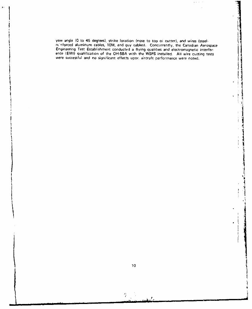
yaw angle (0 to 45 degrees), strike location (nose to top oi cutter), and wires (steel-Sr~iforced aluminum cables, 10M, and guy cables). Concurrently, the Canadian Aerospace
"Engineering Test Establishment conducted a flying qualities and electromagnetic interfer-ence (EMI) qualification of the OH-58A with the WSPS installed. All wire cutting testswere successful and no significant effects upor. aircraft performance were noted.
ii
11i~1
101
I
/ *1'*

* I
TEST PROGRAMI
The wire cutting test method employed by BAL validated upper cutter and deflector
design objectives but did not test the lower cutter. The test also did not answer ques-
tions regarding aircraft pitch and yaw changes and deceleration loads during the wireI impact and cutting sequence, and their potential effects upon aircraft control and blade
flapping. To answer these questions, and thereby determine suitability of a WSPS forArmy aircraft application, was the primary objective of the following ATL tests.
WIRE STRIKE PROTECTION SYSTEM EXPERIMENT
The primary purpose of this experiment was to determine the suitability of the CanadianWSPS for application to U. S. Army helicopters. This was to be accomplished by assess-ing the effect of single and multiple wire impact forces and the deflection/cuttingsequence on aircraft control, the pilot, and blade flapping. In addition, the lower cutterwas to be tested for struc:tural integrity ann wire-cutting capability. The upper cutterand deflector performance and structural integrity had been pro','•n in tests cciducted inCanada by Bristol Aerospace Limited- 1SKID GEAR WIRE DEFLECTOR EXPERIMENT
The purpose of this experiment was to design, fabricate. and test a device that woulddeflect wires an.d caoles past the skid gear, vertical stabilizer, and tail rotor, thereby pro-tecting the helicopter from skid gear wire eFrtanqlerfient for all aircraft wire strike attitudes.With the WSPS it is possihle for the wire to go under the lower cutter and be snagged by
the skid gear, especially in the case of a nose-up attitude.
These tests were conducted in October 1979 at the NASA/Linqley Research CenterCrash Impact Dvnamic.b Facility, Hampton, Virginia. The test veehicle was an Army OH-58A
:,bservation helicopter.
This r port documents test pre )araiion, description, results, arid conclusions.
11 1
; •II I= I Ir [1 "1I' fl TE1 TI-'t -FTT-I' II1•! I II

TEST FACILITY
The OH-58A Wire Strike Protection System test was performed at the Crash ImpactDynamics Research Facility shown in Figure 1. The basic structure of the facility is the420-foot-high by 400 foot-long gantry. It is supported by three sets of inclined legsspread 267 feet apart at the ground level and 67 feet apart at the 218-foot level. Amovable bridge spans the gantry at the 218-foot level and traverses the length of thegantry. A control room and an observation room are located in the building at the base
of the gantry. Along thp centerline of the gantry, ant ground level, is a strip of rein-forced concrete 400 feet long, 30 feet wide, and 0.67 foot thick.
The apparatus necessary to conduct a helicopter pendulum swing test is shown in Figure2. Swingqcable pivot-point platforms, located at the west end of the gantry, supportedthe winche. , sheaves, and puliev systems that controlled the length of the swing cables. Apullback p:Atform, attached to the underside of the movable carriage, supported the winch,sheave, and pulley sysvn that controlled the lenqth of the pullback cable. Swing cab!eswere attached to the helicopter rotor hub and, during the pendulum swing, supported thehelicopter through the rotor mast, as ii would he in free flight. A pullback cable withan el ctrically operated hook was attached to a specially fabricated fixture placed on theaft end o' the tail boom.
Both swing and pullback cables could be varied in length to povide desired pendulumswing arc and velocity. For a wire heiqht of 22 feet. the pullback position shown inFigure 2 was calculated to provide le ds.sired wire impact velocity.
IJ
121

FLI'I �
IiIiI
I �IiI �
lvi U
U
2'I I
iiC-,
C-,
I C
� I
I I U-
13
IJ
00.4Q.
C.L
A%
*1-
N O
j
0. \. -
4- 1
. ii

TEST SETUP
AIRCRAFT AND CUTTE R/DEF LECTOR SYSTEMS
The test specimen was an OH-58A helicopter that had been retired from service and wasbeing used for maintenance training by the U. S. Army Transportation School. It was Ifully equipped less avionic equipment. The aircraft was initially prepared for testing atthe Applied Technology Laboratory. This preparation included installation of the Canadi-an OH-58A Helicopter Wire Strike Protection System and pruvisions for rapid installationof the skid gear deflector concept to be tested.
The Canadian WSPS is shown installed on the test aircraft in Figures 3, 4, and 5. Thisis a cutter/deflector system with an upper cutter to protect the main rotor controls; alower cutter to protect the skid gear; and a windscreen centerpost deflector with a ser-
rated cutting edge insert to deflect wires to the upper cutter, to cut copper and aluminumwires, and to reinforce the centerpost structure. The WSPS is a passive svstem, having nomoving parts, Upon wire impact, the helicopter momentum deflects the wire or cableinto the upper or lower wedge-shaped cutter, where it is notched to the extent requiredfor easy breakage in tension. The total OH-58A WSPS weight is 16.3 pounds, includingall supporting structure and the mounting plates. Installation of the WSPS iaquiiedapproximately 40 man-hours.
For the skid gear deflector the primary design consideration was weight, since that vcjdictate application practicality when compared to the WSPS lower cutter. Other cdozi&)rrequirements established were:
* Sufficient strength to deflect a 1/2-inch cable impacted at 90 knots.
* Minium retrofit cost.
* Not a potential foreign object damage source.
* No inter erence with crew ingress, egress, or performance.
* Minimum modification to basic aircraft.
* Minimum drag addition to aircraft.
No significant increase in aircraft susceptibility to snaggirin tree limbs orother objects during forward and lateral flight. N
Adaptable to vertical displacement of fuselage and horizontal displacementof skid gear during normal and hard landings.
15

it-
LL.
16a
0 WON a a"

I --,
L. j,'I
I "
17
C I
.2,

T� -� -.
I
.1.1
t *1
I'
I.1
Sj
Al
I
1
2'I
F 'jun 5. V'/SPS �vi ndshicld ceflturjiost (I(' flec tor.
I18
-1
I
vWYYWq�V' - -�Y--.

-t
The design approach selected as a resuit of trade-off analyses was:
1. A one-piece tubular stainless steel deflector rod (7/8-inch OD, 3/16-inch wallthickness) that would provide a 45-degree angle of wire deflection and act asa natural spring during fuselage/skid gear deflections. The lower attachmentwas internal to the skid gear tube, resulting in a flush interface. The upperattachment to the fuselage was by a connector plate located just aft of thelanding light (see Figures 6 and 7).
2. A deflector cable to provide vertical stabilizer and tail rotor protection(Figure 8).
A structural jnalysis of the selected design indicated that marginal performance could beexpected. However, since the deflector concept chosen entailed an aircraft weight addi-tion of approximately 17 pounds as compared to the 6.5 pounds for the WSPS lowercutter, it was decided that any additional weight increase woi'ki make the skid gear de-flector concept impractical for application.
Additional aircraft preparation included provisions for the instrumentation package, fabri-
cation and installation of an eyebolt connector for pullback cable hook attachment(Figure 9), camera mounts fabrication and installation, ballast installation, motion restraintfixtures for cockpit controls and rotor hub, and weight and balance calculations. Also,the main rotor blades were removed from the aircraft to prevent them from creatingundesirable motion in the test vehicle during the pendulum swing. More than 900 poundsof ballast was placed in the aircraft to maintain a normal vertical cg, and to locate thelongitudi.nal cq at the rotor inst station so as to decrease the possibility of erratic pitch
motions of the aircraft during the swing prior to wire impact. The ballast weight waschosen to result in a typical mid-mission OH-58A gross weight of 2610 pounds.
Final test preparation at the test site included installation of the instrumentation package,umbilical cable connection, installation of batteries for sensor and camera power, checkof each data channel, and camera installation and loading. All of the weignt-related itemswere temporarily installed at ATL for the purpose of determining the weight and balancecharacteristics of the test helicopter.
OBJECTIVE WIRE
Communication/power line poles were erected at the test site 160 feet apart in a man-ner to permit stringing of the objective wires normal to the predicted aircraft fligh* path.
The wires were strung approximately 15 feet forward of the swing-cable pivot-pointplatforms and at a height of 22 feet above ground level. This permitted raising andlowering of the aircraft to a pre-pullback position without wire interference. For themajority of tests the objective wires were a 10M steel, 3/8-inch diameter, seven-strand
cable supporting a 50-pair communications cable of 0.85-inch diameter, containing 100
copper wires. Army line crews from Fort Eustis erected the wires in accordance withtheir standard procedures.
Use of a 160-foot objective wire strung at a standard height and tensioned by the linecrew in accordance with normal procedures provided a realistic wire-cutting tcst andallowed a valid assessment of thp wir' frpP-end -nmvemnt ,ftcr it had' ben tut. f itvri
19

J.J
IV Figure 6. Skid qear deflector, side view.
Figure 7 Skid gear deflector, front view.
20
tMO

Ij
I Figure 8. Tail deflector system.
Figure 9. Pullback cable attachmeciit fixture.
21

Bristol Aerospare Limited had used an objective wire section approximately 10 feet long,supported by a guy cable, for their tests (see Figure 10). Had BAL used normal spanwires for each of their 52 wire-cutting tests, the cost would have been prohibitive.
. 10 . w. c ts a.
IiII!i1
Figure 10. Canadian wire cutting test apparatus. •
INSTRUMENTATION
Nine instruments were used to record data during the tests. These included gyros tomezsure pitch, roll, and yaw attitude and pitch rate; accelerometers to determine thelongitudinal, vertical, and lateral loads a pilot would experience during wire impact; andload cells to measure the wire tension increase throughout the deflecting/cutting sequence.The instrumentation and battery package as installed in the rear seat of the test aircraftis shown in Figure 11.
Instrumentation data was conveyed to the ground-based recorder in the instrumentation
trailer through an umbilical cable. To minimize the effect of the umbilical cable on testaircraft attitude, the cable was directed up a swing cable, over the gantry, and down tothe instrumentation trailer. This necessitated an umbilical cable length of approximately800 feet.
Two on-board NiCad batteries provided power to the instrumentation circuitry and theinstruments. Part of the test countdown sequence included a 10-minute power-on warm-tip of the gyros. Appendix A provides a detailed description of the instrumentation usedin this teft and describes the Mounting, calibration, cahling, circuitry, and recordingp rocedliit s.
22
/41 . I -• - ' ' ll

Aircraft speed at wire impact was measured by two tripod-mounted radar devices. Noattemnt was made to include strain gages to measure cutter and suoporting structure loadssince this was accomplished by Bristol Aerospace Limited over a wide range of conditions.
t
Figure 11. Test instrumentation and battery installation.
PHOTOGRAPHIC COVERAGE
Two photosonic high-speed (650 frames/sec) 16mm motion picture cameras were nstalledon trie test aircraft. One was mounted in the cockpi-t to provide a pilot's-eye view duringthe test (Figure 12). The other was Mounted to the right skid to allow a view of thelower cutter performance (Figure 13). A 13mm wide-angle lens was used because of its
wide field of view and its ability to obtain visual data at close range. These cameraswere powered by an on board NiC.J battery and were activated by a sional from tileground control room at the T minus 2 seconds point of the aircraft release countdown.
The exterior notion picture photography %vis provided by NASA except for hand-heldcameras operated by ATL photographers. Ground coverage included five high-speed(650 frames.'sec) ground cameras and two 70mm still sequence (50 frames.'sec) camnias.
23
I ~1 ~'- --

AA
...J v
i
'I
F a
IFigure 12. Cockpit camera installation.
I!
!1)I
iiFinure 13. Skid gear camera installation.
24 i.SI
•: .•. . •, ... . •. .. .. • -

TEST DESCRIPTION
For each test, the OH-58A was lifted by the two swing cables to a height thatwould provide the desired location of initial wire impact. The cables were locked, asshown in Figure 14. For the upper cutter tests the desired wire impact location wasslightly below the middle of the windshield centerpost. For the lower cutter tests thedesired wire impact point was in the area of the landing light. Figure 14 also showsthat the swing cables were attached to the rotor hub by means of a ring attachmentthat would allow movement of the aircraft independent of the swing cables. The air-craft was then drawn back by the pullback cable until the aircraft was in a positionsimilar to that shown in Figure 15. The height was calculated to provide a pendulumswing flight path that would result in the planned wire impact conditions listed inTable 1. The 40-knot impact speed was selected as representative of terrain flightoperations. Although airspeed at impact could have been varied, the short time offacility availability coupled with the time and cost of wire erection precluded additionaltesting. The test schedule is shown in Table 2.
iI
i i I
Figure 14 Pre-pullback position.f
25
- i -I I

A r. r -a
A~spe~l.kri 0 31,.!,I 0wt2*-noe)
Hollaoul, diq 0
I~nf de~.-f- hoc'mw )f s in-FJh -t~ I(-l;
26 tI

TABLE 2. PENDULUM SWING TEST SCHEDULE
Test Number Test Date Objective Wire
11 Stability check swing 28 Sep 79 None
12 Sm~bility check swviig 28 Sep 79 None
3 Upper cutter 1 Oct 79 1 OM cable supporting a 60-pair commo cable
.5 Upper cutIte 3 Oct 79 10M cable supporting a 60-pair commo cable
5 Lower cutter 3 Oc,, 79 10M cable supporting a 50-pair comma cable
6 Skid gear dell2Ctor 4 Oct 79 1DM cable supporting j 50-pair comma cable
7 Multiple wires 5 Oci 79 Two 0.4 !9-inch-diameter high-power trans-mission cables and one 10M cable supportingI a 50-parr comma cable.

TEST RESULTS
j WIRE STRIKE PROTECTION SYSTEM (WSPS) EXPERIMENT
Tests 1 and 2
Tests 1 and 2 were conducted without wires erected to ascertain the aircraft motionduring a penduhim swing while supported only through the rotor mast. Neither ofthese tests resulted in erratic flight motions, indicating that no further restraint of theaircraft during the wire impact tests was required. During these stability check swing
tests and subsequent tests the aircraft yawed left 15 degrees and maintained that attitudethroughout a large segment of the swing arc including the wire impact point. This wasattributed to the basic aerodynamics of the airframe in free flight. The actual wire im-pact conditions are also shown in Table 1. The lower airspeed than that planned wasattributed to the fact that drag was not properly considered in the pretest calculation.The positive pitch angle occurred because the aircraft was on the upswing portion ofthe pendulum arc with a nose-up attitude when it impacted the wire.
Tests 3 and 4
In each test the objective wire impacted the aircraft slightly above the middle of thewindshield centerpost, vas deflected into the uroper cutter, and was severed. Since the1OM cable is steel it was not significantly weakened by the sawtooth cutter insert inthe centerpost deflector, In fact, the wire impact resulted in breakinci a number of teethoff of this cutter. The upper cutter performed as designed, notching the cable so as toresult in ease of failure in tension. The broken 10M cable and supported 50-pair communications cable are shown in Fiqure 16. After twice cutting a 1OM steel cable, thetipper cutter blade showed only minor scoring and paint removal, as shown in Figure 17.Because the aircraft was yawed left 15 degrees at wire impact, the steel cable contactedthe right windshield, resulting in minor scratches as shown in Figure 18.
Fi(ljure 16. Ohj{ective will- ,nd commiminic~ations cabllealter hI'n lg s(cver(,d.
28
, • ;. • ••-•1 I"I IiN Itla~llill~lmmlil ~ i Ill~tl H 'l Ili t- ii !•liit lB•:irl•41rl p H lia~rniimI -,
~'1I
• T-
II
Figure 17. Post-test upper cutter condition.j
Figure 18. Wind•.shieIld scratches from Cdt)Ic: imnpaCt.
29
.')

Recorded longitudinal and lateral forces are presented in Figures 19 and 20 respectivelyand are insignificant considering pulse magnitude and duration; these forces would notadversely affect crew performance In viewing the data the reader must take into accountthe aircraft oscillations inherent in a pendulum swing, the dynamic interface of the heli-copter with the swing cables and attachment rings, and the wire impact/deflection/cuttingtime sequence. The latter factor entails initial impact of the wire with the aircraft, de-flection to the cutter, imipdct with the cutter, dnd the cut, with the wire stretching aoidtensioning throughout this sequence. The pitch-change time history was also insignificantbecause the wire impact was near the vertical cg of the aircraft. Figure 21 depicts thisparameter for the pendulum swing, which by its nature will result in a continuous change -in aircraft pitch attitude.
,*15
1
4
3
2
0 i
- Time, 25 msec increments I-2
-3
-t-5
Figure 19. Test 4 longitudinal impact forces.
30 ,
',1

RII4-
3-
2-
0.
-1 Time, 25 msec increments
-2
-4
- 5-
Figure 20. Test 4 lateral impact forces. .
20
ii.i
Tom.. 00 mg(, m *-wi0
F*'''ý 21. TI-~If 4 ii' ttiI hiug
31

Test 5
The objective wire impacted the aircraft below the pitot tube in the landing light area,causing minor damage to the Plexiglas cover (see Figure 22), then deflected into thelower cutter and was successfully severed. Figures 23 and 24 are still sequence photosof this test. This was the first time the lower cutter had been tested; the Canadiantest setup precluded testing of this WSPS component.
Because of the location of the lower cutter with respect to the aircraft vertical cg, thenose-down pitching moment should be the greatest attitude change encountered in a testof this nature, As can be seen in Figure 25, the nose-down pitch variation was slightand would be easily controliable by the pilot. Figures 26 and 27 show the recordedlongitudinal and lateral impact forces, respectively. They also were of such a short pulseas to be insignificant with ruspect to crew performance effect. The average peak wiretensiometer reading for Tests 3 through 5 was 1368 pounds. This was consistent withthe Canadian test results.
Figiure 22. Test El wire impact damage to aircraft,
32
.I• p

04
w 7m
330

I
I
II
,jyI� I
C., I
GJ
0 '1o '4
a4 1
4-.
- . - �. 2
a -LL.
I
- a
I.
34 � I'I4

20--
/° 0IDI-
-7C
Time, 250 msec increments
Figure 25. Test 5 pitch attitude change.
5-
4-
3-
.2I11
1
Time, 25 msec increments
-2--3_
-4•
-5-
Figure 26. Test 5 longitudinal impact forces.
35
'0U

4-
z3.
2
"• ~Time, 25 msec increments
•-1
-2
-3 ; -
-2=
-4
Figure 27. Test 5 lateral impact forces.
Test 7
This test used two 0.419-inc-h.diameter power transmission cables and one 1OM cable sup-porting a 50-pair commo cable as the objective wires. Since multiple wires are involvedin many helicopter wire strike accidents, this test was of great value. The objective wiresare depicted in Figures 28 and 29. Arrangement and spacing of the cables were in accord-ance with standard installation procedures when there is a mix of power transmissionand communication lines supported by the same poles.
Weather conditions for this test were poor with rain resulting in the inability to usemost of the ground movie cameras and both of the 70rmi still sequence cameras. How-ever, this was the last day of facility availability and the test was accomplished during ashort break in the rain shower activity. The test was a complete success, as depicted bythe photo series in Figure 30. The two copper high-voltage power transmission cablesimpacted the windshield centerpost and deflected upward to the cutter. One of thesecables was cut by the sawtooth cutter inserted in the deflector. The other was weakenedby this cutting edge and was finally severed in the upper cutter. The 1OM steel cablewith the supported 50-pair communication cables was deflected into the lower cutter andeasily severed. It should be noted that after two cuts (Tests 5 and 7) the lower cuttershowed no signs of scoring and only had some paint removed from it. With a multiplewire strike, the deceleration forces were expected to be greater than that of a single wirestrike. This was the case, as shown in Figures 31 and 32, which depict the longitudinaland lateral forces respectively. For a longitudinal force peak of less than 2 g or anaverage of less than 1 q, over a pulse period of less than 50 milliseconds a pilot would
36

feel only a force equivalent of a light gust load. The lateral deceleration spike of I gcorresponds with impact of the deflected cable into the cutter. Since this pulse has onlya 25-millisecono duration, it is insignificant. The pitch attitude time history is shown inF'gure 33 and was again analyzed as easily controllable and therefore insignificant.
The potential effect on OH-58 blade flapping of wire impact loads was analyzed using theRotorcraft Flight Simulation Computer Model. This model, developed at Bell Helicopter
Textron, is used extensively for handling qualities analyses and is considered valid forrotor blade flapping definition. In applying the impact load and pitch change data ob-
tained from Test 7 to the computer model, the change in linear and angular rates of thefuselage was so small that there was no noticeable effect on rotor blade flapping relativeto the fuselage.
14
Figure 28. Description of multiple cables for Test 7.
I,..
Fiqure 29 Test 7 multiple wires as erected.
371
mui

I:1
II
II
ICC.,
-�
4��
0.) .1
C-
0
nU.
1
ii38
'.1
* -.-.- 'at- '. 4,,

I!
25
4-
-0
Time, 25 msec increments
-5
Figure 31. Test 7 longitudinal impact forces
5
4.
3-
2-
S0. I I I I I I I I I i i I I
1Time, 25 msec incremrents
t ~-4-
Fi~qure 32. Fest latetIral nipc! fot , i '
39 5
I_

II
20
I U
0..
-10 o
L -20 TTime, 100 msec increments
Figure 33. Test 7 pitch attituri• change.
1 ';
40I
I
/t-- __ ____ __ ___ .., *!

SKID GEAR WIRE DEFLECTOR EXPERIMENT
Test 6
* The Test 6 conditions represented some of the most severe that could be expected in* actual operation:
1. Because of the 15-deqree aircraft yaw, one side of the deflector had to takethe entire load.
2. Just past the bottom of the pendulum swing the aircraft has a centrifugalforce acting on it, thus increasing its effective weight. In addition, therequirement for the aircraft to ride up and over the cable creates an upwardacceleration, resulting in additional g forces. These factors are additive in
2 increasing the force of the wire on the deflector.
3. Th• nose-up attitude at wire impact resulted in an increased deflection angle,* which increases the normal force vector of the wire in the deflector.
Figure 34 shows the wire impact sequence. As can be seen, the right side of the deflec-tor was subjected Ku the entire impact load and bent inward, snagging the wire and pre-venting deflection. The right skid was broken and the wire became caught on theforward skid gear cross tube. The resUlting forces were such that the left line pole sup-porting the cable was broken at ground level and thrown approximately 170 feet to aposition forward and to the right of the aircraft (Figure 35). The right pole was leftrean~ng with guy fi•iro, polled from the ground, This can be seen in the background
of Figujre 36. "lhe IM messenger and 50pair communications cable were not damaged.The skid gear dtflector was thrown to the apron (see Fiqure 37).
The data collected is meaningful only in that it indicates impact forces when the wireis not cut. Figure 38 depicts the longitudinal forces experienced during the impactsequence. Force magnitude and duration are such that they would adversely affect crewperformance in controlling the aircraft. Had the aircraft not been restrained by theswing cables it is believed that it would have pitched over into the ground, as has been
the case in a number of Army helicopter accidents. As a result of these tests, an altr-nate skid gear deflector was designed that may have adequate strength. It consists simply"of slip over extensions oi tl'e skid gear without attachments to the fuselage. However,this c:cept wou!d aduo 55 pouns to then aircraft and is therefore not considered proctical. In addition, the effects of a deflected cable on tile aft end of the aircraft and onair%;raft control rem-Tain ur~knowNn potential problems.
41
.*g..

II
I -�I
I
N a,
I
F. EI 0 1
I-I
LL I.I U'
iiHI 1
42

I IiI4I It
I II
I j
II
Figure 35. Left line pole after test.
Fiour� 36. Riqht line pole after tesc. I
43
3I
i
V

CONCLUSIONS
1. The passive WSPS concept tested proved to be highly effective in protecting theOH-58 helicopter against mishaps caused by wire strikes. When installed fleetwide,the system should result in fewer accidents, injuries, and fatalities than are presentlybeing experienced in unprotected Army helicopters.
2. As a result of the data obtained from these tests and the tests conducted by BAL,it can be assumed from the ease of cutting the objective wires that the WSPS hasthe capability to deflect and cut wires and cables of greater diameter and strengththan the design objective wire.
3. The wire impact/deflectior,/cutting sequence does not have a significant effect onthe helicopter or the operator with respect to performance, control, and bladeflapping.
4. A skid gear deflector is not a practical OH-58 retrofit from a cost or weightstandpoint.
5. To be competitive with a WSPS lower cutter a skid gear deflector would have to bedesigned into an aircraft at the inception of the program. Such i design must alsoinclude protection of aft components once a wire is deflected past the skid gear.
6. The WSPS lower cutter is probably more suitable wire protection than a deflectorfor wheeled helicopters.
11,I
45 I

Li
RECOMMENDATIONS
Based on the ATL wire strike protection test series, it is recommended that:
1. The Army initiate retrofit of OH-*5A helicopters with the WSPS tested, andthat a program be initiated to configure this concept for UH.1, OH-58C, andAH-1 applications with the intent of subsequent retrofit of those helicopters.
2. All new helicopter specifications include design criteria and a requirement fora WSPS,
3. The BLACK HAWK and Advanced Attack Helicopter Project Manager, takeaction to: define a WSPS configuration suitable for these helicopters; retrofitaircraft already produced; plan for WSPS installation during production.
4. Any consideration of a skid gear deflector for future aircraft systems 'ncludea comparative analysis with a cutter considering cost, weight, and effectiveness.
46
A

APPENDIX AINSTRUMENTATION
GENERAL
Static and dynamic test parameters were obtained using three basic type transducers:load cells, pitch/roll gyros, and accelerometers,
Transducers located on the test aircraft were secured to a mounting board positionedand fastened to the ceat behind the pilot's seat. All transducers were connected toremote recording equipment through multi-pair signal cable. A Genisco Model 10-276magnetic tape recorder received the signal inputs via an 800-foot umbilical line runningfrom the aircraft, up the swing cable, over the gantry, and to the instrumentation trailerlocated 226 feet from test impact point. This trailer contained all necessary signal-conditioning, instrumentation power, and accessory units other than the required on-boardtest aircraft transducer power supply.
ATL instrumentation technicians designed, fabricated, and wired the circuitry. They per-formed laboratory checkout, instrumentation system installation in test aircraft, recordingsystemn setup, and the makeup of the signal cable system for data collection.
APPLIED TECHNOLOGY LABORATORY RECORDING SYSTEM
The data recording system block diagram is presented in Figure Al1. Date obtained fromtransducers on board the test aircraft were recorded via signal cables to a magnetic tapesystem.
TRANSDUCER CHANNEL CIRCUITS
Accelerometers
A triaxial accelorometer, CEC Model 4.204 001 (± lOg), was used to acou;ro aircraft cock-pit area acceleration forcev during the pendulum swinq' of the aircraft and during the wireimpact/deflection/cutting soquuncu. Longitudinal, lateral, and vertical acceloration datawere acquired.
Load Cells
Two load co'lls, Baldwin.Lima.Hamilton type SR-4, 10,0001b capacity, were used to detectwire tensioning forces encountered during contact of the aircraft with the suspended cable.Load cells wore mounted at oach end of the 10.foot objective cable placed transverselyto the test aircraft traval path.
47

z _00
U- U <L.
Z x0 w
w
0
zE
0 LLM >
ILI
co0
48 1)LLj .
Gyros
Gyros were used to detect roll, pitch, yaw, and pitch rate of the test aircraft during thecomplete pendulum swing arc, to include start position, wire impact, and finish position.The pitch channel used a Humphrey ±6 0 I/sec gyro, Model CF 18-0402-1. All othergyro parameter channels were detected via Minneaplis-Honeywell JG 7044A-4 verticalgyros mounted for specific plane measurement.
Calibration
The load cell transducers and the triaxial accelerometer were calibrated by the ATL cali-bration facility prior to the field test. Calibration of gyro channel circuits was accom-plished prior to each test. Post-test static calibrations were also completed for theaccelerometer and gyro channels. Load cell calibrations were performed at the test site,consisting of circuit zetoing and a shunt-valve step.
Data Channels
Table A-1 lists recorder channels and functions.
Data Playback
The data playback system is graphically shown in block diagram form in Figure A-2.This system provides data analysis nf test information and hard-copy print graphs offinalized data.
491

TABLE A-1. RECORDER FUNCTIONS
Data Channel Number Recorder Track Number Transducer Measurement
1 1 Accelerometer 1 10g Longitudinal acceleration
2 2 Accolerompter :t log Vertical acceleration
3 3 Accelerometer ±t 10g Transverse acceleration
4 4 Gyro Pitch rate
5 5 Gyro Yaw
6 6 Gyro Roll
7 7 Gyro Pitch
8 8 Load cell, 10,000 lb "A" tension
9 9 Load cell, 10,000 lb "B" tension
10 10"
11 11"
12 12*
13 13 Voice channel
14 14 Irig clock Irig-ri time
"Channel 10 unused. Channels 11 and 12 shortpd for reference.
,o I
*11
1 50

e0 '
i- u 0
Lu o
In c
L .cIr
0IL
wJ0U
444 x
LA.
511
0crI


![0153 Script - Using a Pendulum to find the Radius of ...€¦ · 0153 Script - Using a Pendulum to find the Radius of Curvature of a Roundabout.docx Page 2 of 14 Pendulum] (We then](https://static.fdocuments.net/doc/165x107/5f3bf78dbfaace336928c8e5/0153-script-using-a-pendulum-to-find-the-radius-of-0153-script-using-a-pendulum.jpg)


