UltraTEV Plus+ Operating Manual - TruPower · UltraTEV Plus+ Operating Manual Version 5 March 2010...
35
UltraTEV Plus+ Operating Manual Version 5 March 2010 EA Technology ISI Ltd Capenhurst Technology Park Capenhurst Chester CH1 6ES UK Tel: +44 (0)151 339 4181 Fax: +44 (0)151 347 2139 Email: [email protected] Web: www.eatechnology.com © EA Technology Ltd 2007 - 2010
Transcript of UltraTEV Plus+ Operating Manual - TruPower · UltraTEV Plus+ Operating Manual Version 5 March 2010...
UltraTEV Plus+ Operating Manual
Version 5
March 2010
EA Technology ISI Ltd Capenhurst Technology Park
Capenhurst Chester
CH1 6ES UK
Tel: +44 (0)151 339 4181 Fax: +44 (0)151 347 2139
Email: [email protected] Web: www.eatechnology.com
© EA Technology Ltd 2007 - 2010

EA Technology UltraTEV Plus+ Operating Manual E493/L/01/5
Page 1 of 33
www.eatechnology.com Tel +44(0)151 339 4181
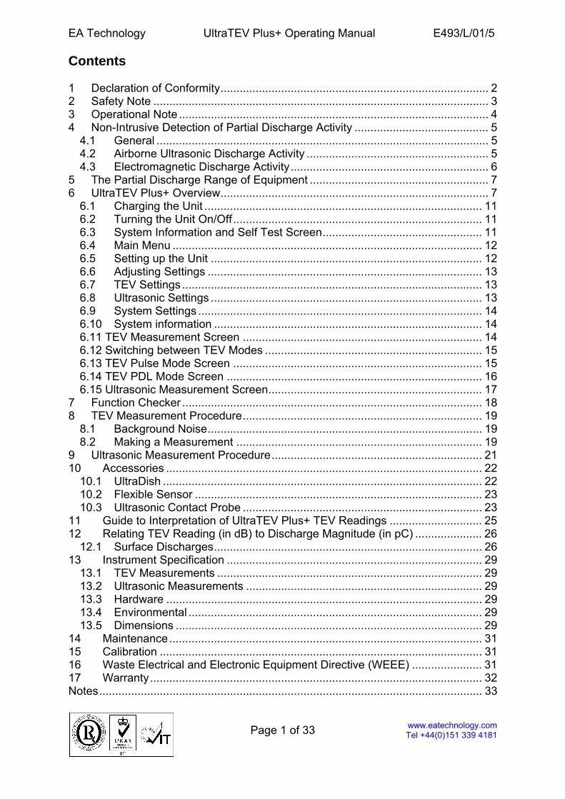
Contents 1 Declaration of Conformity.................................................................................... 2 2 Safety Note ......................................................................................................... 3 3 Operational Note ................................................................................................. 4 4 Non-Intrusive Detection of Partial Discharge Activity .......................................... 5
4.1 General ........................................................................................................ 5 4.2 Airborne Ultrasonic Discharge Activity ......................................................... 5 4.3 Electromagnetic Discharge Activity.............................................................. 6
5 The Partial Discharge Range of Equipment ........................................................ 7 6 UltraTEV Plus+ Overview.................................................................................... 7
6.1 Charging the Unit ....................................................................................... 11 6.2 Turning the Unit On/Off .............................................................................. 11 6.3 System Information and Self Test Screen.................................................. 11 6.4 Main Menu ................................................................................................. 12 6.5 Setting up the Unit ..................................................................................... 12 6.6 Adjusting Settings ...................................................................................... 13 6.7 TEV Settings .............................................................................................. 13 6.8 Ultrasonic Settings ..................................................................................... 13 6.9 System Settings ......................................................................................... 14 6.10 System information .................................................................................... 14 6.11 TEV Measurement Screen ........................................................................... 14 6.12 Switching between TEV Modes .................................................................... 15 6.13 TEV Pulse Mode Screen .............................................................................. 15 6.14 TEV PDL Mode Screen ................................................................................ 16 6.15 Ultrasonic Measurement Screen................................................................... 17
7 Function Checker .............................................................................................. 18 8 TEV Measurement Procedure........................................................................... 19
8.1 Background Noise...................................................................................... 19 8.2 Making a Measurement ............................................................................. 19
9 Ultrasonic Measurement Procedure.................................................................. 21 10 Accessories ................................................................................................... 22
10.1 UltraDish .................................................................................................... 22 10.2 Flexible Sensor .......................................................................................... 23 10.3 Ultrasonic Contact Probe ........................................................................... 23
11 Guide to Interpretation of UltraTEV Plus+ TEV Readings ............................. 25 12 Relating TEV Reading (in dB) to Discharge Magnitude (in pC) ..................... 26
12.1 Surface Discharges.................................................................................... 26 13 Instrument Specification ................................................................................ 29
13.1 TEV Measurements ................................................................................... 29 13.2 Ultrasonic Measurements .......................................................................... 29 13.3 Hardware ................................................................................................... 29 13.4 Environmental ............................................................................................ 29 13.5 Dimensions ................................................................................................ 29
14 Maintenance.................................................................................................. 31 15 Calibration ..................................................................................................... 31 16 Waste Electrical and Electronic Equipment Directive (WEEE) ...................... 31 17 Warranty........................................................................................................ 32 Notes........................................................................................................................ 33
EA Technology UltraTEV Plus+ Operating Manual E493/L/01/5
Page 2 of 33
www.eatechnology.com Tel +44(0)151 339 4181
1 Declaration of Conformity Manufacturers Name: EA Technology Ltd, Manufacturers Address: Capenhurst Technology Park Capenhurst Chester CH1 6ES
UK Type of Equipment: UltraTEV Plus+ Model Number: UTP1 I hereby declare that the equipment specified above conforms to the provisions of the EC DIRECTIVE 89/336/EEC on Electromagnetic Compatibility (EMC). Having met the requirements of the following standards;
EN 61000-6-2: 2001 IMMUNITY STANDARD (INDUSTRIAL ENVIRONMENT)
EN 61000-6-3:2001 EMISSION STANDARD (RESIDENTIAL, COMMERCIAL and LIGHT INDUSTRY ENVIRONMENT)
Robert Davis, Managing Director
EA Technology UltraTEV Plus+ Operating Manual E493/L/01/5
Page 3 of 33
www.eatechnology.com Tel +44(0)151 339 4181
2 Safety Note The UltraTEV Plus+ is designed to detect partial discharge sources in Medium/High Voltage (MV/HV) Plant. If no discharges are detected, this does not necessarily imply that an item of MV/HV Plant is discharge free. Discharge sites often have dormant periods and insulation structures can fail through causes other than those attributable to partial discharges. If discharges of considerable magnitude are detected in plant that is connected directly to the medium/high voltage power system, the authority responsible for the plant should be notified immediately.
Warning The UltraTEV Plus+ is designed for use at ground potential only. • When testing electrical plant ensure that the metalwork is earthed before taking
any measurements. • Maintain safety clearances between structures at high voltage and the
instrument, its probes and the operator at all times. • Adhere strictly to local safety procedures. • Do not make measurements when there are electrical storms in the vicinity. • Do not make measurements immediately following the energisation of a circuit. • Do not disturb plant during measurements either mechanically (e.g. by shaking or
striking it), electrically (e.g. by increasing the voltage) or physically (e.g. by applying heat).
• Do not operate the instrument or its accessories in an explosive atmosphere. • Mains supply voltages are present within the battery charger. • This unit contains no user serviceable parts, always return to EA Technology or
your local distributor for service and repair.
EA Technology UltraTEV Plus+ Operating Manual E493/L/01/5
Page 4 of 33
www.eatechnology.com Tel +44(0)151 339 4181
3 Operational Note When using TEV based instruments the following points should be noted: 1) Care must be taken where work is performed in tight corners, where the proximity
of other earth planes will affect the reading. If possible maintain a distance of more than 30cm from metal work which runs perpendicular to the sensor faceplate.
2) Strong electromagnetic fields from mobile phones, RF transmitters, VDUs and
un-screened electronics in the frequency range DC to 1GHz can have an effect on the readings. A measure of local fields can be obtained by holding the UltraTEV Plus+ in free-air at least 1 metre away from any conducting surface.
If you have any specific requirement or operating conditions then please contact: [email protected].
EA Technology UltraTEV Plus+ Operating Manual E493/L/01/5
Page 5 of 33
www.eatechnology.com Tel +44(0)151 339 4181
4 Non-Intrusive Detection of Partial Discharge Activity 4.1 General Partial discharges are electric discharges that do not completely bridge the electrodes. The magnitude of such discharges is usually small; however, they do cause progressive deterioration of insulation that may lead to eventual failure. Non-intrusive partial discharge detection provides a fast and simple to use method for identifying potential sources of insulation failure that could otherwise result in the loss of supply to customers or the endangering of staff or other personnel. A partial discharge emits energy in the following ways:
Electromagnetic: • Radio • Light • Heat Acoustic: • Audio • Ultrasonic Gases: • Ozone • Nitrous oxides
The most practical techniques for non-intrusive testing are based on the detection of the radio frequency part of the electromagnetic spectrum and ultrasonic emissions. The UltraTEV Detector has been specifically developed to enable electromagnetic and ultrasonic activity to be detected in a single simple to use instrument. 4.2 Airborne Ultrasonic Discharge Activity Acoustic emission from partial discharge activity occurs over the whole acoustic spectra. Audible detection is possible but depends on the hearing ability of the individual. Using an instrument to detect the ultrasonic part of the acoustic spectra has several advantages. Instruments are more sensitive than the human ear, are not operator dependent and operating above the audible frequency, are more directional. The most sensitive method of detection is using an airborne ultrasonic microphone centred at 40 kHz. This method is very successful at detecting partial discharge activity provided there is an air passage between the source and the microphone.
EA Technology UltraTEV Plus+ Operating Manual E493/L/01/5
Page 6 of 33
www.eatechnology.com Tel +44(0)151 339 4181
4.3 Electromagnetic Discharge Activity When partial discharge activity occurs within high voltage switchgear insulation it generates electromagnetic waves in the radio frequency range which can only escape from the inside of the switchgear through openings in the metal casing. These openings may be air gaps around covers, or gaskets, or other insulating components. When the electromagnetic wave propagates outside the switchgear it also impinges on the metal casing of the switchgear producing a transient voltage in the external metal cladding of the switchgear. The Transient Earth Voltage (TEV) is a few millivolts to a few volts and lasts only a short time with a rise time of a few nanoseconds. The partial discharge activity may be detected non-intrusively by placing a probe on the outside of the switchgear whilst the switchgear is in service.

EA Technology UltraTEV Plus+ Operating Manual E493/L/01/5
Page 7 of 33
www.eatechnology.com Tel +44(0)151 339 4181
5 The Partial Discharge Range of Equipment The range consists of the UltraTEV Detector, UltraTEV Plus+, UltraMet Plus+, UltraTEV Locator, UltraTEV Monitor, PD Locator (PDL1), UltraTEV Alarm, PD Monitor (PDM03CF).
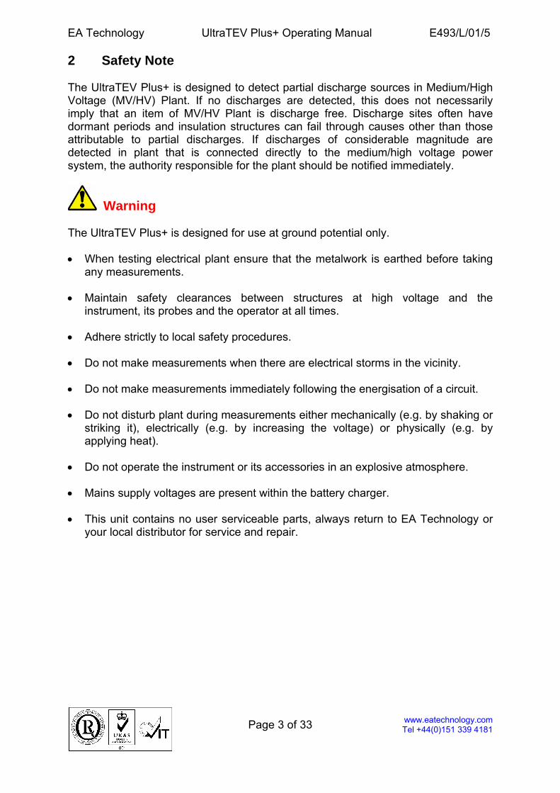
UltraTEV Plus+
The UltraTEV Plus+ is the ultimate hand held instrument for the detection and measurement of partial discharge in switchgear. Both TEV and surface discharges can be detected and are displayed as numerical values on a colour screen. The instrument also has the ability to display the number of PD pulses per cycle, severity levels, maximum levels for internal discharges, and a numerical value for ultrasonic emissions, which can be heard with the supplied headphones.
UltraMet Plus+ A handheld instrument designed to detect ultrasonic emissions produced by surface partial discharge activity in high voltage electricity assets. Optional extras include an UltraDish which allows detection of partial discharge at distance.
EA Technology UltraTEV Plus+ Operating Manual E493/L/01/5
Page 8 of 33
www.eatechnology.com Tel +44(0)151 339 4181
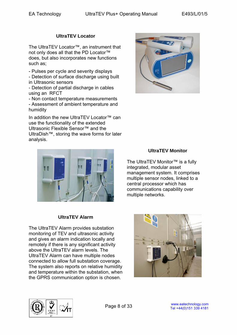
UltraTEV Locator
The UltraTEV Locator™, an instrument that not only does all that the PD Locator™ does, but also incorporates new functions such as;
- Pulses per cycle and severity displays - Detection of surface discharge using built in Ultrasonic sensors - Detection of partial discharge in cables using an RFCT - Non contact temperature measurements - Assessment of ambient temperature and humidity
In addition the new UltraTEV Locator™ can use the functionality of the extended Ultrasonic Flexible Sensor™ and the UltraDish™, storing the wave forms for later analysis.
UltraTEV Monitor
The UltraTEV Monitor™ is a fully integrated, modular asset management system. It comprises multiple sensor nodes, linked to a central processor which has communications capability over multiple networks.
UltraTEV Alarm
The UltraTEV Alarm provides substation monitoring of TEV and ultrasonic activity and gives an alarm indication locally and remotely if there is any significant activity above the UltraTEV alarm levels. The UltraTEV Alarm can have multiple nodes connected to allow full substation coverage. The system also reports on relative humidity and temperature within the substation, when the GPRS communication option is chosen.
EA Technology UltraTEV Plus+ Operating Manual E493/L/01/5
Page 9 of 33
www.eatechnology.com Tel +44(0)151 339 4181
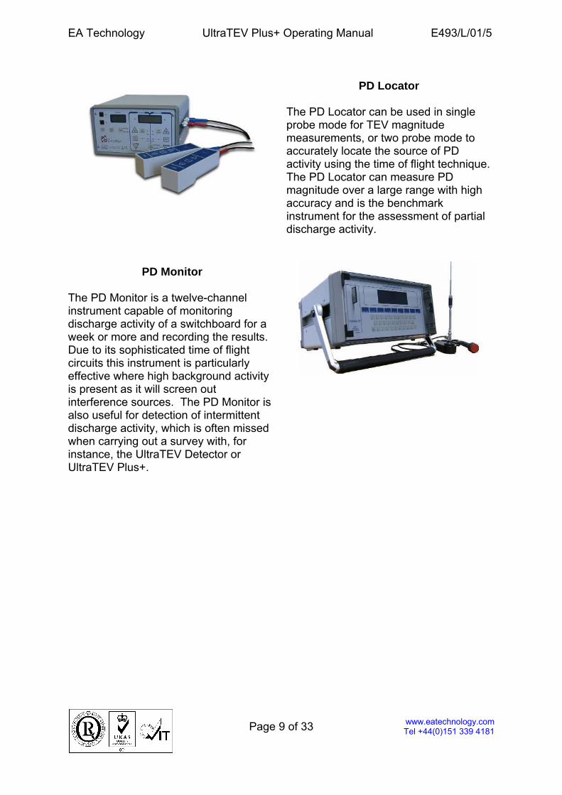
PD Locator
The PD Locator can be used in single probe mode for TEV magnitude measurements, or two probe mode to accurately locate the source of PD activity using the time of flight technique. The PD Locator can measure PD magnitude over a large range with high accuracy and is the benchmark instrument for the assessment of partial discharge activity.
PD Monitor The PD Monitor is a twelve-channel instrument capable of monitoring discharge activity of a switchboard for a week or more and recording the results. Due to its sophisticated time of flight circuits this instrument is particularly effective where high background activity is present as it will screen out interference sources. The PD Monitor is also useful for detection of intermittent discharge activity, which is often missed when carrying out a survey with, for instance, the UltraTEV Detector or UltraTEV Plus+.

EA Technology UltraTEV Plus+ Operating Manual E493/L/01/5
Page 10 of 33
www.eatechnology.com Tel +44(0)151 339 4181
6 UltraTEV Plus+ Overview
TEV Sensor
Colour Display
On/Off Button
Key Pad
Charging LED
Charger Socket
Ultrasonic Sensor
External Sensor Socket
Headphone Socket
EA Technology UltraTEV Plus+ Operating Manual E493/L/01/5
Page 11 of 33
www.eatechnology.com Tel +44(0)151 339 4181
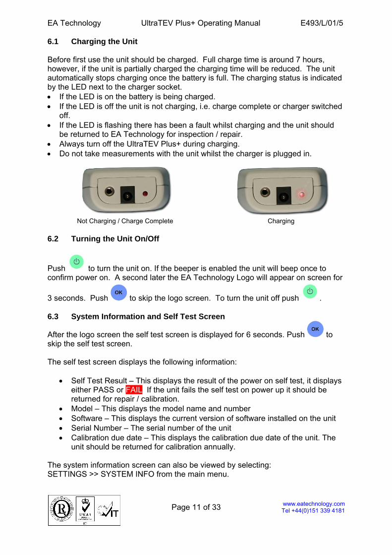
6.1 Charging the Unit Before first use the unit should be charged. Full charge time is around 7 hours, however, if the unit is partially charged the charging time will be reduced. The unit automatically stops charging once the battery is full. The charging status is indicated by the LED next to the charger socket. • If the LED is on the battery is being charged. • If the LED is off the unit is not charging, i.e. charge complete or charger switched
off. • If the LED is flashing there has been a fault whilst charging and the unit should
be returned to EA Technology for inspection / repair. • Always turn off the UltraTEV Plus+ during charging. • Do not take measurements with the unit whilst the charger is plugged in.
Not Charging / Charge Complete Charging
6.2 Turning the Unit On/Off
Push to turn the unit on. If the beeper is enabled the unit will beep once to confirm power on. A second later the EA Technology Logo will appear on screen for
3 seconds. Push to skip the logo screen. To turn the unit off push . 6.3 System Information and Self Test Screen
After the logo screen the self test screen is displayed for 6 seconds. Push to skip the self test screen. The self test screen displays the following information:
• Self Test Result – This displays the result of the power on self test, it displays either PASS or FAIL. If the unit fails the self test on power up it should be returned for repair / calibration.
• Model – This displays the model name and number • Software – This displays the current version of software installed on the unit • Serial Number – The serial number of the unit • Calibration due date – This displays the calibration due date of the unit. The
unit should be returned for calibration annually. The system information screen can also be viewed by selecting: SETTINGS >> SYSTEM INFO from the main menu.
EA Technology UltraTEV Plus+ Operating Manual E493/L/01/5
Page 12 of 33
www.eatechnology.com Tel +44(0)151 339 4181
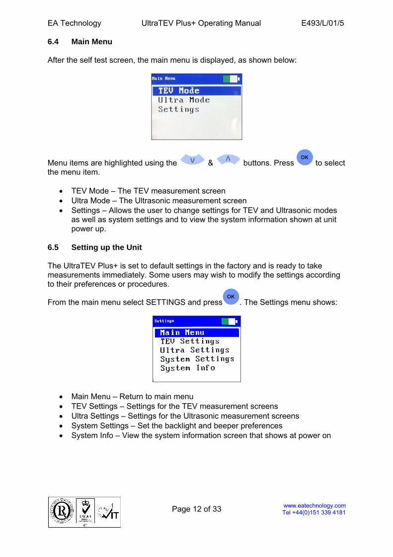
6.4 Main Menu After the self test screen, the main menu is displayed, as shown below:
Menu items are highlighted using the & buttons. Press to select the menu item.
• TEV Mode – The TEV measurement screen • Ultra Mode – The Ultrasonic measurement screen • Settings – Allows the user to change settings for TEV and Ultrasonic modes
as well as system settings and to view the system information shown at unit power up.
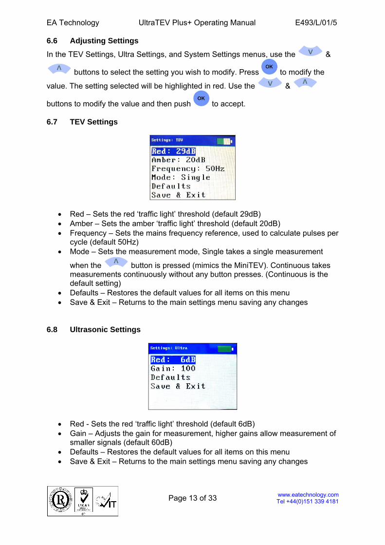
6.5 Setting up the Unit The UltraTEV Plus+ is set to default settings in the factory and is ready to take measurements immediately. Some users may wish to modify the settings according to their preferences or procedures.
From the main menu select SETTINGS and press . The Settings menu shows:
• Main Menu – Return to main menu • TEV Settings – Settings for the TEV measurement screens • Ultra Settings – Settings for the Ultrasonic measurement screens • System Settings – Set the backlight and beeper preferences • System Info – View the system information screen that shows at power on
EA Technology UltraTEV Plus+ Operating Manual E493/L/01/5
Page 13 of 33
www.eatechnology.com Tel +44(0)151 339 4181
6.6 Adjusting Settings
In the TEV Settings, Ultra Settings, and System Settings menus, use the &
buttons to select the setting you wish to modify. Press to modify the
value. The setting selected will be highlighted in red. Use the &
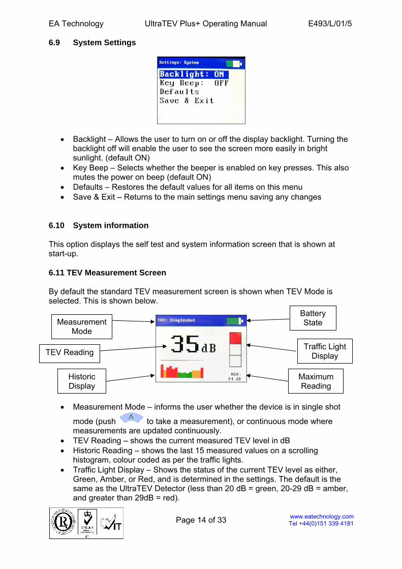
buttons to modify the value and then push to accept. 6.7 TEV Settings
• Red – Sets the red ‘traffic light’ threshold (default 29dB) • Amber – Sets the amber ‘traffic light’ threshold (default 20dB) • Frequency – Sets the mains frequency reference, used to calculate pulses per
cycle (default 50Hz) • Mode – Sets the measurement mode, Single takes a single measurement
when the button is pressed (mimics the MiniTEV). Continuous takes measurements continuously without any button presses. (Continuous is the default setting)
• Defaults – Restores the default values for all items on this menu • Save & Exit – Returns to the main settings menu saving any changes
6.8 Ultrasonic Settings
• Red - Sets the red ‘traffic light’ threshold (default 6dB) • Gain – Adjusts the gain for measurement, higher gains allow measurement of
smaller signals (default 60dB) • Defaults – Restores the default values for all items on this menu • Save & Exit – Returns to the main settings menu saving any changes
EA Technology UltraTEV Plus+ Operating Manual E493/L/01/5
Page 14 of 33
www.eatechnology.com Tel +44(0)151 339 4181
6.9 System Settings
• Backlight – Allows the user to turn on or off the display backlight. Turning the backlight off will enable the user to see the screen more easily in bright sunlight. (default ON)
• Key Beep – Selects whether the beeper is enabled on key presses. This also mutes the power on beep (default ON)
• Defaults – Restores the default values for all items on this menu • Save & Exit – Returns to the main settings menu saving any changes
6.10 System information This option displays the self test and system information screen that is shown at start-up. 6.11 TEV Measurement Screen By default the standard TEV measurement screen is shown when TEV Mode is selected. This is shown below.
• Measurement Mode – informs the user whether the device is in single shot
mode (push to take a measurement), or continuous mode where measurements are updated continuously.
• TEV Reading – shows the current measured TEV level in dB • Historic Reading – shows the last 15 measured values on a scrolling
histogram, colour coded as per the traffic lights. • Traffic Light Display – Shows the status of the current TEV level as either,
Green, Amber, or Red, and is determined in the settings. The default is the same as the UltraTEV Detector (less than 20 dB = green, 20-29 dB = amber, and greater than 29dB = red).
Measurement Mode
TEV Reading
Historic Display
Traffic Light Display
Maximum Reading
Battery State
EA Technology UltraTEV Plus+ Operating Manual E493/L/01/5
Page 15 of 33
www.eatechnology.com Tel +44(0)151 339 4181
• Maximum Reading - the maximum reading obtained since entering the TEV
measurement mode. This can be reset by pushing .
• Push to exit back to the main menu
• To change between TEV mode screens use & as described below 6.12 Switching between TEV Modes TEV measurement has 3 modes of operation, normal mode (as shown above), pulse mode, and PDL mode (as shown below). Both the Normal mode and the Pulse mode can work in either Single or Continuous modes selectable in the Settings menu
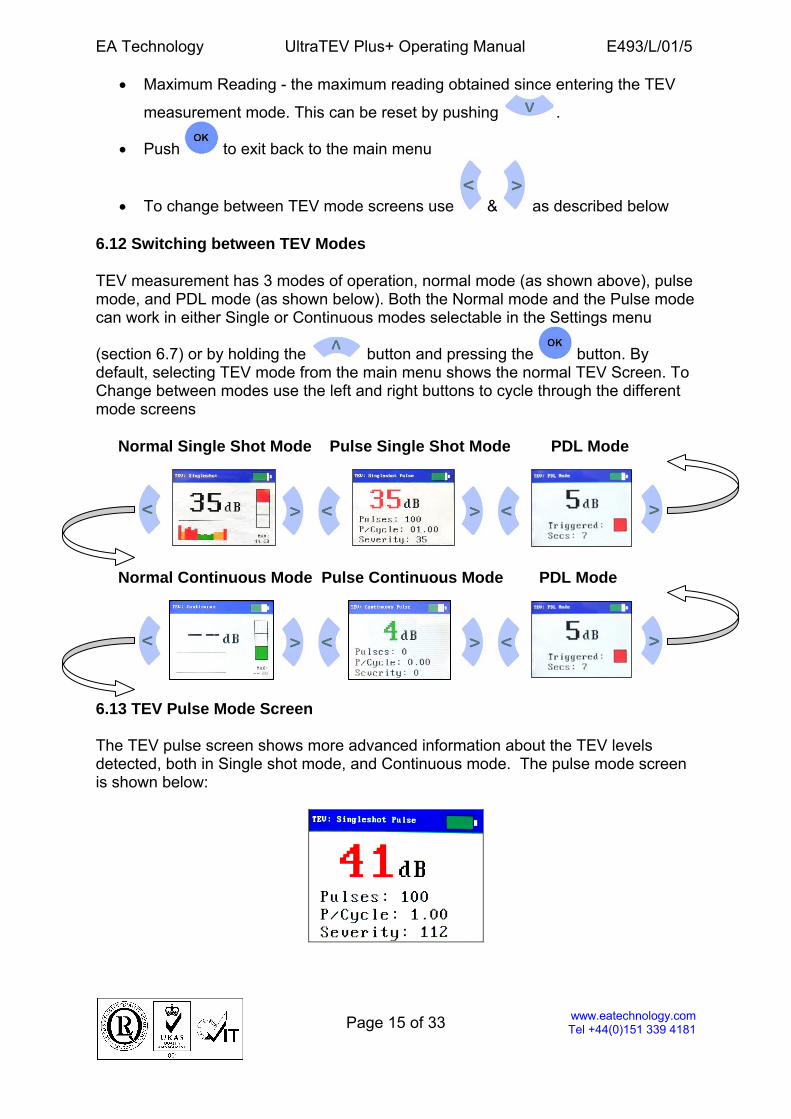
(section 6.7) or by holding the button and pressing the button. By default, selecting TEV mode from the main menu shows the normal TEV Screen. To Change between modes use the left and right buttons to cycle through the different mode screens Normal Single Shot Mode Pulse Single Shot Mode PDL Mode Normal Continuous Mode Pulse Continuous Mode PDL Mode 6.13 TEV Pulse Mode Screen The TEV pulse screen shows more advanced information about the TEV levels detected, both in Single shot mode, and Continuous mode. The pulse mode screen is shown below:
EA Technology UltraTEV Plus+ Operating Manual E493/L/01/5
Page 16 of 33
www.eatechnology.com Tel +44(0)151 339 4181
• Pulses – Shows the pulse count over a 2 second period. (The UltraTEV+ measures pulses over a half second period and multiplies this by 4 to provide the same readout as a MiniTEV).
• P/Cycle – Shows the pulses per cycle based on either a 50 or 60Hz mains frequency.
• Severity – Shows the short term severity (Calculated by TEV magnitude (mV) x Pulses Per Cycle)
• Push to exit back to the main menu
• To change between TEV mode screens use & as described above
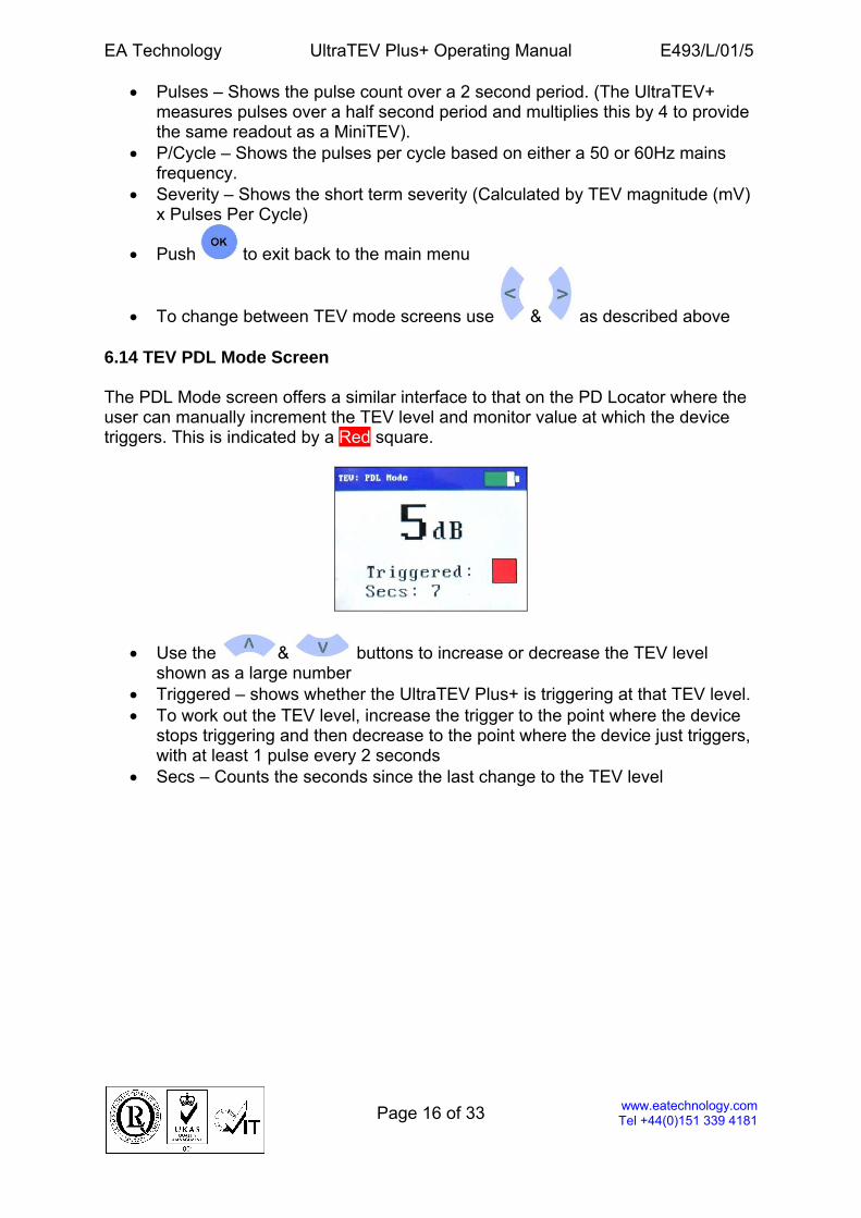
6.14 TEV PDL Mode Screen The PDL Mode screen offers a similar interface to that on the PD Locator where the user can manually increment the TEV level and monitor value at which the device triggers. This is indicated by a Red square.
• Use the & buttons to increase or decrease the TEV level shown as a large number
• Triggered – shows whether the UltraTEV Plus+ is triggering at that TEV level. • To work out the TEV level, increase the trigger to the point where the device
stops triggering and then decrease to the point where the device just triggers, with at least 1 pulse every 2 seconds
• Secs – Counts the seconds since the last change to the TEV level
EA Technology UltraTEV Plus+ Operating Manual E493/L/01/5
Page 17 of 33
www.eatechnology.com Tel +44(0)151 339 4181
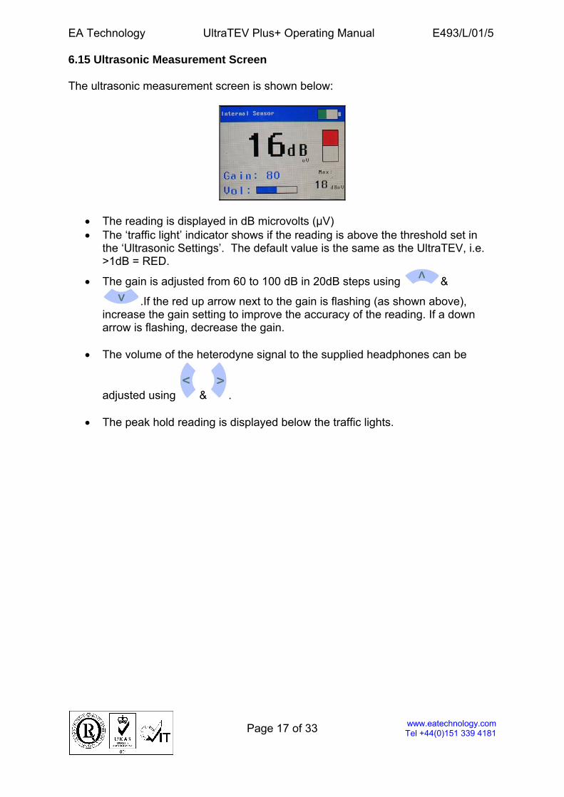
6.15 Ultrasonic Measurement Screen The ultrasonic measurement screen is shown below:
• The reading is displayed in dB microvolts (μV) • The ‘traffic light’ indicator shows if the reading is above the threshold set in
the ‘Ultrasonic Settings’. The default value is the same as the UltraTEV, i.e. >1dB = RED.
• The gain is adjusted from 60 to 100 dB in 20dB steps using &
.If the red up arrow next to the gain is flashing (as shown above), increase the gain setting to improve the accuracy of the reading. If a down arrow is flashing, decrease the gain.
• The volume of the heterodyne signal to the supplied headphones can be
adjusted using & .
• The peak hold reading is displayed below the traffic lights.
EA Technology UltraTEV Plus+ Operating Manual E493/L/01/5
Page 18 of 33
www.eatechnology.com Tel +44(0)151 339 4181
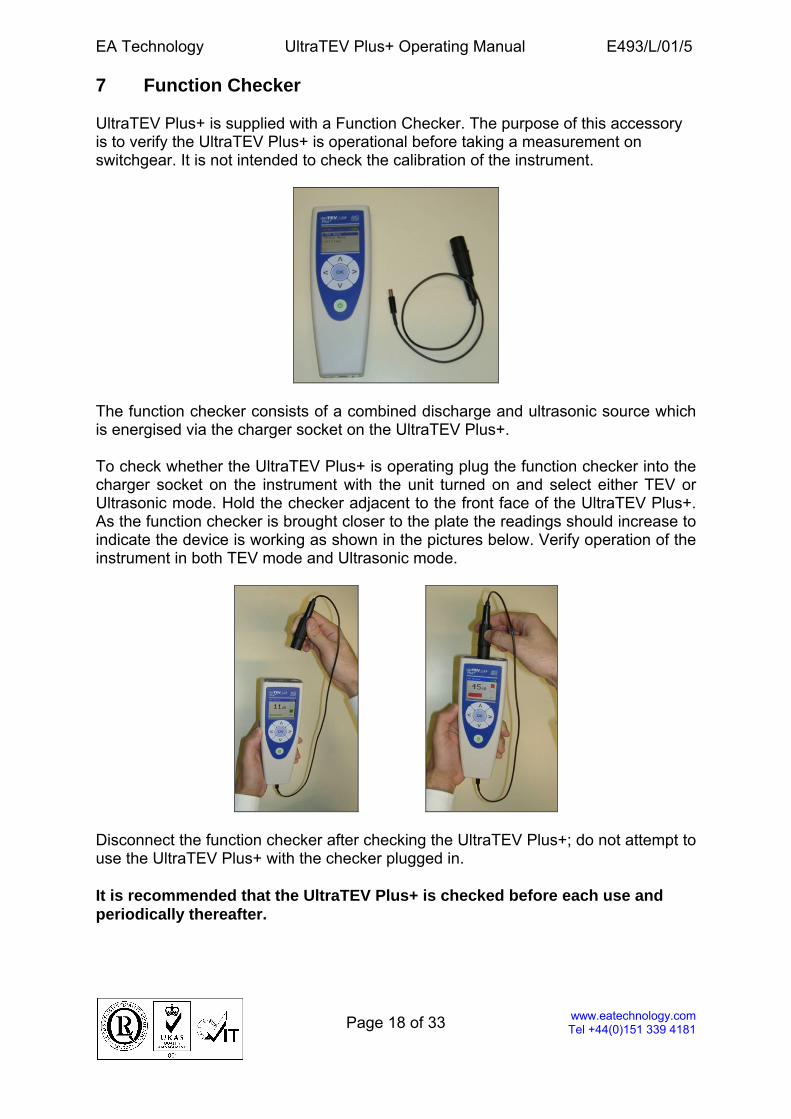
7 Function Checker UltraTEV Plus+ is supplied with a Function Checker. The purpose of this accessory is to verify the UltraTEV Plus+ is operational before taking a measurement on switchgear. It is not intended to check the calibration of the instrument.
The function checker consists of a combined discharge and ultrasonic source which is energised via the charger socket on the UltraTEV Plus+. To check whether the UltraTEV Plus+ is operating plug the function checker into the charger socket on the instrument with the unit turned on and select either TEV or Ultrasonic mode. Hold the checker adjacent to the front face of the UltraTEV Plus+. As the function checker is brought closer to the plate the readings should increase to indicate the device is working as shown in the pictures below. Verify operation of the instrument in both TEV mode and Ultrasonic mode.
Disconnect the function checker after checking the UltraTEV Plus+; do not attempt to use the UltraTEV Plus+ with the checker plugged in. It is recommended that the UltraTEV Plus+ is checked before each use and periodically thereafter.
EA Technology UltraTEV Plus+ Operating Manual E493/L/01/5
Page 19 of 33
www.eatechnology.com Tel +44(0)151 339 4181
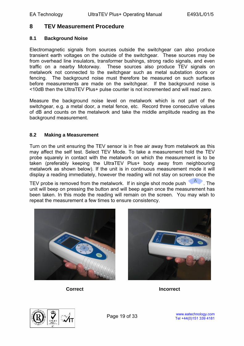
8 TEV Measurement Procedure 8.1 Background Noise Electromagnetic signals from sources outside the switchgear can also produce transient earth voltages on the outside of the switchgear. These sources may be from overhead line insulators, transformer bushings, strong radio signals, and even traffic on a nearby Motorway. These sources also produce TEV signals on metalwork not connected to the switchgear such as metal substation doors or fencing. The background noise must therefore be measured on such surfaces before measurements are made on the switchgear. If the background noise is <10dB then the UltraTEV Plus+ pulse counter is not incremented and will read zero. Measure the background noise level on metalwork which is not part of the switchgear, e.g. a metal door, a metal fence, etc. Record three consecutive values of dB and counts on the metalwork and take the middle amplitude reading as the background measurement. 8.2 Making a Measurement Turn on the unit ensuring the TEV sensor is in free air away from metalwork as this may affect the self test. Select TEV Mode. To take a measurement hold the TEV probe squarely in contact with the metalwork on which the measurement is to be taken (preferably keeping the UltraTEV Plus+ body away from neighbouring metalwork as shown below). If the unit is in continuous measurement mode it will display a reading immediately, however the reading will not stay on screen once the
TEV probe is removed from the metalwork. If in single shot mode push . The unit will beep on pressing the button and will beep again once the measurement has been taken. In this mode the reading will remain on the screen. You may wish to repeat the measurement a few times to ensure consistency.
Correct Incorrect
EA Technology UltraTEV Plus+ Operating Manual E493/L/01/5
Page 20 of 33
www.eatechnology.com Tel +44(0)151 339 4181
Measurements on switchgear are made at the centre of each component of each panel e.g. cable box, CT chamber, busbar chamber, circuit breaker and VT. The position of the circuit breaker or other MV/HV switch is recorded, because if these are in the off position certain components will not be energised and therefore readings will not be valid on such components. Record the first set of readings at each position unless the amplitude is greater than 10dB above the background, and greater than 20dB, and greater than 50 counts. If this is the case, record three consecutive sets of readings.
EA Technology UltraTEV Plus+ Operating Manual E493/L/01/5
Page 21 of 33
www.eatechnology.com Tel +44(0)151 339 4181
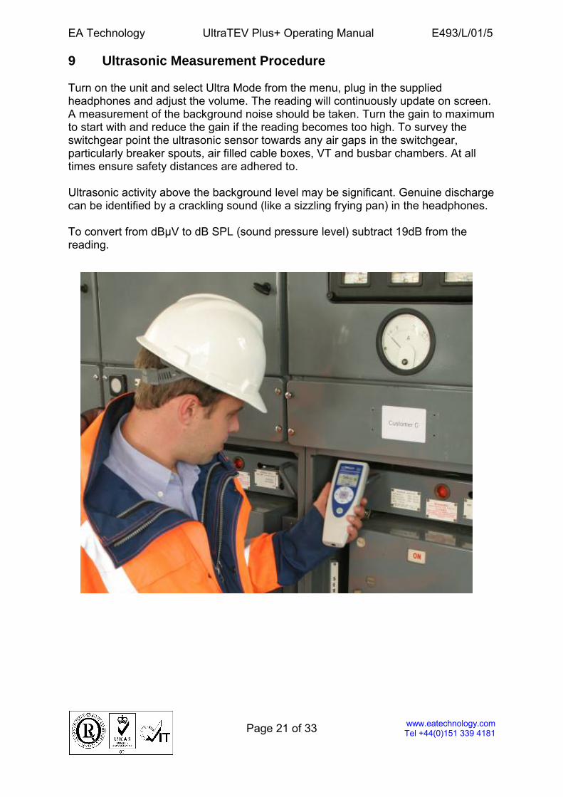
9 Ultrasonic Measurement Procedure Turn on the unit and select Ultra Mode from the menu, plug in the supplied headphones and adjust the volume. The reading will continuously update on screen. A measurement of the background noise should be taken. Turn the gain to maximum to start with and reduce the gain if the reading becomes too high. To survey the switchgear point the ultrasonic sensor towards any air gaps in the switchgear, particularly breaker spouts, air filled cable boxes, VT and busbar chambers. At all times ensure safety distances are adhered to. Ultrasonic activity above the background level may be significant. Genuine discharge can be identified by a crackling sound (like a sizzling frying pan) in the headphones. To convert from dBµV to dB SPL (sound pressure level) subtract 19dB from the reading.

EA Technology UltraTEV Plus+ Operating Manual E493/L/01/5
Page 22 of 33
www.eatechnology.com Tel +44(0)151 339 4181
10 Accessories 10.1 UltraDish
The UltraDish provides a means of detecting discharge sources at a distance. It comprises a transparent parabolic reflector that focuses the ultrasonic sound on to a sensor mounted at the focus point of the reflector. The UltraDish gives an effective increase in gain compared to the built in sensor. The UltraDish can be aimed at the target by using either the optical sight or the built in laser pointer activated by a switch on the handle.
EA Technology UltraTEV Plus+ Operating Manual E493/L/01/5
Page 23 of 33
www.eatechnology.com Tel +44(0)151 339 4181
10.2 Flexible Sensor
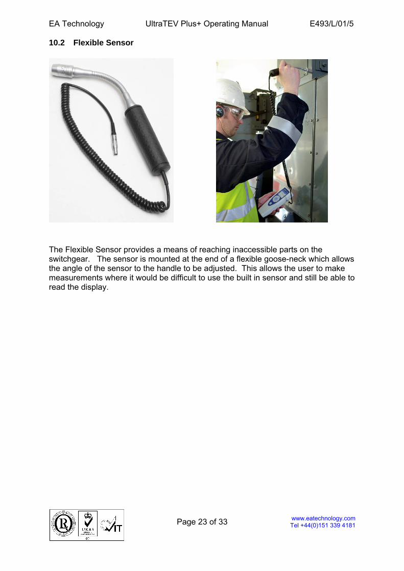
The Flexible Sensor provides a means of reaching inaccessible parts on the switchgear. The sensor is mounted at the end of a flexible goose-neck which allows the angle of the sensor to the handle to be adjusted. This allows the user to make measurements where it would be difficult to use the built in sensor and still be able to read the display.
EA Technology UltraTEV Plus+ Operating Manual E493/L/01/5
Page 24 of 33
www.eatechnology.com Tel +44(0)151 339 4181
10.3 Ultrasonic Contact Probe
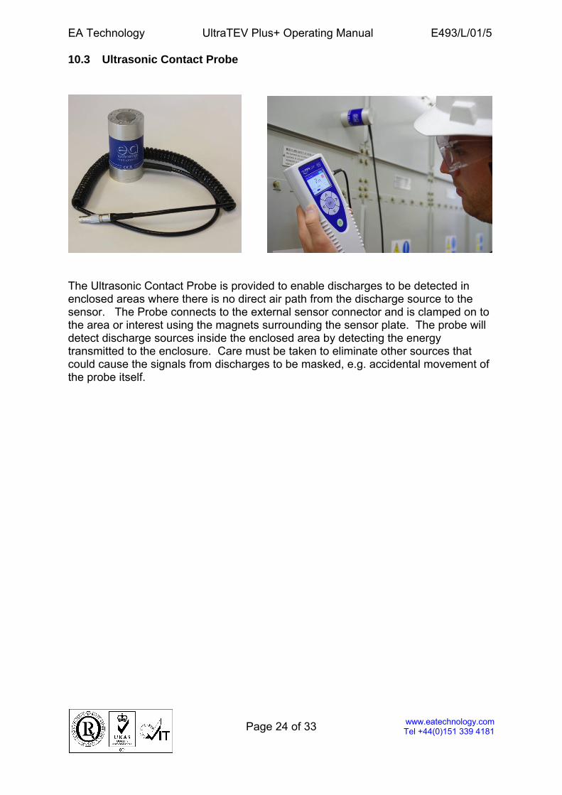
The Ultrasonic Contact Probe is provided to enable discharges to be detected in enclosed areas where there is no direct air path from the discharge source to the sensor. The Probe connects to the external sensor connector and is clamped on to the area or interest using the magnets surrounding the sensor plate. The probe will detect discharge sources inside the enclosed area by detecting the energy transmitted to the enclosure. Care must be taken to eliminate other sources that could cause the signals from discharges to be masked, e.g. accidental movement of the probe itself.
EA Technology UltraTEV Plus+ Operating Manual E493/L/01/5
Page 25 of 33
www.eatechnology.com Tel +44(0)151 339 4181
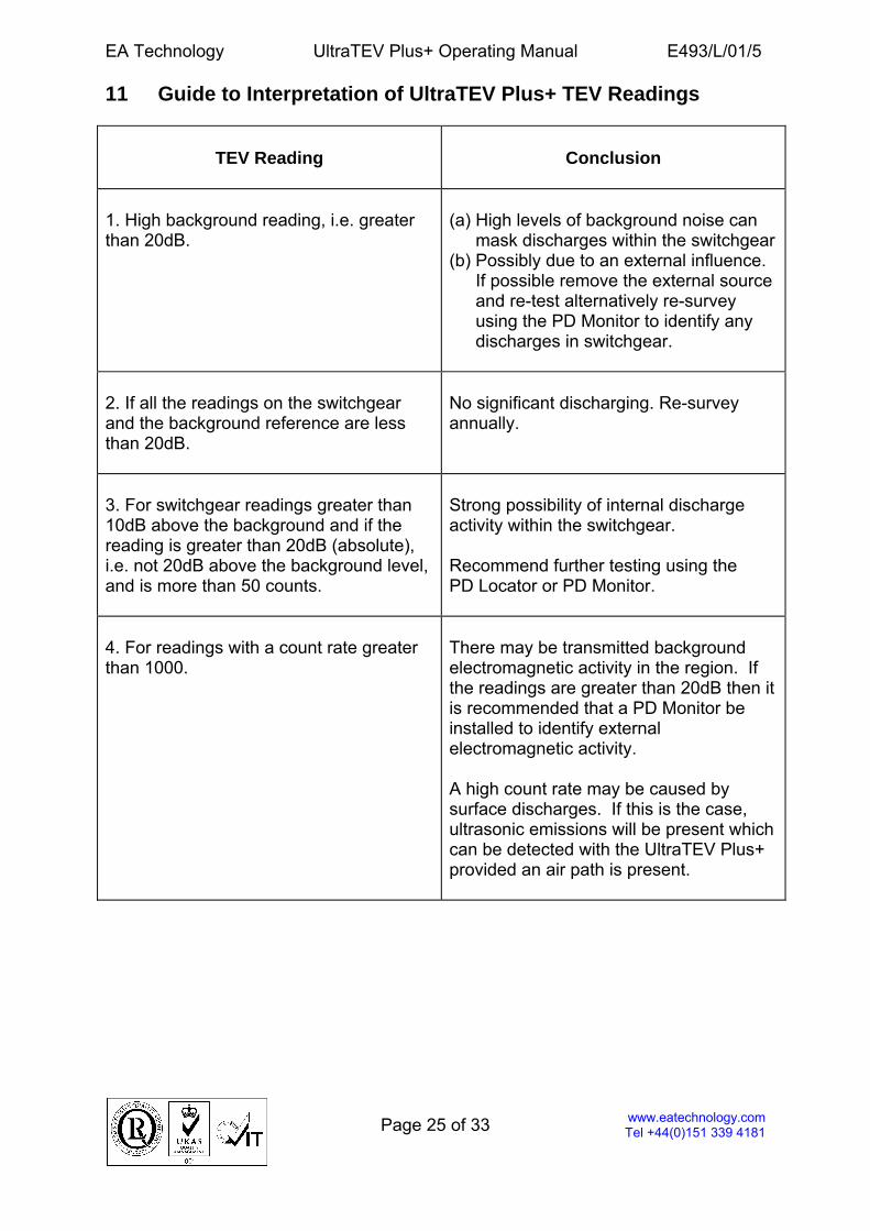
11 Guide to Interpretation of UltraTEV Plus+ TEV Readings
TEV Reading
Conclusion
1. High background reading, i.e. greater than 20dB.
(a) High levels of background noise can
mask discharges within the switchgear (b) Possibly due to an external influence.
If possible remove the external source and re-test alternatively re-survey using the PD Monitor to identify any discharges in switchgear.
2. If all the readings on the switchgear and the background reference are less than 20dB.
No significant discharging. Re-survey annually.
3. For switchgear readings greater than 10dB above the background and if the reading is greater than 20dB (absolute), i.e. not 20dB above the background level, and is more than 50 counts.
Strong possibility of internal discharge activity within the switchgear. Recommend further testing using the PD Locator or PD Monitor.
4. For readings with a count rate greater than 1000.
There may be transmitted background electromagnetic activity in the region. If the readings are greater than 20dB then it is recommended that a PD Monitor be installed to identify external electromagnetic activity. A high count rate may be caused by surface discharges. If this is the case, ultrasonic emissions will be present which can be detected with the UltraTEV Plus+ provided an air path is present.
EA Technology UltraTEV Plus+ Operating Manual E493/L/01/5
Page 26 of 33
www.eatechnology.com Tel +44(0)151 339 4181
12 Relating TEV Reading (in dB) to Discharge Magnitude (in pC) Conventional Partial Discharge detection according to IEC60270, measures the apparent charge transfer from the high voltage conductor system when a discharge occurs. Thus the discharge magnitudes are normally expressed in pico-coulombs (pC). At the detection frequencies used by conventional PD detectors (typically 10 - 300 kHz), all items of high voltage plant, with the exception of long cables, can be considered to be lumped capacitors. The TEV measurement works over the frequency range 3 - 100MHz. At these frequencies high voltage power plant items behave like transmission lines rather than capacitors. The area under the voltage/time curve would be proportional to the charge transfer during the discharge process. TEV sensors measure the peak voltage of the detected transient, rather than the area under the curve. Therefore, it does not measure the charge directly. Furthermore, it is the peak of the wave detected on the external surface of the metal-cladding that is measured and this will be a fraction of that within the cladding. As the pulse travels along the external surfaces of the metal-cladding it disperses, i.e. spreads out. This has the effect of reducing the peak amplitude whilst maintaining the area under the curve. Therefore, the further away from the discharge source the pulse is detected, the greater the attenuation. Clearly the relation between dB and pC is dependent on many factors, most of which are difficult to quantify. Some recent laboratory tests undertaken by an independent party, and field measurements undertaken by EA Technology, on various system components, combining both conventional discharge detection and TEV measurements, yielded the results detailed in the tables on pages 26 and 27. 12.1 Surface Discharges The most successful way of detecting surface discharges is using ultrasonic techniques. Surface discharges produce very low TEV signals compared to internal discharges. In addition, the electromagnetic signals produced by surface discharges are lower in frequency than the operating band of the TEV instruments. This is due to the slower rise times of the waveforms. In many cases the signals will not be picked up by TEV only instruments as they will be lower than the ambient noise levels.
EA Technology UltraTEV Plus+ Operating Manual E493/L/01/5
Page 27 of 33
www.eatechnology.com Tel +44(0)151 339 4181
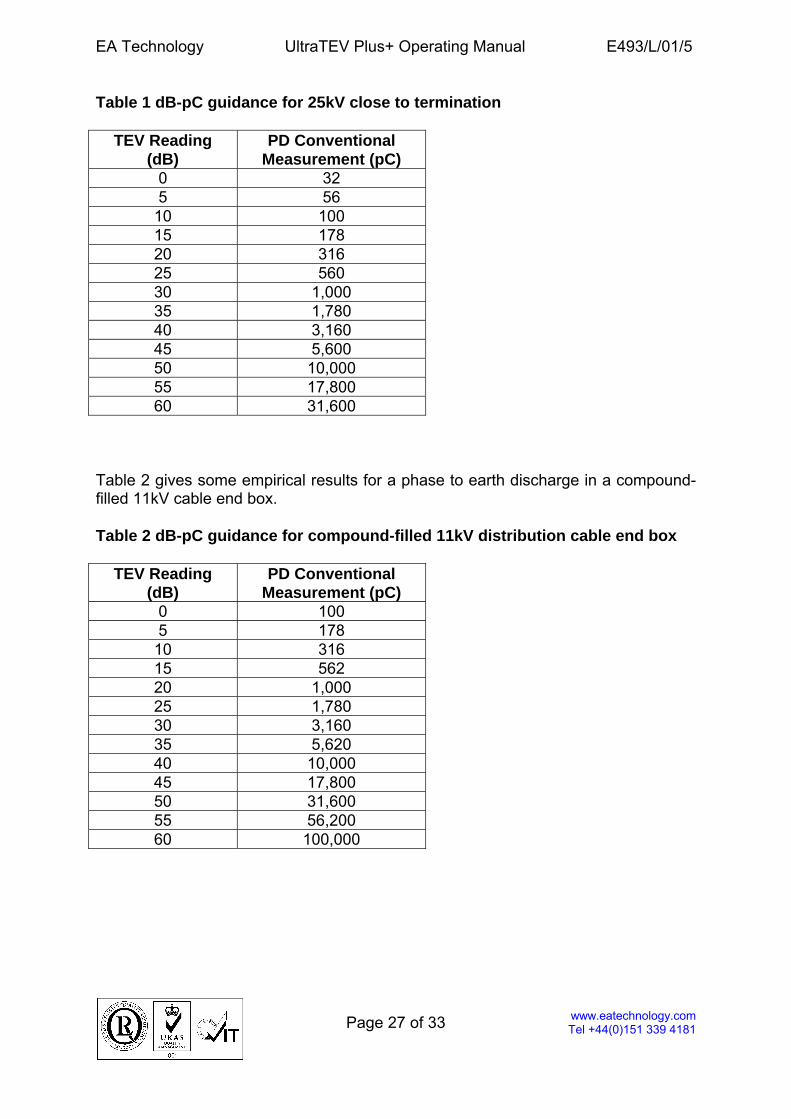
Table 1 dB-pC guidance for 25kV close to termination
TEV Reading (dB)
PD Conventional Measurement (pC)
0 32 5 56
10 100 15 178 20 316 25 560 30 1,000 35 1,780 40 3,160 45 5,600 50 10,000 55 17,800 60 31,600
Table 2 gives some empirical results for a phase to earth discharge in a compound-filled 11kV cable end box. Table 2 dB-pC guidance for compound-filled 11kV distribution cable end box
TEV Reading (dB)
PD Conventional Measurement (pC)
0 100 5 178
10 316 15 562 20 1,000 25 1,780 30 3,160 35 5,620 40 10,000 45 17,800 50 31,600 55 56,200 60 100,000
EA Technology UltraTEV Plus+ Operating Manual E493/L/01/5
Page 28 of 33
www.eatechnology.com Tel +44(0)151 339 4181
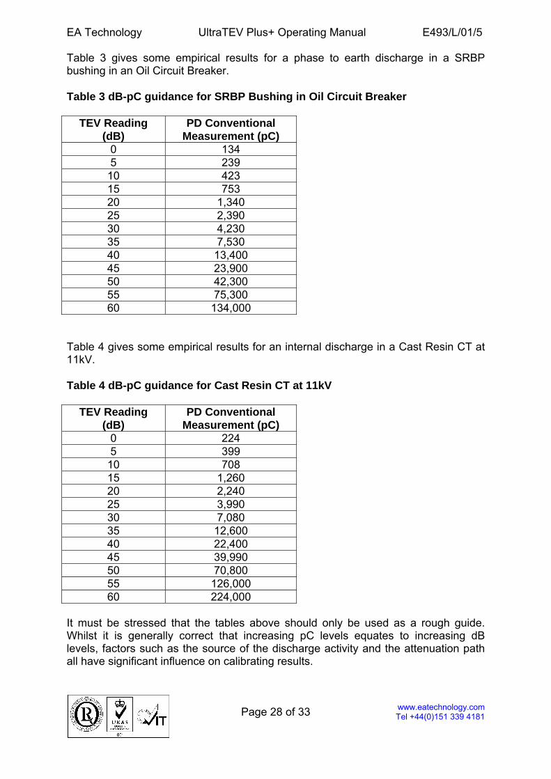
Table 3 gives some empirical results for a phase to earth discharge in a SRBP bushing in an Oil Circuit Breaker. Table 3 dB-pC guidance for SRBP Bushing in Oil Circuit Breaker
TEV Reading (dB)
PD Conventional Measurement (pC)
0 134 5 239
10 423 15 753 20 1,340 25 2,390 30 4,230 35 7,530 40 13,400 45 23,900 50 42,300 55 75,300 60 134,000
Table 4 gives some empirical results for an internal discharge in a Cast Resin CT at 11kV. Table 4 dB-pC guidance for Cast Resin CT at 11kV
TEV Reading (dB)
PD Conventional Measurement (pC)
0 224 5 399
10 708 15 1,260 20 2,240 25 3,990 30 7,080 35 12,600 40 22,400 45 39,990 50 70,800 55 126,000 60 224,000
It must be stressed that the tables above should only be used as a rough guide. Whilst it is generally correct that increasing pC levels equates to increasing dB levels, factors such as the source of the discharge activity and the attenuation path all have significant influence on calibrating results.
EA Technology UltraTEV Plus+ Operating Manual E493/L/01/5
Page 29 of 33
www.eatechnology.com Tel +44(0)151 339 4181
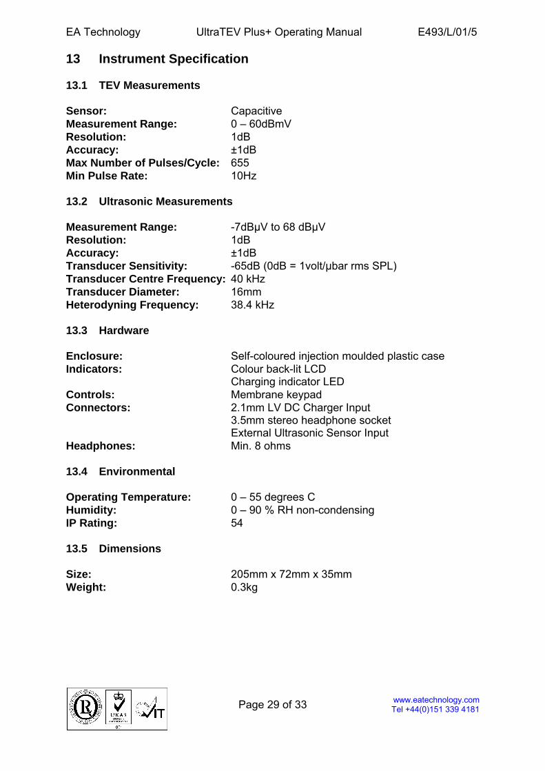
13 Instrument Specification 13.1 TEV Measurements Sensor: Capacitive Measurement Range: 0 – 60dBmV Resolution: 1dB Accuracy: ±1dB Max Number of Pulses/Cycle: 655 Min Pulse Rate: 10Hz 13.2 Ultrasonic Measurements Measurement Range: -7dBµV to 68 dBµV Resolution: 1dB Accuracy: ±1dB Transducer Sensitivity: -65dB (0dB = 1volt/µbar rms SPL) Transducer Centre Frequency: 40 kHz Transducer Diameter: 16mm Heterodyning Frequency: 38.4 kHz 13.3 Hardware Enclosure: Self-coloured injection moulded plastic case Indicators: Colour back-lit LCD Charging indicator LED Controls: Membrane keypad Connectors: 2.1mm LV DC Charger Input 3.5mm stereo headphone socket External Ultrasonic Sensor Input Headphones: Min. 8 ohms 13.4 Environmental Operating Temperature: 0 – 55 degrees C Humidity: 0 – 90 % RH non-condensing IP Rating: 54 13.5 Dimensions Size: 205mm x 72mm x 35mm Weight: 0.3kg
EA Technology UltraTEV Plus+ Operating Manual E493/L/01/5
Page 30 of 33
www.eatechnology.com Tel +44(0)151 339 4181
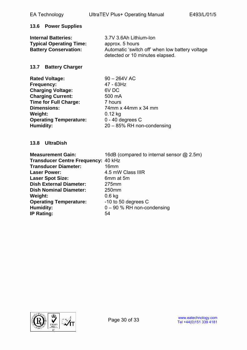
13.6 Power Supplies Internal Batteries: 3.7V 3.6Ah Lithium-Ion Typical Operating Time: approx. 5 hours Battery Conservation: Automatic ‘switch off’ when low battery voltage
detected or 10 minutes elapsed. 13.7 Battery Charger Rated Voltage: 90 – 264V AC Frequency: 47 - 63Hz Charging Voltage: 6V DC Charging Current: 500 mA Time for Full Charge: 7 hours Dimensions: 74mm x 44mm x 34 mm Weight: 0.12 kg Operating Temperature: 0 - 40 degrees C Humidity: 20 – 85% RH non-condensing 13.8 UltraDish Measurement Gain: 16dB (compared to internal sensor @ 2.5m) Transducer Centre Frequency: 40 kHz Transducer Diameter: 16mm Laser Power: 4.5 mW Class IIIR Laser Spot Size: 6mm at 5m Dish External Diameter: 275mm Dish Nominal Diameter: 250mm Weight: 0.6 kg Operating Temperature: -10 to 50 degrees C Humidity: 0 – 90 % RH non-condensing IP Rating: 54
EA Technology UltraTEV Plus+ Operating Manual E493/L/01/5
Page 31 of 33
www.eatechnology.com Tel +44(0)151 339 4181
14 Maintenance It is important that the unit is kept clean and dry. It is not weatherproof. Avoid storage in damp and humid conditions and do not subject it to temperature extremes, excessive vibration or shocks. Do not stand on the case. Internal, rechargeable batteries power the instrument. No attempt should be made to gain access to the internal circuitry of the instrument, or its accessories. Advice should be sought from the manufacturer, or the supplier, if any doubt exists over the equipment's performance or operation. The unit should be cleaned with a damp cloth. If more heavily soiled, a foam cleanser may be used, provided care is taken not to allow fluid to enter the instrument. Abrasive cleaners must not be used. Take care not to scratch the plastic overlay of the front panel, especially in the area of the LCD window. 15 Calibration The recommended calibration interval of 12 months is based on EA Technology’s experience with this product. Your application may require a different calibration interval dependant on the frequency of use. The calibration interval should begin on the date the instrument is placed in service. Proper storage prior to being placed in service will not affect the recommended calibration interval. 16 Waste Electrical and Electronic Equipment Directive (WEEE) EA Technology is a member of an approved compliance scheme as defined by the WEEE directive. When the product reaches the end of its operational life it must be recycled by a licensed waste management operator, or alternatively be returned to EA Technology for recycling.
EA Technology UltraTEV Plus+ Operating Manual E493/L/01/5
Page 32 of 33
www.eatechnology.com Tel +44(0)151 339 4181
17 Warranty This product is warranted against defects in material and workmanship for twelve months from the date of shipment. The battery and accessories (charger, headphones, sensors, etc.) are guaranteed for a period of twelve months. During the warranty period, EA Technology will, at its option, either repair or replace units that prove defective. For warranty service and repair, this product should be returned to EA Technology at the address below. The warranty shall not apply to defects caused by improper maintenance, modification or misuse. Note EA Technology has a policy of continual product development and enhancement. While every effort has been made to ensure the accuracy of this document, there may be minor variations between the details given and the equipment supplied. EA Technology Ltd Capenhurst Technology Park Capenhurst Chester CH1 6ES UK Tel: +44 (0) 151 339 4181 Fax: +44 (0) 151 347 2139
EA Technology UltraTEV Plus+ Operating Manual E493/L/01/5
Page 33 of 33
www.eatechnology.com Tel +44(0)151 339 4181
Notes