Ultrasonic welding of titanium alloy TiAl6V4 to aluminium alloy AA6111
9
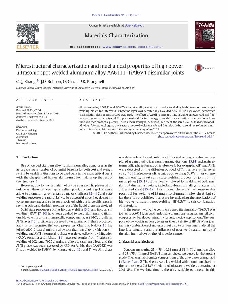
Microstructural characterization and mechanical properties of high power ultrasonic spot welded aluminum alloy AA6111–TiAl6V4 dissimilar joints C.Q. Zhang ⁎, J.D. Robson, O. Ciuca, P.B. Prangnell Materials Science Centre, School of Materials, University of Manchester, Grosvenor Street, Manchester M13 9PL, UK abstract article info Article history: Received 28 May 2014 Received in revised form 1 August 2014 Accepted 3 September 2014 Available online 4 September 2014 Keywords: Dissimilar welding Ultrasonic welding Aluminum Titanium Intermetallic layer Aluminum alloy AA6111 and TiAl6V4 dissimilar alloys were successfully welded by high power ultrasonic spot welding. No visible intermetallic reaction layer was detected in as-welded AA6111/TiAl6V4 welds, even when transmission electron microscopy was used. The effects of welding time and natural aging on peak load and frac- ture energy were investigated. The peak load and fracture energy of welds increased with an increase in welding time and then reached a plateau. The lap shear strength (peak load) can reach the same level as that of similar Al– Al joints. After natural aging, the fracture mode of welds transferred from ductile fracture of the softened alumi- num to interfacial failure due to the strength recovery of AA6111. © 2014 The Authors. Published by Elsevier Inc. This is an open access article under the CC BY license (http://creativecommons.org/licenses/by/3.0/). 1. Introduction Use of welded titanium alloy to aluminum alloy structures in the aerospace has a number of potential benefits for both cost and weight saving by enabling titanium to be used only in the most critical parts, with the cheaper and lighter aluminum alloy making up the rest of the structure [1]. However, due to the formation of brittle intermetallic phases at in- terface and the enormous gap in melting point, the welding of titanium alloys to aluminum alloy remains a major challenge [2–4]. Solid state welding processes are most likely to be successful since they do not in- volve any melting, and so issues associated with the large difference in melting point and the high reaction rate of the liquid phase are avoided. Solid state processes such as friction welding [5,6] and friction stir welding (FSW) [7–10] have been applied to weld aluminum to titani- um. However, a brittle intermetallic compound layer (IMC), usually an Al 3 Ti layer [10], is still often observed after joining with these processes, and this compromises the weld properties. Chen and Nakata [10] lap joined ADC12 cast aluminum alloy to a titanium alloy by friction stir welding, and Al 3 Ti intermetallic phase was detected by X-ray diffraction (XRD). Aonuma and Nakata [11] reported results from friction stir welding of 2024 and 7075 aluminum alloys to titanium alloys, and the Al 3 Ti phase was again detected by XRD. An Al–Mg alloy (AA5052) was friction welded to TiAl6V4 by Kimura et al. [12], and Ti 2 Mg 3 Al 18 phase was detected on the weld interface. Diffusion bonding has also been ex- plored as a method to join aluminum and titanium [13,14] and again in- termetallic phase formation is observed. For example, AlTi and Al 3 Ti were detected on the diffusion bonded Al/Ti interface by Jiangwei et al. [13]. High-power ultrasonic spot welding (USW) is an emerg- ing low energy input solid state welding process for joining thin metal plates [15–17]. It has been employed for welding of both sim- ilar and dissimilar metals, including aluminum alloys, magnesium alloys and steel [15–18]. This process therefore has considerable potential for welding of titanium to aluminum alloy sheet, but so far there is no published literature investigating the application of high-power ultrasonic spot welding (HP-USW) to this combination of materials. In the present work, the commonly used titanium alloy TiAl6V4 was joined to AA6111, an age hardenable aluminum–magnesium–silicon– copper alloy developed primarily for automotive applications. The pur- pose of the work is not only to assess the suitability of HP-USW for join- ing this combination of materials, but also to understand in detail the interface structure and the influence of post-weld natural aging (of the aluminum alloy) on the joint performance. 2. Material and Methods Coupons measuring 25 × 75 × 0.93 mm of 6111-T4 aluminum alloy and 25 × 75 × 1 mm of TiAl6V4 titanium sheets were used for the present study. The nominal chemical compositions of the alloys are summarized in Tables 1 and 2. The sheets were lap welded with aluminum sheet on the top, using a 2.5 kW single reed ultrasonic welder, operating at 20.5 kHz. The welding time is the only variable parameter in this Materials Characterization 97 (2014) 83–91 ⁎ Corresponding author. E-mail addresses: [email protected], [email protected] (C.Q. Zhang). http://dx.doi.org/10.1016/j.matchar.2014.09.001 1044-5803/© 2014 The Authors. Published by Elsevier Inc. This is an open access article under the CC BY license (http://creativecommons.org/licenses/by/3.0/). Contents lists available at ScienceDirect Materials Characterization journal homepage: www.elsevier.com/locate/matchar
-
Upload
acezcq -
Category
Engineering
-
view
80 -
download
8
Transcript of Ultrasonic welding of titanium alloy TiAl6V4 to aluminium alloy AA6111
Materials Characterization 97 (2014) 83–91
Contents lists available at ScienceDirect
Materials Characterization
j ourna l homepage: www.e lsev ie r .com/ locate /matchar
Microstructural characterization andmechanical properties of high powerultrasonic spot welded aluminum alloy AA6111–TiAl6V4 dissimilar joints
C.Q. Zhang ⁎, J.D. Robson, O. Ciuca, P.B. PrangnellMaterials Science Centre, School of Materials, University of Manchester, Grosvenor Street, Manchester M13 9PL, UK
⁎ Corresponding author.E-mail addresses: [email protected], a
http://dx.doi.org/10.1016/j.matchar.2014.09.0011044-5803/© 2014 The Authors. Published by Elsevier Inc
a b s t r a c t
a r t i c l e i n f oArticle history:Received 28 May 2014Received in revised form 1 August 2014Accepted 3 September 2014Available online 4 September 2014
Keywords:Dissimilar weldingUltrasonic weldingAluminumTitaniumIntermetallic layer
Aluminum alloy AA6111 and TiAl6V4 dissimilar alloys were successfully welded by high power ultrasonic spotwelding. No visible intermetallic reaction layer was detected in as-welded AA6111/TiAl6V4 welds, even whentransmission electronmicroscopywas used. The effects of welding time and natural aging on peak load and frac-ture energywere investigated. The peak load and fracture energy of welds increasedwith an increase in weldingtime and then reached a plateau. The lap shear strength (peak load) can reach the same level as that of similar Al–Al joints. After natural aging, the fracture mode of welds transferred from ductile fracture of the softened alumi-num to interfacial failure due to the strength recovery of AA6111.
© 2014 The Authors. Published by Elsevier Inc. This is an open access article under the CC BY license(http://creativecommons.org/licenses/by/3.0/).
1. Introduction
Use of welded titanium alloy to aluminum alloy structures in theaerospace has a number of potential benefits for both cost and weightsaving by enabling titanium to be used only in the most critical parts,with the cheaper and lighter aluminum alloy making up the rest ofthe structure [1].
However, due to the formation of brittle intermetallic phases at in-terface and the enormous gap in melting point, the welding of titaniumalloys to aluminum alloy remains a major challenge [2–4]. Solid statewelding processes are most likely to be successful since they do not in-volve any melting, and so issues associated with the large difference inmelting point and the high reaction rate of the liquid phase are avoided.
Solid state processes such as friction welding [5,6] and friction stirwelding (FSW) [7–10] have been applied to weld aluminum to titani-um. However, a brittle intermetallic compound layer (IMC), usually anAl3Ti layer [10], is still often observed after joiningwith these processes,and this compromises the weld properties. Chen and Nakata [10] lapjoined ADC12 cast aluminum alloy to a titanium alloy by friction stirwelding, and Al3Ti intermetallic phasewas detected by X-ray diffraction(XRD). Aonuma and Nakata [11] reported results from friction stirwelding of 2024 and 7075 aluminum alloys to titanium alloys, and theAl3Ti phase was again detected by XRD. An Al–Mg alloy (AA5052) wasfriction welded to TiAl6V4 by Kimura et al. [12], and Ti2Mg3Al18 phase
[email protected] (C.Q. Zhang).
. This is an open access article under
was detected on theweld interface. Diffusion bonding has also been ex-plored as amethod to join aluminum and titanium [13,14] and again in-termetallic phase formation is observed. For example, AlTi and Al3Tiwere detected on the diffusion bonded Al/Ti interface by Jiangweiet al. [13]. High-power ultrasonic spot welding (USW) is an emerg-ing low energy input solid state welding process for joining thinmetal plates [15–17]. It has been employed for welding of both sim-ilar and dissimilar metals, including aluminum alloys, magnesiumalloys and steel [15–18]. This process therefore has considerablepotential for welding of titanium to aluminum alloy sheet, but sofar there is no published literature investigating the application ofhigh-power ultrasonic spot welding (HP-USW) to this combinationof materials.
In the present work, the commonly used titanium alloy TiAl6V4 wasjoined to AA6111, an age hardenable aluminum–magnesium–silicon–copper alloy developed primarily for automotive applications. The pur-pose of thework is not only to assess the suitability of HP-USW for join-ing this combination of materials, but also to understand in detail theinterface structure and the influence of post-weld natural aging (ofthe aluminum alloy) on the joint performance.
2. Material and Methods
Coupons measuring 25 × 75 × 0.93 mm of 6111-T4 aluminum alloyand 25×75×1mmof TiAl6V4 titanium sheetswere used for the presentstudy. The nominal chemical compositions of the alloys are summarizedin Tables 1 and 2. The sheets were lap welded with aluminum sheet onthe top, using a 2.5 kW single reed ultrasonic welder, operating at20.5 kHz. The welding time is the only variable parameter in this
the CC BY license (http://creativecommons.org/licenses/by/3.0/).
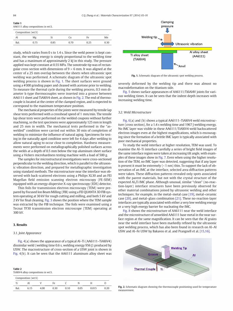
Table 1AA6111 alloy compositions in wt.%.
Composition (wt.%)
Al Mg Si Cu Fe Mn
Bal. 0.75 0.85 0.70 0.25 0.30
Fig. 1. Schematic diagram of the ultrasonic spot welding process.
84 C.Q. Zhang et al. / Materials Characterization 97 (2014) 83–91
study, which varies from 0 s to 1.4 s. Since the weld power is kept con-stant, the welding energy is simply proportional to the welding timeand has a maximum of approximately 2 kJ in this study. The pressureappliedwas kept constant at 0.55MPa. The sonotrode tip was of rectan-gular cross section with dimensions of 9 × 6 mm. It was aligned at thecenter of a 25 mm overlap between the sheets when ultrasonic spotwelding was performed. A schematic diagram of the ultrasonic spotwelding process is shown in Fig. 1. The sheet surfaces were groundusing a #300 grinding paper and cleanedwith acetone prior to welding.To measure the thermal cycle during the welding process, 0.5 mm di-ameter k-type thermocouples were inserted into a groove betweenAA6111 sheet and TiAl6V4 sheet, as shown in Fig. 2. The end of thermo-couple is located at the center of the clamped region, and is expected tocorrespond to the maximum temperature position.
Themechanical properties of the jointsweremeasured by tensile lapshear tests performedwith a crosshead speed of 1 mm/min. The tensilelap shear tests were performed on the welded coupons without furthermachining, so the test specimenswere approximately 125mm in lengthand 25 mm in width. The mechanical tests performed in the “as-welded” condition were carried out within 30 min of completion ofwelding to minimize the influence of natural aging. Specimens for test-ing in the naturally aged condition were left for 4 days after welding toallow natural aging to occur close to completion. Hardness measure-ments were performed on metallographically polished surfaces acrossthe welds at a depth of 0.5 mm below the top aluminum sheet surfaceusing a Vickers microhardness testing machine with a load of 500 g.
The samples for microstructural investigationswere cross-sectionedperpendicular to thewelding direction,which is parallel to the ultrason-ic vibration direction, and prepared for metallographic investigationusing standard methods. The microstructure near the interface was ob-served with back-scattered electrons using a Philips XL30 and an FEIMagellan field emission scanning electron microscopy (FE-SEM)equippedwith an energy-dispersive X-ray spectroscopy (EDS) detector.
Thin foils for transmission electron microscopy (TEM) were pre-paredby Focused Ion BeamMilling (FIB) using a FEI QUANTA3D FIB sys-tem operating at 30 kV for rough cutting andmilling, and both 5 kV and2 kV for final cleaning. Fig. 3 shows the position where the TEM samplewas extracted by the FIB technique. The foils were examined using aTecnai TF30 transmission electron microscope (TEM) operating at300 kV.
3. Results
3.1. Joint Appearance
Fig. 4(a) shows the appearance of a typical Al–Ti (AA6111–TiAl6V4)dissimilar weld (welding time 0.6 s, welding energy 956 J) produced byUSW. The macrostructure of cross-section of a USW joint is shown inFig. 4(b). It can be seen that the AA6111 aluminum alloy sheet was
Table 2TiAl6V4 alloy compositions in wt.%.
Composition (wt.%)
Ti Al V Fe C N H O
Bal. 6.15 4.00 0.30 0.10 0.05 0.015 0.20
severely deformed by the welding tip and there was almost nomacrodeformation on the titanium side.
Fig. 5 shows surface appearances of AA6111/Ti6Al4V joints for vari-ous welding times. It can be seen that the indent depth increases withincreasing welding time.
3.2. Weld Microstructure
Fig. 6(a) and (b) shows a typical AA6111–TiAl6V4 weld microstruc-ture (cross section), for a 1.4 s welding time and 1967 J welding energy.No IMC layer was visible in these AA6111/TiAl6V4 weld backscatteredelectron images even at the highest magnifications, which is encourag-ing since the formation of a brittle IMC layer is typically associated withpoor mechanical properties.
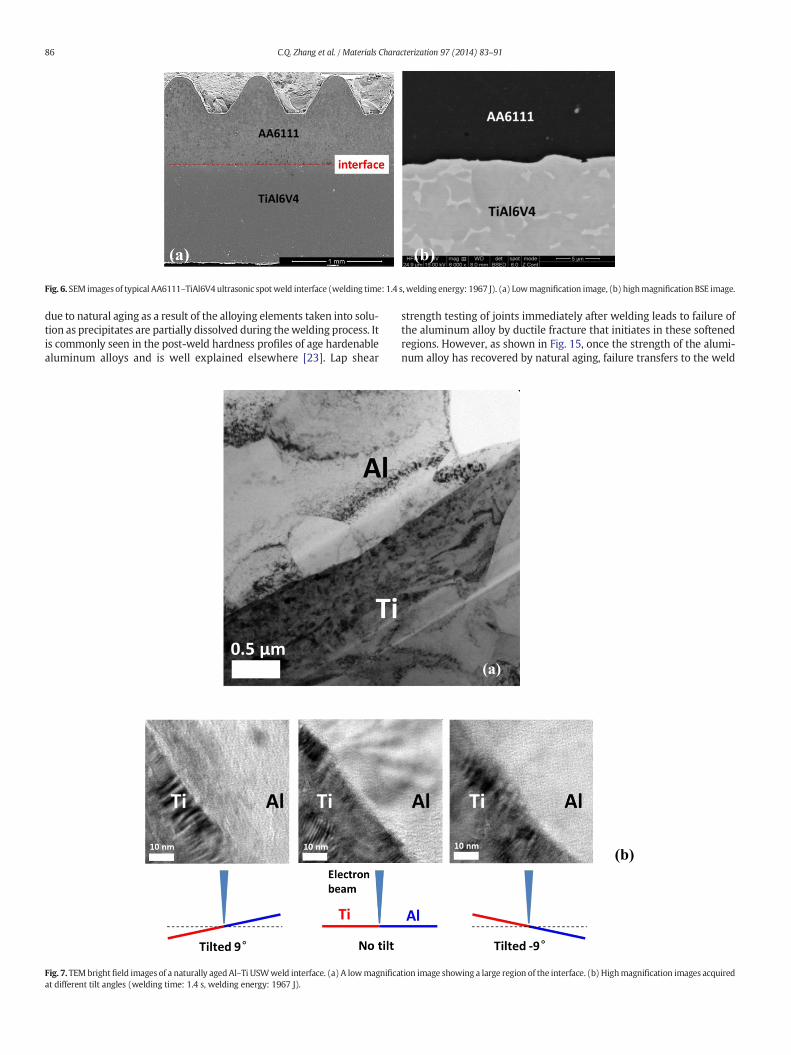
To study the weld interface at higher resolution, TEM was used. Toexamine the Al–Ti interface carefully a series of bright field images ofthe same interface regionwere taken at increasing tilt angle,with exam-ples of these images show in Fig. 7. Even when using the higher resolu-tion of the TEM, no IMC layer was detected, suggesting that if any layeris present it must be extremely (b1 nm) thin. To support the lack of ob-servation of an IMC at the interface, selected area diffraction patternswere taken. These diffraction patterns revealed only spots associatedwith the parent materials, but not with the crystal structure of theexpected Al3Ti IMC phase. Although unusual, similar “clean” (no-reac-tion-layer) interface structures have been previously observed forother material combinations joined by ultrasonic welding and othertechniques; for example, in the metal–metal case [19], metal–ceramiccase [20], and metal–glass combination [21]. These no-reaction-layerinterfaces are typically associatedwith either a very lowwelding energyor a very high energy barrier for nucleating the IMC.
Fig. 8 shows the microstructure of AA6111 near the weld interfaceand themicrostructure of unwelded AA6111 basemetal in the near sur-face region at the same magnification. It can be seen that the Al grainsnear the weld interface have been markedly refined by the ultrasonicspot welding process, which has also been found in research on Al–AlUSW and Al–Fe USW by Bakavos et al. and Prangnell et al. [15,16].
Fig. 2. Schematic diagram showing the thermocouple positioning used for temperaturemeasurement.
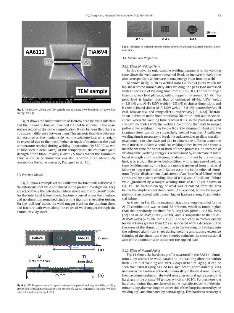
Fig. 3. The location where the TEM sample was extracted (welding time: 1.4 s, weldingenergy: 1967 J).
Fig. 5. Influence of welding time on indent geometry and depth, sample photos (alumi-num side).
85C.Q. Zhang et al. / Materials Characterization 97 (2014) 83–91
Fig. 9 shows the microstructure of TiAl6V4 near the weld interfaceand the microstructure of unwelded TiAl6V4 base metal in the near-surface region at the same magnification. It can be seen that there isno apparent difference between them. This suggests that little deforma-tion occurred on the titanium side near theweld interface, whichmightbe expected due to the much higher strength of titanium at the peaktemperature reached during welding (approximately 520 °C, as willbe discussed in detail later). At this temperature, the estimated yieldstrength of the titanium alloy is over 2.5 times that of the aluminumalloy. A similar phenomenon was also reported in an Al–Fe USWresearch for the same reason by Prangnell et al. [15].
3.3. Fracture Modes
Fig. 10 shows examples of the 2 different fracturemodes observed inthe ultrasonic spot welds produced in the present investigation. Theyare respectively the ‘interfacial failure’ mode and the ‘pull-out’ mode.For the ‘interfacial failure’ mode, fracture occurred across the interface,and no aluminum remained stuck on the titanium sheet after testing.For the ‘pull-out’ mode, the weld nugget stuck on the titanium sheetand fracture path went along the edges of weld nugget through thealuminum alloy sheet.
Fig. 4. (a) Weld appearance of a typical rectangular-tip weld, welding time 0.6 s, weldingenergy956 J. (b)Macrostructure of cross-section of a typical rectangular-tipweld,weldingtime 1.2 s, welding energy 1735 J.
3.4. Mechanical Properties
3.4.1. Effect of Welding TimeIn this study, the only variable welding parameter is the welding
time. Since the weld power remained fixed, an increase in weld timealso corresponds to an increase in total energy input into the weld.
As shown in Fig. 11, in as-welded AA6111/TiAl6V4 joints, which arelap shear tested immediately after welding, the peak load increasedwith an increase of welding time from 0 s to 0.8 s. For times longerthan this, peak load plateaus, with an upper limit around 3.1 kN. Thispeak load is higher than that of optimized Al–Mg USW welds(~2.0 kN) and Al–Fe USW welds (~2.8 kN) of similar dimensions andis close to that of similar Al–Al USWwelds (~3.5 kN) reported by Panteliet al., Bakavos et al. and Prangnell et al. respectively [15,16,22]. The tran-sition in fracture mode from “interfacial failure” to “pull-out”mode oc-curred when the welding time reached 0.8 s, so the plateau in weldstrength coincides with the welding conditions that lead to nuggetpull-out. For welding times below 0.6 s, the aluminum sheet and thetitanium sheet cannot be successfully welded together. A sufficientwelding time is necessary to break the surface oxides to allowmetallur-gical bonding to take place and also to allow some diffusion across theweld interface to form a bond. For welding times below 0.6 s there isinsufficient time for either or both of these processes. An increase ofwelding time (welding energy) is accompanied by an increase of inter-facial strength and the softening of aluminum sheet by the weldingheat, as a result, in the as-welded condition, with an increase of weldingtime (welding energy) the fracture mode transferred from interfacialfailure to nugget pull-out, with failure occurring in the softened alumi-num. Typical displacement–load curves of an “interfacial failure” weld(produced by a short welding time of 0.6 s) and a “pull-out” failureweld (produced by a longer welding time of 0.8 s) are shown inFig. 12. The fracture energy of weld was calculated from the areabelow the displacement–load curve. As expected, failure by nuggetpull-out is associated with a much higher fracture energy than interfa-cial failure.
As shown in Fig. 13, the maximum fracture energy recorded for theAl–Ti combination was around 7.5 kN·mm, which is much higherthan that previously obtained for Al–Mg USW joints (~1.2 kN·mm)[22] and Al–Fe USW joints (~3.8 kN) and is comparable to that of Al–Al USWwelds (~7.8 kN·mm) [15,16]. The reduction in fracture energyfor weld times greater than 1.2 s is associated with a decrease in thethickness of the aluminum sheet due to the welding tool sinking intothe softened aluminum sheet during welding and causing excessivethinning of the aluminum sheet, thereby reducing the cross sectionalarea of the aluminum able to support the applied load.
3.4.2. Effect of Natural AgingFig. 14 shows the hardness profile measured in the AA6111 alumi-
num alloy across the weld parallel to the welding direction withinboth 30 min of welding and after 4 days of natural aging. It can beseen that natural aging has led to a significant (approximately 30%)increase in the hardness of the aluminumalloy in theweld zone. Indeed,themaximumhardness in theweld zone after natural aging exceeds thehardness in the original T4 temper which is ~80 HV. Furthermore, thehardness minima that are observed in the heat affected zone of the alu-minumalloy afterwelding (on either side of the footprint created by thewelding tip) are eliminated by natural aging. This hardness recovery is
(a) (b)
Fig. 6. SEM images of typical AA6111–TiAl6V4 ultrasonic spotweld interface (welding time: 1.4 s,welding energy: 1967 J). (a) Lowmagnification image, (b) highmagnification BSE image.
86 C.Q. Zhang et al. / Materials Characterization 97 (2014) 83–91
due to natural aging as a result of the alloying elements taken into solu-tion as precipitates are partially dissolved during thewelding process. Itis commonly seen in the post-weld hardness profiles of age hardenablealuminum alloys and is well explained elsewhere [23]. Lap shear
Fig. 7. TEMbrightfield images of a naturally agedAl–Ti USWweld interface. (a) A lowmagnificaat different tilt angles (welding time: 1.4 s, welding energy: 1967 J).
strength testing of joints immediately after welding leads to failure ofthe aluminum alloy by ductile fracture that initiates in these softenedregions. However, as shown in Fig. 15, once the strength of the alumi-num alloy has recovered by natural aging, failure transfers to the weld
(a)
(b)
tion image showing a large region of the interface. (b) Highmagnification images acquired
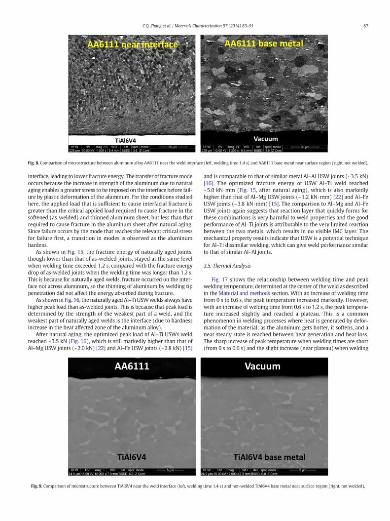
Fig. 8. Comparison of microstructure between aluminum alloy AA6111 near the weld interface (left, welding time 1.4 s) and AA6111 base metal near surface region (right, not welded).
87C.Q. Zhang et al. / Materials Characterization 97 (2014) 83–91
interface, leading to lower fracture energy. The transfer of fracturemodeoccurs because the increase in strength of the aluminum due to naturalaging enables a greater stress to be imposed on the interface before fail-ure by plastic deformation of the aluminum. For the conditions studiedhere, the applied load that is sufficient to cause interfacial fracture isgreater than the critical applied load required to cause fracture in thesoftened (as-welded) and thinned aluminum sheet, but less than thatrequired to cause fracture in the aluminum sheet after natural aging.Since failure occurs by themode that reaches the relevant critical stressfor failure first, a transition in modes is observed as the aluminumhardens.
As shown in Fig. 15, the fracture energy of naturally aged joints,though lower than that of as-welded joints, stayed at the same levelwhen welding time exceeded 1.2 s, compared with the fracture energydrop of as-welded joints when the welding time was longer than 1.2 s.This is because for naturally aged welds, fracture occurred on the inter-face not across aluminum, so the thinning of aluminum by welding tippenetration did not affect the energy absorbed during fracture.
As shown in Fig. 16, the naturally aged Al–TiUSWwelds always havehigher peak load than as-welded joints. This is because that peak load isdetermined by the strength of the weakest part of a weld, and theweakest part of naturally aged welds is the interface (due to hardnessincrease in the heat affected zone of the aluminum alloy).
After natural aging, the optimized peak load of Al–Ti USWs weldreached ~3.5 kN (Fig. 16), which is still markedly higher than that ofAl–Mg USW joints (~2.0 kN) [22] and Al–Fe USW joints (~2.8 kN) [15]
Fig. 9. Comparison of microstructure between TiAl6V4 near the weld interface (left, welding
and is comparable to that of similar metal Al–Al USW joints (~3.5 kN)[16]. The optimized fracture energy of USW Al–Ti weld reached~5.0 kN·mm (Fig. 15, after natural aging), which is also markedlyhigher than that of Al–Mg USW joints (~1.2 kN·mm) [22] and Al–FeUSW joints (~3.8 kN·mm) [15]. The comparison to Al–Mg and Al–FeUSW joints again suggests that reaction layer that quickly forms forthese combinations is very harmful to weld properties and the goodperformance of Al–Ti joints is attributable to the very limited reactionbetween the two metals, which results in no visible IMC layer. Themechanical property results indicate that USW is a potential techniquefor Al–Ti dissimilar welding, which can give weld performance similarto that of similar Al–Al joints.
3.5. Thermal Analysis
Fig. 17 shows the relationship between welding time and peakwelding temperature, determined at the center of theweld as describedin the Material and methods section. With an increase of welding timefrom 0 s to 0.6 s, the peak temperature increased markedly. However,with an increase of welding time from 0.6 s to 1.2 s, the peak tempera-ture increased slightly and reached a plateau. This is a commonphenomenon in welding processes where heat is generated by defor-mation of the material; as the aluminum gets hotter, it softens, and anear steady state is reached between heat generation and heat loss.The sharp increase of peak temperature when welding times are short(from 0 s to 0.6 s) and the slight increase (near plateau) when welding
time 1.4 s) and not-welded TiAl6V4 base metal near surface region (right, not welded).
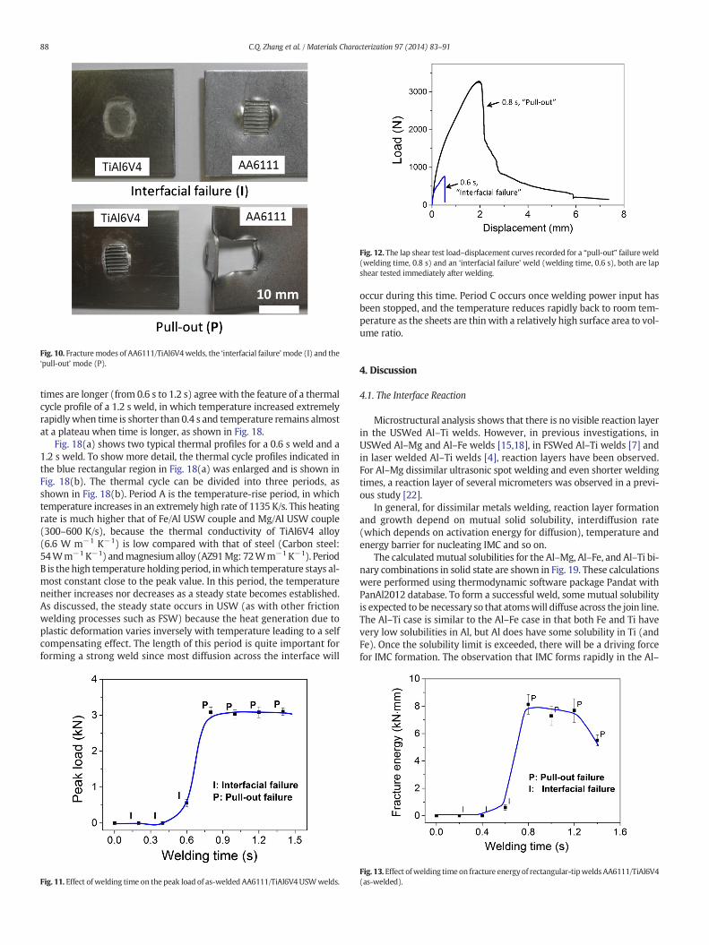
Fig. 10. Fracturemodes of AA6111/TiAl6V4welds, the ‘interfacial failure’mode (I) and the‘pull-out’ mode (P).
Fig. 12. The lap shear test load–displacement curves recorded for a “pull-out” failure weld(welding time, 0.8 s) and an ‘interfacial failure’ weld (welding time, 0.6 s), both are lapshear tested immediately after welding.
88 C.Q. Zhang et al. / Materials Characterization 97 (2014) 83–91
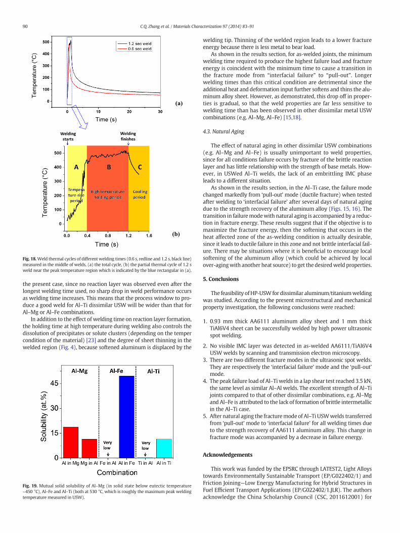
times are longer (from 0.6 s to 1.2 s) agree with the feature of a thermalcycle profile of a 1.2 s weld, in which temperature increased extremelyrapidlywhen time is shorter than 0.4 s and temperature remains almostat a plateau when time is longer, as shown in Fig. 18.
Fig. 18(a) shows two typical thermal profiles for a 0.6 s weld and a1.2 s weld. To show more detail, the thermal cycle profiles indicated inthe blue rectangular region in Fig. 18(a) was enlarged and is shown inFig. 18(b). The thermal cycle can be divided into three periods, asshown in Fig. 18(b). Period A is the temperature-rise period, in whichtemperature increases in an extremely high rate of 1135 K/s. This heatingrate is much higher that of Fe/Al USW couple and Mg/Al USW couple(300–600 K/s), because the thermal conductivity of TiAl6V4 alloy(6.6 W m−1 K−1) is low compared with that of steel (Carbon steel:54Wm−1 K−1) andmagnesiumalloy (AZ91Mg: 72Wm−1 K−1). PeriodB is the high temperature holdingperiod, inwhich temperature stays al-most constant close to the peak value. In this period, the temperatureneither increases nor decreases as a steady state becomes established.As discussed, the steady state occurs in USW (as with other frictionwelding processes such as FSW) because the heat generation due toplastic deformation varies inversely with temperature leading to a selfcompensating effect. The length of this period is quite important forforming a strong weld since most diffusion across the interface will
Fig. 11. Effect of welding time on the peak load of as-welded AA6111/TiAl6V4 USWwelds.
occur during this time. Period C occurs once welding power input hasbeen stopped, and the temperature reduces rapidly back to room tem-perature as the sheets are thin with a relatively high surface area to vol-ume ratio.
4. Discussion
4.1. The Interface Reaction
Microstructural analysis shows that there is no visible reaction layerin the USWed Al–Ti welds. However, in previous investigations, inUSWed Al–Mg and Al–Fe welds [15,18], in FSWed Al–Ti welds [7] andin laser welded Al–Ti welds [4], reaction layers have been observed.For Al–Mg dissimilar ultrasonic spot welding and even shorter weldingtimes, a reaction layer of several micrometers was observed in a previ-ous study [22].
In general, for dissimilar metals welding, reaction layer formationand growth depend on mutual solid solubility, interdiffusion rate(which depends on activation energy for diffusion), temperature andenergy barrier for nucleating IMC and so on.
The calculatedmutual solubilities for the Al–Mg, Al–Fe, and Al–Ti bi-nary combinations in solid state are shown in Fig. 19. These calculationswere performed using thermodynamic software package Pandat withPanAl2012 database. To form a successful weld, somemutual solubilityis expected to be necessary so that atomswill diffuse across the join line.The Al–Ti case is similar to the Al–Fe case in that both Fe and Ti havevery low solubilities in Al, but Al does have some solubility in Ti (andFe). Once the solubility limit is exceeded, there will be a driving forcefor IMC formation. The observation that IMC forms rapidly in the Al–
Fig. 13. Effect ofwelding time on fracture energy of rectangular-tipwelds AA6111/TiAl6V4(as-welded).
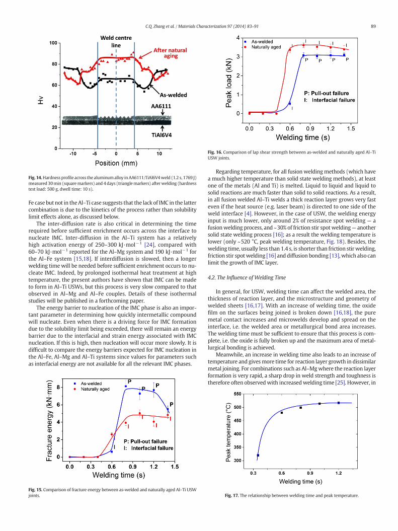
Fig. 14.Hardness profile across the aluminumalloy inAA6111/TiAl6V4weld (1.2 s, 1769 J)measured 30min (squaremarkers) and 4 days (trianglemarkers) afterwelding (hardnesstest load: 500 g, dwell time: 10 s).
Fig. 16. Comparison of lap shear strength between as-welded and naturally aged Al–TiUSW joints.
89C.Q. Zhang et al. / Materials Characterization 97 (2014) 83–91
Fe case but not in theAl–Ti case suggests that the lack of IMC in the lattercombination is due to the kinetics of the process rather than solubilitylimit effects alone, as discussed below.
The inter-diffusion rate is also critical in determining the timerequired before sufficient enrichment occurs across the interface tonucleate IMC. Inter-diffusion in the Al–Ti system has a relativelyhigh activation energy of 250–300 kJ·mol−1 [24], compared with60–70 kJ·mol−1 reported for the Al–Mg system and 190 kJ·mol−1 forthe Al–Fe system [15,18]. If interdiffusion is slowed, then a longerwelding timewill be needed before sufficient enrichment occurs to nu-cleate IMC. Indeed, by prolonged isothermal heat treatment at hightemperature, the present authors have shown that IMC can be madeto form in Al–Ti USWs, but this process is very slow compared to thatobserved in Al–Mg and Al–Fe couples. Details of these isothermalstudies will be published in a forthcoming paper.
The energy barrier to nucleation of the IMC phase is also an impor-tant parameter in determining how quickly intermetallic compoundwill nucleate. Even when there is a driving force for IMC formationdue to the solubility limit being exceeded, there will remain an energybarrier due to the interfacial and strain energy associated with IMCnucleation. If this is high, then nucleation will occur more slowly. It isdifficult to compare the energy barriers expected for IMC nucleation inthe Al–Fe, Al–Mg and Al–Ti systems since values for parameters suchas interfacial energy are not available for all the relevant IMC phases.
Fig. 15. Comparison of fracture energy between as-welded and naturally aged Al–Ti USWjoints.
Regarding temperature, for all fusion weldingmethods (which havea much higher temperature than solid state welding methods), at leastone of the metals (Al and Ti) is melted. Liquid to liquid and liquid tosolid reactions are much faster than solid to solid reactions. As a result,in all fusion welded Al–Ti welds a thick reaction layer grows very fasteven if the heat source (e.g. laser beam) is directed to one side of theweld interface [4]. However, in the case of USW, the welding energyinput is much lower, only around 2% of resistance spot welding — afusionwelding process, and ~30% of friction stir spot welding— anothersolid state welding process [16]; as a result the welding temperature islower (only ~520 °C, peak welding temperature, Fig. 18). Besides, thewelding time, usually less than 1.4 s, is shorter than friction stir welding,friction stir spotwelding [16] and diffusion bonding [13], which also canlimit the growth of IMC layer.
4.2. The Influence of Welding Time
In general, for USW, welding time can affect the welded area, thethickness of reaction layer, and the microstructure and geometry ofwelded sheets [16,17]. With an increase of welding time, the oxidefilm on the surfaces being joined is broken down [16,18], the puremetal contact increases and microwelds develop and spread on theinterface, i.e. the welded area or metallurgical bond area increases.The welding time must be sufficient to ensure that this process is com-plete, i.e. the oxide is fully broken up and the maximum area of metal-lurgical bonding is achieved.
Meanwhile, an increase in welding time also leads to an increase oftemperature and givesmore time for reaction layer growth in dissimilarmetal joining. For combinations such as Al–Mgwhere the reaction layerformation is very rapid, a sharp drop in weld strength and toughness istherefore often observedwith increasedwelding time [25]. However, in
Fig. 17. The relationship between welding time and peak temperature.
(a)
(b)
Fig. 18.Weld thermal cycles of different welding times (0.6 s, redline and 1.2 s, black line)measured in the middle of welds, (a) the total cycle, (b) the partial thermal cycle of 1.2 sweld near the peak temperature region which is indicated by the blue rectangular in (a).
90 C.Q. Zhang et al. / Materials Characterization 97 (2014) 83–91
the present case, since no reaction layer was observed even after thelongest welding time used, no sharp drop in weld performance occursas welding time increases. This means that the process window to pro-duce a good weld for Al–Ti dissimilar USW will be wider than that forAl–Mg or Al–Fe combinations.
In addition to the effect of welding time on reaction layer formation,the holding time at high temperature during welding also controls thedissolution of precipitates or solute clusters (depending on the tempercondition of the material) [23] and the degree of sheet thinning in thewelded region (Fig. 4), because softened aluminum is displaced by the
Fig. 19. Mutual solid solubility of Al–Mg (in solid state below eutectic temperature~450 °C), Al–Fe and Al–Ti (both at 530 °C, which is roughly the maximum peak weldingtemperature measured in USW).
welding tip. Thinning of the welded region leads to a lower fractureenergy because there is less metal to bear load.
As shown in the results section, for as-welded joints, the minimumwelding time required to produce the highest failure load and fractureenergy is coincident with the minimum time to cause a transition inthe fracture mode from “interfacial failure” to “pull-out”. Longerwelding times than this critical condition are detrimental since theadditional heat and deformation input further softens and thins the alu-minum alloy sheet. However, as demonstrated, this drop off in proper-ties is gradual, so that the weld properties are far less sensitive towelding time than has been observed in other dissimilar metal USWcombinations (e.g. Al–Mg, Al–Fe) [15,18].
4.3. Natural Aging
The effect of natural aging in other dissimilar USW combinations(e.g. Al–Mg and Al–Fe) is usually unimportant to weld properties,since for all conditions failure occurs by fracture of the brittle reactionlayer and has little relationship with the strength of base metals. How-ever, in USWed Al–Ti welds, the lack of an embrittling IMC phaseleads to a different situation.
As shown in the results section, in the Al–Ti case, the failure modechanged markedly from ‘pull-out’ mode (ductile fracture) when testedafter welding to ‘interfacial failure’ after several days of natural agingdue to the strength recovery of the aluminum alloy (Figs. 15, 16). Thetransition in failuremodewith natural aging is accompanied by a reduc-tion in fracture energy. These results suggest that if the objective is tomaximize the fracture energy, then the softening that occurs in theheat affected zone of the as-welding condition is actually desirable,since it leads to ductile failure in this zone and not brittle interfacial fail-ure. There may be situations where it is beneficial to encourage localsoftening of the aluminum alloy (which could be achieved by localover-agingwith another heat source) to get thedesiredweld properties.
5. Conclusions
The feasibility ofHP-USW for dissimilar aluminum/titaniumweldingwas studied. According to the present microstructural and mechanicalproperty investigation, the following conclusions were reached:
1. 0.93 mm thick AA6111 aluminum alloy sheet and 1 mm thickTiAl6V4 sheet can be successfully welded by high power ultrasonicspot welding.
2. No visible IMC layer was detected in as-welded AA6111/TiAl6V4USWwelds by scanning and transmission electron microscopy.
3. There are two different fracture modes in the ultrasonic spot welds.They are respectively the ‘interfacial failure’ mode and the ‘pull-out’mode.
4. The peak failure load of Al–Tiwelds in a lap shear test reached 3.5 kN,the same level as similar Al–Al welds. The excellent strength of Al–Tijoints compared to that of other dissimilar combinations, e.g. Al–Mgand Al–Fe is attributed to the lack of formation of brittle intermetallicin the Al–Ti case.
5. After natural aging the fracturemode of Al–Ti USWwelds transferredfrom ‘pull-out’ mode to ‘interfacial failure’ for all welding times dueto the strength recovery of AA6111 aluminum alloy. This change infracture mode was accompanied by a decrease in failure energy.
Acknowledgements
This work was funded by the EPSRC through LATEST2, Light Alloystowards Environmentally Sustainable Transport (EP/G022402/1) andFriction Joining—Low Energy Manufacturing for Hybrid Structures inFuel Efficient Transport Applications (EP/G022402/1.JLR). The authorsacknowledge the China Scholarship Council (CSC, 2011612001) for
91C.Q. Zhang et al. / Materials Characterization 97 (2014) 83–91
financial support and would like to thank Novelis UK and Airbus UK forthe provision of materials.
References
[1] K.H. Rendigs, Aluminium structures used in aerospace — status and prospects, in: J.H. Driver, et al., (Eds.), Aluminium Alloys: Their Physical and Mechanical Properties,Part 4/Supplement, 1997, pp. 11–23.
[2] W.V. Vaidya, et al., Structure–property investigations on a laser beam weldeddissimilar joint of aluminium AA6056 and titanium Ti6Al4V for aeronautical appli-cations part I: local gradients in microstructure, hardness and strength, Mater.Werkst. 40 (8) (2009) 623–633.
[3] Z.H. Song, et al., Interfacial microstructure and mechanical property of Ti6Al4V/A6061 dissimilar joint by direct laser brazing without filler metal and groove,Mater. Sci. Eng. A Struct. Mater. Prop. Microstruct. Process. 560 (2013) 111–120.
[4] S. Chen, et al., Joining mechanism of Ti/Al dissimilar alloys during laser welding-brazing process, J. Alloys Compd. 509 (3) (2011) 891–898.
[5] A. Fuji, K. Ameyama, T.H. North, Influence of silicon in aluminium on the mechanicalproperties of titanium/aluminium friction joints, J. Mater. Sci. 30 (20) (1995)5185–5191.
[6] K. Katoh, H. Tokisue, Effect of insert metal on mechanical properties of frictionwelded 5052 aluminum alloy to pure titanium joint, Keikinzoku/J. Jpn. Inst. LightMet. 54 (10) (2004) 430–435.
[7] Z. Song, et al., Influence of probe offset distance on interfacial microstructure andmechanical properties of friction stir butt welded joint of Ti6Al4V and A6061 dis-similar alloys, Mater. Des. 57 (2014) 269–278.
[8] Y. Wei, et al., Joining aluminum to titanium alloy by friction stir lap welding withcutting pin, Mater. Charact. 71 (2012) 1–5.
[9] U. Dressler, G. Biallas, U. AlfaroMercado, Friction stirwelding of titaniumalloy TiAl6V4to aluminium alloy AA2024-T3, Mater. Sci. Eng. A 526 (1-2) (2009) 113–117.
[10] Y.C. Chen, K. Nakata, Microstructural characterization and mechanical properties infriction stir welding of aluminum and titanium dissimilar alloys, Mater. Des. 30 (3)(2009) 469–474.
[11] M. Aonuma, K. Nakata, Dissimilar metal joining of 2024 and 7075 aluminium alloysto titanium alloys by friction stir welding, Mater. Trans. 52 (5) (2011) 948–952.
[12] M. Kimura, et al., Mechanical properties of friction welded joint between Ti–6Al–4Valloy and Al–Mg alloy (AA5052), Sci. Technol. Weld. Join. 10 (6) (2005) 666–672.
[13] R. Jiangwei, L. Yajiang, F. Tao, Microstructure characteristics in the interface zone ofTi/Al diffusion bonding, Mater. Lett. 56 (5) (2002) 647–652.
[14] Y. Wei, et al., Formation process of the bonding joint in Ti/Al diffusion bonding,Mater. Sci. Eng. A 480 (1–2) (2008) 456–463.
[15] P. Prangnell, F. Haddadi, Y.C. Chen, Ultrasonic spot welding of aluminium to steel forautomotive applications — microstructure and optimisation, Mater. Sci. Technol. 27(3) (2011) 617–624.
[16] D. Bakavos, P.B. Prangnell, Mechanisms of joint and microstructure formation inhigh power ultrasonic spot welding 6111 aluminium automotive sheet, Mater. Sci.Eng. A Struct. Mater. Prop. Microstruct. Process. 527 (23) (2010) 6320–6334.
[17] J. Robson, A. Panteli, P.B. Prangnell, Modelling intermetallic phase formation indissimilar metal ultrasonic welding of aluminium and magnesium alloys, Sci.Technol. Weld. Join. 17 (6) (2012) 447–453.
[18] A. Panteli, et al., The effect of high strain rate deformation on intermetallic reactionduring ultrasonic welding aluminium to magnesium, Mater. Sci. Eng. A 556 (2012)31–42.
[19] H.G. Kim, et al., Microstructural evaluation of interfacial intermetallic compounds inCu wire bonding with Al and Au pads, Acta Mater. 64 (2014) 356–366.
[20] K. Matsunaga, et al., Bonding nature of metal/oxide incoherent interfaces by first-principles calculations, Phys. Rev. B 74 (12) (2006).
[21] C. Iwamoto, Microstructure of aluminum/glass joint bonded by ultrasonic wirewelding, Metall. Mater. Trans. A Phys. Metall. Mater. Sci. 45A (3) (2014) 1371–1375.
[22] A. Panteli, et al., Optimization of aluminium-to-magnesium ultrasonic spot welding,JOM 64 (3) (2012) 414–420.
[23] Y.C. Chen, et al., HAZ development and accelerated post-weld natural ageing inultrasonic spot welding aluminium 6111-T4 automotive sheet, Acta Mater. 60(6–7) (2012) 2816–2828.
[24] X. Cui, et al., Growth kinetics of TiAl3 layer inmulti-laminated Ti–(TiB2/Al) compos-ite sheets during annealing treatment, Mater. Sci. Eng. A 539 (2012) 337–343.
[25] A. Panteli, et al., The effectiveness of surface coatings on preventing interfacialreaction during ultrasonic welding of aluminum to magnesium, Metall. Mater.Trans. A 44 (13) (2013) 5773–5781.