
Ultrasonic flowmeter Sensor type SONO 3300 CT Signal ... · Ultrasonic flowmeter Sensor type SONO...
44
Handbook SAP No. 521H0721 DKFD.PS.029.W1.02 SONOFLO â Ultrasonic flowmeter Sensor type SONO 3300 CT Signal converter SONO 3000 CT [ ] 22.16 98.02 Type approval of the measuring system: TS 27.01-076 *085R9405* Flow Division FLOW DIVISION - SIMPLY BETTER
Transcript of Ultrasonic flowmeter Sensor type SONO 3300 CT Signal ... · Ultrasonic flowmeter Sensor type SONO...

Handbook
SAP No. ��������DKFD.PS.029.W1.02
SONOFLO�
Ultrasonic flowmeterSensor type SONO 3300 CTSignal converter SONO 3000 CT
[ ]
22.1698.02
Type approval of the measuring system:
TS 27.01-076
��������
Flow Division
��������������������������
DKFD.PS.029.W1.02
SONOFLO�
2
1. IntroductionProduct introduction .................................................................................................................. 3Precision measuring system .................................................................................................... 3Approvals .................................................................................................................................. 3Handling .................................................................................................................................... 3System description (CT) .......................................................................................................... 4• Flow sensor SONO 3300 CT ............................................................................................. 4• Signal converter SONO 3000 CT, IP 67, for wall mounting ............................................... 4• Signal converter SONO 3000 CT, IP 65, for wall mounting ............................................... 4• Signal converter SONO 3000 CT, IP 20, front of panel ..................................................... 4• Union connection ................................................................................................................. 4
2. Mode of operationFunction (Flow sensor) ............................................................................................................ 5-6
3. Technical dataFlow sensor SONO 3300 CT ................................................................................................... 7Permissible pressure and temperature .................................................................................... 7Corrosion .................................................................................................................................. 7Coaxial cable ............................................................................................................................ 8Signal converter SONO 3000 CT, IP 67 .................................................................................. 8Signal converter SONO 3000 CT, enclosure IP 20, front of paneland enclosure IP 65, wall mounting ......................................................................................... 9
4. Measuring accuracyAccuracy of SONO CT ............................................................................................................ 10
5. Dimension and weightFlow sensor SONO 3300 CT ................................................................................................... 11Weight of flow sensor SONO 3300 CT .................................................................................... 11Signal converter SONO 3000 CT, IP 67, wall mounting .......................................................... 12Signal converter SONO 3000 CT, IP 65, wall mounting .......................................................... 12Signal converter SONO 3000 CT, IP 20, front of panel .......................................................... 12
6. Project guidanceMounting the flow sensor SONO 3300 CT .............................................................................. 13-14Sizing table OIML R75 approvals and dynamic range. ........................................................... 15Sizing table PTB approvals and dynamic range ...................................................................... 15
7. InstallationInstallation of sensor ................................................................................................................. 16Installation of wall bracket for SONO 3000 signal converter .................................................. 17
8. Electrical connectionsSignal converter SONO 3000 CT, IP 67, wall mounting ......................................................... 18Signal converter SONO 3000 CT, IP 65 and IP 20 ................................................................. 19Frequency output of signal converter for IP 67, IP 65 and IP 20 ........................................... 20Relay mode of signal converter for IP 67, IP 65 and IP 20 ..................................................... 20Signal converter IP 67 version ................................................................................................. 20PTB signal converter in IP 65 version for wall mounting ......................................................... 21IP 65 wall mounting box connection ......................................................................................... 21Installation of SENSORPROM� memory unit ......................................................................... 22
9. CommissioningKeypad and display layout ....................................................................................................... 23Menu build-up, SONO 3000 CT ............................................................................................... 24Main menus .............................................................................................................................. 24Submenus for basic settings .................................................................................................... 25-29Submenus for sensor characteristics ..................................................................................... 30-31Factory settings ........................................................................................................................ 32Start up ...................................................................................................................................... 32Factory settings and measuring ranges ................................................................................. 33
10. Trouble shootingTrouble shooting ....................................................................................................................... 34Fault location guide ................................................................................................................... 35Service mode ............................................................................................................................ 36
11. Calibration/sealingCalibration ................................................................................................................................. 37Data label .................................................................................................................................. 38Verification sealing .................................................................................................................... 39User sealing (General) ............................................................................................................. 40
12. OrderingOrdering .................................................................................................................................... 41Extended ordering form ............................................................................................................ 42Accessories .............................................................................................................................. 43
- this page has been updated 2002.05.17

SONOFLO�
DKFD.PS.029.W1.02 3
1. Introduction
Product introduction
1. Introduction
Danfoss SONOFLO�� ultrasonic flowmeters are designed for measurement of:
• Volume flow rate• Total volume
SONOFLO��ultrasonic flowmeters measure flow in standard volumetric units. Measurement isindependent of changes in liquid temperature, pressure and conductivity.
A time of flight flowmeter is designed for use on clean liquids. A SONOFLO��flowmeter will alsooperate on liquids containing small amounts of gas and solid particles.
The SONO 3000 CT signal converter measures with a high accuracy over a wide measuringrange.
The SONO 3000 signal converter is common to all sensors and is 115/230 V a.c. or 24 V a.c./d.c.compatible.
The sensors have been approved according to EU Directive 97/23/EF dated 29 May 1997 regard-ing fluid in group 1, classified in category III. Design EN 13480.
SONO 3300 CT SONO 3000 CT
Precision measuringsystem
Approvals
Handling
The SONOFLO��ultrasonic flowmeter is a precision measuring system that is "user friendly", butmust be handled and installed in accordance with the instructions given in this manual.
SONOFLO� ultrasonic flowmeters are designed and approved for custody transfer according toPTB, class C and OIML R75, class 4.
The flowmeter must be handled with care. Impact and shock can damage the piezoelectrictransducers located in the sensor.
DKFD.PS.029.W1.02
SONOFLO�
4
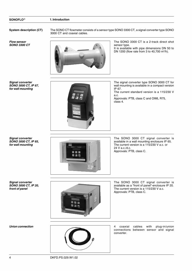
System description (CT) The SONO CT flowmeter consists of a sensor type SONO 3300 CT, a signal converter type SONO3000 CT and coaxial cables.
Flow sensorSONO 3300 CT
The SONO 3300 CT is a 2-track direct shotsensor type.It is available with pipe dimensions DN 50 toDN 1200 (flow rate from 3 to 40,700 m3/h).
Signal converterSONO 3000 CT, IP 67,for wall mounting
The signal converter type SONO 3000 CT forwall mounting is available in a compact versionIP 67.The current standard version is a 115/230 Va.c.Approvals: PTB, class C and OIML R75,class 4.
1. Introduction
Signal converterSONO 3000 CT, IP 65,for wall mounting
The SONO 3000 CT signal converter isavailable in a wall mounting enclosure IP 65.The current version is a 115/230 V a.c. or24 V a.c./d.c.Approvals: PTB, class C.
Signal converterSONO 3000 CT, IP 20,front of panel
The SONO 3000 CT signal converter isavailable as a “front of panel”-enclosure IP 20.The current version is a 115/230 V a.c.Approvals: PTB, class C.
4 coaxial cables with plug-in/unionconnections between sensor and signalconverter.
Union connection

SONOFLO�
DKFD.PS.029.W1.02 5
2. Mode of operation
Measuring with ultrasonics2. Mode of operation
Function
(Flow sensor)
Physical principleA sound wave travelling in the same direction as the liquid flow arrives at point B from point A in ashorter time than a sound wave travelling against the direction of flow (from point B to A).The difference in sound transit time indicates the flow velocity in the pipe.
Measuring principleIn SONOFLO� flowmeters the two ultrasonic transducers are placed at an angle � in relation tothe pipe axis. The transducers function as transmitters and receivers of the ultrasonic signals.Measurement is performed by determining the time the ultrasonic signal takes to travel, with andagainst the flow. The principle can be expressed as follows:
tA, B – t B, A �tV = K –––––-––= K ––
tA, B x tB, A t2
V = Average flow velocityt = Transit timeK = Proportional factor
This measuring principle offers the advantage that it is independent of variations in the actualsound velocity of the liquid, i.e. independent of the temperature.Proportional factor K is determined by wet calibration.
Velocity distribution in pipe Velocity distribution along sound path
Time of flight
Two- track measurementSame principle as 1-track, but with thefollowing advantage:there will be less sensitivity in measuring theflow because of the flow profile after e.g.bends, valves and reductions.

DKFD.PS.029.W1.02
SONOFLO�
6
2. Mode of operation
Module 1:Sensor and SENSORPROM� memory unit.A signal will be transmitted from transducer A and received from transducer B and vs.The SENSORPROM� unit stores calibration data and factory settings and will transmit this data to theASICS module as needed.
Module 2:Front end module.The received analog signals will be digitalized and stored.
Module 3:Module for frequency-, relay- and other outputs.
Module 4:This module calculates the flow characteristics.
Module 5:Keypad and display of signal converter.
Module 6:Power supply.

SONOFLO�
DKFD.PS.029.W1.02 7
Description 2-track sensor with flanges and integrated transducers
Nominal size DN 50, DN 65, DN 80, DN 100, DN 125, DN 150, DN 200,DN 250, DN 300, DN 350, DN 400, DN 500, DN 600, DN 700,DN 800, DN 900, DN 1000, DN 1200
Liquid temperature �10 °C to +200 °C depending on approval
Ambient temperature �10 °C to +160 °C depending on approval
Storage: �40 °C to +85 °C
Enclosure Standard version IP 67
Process connections PN 10 (DN 500 to DN 1200)PN designated PN 16 (DN 50 to DN 1200)EN 1092-1, type 11, B
PN 25 (DN 200 to DN 1000)
PN 40 (DN 50 to DN 500)
Transducers Integrated version welded into pipe
Materials:Pipe DN 50 to DN 150: Steel W1.1131 GS-16Mn5
DN 200 to DN 1200: Steel EN 1.0345 P235GH
Flange DN 50 to DN 1200: Steel group 1E1, EN 1.0038 S235JRG2
Transducers Stainless steel
Material certificate The sensor is supplied as standard with a Danfoss certifi-cate of conformity.Material certificate on wetted parts on request
NDT examination report Available on request
Max. flow velocity 10 m/s
3. Technical data
Flow sensor SONO 3300 CT
3. Technical data
Permissible pressure andtemperature
Maximum permissible pressure and temperature for Danfoss ultrasonic flowmeters can be seenon the sensor label.
Flanges according to PNFlanges and joints as well as related pressure/temperature (p/t) classification have been describedin EN 1092-1.For steel group 1E1: Table 15
No flange bolts and gaskets are supplied. Bolts must comply with EN 1515-2 and gaskets with EN1591-1.
Warning!Exposing the sensors to pressures/temperatures above the limits stated may cause damage. Thesensor construction does not allow any other external action other than what is normal duringcommon mounting in the pipeline. Provide for earthquakes, action of the air etc.
The transducer holders must not be used for any other purpose.
- this page has been updated 2002.08.14
Corrosion The meters have been designed according to EN 13480 with an additional corrosion layer of approx1 mm for steel sensors. Stainless steel sensors do not have an additional layer. The customer isresponsible for checking that the actual medium can be used with the sensor material chosen.

DKFD.PS.029.W1.02
SONOFLO�
8
Signal converterSONO 3000 CT, IP 67
Terminalconnection
Analog output Individually galvanically isolated,isolation voltage 500 V 31 and 32
Measurement of: (optional via menu) Volume flow, sound velocity
Current 0 - 20 mA or 4 - 20 mA
Load < 800 ohm
Time constant 0.8 - 30 s adjustable
Frequency/pulse output Individually galvanically isolated, 50, 51 and 52isolation voltage 500 V
Measurement of: (optional via menu) Volume flow, sound velocity,total volume, total mass
Frequency 0-10 kHz
Time constant 0.8 - 30 s adjustable
Pulse width 50 µs, 500 µs, 5 ms, 20 ms, 50 ms, 100 ms,
500 ms, 1 s, 5 s
Active: Output mode 24 - 30 V d.c./max. 25 mA, (50 µs to 5 s)
(50 ms E.Mech., max. 75 mA if F < Hz)
24 - 30 V d.c./max, 50 mA, (500 Hz to 10 kHz)
Passive: Output mode 5 - 30 V d.c.
Max. current 200 mA
Output mode Output can be either active or passivedepending on electrical connection
Relay Change-over relay (error indication, 44, 45 and 46flow direction, sound velocity limit)
Load 42 V, 0.5 A
Time constant/Hysteresis 5 s/0.5 % F.S.O.
Cut off: Low flow 0-9.9 % F.S.O.
Supply voltage and 115 - 230 V a.c. +10% to -15%, 50-60 Hz,power consumption 10 - 20 VA PE, N and L
Internal counters (totalizers) Two internal counters. Selectable uni- orbidirectional counting (Net flow)
Measurement of Total volume
Display Back-lit with alphanumerical text, 2 x 16 digitsfor indication of: measured values, totalization,settings, error codes and alarms
Enclosure compactEnclosure IP 67 to IEC 529
Material Fibre glass reinforced polyamide
Option: Stainless steel
Ambient temperature Operation: -20 °C to +55 °C
Storage: -40 °C to +85° C
CE-mark EMC CENELEC Emission ImmunityEN 50081-1 EN 50082-2
Low voltage According to EN 60730
Approvals PTB, class C, OIML R75, class 4
3. Technical data
The first 0.5 m of the coaxial cableDiameter � 5.3 mm
Length 0.5 m
Material PTFE
Ambient temperature –200 °C to +200 °C
Coaxial cable from 0.5 m Coaxial cable
Diameter � 8 mm
Length Max. 250 m between sensor and signal converter*
Material PVC
Ambient temperature –40 °C to +100 °C
Coaxial cable
* If distance between signal converter and sensor is more than 30 m, please contact Danfoss.
- this page has been updated 2002.05.17

SONOFLO�
DKFD.PS.029.W1.02 9
Terminalconnection
Analog output Individually galvanically isolated, 31 and 32isolation voltage 500 V
Measurement of: (optional via menu) Volume flow, sound velocity
Current 0 - 20 mA or 4 - 20 mA
Load < 800 ohm
Time constant 0.8 - 30 s adjustable
Frequency/pulse output Individually galvanically isolated, 50, 51 and 52isolation voltage 500 V
Measurement of: (optional via menu) Volume flow, sound velocity,total volume, total mass
Frequency 0-10 kHz
Time constant 0.8 - 30 s adjustable
Pulse width 50 µs, 500 µs, 50 ms E.Mech., 500 ms, 1 s, 5 s
Active: Output mode 24 - 30 V d.c./max. 25 mA, (50 µs to 5 s)
(50 ms E.Mech., max. 75 mA if F < Hz)
24 - 30 V d.c./max. 50 mA, (500 Hz to 10 kHz)
Passive: Output mode 5 - 30 V d.c.
Max. current 200 mA
Output mode Output can be either active or passivedepending on electrical connection
Relay Change-over relay (error indication, 44, 45 and 46flow direction, sound velocity limit)
Load 42 V, 0.5 A
Time constant/Hysteresis 5 s/0.5 % F.S.O.
Cut off: Low flow 0-9.9 % F.S.O.
Supply voltage and power 115/230 V a.c. +10% to -15%, 50-60 Hz,consumption 10 - 20 VA PE, N and L
24 V d.c. +25/-15%, 24 V a.c. ± 15%, 10 VA PE, 1 and 2
Internal counters (totalizers) Two internal counters. Selectable uni- orbidirectional counting (Net flow)
Measurement of Total volume
Display Back-lit with alphanumerical text, 2 x 16 digitsfor indication of: measured values, totalization,settings, error codes and alarms
CE-mark EMC CENELEC Emission ImmunityEN 50081-1 EN 50082-2
Low voltage According to EN 60730
Signal converterSONO 3000 CTenclosure IP 20,front of panel andenclosure IP 65,wall mounting
3. Technical data
Enclosure IP 20 to IEC 529 and DIN 40050
Material Standard 19" insert in aluminium/steel(DIN 41494)
Mechanical vibration 1G 1-800 Hz sinusoidal in all directionsto IEC 68-2-6
Ambient temperature Operation: +0 °C to +55 °C
Storage: -40 °C to +85 °C
Supply voltage and power 115/230 V a.c. +10% to -15%, 50-60 Hz,consumption 10 - 20 VA PE, N and L
Approvals PTB, class C
Enclosure IP 65 to IEC 529 and DIN 40050
Material Standard 19" insert in aluminium/steel(DIN 41494)
Mechanical vibration 1G 1-800 Hz sinusoidal in all directionsto IEC 68-2-6
Ambient temperature Operation: +0 °C to +55 °C
Storage: -40 °C to +85 °C
Supply voltage and power 24 V d.c.+ 25/-15%, 24 V a.c. ±15%, 15 VA, PE, N and Lconsumption cable impedance < 7 ohm at 24 V
115/230 V a.c. +10% to -15%, 50-60 Hz, PE, 1 and 210 - 20 VA
Approvals PTB, class C
Enclosure IP 65,wall mounting
Enclosure IP 20,front of panel

DKFD.PS.029.W1.02
SONOFLO�
10
Flowmeter4. Measuring accuracy
Accuracy of SONO CT SONO CT
SONO CT
4. Measuring accuracy

SONOFLO�
DKFD.PS.029.W1.02 11
5. Dimensions and weight
DN Built-in length L between the flanges Do Pipe wall thickness for*)Size Outside
PN 10 PN 16 PN 25 PN 40 diameter PN 10 PN 16 PN 25 PN 40mm mm mm mm mm mm mm mm
50 - 465 ±3 475 ±3 475 ±3 66.6 - 7.0 7.0 7.0
65 - 460 ±3 475 ±3 475 ±3 78.0 - 7.0 7.0 7.0
80 - 380 ±3 400 ±3 400 ±3 92.0 - 7.0 7.0 7.0
100 - 375 ±3 400 ±3 400 ±3 116.4 - 7.0 7.0 7.0
125 - 375 ±3 400 ±3 400 ±3 143.2 - 7.0 7.0 7.0
150 - 360 ±3 400 ±3 400 ±3 170.4 - 8.0 8.0 8.0
200 - 450 ±4 490 ±4 500 ±4 219.1 - 3.7 4.8 6.5
250 - 600 ±5 575 ±5 600 ±5 273.0 - 4.0 5.3 7.3
300 - 600 ±5 560 ±5 600 ±5 323.9 - 4.4 5.5 8.1
350 - 800 ±5 840 ±5 880 ±5 355.6 - 4.6 6.1 8.6
400 - 875 ±5 925 ±5 975 ±5 406.4 - 4.9 6.6 9.7
500 950 ±6 980 ±6 1050 ±6 1080 ±6 508.0 4.1 5.6 7.9 11.7
600 1075 ±6 1105 ±6 1165 ±6 - 610.0 4.5 6.4 9.1 -
700 1100 ±6 1140 ±6 1190 ±6 - 711.0 5.0 7.2 10.4 -
800 1150 ±6 1180 ±6 1240 ±6 - 813.0 5.6 8.0 11.7 -
900 1200 ±6 1230 ±6 1300 ±6 - 914.0 6.1 8.8 13.3 -
1000 1250 ±6 1300 ±6 1370 ±6 - 1016.0 6.6 9.7 14.3 -
1200 1330 ±6 1360 ±6 - - 1220.0 7.6 11.3 - -
5. Dimensions and weight
Flow sensorSONO 3300 CT
Weight (kg)DN PN 10 PN 16 PN 25 PN 40
50 - 13 14 14
65 - 15 16 16
80 - 18 19 19
100 - 32 35 35
125 - 38 44 44
150 - 45 52 52
200 - 58 70 79
250 - 75 96 117
300 - 92 114 151
350 - 113 145 191
400 - 141 191 274
500 153 207 284 379
600 193 276 363 -
700 262 303 480 -
800 329 400 650 -
900 428 475 835 -
1000 500 594 1078 -
1200 470 732 - -
Weight of flow sensorSONO 3300 CT
- this page has been updated 2002.05.17
*) The stated wall thickness for DN 200 - DN 1200 are minimum values according to the EC Directive on thePressure Equipment 97/23/EC

DKFD.PS.029.W1.02
SONOFLO�
12
Signal converterSONO 3000 CT, IP 67,wall mounting
Add approx. 30 mm on each side for cabling, approx. 2 kg
Signal converterSONO 3000 CT, IP 65,wall mounting
Signal converterSONO 3000 CT, IP 20,front of panel
5. Dimensions and weight
IP 65 wall mounting enclosure
IP 20 panel mounting
Weight 3.5 kg
Weight 2.8 kg

SONOFLO�
DKFD.PS.029.W1.02 13
6. Project guidance
Mounting the flow sensorSONO 3300 CT
L2 L1
Min. 10 x Di 3 x Di
90� bend
L2
L1
Min. 10 x Di 3 x Di
L2 L1
Min. 15 x Di 3 x Di
2 x 90� bends in two planes
2 x 90� bends in same plane
L2 L1
25 x Di
3 x Di
Valve
L2 L1
10 x Di 0 x Di
Reduction
To maximise performance it is necessary to have straight inlet and outlet conditions, and acertain distance between the sensor, bends, pump and valves. It is also important to centre theflowmeter in relation to pipe flanges and gaskets.
Valves must always be placed after the flowmeter. The only exception is when installing thesensor in a vertical pipe. In this case a non return valve below the sensor is necessary to allow thezero-point adjustment. It is important to select a valve, which has no impact on the flow profilewhen fully open.
Find a position on the pipeline where the inlet pipe to the flowmeter has a straight length asspecified below.
For “straight-pipe-sensors“ DN 50 to DN 1200 a fully developed flow profile requires the minimumstraight lengths shown below:
6. Project guidance

DKFD.PS.029.W1.02
SONOFLO�
14
6. Project guidance
Mounting the flow sensorSONO 3300 CT
Find a position on the pipe line where the inlet pipe to the flowmeter has a straight length asspecified below.
Installation in large pipesThe flowmeter can be installed between two reducers (e.g. DIN 28545). At 8° the above pressuredrop curve applies.
Example:A flow velocity of 3 m/s (V) in a sensor with a diameter reduction from DN 200 to DN 100(d1/d2 = 0.5) gives a pressure drop of 9 mbar.

SONOFLO�
DKFD.PS.029.W1.02 15
DN Lowest possible Highest possibleselection selection
Qmin. Qn Qmin. Qnnominal diameter in in in in
mm m3/h m3/h m3/h m3/h50 0.3 15 1.7 8465 0.5 25 2.8 14080 0.8 40 3.8 192
100 1.4 70 6.5 324125 2.0 100 9.8 490150 2.6 130 14.0 720200 3.8 190 24.0 1215250 4.8 240 38.0 1917300 5.4 270 40.0 2000350 6.6 330 40.0 2000400 8.4 420 40.0 2000500 13.0 660 40.0 2000600 20.0 980 40.0 2000700 28.0 1400 40.0 2000
6. Project guidance
Sizing tableOIML R75 approvals
Dynamic range
Sizing tablePTB approvals
DN Minimum flow Maximum flownominal diameter (velocity 0.04 m/s) (velocity 10 m/s)
mm m3/h m3/h50 0.3 8465 0.5 14080 0.8 192
100 1.2 324125 2.0 490150 3.0 720200 5.0 1.215250 8.0 1.917300 11.0 2.740350 13.0 3.261400 17.0 4.309500 28.0 7.069600 40.0 9.923700 55.0 13.854800 72.0 18.096900 92.0 22.9021000 113.0 28.2741200 163.0 40.715
The dynamic range varies depending on the Qn set between: 1:250 and 1:280 but at last 1:10.
The dynamic range is always 1:50.Dynamic range

DKFD.PS.029.W1.02
SONOFLO�
16
With partially full pipes or pipes with free outlet,the flowmeter should be located in a U-pipe.
The following installations should be avoided:• installation at the highest point in the system• installation in vertical pipes with free outlet
Recommended mounting of sensor.
7. Installation
No restriction when vertical mounted. Thesensor must always be completely full of liquid.
7. Installation
Installation of sensor

SONOFLO�
DKFD.PS.029.W1.02 17
Installation of wall bracketfor the SONO 3000 signalconverter
1. Use 75 � coaxial cable between sensor and remote installed converter.2. Mount wall bracket.3. Snap out connection plate, loosen earth connection.4. Connect track 1 transducers to terminals 85..88 and track 2 transducers to terminals 81...84.
Signal wires to even number, screen to odd number.See also chapter 8.
5. Remount earth connection and snap in connection plate.6. Mount power and signal cables and tighten all cable entries to obtain optimum sealing.7. Mount the signal converter on the wall bracket.
7. Installation
Vertical pipe mountingHorizontal pipe mounting
Connec-tion
plate
Earthcable
Wall mounting

DKFD.PS.029.W1.02
SONOFLO�
18
8. Electrical connection
Signal converterSONO 3000 CT,IP 67, wall mounting
The electrical connections must be made in accordance with the diagram in the bottom of thecase. The numbering must correspond to that given in the transducer housing.
Supply voltage 230 V a.c.:115 to 230 V a.c. is connected to terminals 1 and 2.
4-20 mA flow output:A current output signal 4-20 mA can be taken from terminals 31 (+ Ve) and 32 (- Ve). (Remove theshort plug between 31 and 32). Ordinary cable can be used (non-critical lead impedance). Currentoutput load � 800 ohms.The outputs are galvanically isolated.When running cables in areas where electrical noise can occure, the signal from the currentoutput of the unit should be conducted in screened cable to avoid electromagnetic interference.The screen must be connected to the earth terminal in the bottom of the terminal box.
Connect the screen of the coaxial cables toterminals 81, 83, 85 and 87. First connect thefour coaxial cables to the sensor with screwsand tighten using a wrench. See the cableentry with mounted cable and the contactconnection pictured left. Then fasten thecoupling nut to the cable entry for sealing.Install the cables in the terminal box of thesignal converter.
8. Electrical connection
Signalconverter
Sensor

SONOFLO�
DKFD.PS.029.W1.02 19
Signal converterSONO 3000 CT,IP 65 and IP 20
Connect the screens to 81, 83, 85 and 87.
8. Electrical connection
The electrical connections must be made in accordance with the diagram in the bottom of thecase. The numbering must correspond to that given in the transducer housing.
Supply voltage 230 V a.c.:115 to 230 V a.c. is connected to terminals 1 and 2.
4-20 mA flow output:A current output signal 4-20 mA can be taken from terminals 31 (+ Ve) and 32 (- Ve). (Remove theshort plug between 31 and 32). Ordinary cable can be used (non-critical lead impedance). Currentoutput load � 800 ohms.The outputs are galvanically isolated.When running cables in areas where electrical noise can occure, the signal from the currentoutput of the unit should be conducted in screened cable to avoid electromagnetic interference.The screen must be connected to the earth terminal in the bottom of the terminal box.

DKFD.PS.029.W1.02
SONOFLO�
20
Relay mode of signalconverter for IP 67
Relay shown in de-energized position.
Relay 1 Off ONConnection between (De-energized) (Energized)Terminal No. 45-46 44-46
Error "Error" "Normal"
Direction "Forward" "Reverse"
Sound limit Inside range Outside range
Relay mode of signalconverter for IP 65 andIP 20
Relay 1
Relays shown in de-energized position.
Frequency output of signalconverter IP 67, IP 65 andIP 20
If the frequency output load exceeds > 10k� it is recommended a resistor is connected to thefrequency output as shown on the figure above.
Relay 1 Off ONConnection between (De-energized) (Energized)Terminal No. 44-45 45-46
Error "Error" "Normal"
Direction "Forward" "Reverse"
Sound limit Inside range Outside range
Signal converterIP 67 version
Setup prior to installationBy using a 9 V alkaline battery the signal con-verter can be set before final installation. TheSENSORPROM� unit should be first pluggedinto the base of the signal converter. This isespecially advantageous if the flowmeter isinstalled before the system is put into opera-tion.Remove the battery and mount the signal con-verter on the terminal box.
8. Electrical connection
insert 9 V battery here

SONOFLO�
DKFD.PS.029.W1.02 21
PTB signal converterin IP 65 version for wallmounting
1. Mount the IP 65 housing on the wall with four screws.2. Connect the cables to the terminals in the terminal box located separately under the housing.
NoteThe SENSORPROM� memory unit and the electronic unit are factory-mounted in the wallmounting box and sealed in connection with authorized measurements under the supervision ofthe verification authorities.
IP 65 wall mounting boxconnection
8. Electrical connection

DKFD.PS.029.W1.02
SONOFLO�
22
Installation of SENSOR-PROM� memory unit
Each SENSORPROM� memory unit has parameters and is programmed with sensor-specificmeasuring data.This SENSORPROM� unit is inserted at the back of the motherboard in the box (see the illustra-tion below).To identify the SENSORPROM� unit, a label indicates the sensor type and serial number.This data can also be found on the sensor data label.
After installation of the SENSORPROM� unit in the electronic unit, the IP 65/20 enclosure issealed at the factory with authorized measurements under the supervision of the verificationauthorities. This prevents access to the build-in SENSORPROM� unit.In addition the identity of the SENSORPROM� unit can be read on the SONO 3000 CT in themenu SENSOR CHARACTERISTICS (see chapter 9).
At start-up the sensor identity should always be checked in the menu to confirm the sensoridentity is as stated on the data label.
8. Electrical connection
IP 65/20 enclosure for wall mounting without signal converter
IP 67 wall mounting kit
After installation of the SENSORPROM� unit in the IP 67 housing, the signal converter iscovered by a clamp. This clamp is sealed at the factory with authorized measurements under thesupervision of the verification authorities.
SENSORPROM� unit
SENSORPROM� unit

SONOFLO�
DKFD.PS.029.W1.02 23
9. Commissioning
The keypad is used to set the flowmeter. The functions of the keys are as follows:
TOP-UP KEY This key always returns the display to the OPERATORMENU from anywhere in the menu structure.
PAGE FORWARD KEY This key is used to step forwards through the menus.
PAGE BACKWARD KEY This key is used to step backwards through the menus.
CHANGE KEY This key changes the settings or numerical values.
SELECT KEY This key selects the digits to be changed.
LOCK/UNLOCK KEY This key allows the operator to change settings and givesaccess to submenus.
Settings are stored automatically in the signal converter and the SENSORPROM�
memory unit. The settings remain stored in the event of power failure.
Operation of any key illuminates the display. The light automatically turns off 10 minutes after thelast key operation.
Keypad
9. Commissioning
Keypad and display layout
Display The display is alphanumerical and indicates flow values and flowmeter settings.The three fields F, M and L are reserved for the following symbols:
F: If a fault develops, two flashing triangles appear .
M: The symbols on the selected main menu are as follows:
RESET MODE
SERVICE MODE
LANGUAGE SETUP
OPERATOR MENU SETUP
CONVERTER SETUP
L: Intercates the function of the LOCK key by the following symbols:
Ready for change
Valve locked
Access to submenu
RESET MODE: Resetting of totalizers and initialization of settings

DKFD.PS.029.W1.02
SONOFLO�
24
9. Commissioning
MENU BUILD-UP,SONO 3000 CT
MAIN MENUS
Operator menu
Setup menu
Converter setup mode
MENU BUILD-UPThe menu structure of the SONO 3000 CT signal converter is shown in a menu overview with adetailed description of the build-up of each submenu. The structure is in two parts: AnOPERATOR MENU and a SETUP MENU. Access the latter by pressing the TOP-UP key for 2 seconds.
The SETUP MENU provides two options:• VIEW
This is a read-only mode of the flow values and settings.• CHANGE
In the CT version it is only possible to change the flow values and settings with no impact onmeasuring procedure. Access to CHANGE is protected by a user code factory-set at 1000.The data can be changed only when a coding plug has been inserted in the slot at the back ofthe signal converter.In connection with CT measurements this is only possible under the supervision of a represen-tative of the verification authorities (resealing).
The signal converter always starts with a self-test, then proceeding to the basic OPERATORMENU showing the flow rate. The PAGE FORWARD key and the PAGE BACKWARD key are used to step through the OPERATOR MENU.
The SETUP MENU contains the following submenus:• CONVERTER SETUP MODE• RESET MODE• SERVICE MODE• LANGUAGE SETUP• OPERATOR MENU SETUP• USER CODE SETUP
The PAGE FORWARD key is used to step through the main menu. Pressing the LOCK key opens the submenu below. There is no access from the submenu back to the main menu SETUPMENU. To leave a submenu press the TOP-UP key , which returns the program to theOPERATOR MENU. To perform further changes in the SETUP MENU, press the TOP-UP key for 2 seconds and then the PAGE FORWARD key to select the CHANGE mode. Enter the usercode, press the LOCK key , and step through the main menu using the PAGE FORWARD key
until the required menu is reached. Access the submenu by pressing the LOCK key .
This menu contains 3 submenus:• BASIC settings are flow direction, measuring range (volume flow), sound velocity, totalizer 1,
totalizer 2, low flow and forced control. Totalizer 1 and totalizer 2 are the only adjustablesettings. The other settings can be changed only when the coding plug has been inserted, sothey are read-only settings.
• OUTPUT settings are current output 1, frequency/pulse output 1 and relay 1. Relay 1 is the onlyadjustable setting. The other settings can be changed only when the coding plug has beeninserted, so they are read-only settings.
• SENSOR CHARACTERISTICS contains settings and sensor data (such as type and serialnumber), data on calibration, application parameters (such as cable length) and pipe geometrystored in the SENSORPROM� memory unit which cannot be adjusted.
• This data is read automatically from the SENSORPROM� unit when the signal converter isswitched on. Some settings (such as cable length) can be adjusted when the coding plug hasbeen inserted.

SONOFLO�
DKFD.PS.029.W1.02 25
9. Commissioning
Reset mode In this menu the totalizers can be reset, the flowmeter zero point adjusted and the factory settingsre-established.In the CT version these settings can only be changed, adjusted or reset when the coding plug hasbeen inserted, so they are read-only settings.
Service mode In SERVICE MODE the outputs can be set to fixed values (forced outputs) for testing. On leavingSERVICE MODE all settings made in SERVICE MODE are cancelled. See chapter 10, servicemode, for more information on this menu.In the CT version these settings can only be changed, adjusted or reset when the coding plug hasbeen inserted, so they are read-only settings.
Language setup In this menu the menu language is selected. The factory setting is English, German or French.
Operator menu setup Here the information accessible to the operator in the OPERATOR MENU is selected.
User code setup The user code can be changed in this menu.The code is factory-set at 1000. If the user code is lost, the factory setting can be re-established asfollows: Switch off supply voltage, press the TOP-UP key while switching on the supplyvoltage. Release the key after ROM and RAM tests are completed. The user code is now reset at1000.
If the signal converter is left in CONVERTER SETUP for more than 10 minutes without keyoperation, the signal converter automatically reverts to OPERATOR MENU.
Submenus forBASIC SETTINGS
Submenus The below figure gives an overview of the menu structure. Below is a more detailed description ofthe submenus. Use the menu block diagram to step through to required submenu.

DKFD.PS.029.W1.02
SONOFLO�
26
9. Commissioning
Thi
s m
enu
is r
ead-
only
- a
lso
in t
he C
HA
NG
E m
enu.
The
set
tings
can
onl
y be
cha
nged
by
mea
ns o
f a c
onne
cted
cod
ing
plug
and
und
er th
e su
perv
isio
n of
the
calib
ratio
n au
thor
ities
.
MENU BUILD-UP

SONOFLO�
DKFD.PS.029.W1.02 27
The measuring range for sound velocity is set by entering the minimum and maxiumum soundvelocity. If no other limits are defined for sound velocity the measuring range is set using standardvalues. Error relay and error indication are activated when the sound velocity is outside the limitsstated.In the CT version these settings can only be changed, adjusted or reset when the coding plug hasbeen inserted, so they are read-only settings.
Totalizers The two internal totalizers have not been approved for charging purposes, so they can bechanged and are not sealed measurements.
Sound velocity
9. Commissioning
Flow direction Here it is possible to select the flow direction. The factory setting is positive.In the CT version these settings can only be changed, adjusted or reset when the coding plug hasbeen inserted, so they are read-only settings.
Volume flow Use this menu to select the unit for measuring volume flow and the limit of the measuring range(Qn). The application parameters for the selection are set on the basis of a questionnaire availableon request from Danfoss.For unspecified measurements select the factory setting for the unit, m3/h, and set a standardvalue depending on the nominal diameter as the measuring range limit (Qn) (see chapter 6, sizingtable).The Qn value selected corresponds to 100% flow and is based on the limits of all outputs.In the CT version these settings can only be changed, adjusted or reset when the coding plug hasbeen inserted, so they are read-only settings.
DKFD.PS.029.W1.02
SONOFLO�
28
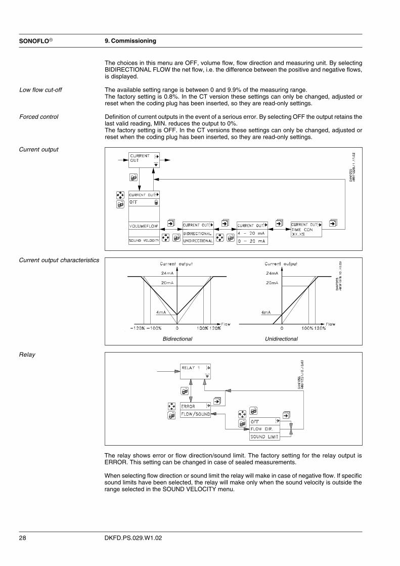
Current output
Current output characteristics
Relay
The relay shows error or flow direction/sound limit. The factory setting for the relay output isERROR. This setting can be changed in case of sealed measurements.
When selecting flow direction or sound limit the relay will make in case of negative flow. If specificsound limits have been selected, the relay will make only when the sound velocity is outside therange selected in the SOUND VELOCITY menu.
9. Commissioning
Bidirectional Unidirectional
The choices in this menu are OFF, volume flow, flow direction and measuring unit. By selectingBIDIRECTIONAL FLOW the net flow, i.e. the difference between the positive and negative flows,is displayed.
The available setting range is between 0 and 9.9% of the measuring range.The factory setting is 0.8%. In the CT version these settings can only be changed, adjusted orreset when the coding plug has been inserted, so they are read-only settings.
Definition of current outputs in the event of a serious error. By selecting OFF the output retains thelast valid reading, MIN. reduces the output to 0%.The factory setting is OFF. In the CT versions these settings can only be changed, adjusted orreset when the coding plug has been inserted, so they are read-only settings.
Low flow cut-off
Forced control

SONOFLO�
DKFD.PS.029.W1.02 29
Frequency output The factory settings are volume flow, bidirectional flow, pulse and pulse values depending on thenominal diameter (see chapter 6, sizing table for OIML R75 and PTB). The applicationparameters for the selection are set on the basis of a questionnaire available on request fromDanfoss.
In the CT version these settings can only be changed, adjusted or reset when the coding plug hasbeen inserted, so they are read-only settings.
Frequency outputcharacteristics
9. Commissioning
Bidirectional Unidirectional

DKFD.PS.029.W1.02
SONOFLO�
30
Submenus forSENSOR CHARACTERISTICS
The characteristic sensor data set on calibration and sealed under the supervision of thecalibration authorities are stored in the SENSORPROM� memory unit and cannot bechanged. They are read-only settings.
Information This menu contains data on the sensor type and nominal diameter, order number and serialnumber.
Calibration options
Application parameters
Correction factor The correction factor allows the user to adjust the calibration factor by ±20% by entering a factorbetween 0.8 and 1.2. The factory setting is 1. In the CT versions these settings can only bechanged, adjusted or reset when the coding plug has been inserted, so they are read-onlysettings.
Cable length Here the length of the coaxial cable (from sensor to signal converter) is entered to compensate forthe time delay occurring in the cables. The cable length is the total length of the coaxial cable inone track. The measuring unit for the cable length is metres with a tolerance of ±0.5 m.The application parameters for the selection are set on the basis the extended ordering form, seechapter 12.In the CT versions these settings can only be changed, adjusted or reset when the coding plughas been inserted, so they are read-only settings.
Viscosity The kinematic viscosity of water is preset (1 * 10-6 m2/s) and cannot be changed.
9. Commissioning

SONOFLO�
DKFD.PS.029.W1.02 31
Pipe geometry
Track length The track length is the distance between the two transducer windows in the same track.
Angle of ultrasonic track The angle of ultrasonic track is the angle between one track and the centre line of the pipe.
Displacement The track displacement is the distance between one track and the centre plane of the pipe. In atwo track sensor like the one used here, SONO 3300 CT, where the two tracks are placedsymmetrically to each other in the pipe, the displacement (h) equals half the track distance.
The settings in PIPE GEOMETRY are stored in the SENSORPROM� memory unit and cannot bechanged. They are read-only settings.
9. Commissioning

DKFD.PS.029.W1.02
SONOFLO�
32
On start-up the flowmeter uses the factory default settings in the SENSORPROM� memory unit.The factory settings, their range and the available settings are shown in the table chapter 6"Project guidance".
If a setting range is exceeded, the cursor moves to the first digit in the display and flashesto indicate that the setting is invalid. The selected setting cannot be locked until a validvalue is selected.
1. Switch on the SONO 3000 CT signal converter. The meter will automatically run through aself-test routine. During the self-test the display will show the texts ROM TEST, RAM TESTand INITIALIZING. The self-test is completed when the display shows the volume flow rate.
2. The three mode symbols must not light up. If the error symbol is flashing, refer to the section"Trouble shooting".
3. Refer to corresponding menus for setting of TOTALIZER, RELAY, LANGUAGE and possiblyUSER CODE.
4. Go back to the basic settings using the key. The signal converter is now operating.
9. Commissioning
Factory settings
Start-up

SONOFLO�
DKFD.PS.029.W1.02 33
Factory settings and measuring ranges
BASIC SETTINGS Factory setting Setting options/range Set prior to calibration/sealingFlow direction Positive Positive
Volume flow unit m3/h m3/h X
Volume flow max. See chapter 12 *) X
Sound velocity min. 1360 1360 X
Sound velocity max. 1600 1600 X
Sound velocity 1 1400 1400
Sound velocity 2 1580 1580
Totalizer 1 OFF Volume flow, OFF
Totalizer 1 direction Positive Positive, negative, bidirectional
Totalizer 1 unit m3 m3, m3 x 10, m3 x 100, UG x 0.1, UG,UG x 10, MUG, L, L x 10 , L x 100
Totalizer 2 OFF Volume flow, OFF
Totalizer 2 direction Positive Positive, negative, bidirectional
Totalizer 2 unit m3 m3, m3 x 10, m3 x 100, UG x 0.1, UG,UG x 10, MUG, L, L x 10, L x 100
Low flow (cut-off) 0.8 % 0 ... 9.9 % X
Forced control OFF OFF, min.
OUTPUT SETUPCurrent output 1 Volume flow Volume flow, OFF X
Current output 1 range Unidirectional Unidirectional, bidirectional
Current output 1 range 4 ... 20 mA 0 ... 20 mA, 4 ... 20 mA X
Current output 1 time constant 5 s 0.8 ... 30 s X
Frequency/pulse 1 Volume flow Volume flow, OFF X
Frequency/pulse 1 direction Unidirectional Unidirectional, bidirectional
Frequency/pulse 1 Pulse Frequency, pulse X
Pulse 1 unit m3 m3, L X
Pulse 1 volume/pulse**) (DN 50-150) = 0.1 m3/pulse 0.1 … 1000 X
(DN 200-600) = 1 m3/pulse 0.1 … 1000 X
(DN 700-1200)=10 m3/pulse 0.1 … 1000 X
Pulse 1 pulse width 5 ms 0.5 ms, 20 ms, 50 ms, 100 ms X
Frequency 1 max. frequency 10 kHz 1 kHz, 10 kHz X
Frequency 1 time constant 5 s 0.8 ... 30 s X
Relay 1 Error Flow direction, error, OFF
SENSOR CHARACTERISTICS
Sensor-specific application Permanently set at calibrationparameters (See chapter 12)
RESET MODEZero point adjustment Sensor-specific Permanently set at calibration X
OPERATOR MENU SETUP Volume flow (Cannot be deleted)
Volume flow %
Sound velocity
Meter 1
Meter 1 zero adjustment
Meter 2
Meter 2 zero adjustment
Volume flow max.
Sound velocity min.
Sound velocity max.
Sensor type
Nominal diameter
Converter type
Error pending Error pending
Error log
*) Setting range as required by the customer according to the min./max. values in sizing tables, chapter 6.**) Setting of pulse rate only with one digit after comma.
9. Commissioning
- this page has been updated 2002.05.17

DKFD.PS.029.W1.02
SONOFLO�
34
10. Trouble shooting The signal converter is self-monitoring and registers the following faults:
1. Faults related to the ultrasonic signals and the application.
2. Cable fault on sensor cable or current output loop.
3. Operation and setting faults.
4. Internal faults in signal converter.
Each fault is displayed immediately in the form of two flashing triangles .
The faults are stored in two registers. Current faults are stored in ERROR PENDING and in posi-tion 1 of the ERROR LOG. The most recent nine faults are stored in positions 2 to 10 in theERROR LOG.
The faults are stored in the form of error codes with indication of elapsed time since theirregistration. Power off erases the content of the ERROR LOG.
The SONO 3000 CT also detects faults by means of a relay, provided the setting in OUTPUTSETUP is ERROR.
During setup of the signal converter (the user code is entered) the error relay is automaticallyblocked.
Fault
ERROR PENDING ERROR LOG
1 Error no. + time 1 Error no. + time2 23 34 45 5
The first five faults 6
are stored here 789
10
The last ten faults registeredwithin 180 days are stored here
10. Trouble shooting

SONOFLO�
DKFD.PS.029.W1.02 35
Fault location guideSymptom Error code Error relay Cause Remedy
Empty display None ON 1. Supply voltage 1. Check supply voltage and voltage selector2. SONO 3000 defective 2. Replace SONO 3000 3)
No None OFF 1. Current output deselected 1. Check OUTPUT SETUPflow signal 2. Frequency/pulse output 2. Check OUTPUT SETUP
deselected
None OFF Reverse flow direction Select FLOW DIRECTION in BASIC SETTINGS
1 1) ON Signal converter rejects received2 signals
5 1) Max. amplification exceeded6
9 ON 1. Sensor cable not connected 1. Check cable and connections1011 2. Mismatch of sensor and liquid 2. Check sensor manually by means of an oscilloscope.12 Please contact Danfoss
13 1) ON 1. This error code and a high gain2).14 > 60 dB, indicate reception of a
week signal2. Air bubbles in the liquid cause
amplitude variations of the flowsignal
17 ON Internal error With a typical operation of the signal converter turn18 Function and communication check the power supply off and on.51 If the fault occurs again, replace the signal converter3).6884
111121125
21 OFF Error during zero adjustment Ensure optimum zero adjustment in the sensor3)Unit registers flow in sensor
22 ON Sound velocity value outside the Check settings for track length and min./max. sound velocitymeasuring range
23 Hardware fault Replace SONO 30003)243334
25 ON 1. Motherboard defective 1. Replace SONO 30003)2. Supply voltage too low 2. Check supply voltage
26 ON Fatal measuring error Remove the cause of additional error(s) andForced output this code will disappear as well
redefinedin the menu
30 ON SENSORPROM� unit defective Remove SENSORPROM� unit and enter settings manually3)31
40 Wrong sensor version
41 ON Error in data exchange withSENSORPROM� unit
50 ON Invalid totalizer value(check sum error)
60 ON 1. No load or load exceeds max. 1. Check cables and connectionssetting on current output
2. SONO 3000 defective 2. Replace SONO 30003)
27 ON Flow > 2 x Qmax. Check max. setting in BASIC SETTINGS
64 ON Current output exceeds 24 mA Check max. setting in BASIC SETTINGS
80 ON Frequency/pulse output Check max. setting in BASIC SETTINGSexceeds 12000 Hz
82 ON Pulse width on frequency output Select a shorter pulse widthexceeds limit by 50%
100 OFF “Power-on” indication - no error
1) Lowest value for track 12) Alarm if signal level falls below 500 mV (see SERVICE MODE)3) Not permitted with calibrated and sealed flowmeters. Please contact Danfoss or send the signal converter and sensor to Danfoss for
repair and renewed calibration.
10. Trouble shooting

DKFD.PS.029.W1.02
SONOFLO�
36
Service mode This menu contains 4 submenus: VOLUME FLOW, INFORMATION, FORCED OUTPUT andSIGNAL INFORMATIONIn the CT version these settings can only be changed, adjusted or reset when the coding plug hasbeen inserted, so they are read-only settings.This means that there is no service access for the user.Please contact the nearest Danfoss distributor.
Volume flow Indication of time in operation and identification data and error log of the measuring system.
Information Indication of time in operation and identification data and error log of the unit.
Forced output Use this menu for forced control of outputs using fixed values. In the CT version these settings canonly be changed, adjusted or reset when the coding plug has been inserted, so they are read-onlysettings.
Signal information In this menu and its six submenus it is possible to read data relating to time, flow, signalrecognition, signal quality and sensor.For further information see the following section and the detailed menu overview on the followingpage.
Track 1/2 Each of the 2 submenus has three further submenus:• TIME/FLOW
Here it is possible to read the average transit time, transit time difference, flow velocity andsound velocity (FLOW VELOCITY) in each track.
• SIGNAL RECOGNITIONHere it is possible to read factors for recognition (detection) of ultrasonic signals as acoefficient between 0 and 1. A figure close to 1 denotes good signal recognition.The DETECTION COEFFICIENT states the quality of transit time determination.The CROSS DETECTION COEFFICIENT states the qualitiy of transit time differencedetermination.
• SIGNALHere it is possible to read signal gain, signal level and signal/noise ratio (noise difference).GAIN can be between 5 and 60. The typical value for water is between 5 and 30. TheSIGNAL LEVEL (amplitude) should be between 375 and 750 mV. A value less than 700mV indicates variations in signal amplitude caused by variation of the acoustic attenuationdue to air or gas bubbles. The value for the S/N RATIO should be between 1 and 40. Thetypical value for water is between 20 and 35.
10. Trouble shooting
SONOFLO�
DKFD.PS.029.W1.02 37
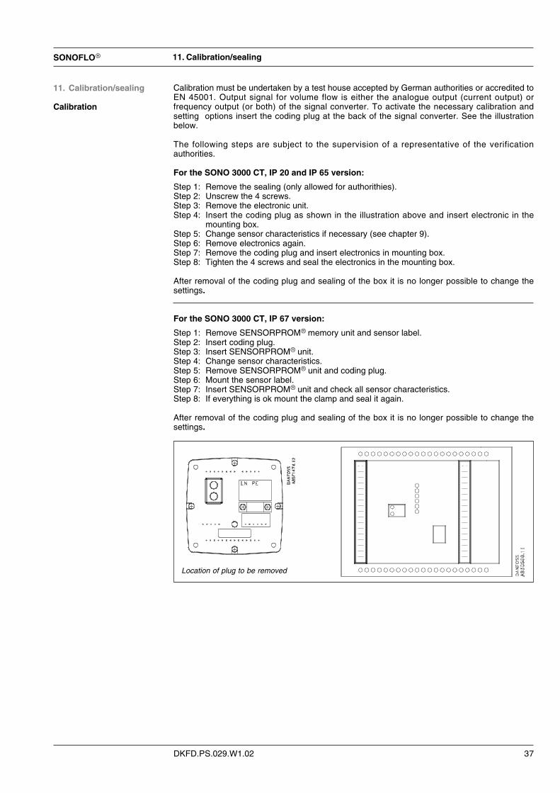
Calibration must be undertaken by a test house accepted by German authorities or accredited toEN 45001. Output signal for volume flow is either the analogue output (current output) orfrequency output (or both) of the signal converter. To activate the necessary calibration andsetting options insert the coding plug at the back of the signal converter. See the illustrationbelow.
The following steps are subject to the supervision of a representative of the verificationauthorities.
For the SONO 3000 CT, IP 20 and IP 65 version:
Step 1: Remove the sealing (only allowed for authorithies).Step 2: Unscrew the 4 screws.Step 3: Remove the electronic unit.Step 4: Insert the coding plug as shown in the illustration above and insert electronic in the
mounting box.Step 5: Change sensor characteristics if necessary (see chapter 9).Step 6: Remove electronics again.Step 7: Remove the coding plug and insert electronics in mounting box.Step 8: Tighten the 4 screws and seal the electronics in the mounting box.
After removal of the coding plug and sealing of the box it is no longer possible to change thesettings.
For the SONO 3000 CT, IP 67 version:
Step 1: Remove SENSORPROM� memory unit and sensor label.Step 2: Insert coding plug.Step 3: Insert SENSORPROM� unit.Step 4: Change sensor characteristics.Step 5: Remove SENSORPROM� unit and coding plug.Step 6: Mount the sensor label.Step 7: Insert SENSORPROM� unit and check all sensor characteristics.Step 8: If everything is ok mount the clamp and seal it again.
After removal of the coding plug and sealing of the box it is no longer possible to change thesettings.
11. Calibration/sealing
Calibration
11. Calibration/sealing
Location of plug to be removed

DKFD.PS.029.W1.02
SONOFLO�
38
There are 2 labels for a SONO CT. One for the sensor and one for the signal converter. The datalabel contains data for the SONO 3300/3000 CT. Always check the data on the data label and thedata in the sensor characteristics.Before installation always ensure that the system numbers of the sensor and signal converter areidentical.
The approval mark does depend on the country specification.
Data label
12. Calibration/sealing
SONO CT OIML label
SONO CT PTB label

SONOFLO�
DKFD.PS.029.W1.02 39
The signal converter, SONO 3000 CT, IP 67,has a verification sealing (without stating theyear) at one screw and at the bending for theSENSORPROM� memory unit, see illustra-tion.
All signal converters SONO 3000 CT have averification sealing (stating the year of verifica-tion) on the data label which is mounted on theoutside of the signal converter, see illustration.
For the signal converter, SONO 3000 CT,IP 20 and IP 65, the electronic and enclosureare sealed by verification authorities.
Verification sealing
11. Calibration/sealing
The sensor, SONO 3300 CT, has a verificationsealing (without stating the year of verification)on the data label, which is mounted on thesensor, see illustration.
DKFD.PS.029.W1.02
SONOFLO�
40
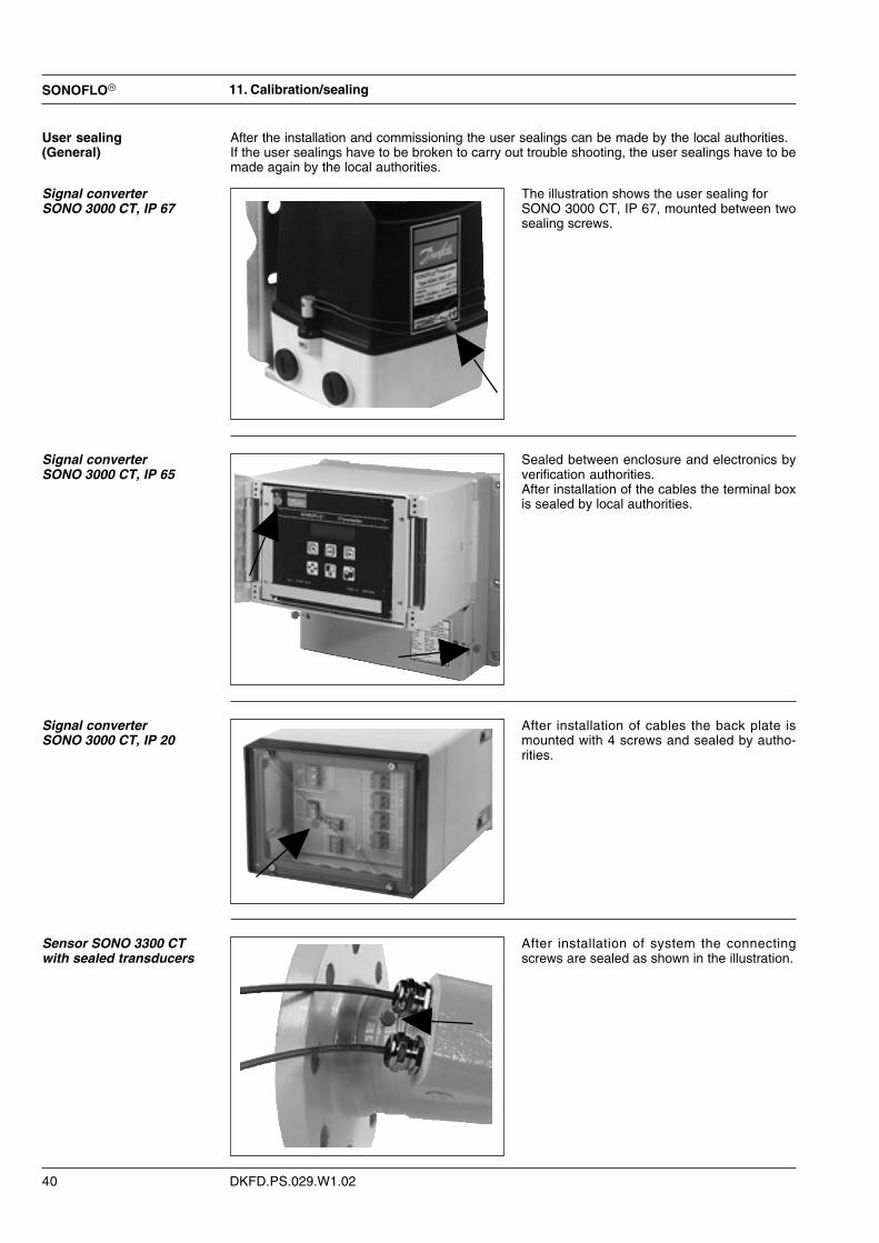
After the installation and commissioning the user sealings can be made by the local authorities.If the user sealings have to be broken to carry out trouble shooting, the user sealings have to bemade again by the local authorities.
The illustration shows the user sealing forSONO 3000 CT, IP 67, mounted between twosealing screws.
Sealed between enclosure and electronics byverification authorities.After installation of the cables the terminal boxis sealed by local authorities.
After installation of cables the back plate ismounted with 4 screws and sealed by autho-rities.
After installation of system the connectingscrews are sealed as shown in the illustration.
User sealing(General)
Signal converterSONO 3000 CT, IP 67
Signal converterSONO 3000 CT, IP 65
Signal converterSONO 3000 CT, IP 20
Sensor SONO 3300 CTwith sealed transducers
11. Calibration/sealing

SONOFLO�
DKFD.PS.029.W1.02 41
Type no. SONO CT - - -
1. SensorSize Flanges PN 10 PN 16 PN 25 PN 40
DN 50 - 09C 09E 09E
DN 65 - 10C 10E 10E
DN 80 - 11C 11E 11E
DN 100 - 12C 12E 12E
DN 125 - 13C 13E 13E
DN 150 - 14C 14E 14E
DN 200 - 15C 15D 15E
DN 250 - 16C 16D 16E
DN 300 - 17C 17D 17E
DN 350 - 18C 18D 18E
DN 400 - 19C 19D 19E
DN 500 20B 20C 20D 20E
DN 600 21B 21C 21D -
DN 700 22B 22C 22D -
DN 800 23B 23C 23D -
DN 900 24B 24C 24D
DN 1000 25B 25C 25D -
DN 1200 27B 27C - -
2. Material certificateWithout certificate (Standard) ...................................................................................... 0DIN 50.049-3.1B material, certificates enclosed ........................................................... 1
3. Signal converter, SONO 3000 CTpower suply
- IP 67, for wall mounting 115-230 V a.c. 50/60 Hz ............................................................ 2
- IP 65, for wall mounting 115/230 V a.c. 50/60 Hz ............................................................ 324 V a.c./d.c. .............................................................................. 4
- IP 20, front of panel 115/230 V a.c. 50/60 Hz ............................................................ 5
4. Cable between sensor and signal converter4 x 10 meter coaxial cable ............................................................................................................... 14 x 20 meter coaxial cable ............................................................................................................... 24 x 30 meter coaxial cable ............................................................................................................... 3
5. Country specificStandard (without verification) ................................................................................................................ ADenmark (OIML R 75) ............................................................................................................................. EGermany (PTB) ....................................................................................................................................... F
For specifiying the flow volume (Qn) and the settings in the converter, fill out extended ordering form on nextpage.
12. Ordering
12. Ordering

DKFD.PS.029.W1.02
SONOFLO�
42
Extended ordering formSettings for SONO 3000 CT. To be filled in for each flowmeter
BASIC SETTINGS Factory setting Options SettingFlow direction Positiv Positiv
Volume flow unit m3/h m3/h
Volume flow nominal DN 50 36 m3/h DN 50 3 - 84 m3/h
DN 65 60 m3/h DN 80 5 - 140 m3/h
DN 80 100 m3/h DN 80 8 - 192 m3/h
DN 100 180 m3/h DN 100 12 - 324 m3/h
DN 125 250 m3/h DN 125 20 - 490 m3/h
DN 150 360 m3/h DN 150 30 - 720 m3/h
DN 200 600 m3/h DN 200 50 - 1.215 m3/h
DN 250 1000 m3/h DN 250 80 - 1.917 m3/h
DN 300 1500 m3/h DN 300 110 - 2.740 m3/h
DN 350 2000 m3/h DN 350 130 - 3.261 m3/h
DN 400 2500 m3/h DN 400 170 - 4.309 m3/h
DN 500 3000 m3/h DN 500 280 - 7.069 m3/h
DN 600 3500 m3/h DN 600 400 - 9.923 m3/h
DN 700 4000 m3/h DN 700 550 - 13.854 m3/h
DN 800 4500 m3/h DN 800 720 - 18.096 m3/h
DN 900 5000 m3/h DN 900 920 - 22.902 m3/h
DN 1000 5000 m3/h DN 1000 1.130 - 28.274 m3/h
DN 1200 6000 m3/h DN 1200 1.630 - 40.715 m3/h
OUTPUT SETTINGSOutput Volume flow Volume flow, OFF
Current direction Unidirectional Unidirectional, bidirectional
Current output range 4…20 mA 0…20 mA, 4…20 mA
Current output time constant 5 s 0.8…30 s
Frequency pulse Volume flow Volume flow, OFF
Frequency / pulse / direction Unidirectional Unidirectional, bidirectional
Frequency / pulse Pulse Pulse, frequency
Pulse unit m3 m3, L
Pulse volume / pulse (DN 50-150) = 0.1 m3/pulse 0.1 … 1000
(DN 200-600) = 1 m3/pulse 0.1 … 1000
(DN 700-1200) = 10 m3/pulse 0.1 … 1000
Pulse pulse width 5 ms 20 ms, 0.5 ms, 50 ms, 100 ms
Frequency max. frequency 10 kHz 1 kHz, 10 kHz
Frequency time constant 5 s 0.8…30 s
Relay Error function Error function, flow direction, OFF
APPLICATIONPARAMETERSStandard cable length As specified page 41 4 x 10 m, 4 x 20 m, 4 x 30 m
Extra cable Up to 250 meter cable depending onapproval.Specify length that will be added to the 4x__________mabove length on each transducer
Language English English, German
The flowmeter will be delivered with the standard factory settings if this form is not filled in.
If the nominal volume flow , which is to be set, differs from the factory setting and the flowmeter is to be verified in accordance withMDIR 27.01-01 or TR K7, the flow values have to be within the limits stated in chapter 6.
12. Ordering
Flow
rate
is d
epen
ding
on
appr
oval
- this page has been updated 2002.05.17

SONOFLO�
DKFD.PS.029.W1.02 43
Accessories Type / description Code no.SONO 3000 CT signal converter, IP 67 (incl. wall mounting kit)* 085F5004
SONO 3000 CT signal converter, IP 65,115/230 V a.c. / 50 - 60 Hz* 085F5023
SONO 3000 CT signal converter, IP 65,24 V a.c. / d.c.* 085F5024
SONO 3000 CT signal converter, IP 20* 085F5019
1 x10 meter coax cable with transducer connection 085L2400
1 x 20 meter coax cable with transducer connection 085L2401
1 x 30 meter coax cable with transducer connection 085L2402
12. Ordering
* All 4 converters have 1 current output, 1 frq / pulse output and 1 relay each.

DKFD.PS.029.W1.02521H0721 ��Danfoss A/S (FD-SF/AN&SSS) 05/2002 / P70
The Danfoss A/S, Flow Division range contains:
MAGFLO� electromagnetic flowmetersMAGFLO� flowmeters are used for all electrically conductiveliquids.A wide range is offered for:� The water treatment sector – enclosures are IP 67 as
standard.� The chemical industry – Ex-approved and other versions
available.� The food industry – stainless steel and other versions
available.
SONOFLO� ultrasonic flowmetersSONOFLO� flowmeters measure flow in full pipes.SONOFLO� flowmeters measure media in liquid form, irrespec-tive of electrical conductivity.The range includes a one- to four-track flowmeter, SONO 3000.The meter is also available in a compact Ex-version.SONOFLO� flowmeters can also be installed on existing pipes,providing low cost installations, especially where large pipes areconcerned.
MASSFLO� mass flowmetersMASSFLO� flowmeters measure flow direct in kg/h. In addition,MASSFLO� flowmeters measure:� Density� Temperature� Sugar concentration i.e. �BrixMASSFLO� flowmeters are available in stainless steel,Hastelloy and with integrated heating.MASSFLO� flowmeters can be obtained in an intrinsically safeversion for explosive areas.
MASSFLO�, MAGFLO�, SONOFLO�, SONOCAL�� and SENSORPROM� are registered Danfoss trademarks.
SONOCAL� ultrasonic heat meterSONOCAL� serie 3000 ultrasonic heat meter.


![Ultrasonic flowmeter for use with transmitter type FUS060 · for use with transmitter type FUS060 [] ... SITRANS F US ultrasonic flowmeter sensor type SONO 3300 2-track with transmitter](https://static.fdocuments.net/doc/165x107/5ae2ce877f8b9ae74a8cec2e/ultrasonic-flowmeter-for-use-with-transmitter-type-use-with-transmitter-type-fus060.jpg)
