
ULTRASONIC EAVESDROPPER - uCozsirak.ucoz.ru/_ld/2/280_TVM.pdfULTRASONIC EAVESDROPPER ... In the...
11
Constructional Project 18 Everyday Practical Electronics, September 2008 ULTRASONIC EAVESDROPPER Ever wanted to be able to listen to the ‘unlistenable’ – sounds that are way beyond the range of normal human hearing? Like the super- sonic whine of a gas leak, or the echo-location ‘chirps’ of bats? Here’s a low-cost project that will let you do just that. It’s a down-converter, which shifts ultrasonic sound signals down into the frequency range where they can be heard (or recorded). A FEW WEEKS AGO, I found myself watching a wild- life documentary on TV in which naturalists were studying the behaviour of bats. They were using infrared lighting to photograph them and a down-converter so that they could hear and record the ultrasonic ‘chirps’ that the bats use for navigation in the dark – and often for tracking down their insect prey/food. My curiosity was aroused and I decided to ‘have a go’ at coming up with a low-cost down-converter of my own. This project is the end result, presented so that readers can also indulge their curiosity. I won’t claim that the project has all kinds of uses, because it’s mainly going to be useful for listening to the ultrasonic sounds emitted by bats and one or two other nocturnal insect-eating creatures. But you should also be able to use it to track down the exact location of high-pressure gas leaks – which appar- ently also produce an ultrasonic whistle or whine. You could even use it to make sure an ultrasonic dog whistle is working. If Fido seems to be ignoring it perhaps his hearing has deteriorated like mine! How it works Most of the sounds emitted by bats are in the frequency range from about 15kHz to 50kHz, with a few extending up to about 150kHz and a small number extending down below 10kHz. So most of them are above the range of hu- man hearing, and some well above. (Young people can often hear up to about 18-20kHz, but this upper limit generally falls as we grow older.) The idea of the eavesdropper is to shift the ultrasonic sounds down in frequency, so they fall within our comfort- able hearing range. This is done by using the heterodyne principle, in much the same way as it’s used in many radio receivers. Or more accurately, in exactly the same way as it’s used in ‘direct conversion’ receivers: we mix the incoming ultrasonic signals with a continuous ultrasonic signal from a ‘local oscillator’. In the mixer, the two signals heterodyne or ‘beat’ together, generating signals which correspond to the sum and dif- ference of the two frequencies. The ‘sum’ signal will be very high in the ultrasonic range – and thus even more inaudible – but the ‘difference’ signal is easily arranged to be much lower in frequency and therefore in the audible (to humans!) range. You can see how this down-conversion system works from the block diagram in Fig.1. The ultra- sonic sounds are picked up by a small electret mi- crophone, which turns them into small ultrasonic electrical signals. This type of microphone has a frequency by Jim Rowe
Transcript of ULTRASONIC EAVESDROPPER - uCozsirak.ucoz.ru/_ld/2/280_TVM.pdfULTRASONIC EAVESDROPPER ... In the...

Constructional Project Constructional Project
18 Everyday Practical Electronics, September 2008
Constructional Project Constructional Project
ULTRASONICEAVESDROPPER
Ever wanted to be able to listen to the ‘unlistenable’ – sounds that are way beyond the range of normal human hearing? Like the super-sonic whine of a gas leak, or the echo-location ‘chirps’ of bats? Here’s a low-cost project that will let you do just that. It’s a down-converter, which shifts ultrasonic sound signals down into the frequency range where they can be heard (or recorded).
A FEW WEEKS AGO, I found myself watching a wild-life documentary on TV in which naturalists were studying the behaviour of bats. They were using
infrared lighting to photograph them and a down-converter so that they could hear and record the ultrasonic ‘chirps’ that the bats use for navigation in the dark – and often for tracking down their insect prey/food.
My curiosity was aroused and I decided to ‘have a go’ at coming up with a low-cost down-converter of my own. This project is the end result, presented so that readers can also indulge their curiosity.
I won’t claim that the project has all kinds of uses, because it’s mainly going to be useful for listening to the ultrasonic sounds emitted by bats and one or two other nocturnal insect-eating creatures.
But you should also be able to use it to track down the exact location of high-pressure gas leaks – which appar-ently also produce an ultrasonic whistle or whine. You could even use it to make sure an ultrasonic dog whistle is working. If Fido seems to be ignoring it perhaps his hearing has deteriorated like mine!
How it worksMost of the sounds emitted by bats are in the frequency
range from about 15kHz to 50kHz, with a few extending
up to about 150kHz and a small number extending down below 10kHz. So most of them are above the range of hu-man hearing, and some well above. (Young people can often hear up to about 18-20kHz, but this upper limit generally falls as we grow older.)
The idea of the eavesdropper is to shift the ultrasonic sounds down in frequency, so they fall within our comfort-able hearing range.
This is done by using the heterodyne principle, in much the same way as it’s used in many radio receivers. Or more accurately, in exactly the same way as it’s used in ‘direct conversion’ receivers: we mix the incoming ultrasonic signals with a continuous ultrasonic signal from a ‘local oscillator’.
In the mixer, the two signals heterodyne or ‘beat’ together, generating signals which correspond to the sum and dif-ference of the two frequencies. The ‘sum’ signal will be very high in the ultrasonic range – and thus even more inaudible – but the ‘difference’ signal is easily arranged to be much lower in frequency and therefore in the audible (to humans!) range.
You can see how this down-conversion system works from the block diagram in Fig.1. The ultra-sonic sounds are picked up by a small electret mi-crophone, which turns them into small ultrasonic electrical signals. This type of microphone has a frequency
by Jim Rowe

Constructional Project Constructional Project Constructional Project Constructional Project
Everyday Practical Electronics, September 2008 19
ULTRASONICEAVESDROPPER
response which extends well up into the ultrasonic region.
The signals are then passed through a preamplifi er to boost them to a more useful amplitude (or level), where they can be passed into one input of a balanced mixer. The other input to the mixer is fed with a continuous ultrasonic signal produced by a tuneable ‘local oscilla-tor’, so it can be varied in frequency from about 15kHz to 50kHz.
As a result, the output of the balanced mixer contains three main frequency components: the difference signals (FIN – FOSC) and (FOSC – FIN), and the sum signal (FIN + FOSC). The sum signal is obviously even higher in the ultrasonic range than FIN and FOSC, so it’s of no interest to us. We fi lter it out, anyway. But by adjusting the tuning of the local oscillator the difference signals can be placed down in the audible range, so all we have to do is feed them through an audio amplifi er (via a volume control),
so that they can be either heard though a pair of headphones or sent to a tape or other recorder (even recorded on a computer hard disk or memory card for later analysis).
What’s with the dish?Used by itself, the electret micro-
phone insert works – but not very well. To make it more effective, we concen-trate the ultrasonic sound waves with a small, ‘somewhat’ parabolic dish.
As you may recall from previous projects, a parabolic dish refl ects all the waves which strike it to its focal point. With the microphone insert mounted
Fig.1: this block diagram shows the various functional elements of the Ultrasonic Eavesdropper.

Constructional Project Constructional Project
20 EverydayPracticalElectronics,September2008
Constructional Project Constructional Project
λ
IC5
LM38
6NIC
5LM
386N
1
23
4
5
6
78
IC2
4017
BIC
240
17B
MR Vs
sVdd
CP0
CP1
O0
O1
O2
O3
O4
O5
O6
O7
O8
O9
O5-
9
1 2 3456 7
8
9 1011
12
1314 15
16
IC4
MC
1496
IC4
MC
1496
IC1a
IC1b
IC1c
IC1d
IC1:
409
3B
IC3a
IC3a
IC3b
IC3b
IC3:
LM
833
47Fµ
4.7k
180k
220k
470Ω
220k
VR2
5k470n
F
6.8k
+12V 1k
22Fµ
1k470Ω
470Ω
100n
F
100n
F
VR4
1k
4.7n
F10
0nF
4.7n
F1k
2.2
Fµ
4.7n
F
100n
F
1.5k
10k
2x 3.3k
4.7n
F68
0Ω100n
F
+12V
100
Fµ
100n
F1n
F1.2k
VR1
5k
OSC
ILLAT
OR
FREQ
UEN
CY
30k
30k
120k
120k
16k
11k
16k
11k
10k
220Ω
LED
1
1k
2200
Fµ
D1
1N40
04
12-1
5VD
CIN
PUT
220
Fµ
1k
10Ω
47nF
10Fµ
VR3
10k
10nF
MIC
1EL
ECTR
ETIN
SERT
+
PREA
MP
GA
IN
560Ω
MIX
ERBA
LAN
CE
STER
EOPH
ON
ES
REC
ORD
OU
T
VOLU
ME
123
45
6810
12
14
123
456
78
2006SC
ULTR
ASON
IC E
AVES
DROP
PER
220
Fµ
100ΩZD
112
V1W
100Ω
AK
A K
AK
12
3
4
56
7
8 9
1011
12 13
14
KA
AK
LED
AK
ZD1
1N40
04CO
N3 CO
N2
CO
N4
CO
N1
MIC
INPU
T
Fig
.2: t
he
circ
uit
bea
ts t
he
‘bat
’ fre
quen
cy a
gain
st t
he
sup
erso
nic
gen
erat
or f
orm
ed b
y IC
1 an
d I
C2.
λ
IC5
LM38
6NIC
5LM
386N
1
23
4
5
6
78
IC2
4017
BIC
240
17B
MR Vs
sVdd
CP0
CP1
O0
O1
O2
O3
O4
O5
O6
O7
O8
O9
O5-
9
1 2 3456 7
8
9 1011
12
1314 15
16
IC4
MC
1496
IC4
MC
1496
IC1a
IC1b
IC1c
IC1d
IC1:
409
3B
IC3a
IC3a
IC3b
IC3b
IC3:
LM
833
47Fµ
4.7k
180k
220k
470Ω
220k
VR2
5k470n
F
6.8k
+12V 1k
22Fµ
1k470Ω
470Ω
100n
F
100n
F
VR4
1k
4.7n
F10
0nF
4.7n
F1k
2.2
Fµ
4.7n
F
100n
F
1.5k
10k
2x 3.3k
4.7n
F68
0Ω100n
F
+12V
100
Fµ
100n
F1n
F1.2k
VR1
5k
OSC
ILLAT
OR
FREQ
UEN
CY
30k
30k
120k
120k
16k
11k
16k
11k
10k
220Ω
LED
1
1k
2200
Fµ
D1
1N40
04
12-1
5VD
CIN
PUT
220
Fµ
1k
10Ω
47nF
10Fµ
VR3
10k
10nF
MIC
1EL
ECTR
ETIN
SERT
+
PREA
MP
GA
IN
560Ω
MIX
ERBA
LAN
CE
STER
EOPH
ON
ES
REC
ORD
OU
T
VOLU
ME
123
45
6810
12
14
123
456
78
2006SC
ULTR
ASON
IC E
AVES
DROP
PER
220
Fµ
100ΩZD
112
V1W
100Ω
AK
A K
AK
12
3
4
56
7
8 9
1011
12 13
14
KA
AK
LED
AK
ZD1
1N40
04CO
N3 CO
N2
CO
N4
CO
N1
MIC
INPU
T

Constructional Project Constructional Project Constructional Project Constructional Project
Everyday Practical Electronics, September 2008 21
at the focal point (or as close as we can guess!), pick-up becomes much more efficient and effective.
This dish can be made from just about any material which will reflect sound waves – we used a laminated wood cereal or salad bowl, bought from a ‘bargain store’ for just a couple of pounds. It is about 155mm in diam-eter and about 39mm deep, but this is not at all critical – a larger dish should be even better, but would start to become unwieldy.
A similar (hard) plastic or even stainless steel salad bowl could also be used.
We said a moment ago that it was ‘somewhat’ parabolic in shape – it has a flat bottom. This might not be technically ideal but it is good enough for our purposes – and certainly makes it a lot simpler to attach things to!
You can work out the focal point of a parabola by formula (but it is complicated by the flat bottom), or you could line the bowl with aluminium foil and aim the bowl at the sun to enable you to get it spot on.
Another way of finding the focal point would be to con-nect the mic insert to an audio amplifier and aim the dish at a single point sound source (such as a speaker connected to an oscillator). Moving the microphone back and forward
along the centre axis would reveal one point where the maximum signal was found.
Having said all that, we found near enough (an educated guess) was good enough – but feel free to experiment with distances! We’ll look at mounting the dish and microphone a little later.
The circuitNow let’s look at the circuit diagram (Fig.2) for a more
detailed understanding of how it works. The ultrasonic sounds are picked up by the electret microphone insert, MIC1.
The fairly small signals from MIC1 are fed in via CON1 and first amplified by IC3a, half of an LM833 dual low-noise op amp. It’s used here as a preamp with its gain variable between about 40 and 400, using trimpot VR2.
This allows the project to be set up for either short or long range bat monitoring, and with bats having either loud or soft ‘chirping’ (they do vary between species).
After amplification, the signals are passed through IC3b, the ‘other half’ of the LM833, connected as a unity-gain buffer to provide a low impedance source feeding the mixer IC4, via a 1kW series resistor.
Fig.3: the entire project mounts on a single PC board, with the electret mic insert connected via an RCA phono socket on the left side. The sockets on the right connect power (12V DC), earphones and some form of audio recorder.

Constructional Project Constructional Project
22 EverydayPracticalElectronics,September2008
Constructional Project Constructional Project
The completed PC board screwed to the lid of the UB3-type box, which becomes the base. Actually, this photo is a tad premature in the assembly sequence because you need to screw the lid to the timberwork, then fit the PC board to the lid.
Here you can see how the plastic case needs to be drilled and slotted...
...so that the PC board is an easy fit.
Again, the lid is screwed to the handle before the board is
placed inside the box.
Local oscillatorThe ultrasonic signal used for our ‘local oscillator’ is
generated using IC1 and IC2. This signal (a) needs to be tuneable over a fairly wide frequency range; (b) should be reasonably low in harmonic content and (c) should also be fairly constant in amplitude. However, this combination of qualities is not easy to produce using conventional audio oscillator circuits.
So we generate it in a slightly unusual fashion. Gates IC1a, IC1b and IC1d are used as a relaxation-type oscillator, producing a square wave clock signal which is variable be-tween 150kHz and 500kHz using potentiometer VR1. This clock signal is buffered by gate IC1c and fed into the clock input of IC2, a 4017B Johnson-type decade counter.
This IC therefore counts the clock signals so that its 10 outputs, O0 to O9, switch high in turn, on a continuous cyclic basis. These outputs are used to drive a simple dig-ital-to-analogue converter (DAC) using a set of resistors. While it may appear that output O7 is not used, it is – its ‘infinite value’ resistor (ie, open circuit) actually sets the zero point.
The values of the resistors are carefully chosen so that as the outputs of IC2 go high in turn, a 10-sample ap-proximation of a sinewave is developed across the output (ie, the 680W resistor between pins 10 and 8 of IC4). The 4.7nF capacitor which is also across the output provides a measure of low-pass filtering and further ‘smoothing’ of the sinewave.
The result of this simple digital waveform synthesis is a fairly smooth sinewave signal of reason-ably constant amplitude, with a frequency exactly one tenth that of the clock signal from IC1. So as the clock signal is varied between 150 and 500kHz via VR1, the ‘local oscillator’ sinewave signal at the pin 10 input of IC4 is varied between 15kHz and 50kHz.
Balanced mixerIC4 is an MC1496 double-balanced mixer, expressly
designed for this kind of use. When we feed our ampli-fied ultrasonic sound input signal into pin 1 and our local oscillator signal into pin 10, it performs an analogue mul-tiplication between them and provides the corresponding sum and difference frequency signals at its outputs (pins 6 and 12, which are simply dual polarity outputs).
By the way, the mixer strictly only produces just the sum and difference signals at its outputs when it is carefully balanced using trimpot VR4. If it is not truly balanced, both of the input signals can also be present in the outputs – although this is not a major problem here because both of these input signals are inaudible.
All the same, it’s a good idea to have the mixer reason-ably close to balance, to reduce distortion

Constructional Project Constructional Project Constructional Project Constructional Project
Everyday Practical Electronics, September 2008 23
Fig.4: use this diagram in conjunction with the photo above to work out which bit goes where!
The ‘gun’ assembly immediately before the case lid is secured. You can clearly see how the piece of coat hanger wire, which supports the electret microphone, is attached.
in the audio amplifier. We’ll explain how to do this later.
As you can see, in this project we take the mixer output signal from pin 6 of IC4 and then pass it through a simple low-pass filter using the 1kW series resistor and 4.7nF capacitor (across volume control VR3). This filtering attenu-ates the ‘sum’ frequency components quite significantly, leaving mainly just the audi-ble ‘difference’ components that represent the downshifted version of our ultrasonic sound signals. We then pass these through audio amplifier IC5, after adjusting their volume level via potentiometer VR3.
The amplified output of IC5 is used to drive a standard pair of stereo headphones via CON4 and/or an audio recorder via line-level output CON2.
The complete circuit is designed to operate from almost any source of 12V to 15V DC, which is fed in via CON3 and can come from either a small AC plugpack supply or a nominal 12V battery, such as that in a car or motorcycle.
The total current drain is less than 35mA, so you could also run it from a pair of 6V lantern batteries connected in series, or even a pack of eight C-cells. Zener diode ZD1 limits the voltage which can be fed to ICs 1 to 3, while LED1 indicates that power is applied.
ConstructionAll of the Eavesdropper circuitry is mounted on a single PC
board, measuring only 122 × 57mm. This board is available from the EPE PCB Service, code 683. The component layout is shown in Fig.3. As you can see, the board has rounded cutouts at each corner so that it can be mounted snugly inside a standard plastic box measuring 130 × 68 × 44mm.
Microphone input socket CON1 is mounted on the left-hand end of the board, while the DC input, headphone output and recording output connectors are all mounted on the right-hand end. The local oscillator ‘tuning’ pot VR1, power LED1 and volume control pot VR3 are all mounted along the front side for easy access.
Begin construction by checking the PC board for any etching problems or undrilled holes and fixing these before
you proceed. Then it’s a good idea to fit the various connec-tors (CON1 to CON4), as these sometimes require a small amount of fiddling and board hole enlargement.
There is only one wire link to be fitted to the board, so it’s suggested you fit this next to make sure it isn’t forgotten. It’s located just behind CON4 at lower right, as viewed in the PC board overlay diagram.
Next, fit the various fixed resistors, taking care to fit each one in its correct position. These can be followed by trimpots VR2 and VR4, making sure you don’t swap them around. The 5kW trimpot is VR2, while the 1kW trimpot is VR4. Don’t fit the two large rotary pots at this stage – they’re best fitted later.
Now you can fit the capacitors, starting with the two 100nF multilayer monolithics (near IC1 and IC2) and then progressing through the small MKT caps, the 2.2mF tag tantalum electrolytic (just to the front of IC5) and then the other electrolytics. Remember that all the electrolytics are polarised, so make sure you orient them correctly (as shown in Fig.3, the PC board overlay diagram).
After these you can fit the semiconductors, starting with diode D1 and Zener diode ZD1 – again, make sure you don’t

Constructional Project Constructional Project
24 EverydayPracticalElectronics,September2008
Constructional Project Constructional Project
swap these accidentally and that they are both fitted with the correct orientation, as shown in the overlay diagram and photos. Then fit the ICs, preferably in reverse numbered order (ie, IC5 first, then IC4, working your way back to IC2 and IC1). Although there is no need to fit any of the ICs in sockets, we suggest that you do. All five ICs must be oriented as shown.
If you are soldering IC2 and IC1 directly into the board, take extra care to protect them from the possibility of electrostatic damage. Use an earthed soldering iron, earth yourself if possible (or at least discharge yourself before handling the ICs) and solder the supply pins of the ICs first (pins 7 and 14 on IC1, pins 8 and 16 on IC2) to enable their internal protection circuitry as early as possible.
After the ICs are in position, it’s time to fit power LED1. This is fitted to the board vertically to begin with, with its longer anode (A) lead to the right and both leads soldered to their pads underneath with the LED’s body about 18mm above the board. Then, using a pair of needle-nose pliers or similar, bend both leads forward by 90°, 12mm above the board. This will position the LED facing forward and ready to protrude through the matching hole in the box, after final assembly.
The last two components to mount on the board are control pots VR1 and VR3, which are both fitted along the front of the board on either side of LED1. You may need to cut the pot spindles to about 10-12mm long before they’re
Fig.5: hole drilling diagram for a UB3-type plastic box.
Constructional Project Constructional Project Constructional Project Constructional Project
Everyday Practical Electronics, September 2008 25
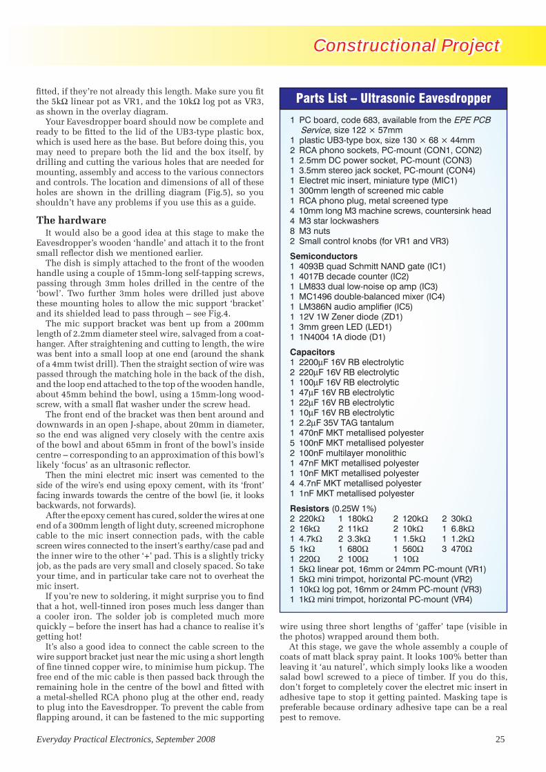
Parts List – Ultrasonic Eavesdropper
1 PC board, code 683, available from the EPE PCB Service, size 122 × 57mm
1 plastic UB3-type box, size 130 × 68 × 44mm 2 RCA phono sockets, PC-mount (CON1, CON2)1 2.5mm DC power socket, PC-mount (CON3)1 3.5mm stereo jack socket, PC-mount (CON4)1 Electret mic insert, miniature type (MIC1)1 300mm length of screened mic cable1 RCA phono plug, metal screened type4 10mm long M3 machine screws, countersink head4 M3 star lockwashers8 M3 nuts2 Small control knobs (for VR1 and VR3)
Semiconductors1 4093B quad Schmitt NAND gate (IC1)1 4017B decade counter (IC2)1 LM833 dual low-noise op amp (IC3)1 MC1496 double-balanced mixer (IC4)1 LM386N audio amplifier (IC5)1 12V 1W Zener diode (ZD1)1 3mm green LED (LED1)1 1N4004 1A diode (D1)
Capacitors1 2200mF 16V RB electrolytic2 220mF 16V RB electrolytic1 100mF 16V RB electrolytic1 47mF 16V RB electrolytic1 22mF 16V RB electrolytic1 10mF 16V RB electrolytic1 2.2mF 35V TAG tantalum1 470nF MKT metallised polyester5 100nF MKT metallised polyester2 100nF multilayer monolithic1 47nF MKT metallised polyester1 10nF MKT metallised polyester4 4.7nF MKT metallised polyester1 1nF MKT metallised polyester
Resistors (0.25W 1%)2 220kW 1 180kW 2 120kW 2 30kW2 16kW 2 11kW 2 10kW 1 6.8kW1 4.7kW 2 3.3kW 1 1.5kW 1 1.2kW5 1kW 1 680W 1 560W 3 470W1 220W 2 100W 1 10W1 5kW linear pot, 16mm or 24mm PC-mount (VR1)1 5kW mini trimpot, horizontal PC-mount (VR2)1 10kW log pot, 16mm or 24mm PC-mount (VR3)1 1kW mini trimpot, horizontal PC-mount (VR4)
fitted, if they’re not already this length. Make sure you fit the 5kW linear pot as VR1, and the 10kW log pot as VR3, as shown in the overlay diagram.
Your Eavesdropper board should now be complete and ready to be fitted to the lid of the UB3-type plastic box, which is used here as the base. But before doing this, you may need to prepare both the lid and the box itself, by drilling and cutting the various holes that are needed for mounting, assembly and access to the various connectors and controls. The location and dimensions of all of these holes are shown in the drilling diagram (Fig.5), so you shouldn’t have any problems if you use this as a guide.
The hardwareIt would also be a good idea at this stage to make the
Eavesdropper’s wooden ‘handle’ and attach it to the front small reflector dish we mentioned earlier.
The dish is simply attached to the front of the wooden handle using a couple of 15mm-long self-tapping screws, passing through 3mm holes drilled in the centre of the ‘bowl’. Two further 3mm holes were drilled just above these mounting holes to allow the mic support ‘bracket’ and its shielded lead to pass through – see Fig.4.
The mic support bracket was bent up from a 200mm length of 2.2mm diameter steel wire, salvaged from a coat- hanger. After straightening and cutting to length, the wire was bent into a small loop at one end (around the shank of a 4mm twist drill). Then the straight section of wire was passed through the matching hole in the back of the dish, and the loop end attached to the top of the wooden handle, about 45mm behind the bowl, using a 15mm-long wood-screw, with a small flat washer under the screw head.
The front end of the bracket was then bent around and downwards in an open J-shape, about 20mm in diameter, so the end was aligned very closely with the centre axis of the bowl and about 65mm in front of the bowl’s inside centre – corresponding to an approximation of this bowl’s likely ‘focus’ as an ultrasonic reflector.
Then the mini electret mic insert was cemented to the side of the wire’s end using epoxy cement, with its ‘front’ facing inwards towards the centre of the bowl (ie, it looks backwards, not forwards).
After the epoxy cement has cured, solder the wires at one end of a 300mm length of light duty, screened microphone cable to the mic insert connection pads, with the cable screen wires connected to the insert’s earthy/case pad and the inner wire to the other ‘+’ pad. This is a slightly tricky job, as the pads are very small and closely spaced. So take your time, and in particular take care not to overheat the mic insert.
If you’re new to soldering, it might surprise you to find that a hot, well-tinned iron poses much less danger than a cooler iron. The solder job is completed much more quickly – before the insert has had a chance to realise it’s getting hot!
It’s also a good idea to connect the cable screen to the wire support bracket just near the mic using a short length of fine tinned copper wire, to minimise hum pickup. The free end of the mic cable is then passed back through the remaining hole in the centre of the bowl and fitted with a metal-shelled RCA phono plug at the other end, ready to plug into the Eavesdropper. To prevent the cable from flapping around, it can be fastened to the mic supporting
wire using three short lengths of ‘gaffer’ tape (visible in the photos) wrapped around them both.
At this stage, we gave the whole assembly a couple of coats of matt black spray paint. It looks 100% better than leaving it ‘au naturel’, which simply looks like a wooden salad bowl screwed to a piece of timber. If you do this, don’t forget to completely cover the electret mic insert in adhesive tape to stop it getting painted. Masking tape is preferable because ordinary adhesive tape can be a real pest to remove.

Constructional Project Constructional Project
26 EverydayPracticalElectronics,September2008
Constructional Project Constructional Project
Resistor Colour Codes
o No. Value 4-Band Code (1%) 5-Band Code (1%) o 2 220kW red red yellow brown red red black orange brown o 1 180kW brown grey yellow brown brown grey black orange brown o 2 120kW brown red yellow brown brown red black orange brown o 2 30kW orange black orange brown orange black black red brown o 2 16kW brown blue orange brown brown blue black red brown o 2 11kW brown brown orange brown brown brown black red brown o 2 10kW brown black orange brown brown black black red brown o 1 6.8kW blue grey red brown blue grey black brown brown o 1 4.7kW yellow purple red brown yellow purple black brown brown o 1 3.3kW orange orange red brown orange orange black brown brown o 1 1.5kW brown green red brown brown green black brown brown o 1 1.2kW brown red red brown brown red black brown brown o 5 1kW brown black red brown brown black black brown brown o 1 680W blue grey brown brown blue grey black black brown o 1 560W green blue brown brown green blue black black brown o 3 470W yellow purple brown brown yellow purple black black brown o 1 220W red red brown brown red red black black brown o 2 100W brown black brown brown brown black black black brown o 1 10W brown black black gold brown black black gold brown
Once the handle-dish-mic assembly is complete, you can attach the Eaves-dropper’s lid/base plate to the top rear of the wooden handle using a couple of 15mm-long woodscrews through the two 3mm holes in the centre. As you can see, the lid is orientated at right angles to the handle axis, and centred over it.
With the box lid attached to the handle, you can fit the Eavesdrop-per’s finished PC board assembly on to the lid.
It’s attached using four 10mm-long M3 machine screws with countersink heads, passed up from below, and each then fitted with a star lockwasher and M3 nut. These nuts act as spacers, so the screws and nuts should be firmly tightened before the board assembly is fitted. Then, when it is in position, four further nuts are used to hold it in place.
Checkout and adjustmentWhen the PC board assembly is fixed
in place, it’s time to fire up the Eaves-dropper and give it a quick functional checkout.
Set both of the main control pots to roughly their midrange positions, and also set both trimpots to their midrange positions using a small screwdriver or alignment tool. Plug the mic cable into CON1, a pair of standard stereo
Fig.6 (above): the same-size PC board pattern, while below (Fig 7) is a same-size front panel artwork. We simply laminated and glued the paper label to the box, leaving a 2mm border around the edge.
683

Constructional Project Constructional Project Constructional Project Constructional Project
Everyday Practical Electronics, September 2008 27
headphones into CON4 (but don’t put them on yet, just in case something is wrong!) and the cable from your 12V battery or plugpack into CON3.
Power LED1 should immediately light up, to show that the circuit is operating. If the LED doesn’t light, this will probably be because one of three components is fitted to the board with reversed polarity: LED1 itself, D1 or ZD1. Either that or the plug on your DC input cable is wired with reversed polarity.
With a multimeter, check the voltage between the anode of diode D1 and the board’s ground – it should be the same
Capacitor Codes
Value μF Code EIA Code IEC Code 470nF 0.47μF 474 470n 100nF 0.1μF 104 100n 47nF .047μF 473 47n 10nF .01μF 103 10n 4.7nF .0047μF472 4n7 1nF .001μF 102 1n0
as the incoming DC. Similarly, the volt-age at the cathode of D1 should be only 0.6V lower, while that at the cathode end of Zener diode ZD1 should be a little lower again.
You should also be able to measure the same voltage at pin 14 of IC1, pin 16 of IC2 and pin 8 of IC3. Likewise, at pin 6 of IC5 you should find the same voltage as you measured at the cathode of diode D1.
Listen to the headphones without actually putting them on. If they are not shrieking, place the headphones on your ears and you should hear a small amount of noise and/or hum. If you turn up volume control VR3, this noise should increase a little, showing that the audio section of the circuit is working correctly.
Now try returning VR3 to its mid-range position and adjusting ‘tuning’ control VR1 up or down. You may hear a faint heterodyne ‘whistle’ as you tune through one position in the tuning range. This is probably due to the mic preamp picking up a small amount of RF from a local AM radio
Two views looking for’ard and aft. If you paint the whole shebang black, like we did, make sure you wrap a piece of masking tape around the microphone insert first. They don’t like being covered in paint!
station, which then heterodynes with the Eavesdropper’s local oscil-lator or one of its harmonics. This is not likely to interfere with the Eavesdropper’s normal operation, but if nothing else it shows that the Eavesdropper’s local oscillator, ul-trasonic preamp and mixer sections are all working.
If all seems well at this stage, your Eavesdropper is probably working correctly and all that remains to be done before final box assembly is to set the mixer ‘balance’ trimpot VR4 to the correct position.
Got a ’scope?Mixer balance adjustment is easiest
with an oscilloscope, but if you don’t have access to one, you don’t really have to concern yourself about it; simply leave VR4 set to its midrange position, which is very likely to be ‘near enough’ for most purposes.
If you do have access to a scope and you want to set the mixer for the best possible performance, the adjustment is quite easy.

Constructional Project Constructional Project
28 EverydayPracticalElectronics,September2008
All you need to do is monitor the level of the Eavesdropper’s ‘local oscil-lator’ signal appearing at pin 6 of IC4 with your ’scope, while adjusting VR4 with a small screwdriver, or plastic trimming tool. At either end of the trimpot’s range the signal will increase in level, while it will pass through a minimum or ‘null’ somewhere near the middle of the range.
The correct setting for VR4 is right at the centre of this null – this corre-sponds to the mixer being balanced.
Final assemblyThe final assembly step is to fit the
box itself down over the PC board as-sembly, as a protective cover.
This is done by inverting the box and tilting it an angle of about 45° so that it can be offered up to the PC board with the control pot spindles and LED1 entering their matching holes on the box ‘front side’ from the inside.
Then the box is moved towards the mic and reflector bowl, gradually
Here’s what the finished, ready-to-use project looks like – all you need is a 12V battery pack. The headphones can be just about anything – including the bargain shop £1 cheapies!
The top trace of this ’scope shot shows the synthesised sinewave coming from the ladder network of IC2. The lower (blue) trace shows the output at pin 6 of IC4. The very low mean voltage measurement of 5.38mV shows that the modulator is balanced.
tilting it down so that the undrilled long side swings down outside the 220mF electrolytic and the other com-ponents along the rear of the board.
The slots at each end of the box will allow the ends to clear the protrud-ing sleeves of RCA phono connectors CON1 and CON2.
When the box has been juggled into position, it can be attached to the lid/base using the four small self-tapping screws supplied with it. Then the con-trol pots can be fitted with their nuts, which can also be lightly tightened to help support the pots when the Eavesdropper is being used.
After this, you can fit the knobs, and your Eavesdropper should be ready for use.
Using it!Operating the Ultrasonic Eavesdrop-
per is very straightforward. You use ‘tuning’ pot VR1 to search for ultra-sonic sounds over the Eavesdropper’s range and then, when you find one, the same control is used to shift the sounds down to a convenient frequency for listening or recording. Volume control VR3 is used simply to adjust the output audio to a convenient level.
You’ll probably find the Eavesdropper sensitive enough to pick up bat chirps with the preamp gain trimpot VR2 left in its suggested midrange position.
However, if you want to have the highest possible sensitivity, preset VR2 can be turned up to its fully clockwise position.
Happy bat tracking! EPE
Reproduced by arrangement with SILICON CHIP magazine 2008.
www.siliconchip.com.au


