Ultrasonic Controller/Sensor Sensors · Description The Ultrasonic Controller/Sensor has been...
16
MAKING MODERN LIVING POSSIBLE Technical Information Sensors Ultrasonic Controller/Sensor powersolutions.danfoss.com
Transcript of Ultrasonic Controller/Sensor Sensors · Description The Ultrasonic Controller/Sensor has been...
MAKING MODERN LIVING POSSIBLE
Technical Information
SensorsUltrasonic Controller/Sensor
powersolutions.danfoss.com
Revision history Table of revisions
Date Changed Rev
November 2015 Maximum operating temperature 0401
September 2015 Converted to Danfoss layout CA
October 2012 Removed controller 1035027 and 1035039 BA
March 2011 Added PLUS+1® Compliant AB
February 2011 Replaces BLN-95-9078 AA
Technical Information Ultrasonic Controller/Sensor
2 L1009343 • Rev 0401 • November 2015

OverviewDescription..........................................................................................................................................................................................4
1035019, 1035026, 1035029, and 1035036 controllers ................................................................................................41035024 controller .................................................................................................................................................................... 41035022, 1035028, 1035040, and 1035035 sensors ...................................................................................................... 41035023 sensor............................................................................................................................................................................4
Features................................................................................................................................................................................................4Theory of operation.........................................................................................................................................................................4Related product................................................................................................................................................................................ 5
Technical dataSpecifications.....................................................................................................................................................................................6Connector pin definitions..............................................................................................................................................................6Configurations...................................................................................................................................................................................7Dimensions......................................................................................................................................................................................... 8
OperationOperation setup................................................................................................................................................................................ 9Manual functional test (for controllers only).......................................................................................................................... 9
Entering the manual test mode.............................................................................................................................................9Running the five manual tests..................................................................................................................................................... 9
Manual test staging....................................................................................................................................................................9EEPROM memory test................................................................................................................................................................9LED test.........................................................................................................................................................................................10Potentiometer/LED test..........................................................................................................................................................10Ultrasonic transceiver/LED/output driver test .............................................................................................................. 10Exiting manual test mode......................................................................................................................................................10
System diagram1035019, 1035026, 1035029, 1035030, 1035036................................................................................................................121035024, 1035025..........................................................................................................................................................................121035022 open circuit, 1035028 closed circuit, 1035035, 1035040.............................................................................. 13
Control diagram1035019, 1035026..........................................................................................................................................................................141035024, 1035025..........................................................................................................................................................................141035022, 1035028, 1035035, 1035040...................................................................................................................................15
Technical Information Ultrasonic Controller/Sensor
Contents
L1009343 • Rev 0401 • November 2015 3

Description
The Ultrasonic Controller/Sensor has been developed to replace paddle or wand sensors. Both are non-contacting and therefore do not suffer from position or motion problems associated with standardmechanical sensors. These products are typically used to sense and control material flow. All unitsmeasure the distance to a target surface and produce a resulting output.
1035019, 1035026, 1035029, and 1035036 controllers
These controllers generate a signal, that varies proportionally with distance, to control an ElectricalDisplacement Control (EDC) for a hydrostatic transmission. Output from the controller is a pulse-widthmodulated, high-side switched valve drive, with a narrow proportional band. For ease of operation andmounting, the Ultrasonic Controller/Sensor’s sensing distance range can be adjusted by turning anexternal knob mounted on the screed or by activating the dome switches on the devices cover plate.
1035024 controller
This controller drives a solenoid-controlled three-way valve with an output that is either on (full power)when the sensor is far from the target or off (zero power) when the target is near. It’s height is adjustablewith a knob on the screed or by activating the dome switches on the devices cover plate. The 1035025 isidentical to the 5024, except the output is inverted.
1035022, 1035028, 1035040, and 1035035 sensors
These sensors produce an analog voltage output to drive an amplifier for controlling EDCs or bi-directional valves. The output varies proportionally throughout the entire operating range.
1035023 sensor
This sensor produces a PWM output proportional to the distance from the sensor to the target. Anexternal amplifier controls the signal for controlling EDCs or bi-directional valves.
See Technical data on page 6, Connector pin definitions on page 6, and Configurations on page 7.
Features
• Non-contacting sensor
• Easy to mount
• Wide operating range
• Outputs to drive amplifiers or valves directly
• Adjustable setpoint
• On/Off or proportional controller; or ratiometric sensors
Theory of operation
The sensor element of the Ultrasonic Controller/Sensor generates an ultrasonic wave and receives asignal reflected back from the target surface. The time difference between emission and reception isproportional to distance. Sensor products output this distance signal as a voltage to an amplifier, where itis used to control a valve which varies the output speed of a hydrostatic transmission or position of acylinder. See 1035022 open circuit, 1035028 closed circuit, 1035035, 1035040 on page 13.
The controller element of the Ultrasonic Controller/Sensor uses the same sensing head as the sensors,but provides a second control output. See 1035019, 1035026, 1035029, 1035030, 1035036 on page 12.The second output is pulse-width modulated (PWM). For example., a square wave varying from inputvoltage (high) to zero volts (low) whose percentage of time high per cycle varies with measured distance.The PWM output is configured to drive a valve directly. Once the controller is mounted, the desired
Technical Information Ultrasonic Controller/Sensor
Overview
4 L1009343 • Rev 0401 • November 2015
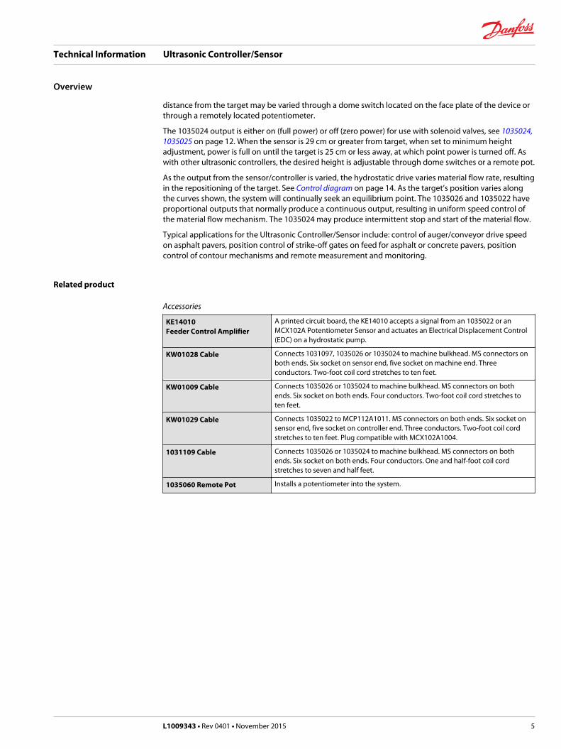
distance from the target may be varied through a dome switch located on the face plate of the device orthrough a remotely located potentiometer.
The 1035024 output is either on (full power) or off (zero power) for use with solenoid valves, see 1035024,1035025 on page 12. When the sensor is 29 cm or greater from target, when set to minimum heightadjustment, power is full on until the target is 25 cm or less away, at which point power is turned off. Aswith other ultrasonic controllers, the desired height is adjustable through dome switches or a remote pot.
As the output from the sensor/controller is varied, the hydrostatic drive varies material flow rate, resultingin the repositioning of the target. See Control diagram on page 14. As the target’s position varies alongthe curves shown, the system will continually seek an equilibrium point. The 1035026 and 1035022 haveproportional outputs that normally produce a continuous output, resulting in uniform speed control ofthe material flow mechanism. The 1035024 may produce intermittent stop and start of the material flow.
Typical applications for the Ultrasonic Controller/Sensor include: control of auger/conveyor drive speedon asphalt pavers, position control of strike-off gates on feed for asphalt or concrete pavers, positioncontrol of contour mechanisms and remote measurement and monitoring.
Related product
Accessories
KE14010Feeder Control Amplifier
A printed circuit board, the KE14010 accepts a signal from an 1035022 or anMCX102A Potentiometer Sensor and actuates an Electrical Displacement Control(EDC) on a hydrostatic pump.
KW01028 Cable Connects 1031097, 1035026 or 1035024 to machine bulkhead. MS connectors onboth ends. Six socket on sensor end, five socket on machine end. Threeconductors. Two-foot coil cord stretches to ten feet.
KW01009 Cable Connects 1035026 or 1035024 to machine bulkhead. MS connectors on bothends. Six socket on both ends. Four conductors. Two-foot coil cord stretches toten feet.
KW01029 Cable Connects 1035022 to MCP112A1011. MS connectors on both ends. Six socket onsensor end, five socket on controller end. Three conductors. Two-foot coil cordstretches to ten feet. Plug compatible with MCX102A1004.
1031109 Cable Connects 1035026 or 1035024 to machine bulkhead. MS connectors on bothends. Six socket on both ends. Four conductors. One and half-foot coil cordstretches to seven and half feet.
1035060 Remote Pot Installs a potentiometer into the system.
Technical Information Ultrasonic Controller/Sensor
Overview
L1009343 • Rev 0401 • November 2015 5

Specifications
Continuous operating temperature 14 to 185° F (-10 to 85° C)
Supply voltage 10 to 30 Vdc
Operating range 16 to 100 cm (6.3 to 39.4 in) varies by model.
Proportional valve drive output (1035026) 0–240 mA (12 Vdc into a 20 ohm load)0–240 mA (24 Vdc into a 80 ohm load) high-side switched
Valve drive frequency (1035026) 1000 Hz, pulse-width modulated
ON/OFF valve drive output (1035024) 2.0 amp maximum into a 7 ohm minimum loadHigh side switched
Control band (1035024) 4 cm (1.6 in)
Analog output (1035022) 1.5 Vdc at 6.3 inches (16 cm)8.5 Vdc at 39.4 inches (100 cm)
Output impedance for analog output 1000 ohms, minimum
Connector pin definitions
Partnumber
A B C D E F
1035019 BATT (+) POT (-) BATT (-) PWM output POT feedback POT (+)
1035022 BATT (+) DC output BATT (-) Not used Not used Not used
1035023 BATT (+) BATT (-) PWM output BATT (-) Not used Not used
1035024 BATT (+) POT (+) BATT (-) ON/OFF output POT (-) POT feedback
1035025 BATT (+) POT (+) BATT (-) ON/OFF output POT feedback N/A
1035026 BATT (+) POT (+) BATT (-) PWM output POT (-) POT feedback
1035028 BATT (+) DC output BATT (-) Not used Not used Not used
1035029 BATT (+) POT (+) BATT (-) PWM output POT(-) POT feedback
1035030 BATT (+) POT (+) BATT (-) PWM output POT (-) POT feedback
1035035 BATT (+) BATT (-) DC output Not used Not used N/A
1035036 BATT (+) POT (-) BATT (-) PWM output POT feedback POT (+)
1035040 BATT (+) DC output BATT (-) Not used Not used Not used
Technical Information Ultrasonic Controller/Sensor
Technical data
6 L1009343 • Rev 0401 • November 2015
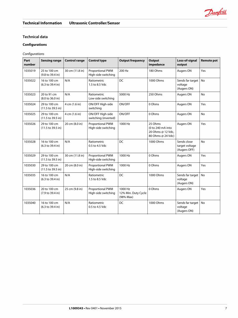
Configurations
Configurations
Partnumber
Sensing range Control range Control type Output frequency Outputimpedance
Loss-of-signaloutput
Remote pot
1035019 25 to 100 cm(9.8 to 39.4 in)
30 cm (11.8 in) Proportional PWMHigh-side switching
200 Hz 180 Ohms Augers ON Yes
1035022 16 to 100 cm(6.3 to 39.4 in)
N/A Ratiometric1.5 to 8.5 Vdc
DC 1000 Ohms Sends far targetvoltage(Augers ON)
No
1035023 20 to 91 cm(8.0 to 36.0 in)
N/A RatiometricLow-side switching
5000 Hz 250 Ohms Augers ON No
1035024 29 to 100 cm(11.5 to 39.5 in)
4 cm (1.6 in) ON/OFF High-sideswitching
ON/OFF 0 Ohms Augers ON Yes
1035025 29 to 100 cm(11.5 to 39.5 in)
4 cm (1.6 in) ON/OFF High-sideswitching (inverted)
ON/OFF 0 Ohms Augers ON No
1035026 29 to 100 cm(11.5 to 39.5 in)
20 cm (8.0 in) Proportional PWMHigh-side switching
1000 Hz 25 Ohms(0 to 240 mA into20 Ohms @ 12 Vdc,80 Ohms @ 24 Vdc)
Augers ON Yes
1035028 16 to 100 cm(6.3 to 39.4 in)
N/A Ratiometric0.5 to 4.5 Vdc
DC 1000 Ohms Sends closetarget voltage(Augers OFF)
No
1035029 29 to 100 cm(11.5 to 39.5 in)
30 cm (11.8 in) Proportional PWMHigh-side switching
1000 Hz 0 Ohms Augers ON Yes
1035030 29 to 100 cm(11.5 to 39.5 in)
20 cm (8.0 in) Proportional PWMHigh-side switching
1000 Hz 0 Ohms Augers ON Yes
1035035 16 to 100 cm(6.3 to 39.4 in)
N/A Ratiometric1.5 to 8.5 Vdc
DC 1000 Ohms Sends far targetvoltage(Augers ON)
No
1035036 20 to 100 cm(7.9 to 39.4 in)
25 cm (9.8 in) Proportional PWMHigh-side switching
1000 Hz12% Min. Duty Cycle(98% Max)
0 Ohms Augers ON Yes
1035040 16 to 100 cm(6.3 to 39.4 in)
N/A Ratiometric0.5 to 4.5 Vdc
DC 1000 Ohms Sends far targetvoltage(Augers ON)
No
Technical Information Ultrasonic Controller/Sensor
Technical data
L1009343 • Rev 0401 • November 2015 7

Dimensions
mm [inches]
P200 056
77.22 [3.04]
102.62 [4.04]
144.32 [5.68]
96.52 [3.80]
107.75 [4.24]
84.90 [3.34]
44.45 [1.75]
Technical Information Ultrasonic Controller/Sensor
Technical data
8 L1009343 • Rev 0401 • November 2015
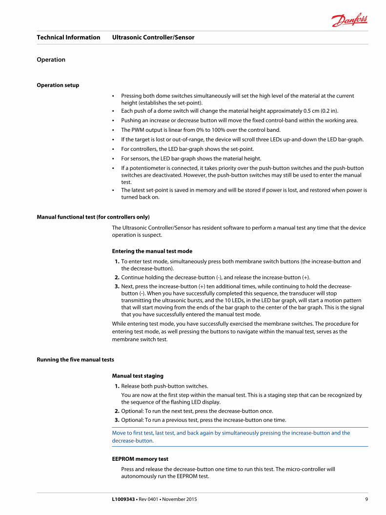
Operation setup
• Pressing both dome switches simultaneously will set the high level of the material at the currentheight (establishes the set-point).
• Each push of a dome switch will change the material height approximately 0.5 cm (0.2 in).
• Pushing an increase or decrease button will move the fixed control-band within the working area.
• The PWM output is linear from 0% to 100% over the control band.
• If the target is lost or out-of-range, the device will scroll three LEDs up-and-down the LED bar-graph.
• For controllers, the LED bar-graph shows the set-point.
• For sensors, the LED bar-graph shows the material height.
• If a potentiometer is connected, it takes priority over the push-button switches and the push-buttonswitches are deactivated. However, the push-button switches may still be used to enter the manualtest.
• The latest set-point is saved in memory and will be stored if power is lost, and restored when power isturned back on.
Manual functional test (for controllers only)
The Ultrasonic Controller/Sensor has resident software to perform a manual test any time that the deviceoperation is suspect.
Entering the manual test mode
1. To enter test mode, simultaneously press both membrane switch buttons (the increase-button andthe decrease-button).
2. Continue holding the decrease-button (-), and release the increase-button (+).
3. Next, press the increase-button (+) ten additional times, while continuing to hold the decrease-button (-). When you have successfully completed this sequence, the transducer will stoptransmitting the ultrasonic bursts, and the 10 LEDs, in the LED bar graph, will start a motion patternthat will start moving from the ends of the bar graph to the center of the bar graph. This is the signalthat you have successfully entered the manual test mode.
While entering test mode, you have successfully exercised the membrane switches. The procedure forentering test mode, as well pressing the buttons to navigate within the manual test, serves as themembrane switch test.
Running the five manual tests
Manual test staging
1. Release both push-button switches.
You are now at the first step within the manual test. This is a staging step that can be recognized bythe sequence of the flashing LED display.
2. Optional: To run the next test, press the decrease-button once.
3. Optional: To run a previous test, press the increase-button one time.
Move to first test, last test, and back again by simultaneously pressing the increase-button and thedecrease-button.
EEPROM memory test
Press and release the decrease-button one time to run this test. The micro-controller willautonomously run the EEPROM test.
Technical Information Ultrasonic Controller/Sensor
Operation
L1009343 • Rev 0401 • November 2015 9

A successful completion of the test will result in all LEDs being on. If this test fails, then all LEDs will flash.If the LEDs flash, then one or more EEPROM locations are not capable of being reprogrammed.
LED Test will re-run by pressing and releasing increase-button.
LED test
1. Press and release the decrease-button one time to begin this next test.
Upon entry into this test, each LED will turn on, and then off again, in sequence.
2. The operator must verify that each individual LED in the bar-graph is functional. At no time shouldtwo LEDs be on simultaneously.
EEPROM memory test will re-run by pressing and releasing increase-button.
Potentiometer/LED test
Press and release the decrease-button one time to begin this test.
If the device is capable of being equipped with a potentiometer, then turning the pot will change thelights on the display. Depending on how the pot is connected, turning it fully one direction will result inall LEDs on. Turning it all the way in the other direction will result in all LEDs off, except for LED 0 (theleast significant LED in the LED bar graph). LED 0 will always be on during this test.
As the LED bar-graph increases in length, the output from the PWM connection will increase, as well.
If no potentiometer is connected, then some arbitrary output will result along with some arbitrary LEDdisplay.
C Caution
If the paver’s augers are set in an automatic mode, then running this test will turn the augers.
Potentiometer/LED test will rerun by pressing and releasing the increase-button.
Ultrasonic transceiver/LED/output driver test
Press and release the decrease-button one time to enter this test.The ultrasonic transducer will now activate and start transmitting signals and receiving the echoes.The transducer must be pointed toward a suitable target to complete this test. Also, there must be anappropriate method of measuring the PWM output from the valve driver.
As the device is moved toward the target, the PWM output will either go to its minimum duty cycle or itsmaximum duty cycle, depending on the device configuration.
As the device is moved away from the target, the PWM output will go to its maximum duty cycle or itsminimum duty cycle, depending on the device configuration. As the device moves away from the target,the LED display will go from all LEDs on to all LEDs off, except for the least significant LED in the array.LED 0 is always on during this test.
C Caution
If the paver’s augers are set in an automatic mode, then running this test will turn the augers.
Ultrasonic transceiver/LED/output driver test will re-run by pressing and releasing increase-button.
Exiting manual test mode
Pressing and releasing the decrease-button one time will allow the Ultrasonic Controller/Sensor toenter this test.
You will be able to recognize this test by observing the transducer and the LED bar graph. Thetransducer will stop transmitting and the 10 LEDs, in the LED bar graph, will start a motion patternthat will start moving from the ends of the bar graph to the center of the bar graph.
Technical Information Ultrasonic Controller/Sensor
Operation
10 L1009343 • Rev 0401 • November 2015

Exiting manual test mode will re-run by pressing and releasing increase-button.
Manual test mode is exited and normal operation resumes by simultaneously pressing the increase-button and the decrease-button.
Technical Information Ultrasonic Controller/Sensor
Operation
L1009343 • Rev 0401 • November 2015 11

1035019, 1035026, 1035029, 1035030, 1035036
Ultrasonic
Target Surface
Auger
Electrical DisplacementControl
Hydrostatic Transmission
Material Flow
Coil CordMachine Wiring
OptionalRemote Adjust Pot
Machine Bulkhead
P200 058
1035024, 1035025
Ultrasonic Controller
Target Surface
Auger
Material Flow
Coil CordMachine Wiring
OptionalRemote Adjust Pot
Machine Bulkhead
P200 059
MFSNP2
Gear Pump
3-way Valve
Technical Information Ultrasonic Controller/Sensor
System diagram
12 L1009343 • Rev 0401 • November 2015

1035022 open circuit, 1035028 closed circuit, 1035035, 1035040
Ultrasonic Sensor
Target Surface
Auger
Electrical DisplacementControl
Hydrostatic Transmission
Material Flow
Coil CordMachine Wiring
Panel or Controller
Optional Wand Sensor
P200 060
Technical Information Ultrasonic Controller/Sensor
System diagram
L1009343 • Rev 0401 • November 2015 13

1035019, 1035026
Control range of the pulse-width modulated output (pin D)
P200 061
Out
put C
urre
nt (m
A)
Distance from Target (cm)
Dis
tanc
e Ad
just
Kno
bFu
ll Cl
ock
Dis
tanc
e Ad
just
Kno
bFu
ll Co
unte
r-Cl
ock
Height adjust
240
200
160
120
80
40
0
0 20 40 60 80 100
12 Vdc Supply
1035024, 1035025
Control range of the ON/OFF output (pin D)
P200 062
Out
put d
rive
Distance from target (cm)
12 VdcSupply
Height Adjust
Power
Open
Full ClockwiseDistance Adjust Knob
0 26 30 76 80
Full Counter-Clockwise
Technical Information Ultrasonic Controller/Sensor
Control diagram
14 L1009343 • Rev 0401 • November 2015

1035022, 1035028, 1035035, 1035040
Control range of the analog output (pin B) for the 103522, 1035028 Ultrasonic Control/Sensor. Supply voltageis 12 or 24 Vdc and output impedances 1 k ohm.
P200 063
0
0 20 40 60 80 100
Out
put v
olta
ge (V
dc)
Distance from target (cm)
2.0
4.0
6.0
8.0
1035028, 1035040
1035022, 1035035
Technical Information Ultrasonic Controller/Sensor
Control diagram
L1009343 • Rev 0401 • November 2015 15

Danfoss Power Solutions is a global manufacturer and supplier of high-quality hydraulic andelectronic components. We specialize in providing state-of-the-art technology and solutionsthat excel in the harsh operating conditions of the mobile off-highway market. Building onour extensive applications expertise, we work closely with our customers to ensureexceptional performance for a broad range of off-highway vehicles.
We help OEMs around the world speed up system development, reduce costs and bringvehicles to market faster.
Danfoss – Your Strongest Partner in Mobile Hydraulics.
Go to www.powersolutions.danfoss.com for further product information.
Wherever off-highway vehicles are at work, so is Danfoss. We offer expert worldwide supportfor our customers, ensuring the best possible solutions for outstanding performance. Andwith an extensive network of Global Service Partners, we also provide comprehensive globalservice for all of our components.
Please contact the Danfoss Power Solution representative nearest you.
Local address:
Danfoss Power Solutions GmbH & Co. OHGKrokamp 35D-24539 Neumünster, GermanyPhone: +49 4321 871 0
Danfoss Power Solutions ApSNordborgvej 81DK-6430 Nordborg, DenmarkPhone: +45 7488 2222
Danfoss Power Solutions (US) Company2800 East 13th StreetAmes, IA 50010, USAPhone: +1 515 239 6000
Danfoss Power Solutions Trading(Shanghai) Co., Ltd.Building #22, No. 1000 Jin Hai RdJin Qiao, Pudong New DistrictShanghai, China 201206Phone: +86 21 3418 5200
Danfoss can accept no responsibility for possible errors in catalogues, brochures and other printed material. Danfoss reserves the right to alter its products without notice. This also applies toproducts already on order provided that such alterations can be made without changes being necessary in specifications already agreed.All trademarks in this material are property of the respective companies. Danfoss and the Danfoss logotype are trademarks of Danfoss A/S. All rights reserved.
L1009343 • Rev 0401 • November 2015 www.danfoss.com © Danfoss A/S, 2015
Products we offer:
• Bent Axis Motors
• Closed Circuit Axial PistonPumps and Motors
• Displays
• Electrohydraulic PowerSteering
• Electrohydraulics
• Hydraulic Power Steering
• Integrated Systems
• Joysticks and ControlHandles
• Microcontrollers andSoftware
• Open Circuit Axial PistonPumps
• Orbital Motors
• PLUS+1® GUIDE
• Proportional Valves
• Sensors
• Steering
• Transit Mixer Drives
Comatrolwww.comatrol.com
Schwarzmüller-Inverterwww.schwarzmueller-inverter.com
Turolla www.turollaocg.com
Hydro-Gearwww.hydro-gear.com
Daikin-Sauer-Danfosswww.daikin-sauer-danfoss.com