UltraFlex Mini PC V2 · 2018-06-19 · This manual provides a comprehensive guide to the UltraFlex...
24
WEY Technology AG · MAN22771_E06.docx · 18.04.2018 Dorfstrasse 57 · 8103 Unterengstringen · Schweiz · T +41 44 751 89 89 · [email protected] · www.weytec.com 1 MANUAL FOR ULTRAFLEX MINI PC V2 Part No. 22771
Transcript of UltraFlex Mini PC V2 · 2018-06-19 · This manual provides a comprehensive guide to the UltraFlex...

WEY Technology AG · MAN22771_E06.docx · 18.04.2018 Dorfstrasse 57 · 8103 Unterengstringen · Schweiz · T +41 44 751 89 89 · [email protected] · www.weytec.com
1
MANUAL FOR ULTRAFLEX MINI PC V2 Part No. 22771

WEY Technology AG · MAN22771_E06.docx · 18.04.2018 Dorfstrasse 57 · 8103 Unterengstringen · Schweiz · T +41 44 751 89 89 · [email protected] · www.weytec.com
2
Manual Revision History
Copyright
WEY Technology AG is the exclusive owner of the copyrights for the delivered programs, the documentation and manuals and the operating instructions, including the charts and layouts contained therein. They may not be duplicated, saved, transferred, disseminated or made available to third parties, neither in whole nor in part, without the prior written consent of WEY Technology AG. They may only be used for the intended operation of a legally acquired product or program within the business of the purchaser.
© WEY Technology AG
Version Date Remarks Initials E01 11.07.2016 Draft JRU/DAI E02 31.10.2016 Edit Contacts JRU E03 25.11.2016 Edit Specification JRU E04 23.01.2016 Edit Specification JRU E05 03.04.2018 New Design JRU

WEY Technology AG · MAN22771_E06.docx · 18.04.2018 Dorfstrasse 57 · 8103 Unterengstringen · Schweiz · T +41 44 751 89 89 · [email protected] · www.weytec.com
3
Table of Contents
1 Read this first ............................................................................................................................................................................. 5
1.1 Safety Instructions .................................................................................................................................................................... 5
1.1.1 Power supply, Ports and Cables ..................................................................................................................................................................................................................................................... 5
1.1.2 Housing and opening the housing .............................................................................................................................................................................................................................................. 5
1.1.3 Parts and Service ........................................................................................................................................................................................................................................................................................... 6
1.1.4 Environmental conditions and protection against electric shock ................................................................................................................................................................ 6
1.1.5 Disposal of Old Electrical and Electronic Equipment ............................................................................................................................................................................................... 6
1.2 Symbols / Notes ........................................................................................................................................................................ 7
1.3 Warranty Limitations ............................................................................................................................................................... 7
2 General Description .................................................................................................................................................................. 8
2.1 Introduction ............................................................................................................................................................................... 8
2.2 Benefits ...................................................................................................................................................................................... 8
2.3 Application Example 1 .............................................................................................................................................................. 9
2.4 Application Example 2 ............................................................................................................................................................. 9
2.5 Application Example 3 ............................................................................................................................................................ 10
3 Product Overview .................................................................................................................................................................... 11
3.1 Technical Specifications .......................................................................................................................................................... 11
3.2 Operating Conditions .............................................................................................................................................................. 12
3.3 Approval ................................................................................................................................................................................... 12
3.4 Available models ...................................................................................................................................................................... 13
3.5 Components .............................................................................................................................................................................. 14
3.5.1 Front View .......................................................................................................................................................................................................................................................................................................... 14
3.6 Indicator LEDs .......................................................................................................................................................................... 15
3.6.1 Front view ............................................................................................................................................................................................................................................................................................................15
3.6.2 Chassis ................................................................................................................................................................................................................................................................................................................... 16
3.6.3 Front View 6 slot Standalone/Rear View chassis (Power Supply) ........................................................................................................................................................... 16
3.7 Connectors and Indicators ...................................................................................................................................................... 17
3.7.1 Power Switch ....................................................................................................................................................................................................................................................................................................17
3.7.2 HDD activity LED ........................................................................................................................................................................................................................................................................................17
3.7.3 2-3 x Mini DP ....................................................................................................................................................................................................................................................................................................17
3.7.4 3-4 x Mini DP ...................................................................................................................................................................................................................................................................................................17
3.7.5 2 x USB 3.0 SuperSpeed .......................................................................................................................................................................................................................................................................17
3.7.6 2 x USB 2.0 HighSpeed .........................................................................................................................................................................................................................................................................17
3.7.7 Audio in and Audio out .........................................................................................................................................................................................................................................................................17
3.7.8 2 x Gigabit Ethernet connecters with Link and Activity LEDs ......................................................................................................................................................................17
3.8 On board Connectors and Jumpers ....................................................................................................................................... 18
WEY Technology AG · MAN22771_E06.docx · 18.04.2018 Dorfstrasse 57 · 8103 Unterengstringen · Schweiz · T +41 44 751 89 89 · [email protected] · www.weytec.com
4
3.8.1 SATA Data connectors ......................................................................................................................................................................................................................................................................... 18
3.8.2 Audio in selection ....................................................................................................................................................................................................................................................................................... 18
3.8.3 SATA power ..................................................................................................................................................................................................................................................................................................... 18
3.9 Hardware Accessories ............................................................................................................................................................. 19
4 Determining the Configuration ............................................................................................................................................. 20
4.1 Collecting information ........................................................................................................................................................... 20
4.1.1 Desk ......................................................................................................................................................................................................................................................................................................................... 20
4.1.2 User .......................................................................................................................................................................................................................................................................................................................... 20
4.1.3 IT Policy ............................................................................................................................................................................................................................................................................................................... 20
5 Operational Guide .................................................................................................................................................................... 21
5.1 Assembly ................................................................................................................................................................................... 21
5.2 Installation ................................................................................................................................................................................ 21
5.3 Custom UltraFlex image ......................................................................................................................................................... 21
6 Supported Video Resolutions ............................................................................................................................................... 22
6.1 Onboard Outputs DP1 – DP3 ................................................................................................................................................. 22
6.2 Triple External Outputs DP4 – DP6 ..................................................................................................................................... 22
6.3 Quad External Outputs DP4 – DP7 ....................................................................................................................................... 22
7 Troubleshooting ...................................................................................................................................................................... 23
8 Contacts ................................................................................................................................................................................... 24

WEY Technology AG · MAN22771_E06.docx · 18.04.2018 Dorfstrasse 57 · 8103 Unterengstringen · Schweiz · T +41 44 751 89 89 · [email protected] · www.weytec.com
5
1 Read this first
This manual provides a comprehensive guide to the UltraFlex Mini PC V2.
1.1 Safety Instructions
NOTICE
Risk of property damage
Carefully read this reference manual.
Only original parts and accessories recommended by WEY Technology AG and peripheral devices in accordance with the DIN EN 60950 regulations may be used.
Place the equipment on a stable surface or install it in appropriate racks and provide good ventilation!
Use the equipment exclusively for its hereby specified purposes and keep it unplugged during installation and handling!
1.1.1 Power supply, Ports and Cables
WARNING
Risk of fire or electric shock
Ensure correct voltage. (110/230V)
Use only affiliated AC power adapter.
Connect equipment to easily accessible, grounded main power outlet.
Replace worn-out or damaged cables / AC power adapters immediately.
Do not overload power circuits.
Disconnect adapter from mains if equipment remains unused for a longer period of time.
1.1.2 Housing and opening the housing
WARNING
Risk of electric shock
Do not touch any electrical contacts or devices.
Do not insert any objects into the openings of the housing.
Do not open the housing or remove the cover plate.
WEY Technology AG · MAN22771_E06.docx · 18.04.2018 Dorfstrasse 57 · 8103 Unterengstringen · Schweiz · T +41 44 751 89 89 · [email protected] · www.weytec.com
6
1.1.3 Parts and Service
NOTICE
Risk of property damage
All WEY products and their attached units may only be opened and repaired by qualified and authorized service personnel.
For fiber optic equipment only personnel familiar with the handling and general safety guidelines for optical equipment are entitled to repair such devices.
1.1.4 Environmental conditions and protection against electric shock
WARNING
Risk of electric shock or explosion
Do not place WEY Products and their peripheral equipment near heat generating devices or humidifiers.
Do not expose WEY Products to constant sunlight or wetness.
Do not use Wey Products in rooms containing easily inflammable, ethereal or volatile gas.
Avoid environmental hazards such as dust, dirt, food, liquids, chemicals, temperature extremes, vibrations and abrupt changes in humidity or temperature.
In case of condensation on or within the units, allow sufficient time for the moisture to evaporate.
Do not use artificial means to speed up the drying process.
Before using the equipment again, verify that all connected units are thoroughly dry.
1.1.5 Disposal of Old Electrical and Electronic Equipment
NOTICE
Risk of negative consequences for the environment
The recycling of materials helps to conserve natural resources.
This symbol on WEY products indicates that this product shall not be treated as household waste. Instead it should be handed over to the applicable collection point for the recycling of electrical and electronic equipment.
By ensuring this product is disposed of correctly, you help prevent potential negative consequences for the environment and human health, which could otherwise be caused by inappropriate waste handling.

WEY Technology AG · MAN22771_E06.docx · 18.04.2018 Dorfstrasse 57 · 8103 Unterengstringen · Schweiz · T +41 44 751 89 89 · [email protected] · www.weytec.com
7
1.2 Symbols / Notes
WARNING
Indicates a hazardous situation that, if not avoided, could result in death or serious injury.
NOTICE
Indicates information considered important, but not hazard-related (e.g. messages relating to property damage).
The following tips and hints should be followed to enhance the usability of the product.
Arrow This arrow points to an action or a sequence of actions to be taken.
1.3 Warranty Limitations The warranty term for the WEY Products is 12 months as per delivery date. The manufacturer does not assume any general liability or liability to pay any compensation or damages if any part of the manufacturer’s instructions are violated. Warranty and liability shall not exceed the minimal extent as defined by applicable law and Wey Technology’s General Sales Terms and Delivery Conditions. All other warranty regulations require the written consent of Wey Technology AG. Excluded from warranty are:
• Physical damage due to transport or mishandling • Chemical damage due to mishandling • Electrical damage not due to failure of components

WEY Technology AG · MAN22771_E06.docx · 18.04.2018 Dorfstrasse 57 · 8103 Unterengstringen · Schweiz · T +41 44 751 89 89 · [email protected] · www.weytec.com
8
2 General Description
2.1 Introduction
The UltraFlex Mini PC V2 is a full function PC optimized for size and power consumption. The UltraFlex Mini PC V2 is mounted in a standalone with one or two 12V power supplies or 19” chassis with single or dual PSUs.
UltraFlex Mini PC V2 is configured to run Windows 7 Pro, Windows 8.1 Pro and Windows 10 Pro.
2.2 Benefits
• UltraFlex Mini PC V2 can support up to seven screens • Extremely compact design with redundant power supply option • Fast boot and performance using SSD • Dual Gigabit Ethernet • Dual Hispeed USB2.0 • Dual SuperSpeed USB3.0 • RAID option • Quad Core processors

WEY Technology AG · MAN22771_E06.docx · 18.04.2018 Dorfstrasse 57 · 8103 Unterengstringen · Schweiz · T +41 44 751 89 89 · [email protected] · www.weytec.com
9
2.3 Application Example 1
The following diagram shows a standalone UltraFlex Mini PC V2 driving 7 screens:
2.4 Application Example 2
The following diagram shows chassis mounted UltraFlex Mini PC V2s each driving 3 screens:
Figure 1 - Example 1
Figure 2 - Example 2

WEY Technology AG · MAN22771_E06.docx · 18.04.2018 Dorfstrasse 57 · 8103 Unterengstringen · Schweiz · T +41 44 751 89 89 · [email protected] · www.weytec.com
10
2.5 Application Example 3
The following diagram shows chassis mounted UltraFlex Mini PC V2s driving a combination of screens:
Figure 3 - Example 3

WEY Technology AG · MAN22771_E06.docx · 18.04.2018 Dorfstrasse 57 · 8103 Unterengstringen · Schweiz · T +41 44 751 89 89 · [email protected] · www.weytec.com
11
3 Product Overview
3.1 Technical Specifications
UltraFlex Mini PC V2 Part No. 2277xx Picture
Dimensions – excluding housing Size W/D/H (mm) 2 Slot 180 x 128 x 40 / 3 Slot 180 x 128 x 60 / 4 Slot 180 x 128 x 80 Weight (g) 460 - 684 Electrical Characteristics Power Supply 2 x 100-240V AC (2x Switched Power Supplies for redundancy /12V 14.1A P/N
23537_180W) Power Consumption 16W - max 75W (power consumption depends on the used CPU and optional PCI-E card) Video Resolution
Intel® Celeron® N3160 HD Graphics 400 2x 2560x1600@60Hz Intel® Core™ i5 - 6442EQ HD Graphics 530 3x 4096x2304@60Hz Intel® Core™ i7 - 6822EQ HD Graphics 530 3x 4096x2304@60Hz
Audio Stereo 48KHz 16/Bit (1Vrms 20Hz – 20KHz) Data 2x USB 2.0 HighSpeed 2x USB 3.0 SuperSpeed and 2x Gigabit Ethernet MTBF 80KHrs Interfaces / Connectors USB 2 x USB 3.0 Type A SuperSpeed 2 x USB 2.0 Type A HighSpeed SATA 2 x SATA 6Gb/s (SATA-III) max. 5Watt per port mSATA 1 x mSATA 6Gb/s Ethernet 2 x Gigabit RJ45
Video 3 x mini DP* outputs expandable up to 7 mini DP outputs with additional PCI-E graphics card
Audio
3mm jack socket for stereo line out 3mm jack socket for stereo line in or mic selectable via on board jumpers
Configuration / Diagnostics GUI Yes SNMP Management Yes Indicator LEDs Ethernet link and activity on each RJ45 connector Power switch Switch inclusive HDD/SSD activity LED to shutdown/power up module
*Only two DisplayPort outputs are supports on Celeron processor.

WEY Technology AG · MAN22771_E06.docx · 18.04.2018 Dorfstrasse 57 · 8103 Unterengstringen · Schweiz · T +41 44 751 89 89 · [email protected] · www.weytec.com
12
3.2 Operating Conditions
Operating temperature: 8 – 40 °C Storage temperature: 0 – 60 °C Operating location: Indoor use Relative humidity: 45 – 85 % non-condensing Operating altitude: Max. 2000 m
3.3 Approval The UltraFlex Mini PC V2 is Class B FCC and CE conform and approved.

WEY Technology AG · MAN22771_E06.docx · 18.04.2018 Dorfstrasse 57 · 8103 Unterengstringen · Schweiz · T +41 44 751 89 89 · [email protected] · www.weytec.com
13
3.4 Available models
Customised configurations available on request
Intel® Celeron® N3160
4 Core, 1.6/2.24 GHz
2MB cache
Intel® Core ™ i5 – 6442EQ 4 Core, 1.9/2.7 GHz, 6 MB cache
Intel® Core ™ i7 – 6822EQ 4 Core, 2.0/2.8 GHz, 8 MB cache
2 Video Out 3 Video Out 6 Video Out 7 Video Out 3 Video Out 2 Slot Version 2 Slot Version 3 Slot Version 3 Slot Version 4 Slot Version
Intel HD Graphics 400
2x 2560x1600@60Hz
Intel HD Graphics 530 3x 4096x2304@60Hz
Intel HD Graphics 530 3x 4096x2304@60Hz
& NV Quadro P400
3x 4096x2160@60Hz /
1x 5120x2880@60Hz
Intel HD Graphics 530 3x 4096x2304@60Hz
& NV Quadro P600
4x 4096x2160@60Hz /
4x 5120x2880@60Hz
Intel HD Graphics 530 3x 4096x2304@60Hz
& RAID Slot Enclosure
Power consumption 16 W max.
Power consumption 35 W max.
Power consumption 60 W max.
Power consumption 75 W max.
Power consumption 45 W max.
2x Gigabit Ethernet 2x USB 3.0, 2x USB 2.0 Audio line out stereo, line in/mic in (3.5 mm jack) 30 – 980 GB Internal mSATA SSD (Solid State Drive)
4 – 8 GB DDR3L SD-RAM
4 – 32 GB DDR4 SD-RAM
Optional - 120 – 980 GB External 2.5" SATA (SSD RAID) - PCI Express x16 Windows License

WEY Technology AG · MAN22771_E06.docx · 18.04.2018 Dorfstrasse 57 · 8103 Unterengstringen · Schweiz · T +41 44 751 89 89 · [email protected] · www.weytec.com
14
3.5 Components
The following images show the UltraFlex Mini PC V2 including connectors and LEDs.
3.5.1 Front View
1. Power switch and HDD/SSD activity LED
2. 3 x Mini DP
3. 4 x Mini DP – optional alternatives are none or 2 x DP
4. 2 x USB 3.0 SuperSpeed (blue) 2x USB 2.0 HighSpeed (black)
5. Audio in (blue) / Microphone in (pink) and Audio out (green)
6. 2 x Gigabit Ethernet connecters with Link and Activity LEDs
Figure 4 - Components

WEY Technology AG · MAN22771_E06.docx · 18.04.2018 Dorfstrasse 57 · 8103 Unterengstringen · Schweiz · T +41 44 751 89 89 · [email protected] · www.weytec.com
15
3.6 Indicator LEDs
When lit up and/or blinking, the LED colors indicate the following states:
3.6.1 Front view
HDD = HDD/SSD activity (Blinking)
Ethernet Left = Gigabit Ethernet link established
Ethernet Right = Link/Activity Data send/receive
On when link established and (Steady)
Blinking when data sent/received (Blinking)
Gigabit connection - steady yellow LED and steady or blinking green LED
10/100M connection - steady or blinking green LED only
Figure 5 - UltraFlex V2 front indicators

WEY Technology AG · MAN22771_E06.docx · 18.04.2018 Dorfstrasse 57 · 8103 Unterengstringen · Schweiz · T +41 44 751 89 89 · [email protected] · www.weytec.com
16
3.6.2 Chassis
1. Power Supply 1 2. Power Supply 2
Power Supply = Power Supply OK
= Power Supply Error (Blinking)
3.6.3 Front View 6 slot Standalone/Rear View chassis (Power Supply)
Power Supply = Power Supply OK
= Power Supply Error (Blinking)
Figure 6 - Chassis front
Figure 7 - PSU Indicator LEDs
2 1
WEY Technology AG · MAN22771_E06.docx · 18.04.2018 Dorfstrasse 57 · 8103 Unterengstringen · Schweiz · T +41 44 751 89 89 · [email protected] · www.weytec.com
17
3.7 Connectors and Indicators
3.7.1 Power Switch
The Power switch can be used to instigate a power down or power up of the module. Note that this does not shut down or start up the power to the UltraFlex.
3.7.2 HDD activity LED
The LED on the power switch is illuminated when the HDD/SSD is accessed and gives an indication of activity.
3.7.3 2-3 x Mini DP
The UltraFlex is capable of directly driving two - three screens via the Mini DP connectors.
3.7.4 3-4 x Mini DP
If the UltraFlex is configured with an optional graphics card either 3 x Mini DP or 4 x Mini DP connectors are available to connect additional screens. These connectors can use active or passive adaptors for DVI/HDMI screens.
3.7.5 2 x USB 3.0 SuperSpeed
Each USB 3.0 SuperSpeed connector supports USB 3.0 Superspeed and is backward compatible with USB 2 and USB 1 devices.
3.7.6 2 x USB 2.0 HighSpeed
Each USB 2.0 HighSpeed connector supports USB 2.0 HighSpeed and is backward compatible with USB 1 devices.
3.7.7 Audio in and Audio out
Audio in is jumper selectable to be a mic or line level stereo input via a standard 3mm socket. Audio out is a line level stereo output via a standard 3mm socket.
3.7.8 2 x Gigabit Ethernet connecters with Link and Activity LEDs
Each RJ45 connector provides Gigabit Ethernet connectivity.
WEY Technology AG · MAN22771_E06.docx · 18.04.2018 Dorfstrasse 57 · 8103 Unterengstringen · Schweiz · T +41 44 751 89 89 · [email protected] · www.weytec.com
18
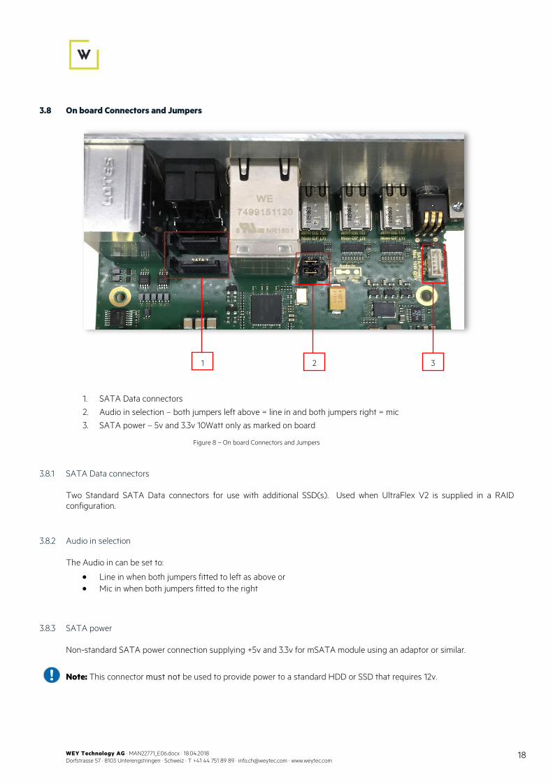
3.8 On board Connectors and Jumpers
1. SATA Data connectors
2. Audio in selection – both jumpers left above = line in and both jumpers right = mic
3. SATA power – 5v and 3.3v 10Watt only as marked on board
3.8.1 SATA Data connectors
Two Standard SATA Data connectors for use with additional SSD(s). Used when UltraFlex V2 is supplied in a RAID configuration.
3.8.2 Audio in selection
The Audio in can be set to:
• Line in when both jumpers fitted to left as above or • Mic in when both jumpers fitted to the right
3.8.3 SATA power
Non-standard SATA power connection supplying +5v and 3.3v for mSATA module using an adaptor or similar.
Note: This connector must not be used to provide power to a standard HDD or SSD that requires 12v.
Figure 8 – On board Connectors and Jumpers
1 2 3

WEY Technology AG · MAN22771_E06.docx · 18.04.2018 Dorfstrasse 57 · 8103 Unterengstringen · Schweiz · T +41 44 751 89 89 · [email protected] · www.weytec.com
19
3.9 Hardware Accessories
The following accessories (depending on option) are required to ensure correct and safe operation of the UltraFlex Mini PC V2.
Part Nr. Product Name Picture
23563V12GT5 PSU GlobTek 12VDC/5A 60W with LED
23646_4 WEY Box 4 slot 3U including Fan and 2 power sockets (external 12V PSU required)
23641_4 WEY Box 4 slot 3U including fan, 12V PSU and 2 external 12V power socket
23641_6 WEY Box 6 slot 3U including fan, 12V PSU and 2 external 12V power socket
23129DP180W Chassis 19" 3U DVI / VSS2 Desk Rack 16 Slots Address-Bus incl. 2xPSU +12V (23537_180W) Jumpers out (4xMiniDin 3pin Power)
20259S Mini DisplayPort to DVI Single-Link Active Converter
20843L1 Cable Mini DisplayPort to DVI Active Adapter Converter Cable – mDP to DVI 2560x1600 0.9m
20843L2 Cable Mini DisplayPort to DVI Active Adapter Converter Cable – mDP to DVI 2560x1600 1.8m
20844L2 Cable Mini DisplayPort to DisplayPort M/M 1.8m
20844L3 Cable Mini DisplayPort to DisplayPort M/M 3m
20844L4 Cable Mini DisplayPort to DisplayPort M/M 4m
Figure 9 – Accessories

WEY Technology AG · MAN22771_E06.docx · 18.04.2018 Dorfstrasse 57 · 8103 Unterengstringen · Schweiz · T +41 44 751 89 89 · [email protected] · www.weytec.com
20
4 Determining the Configuration
The UltraFlex Mini PC V2 has the following options:
• Standalone or chassis • Celeron, i5 or i7 processor • 4, 8, 16,or 32GB RAM • 2 Screens (2x MiniDP), 3 Screen (3x MiniDP), 6 screens (6x MiniDP) or 7 Screen (7x MiniDP) • 0 - 980GB mSATA SSD OR 120GB - 1TB SSD RAID 1 configuration • Windows 7 Pro x64, Windows 8.1 Pro x64, Windows 10 Pro x64 or no OS
Deployment position, workload, screens/position, local resilience requirement and company IT policy will determine the required options.
4.1 Collecting information
To determine the required UltraFlex options there are three key areas that need to be investigated: Desk; User and IT Policy.
4.1.1 Desk
The following will help determine Ultraflex options:
• Space in desk for Ultraflex • Number of screens to be connected to UltraFlex
4.1.2 User
The user work profile will help:
• Determine the local storage requirements • CPU power requirements
4.1.3 IT Policy
IT Policy/strategy will determine:
• RAID requirements • Local storage size • Local/virtualized ratio • OS image – internal or external

WEY Technology AG · MAN22771_E06.docx · 18.04.2018 Dorfstrasse 57 · 8103 Unterengstringen · Schweiz · T +41 44 751 89 89 · [email protected] · www.weytec.com
21
5 Operational Guide
5.1 Assembly
• Unwrap the equipment in a clean and dry environment. • Compare contents with the package contents list. If any listed item is missing or damaged, please contact
immediately your local customer service for assistance. • Ensure that the input voltage of the delivered power supplies comply with the mains voltage in your country. • Place the units in their designated locations, on a stable supporting surface or in an appropriate rack according to
the Safety Instructions and Environmental Conditions described in Chapter 1. • Make sure you slide the print boards into the rack without touching soldering points or components. • Do not move the equipment once installed. Provide sufficient ventilation.
5.2 Installation
• Mount the UltraFlex Mini PC V2 into the appropriate standalone box or 19” chassis. • Connect keyboard and mouse. • Connect the screens using MiniDP to DP cables or via WEY approved adaptors. • Connect LAN(s). • Connect Audio if required. • Connect power or power and Power Supplies units as required. • HDD/SSD activity, Ethernet Link and Ethernet Activity LEDs should illuminate as appropriate and the
UltraFlex desktop should appear on the screens.
5.3 Custom UltraFlex image
WEY can provide a customized image to a customer’s specification or provide support to customers building their own image. Please contact WEY for further information.

WEY Technology AG · MAN22771_E06.docx · 18.04.2018 Dorfstrasse 57 · 8103 Unterengstringen · Schweiz · T +41 44 751 89 89 · [email protected] · www.weytec.com
22
6 Supported Video Resolutions
The UltraFlex has two to three onboard video outputs DP1 – DP3 and an optional additional three or four video outputs DP4 – DP6 or DP4 – DP7.
6.1 Onboard Outputs DP1 – DP3
The on board UltraFlex video outputs DP1-DP3 are presented as MiniDP and will support up to 3 screens.
Installed Intel® Celeron® N3160 CPU:
• Each of the two outputs can individually support resolutions from 800 x 600 @ 60 Hz to 2560 x 1600 @ 60Hz. o 2x 2560x1600@60Hz (DP)
Installed Intel® Core ™ i5 – 6442EQ / Intel® Core ™ i7 – 6822EQ CPU:
• Each of the three outputs can individually support resolutions from 800 x 600 @ 60 Hz to 4096 x 2304 @ 60Hz. o 3x 4096x2304@60Hz (DP)
Note: Specification of the video output are differ, if an older Intel® i7-3517UE CPU is installed in the UltraFlex Mini PC V2. The specification of the video output for this CPU’s are described in the manual “UltraFlex Mini PC” (Part No. 22751).
6.2 Triple External Outputs DP4 – DP6
The external board UltraFlex video outputs DP4-DP6 are presented as MiniDP and will support up to an additional 3 screens. The use of any convertors may reduce the resolution from the maximum stated below:
• Display Resolutions: 3x 4096 x 2160 @ 60Hz / 1x 5120 x 2880 @60Hz.
6.3 Quad External Outputs DP4 – DP7
The external board UltraFlex video outputs DP4-DP5 are presented as MiniDP and will support up to an additional 4 screens. The use of any convertors may reduce the resolution from the maximum stated below:
• Display Resolutions: 4x 4096 x 2160 @ 60Hz / 4x 5120 x2880 @60Hz.

WEY Technology AG · MAN22771_E06.docx · 18.04.2018 Dorfstrasse 57 · 8103 Unterengstringen · Schweiz · T +41 44 751 89 89 · [email protected] · www.weytec.com
23
7 Troubleshooting
WEY products are highly reliable and very robust. Nonetheless, occasional operational faults may occur within the course of normal use.
Below you will find a list of common problems and corrective actions. If you cannot identify the problem or the actions fail to resolve the problem, please contact your local WEY Customer Support.
Problem Action
No power Ensure that all power supply units are firmly plugged to the mains and check the voltage with a voltmeter.
No Video Verify that all video connection cables are intact and firmly connected.
No Ethernet Link/Activity
Ensure that the RJ45 connectors and cables are secure and not damaged. Incorrect handling of sockets, plugs and cables causes bad connections.
No keyboard / No audio / No mouse
Ensure that all cables are intact and firmly connected.
Other Contact your local WEY Customer Support.

WEY Technology AG · MAN22771_E06.docx · 18.04.2018 Dorfstrasse 57 · 8103 Unterengstringen · Schweiz · T +41 44 751 89 89 · [email protected] · www.weytec.com
24
8 Contacts
Thank you for your interest in WEY.
You can establish direct contact with the department of your choice in the appropriate country.
Switzerland (Headquarters)
WEY Technology AG
Dorfstrasse 57 / Postfach 132 CH-8103 Unterengstringen
Switzerland
Tel +41 44 751 89 89 E-Mail [email protected]
Germany WEY Technology GmbH www.weytec.com/adressen
USA WEY Technology Inc. www.weytec.com/addresses
United Kingdom WEY Technology Ltd www.weytec.com/adressen
Singapore WEY Technology Singapore Pte. Ltd. www.weytec.com/addresses
France WEY Technology Sarl www.weytec.com/adressen
Australia WEY Technology Asia Pacific Pty. Ltd. www.weytec.com/addresses
Italy WEY Technology S.r.l. www.weytec.com/adressen
Taiwan WEY Technology Singapore Pte. Ltd. Taiwan Branch www.weytec.com/addresses
Austria WEY Technology Austria www.weytec.com/adressen
Hong Kong WEY Technology Hong Kong Ltd. www.weytec.com/addresses
Russia WEY Technology OOO www.weytec.com/adressen
India WEY Technology India Pvt. Ltd. www.weytec.com/addresses
Full location addresses and contact details are available on our website:
www.weytec.com/addresses
www.weytec.com [email protected] Please visit our website for further information about our company and products.