
ULTRA-WET COMBUSTION FOR HIGH EFFICIENCY, LOW EMISSION GAS ...
12
The Future of Gas Turbine Technology 6 th International Conference 17-18 October 2012, Brussels, Belgium Paper ID Number: 17 ULTRA-WET COMBUSTION FOR HIGH EFFICIENCY, LOW EMISSION GAS TURBINES Sebastian Göke, Eric Albin, Katharina Göckeler, Oliver Krüger, Sebastian Schimek, Steffen Terhaar, Christian Oliver Paschereit Chair of Fluid Dynamics – Hermann-Föttinger-Institut – Technische Universität Berlin Müller-Breslau Str. 8 D-10623 Berlin, Germany [email protected] ABSTRACT The ultra-wet gas turbine cycle offers a significant increase in efficiency compared to the dry gas turbine cycle. The steam also effectively inhibits the formation of NO x emissions and allows for operating the gas turbine on hydrogen-rich fuels, and even pure hydrogen. The challenge in the implementation of this new gas turbine cycle is the combustor, which must provide a stable combustion process at the ultra-wet conditions. The Chair of Fluid Dynamics at the Technische Universität Berlin has been active in the research of several fields related to the ultra-wet combustion process. In the current publication, the results of these research activities are summarized. The fundamental combustion physics are investigated with measurements and simulations of laminar, premixed methane flames. Steam dilution is found to have a significant effect on the flame speed. The ultra-wet combustion process is further investigated for a swirl-stabilized, and for a Rich-Quench- Lean (RQL) combustor. Both designs are commonly used in gas turbines. In experiments, the influence of the steam on the combustor flow field, flame shape, emission formation, and thermoacoustic behavior is assessed for methane and hydrogen fuels. Numerical tools are developed to calculate the flow field and to predict the formation of NO x and CO emissions. Excellent agreement with experimental results is achieved. The steam significantly changes the combustion process. Depending on the degree of humidity, different flame shapes can occur in the combustor. By changing both the axial position and the distribution of the heat release, steam content and fuel composition strongly influence the appearance of thermoacoustic pressure pulsations. The steam effectively restrains NO x formation. With the premixed combustor as well as the Rich-Quench-Lean combustor, single-digit NO x emissions are achieved even at near-stoichiometric conditions and high flame temperatures for natural gas and pure hydrogen fuel. INTRODUCTION Humidified gas turbines operating at ultra-wet conditions offer a significant increase in efficiency compared to the dry gas turbine cycle. In single-cycle application, ultra-wet gas turbines reach efficiencies comparable to state of the art combined-cycle power plants with up to 55% - 60% (Jonsson and Yan 2005, Pratt & Whitney 2002), but with much lower installation costs and emission levels. In contrast to the complex combined-cycle plants, ultra-wet gas turbines have a substantially smaller footprint. Depending on the cycle configuration, short start-up times and excellent load control capabilities can be achieved. Furthermore, the high steam content allows for low-NO x , near-stoichiometric combustor operation and thus enables post-combustion CO 2 capture at low cost, since the concentration of CO 2 reaches the highest possible value for air breathing gas turbines after condensation of the steam. Moreover, the reactivity of hydrogen is significantly reduced by the steam injection, thereby enabling clean and efficient operation using hydrogen-rich fuels from biomass or coal gasification, and pure hydrogen. The core technology of the ultra-wet cycle is the gas turbine combustor, which must provide a stable flame at these extreme conditions. The feasibility of the combustion concept was first shown at the Chair of Fluid Dynamics at the Technische Universität Berlin, and this new technology is now being developed in several projects. In 2009, the research was awarded the prestigious “Advanced
Transcript of ULTRA-WET COMBUSTION FOR HIGH EFFICIENCY, LOW EMISSION GAS ...
The Future of Gas Turbine Technology
6th
International Conference
17-18 October 2012, Brussels, Belgium
Paper ID Number: 17
ULTRA-WET COMBUSTION FOR HIGH EFFICIENCY, LOW EMISSION GAS
TURBINES
Sebastian Göke, Eric Albin, Katharina Göckeler, Oliver Krüger, Sebastian Schimek, Steffen Terhaar, Christian Oliver
Paschereit
Chair of Fluid Dynamics – Hermann-Föttinger-Institut –
Technische Universität Berlin
Müller-Breslau Str. 8
D-10623 Berlin, Germany
ABSTRACT
The ultra-wet gas turbine cycle offers a significant
increase in efficiency compared to the dry gas turbine
cycle. The steam also effectively inhibits the formation of
NOx emissions and allows for operating the gas turbine on
hydrogen-rich fuels, and even pure hydrogen. The
challenge in the implementation of this new gas turbine
cycle is the combustor, which must provide a stable
combustion process at the ultra-wet conditions.
The Chair of Fluid Dynamics at the Technische
Universität Berlin has been active in the research of
several fields related to the ultra-wet combustion process.
In the current publication, the results of these research
activities are summarized.
The fundamental combustion physics are investigated
with measurements and simulations of laminar, premixed
methane flames. Steam dilution is found to have a
significant effect on the flame speed.
The ultra-wet combustion process is further
investigated for a swirl-stabilized, and for a Rich-Quench-
Lean (RQL) combustor. Both designs are commonly used
in gas turbines. In experiments, the influence of the steam
on the combustor flow field, flame shape, emission
formation, and thermoacoustic behavior is assessed for
methane and hydrogen fuels. Numerical tools are
developed to calculate the flow field and to predict the
formation of NOx and CO emissions. Excellent agreement
with experimental results is achieved.
The steam significantly changes the combustion
process. Depending on the degree of humidity, different
flame shapes can occur in the combustor. By changing
both the axial position and the distribution of the heat
release, steam content and fuel composition strongly
influence the appearance of thermoacoustic pressure
pulsations.
The steam effectively restrains NOx formation. With
the premixed combustor as well as the Rich-Quench-Lean
combustor, single-digit NOx emissions are achieved even
at near-stoichiometric conditions and high flame
temperatures for natural gas and pure hydrogen fuel.
INTRODUCTION
Humidified gas turbines operating at ultra-wet
conditions offer a significant increase in efficiency
compared to the dry gas turbine cycle. In single-cycle
application, ultra-wet gas turbines reach efficiencies
comparable to state of the art combined-cycle power plants
with up to 55% - 60% (Jonsson and Yan 2005, Pratt &
Whitney 2002), but with much lower installation costs and
emission levels. In contrast to the complex combined-cycle
plants, ultra-wet gas turbines have a substantially smaller
footprint. Depending on the cycle configuration, short
start-up times and excellent load control capabilities can be
achieved. Furthermore, the high steam content allows for
low-NOx, near-stoichiometric combustor operation and
thus enables post-combustion CO2 capture at low cost,
since the concentration of CO2 reaches the highest possible
value for air breathing gas turbines after condensation of
the steam. Moreover, the reactivity of hydrogen is
significantly reduced by the steam injection, thereby
enabling clean and efficient operation using hydrogen-rich
fuels from biomass or coal gasification, and pure
hydrogen.
The core technology of the ultra-wet cycle is the gas
turbine combustor, which must provide a stable flame at
these extreme conditions. The feasibility of the combustion
concept was first shown at the Chair of Fluid Dynamics at
the Technische Universität Berlin, and this new technology
is now being developed in several projects. In 2009, the
research was awarded the prestigious “Advanced

Investigators Grant” of the European Research Council
and is supported for 5 years. The goals of this project,
GREENEST, are to investigate the fundamentals of the
combustion process at ultra-wet conditions and, in parallel,
to develop a combustor prototype for application in a
practical gas turbine.
In the first part of the current publication, the research
capabilities in the field of wet combustion at the Chair of
Fluid Dynamics (Hermann-Föttinger-Institut, HFI) are
presented, including the experimental and numerical
facilities. In the second part, the influence of steam
dilution on the combustion process is investigated and the
main findings of the recent publications of the HFI are
summarized.
This includes the fundamental study of small-scale
flames with experiments and with numerical simulations,
CFD simulations of typical industrial combustors with
Large Eddy Simulations (LES), and the modeling of the
reaction kinetics. Experiments are conducted to understand
the influence of the steam on the combustor flow field,
flame structure, thermodynamics, and emission formation.
Fuels investigated are natural gas, hydrogen-containing
synthetic gases, and pure hydrogen.
NOMENCLATURE
ϕ: Equivalence ratio
δ: Thermal thickness, in m
Ω: Steam-to-air mass ratio, Ω = 𝑠𝑡𝑒𝑎𝑚 ⁄ 𝑎𝑖𝑟 ω : Angular frequency in rad/s
Dh: Hydraulic Diameter, in m
Fq : Flame transfer function
Ka: Karlovitz number
: Mass flow rate, in kg/h
𝑢′: Velocity fluctuation, in m/s
Us: Spatial unmixedness parameter
Ut: Temporal unmixedness parameter
SL: Laminar burning velocity, in m/s
uus: Velocity fluctuation upstream of the flame in m/s
q: heat release rate in J/s
()’: Fluctuating part of a quantity
() : Averaged part of a quantity
EXPERIMENTAL FACILITIES
The comprehensive research approach at the HFI
includes small-scale fundamental flames as well as large
scale flames in gas turbine combustors, which are
investigated combining various experimental and
numerical tools. These are described in the following.
Water Tunnel
The water tunnel provides the possibility to conduct
detailed measurements of the combustor flow field and of
fuel/air/steam mixing processes at non-reacting conditions.
This allows for measurements with much greater detail and
insight into these processes compared to the reacting
conditions in the combustion chamber. The experiments
are conducted with combustors of the same dimensions as
in the gas-fired tests.
The water tunnel used in this study features a vertical
square test section with optical access to the mounted
combustor model from the sides and the top. A rotary vane
flow meter is used for measuring the main flow, while the
dyed flow simulating the fuel is quantified by a calibrated
rotameter.
Planar laser-induced fluorescence (PLIF) is employed
to assess the fuel mixing quality at the burner outlet.
Upstream of the flame, the flow is considered to be
approximately incompressible. Therefore, the gas flows of
air, steam and fuel are well represented by water flows
matching the same Reynolds number and injection
momentum ratios as in the gas-fired tests.
Stereo-Particle Image Velocimetry is used for
measuring the flow field in an axicentric plane of the
combustion chamber. In order to overcome problems due
to different refraction indices of water, glass and air, both
cameras look straight through the windows into the test
section, while the laser sheet is tilted towards the diagonal
of the test section.
Small-Scale Combustion Test Rig
A rectangular slot-burner (Figure 1) is used for
measurements of prismatic Bunsen flames and rod
stabilized V-flames. This test-rig, described by Albin et
al. (2012), is used to measure laminar and turbulent
burning velocities of methane / hydrogen flames at dry and
wet conditions. These fundamental flame characteristics
are used to study the reaction kinetics in detail and also
form the basis of combustion models.
Figure 1: Schematic view of the rectangular slot-burner.
Mass flow rates of fuel and air are measured with
precise coriolis mass flow meters. A preheater is available
to heat the air up to 480°C. An evaporator with a
superheater supplies a pure steam flow up to more than
3 kg/h and 400°C. All gases are mixed upstream of the test
rig. A honey-comb, fine grids and a converging nozzle are
used to make the flow uniform and laminar.
The same measurement techniques as for the other
combustion test rig are used, including spatial
chemiluminescence measurement, high-speed PIV to
measure the flow field, high-speed PLIF to detect the

instantaneous flame front and to measure the OH radical
distribution. Additionally, Shadowgraphy and Schlieren are
used, and the non-reacting flow field is investigated with
hot-wire anemometry.
Combustion Test Rig
The modular, atmospheric test rig can be used with
different burners and variable combustor geometries. An
electrical steam generator supplies steam up to very high
mass flow rates, a subsequent superheater allows for steam
temperatures up to 530°C. Steam is delivered to the
combustor through two individually controlled lines. The
test rig can be operated with nearly arbitrary fuel gas
mixtures of up to 5 different components, including CH4,
H2, CO2, CO, and N2. The combustor is usually operated at
a power between 50 kW and 200 kW.
The cylindrical combustion chamber is made from
quartz glass in order to have optical access to the flame,
followed by a water-cooled exhaust tube of 1 m.
Combustor diameters between 105 mm and 250 mm are
possible. Measurement ports at various axial locations are
used to insert probes for local measurements, such as
temperature, gas concentration, and spectroscopic
measurements. For emission measurements, gas is
extracted with a water-cooled sampling probe, connected
to a cold steam trap to quickly remove the high humidity.
The gas is then analyzed for NO, NO2, CO, CO2 and O2.
A variety of measurement techniques are available.
Valuable information about the reacting flow field is
obtained using laser Doppler velocimetry (LDV) and high-
speed particle image velocimetry (PIV) with up to 10 kHz.
High-speed planar laser-induced fluorescence (LIF) is
employed to detect the instantaneous reaction zone and
flame position and to determine the distribution of OH
radicals. Local and average gas composition is determined
with UV and FTIR spectroscopy for various species; high-
precision suction pyrometers are available for local
temperature measurements. The spatial
chemiluminescence of excited OH* and CH* radicals is
recorded with intensified, high-speed CCD cameras. The
test rig can be equipped with loudspeakers and
microphones upstream and downstream of the flame,
allowing for detailed measurements of the acoustic
behavior of the flame and the determination of flame
transfer functions.
In the current publication, results obtained with two
different combustors (Figure 2) are presented. The
combustion process of a typical premixed, swirl-stabilized
flame is accessed with a generic, modular injector. It
provides a nearly homogeneous mixture of fuel, air, and
steam at the burner outlet which is crucial for the modeling
of the reaction kinetics. The geometric swirl number can
be varied between 0 and 2. It is set to 0.7 for the current
study. The combustion chamber has a length of 300 mm
and a diameter of 200 mm.
The second system is a Rich-Quench-Lean combustor. An
industrial injector is used which has three axial swirl
generators. The fuel is injected between the inner and the
intermediate swirler. Additional air/steam is injected into
the quenching and the dilution zone through eight
circumferential chutes each, which are connected to the
plenum upstream of the injector. Approximately 23% of
the total flow enter the rich zone through the injector, 24%
are injected into the quenching zone, and the remaining
53% into the dilution zone. To ensure a constant flow
distribution throughout the experiments, the flow split is
determined by measuring the pressure drops and controlled
with valves. The combustion chamber has a diameter of
105 mm and a length of 350 mm, followed by a water-
cooled exhaust tube.
COMPUTATIONAL RESOURCES
Time-resolved Computational Fluid Dynamics (CFD)
simulations – validated with experimental results - offer
the possibility to gain a deep understanding of the
fundamental flow physics and the turbulent combustion
process. Furthermore, CFD is used as a development tool
for the combustor prototype at the Chair of Fluid
Dynamics.
Within the European program PRACE, 1.2 million
computational hours on super-computers have been used
for Direct Numerical Simulations (DNS). These
simulations directly solve the physics of the flow field
without the need of turbulence models. Together with the
use of detailed chemistry, the small-scale laminar flame is
simulated in order to gain a detailed understanding of the
fundamental combustion physics of steam diluted flames.
The simulations are conducted with the high-order finite-
difference software Pencil Code.
Since the high computational efforts of DNS only
allows for simulating small volumes, a second approach is
followed for larger scale, applied combustors: Large Eddy
Simulations (LES) allow for computing fully turbulent
flames in a practical combustion system, and are used to
simulate the flames in the lean premixed and in the Rich-
Quench-Lean combustors presented here. The Large Eddy
Simulations are carried out on an in-house cluster and on
facilities of the North-German Supercomputing Alliance
(HLRN). For these simulations, the open source toolkit
OpenFOAM is employed.
Figure 2: Generic, premixed combustor (left), and setup for
Rich-Quench-Lean combustor (right)
Since the investigated flames at ultra-wet conditions
are subject to strong turbulence and mixing effects, a
solver for low Mach number reacting flows, the Implicit
LES (ILES) model, is used. In combination with detailed
chemistry, this approach allows for the simulation of wet
and dry flames with high precision.
RESULTS
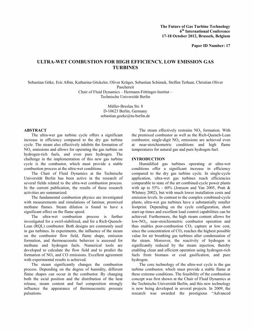
Measurement and simulation of burning velocity
Initial experiments on the small-scale combustion
flame test rig are conducted to investigate the influence of
steam on the fundamental flame characteristics. The
measurements are conducted with two different flame
configurations, using methane as fuel. The laminar flame
speed is investigated with a prismatic Bunsen flame
stabilized at the nozzle outlet. Figure 3 shows typical
images of this flame type. The second configuration is a
slightly turbulent V-flame attached to a tungsten rod with a
diameter of ø1.5mm. The measurements are conducted for
various steam contents, equivalence ratios, and
temperature of the unburnt gas. The results are presented in
detail in Albin et al. (2012).
1.77m/s
= 2.5%
1.77m/s
= 10%
1.10m/s
= 20%
0.58m/s
= 25%
Figure 3: Typical prismatic flames for various degree of
humidity.
The burning velocity (mean consumption speed) is
extracted from pictures of OH* chemiluminescence using
an area-based method for the Bunsen flames, and an angle-
based method for the V-flames. The laminar flame speed is
also derived from one-dimension calculations with Cantera
(Goodwin, 2003), using GRI-Mech 3.0 (Smith et al., 2000)
and the reaction mechanism by Konnov (Konnov, 2000).
The calculated laminar flame speed is scaled to the slightly
turbulent conditions of the experiments by assuming a
constant wrinkling ratio (Warnatz, 2006).
The measured and calculated flame speeds are
presented in Figure 4. Flames up to 25% of steam in the air
could be stabilized. The slightly turbulent V-flame has a
higher flame speed, and can be sustained over a wider
range of equivalence ratios and steam contents compared
to the laminar Bunsen flame. The influence of equivalence
ratio and steam content in the simulation results is
confirmed by the experimental data.
The mean consumption velocity is also compared to
previous experimental data from literature for
stoichiometric conditions at 480K (Figure 5). The
influence of the steam on the relative flame speed is
confirmed in the current study.
Figure 5: Measured consumption speeds are compared to
previous measurements and results of 1D adiabatic laminar
flame simulation (stoichiometric CH4/air flames at 480K).
These measurements form the basis for the validation
of Direct Numerical Simulations (DNS) with simple and
complex chemistry. These simulations provide a detailed
insight into the chemical effect of the steam, and about the
effect of stretch and turbulence on the local burning
velocity at wet conditions.
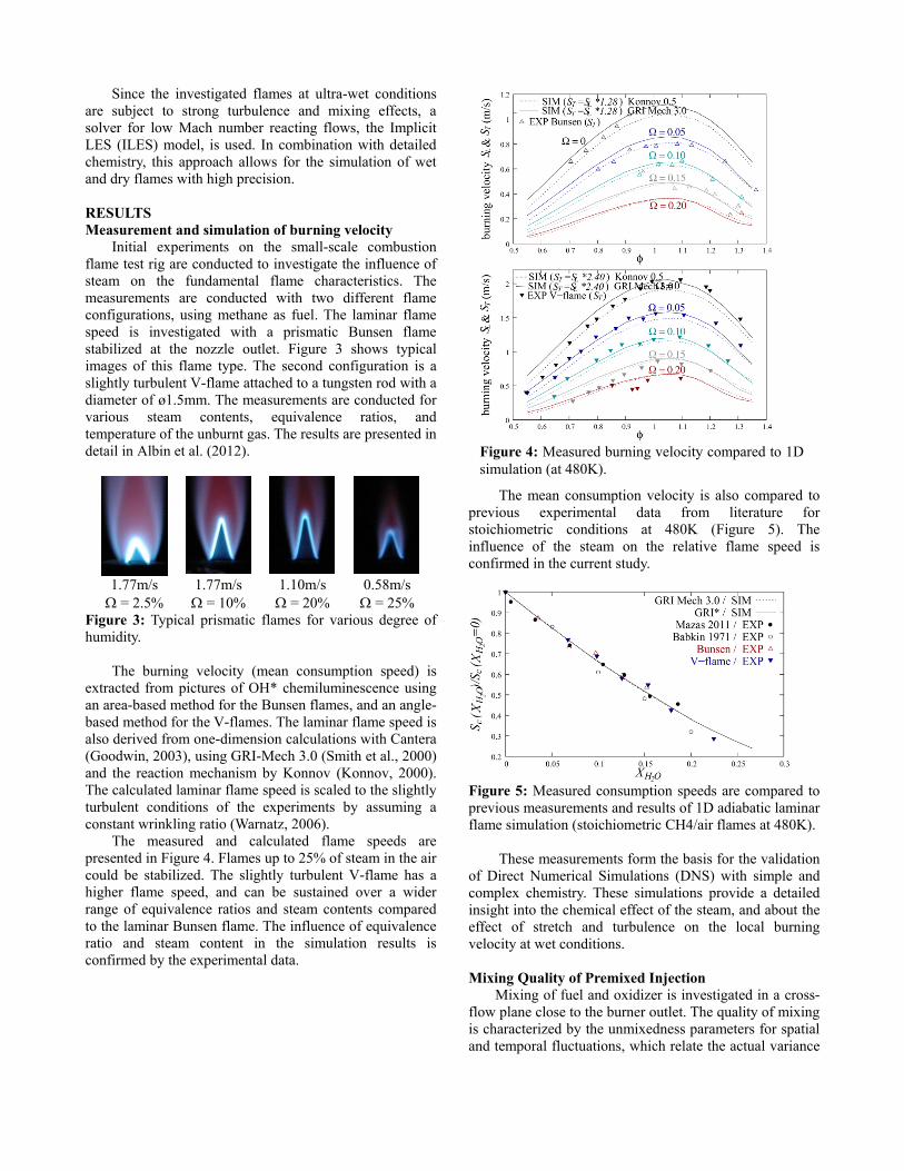
Mixing Quality of Premixed Injection
Mixing of fuel and oxidizer is investigated in a cross-
flow plane close to the burner outlet. The quality of mixing
is characterized by the unmixedness parameters for spatial
and temporal fluctuations, which relate the actual variance
Figure 4: Measured burning velocity compared to 1D
simulation (at 480K).
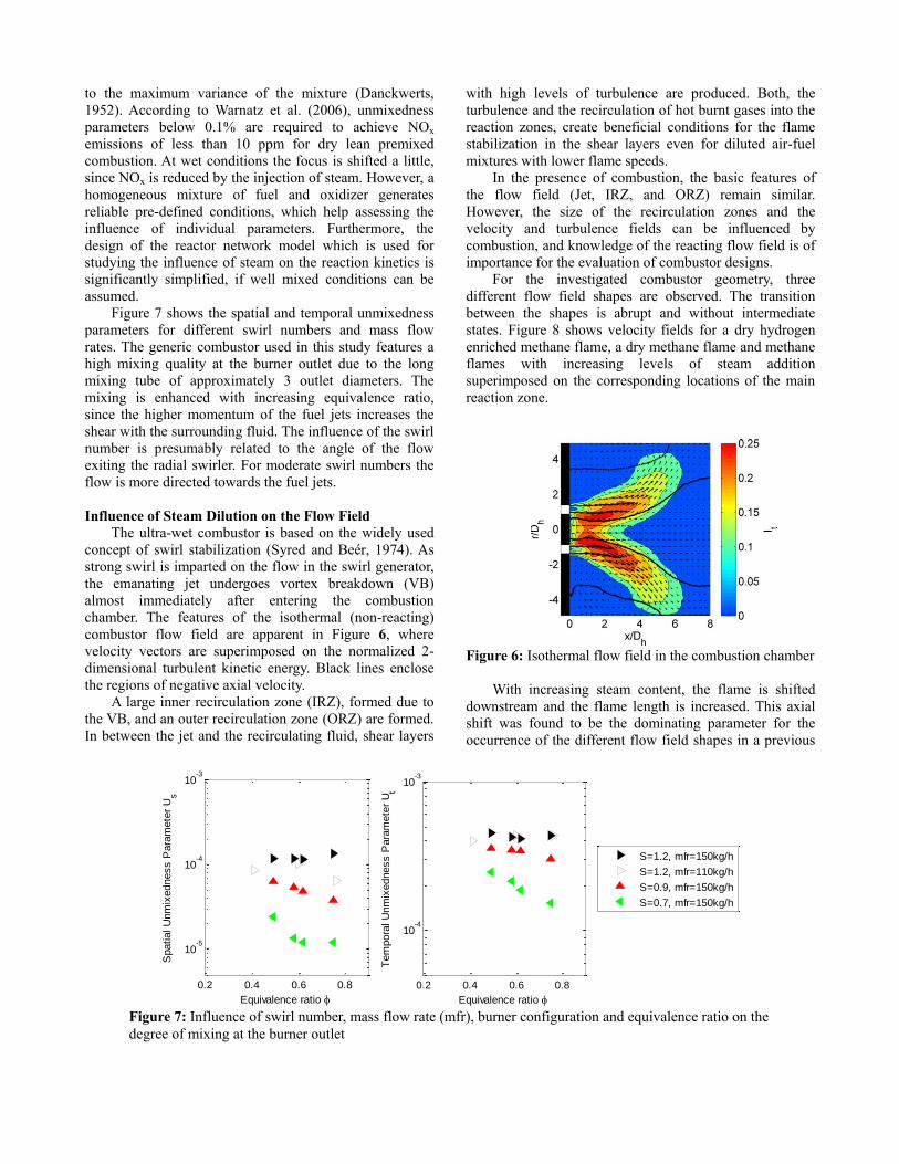
Figure 7: Influence of swirl number, mass flow rate (mfr), burner configuration and equivalence ratio on the
degree of mixing at the burner outlet
0.2 0.4 0.6 0.8
10-5
10-4
10-3
Equivalence ratio
Spatial U
nm
ixedness P
ara
mete
r U
s
S=1.2, mfr=150kg/h
S=1.2, mfr=110kg/h
S=0.9, mfr=150kg/h
S=0.7, mfr=150kg/h
0.2 0.4 0.6 0.8
10-4
10-3
Equivalence ratio
Tem
pora
l U
nm
ixedness P
ara
mete
r U
t
S=1.2, mfr=150kg/h
S=1.2, mfr=110kg/h
S=0.9, mfr=150kg/h
S=0.7, mfr=150kg/h
to the maximum variance of the mixture (Danckwerts,
1952). According to Warnatz et al. (2006), unmixedness
parameters below 0.1% are required to achieve NOx
emissions of less than 10 ppm for dry lean premixed
combustion. At wet conditions the focus is shifted a little,
since NOx is reduced by the injection of steam. However, a
homogeneous mixture of fuel and oxidizer generates
reliable pre-defined conditions, which help assessing the
influence of individual parameters. Furthermore, the
design of the reactor network model which is used for
studying the influence of steam on the reaction kinetics is
significantly simplified, if well mixed conditions can be
assumed.
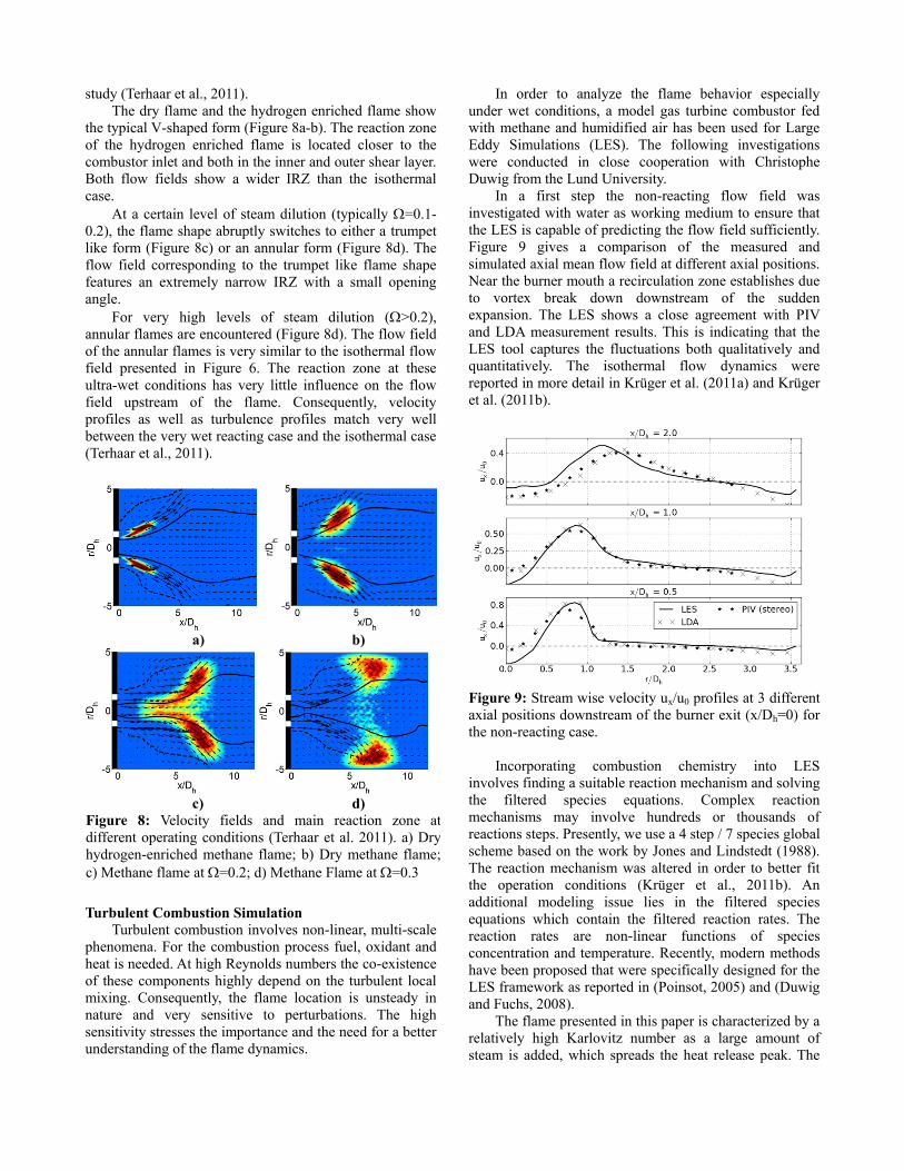
Figure 7 shows the spatial and temporal unmixedness
parameters for different swirl numbers and mass flow
rates. The generic combustor used in this study features a
high mixing quality at the burner outlet due to the long
mixing tube of approximately 3 outlet diameters. The
mixing is enhanced with increasing equivalence ratio,
since the higher momentum of the fuel jets increases the
shear with the surrounding fluid. The influence of the swirl
number is presumably related to the angle of the flow
exiting the radial swirler. For moderate swirl numbers the
flow is more directed towards the fuel jets.
Influence of Steam Dilution on the Flow Field
The ultra-wet combustor is based on the widely used
concept of swirl stabilization (Syred and Beér, 1974). As
strong swirl is imparted on the flow in the swirl generator,
the emanating jet undergoes vortex breakdown (VB)
almost immediately after entering the combustion
chamber. The features of the isothermal (non-reacting)
combustor flow field are apparent in Figure 6, where
velocity vectors are superimposed on the normalized 2-
dimensional turbulent kinetic energy. Black lines enclose
the regions of negative axial velocity.
A large inner recirculation zone (IRZ), formed due to
the VB, and an outer recirculation zone (ORZ) are formed.
In between the jet and the recirculating fluid, shear layers
with high levels of turbulence are produced. Both, the
turbulence and the recirculation of hot burnt gases into the
reaction zones, create beneficial conditions for the flame
stabilization in the shear layers even for diluted air-fuel
mixtures with lower flame speeds.
In the presence of combustion, the basic features of
the flow field (Jet, IRZ, and ORZ) remain similar.
However, the size of the recirculation zones and the
velocity and turbulence fields can be influenced by
combustion, and knowledge of the reacting flow field is of
importance for the evaluation of combustor designs.
For the investigated combustor geometry, three
different flow field shapes are observed. The transition
between the shapes is abrupt and without intermediate
states. Figure 8 shows velocity fields for a dry hydrogen
enriched methane flame, a dry methane flame and methane
flames with increasing levels of steam addition
superimposed on the corresponding locations of the main
reaction zone.
Figure 6: Isothermal flow field in the combustion chamber
With increasing steam content, the flame is shifted
downstream and the flame length is increased. This axial
shift was found to be the dominating parameter for the
occurrence of the different flow field shapes in a previous
study (Terhaar et al., 2011).
The dry flame and the hydrogen enriched flame show
the typical V-shaped form (Figure 8a-b). The reaction zone
of the hydrogen enriched flame is located closer to the
combustor inlet and both in the inner and outer shear layer.
Both flow fields show a wider IRZ than the isothermal
case.
At a certain level of steam dilution (typically =0.1-
0.2), the flame shape abruptly switches to either a trumpet
like form (Figure 8c) or an annular form (Figure 8d). The
flow field corresponding to the trumpet like flame shape
features an extremely narrow IRZ with a small opening
angle.
For very high levels of steam dilution (>0.2),
annular flames are encountered (Figure 8d). The flow field
of the annular flames is very similar to the isothermal flow
field presented in Figure 6. The reaction zone at these
ultra-wet conditions has very little influence on the flow
field upstream of the flame. Consequently, velocity
profiles as well as turbulence profiles match very well
between the very wet reacting case and the isothermal case
(Terhaar et al., 2011).
Turbulent Combustion Simulation
Turbulent combustion involves non-linear, multi-scale
phenomena. For the combustion process fuel, oxidant and
heat is needed. At high Reynolds numbers the co-existence
of these components highly depend on the turbulent local
mixing. Consequently, the flame location is unsteady in
nature and very sensitive to perturbations. The high
sensitivity stresses the importance and the need for a better
understanding of the flame dynamics.
In order to analyze the flame behavior especially
under wet conditions, a model gas turbine combustor fed
with methane and humidified air has been used for Large
Eddy Simulations (LES). The following investigations
were conducted in close cooperation with Christophe
Duwig from the Lund University.
In a first step the non-reacting flow field was
investigated with water as working medium to ensure that
the LES is capable of predicting the flow field sufficiently.
Figure 9 gives a comparison of the measured and
simulated axial mean flow field at different axial positions.
Near the burner mouth a recirculation zone establishes due
to vortex break down downstream of the sudden
expansion. The LES shows a close agreement with PIV
and LDA measurement results. This is indicating that the
LES tool captures the fluctuations both qualitatively and
quantitatively. The isothermal flow dynamics were
reported in more detail in Krüger et al. (2011a) and Krüger
et al. (2011b).
Figure 9: Stream wise velocity ux/u0 profiles at 3 different
axial positions downstream of the burner exit (x/Dh=0) for
the non-reacting case.
Incorporating combustion chemistry into LES
involves finding a suitable reaction mechanism and solving
the filtered species equations. Complex reaction
mechanisms may involve hundreds or thousands of
reactions steps. Presently, we use a 4 step / 7 species global
scheme based on the work by Jones and Lindstedt (1988).
The reaction mechanism was altered in order to better fit
the operation conditions (Krüger et al., 2011b). An
additional modeling issue lies in the filtered species
equations which contain the filtered reaction rates. The
reaction rates are non-linear functions of species
concentration and temperature. Recently, modern methods
have been proposed that were specifically designed for the
LES framework as reported in (Poinsot, 2005) and (Duwig
and Fuchs, 2008).
The flame presented in this paper is characterized by a
relatively high Karlovitz number as a large amount of
steam is added, which spreads the heat release peak. The
a) b)
c) d)
Figure 8: Velocity fields and main reaction zone at
different operating conditions (Terhaar et al. 2011). a) Dry
hydrogen-enriched methane flame; b) Dry methane flame;
c) Methane flame at =0.2; d) Methane Flame at =0.3
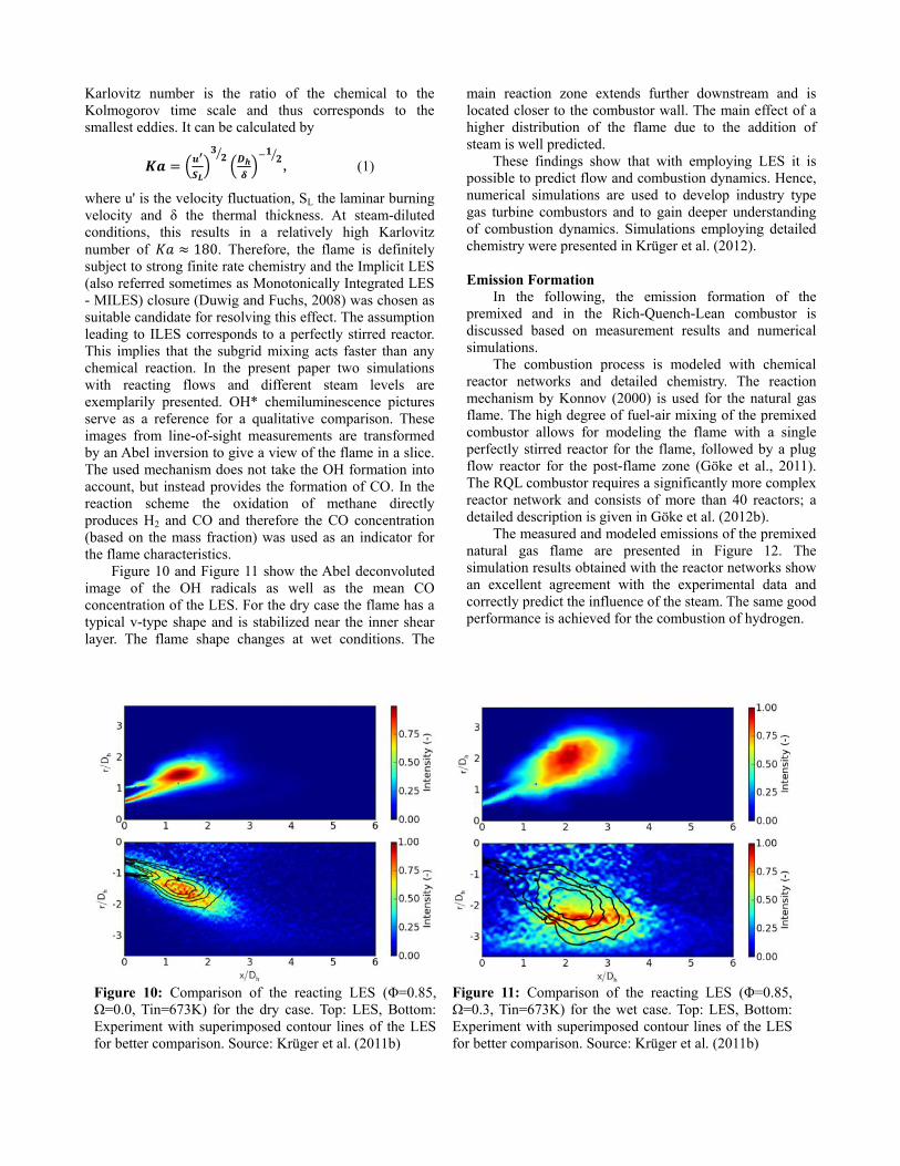
Figure 10: Comparison of the reacting LES (Φ=0.85,
Ω=0.0, Tin=673K) for the dry case. Top: LES, Bottom:
Experiment with superimposed contour lines of the LES
for better comparison. Source: Krüger et al. (2011b)
Figure 11: Comparison of the reacting LES (Φ=0.85,
Ω=0.3, Tin=673K) for the wet case. Top: LES, Bottom:
Experiment with superimposed contour lines of the LES
for better comparison. Source: Krüger et al. (2011b)
Karlovitz number is the ratio of the chemical to the
Kolmogorov time scale and thus corresponds to the
smallest eddies. It can be calculated by
𝑲𝒂 = (𝒖
𝑺 )𝟑
𝟐⁄
(𝑫
𝜹)−𝟏
𝟐⁄ , (1)
where u' is the velocity fluctuation, SL the laminar burning
velocity and δ the thermal thickness. At steam-diluted
conditions, this results in a relatively high Karlovitz
number of 𝐾𝑎 ≈ 180. Therefore, the flame is definitely
subject to strong finite rate chemistry and the Implicit LES
(also referred sometimes as Monotonically Integrated LES
- MILES) closure (Duwig and Fuchs, 2008) was chosen as
suitable candidate for resolving this effect. The assumption
leading to ILES corresponds to a perfectly stirred reactor.
This implies that the subgrid mixing acts faster than any
chemical reaction. In the present paper two simulations
with reacting flows and different steam levels are
exemplarily presented. OH* chemiluminescence pictures
serve as a reference for a qualitative comparison. These
images from line-of-sight measurements are transformed
by an Abel inversion to give a view of the flame in a slice.
The used mechanism does not take the OH formation into
account, but instead provides the formation of CO. In the
reaction scheme the oxidation of methane directly
produces H2 and CO and therefore the CO concentration
(based on the mass fraction) was used as an indicator for
the flame characteristics.
Figure 10 and Figure 11 show the Abel deconvoluted
image of the OH radicals as well as the mean CO
concentration of the LES. For the dry case the flame has a
typical v-type shape and is stabilized near the inner shear
layer. The flame shape changes at wet conditions. The
main reaction zone extends further downstream and is
located closer to the combustor wall. The main effect of a
higher distribution of the flame due to the addition of
steam is well predicted.
These findings show that with employing LES it is
possible to predict flow and combustion dynamics. Hence,
numerical simulations are used to develop industry type
gas turbine combustors and to gain deeper understanding
of combustion dynamics. Simulations employing detailed
chemistry were presented in Krüger et al. (2012).
Emission Formation
In the following, the emission formation of the
premixed and in the Rich-Quench-Lean combustor is
discussed based on measurement results and numerical
simulations.
The combustion process is modeled with chemical
reactor networks and detailed chemistry. The reaction
mechanism by Konnov (2000) is used for the natural gas
flame. The high degree of fuel-air mixing of the premixed
combustor allows for modeling the flame with a single
perfectly stirred reactor for the flame, followed by a plug
flow reactor for the post-flame zone (Göke et al., 2011).
The RQL combustor requires a significantly more complex
reactor network and consists of more than 40 reactors; a
detailed description is given in Göke et al. (2012b).
The measured and modeled emissions of the premixed
natural gas flame are presented in Figure 12. The
simulation results obtained with the reactor networks show
an excellent agreement with the experimental data and
correctly predict the influence of the steam. The same good
performance is achieved for the combustion of hydrogen.
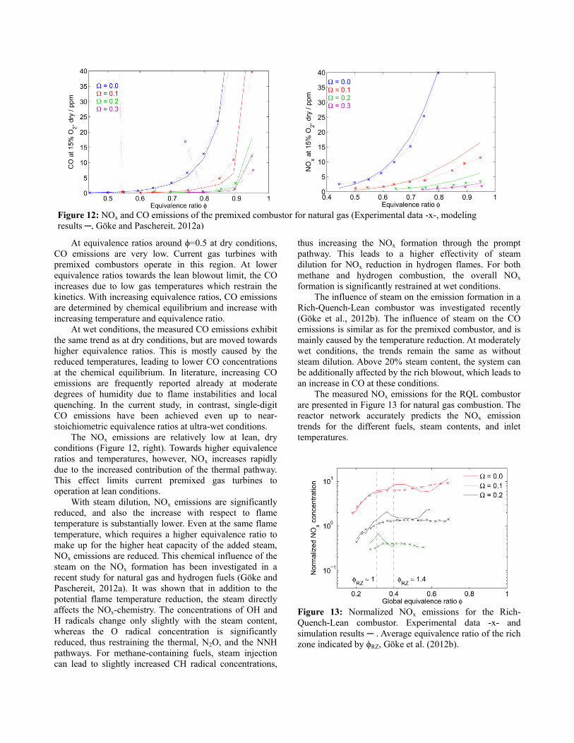
Figure 12: NOx and CO emissions of the premixed combustor for natural gas (Experimental data -x-, modeling
results , Göke and Paschereit, 2012a)
At equivalence ratios around ϕ=0.5 at dry conditions,
CO emissions are very low. Current gas turbines with
premixed combustors operate in this region. At lower
equivalence ratios towards the lean blowout limit, the CO
increases due to low gas temperatures which restrain the
kinetics. With increasing equivalence ratios, CO emissions
are determined by chemical equilibrium and increase with
increasing temperature and equivalence ratio.
At wet conditions, the measured CO emissions exhibit
the same trend as at dry conditions, but are moved towards
higher equivalence ratios. This is mostly caused by the
reduced temperatures, leading to lower CO concentrations
at the chemical equilibrium. In literature, increasing CO
emissions are frequently reported already at moderate
degrees of humidity due to flame instabilities and local
quenching. In the current study, in contrast, single-digit
CO emissions have been achieved even up to near-
stoichiometric equivalence ratios at ultra-wet conditions.
The NOx emissions are relatively low at lean, dry
conditions (Figure 12, right). Towards higher equivalence
ratios and temperatures, however, NOx increases rapidly
due to the increased contribution of the thermal pathway.
This effect limits current premixed gas turbines to
operation at lean conditions.
With steam dilution, NOx emissions are significantly
reduced, and also the increase with respect to flame
temperature is substantially lower. Even at the same flame
temperature, which requires a higher equivalence ratio to
make up for the higher heat capacity of the added steam,
NOx emissions are reduced. This chemical influence of the
steam on the NOx formation has been investigated in a
recent study for natural gas and hydrogen fuels (Göke and
Paschereit, 2012a). It was shown that in addition to the
potential flame temperature reduction, the steam directly
affects the NOx-chemistry. The concentrations of OH and
H radicals change only slightly with the steam content,
whereas the O radical concentration is significantly
reduced, thus restraining the thermal, N2O, and the NNH
pathways. For methane-containing fuels, steam injection
can lead to slightly increased CH radical concentrations,
thus increasing the NOx formation through the prompt
pathway. This leads to a higher effectivity of steam
dilution for NOx reduction in hydrogen flames. For both
methane and hydrogen combustion, the overall NOx
formation is significantly restrained at wet conditions.
The influence of steam on the emission formation in a
Rich-Quench-Lean combustor was investigated recently
(Göke et al., 2012b). The influence of steam on the CO
emissions is similar as for the premixed combustor, and is
mainly caused by the temperature reduction. At moderately
wet conditions, the trends remain the same as without
steam dilution. Above 20% steam content, the system can
be additionally affected by the rich blowout, which leads to
an increase in CO at these conditions.
The measured NOx emissions for the RQL combustor
are presented in Figure 13 for natural gas combustion. The
reactor network accurately predicts the NOx emission
trends for the different fuels, steam contents, and inlet
temperatures.
Figure 13: Normalized NOx emissions for the Rich-
Quench-Lean combustor. Experimental data -x- and
simulation results . Average equivalence ratio of the rich
zone indicated by ϕRZ, Göke et al. (2012b).
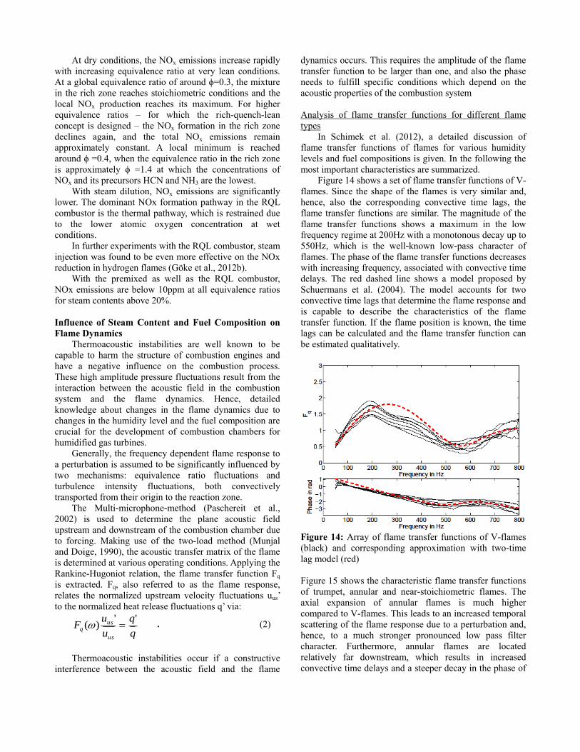
At dry conditions, the NOx emissions increase rapidly
with increasing equivalence ratio at very lean conditions.
At a global equivalence ratio of around ϕ=0.3, the mixture
in the rich zone reaches stoichiometric conditions and the
local NOx production reaches its maximum. For higher
equivalence ratios – for which the rich-quench-lean
concept is designed – the NOx formation in the rich zone
declines again, and the total NOx emissions remain
approximately constant. A local minimum is reached
around ϕ =0.4, when the equivalence ratio in the rich zone
is approximately ϕ =1.4 at which the concentrations of
NOx and its precursors HCN and NH3 are the lowest.
With steam dilution, NOx emissions are significantly
lower. The dominant NOx formation pathway in the RQL
combustor is the thermal pathway, which is restrained due
to the lower atomic oxygen concentration at wet
conditions.
In further experiments with the RQL combustor, steam
injection was found to be even more effective on the NOx
reduction in hydrogen flames (Göke et al., 2012b).
With the premixed as well as the RQL combustor,
NOx emissions are below 10ppm at all equivalence ratios
for steam contents above 20%.
Influence of Steam Content and Fuel Composition on
Flame Dynamics
Thermoacoustic instabilities are well known to be
capable to harm the structure of combustion engines and
have a negative influence on the combustion process.
These high amplitude pressure fluctuations result from the
interaction between the acoustic field in the combustion
system and the flame dynamics. Hence, detailed
knowledge about changes in the flame dynamics due to
changes in the humidity level and the fuel composition are
crucial for the development of combustion chambers for
humidified gas turbines.
Generally, the frequency dependent flame response to
a perturbation is assumed to be significantly influenced by
two mechanisms: equivalence ratio fluctuations and
turbulence intensity fluctuations, both convectively
transported from their origin to the reaction zone.
The Multi-microphone-method (Paschereit et al.,
2002) is used to determine the plane acoustic field
upstream and downstream of the combustion chamber due
to forcing. Making use of the two-load method (Munjal
and Doige, 1990), the acoustic transfer matrix of the flame
is determined at various operating conditions. Applying the
Rankine-Hugoniot relation, the flame transfer function Fq
is extracted. Fq, also referred to as the flame response,
relates the normalized upstream velocity fluctuations uus’
to the normalized heat release fluctuations q’ via:
q
q
u
uF
us
usq
'')( . (2)
Thermoacoustic instabilities occur if a constructive
interference between the acoustic field and the flame
dynamics occurs. This requires the amplitude of the flame
transfer function to be larger than one, and also the phase
needs to fulfill specific conditions which depend on the
acoustic properties of the combustion system
Analysis of flame transfer functions for different flame
types
In Schimek et al. (2012), a detailed discussion of
flame transfer functions of flames for various humidity
levels and fuel compositions is given. In the following the
most important characteristics are summarized.
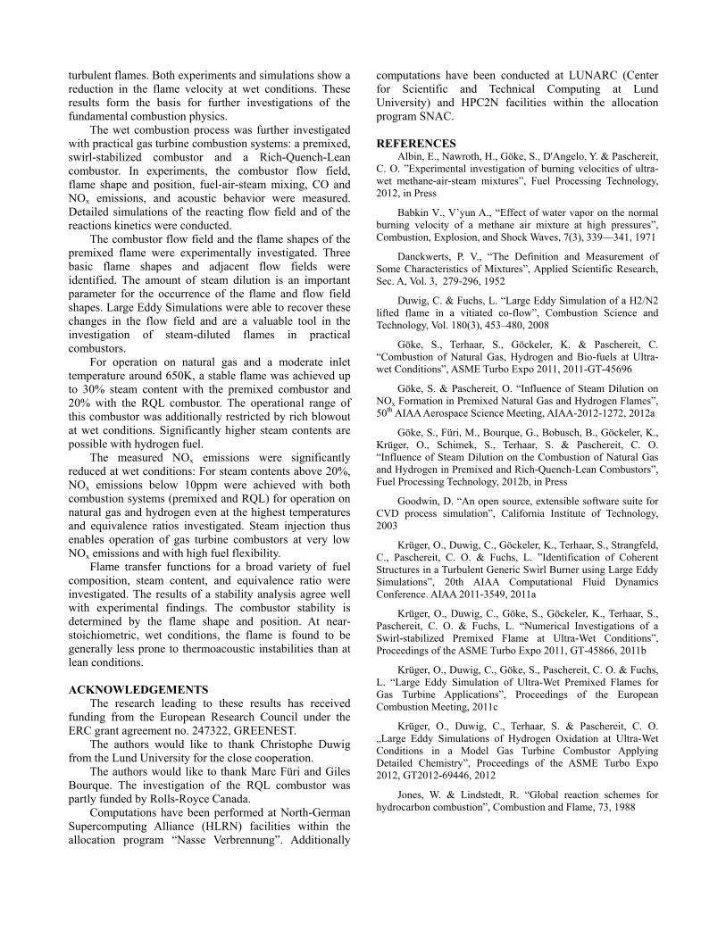
Figure 14 shows a set of flame transfer functions of V-
flames. Since the shape of the flames is very similar and,
hence, also the corresponding convective time lags, the
flame transfer functions are similar. The magnitude of the
flame transfer functions shows a maximum in the low
frequency regime at 200Hz with a monotonous decay up to
550Hz, which is the well-known low-pass character of
flames. The phase of the flame transfer functions decreases
with increasing frequency, associated with convective time
delays. The red dashed line shows a model proposed by
Schuermans et al. (2004). The model accounts for two
convective time lags that determine the flame response and
is capable to describe the characteristics of the flame
transfer function. If the flame position is known, the time
lags can be calculated and the flame transfer function can
be estimated qualitatively.
Figure 14: Array of flame transfer functions of V-flames
(black) and corresponding approximation with two-time
lag model (red)
Figure 15 shows the characteristic flame transfer functions
of trumpet, annular and near-stoichiometric flames. The
axial expansion of annular flames is much higher
compared to V-flames. This leads to an increased temporal
scattering of the flame response due to a perturbation and,
hence, to a much stronger pronounced low pass filter
character. Furthermore, annular flames are located
relatively far downstream, which results in increased
convective time delays and a steeper decay in the phase of

the flame transfer function. The latter also holds true for
flame transfer functions of trumpet flames. For this flame
type, the magnitude is approximately constant over a wide
frequency range (100-500Hz) followed by a strong decay.
Figure 15: Characteristic flame transfer functions of
trumpet, annular and near-stoichiometric flames
For near-stoichiometric flames, the amplitude of the flame
transfer function is approximately unity over the entire
frequency range investigated, and is independent of the
steam content and fuel composition. Since the flame is the
only source of acoustic energy in a thermo acoustic
system, near-stoichiometric flames are thus unlikely to
cause thermo acoustic instabilities. These flames are
attached to the combustion chamber inlet. The decay of the
phase is comparable to that of other V-flames.
Stability Analysis
The prediction of system stability is one of the major
goals of thermoacoustic investigations. In the following,
the experimental acoustic downstream boundary condition
is changed in order to obtain stable as well as unstable
operating conditions. A linear network model of the system
(Lieuwen, 2005), which includes the previously measured
flame transfer functions, is designed. Further details on the
modeling techniques and the obtained results can be found
in Schimek et al. (2011).
Solving the dispersion relation of the linear network
model, the complex system eigenvalues are obtained
numerically. The real part of the latter represents the
angular resonance frequencies of the system and the
imaginary part, the damping rate. A negative imaginary
part corresponds to exponential growth in time and, thus,
to self-excited thermoacoustic instability.
Figure 16 shows the amplitude of the first resonance
frequency in the measured acoustic spectra and the
corresponding damping predicted from the stability
analysis for all operating conditions investigated. With
increasing damping the measured oscillation amplitude
decreases and vice versa. Applying linear modeling
techniques generally allows for predictions stability of a
system, but not about the resulting oscillation amplitudes.
Figure 16: Measured amplitude of the first resonance
frequency of the system plotted versus predicted damping
from stability analysis.
Several operating conditions for natural gas at humid
conditions are marked as partially unstable. At these
conditions, pressure oscillations alter between stable and
unstable modes while the operating conditions are kept
constant. Figure 17 shows an example of a time trace of a
partially unstable operating condition. The ratio between
resident time in stable and unstable mode strongly depends
on the operating condition. A significant change in the
flame shape is observed when the flame changes between
stable and unstable. In the unstable case, the heat release
region becomes more compact, which might be due to an
increased turbulence level, and moves closer to the
combustor axis. All partially unstable operating conditions
correspond to lifted flames (i.e. annular or trumpet- flame
type), which are relatively weakly anchored to the
combustor geometry.
Figure 17: Time trace of combustor pressure changing
between stable and unstable mode
CONCLUSIONS
The steam-diluted combustion of natural gas and
hydrogen is investigated at the Chair of Fluid Dynamics,
and the main findings were presented in the current
publication.
The fundamental flame characteristics were
investigated with small-scale, laminar and slightly
turbulent flames. Both experiments and simulations show a
reduction in the flame velocity at wet conditions. These
results form the basis for further investigations of the
fundamental combustion physics.
The wet combustion process was further investigated
with practical gas turbine combustion systems: a premixed,
swirl-stabilized combustor and a Rich-Quench-Lean
combustor. In experiments, the combustor flow field,
flame shape and position, fuel-air-steam mixing, CO and
NOx emissions, and acoustic behavior were measured.
Detailed simulations of the reacting flow field and of the
reactions kinetics were conducted.
The combustor flow field and the flame shapes of the
premixed flame were experimentally investigated. Three
basic flame shapes and adjacent flow fields were
identified. The amount of steam dilution is an important
parameter for the occurrence of the flame and flow field
shapes. Large Eddy Simulations were able to recover these
changes in the flow field and are a valuable tool in the
investigation of steam-diluted flames in practical
combustors.
For operation on natural gas and a moderate inlet
temperature around 650K, a stable flame was achieved up
to 30% steam content with the premixed combustor and
20% with the RQL combustor. The operational range of
this combustor was additionally restricted by rich blowout
at wet conditions. Significantly higher steam contents are
possible with hydrogen fuel.
The measured NOx emissions were significantly
reduced at wet conditions: For steam contents above 20%,
NOx emissions below 10ppm were achieved with both
combustion systems (premixed and RQL) for operation on
natural gas and hydrogen even at the highest temperatures
and equivalence ratios investigated. Steam injection thus
enables operation of gas turbine combustors at very low
NOx emissions and with high fuel flexibility.
Flame transfer functions for a broad variety of fuel
composition, steam content, and equivalence ratio were
investigated. The results of a stability analysis agree well
with experimental findings. The combustor stability is
determined by the flame shape and position. At near-
stoichiometric, wet conditions, the flame is found to be
generally less prone to thermoacoustic instabilities than at
lean conditions.
ACKNOWLEDGEMENTS
The research leading to these results has received
funding from the European Research Council under the
ERC grant agreement no. 247322, GREENEST.
The authors would like to thank Christophe Duwig
from the Lund University for the close cooperation.
The authors would like to thank Marc Füri and Giles
Bourque. The investigation of the RQL combustor was
partly funded by Rolls-Royce Canada.
Computations have been performed at North-German
Supercomputing Alliance (HLRN) facilities within the
allocation program “Nasse Verbrennung”. Additionally
computations have been conducted at LUNARC (Center
for Scientific and Technical Computing at Lund
University) and HPC2N facilities within the allocation
program SNAC.
REFERENCES Albin, E., Nawroth, H., Göke, S., D'Angelo, Y. & Paschereit,
C. O. ”Experimental investigation of burning velocities of ultra-
wet methane-air-steam mixtures”, Fuel Processing Technology,
2012, in Press
Babkin V., V’yun A., “Effect of water vapor on the normal
burning velocity of a methane air mixture at high pressures”,
Combustion, Explosion, and Shock Waves, 7(3), 339—341, 1971
Danckwerts, P. V., “The Definition and Measurement of
Some Characteristics of Mixtures”, Applied Scientific Research,
Sec. A, Vol. 3, 279-296, 1952
Duwig, C. & Fuchs, L. “Large Eddy Simulation of a H2/N2
lifted flame in a vitiated co-flow”, Combustion Science and
Technology, Vol. 180(3), 453–480, 2008
Göke, S., Terhaar, S., Göckeler, K. & Paschereit, C.
“Combustion of Natural Gas, Hydrogen and Bio-fuels at Ultra-
wet Conditions”, ASME Turbo Expo 2011, 2011-GT-45696
Göke, S. & Paschereit, O. “Influence of Steam Dilution on
NOx Formation in Premixed Natural Gas and Hydrogen Flames”,
50th AIAA Aerospace Science Meeting, AIAA-2012-1272, 2012a
Göke, S., Füri, M., Bourque, G., Bobusch, B., Göckeler, K.,
Krüger, O., Schimek, S., Terhaar, S. & Paschereit, C. O.
“Influence of Steam Dilution on the Combustion of Natural Gas
and Hydrogen in Premixed and Rich-Quench-Lean Combustors”,
Fuel Processing Technology, 2012b, in Press
Goodwin, D. “An open source, extensible software suite for
CVD process simulation”, California Institute of Technology,
2003
Krüger, O., Duwig, C., Göckeler, K., Terhaar, S., Strangfeld,
C., Paschereit, C. O. & Fuchs, L. ”Identification of Coherent
Structures in a Turbulent Generic Swirl Burner using Large Eddy
Simulations”, 20th AIAA Computational Fluid Dynamics
Conference. AIAA 2011-3549, 2011a
Krüger, O., Duwig, C., Göke, S., Göckeler, K., Terhaar, S.,
Paschereit, C. O. & Fuchs, L. “Numerical Investigations of a
Swirl-stabilized Premixed Flame at Ultra-Wet Conditions”,
Proceedings of the ASME Turbo Expo 2011, GT-45866, 2011b
Krüger, O., Duwig, C., Göke, S., Paschereit, C. O. & Fuchs,
L. “Large Eddy Simulation of Ultra-Wet Premixed Flames for
Gas Turbine Applications”, Proceedings of the European
Combustion Meeting, 2011c
Krüger, O., Duwig, C., Terhaar, S. & Paschereit, C. O.
„Large Eddy Simulations of Hydrogen Oxidation at Ultra-Wet
Conditions in a Model Gas Turbine Combustor Applying
Detailed Chemistry”, Proceedings of the ASME Turbo Expo
2012, GT2012-69446, 2012
Jones, W. & Lindstedt, R. “Global reaction schemes for
hydrocarbon combustion”, Combustion and Flame, 73, 1988

Jonsson, M. & Yan, J. “Humidified gas turbine - a review of
proposed and implemented cycles” Energy, 2005, 30, 1013 –
1078
Konnov, A. “Development and validation of a detailed
reaction mechanism for the combustion of small hydrocarbons”,
28th Symposium (International) on Combustion, 2000, 317
Mazas A., Fiorina B., Lacoste D., Schuller T., 2011.
“Effects of water vapor addition on the laminar burning velocity
of methane oxygen enriched methane flames”, Combustion and
Flame, 158(12), pp. 2428--2440.
Munjal, M. L., & Doige, A. G., 1990. “Theory of a two
source-location method for direct experimental evaluation of the
four-pole parameters of an aeroacoustic element”. Journal of
Sound and Vibration, 141, pp. 323–333.
Lieuwen, T. C., & Yang, V., eds., 2005. Combustion
Instabilities in Gas Turbine Engines. Progress in Astronautics and
Aeronautics vol. 210. AIAA, Inc., Reston, VA.
Paschereit, C. O., Schuermans, B., Polifke, W. & Mattson,
O., 2002. “Measurement of transfer matrices and source terms of
premixed flames”, Journal of Engineering for Gas Turbines and
Power, 124(2), pp. 239–247.
Poinsot, T. & Veynante, D. “Theoretical and Numerical
Combustion”, R.T. Edwards, 2nd edition, 2005.
Pratt & Whitney, “Humid air turbine cycle technology
development program – Final Report”, National Energy
Technology Center, U.S. Department of Energy, 2002
Schimek, S., Göke, S., Schrödinger, C. & Paschereit, C.,
2012. “Analysis of flame transfer functions for blends of CH4
and H2 at different humidity levels”, In 50th AIAA Aerospace
Science Meeting, AIAA-2012-0932.
Schimek, S., Göke, S., Schrödinger, C. & Paschereit, C.,
2012. “Flame transfer function measurements with CH4 and H2
fuel mixtures at ultra-wet conditions in a swirl stabilized
premixed combustor”, In Proceedings of ASME TurboExpo
2012: Power for Land, Sea and Air, June 11 - 15, Copenhagen,
Denmark. GT2012-69788.
Schuermans, B., Bellucci, V., Guethe, F., Meili, F., Flohr, P.,
& Paschereit, C. O., 2004, “A detailed analysis of thermoacoustic
interaction mechanisms in a turbulent premixed flame”, ASME
Paper GT2004-53831.
Smith, G., Golden, D., Frenklach, M., Moriarty, N.,
Eiteneer, B., Goldenberg, M., Bowman, C., Hanson, R., Song, S.,
Gardiner, W., Lissianski, V., & Qin, Z., “GRI-Mech 3.0”,
http://www.me.berkeley.edu/gri_mech/
Terhaar, S., Göckeler, K., Schimek, S., Göke, S. &
Paschereit, C., “Non-Reacting and Reacting Flow in a Swirl-
Stabilized Burner for Ultra-Wet Combustion”, Proceedings of
41st AIAA Fluid Dynamics Conference and Exhibit 27 - 30 June
2011, Honolulu, Hawaii, 2011
Warnatz, J., Maas, U. & Dibble, R. “Combustion - physical
and chemical fundamentals, modeling and simulation,
experiments, pollutant formation”, Springer Berlin Heidelberg
New York, 4th edition, 2006. ISBN 3-540-25992-9.


