Ultra-Low Latency (ULL) Networks: The IEEE TSN and IETF ...
58
88 IEEE COMMUNICATIONS SURVEYS & TUTORIALS, VOL. 21, NO. 1, FIRST QUARTER 2019 Ultra-Low Latency (ULL) Networks: The IEEE TSN and IETF DetNet Standards and Related 5G ULL Research Ahmed Nasrallah, Akhilesh S. Thyagaturu, Ziyad Alharbi, Cuixiang Wang, Xing Shao, Martin Reisslein , Fellow, IEEE, and Hesham ElBakoury Abstract—Many network applications, e.g., industrial control, demand ultra-low latency (ULL). However, traditional packet networks can only reduce the end-to-end latencies to the order of tens of milliseconds. The IEEE 802.1 time sensitive networking (TSN) standard and related research studies have sought to pro- vide link layer support for ULL networking, while the emerging IETF deterministic networking (DetNet) standards seek to pro- vide the complementary network layer ULL support. This paper provides an up-to-date comprehensive survey of the IEEE TSN and IETF DetNet standards and the related research studies. The survey of these standards and research studies is organized according to the main categories of flow concept, flow synchro- nization, flow management, flow control, and flow integrity. ULL networking mechanisms play a critical role in the emerging fifth generation (5G) network access chain from wireless devices via access, backhaul, and core networks. We survey the studies that specifically target the support of ULL in 5G networks, with the main categories of fronthaul, backhaul, and network manage- ment. Throughout, we identify the pitfalls and limitations of the existing standards and research studies. This survey can thus serve as a basis for the development of standards enhance- ments and future ULL research studies that address the identified pitfalls and limitations. Index Terms—Deterministic networking (DetNet), preemption, time-sensitive networking (TSN), time synchronization, ultra-low delay. I. I NTRODUCTION A. Motivation T RADITIONAL networks which provide end-to-end con- nectivity to the users have only been successful in reducing the operating end-to-end latencies to the order of Manuscript received March 10, 2018; revised July 22, 2018; accepted September 1, 2018. Date of publication September 10, 2018; date of cur- rent version February 22, 2019. The work of C. Wang was supported by the Overseas Training Program of the Yancheng Institute of Technology. The work of X. Shao was supported by the Jiangsu Provincial Government Scholarship for Overseas Learning. (Corresponding author: Martin Reisslein.) A. Nasrallah, A. S. Thyagaturu, Z. Alharbi, and M. Reisslein are with the School of Electrical, Computer, and Energy Engineering, Arizona State University, Tempe, AZ 85287 USA (e-mail: [email protected]; [email protected]; [email protected]; [email protected]). C. Wang and X. Shao were with the Department of Internet of Things Engineering, Yancheng Institute of Technology, Yancheng 224051, China. They are now with the School of Electrical, Computer, and Energy Engineering, Arizona State University, Tempe, AZ 85287 USA (e-mail: [email protected]; [email protected]). H. ElBakoury is with the Network Technology Department, Futurewei Technologies Inc., Santa Clara, CA 95050 USA (e-mail: [email protected]). Digital Object Identifier 10.1109/COMST.2018.2869350 tens of milliseconds. However, present and future applications demand Ultra-Low Latency (ULL). For instance, the end-to- end latencies should be on the order of a few microseconds to a few milliseconds for industrial applications [1], around 1 millisecond for the tactile Internet [2], [3], and on the order of 100 microseconds for the one-way fronthaul in wireless cellular networks. For example, critical healthcare applica- tions, e.g., for tele-surgery, and transportation applications [4] require near real-time connectivity. Throughput requirements largely dependent on the application needs, which may vary widely from small amounts of IoT data to large exchanges of media data transfers to and from the cloud (or the fog to reduce latency) [5]. Additionally, autonomous automo- tive vehicles [6], augmented and virtual reality (AR/VR), as well as robotic applications, which are essential for Industrial IoT (IIoT), may require both high data rates as well as ULL [7]–[10]. The high data rates may be required for trans- porting video feeds from cameras that are used to control vehicles and robots [11]. Therefore, in such heterogeneous environments and applications, a dedicated mechanism to uni- versally accommodate a diverse range of ULL requirements would be very helpful [12]. B. Contributions and Organization of This Survey This article provides a comprehensive up-to-date survey of standards and research studies addressing networking mecha- nisms for ULL applications. Section III covers the IEEE TSN standards that have grown out of the AVB standards and focus primarily on the link layer, while Section IV covers the ULL research studies related to TSN. Section V covers the Internet Engineering Task Force (IETF) Deterministic Networking (DetNet) standards developments, while Section VI covers the ULL research studies related to DetNet. This sequence of the section on standards followed by the section on related research studies is inspired by the temporal sequence of the development of the ULL field, where standard development has typically preceded research studies. A large portion of the ULL applications will likely involve wireless communications, whereby the fifth generation (5G) wireless systems will play a prominent role. In particular, the emerging tactile Internet paradigm with end-to-end tar- get latencies below 1 ms is tightly coupled to the ongoing 5G developments [5], [13]–[16]. The support of 5G wireless 1553-877X c 2018 IEEE. Personal use is permitted, but republication/redistribution requires IEEE permission. See http://www.ieee.org/publications_standards/publications/rights/index.html for more information.
Transcript of Ultra-Low Latency (ULL) Networks: The IEEE TSN and IETF ...
88 IEEE COMMUNICATIONS SURVEYS & TUTORIALS, VOL. 21, NO. 1, FIRST QUARTER 2019
Ultra-Low Latency (ULL) Networks: The IEEETSN and IETF DetNet Standards and Related
5G ULL ResearchAhmed Nasrallah, Akhilesh S. Thyagaturu, Ziyad Alharbi, Cuixiang Wang, Xing Shao,
Martin Reisslein , Fellow, IEEE, and Hesham ElBakoury
Abstract—Many network applications, e.g., industrial control,demand ultra-low latency (ULL). However, traditional packetnetworks can only reduce the end-to-end latencies to the orderof tens of milliseconds. The IEEE 802.1 time sensitive networking(TSN) standard and related research studies have sought to pro-vide link layer support for ULL networking, while the emergingIETF deterministic networking (DetNet) standards seek to pro-vide the complementary network layer ULL support. This paperprovides an up-to-date comprehensive survey of the IEEE TSNand IETF DetNet standards and the related research studies.The survey of these standards and research studies is organizedaccording to the main categories of flow concept, flow synchro-nization, flow management, flow control, and flow integrity. ULLnetworking mechanisms play a critical role in the emerging fifthgeneration (5G) network access chain from wireless devices viaaccess, backhaul, and core networks. We survey the studies thatspecifically target the support of ULL in 5G networks, with themain categories of fronthaul, backhaul, and network manage-ment. Throughout, we identify the pitfalls and limitations ofthe existing standards and research studies. This survey canthus serve as a basis for the development of standards enhance-ments and future ULL research studies that address the identifiedpitfalls and limitations.
Index Terms—Deterministic networking (DetNet), preemption,time-sensitive networking (TSN), time synchronization, ultra-lowdelay.
I. INTRODUCTION
A. Motivation
TRADITIONAL networks which provide end-to-end con-nectivity to the users have only been successful in
reducing the operating end-to-end latencies to the order of
Manuscript received March 10, 2018; revised July 22, 2018; acceptedSeptember 1, 2018. Date of publication September 10, 2018; date of cur-rent version February 22, 2019. The work of C. Wang was supported by theOverseas Training Program of the Yancheng Institute of Technology. The workof X. Shao was supported by the Jiangsu Provincial Government Scholarshipfor Overseas Learning. (Corresponding author: Martin Reisslein.)
A. Nasrallah, A. S. Thyagaturu, Z. Alharbi, and M. Reisslein are withthe School of Electrical, Computer, and Energy Engineering, ArizonaState University, Tempe, AZ 85287 USA (e-mail: [email protected];[email protected]; [email protected]; [email protected]).
C. Wang and X. Shao were with the Department of Internet of ThingsEngineering, Yancheng Institute of Technology, Yancheng 224051, China.They are now with the School of Electrical, Computer, and EnergyEngineering, Arizona State University, Tempe, AZ 85287 USA (e-mail:[email protected]; [email protected]).
H. ElBakoury is with the Network Technology Department,Futurewei Technologies Inc., Santa Clara, CA 95050 USA (e-mail:[email protected]).
Digital Object Identifier 10.1109/COMST.2018.2869350
tens of milliseconds. However, present and future applicationsdemand Ultra-Low Latency (ULL). For instance, the end-to-end latencies should be on the order of a few microsecondsto a few milliseconds for industrial applications [1], around1 millisecond for the tactile Internet [2], [3], and on the orderof 100 microseconds for the one-way fronthaul in wirelesscellular networks. For example, critical healthcare applica-tions, e.g., for tele-surgery, and transportation applications [4]require near real-time connectivity. Throughput requirementslargely dependent on the application needs, which may varywidely from small amounts of IoT data to large exchangesof media data transfers to and from the cloud (or the fogto reduce latency) [5]. Additionally, autonomous automo-tive vehicles [6], augmented and virtual reality (AR/VR), aswell as robotic applications, which are essential for IndustrialIoT (IIoT), may require both high data rates as well asULL [7]–[10]. The high data rates may be required for trans-porting video feeds from cameras that are used to controlvehicles and robots [11]. Therefore, in such heterogeneousenvironments and applications, a dedicated mechanism to uni-versally accommodate a diverse range of ULL requirementswould be very helpful [12].
B. Contributions and Organization of This Survey
This article provides a comprehensive up-to-date survey ofstandards and research studies addressing networking mecha-nisms for ULL applications. Section III covers the IEEE TSNstandards that have grown out of the AVB standards and focusprimarily on the link layer, while Section IV covers the ULLresearch studies related to TSN. Section V covers the InternetEngineering Task Force (IETF) Deterministic Networking(DetNet) standards developments, while Section VI coversthe ULL research studies related to DetNet. This sequenceof the section on standards followed by the section on relatedresearch studies is inspired by the temporal sequence of thedevelopment of the ULL field, where standard developmenthas typically preceded research studies.
A large portion of the ULL applications will likely involvewireless communications, whereby the fifth generation (5G)wireless systems will play a prominent role. In particular,the emerging tactile Internet paradigm with end-to-end tar-get latencies below 1 ms is tightly coupled to the ongoing5G developments [5], [13]–[16]. The support of 5G wireless
1553-877X c© 2018 IEEE. Personal use is permitted, but republication/redistribution requires IEEE permission.See http://www.ieee.org/publications_standards/publications/rights/index.html for more information.

NASRALLAH et al.: ULL NETWORKS: IEEE TSN AND IETF DETNET STANDARDS AND RELATED 5G ULL RESEARCH 89
ULL communications services will likely heavily rely on theTSN and DetNet standards and research results. On the otherhand, due to prevalence and importance of wireless commu-nications in today’s society, the particular 5G wireless contextand requirements will likely influence the future developmentof ULL standards development and research. We believe thatfor a thorough understanding of the complete ULL researcharea it is vital to comprehensively consider the ULL stan-dards, namely TSN and DetNet, as well as a main “applicationdomain” of ULL standards and research results. We antici-pate that 5G wireless communications will emerge as a highlyimportant application domain of ULL standards and researchresults and we therefore survey ULL related standards andresearch studies for 5G wireless systems in Section VII.
Section VIII identifies the main gaps and limitation of theexisting TSN and DetNet standards as well as ULL related5G standards and research studies and outlines future researchdirections to address these gaps and limitations.
C. Related Literature
While to the best of our knowledge there is no prior surveyon time sensitive networking (TSN), there are prior surveys ontopics that relate to TSN. We proceed to review these relatedsurveys and differentiate them from our survey.
A survey on general techniques for reducing latencies inInternet Protocol (IP) packet networks has been presentedin [17]. The survey [17] gave a broad overview of thesources of latencies in IP networks and techniques for latencyreduction that have appeared in publications up to August2014. The range of considered latency sources included thenetwork structure, e.g., aspects of content placement and ser-vice architectures, the end point interactions, e.g., aspectsof transport initialization and secure session initialization, aswell as the delays inside end hosts, e.g., operating systemdelays. In contrast, we provide an up-to-date survey of theIEEE Time Sensitive Networking (TSN) standard for the linklayer and the Deterministic Networking (DetNet) standardfor the network layer, and related research studies. Thus, inbrief, whereas the survey [17] broadly covered all latencysources up to 2014, we comprehensively cover the link andnetwork layer latency reduction standards and studies up toJuly 2018.
A few surveys have examined specific protocol aspectsthat relate to latency, e.g., time synchronization protocolshave been surveyed in [18] and [19], routing protocols havebeen surveyed in [20]–[22], while congestion control proto-cols have been covered in [23] and [24]. Several surveys havecovered latency reduction through mobile edge and fog com-puting, see [25]–[28]. Also, the impact of wireless protocolson latency has been covered in a few surveys [29]–[35], whilesmart grid communication has been covered in [36]. Low-latency packet processing has been surveyed in [37], whilecoding schemes have been surveyed in [38] and [39]. A com-prehensive guide to stochastic network calculus, which can beemployed to analyze network delays has appeared in [40].
Several surveys have covered the Tactile Internetparadigm [2], [3], [13], [41], which strives for latencies
on the order of one millisecond. The AVB standard, whichis a predecessor to the IEEE TSN standards developmentwas surveyed in [42] and [43]. In contrast to these existingsurveys we provide a comprehensive up-to-date survey of theIEEE TSN standards development and the related researchstudies.
II. BACKGROUND
A. Latency Terminology
Generally, latency refers to the total end-to-end packet delayfrom the instant of the beginning of transmission by the sender(talker) to the complete reception by the receiver (listener).The term ultra-low latency (ULL) commonly refers to laten-cies that are very short, e.g., on the order of a few millisecondsor less than one millisecond. ULL applications often requiredeterministic latency, i.e., all frames of a given application traf-fic flow (connection) must not exceed a prescribed bound [44],e.g., to ensure the proper functioning of industrial automa-tion systems. It is also possible that applications may requireprobabilistic latency, i.e., a prescribed delay bound shouldbe met with high probability, e.g., for multimedia streamingsystems [45], [46], where rare delay bound violations havenegligible impact of the perceived quality of the multimedia.
Latency jitter, or jitter for short, refers to the packet latencyvariations. Often ULL systems require very low jitter. Latencyand jitter are the two main quality of service (QoS) metricsfor ULL networking. We note that there are a wide range ofULL applications with vastly different QoS requirements, seeTable I. For instance, some industrial control applications havevery tight delay bounds, e.g., only a few microseconds, whileother industrial control applications have more relaxed delaybounds up to a millisecond.
B. IEEE 802.1 Overview
Before we delve into the standardization efforts of theIEEE Time-Sensitive Network (TSN) Task Group (TG), webriefly explain the organizational structure of the IEEE 802.1Working Group (WG). The 802.1 WG is chartered to developand maintain standards and recommended practices in thefollowing areas: 1) 802 LAN/MAN architecture, 2) inter-networking among 802 LANs, MANs, and other wide areanetworks, 3) security, 4) 802 overall network management,and 5) protocol layers above the MAC and LLC layers.Currently, there are four active task groups in this WG: 1) TimeSensitive Networking, 2) Security, 3) Data Center Bridging,and 4) OmniRAN.
The main IEEE 802.1 standard that has been continuouslyrevised and updated over the years is IEEE 802.1Q-2014 [58],formally known as the IEEE 802.1D standard. That is, IEEE802.1Q-2014, which we abbreviate to IEEE 802.1Q, is themain Bridges and Bridged Networks standard that has incor-porated all 802.1Qxx amendments, where “xx” indicates theamendment to the previous version of 802.1Q.
1) IEEE 802.1 Bridge: IEEE 802.1Q extensively utilizesthe terminology “IEEE 802.1 bridge”, which we abbreviate to“bridge”. A bridge is defined as any network entity withinan 802.1 enabled network that conforms to the mandatory
90 IEEE COMMUNICATIONS SURVEYS & TUTORIALS, VOL. 21, NO. 1, FIRST QUARTER 2019
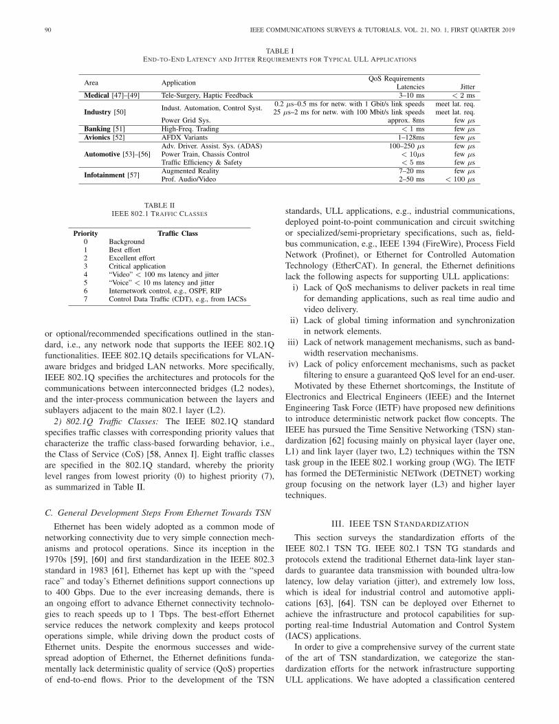
TABLE IEND-TO-END LATENCY AND JITTER REQUIREMENTS FOR TYPICAL ULL APPLICATIONS
TABLE IIIEEE 802.1 TRAFFIC CLASSES
or optional/recommended specifications outlined in the stan-dard, i.e., any network node that supports the IEEE 802.1Qfunctionalities. IEEE 802.1Q details specifications for VLAN-aware bridges and bridged LAN networks. More specifically,IEEE 802.1Q specifies the architectures and protocols for thecommunications between interconnected bridges (L2 nodes),and the inter-process communication between the layers andsublayers adjacent to the main 802.1 layer (L2).
2) 802.1Q Traffic Classes: The IEEE 802.1Q standardspecifies traffic classes with corresponding priority values thatcharacterize the traffic class-based forwarding behavior, i.e.,the Class of Service (CoS) [58, Annex I]. Eight traffic classesare specified in the 802.1Q standard, whereby the prioritylevel ranges from lowest priority (0) to highest priority (7),as summarized in Table II.
C. General Development Steps From Ethernet Towards TSN
Ethernet has been widely adopted as a common mode ofnetworking connectivity due to very simple connection mech-anisms and protocol operations. Since its inception in the1970s [59], [60] and first standardization in the IEEE 802.3standard in 1983 [61], Ethernet has kept up with the “speedrace” and today’s Ethernet definitions support connections upto 400 Gbps. Due to the ever increasing demands, there isan ongoing effort to advance Ethernet connectivity technolo-gies to reach speeds up to 1 Tbps. The best-effort Ethernetservice reduces the network complexity and keeps protocoloperations simple, while driving down the product costs ofEthernet units. Despite the enormous successes and wide-spread adoption of Ethernet, the Ethernet definitions funda-mentally lack deterministic quality of service (QoS) propertiesof end-to-end flows. Prior to the development of the TSN
standards, ULL applications, e.g., industrial communications,deployed point-to-point communication and circuit switchingor specialized/semi-proprietary specifications, such as, field-bus communication, e.g., IEEE 1394 (FireWire), Process FieldNetwork (Profinet), or Ethernet for Controlled AutomationTechnology (EtherCAT). In general, the Ethernet definitionslack the following aspects for supporting ULL applications:
i) Lack of QoS mechanisms to deliver packets in real timefor demanding applications, such as real time audio andvideo delivery.
ii) Lack of global timing information and synchronizationin network elements.
iii) Lack of network management mechanisms, such as band-width reservation mechanisms.
iv) Lack of policy enforcement mechanisms, such as packetfiltering to ensure a guaranteed QoS level for an end-user.
Motivated by these Ethernet shortcomings, the Institute ofElectronics and Electrical Engineers (IEEE) and the InternetEngineering Task Force (IETF) have proposed new definitionsto introduce deterministic network packet flow concepts. TheIEEE has pursued the Time Sensitive Networking (TSN) stan-dardization [62] focusing mainly on physical layer (layer one,L1) and link layer (layer two, L2) techniques within the TSNtask group in the IEEE 802.1 working group (WG). The IETFhas formed the DETerministic NETwork (DETNET) workinggroup focusing on the network layer (L3) and higher layertechniques.
III. IEEE TSN STANDARDIZATION
This section surveys the standardization efforts of theIEEE 802.1 TSN TG. IEEE 802.1 TSN TG standards andprotocols extend the traditional Ethernet data-link layer stan-dards to guarantee data transmission with bounded ultra-lowlatency, low delay variation (jitter), and extremely low loss,which is ideal for industrial control and automotive appli-cations [63], [64]. TSN can be deployed over Ethernet toachieve the infrastructure and protocol capabilities for sup-porting real-time Industrial Automation and Control System(IACS) applications.
In order to give a comprehensive survey of the current stateof the art of TSN standardization, we categorize the stan-dardization efforts for the network infrastructure supportingULL applications. We have adopted a classification centered
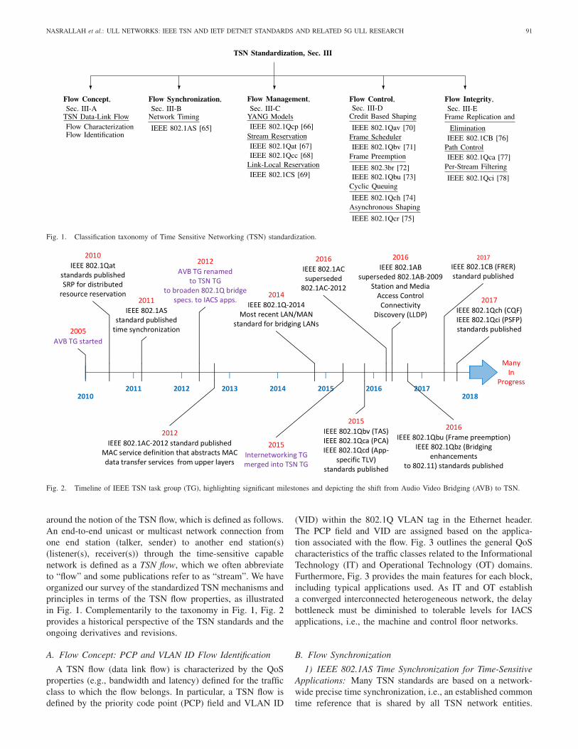
NASRALLAH et al.: ULL NETWORKS: IEEE TSN AND IETF DETNET STANDARDS AND RELATED 5G ULL RESEARCH 91
Fig. 1. Classification taxonomy of Time Sensitive Networking (TSN) standardization.
Fig. 2. Timeline of IEEE TSN task group (TG), highlighting significant milestones and depicting the shift from Audio Video Bridging (AVB) to TSN.
around the notion of the TSN flow, which is defined as follows.An end-to-end unicast or multicast network connection fromone end station (talker, sender) to another end station(s)(listener(s), receiver(s)) through the time-sensitive capablenetwork is defined as a TSN flow, which we often abbreviateto “flow” and some publications refer to as “stream”. We haveorganized our survey of the standardized TSN mechanisms andprinciples in terms of the TSN flow properties, as illustratedin Fig. 1. Complementarily to the taxonomy in Fig. 1, Fig. 2provides a historical perspective of the TSN standards and theongoing derivatives and revisions.
A. Flow Concept: PCP and VLAN ID Flow Identification
A TSN flow (data link flow) is characterized by the QoSproperties (e.g., bandwidth and latency) defined for the trafficclass to which the flow belongs. In particular, a TSN flow isdefined by the priority code point (PCP) field and VLAN ID
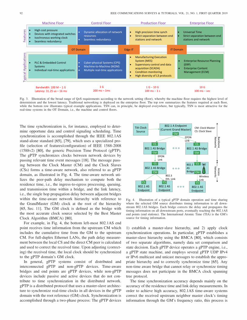
(VID) within the 802.1Q VLAN tag in the Ethernet header.The PCP field and VID are assigned based on the applica-tion associated with the flow. Fig. 3 outlines the general QoScharacteristics of the traffic classes related to the InformationalTechnology (IT) and Operational Technology (OT) domains.Furthermore, Fig. 3 provides the main features for each block,including typical applications used. As IT and OT establisha converged interconnected heterogeneous network, the delaybottleneck must be diminished to tolerable levels for IACSapplications, i.e., the machine and control floor networks.
B. Flow Synchronization
1) IEEE 802.1AS Time Synchronization for Time-SensitiveApplications: Many TSN standards are based on a network-wide precise time synchronization, i.e., an established commontime reference that is shared by all TSN network entities.
92 IEEE COMMUNICATIONS SURVEYS & TUTORIALS, VOL. 21, NO. 1, FIRST QUARTER 2019
Fig. 3. Illustration of the broad range of QoS requirements according to the network setting (floor), whereby the machine floor requires the highest level ofdeterminism and the lowest latency. Traditional networking is deployed on the enterprise floor. The top row summarizes the features required at each floor,while the bottom row illustrates typical example applications. TSN can, in principle, be deployed everywhere, but typically, TSN is most attractive for thereal-time systems in the OT Domain, i.e., the machine and control floors.
The time synchronization is, for instance, employed to deter-mine opportune data and control signaling scheduling. Timesynchronization is accomplished through the IEEE 802.1ASstand-alone standard [65], [79], which uses a specialized pro-file (selection of features/configuration) of IEEE 1588-2008(1588v2) [80], the generic Precision Time Protocol (gPTP).The gPTP synchronizes clocks between network devices bypassing relevant time event messages [18]. The message pass-ing between the Clock Master (CM) and the Clock Slaves(CSs) forms a time-aware network, also referred to as gPTPdomain, as illustrated in Fig. 4. The time-aware network uti-lizes the peer-path delay mechanism to compute both theresidence time, i.e., the ingress-to-egress processing, queuing,and transmission time within a bridge, and the link latency,i.e., the single hop propagation delay between adjacent bridgeswithin the time-aware network hierarchy with reference tothe GrandMaster (GM) clock at the root of the hierarchy[65, Sec. 11]. The GM clock is defined as the bridge withthe most accurate clock source selected by the Best MasterClock Algorithm (BMCA) [80].
For example, in Fig. 4, the bottom left-most 802.1AS endpoint receives time information from the upstream CM whichincludes the cumulative time from the GM to the upstreamCM. For full-duplex Ethernet LANs, the path delay measure-ment between the local CS and the direct CM peer is calculatedand used to correct the received time. Upon adjusting (correct-ing) the received time, the local clock should be synchronizedto the gPTP domain’s GM clock.
In general, gPTP systems consist of distributed andinterconnected gPTP and non-gPTP devices. Time-awarebridges and end points are gPTP devices, while non-gPTPdevices include passive and active devices that do not con-tribute to time synchronization in the distributed network.gPTP is a distributed protocol that uses a master-slave architec-ture to synchronize real-time clocks in all devices in the gPTPdomain with the root reference (GM) clock. Synchronization isaccomplished through a two-phase process: The gPTP devices
Fig. 4. Illustration of a typical gPTP domain operation and time sharingwhere the selected GM source distributes timing information to all down-stream 802.1AS bridges. Each bridge corrects the delay and propagates thetiming information on all downstream ports, eventually reaching the 802.1ASend points (end stations). The International Atomic Time (TIA) is the GM’ssource for timing information.
1) establish a master-slave hierarchy, and 2) apply clocksynchronization operations. In particular, gPTP establishes amaster-slave hierarchy using the BMCA [80], which consistsof two separate algorithms, namely data set comparison andstate decision. Each gPTP device operates a gPTP engine, i.e.,a gPTP state machine, and employs several gPTP UDP IPv4or IPv6 multicast and unicast messages to establish the appro-priate hierarchy and to correctly synchronize time [65]. Anynon-time aware bridge that cannot relay or synchronize timingmessages does not participate in the BMCA clock spanningtree protocol.
The time synchronization accuracy depends mainly on theaccuracy of the residence time and link delay measurements. Inorder to achieve high accuracy, 802.1AS time-aware systemscorrect the received upstream neighbor master clock’s timinginformation through the GM’s frequency ratio, this process is

NASRALLAH et al.: ULL NETWORKS: IEEE TSN AND IETF DETNET STANDARDS AND RELATED 5G ULL RESEARCH 93
called logical syntonization in the standard. In the synchroniza-tion context, frequency refers to the clock oscillator frequency.The frequency ratio is the ratio of the local clock frequencyto the frequency of the time-aware system at the other endof an attached link. 802.1AS achieves proper synchroniza-tion between time-aware bridges and end systems using boththe frequency ratio of the GM relative to the local clockto compute the synchronized time, and the frequency ratioof the neighbor CM relative to the local CS to correct anypropagation time measurements.
IEEE802.1AS-REV introduces new features needed fortime-sensitive applications. These features include the abilityto support multiple time domains to allow rapid switchovershould a GM clock fail, and improved time measurementaccuracy.
2) Summary and Lessons Learned: IEEE 802.1AS pro-vides reliable accurate network wide time synchronization.All gPTP systems compute both the residence time andthe link latency (propagation delay) and exchange messagesalong a hierarchical structure centered around the selectedGM clock to accurately synchronize time. Flow control andmanagement components, e.g., IEEE 802.1Qbv and 802.1Qcc(see Sections III-D and III-C), can utilize the 802.1AS tim-ing synchronization to provide accurate bounded latency andextremely low loss and delay variation for TSN applications.
An open aspect of time synchronization is that the frequentperiodic exchange of timing information between the individ-ual network entities can stress and induce backpressure on thecontrol plane. The control plane load due to the time synchro-nization can ultimately impact ULL applications. A centralizedtime synchronization system, e.g., based on a design similar tosoftware defined networking (SDN) [81], [82], with messageexchanges only between a central synchronization controllerand individual network entities could help mitigate the controlplane overhead. However, such a centralized synchronizationapproach may create a single-point of failure in the time syn-chronization process. The detailed quantitative study of thesetradeoffs is an interesting direction for future research.
C. Flow Management
Flow management enables users or operators to dynamicallydiscover, configure, monitor, and report bridge and end stationcapabilities.
1) IEEE 802.1Qcp YANG Data Model: The TSN TGhas proposed the IEEE 802.1Qcp TSN Configuration YANGmodel standard to achieve a truly universal Plug-and-Play (uPnP) model. The IEEE 802.1Qcp standard utilizesthe Unified Modeling Language (UML), specifically theYANG [83], [84] data model. The YANG data model pro-vides a framework for periodic status reporting as well asfor configuring 802.1 bridges and bridge components, includ-ing Media Access Control (MAC) Bridges, Two-Port MACRelays (TPMRs), Customer Virtual Local Area Network(VLAN) Bridges, and Provider Bridges [66]. Additionally,IEEE 802.1Qcp is used to support other TSN standard spec-ifications, such as the Security and Datacenter Bridging TGstandards 802.1AX and 802.1X.
YANG [83], [84] is a data modeling language for config-uration data, state data, remote procedure calls, and notifi-cations for network management protocols, e.g., NETCONFand RESTCONF. NETCONF is the Network ConfigurationProtocol [85] that provides mechanisms to install, manage,and delete the configurations of network devices. The indus-try wide adoption of the YANG formalized data modelinglanguage, e.g., by the IETF and the Metro Ethernet Forum(MEF), is an important motivation for integrating, automat-ing, and providing support for YANG data modeling in 802.1bridges and related services for upper layer components.
2) IEEE 802.1Qat Stream Reservation Protocol (SRP) andIEEE 802.1Qcc Enhancements to SRP and CentralizationManagement: The IEEE 802.1Qat Stream ReservationProtocol (SRP) [67], which has been merged into 802.1Q,provides a fundamental part of TSN. In particular, IEEE802.1Qat specifies the admission control framework for admit-ting or rejecting flows based on flow resource requirementsand the available network resources. Moreover, IEEE 802.1Qatspecifies the framework for reserving network resources andadvertising streams in packet switched networks over full-duplex Ethernet links. Most of the standards that use priorities,frame scheduling, and traffic shaping protocols depend onSRP [67], since these protocols work correctly only if thenetwork resources are available along the entire path fromthe sender (talker) to the receivers (listeners). IEEE 802.1Qatis a distributed protocol that was introduced by the AVBTG to ensure that the AVB talker is guaranteed adequatenetwork resources along its transmission path to the lis-tener(s). This is accomplished using the Multiple RegistrationProtocol (MRP) [58, Sec. 10], where the traffic streams areidentified and registered using a 48-bit Extended UniqueIdentifier (EUI-48). The EUI-48 is usually the MAC sourceaddress concatenated with a 16-bit handle to differentiate dif-ferent streams from the same source and is also referredto as StreamID. The SRP reserves resources for a streambased on the bandwidth requirement and the latency trafficclass using three signaling protocols, namely 1) the MultipleMAC Registration Protocol (MMRP), 2) the Multiple VLANRegistration Protocol (MVRP), and 3) the Multiple StreamRegistration Protocol (MSRP) [58], [67, Sec. 35].
MMRP and MVRP control the group registration propa-gation and the VLAN membership (MAC address informa-tion [58, Secs. 10 and 11]), while MSRP conducts the dis-tributed network resource reservation across bridges and endstations. MSRP registers and advertises data stream character-istics and reserves bridge resources to provide the appropriateQoS guarantees according to the talker’s declared propagationattributes, which include the SRP parameters that are sent bythe end station in MSRP PDUs (MSRPDUs). A station (talker)sends a reservation request with the MRP, i.e., the generalMRP application which registers the stream resource reserva-tion. The 802.1 TSN TG has developed the MRP AttributeDeclaration (MAD) for describing the request based on thestream characteristics. All participants in the stream have anMSRP application and MAD specification and each bridgewithin the same SRP domain can map, allocate, and for-ward the stream with the necessary resources using the MRP

94 IEEE COMMUNICATIONS SURVEYS & TUTORIALS, VOL. 21, NO. 1, FIRST QUARTER 2019
Fig. 5. Illustration of Multiple Registration Protocol (MRP) architecture:Each end station (illustrated on the right) declares the propagation attributesusing the MRP Attribute Declaration (MAD) and the MRP Applicationsencapsulated as an MRP participant which gives end stations the ability toregister resources. The MRP participant entry is stored in bridges and mappedbetween all required ports using MRP Attribute Propagation (MAP). A bridgemapping between two different interfaces in the LAN is illustrated on the left.
attribute propagation (MAP) [67]. Fig. 5 illustrates the MRParchitecture.
In essence, the SRP protocol ensures QoS constraints foreach stream through the following steps:
1) Advertise stream2) Register paths of stream3) Calculate worst-case latency4) Establish an AVB domain5) Reserve the bandwidth for the stream.
Since the existing IEEE 802.1Qat (802.1Q Section 35) SRPfeatures a decentralized registration and reservation pro-cedure, any changes or new requests for registrations orde-registrations can overwhelm the network and result in intol-erable delays for critical traffic classes. Therefore, the TSNTG has introduced the IEEE 802.1Qcc standard to improvethe existing SRP by reducing the size and frequency of reser-vation messages, i.e., relaxing timers so that updates are onlytriggered by link state or reservation changes.
Additionally, IEEE 802.1Qcc [68] provides a set of toolsto manage and control the network globally. In partic-ular, IEEE 802.1Qcc enhances the existing SRP with aUser Network Interface (UNI) which is supplemented by aCentralized Network Configuration (CNC) node, as shownin Fig. 6. The UNI provides a common method of request-ing layer 2 services. Furthermore, the CNC interacts with theUNI to provide a centralized means for performing resourcereservation, scheduling, and other types of configuration viaa remote management protocol, such as NETCONF [85] orRESTCONF [86]; hence, 802.1Qcc is compatible with theIETF YANG/NETCONF data modeling language.
For a fully centralized network, an optional Centralized UserConfiguration (CUC) node communicates with the CNC viaa standard Application Programming Interface (API), and canbe used to discover end stations, retrieve end station capa-bilities and user requirements, and configure delay-optimizedTSN features in end stations (mainly for closed-loop IACSapplications). The interactions with higher level reservationprotocols, e.g., RSVP, are seamless, similar to how the AVB
Fig. 6. Illustration of Centralized Network Configuration (CNC): Endstations interact with the network entities via the User-Network Interface(UNI). The CNC receives the requests, e.g., flow reservation requests, andprovides corresponding management functions. An optional CUC providesdelay-optimized configuration, e.g., for closed-loop IACS applications. Thesolid arrows represent the protocol, e.g., YANG or TLV, that is used asthe UNI for exchanging configuration information between Talkers/Listeners(users) and Bridges (network). The dashed arrows represent the protocol, e.g.,YANG or TLV, that transfers configuration information between edge bridgesand the CNC.
Transport Protocol IEEE 1722.1 [87] leverages the existingSRP.
802.1Qcc [68] still supports the fully distributed config-uration model of the original SRP protocol, i.e., allowsfor centrally managed systems to coexist with decentralizedad-hoc systems. In addition, 802.1Qcc supports a “hybrid”configuration model, allowing a migration path for legacy AVBdevices. This hybrid configuration management scheme whencoupled with IEEE 802.1Qca Path Control and Reservation(PCR) (see Section III-E2) and the TSN shapers can providedeterministic end-to-end delay and zero congestion loss.
3) IEEE 802.1CS Link-Local Reservation Protocol (LRP):To effectively achieve tight bounds on latency and zero con-gestion loss, traffic streams need to utilize effective admissioncontrol policies and secure resource registration mechanisms,such as the SRP [67] and the SRP enhancements and man-agement standard [68]. While the MRP [58, Sec. 10] providesefficient methods for registering streams; the database holdingthe stream state information, is limited to about 1500 bytes.As more traffic streams coexist and the network scaleincreases, MRP slows significantly as the database propor-tionally increases which results in frequent cyclic exchangesthrough the MAD between all bridge neighbors.
The Link-Local Reservation Protocol (LRP) [69] has beenintroduced by the 802.1 TSN TG to efficiently replicate anMRP database between two ends of a point-to-point link and toincrementally replicate changes as bridges report new networkdevelopments or conditions. Additionally, the LRP providesa purging process that deletes replicated databases when thesource of such databases remains unresponsive or the data getsstale. Furthermore, the LRP is optimized to efficiently handledatabases on the order of 1 Mbyte.
While MRP is considered application specific, i.e., the MRPoperations are defined by each registered application, LRPis an application neutral transport protocol. Fig. 7 illustrates

NASRALLAH et al.: ULL NETWORKS: IEEE TSN AND IETF DETNET STANDARDS AND RELATED 5G ULL RESEARCH 95
Fig. 7. Illustration of LRP Architecture: A Link-Local Reservation Protocol(LRP) instance (illustrated by the blue LRP box) interacts with each appli-cation and provides a generic transport service for multiple registered LRPapplications, which are represented by yellow colored boxes near the top ofthe illustration.
the LRP protocol architecture operating within bridges or endpoints.
4) Resource Allocation Protocol (RAP)—Towards aDistributed TSN Control Model: Although the SRP and therelated MSRP (MSRPv1 [68]) were designed for distributedstream configuration (including registration, reservation, andprovisioning), SRP is generally restricted to A/V applicationswith a limited number of Stream Reservation (SR) classes,e.g., classes A and B for the Credit Based Shaper (CBS),see Section III-D1. SRP guarantees the QoS characterizedby each stream through the reservation in conjunction withshaper mechanisms, see Section III-D. IEEE 802.1Qcc pushedfor more centralized configuration models, where all thenewly established TSN features, e.g., shaping, preemption,and redundancy, are supported through the CNC configurationmodel. Any distributed model is currently restricted to CBS.
The Resource Allocation Protocol (RAP) [88] leveragesthe LRP to propagate TSN stream configuration frames thatinclude resource reservation and registration information ina manner similar to MSRP. The MSRP (and MSRPv1) isgeared towards AVB systems, while RAP is defined for TSNenabled systems for distributed stream configuration. The RAPpromises to improve scalability (through LRP), to support allTSN features, to improve performance under high utilization,and to enhance diagnostic capabilities.
5) Summary and Lessons Learned: Flow managementallows distributed (legacy SRP and RAP) as well as central-ized (802.1Qcc and 802.1CS) provisioning and management ofnetwork resources, effectively creating protected channels overshared heterogeneous networks. Moreover, flow managementoffers users and administrators Operations, Administration,Maintenance (OAM) functions to monitor, report, and con-figure (802.1Qcp and 802.1Qcc) network conditions. Thisallows for fine-grained support of network services whileenforcing long term allocations of network resources withflexible resource control through adaptive and automaticreconfigurations.
However, both centralized and distributed flow man-agement models have specific deployment advantages and
disadvantages. For example, a centralized entity presents a sin-gle point of failure, whereas, distributed schemes incur exten-sive control plane overheads. A centralized scheme can benefitfrom SDN implementation and management but could resultin new infrastructure cost for the operators. Nevertheless,the choice of deployments can be based on the relativeperformance levels among centralized and distributed nodes, aswell as the use of existing infrastructures and the deploymentof new infrastructures. Future research needs to thoroughlyexamine these tradeoffs.
Another important future research direction is to exam-ine predictive models that estimate the resource reservationrequirements in bridges. Estimations may help in effectivelymanaging queues and scheduling while efficiently utilizing thenetwork resources.
D. Flow Control
Flow control specifies how frames belonging to a prescribedtraffic class are handled within TSN enabled bridges.
1) IEEE 802.1Qav Forwarding and Queuing of Time-Sensitive Streams: IEEE 802.1Qav specifies Forwarding andQueuing of Time Sensitive Streams (FQTSS), which hasbeen incorporated into 802.1Q. IEEE 802.1Qav serves as amajor enhancement to the forwarding and queuing opera-tion in traditional Ethernet networks. IEEE 802.1Qav spec-ifies bridge operations that provide guarantees for time-sensitive (i.e., bounded latency and jitter), lossless real-timeaudio/video (A/V) traffic [70]. The IEEE 802.1Qav stan-dard [58], [70, Sec. 34], details flow control operations, suchas per priority ingress metering and timing-aware queuedraining algorithms.
IEEE 802.1Qav was developed to limit the amount of A/Vtraffic buffering at the downstream receiving bridges and/orend stations. Increasing proportions of bursty multimedia traf-fic can lead to extensive buffering of multimedia traffic, poten-tially resulting in buffer overflows and packet drops. Packetdrops may trigger retransmissions, which increase delays, ren-dering the re-transmitted packets obsolete and diminishing theQuality of Experience (QoE).
IEEE 802.1Qav limits the amount of buffering required inthe receiving station through the Stream Reservation Protocol(SRP) [67] in conjunction with a credit-based shaper (CBS).The CBS spaces out the A/V frames to reduce bursting andbunching. This spacing out of A/V frames protects best-efforttraffic as the maximum AVB stream burst is limited. The spac-ing out of A/V frames also protects the AVB traffic by limitingthe back-to-back AVB stream bursts, which can interfere andcause congestion in the downstream bridge.
The CBS shaper separates a queue into two traffic classes,class A (tight delay bound) and class B (loose delay bound).Each class queue operates according to the throttling mech-anism illustrated in Fig. 8. When no frame is available inthe queue, the credit for the queue is set to zero. A queueis eligible for transmission if the credit is non-negative. Thecredit is increased by idleSlope when there is at least oneframe in the queue, and decreased by sendSlope when aframe is transmitted. The idleSlope is the actual bandwidth
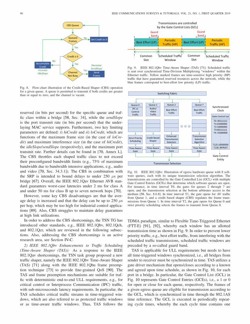
96 IEEE COMMUNICATIONS SURVEYS & TUTORIALS, VOL. 21, NO. 1, FIRST QUARTER 2019
Fig. 8. Flow-chart illustration of the Credit-Based Shaper (CBS) operationfor a given queue. A queue is permitted to transmit if both credits are greaterthan or equal to zero, and the channel is vacant.
reserved (in bits per second) for the specific queue and traf-fic class within a bridge [58, Sec. 34], while the sendSlopeis the port transmit rate (in bits per second) that the under-laying MAC service supports. Furthermore, two key limitingparameters are defined: i) hiCredit and ii) loCredit, which arefunctions of the maximum frame size (in the case of loCre-dit) and maximum interference size (in the case of hiCredit),the idleSlope/sendSlope (respectively), and the maximum porttransmit rate. Further details can be found in [70, Annex L].The CBS throttles each shaped traffic class to not exceedtheir preconfigured bandwidth limits (e.g., 75% of maximumbandwidth due to bandwidth intensive applications, e.g., audioand video [70, Sec. 34.3.1]). The CBS in combination withthe SRP is intended to bound delays to under 250 µs perbridge [67]. Overall, the IEEE 802.1Qav Ethernet AVB stan-dard guarantees worst-case latencies under 2 ms for class Aand under 50 ms for class B up to seven network hops [70].
However, some key CBS disadvantages are that the aver-age delay is increased and that the delay can be up to 250 µsper hop, which may be too high for industrial control applica-tions [89]. Also, CBS struggles to maintain delay guaranteesat high link utilizations.
In order to address the CBS shortcomings, the TSN TG hasintroduced other standards, e.g., IEEE 802.1Qbv, 802.1Qch,and 802.1Qcr, which are reviewed in the following subsec-tions. Also, addressing the CBS shortcomings is an activeresearch area, see Section IV-C.
2) IEEE 802.1Qbv Enhancements to Traffic Scheduling(Time-Aware Shaper (TAS)): As a response to the IEEE802.1Qav shortcomings, the TSN task group proposed a newtraffic shaper, namely the IEEE 802.1Qbv Time-Aware Shaper(TAS) [71] along with the IEEE 802.1Qbu frame preemp-tion technique [73] to provide fine-grained QoS [90]. TheTAS and frame preemption mechanisms are suitable for traf-fic with deterministic end-to-end ULL requirements, e.g., forcritical control or Interprocess Communication (IPC) traffic,with sub-microseconds latency requirements. In particular, theTAS schedules critical traffic streams in time-triggered win-dows, which are also referred to as protected traffic windowsor as time-aware traffic windows. Thus, TAS follows the
Fig. 9. IEEE 802.1Qbv Time-Aware Shaper (TAS) [71]: Scheduled trafficis sent over synchronized Time-Division Multiplexing “windows” within theEthernet traffic. Yellow marked frames are time-sensitive high priority (HP)traffic that have guaranteed reserved resources across the network, while theblue frames correspond to best-effort low priority (LP) traffic.
Fig. 10. IEEE 802.1Qbv: Illustration of egress hardware queue with 8 soft-ware queues, each with its unique transmission selection algorithm. Thetransmissions are controlled by the Gate Controlled List (GCL) with multipleGate Control Entries (GCEs) that determine which software queues are open.For instance, in time interval T0, the gates for queues 2 through 7 areopen, and the transmission selection at the bottom arbitrates access to themedium [58, Sec. 8.6.8]. In time interval T1, the gate opens for AV trafficfrom Queue 1, and a credit based shaper (CBS) regulates the frame trans-missions from Queue 1. In time interval T2, the gate opens for Queue 0 andstrict priority scheduling selects the frames to transmit from Queue 0.
TDMA paradigm, similar to Flexible Time-Triggered Ethernet(FTT-E) [91], [92], whereby each window has an allottedtransmission time as shown in Fig. 9. In order to prevent lowerpriority traffic, e.g., best effort traffic, from interfering with thescheduled traffic transmissions, scheduled traffic windows arepreceded by a so-called guard band.
TAS is applicable for ULL requirements but needs to haveall time-triggered windows synchronized, i.e., all bridges fromsender to receiver must be synchronized in time. TAS utilizes agate driver mechanism that opens/closes according to a knownand agreed upon time schedule, as shown in Fig. 10, for eachport in a bridge. In particular, the Gate Control List (GCL) inFig. 10 represents Gate Control Entries (GCEs), i.e., a 1 or 0for open or close for each queue, respectively. The frames ofa given egress queue are eligible for transmission according tothe GCL, which is synchronized in time through the 802.1AStime reference. The GCL is executed in periodically repeat-ing cycle times, whereby the each cycle time contains one

NASRALLAH et al.: ULL NETWORKS: IEEE TSN AND IETF DETNET STANDARDS AND RELATED 5G ULL RESEARCH 97
Fig. 11. The IEEE 802.1Qbv transmission selection prevents low priority(best effort) frames from starting transmission if the transmission cannot becompleted by the start of the scheduled traffic window. This transmissionselection essentially enforces a guard band (sized as a maximum size frame)to protect the scheduled traffic window. With preemption (IEEE 802.3br, IEEE802.1Qbu) the guard band can be reduced to the smallest Ethernet framefragment.
GCL execution. Within a cycle time, the time period duringwhich a gate is open is referred to as the time-aware traf-fic window. Frames are transmitted according to the GCL andtransmission selection decisions, as illustrated in Fig. 10. Eachindividual software queue has its own transmission selectionalgorithm, e.g., strict priority queuing (which is the default).Overall, the IEEE 802.1Qbv transmission selection at the bot-tom of Fig. 10 transmits a frame from a given queue withan open gate if: (i) The queue contains a frame ready fortransmission, (ii) higher priority traffic class queues with anopen gate do not have a frame to transmit, and (iii) the frametransmission can be completed before the gate closes for thegiven queue. Note that these transmission selection conditionsensure that low priority traffic is allowed to start transmissiononly if the transmission will be completed by the start of thescheduled traffic window for high priority traffic. Thus, thistransmission selection effectively enforces a “guard band” toprevent low priority traffic from interfering with high prioritytraffic, as illustrated in Fig. 11.
One critical TAS shortcoming is that some delay is incurreddue to additional sampling delay, i.e., due the waiting timeuntil the next time-triggered window commences. This sam-pling delay arises when unsynchronized data is passed froman end-point to the network. Task and message schedulingin end-nodes would need to be coupled with the TAS gatescheduling in the networks in order to achieve the lowestlatencies. Moreover, synchronizing TSN bridges, frame selec-tions, and transmission times across the network is nontrivialin moderately sized networks, and requires a fully managednetwork. Also, the efficient use of bandwidth with TAS needsto be thoroughly examined. Overall, TAS has high configura-tion complexity. Future research needs to carefully examinethe scalability to large networks, runtime reconfiguration, andthe integration of independently developed sub-systems.
3) IEEE 802.3br and 802.1Qbu Interspersing ExpressTraffic (IET) and Frame Preemption: To address the ULLlatency requirements and the inverted priority problem, i.e.,the problem that an ongoing transmission of a low priorityframe prevents the transmission of high priority frames, the802.1 TG along with the 802.3 TG introduced frame preemp-tion (802.1Qbu and 802.3br) [72], [73]. Frame preemption
Fig. 12. Illustration of the layering for the Ethernet MAC Merge Sublayer:The MAC Merge Sublayer provides a Reconciliation Sublayer (RS) servicefor pMAC and eMAC frames. The RS service supports two main ways tohold the transmission of a pMAC frame in the presence of an eMAC frame:By preempting (interrupting) the pMAC frame transmission, or by preventingthe start of the pMAC frame transmission.
separates a given bridge egress port into two MAC serviceinterfaces, namely preemptable MAC (pMAC) and expressMAC (eMAC), as illustrated in Fig. 12. A frame preemptionstatus table maps frames to either pMAC or eMAC; by defaultall frames are mapped to eMAC. Preemptable frames that arein transit, i.e., they are holding on to the resource (transmissionmedium), can be preempted by express frames. After the trans-mission of an express frame has completed, the transmissionof the preempted frame can resume.
With preemption, the guard band in Fig. 9 can be reducedto the transmission time of the shortest low priority framefragment. Thus, in the worst case, the transmission of the lowpriority frame fragment can be completed before starting thetransmission of the next high priority frame. The transmis-sion of the leftover fragmented frame can then be resumedto completion. Note that this preemption occurs only at thelink-level, and any fragmented frame is reassembled at theMAC interfaces. Hence the switches process internally onlycomplete frames. That is, any frame fragments transmittedover a physical link to the next bridge are re-assembled inthe link layer interface; specifically, the MAC merge sublayer(see Fig. 12) in the link layer of the next bridge, and thenext bridge then only processes complete frames. Each pre-emption operation causes some computational overhead dueto the encapsulation processing by the bridge to suspend thecurrent fragment and to transition the operational context tothe express traffic frame and vice versa, which is illustratedin Fig. 11. Note that this overhead occurs only in layer 2 inthe link interface.
4) IEEE 802.1Qch Cyclic Queuing and Forwarding (CQF):While the IEEE 802.1Qav FQTSS with CBS works wellfor soft real-time constraints, e.g., A/V traffic, the existingFQTSS has still several shortcomings, including, i) pathologi-cal topologies can result in increased delay, and ii) worst-casedelays are topology dependent, and not only hop countdependent, thus buffer requirements in switches are topol-ogy dependent. The TSN TG introduced Cyclic Queuing andForwarding (CQF) [74], also known as the Peristaltic Shaper(PS), as a method to synchronize enqueue and dequeue oper-ations. The synchronized operations effectively allow LANbridges to synchronize their frame transmissions in a cyclic

98 IEEE COMMUNICATIONS SURVEYS & TUTORIALS, VOL. 21, NO. 1, FIRST QUARTER 2019
Fig. 13. Illustration of Cyclic Queuing and Forwarding (CQF) without pre-emption for a linear network: Each High Priority (HP) traffic frame scheduledon a cycle (even or odd) is scheduled to be received at the next bridge in thenext cycle, whereby the worst-case HP frame delay can be two cycle times. Inthe illustrated example, the HP traffic is delayed due to low priority interferingtraffic, but still meets the two cycle time delay bound.
Fig. 14. Illustration of CQF with preemption for a linear network: A GuardBand (GB) before the start of the cycle prevents any interfering (LP) trafficfrom affecting the High Priority (HP) traffic. The CQF without preemption inFig. 13 did not prevent the LP traffic from interfering with HP traffic, whilethe CQF with preemption prevented the LP traffic from interfering with HPtraffic. Thus, preemption can improve the performance for HP traffic.
manner, achieving zero congestion loss and bounded latency,independently of the network topology.
Suppose that all bridges have synchronized time, i.e., allbridges are 802.1AS enabled bridges, and suppose for sim-plicity of the discussions that wire lengths and propagationtimes are negligible. Then, time sensitive streams are sched-uled (enqueued and dequeued) at each time interval or cycletime with a worst-case deterministic delay of two times thecycle time between the sender (talker) and the downstreamintermediate receiver, as illustrated in Fig. 13. In essence, thenetwork transit latency of a frame is completely characterizedby the cycle time and the number of hops. Therefore, the framelatency is completely independent of the topology parametersand other non-TSN traffic.
CQF can be combined with frame preemption specified inIEEE 802.3Qbu, to reduce the cycle time from the transmis-sion time of a full size frame to the transmission time of aminimum size frame fragment (plus all the TSN traffic), asillustrated in Fig. 14. Note however that for CQF to work cor-rectly, all frames must be kept to their allotted cycles, i.e.,all transmitted frames must be received during the expectedcycle at the receiving downstream intermediate bridge [74].Therefore, the cycle times, the alignment of the cycle timesamong the bridges in the network, and the timing of the firstand last transmissions within a cycle need to be carefully con-sidered in order to ensure that the desired latency bounds areachieved. To this end, CQF in conjunction with IEEE 802.1Qciingress policing and the IEEE 802.1Qbv TAS ensures that allframes are kept within a deterministic delay and guaranteedto be transmitted within their allotted cycle time.
5) IEEE 802.1Qcr Asynchronous Traffic Shaping (ATS):While CQF and TAS provide ULL for critical traffic,they depend on network-wide coordinated time and, impor-tantly, due to the enforced packet transmission at forcedperiodic cycles, they utilize network bandwidth ineffi-ciently [89]. To overcome these shortcomings, the TSN TGhas proposed the IEEE 802.1Qcr Asynchronous Traffic Shaper(ATS) [75], which is based on the urgency-based sched-uler (UBS) [89], [93]. The ATS aims to smoothen trafficpatterns by reshaping TSN streams per hop, implementingper-flow queues, and prioritizing urgent traffic over relaxedtraffic. The ATS operates asynchronously, i.e., bridges and endpoints need not be synchronized in time. Thus, ATS can uti-lize the bandwidth efficiently even when operating under highlink utilization with mixed traffic loads, i.e., both periodic andsporadic traffic.
The UBS is based on the Rate-Controlled ServiceDisciplines (RCSDs) [94]. RCSDs are a non-work conserv-ing class of packet service disciplines which includes Rate-Controlled Static Priority [95] and Rate-Controlled EarliestDeadline First [96]. The RCSD packet scheduling consistof two components: the rate controller implements the rate-control policies, and the scheduler implements the packetscheduling according to some scheduling policy, e.g., Static-Priority, First-Come-First-Serve, or Earliest Due-Date First.By separating the rate controller and scheduler, the RCSDeffectively decouples the bandwidth for each stream from itsdelay bound, i.e., allocating a prescribed amount of bandwidthto an individual stream is independent of the delay bound.Hence, RCSD can support low delay and low bandwidthstreams.
UBS adds a few improvements to RCSDs [94], namely:1) UBS provides low and predictable worst-case delays evenat high link utilization, 2) low implementation complexity dueto the separation of per-flow queues from per-flow states whereflow state information, such as Head-of-Queue frame and timestamp, is stored, and 3) independence from the global refer-ence time synchronization; specifically, individual flow delaysare analyzed at each hop, i.e., per-hop delay calculation, andend-to-end delays are calculated based on the network topol-ogy and by the closed-form composition of the per-hop delayscalculated initially.
The fundamental aim of the RCSD is to individually con-trol frame selection and transmission at each hop between thetransmitter and receiver, i.e., per hop shaping. As pointed outby Specht and Samii [89], the RCSD has multiple scalabil-ity problems, including dynamic reordering of packets withinseparate queues according to the packets’ eligibility times, i.e.,priority queue implementation with non-constant complex datastructures, such as heaps. Specialized calender queues havebeen proposed to achieve constant complexity [89]. However,calender queues require RCSD capable switches to have largememory pools, are difficult to control as the network sizescales up, and are ideal only for some specific applicationswith special properties. Therefore, Specht and Samii [89] uti-lize the RCSD concept with the outlined improvements andhave proposed a novel UBS solution as the core of the ATSstandard.

NASRALLAH et al.: ULL NETWORKS: IEEE TSN AND IETF DETNET STANDARDS AND RELATED 5G ULL RESEARCH 99
6) Summary and Lessons Learned: Flow control mainlyenforces rules to efficiently forward and appropriately queueframes according to their associated traffic classes. All existingflow controls follow similar principles, namely, certain privi-leges are associated with TSN flows while non-TSN flows aredelayed. Nearly all existing schedulers and shapers enforcefair transmission opportunities according to each flow’s trafficclass. The transmission selection algorithm selects the appro-priate stream within a given traffic class according to thenetwork and traffic conditions. Flow control collaborates withflow management, see Section III-C, and flow integrity, seeSection III-E, to ensure adequate resources are available forTSN streams.
Overall, we can classify real-time TSN systems into event-triggered systems and time-triggered systems. For exam-ple, IEEE 802.1Qbv is a time-triggered shaper, while IEEE802.1Qcr is an event-triggered shaper. An interesting futureresearch direction is to explore whether both types of shaperscan be combined. That is, would it be efficient to dynami-cally change a flow’s priority, individually or collectively, andto reshape flows based on neighbor network conditions whileeach flow is shaped by a centralized computed schedule incor-porating time slots at each egress’s port? For example, a streaminitially sent with a certain high priority can be downgraded tolow priority based on downstream network conditions whileadhering to each bridge’s time-aware scheduler and gatingmechanism.
Also, it will be interesting to investigate whetherIEEE 802.1Qbv can be replaced with an event-triggered shaperthat guarantees an upper bound on latency, but not generallya deterministic latency. Changing TAS into an event-triggeredshaper can lead to more flexible and easily computed sched-ules since certain events, e.g., incoming frames or networkchanges, can require schedule changes at runtime.
E. Flow Integrity
To accomplish the goals of deterministic ultra-low latency,jitter, and packet loss, TSN streams need to deliver their framesregardless of the dynamic network conditions, including phys-ical breakage and link failures. Several techniques have beenstandardized to enable flow integrity.
1) IEEE 802.1CB Frame Replication and Elimination forReliability (FRER): IEEE 802.1CB Frame Replication andElimination for Reliability (FRER) [76], is a stand-alone stan-dard that ensures robust and reliable communication usingproactive measures for applications that are intolerant to packetlosses, such as control applications. 802.1CB FRER minimizesthe impact of congestion and faults, such as cable breakages,by sending duplicate copies of critical traffic across disjointnetwork paths, as shown in Fig. 15. If both frames reach theirdestination, the duplicate copy is eliminated. If one copy failsto reach its destination, the duplicate message can still bereceived, effectively providing seamless proactive redundancyat the cost of additional network resources.
In order to minimize network congestion, the packet repli-cation can be selected based on traffic class and the pathinformation acquired through the TSN stream identification
Fig. 15. Illustration of FRER operation: The first bridge replicates the frameand transmits the duplicated frames on two disjoint paths. The FRER operationcan be started and ended at any bridge between the sender and receiver.
(stream_handle), plus a sequence generation function. Thesequence generation function generates identification numbersfor replicated frames to determine which frames to discard andwhich frames to pass on so as to ensure correct frame recoveryand merging. The frame redundancy information is carried ina Redundancy Tag [76]. Frame sequence numbers and timinginformation are also required to limit the memory needed forduplicate frame detection and elimination. For example, FRERmay only be employed for critical traffic, while best effortand other loss-tolerant traffic is transmitted normally. FRERis compatible with industrial fault-tolerance architectures, e.g.,High Availability and Seamless Redundancy (HSR) [97] andthe Parallel Redundancy Protocol (PRP) [98]. We note thatframe duplication, routing, and elimination are non-trivialtasks that will likely require centralized management. Hence,such protocols can be combined with other standards, e.g.,802.1Qcc and 802.1Qca, to ensure seamless redundancy andfast recovery in time-sensitive networks.
2) IEEE 802.1Qca Path Control and Reservation (PCR):IEEE 802.1Qca Path Control and Reservation (PCR) isbased on and specifies TLV extensions to the IETF LinkState Protocol (LSP), the Intermediate Station to IntermediateStation (IS-IS) protocol [99]. IEEE 802.1Qca allows the IS-ISprotocol to control bridged networks beyond the capabilitiesof shortest path routing (ISIS-SPB) [58], [100, Sec. 28], con-figuring multiple paths through the network [77], [101]. IEEE802.1Qca PCR aims to integrate control protocols requiredto provide explicit forwarding path control, i.e., predefinedprotected path set-up in advance for each stream, band-width reservation, data flow redundancy (both protection andrestoration), and distribution of control parameters for flowsynchronization and flow control messages [77].
In general, 802.1Qca specifies bridging on explicit paths(EPs) for unicast and multicast frame transmission, and pro-tocols to determine multiple active topologies, e.g., ShortestPath, Equal Cost Tree (ECT), Internal Spanning Tree (IST),Multiple Spanning Tree Instance (MSTI), and Explicit Tree(ET), in a bridged network. Explicit forwarding paths,as opposed to hop-by-hop forwarding, mitigate disruptionscaused by the reconvergence of bridging protocols. PCR hassimilar goals and evolved from spanning tree protocols, e.g.,the Rapid Spanning Tree Protocol (RSTP) [58, Sec. 13.4], theMultiple Spanning Tree Protocol (MSTP) [58, Sec. 13.5], andthe Shortest Path Bridging (SPB) [58, Sec. 27].
The IEEE 802.1Qca standard is based on Shortest PathBridging (SPB) [58, Sec. 27] and incorporates a SoftwareDefined Networking (SDN) hybrid approach [77]. In the

100 IEEE COMMUNICATIONS SURVEYS & TUTORIALS, VOL. 21, NO. 1, FIRST QUARTER 2019
Fig. 16. Illustration of Explicit Paths (EPs): A control plane PCE SDNcontroller installs computed Explicit Tree (ET) paths via the IS-IS data plane.Two computed ET paths are shown represented by the green and blue lines.
hybrid approach, the IS-IS protocol in the data plane han-dles basic functions, e.g., topology discovery and default pathcomputation, while the SDN controller [102] in the controlplane manages the Explicit Paths (EPs), as shown in Fig. 16.In particular, the controller utilizes dedicated path computationserver nodes called Path Computation Elements (PCEs) [103],defined by the IETF PCE WG [103], to manage the EPs. APCE interacts with the IS-IS protocol to handle and installrequests for the network and can interact with the SRP pro-tocol, see Section III-C, to reserve resources along the EPs.Additionally, the PCEs can manage redundancy on the EPs,thus providing protection on top of the EPs by utilizing alter-nate paths, e.g., Loop Free Alternates (LFAs) [77], that reroutein a few milliseconds.
3) IEEE 802.1Qci Per-Stream Filtering and Policing(PSFP): The IEEE 802.1Qci per-stream filtering and policing(PSFP) standard [78], also known as ingress policing/gatingstandard, filters and polices individual traffic streams based onrule matching. IEEE 802.1Qci prevents traffic overload condi-tions, that are caused, for instance, by erroneous delivery dueto equipment malfunction and Denial of Service (DoS) attacks,from affecting intermediate bridge ports and the receiving endstation, i.e., improves network robustness. IEEE 802.1Qci maybe used to protect against software bugs on end points orbridges, but also against hostile devices and attacks. IEEE802.1Qci specifies filtering on a per flow (stream) basis byidentifying individual streams with a StreamID, which utilizesthe 802.1CB stream handler method [76]. The identified indi-vidual streams can then be aggregated, processed, and finallyqueued to an input gate. As illustrated in Fig. 17, each gateperforms three functions.
The PSFP stream filter performs per-flow filtering by match-ing frames with permitted stream IDs and priority levels, andthen applies policy actions. The PSFP stream gate coordinatesall streams such that all frames proceed in an orderly anddeterministic fashion, i.e., similar to the 802.1Qch signalingprocess, see Section III-D4. The PSFP flow metering enforcespredefined bandwidth profiles for streams. The metering may,for instance, enforce prescribed maximum information ratesand burst sizes.
4) Summary and Lessons Learned: Flow integrity providespath redundancy, multi-path selection, as well as queue filter-ing and policing. Flow integrity also prevents unauthorized ormismanaged and rogue streams on bridged LAN networks.
Fig. 17. Illustration of PSFP flow: The flow is first filtered accordingto per-flow policies. Then, a gating mechanism regulates the flow. Finally,flow metering ensures bandwidth limitations before a frame is queued forforwarding.
In general, as network devices improve in terms of hardwareperformance, they can be equipped with more state informa-tion within the core network. The increased state informationallows for fine granular QoS management at the expense ofcontrol messages for efficient control dissemination in thenetwork. Future research needs to carefully examine the trade-offs between disseminating more extensive control messagesand the resulting QoS management improvements.
F. Discussion on TSN Standardization
The IEEE TSN TG has standardized deterministicnetworking for Layer 2 Ethernet based bridging LANs. Thesestandards have been revised and continue to be updated toreflect the convergence of the industrial and consumer mar-kets. Overall, the TSN standards guarantee the required QoSrequirements for data transmission and provide sufficient mea-sures to enable end-to-end functional communication safety inthe network. Essentially, the TSN standardization provides therecommended practices for enabling low latency, jitter, anddata loss, as well as redundancy and reservation. In addition,the TSN standardization provides mechanisms for bandwidthlimitation, dynamic reconfiguration, centralized management,and strict timing features.
Timing measurement and sub-microsecond time synchro-nization as basis for TSN standard mechanisms can beachieved with IEEE 802.1AS and the updated revised version802.1AS-REV. Essentially, all gPTP network entities con-tribute to distributing and correcting delay measurement timinginformation based on the source GM. 802.1AS-REV provides,among others, GM redundancy for fast convergence.
Several flow management standards, including IEEE802.1CB (FRER), 802.1Qca (PCR), 802.1Qci (PSFP),802.1Qcc (Enhanced SRP and centralized Management), and802.1CS (LRP) and RAP have been published or are inprogress to enable redundancy, path reservation, bandwidthlimitation, dynamic reconfiguration, as well as overall flowintegrity and management. Although standard Ethernet pro-vides redundancy features, e.g., through spanning tree proto-cols, the convergence time in the event of a failure is tooslow for real-time IACS applications. Therefore, FRER isused to proactively enable seamless data redundancy at thecost of additional bandwidth consumption. Moreover, PCR in

NASRALLAH et al.: ULL NETWORKS: IEEE TSN AND IETF DETNET STANDARDS AND RELATED 5G ULL RESEARCH 101
combination with FRER and 802.1Qcc enables fast recovery,efficient path redundancy, and dynamic runtime flow man-agement. Furthermore, PSFP manages, controls, and preventsrogue flows from deteriorating the network performance. SRPand the related signaling protocols are fully distributed mech-anisms targeted towards AVB applications; however, the SRPand MRP protocols are not scalable to large networks withreal-time IACS applications due to a limited state informa-tion database for the registered flows, see Section III-C3.Therefore, LRP in conjunction with RAP as the signaling pro-tocol features a decentralized approach to support resourcereservations for scalable TSN enabled networks.
To achieve low latency, several flow control standards havebeen released, including IEEE 802.1Qbv (TAS), 802.1Qch(CQF), and IEEE 802.1Qcr (ATS). For TAS, IEEE 802.1Qbuframe preemption can ensure that the transmission chan-nel is free for the next express traffic transmission. CQFcan coordinate ingress and egress operations to reduce theTAS configuration complexity, albeit at the expense of higherdelays. Finally, ATS has been proposed to provide determin-istic operations independently of the reference time synchro-nization and low delays for high link utilization. The efficientdynamic configuration of these flow control standard mech-anisms, including IEEE 802.1Qbv, is an open challenge thatrequires extensive future standardization and research efforts.
The TSN mechanisms (and similarly the DetNet mecha-nisms) do not explicitly define mechanisms to specificallyreduce packet jitter. The various TSN mechanisms for ensur-ing very short deterministic packet delays implicitly achievevery low packet jitter. Moreover, resource reservation andadmission control can further reduce end-to-end jitter by lim-iting interfering traffic, which is typically the main cause ofjitter. Additionally, CQF can coordinate ingress and egressoperations, which can cause jitter, to reduce delays to sub-microsecond levels or to bound delays to within a fewmicroseconds, effectively eliminating jitter caused by the phys-ical properties of links and switching fabrics [104]. However,while it is very unlikely that high jitters occur in a TSNnetwork, in the event of high jitter, the TSN standards donot actively delay or throttle flows to compensate for the highjitter condition. Such specific jitter control operations are anopen issue for potential future TSN standards development.
The TSN standardization has so far excluded the spe-cific consideration of security and privacy. The IEEE 802.1Security TG has addressed security and privacy in gen-eral IEEE 802.1 networks, i.e., functionalities to supportsecure communication between network entities, i.e., endstations and bridges. The TG has detailed a number of stan-dards and amendments, including 802.1X Port-based NetworkAccess Control (PNAC) [105], [106], 802.1AE MAC Security(MACsec) [107]–[110], and 802.1AR Security Device Identity(DevID) [111], that focus on providing authentication, autho-rization, data integrity, and confidentiality. Specifically, PNACutilizes industry standard authentication and authorizationprotocols enabling robust network access control and theestablishment of a secure infrastructure. Furthermore, PNACspecifies the MACsec Key Agreement (MKA) [106] proto-col. MACsec specifies the use of cryptographic cipher suites,
e.g., Galois/Counter Mode of Advanced Encryption Standardcipher with 128-bit key (GCM-AES-128), that allow for con-nectionless user data confidentiality, frame data integrity, anddata origin authentication, essentially providing a set of proto-cols that ensures protection for data traversing Ethernet LANs.For instance, DevID is a unique per-device identifier that cryp-tographically binds a device to the DevID. Thus, 802.1 LANdevices can be authenticated and appropriate policies for trans-mission and reception of data and control protocols to andfrom devices can be applied. The IEEE 802.1 Security TGis working on a couple of amendments to address privacyconcerns and to include a YANG model allowing configu-ration and status reporting for PNAC in 802.1 LANs. Theintegration of the security protocols and standards with TSNenabled networks needs to be addressed in future research andstandardization. For instance, the impact of the security stackoverhead on TSN flows and the impact of the security over-head on OT related applications running over Ethernet LANsneed to be investigated. Thus, there are ample research oppor-tunities for testing and benchmarking to ensure the efficientintegration of legacy security protocols with TSN.
The important area of networks for industrial appli-cations often employs cut-through switching techniques.An interesting future research direction is to investigatehow networking with cut-through switching compares withnetworking based on the TSN standards (tool sets).
More broadly, even though many standards and recom-mended practices addressing deterministic networking havebeen published, significant testing and benchmarking is neededto provide assurances to the industry and consumer markets.
IV. TSN RESEARCH STUDIES
This section surveys the existing research studies towardsachieving ULL in the context of the TSN standards. The TSNstandards provide tool sets to enable TSN characteristics, suchas flow synchronization and flow control (see Section III),in conventional networks. Based on the application require-ments, various TSN standard tools can be independently andselectively adopted on network segments to enable TSN char-acteristics. Similar to the organization of the review of TSNstandards in Fig. 1, we organize the survey of TSN relatedresearch studies in Fig. 18 according to the same classifica-tion as the TSN standards in Fig. 1. To date there have been nospecific research studies on the TSN flow concept; therefore,we omit the flow concept category in Fig. 18.
A. Flow Synchronization
1) Clock Precision: Most existing time synchronizationimplementations are limited to clock precisions on the orderof sub-microseconds [139]. The global sharing of the timinginformation across the network elements allows the clocks inthe network elements to be precisely synchronized relativeto each other (see Section III-B). The challenges associ-ated with network wide clock synchronization are not limitedto one particular network attribute. Rather, a wide set ofnetwork attributes, including hardware capabilities, such asclock stability, and isolation from environmental impacts, e.g.,
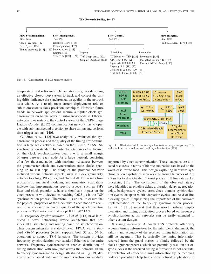
102 IEEE COMMUNICATIONS SURVEYS & TUTORIALS, VOL. 21, NO. 1, FIRST QUARTER 2019
Fig. 18. Classification of TSN research studies.
temperature, and software implementations, e.g., for designingan effective closed-loop system to track and correct the tim-ing drifts, influence the synchronization quality in the networkas a whole. As a result, most current deployments rely onsub-microseconds clock precision techniques. However, futuretrends in network applications require a tighter clock syn-chronization on to the order of sub-nanoseconds in Ethernetnetworks. For instance, the control system of the CERN LargeHadron Collider (LHC) communication network has to oper-ate with sub-nanosecond precision to share timing and performtime-trigger actions [140].
Gutiérrez et al. [112] have analytically evaluated the syn-chronization process and the quality of the timing error estima-tion in large scale networks based on the IEEE 802.1AS TSNsynchronization standard. In particular, Gutierrez et al. focusedon the clock synchronization quality with a small marginof error between each node for a large network consistingof a few thousand nodes with maximum distances betweenthe grandmaster clock and synchronized node clocks span-ning up to 100 hops. The study of the protocol behaviorincluded various network aspects, such as clock granularity,network topology, PHY jitter, and clock drift. The results fromprobabilistic analytical modeling and simulation evaluationsindicate that implementation specific aspects, such as PHYjitter and clock granularity, have a significant impact on theclock precision with deviations reaching 0.625 µs in the TSNsynchronization process. Therefore, it is critical to ensure thatthe physical properties of the clock within each node are accu-rate so as to ensure the overall quality of the synchronizationprocess in TSN networks that adopt IEEE 802.1AS.
2) Frequency Synchronization: Liß et al. [113] have intro-duced a novel networking device architecture that pro-vides ULL switching and routing based on synchronization.Their design integrates a state-of-the-art FPGA with a stan-dard x86-64 processor (which supports both 32 and 64 bitoperation) to support TSN functions. The system providesfrequency synchronization over standard Ethernet to the entirenetwork. Frequency synchronization enables distribution oftiming information with low-jitter across the network. In thefrequency synchronization design illustrated in Fig. 19, dat-apaths are enabled with one or more synchronous modules
Fig. 19. Illustration of frequency synchronization design supporting TSNwith clock recovery and network wide synchronization [113].
supported by clock synchronization. These datapaths are allo-cated resources in terms of bit rate and packet rate based on theworst-case traffic load. This design exploiting hardware syn-chronization capabilities achieves cut-through latencies of 2 to2.5 µs for twelve Gigabit Ethernet ports at full line rate packetprocessing [113]. The constituents of the observed latencywere identified as pipeline delay, arbitration delay, aggregationdelay, backpressure cycles, cross-clock domain synchroniza-tion cycles, datapath width adaptation cycles, and head-of-lineblocking cycles. Emphasizing the importance of the hardwareimplementation of the frequency synchronization process,Liß et al. [113] suggest that their novel hardware imple-mentation and timing distribution process based on frequencysynchronization across networks can be easily extended toother custom designs.
3) Timing Accuracy: Although TSN protocols offer veryaccurate timing information for the inter clock alignment, thevalidity and accuracy of the received timing information canstill be uncertain. That is, typically the timing informationreceived from the grand master is blindly followed by theclock alignment process, which can potentially result in out-of-sync clocks if the received timing information is not accurate.The detection of erroneous timing information by the receivingnode can potentially help time critical network applications to
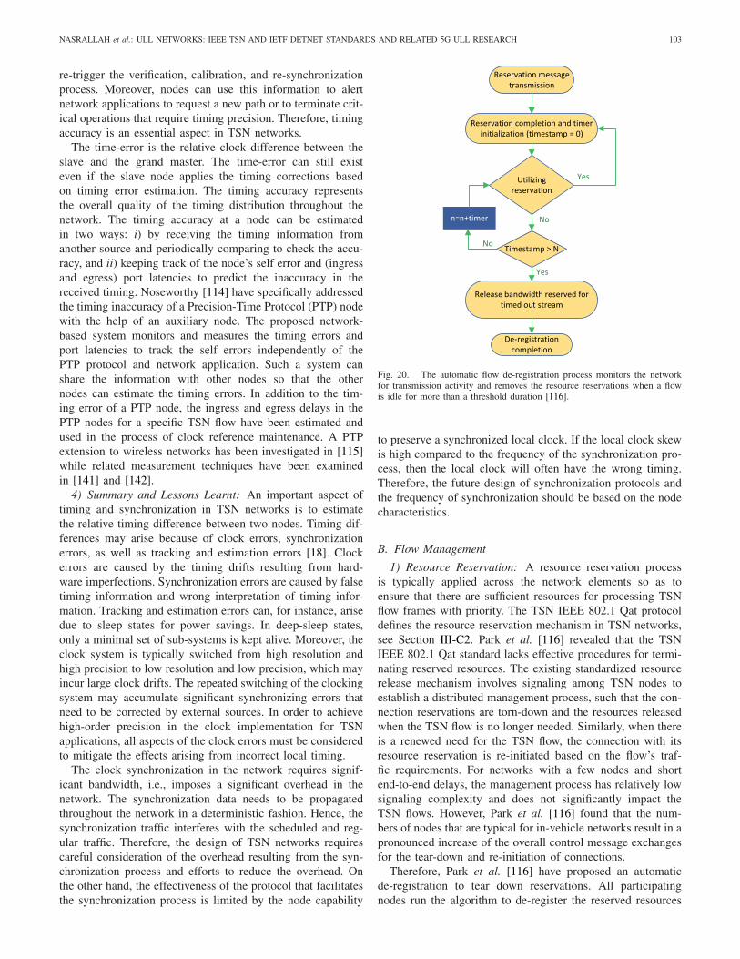
NASRALLAH et al.: ULL NETWORKS: IEEE TSN AND IETF DETNET STANDARDS AND RELATED 5G ULL RESEARCH 103
re-trigger the verification, calibration, and re-synchronizationprocess. Moreover, nodes can use this information to alertnetwork applications to request a new path or to terminate crit-ical operations that require timing precision. Therefore, timingaccuracy is an essential aspect in TSN networks.
The time-error is the relative clock difference between theslave and the grand master. The time-error can still existeven if the slave node applies the timing corrections basedon timing error estimation. The timing accuracy representsthe overall quality of the timing distribution throughout thenetwork. The timing accuracy at a node can be estimatedin two ways: i) by receiving the timing information fromanother source and periodically comparing to check the accu-racy, and ii) keeping track of the node’s self error and (ingressand egress) port latencies to predict the inaccuracy in thereceived timing. Noseworthy [114] have specifically addressedthe timing inaccuracy of a Precision-Time Protocol (PTP) nodewith the help of an auxiliary node. The proposed network-based system monitors and measures the timing errors andport latencies to track the self errors independently of thePTP protocol and network application. Such a system canshare the information with other nodes so that the othernodes can estimate the timing errors. In addition to the tim-ing error of a PTP node, the ingress and egress delays in thePTP nodes for a specific TSN flow have been estimated andused in the process of clock reference maintenance. A PTPextension to wireless networks has been investigated in [115]while related measurement techniques have been examinedin [141] and [142].
4) Summary and Lessons Learnt: An important aspect oftiming and synchronization in TSN networks is to estimatethe relative timing difference between two nodes. Timing dif-ferences may arise because of clock errors, synchronizationerrors, as well as tracking and estimation errors [18]. Clockerrors are caused by the timing drifts resulting from hard-ware imperfections. Synchronization errors are caused by falsetiming information and wrong interpretation of timing infor-mation. Tracking and estimation errors can, for instance, arisedue to sleep states for power savings. In deep-sleep states,only a minimal set of sub-systems is kept alive. Moreover, theclock system is typically switched from high resolution andhigh precision to low resolution and low precision, which mayincur large clock drifts. The repeated switching of the clockingsystem may accumulate significant synchronizing errors thatneed to be corrected by external sources. In order to achievehigh-order precision in the clock implementation for TSNapplications, all aspects of the clock errors must be consideredto mitigate the effects arising from incorrect local timing.
The clock synchronization in the network requires signif-icant bandwidth, i.e., imposes a significant overhead in thenetwork. The synchronization data needs to be propagatedthroughout the network in a deterministic fashion. Hence, thesynchronization traffic interferes with the scheduled and reg-ular traffic. Therefore, the design of TSN networks requirescareful consideration of the overhead resulting from the syn-chronization process and efforts to reduce the overhead. Onthe other hand, the effectiveness of the protocol that facilitatesthe synchronization process is limited by the node capability
Fig. 20. The automatic flow de-registration process monitors the networkfor transmission activity and removes the resource reservations when a flowis idle for more than a threshold duration [116].
to preserve a synchronized local clock. If the local clock skewis high compared to the frequency of the synchronization pro-cess, then the local clock will often have the wrong timing.Therefore, the future design of synchronization protocols andthe frequency of synchronization should be based on the nodecharacteristics.
B. Flow Management
1) Resource Reservation: A resource reservation processis typically applied across the network elements so as toensure that there are sufficient resources for processing TSNflow frames with priority. The TSN IEEE 802.1 Qat protocoldefines the resource reservation mechanism in TSN networks,see Section III-C2. Park et al. [116] revealed that the TSNIEEE 802.1 Qat standard lacks effective procedures for termi-nating reserved resources. The existing standardized resourcerelease mechanism involves signaling among TSN nodes toestablish a distributed management process, such that the con-nection reservations are torn-down and the resources releasedwhen the TSN flow is no longer needed. Similarly, when thereis a renewed need for the TSN flow, the connection with itsresource reservation is re-initiated based on the flow’s traf-fic requirements. For networks with a few nodes and shortend-to-end delays, the management process has relatively lowsignaling complexity and does not significantly impact theTSN flows. However, Park et al. [116] found that the num-bers of nodes that are typical for in-vehicle networks result in apronounced increase of the overall control message exchangesfor the tear-down and re-initiation of connections.
Therefore, Park et al. [116] have proposed an automaticde-registration to tear down reservations. All participatingnodes run the algorithm to de-register the reserved resources
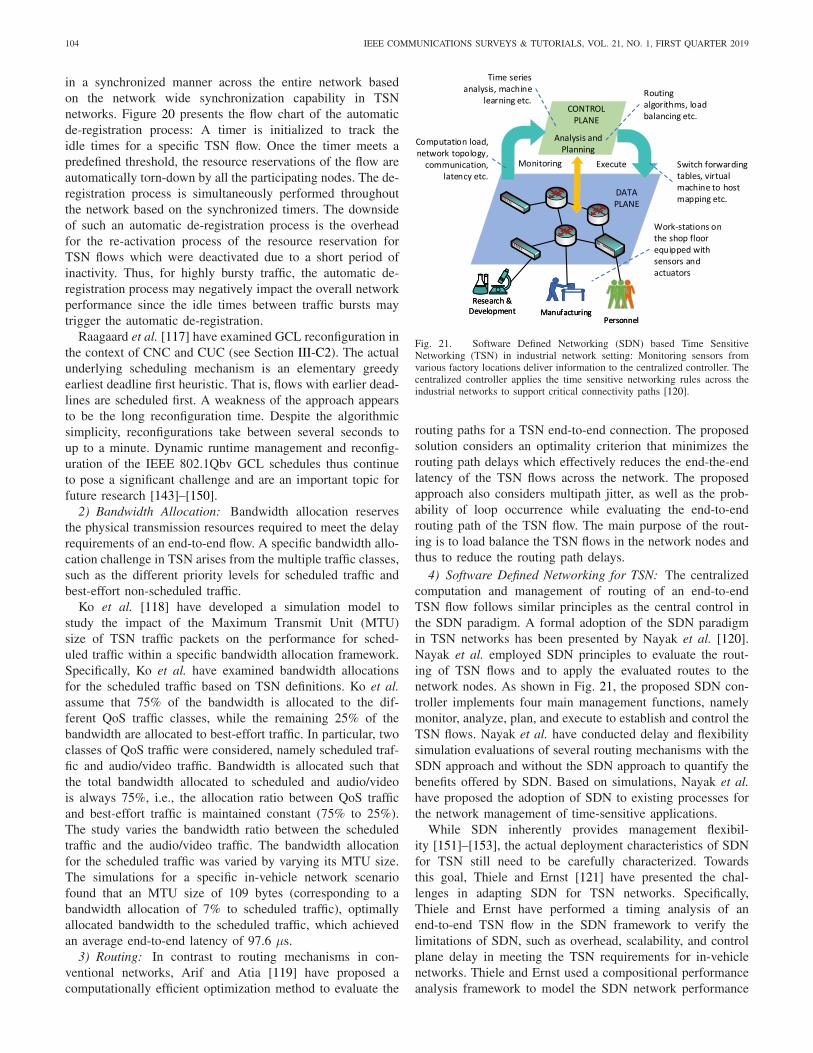
104 IEEE COMMUNICATIONS SURVEYS & TUTORIALS, VOL. 21, NO. 1, FIRST QUARTER 2019
in a synchronized manner across the entire network basedon the network wide synchronization capability in TSNnetworks. Figure 20 presents the flow chart of the automaticde-registration process: A timer is initialized to track theidle times for a specific TSN flow. Once the timer meets apredefined threshold, the resource reservations of the flow areautomatically torn-down by all the participating nodes. The de-registration process is simultaneously performed throughoutthe network based on the synchronized timers. The downsideof such an automatic de-registration process is the overheadfor the re-activation process of the resource reservation forTSN flows which were deactivated due to a short period ofinactivity. Thus, for highly bursty traffic, the automatic de-registration process may negatively impact the overall networkperformance since the idle times between traffic bursts maytrigger the automatic de-registration.
Raagaard et al. [117] have examined GCL reconfiguration inthe context of CNC and CUC (see Section III-C2). The actualunderlying scheduling mechanism is an elementary greedyearliest deadline first heuristic. That is, flows with earlier dead-lines are scheduled first. A weakness of the approach appearsto be the long reconfiguration time. Despite the algorithmicsimplicity, reconfigurations take between several seconds toup to a minute. Dynamic runtime management and reconfig-uration of the IEEE 802.1Qbv GCL schedules thus continueto pose a significant challenge and are an important topic forfuture research [143]–[150].
2) Bandwidth Allocation: Bandwidth allocation reservesthe physical transmission resources required to meet the delayrequirements of an end-to-end flow. A specific bandwidth allo-cation challenge in TSN arises from the multiple traffic classes,such as the different priority levels for scheduled traffic andbest-effort non-scheduled traffic.
Ko et al. [118] have developed a simulation model tostudy the impact of the Maximum Transmit Unit (MTU)size of TSN traffic packets on the performance for sched-uled traffic within a specific bandwidth allocation framework.Specifically, Ko et al. have examined bandwidth allocationsfor the scheduled traffic based on TSN definitions. Ko et al.assume that 75% of the bandwidth is allocated to the dif-ferent QoS traffic classes, while the remaining 25% of thebandwidth are allocated to best-effort traffic. In particular, twoclasses of QoS traffic were considered, namely scheduled traf-fic and audio/video traffic. Bandwidth is allocated such thatthe total bandwidth allocated to scheduled and audio/videois always 75%, i.e., the allocation ratio between QoS trafficand best-effort traffic is maintained constant (75% to 25%).The study varies the bandwidth ratio between the scheduledtraffic and the audio/video traffic. The bandwidth allocationfor the scheduled traffic was varied by varying its MTU size.The simulations for a specific in-vehicle network scenariofound that an MTU size of 109 bytes (corresponding to abandwidth allocation of 7% to scheduled traffic), optimallyallocated bandwidth to the scheduled traffic, which achievedan average end-to-end latency of 97.6 µs.
3) Routing: In contrast to routing mechanisms in con-ventional networks, Arif and Atia [119] have proposed acomputationally efficient optimization method to evaluate the
Fig. 21. Software Defined Networking (SDN) based Time SensitiveNetworking (TSN) in industrial network setting: Monitoring sensors fromvarious factory locations deliver information to the centralized controller. Thecentralized controller applies the time sensitive networking rules across theindustrial networks to support critical connectivity paths [120].
routing paths for a TSN end-to-end connection. The proposedsolution considers an optimality criterion that minimizes therouting path delays which effectively reduces the end-the-endlatency of the TSN flows across the network. The proposedapproach also considers multipath jitter, as well as the prob-ability of loop occurrence while evaluating the end-to-endrouting path of the TSN flow. The main purpose of the rout-ing is to load balance the TSN flows in the network nodes andthus to reduce the routing path delays.
4) Software Defined Networking for TSN: The centralizedcomputation and management of routing of an end-to-endTSN flow follows similar principles as the central control inthe SDN paradigm. A formal adoption of the SDN paradigmin TSN networks has been presented by Nayak et al. [120].Nayak et al. employed SDN principles to evaluate the rout-ing of TSN flows and to apply the evaluated routes to thenetwork nodes. As shown in Fig. 21, the proposed SDN con-troller implements four main management functions, namelymonitor, analyze, plan, and execute to establish and control theTSN flows. Nayak et al. have conducted delay and flexibilitysimulation evaluations of several routing mechanisms with theSDN approach and without the SDN approach to quantify thebenefits offered by SDN. Based on simulations, Nayak et al.have proposed the adoption of SDN to existing processes forthe network management of time-sensitive applications.
While SDN inherently provides management flexibil-ity [151]–[153], the actual deployment characteristics of SDNfor TSN still need to be carefully characterized. Towardsthis goal, Thiele and Ernst [121] have presented the chal-lenges in adapting SDN for TSN networks. Specifically,Thiele and Ernst have performed a timing analysis of anend-to-end TSN flow in the SDN framework to verify thelimitations of SDN, such as overhead, scalability, and controlplane delay in meeting the TSN requirements for in-vehiclenetworks. Thiele and Ernst used a compositional performanceanalysis framework to model the SDN network performance

NASRALLAH et al.: ULL NETWORKS: IEEE TSN AND IETF DETNET STANDARDS AND RELATED 5G ULL RESEARCH 105
for TSN. The SDN deployment requires a centralized con-troller for the global management of the TSN network fromflow establishment to tear-down. The placement of the con-troller among the TSN nodes can be challenging since thecontrol signalling communication between nodes and con-troller can span across the entire network. Each TSN flowestablishment process requires the exchange of control mes-sages between a TSN node and the controller. As the numbersof TSN nodes and flows increase, the overhead due to con-trol message exchanges could increase, affecting the overallTSN performance. Moreover, the flow setup process requiresthe TSN node to request the flow rules from the SDN con-troller which can increase the flow setup time as compared toa static non-SDN scenario. Therefore, to determine the fea-sibility of SDN for in-vehicle TSN networks an analyticalformulation was verified through simulations. The simulationresults demonstrate that the worst-case SDN network con-figuration delay is 50 ms, which is typically tolerable foradmission control and fault recovery in conventional Ethernetnetworks. A related SDN based control plane architecture hasrecently been proposed in [154].
5) Summary and Lessons Learnt: In addition to dynamicflow establishment based on current network characteristics,flow management ensures that TSN networks preserve thetime-sensitive characteristics, such as low end-to-end delay,when the network characteristics, such as topology and numberof nodes, change. The adaptability of the network to changes innetwork characteristics is an important network design aspectthat needs to be examined in detail in future research. Thisfuture research needs to address the control plane as well asthe data plane.
Currently, IEEE 802.1Qcc has centralized management, butdoes not preclude distributed management. The TSN TGhas started the process of chartering a project to standardizeRAP, see Section III-C4, which uses distributed management.Generally, centralized management can reduce the traffic over-head and reduce the management complexity. The detailedinvestigation of the tradeoffs between centralized and dis-tributed management is an important direction for futureresearch.
The static allocation of link resources to a TSN flow canresult in low network efficiency. Dynamic link resource alloca-tion provides more efficiency and flexibility. More specifically,a flow management technique can be implemented to sta-tistically multiplex several flows sharing common networkresources, while the worst-case flow performance is stillbounded by a maximum prescribed value. A pitfall that needsto be carefully addressed is the network complexity in devel-oping and deploying flow management techniques in actualnetworks. SDN may be a promising technology for the man-agement of dynamic resource allocation in TSN networks.SDN also provides an inherent platform to design advancedTSN flow management mechanisms, such as admission controland security mechanisms.
C. Flow Control
The overall temporal characteristics of a TSN flow aredictated by the flow control mechanisms that are applied in
the intermediate nodes. The flow control mechanisms imple-mented at each TSN node directly impact the process of frametraversal through each node that a particular flow is definedto pass through. A variety of flow control mechanisms areemployed in the intermediate nodes before an enqueued frameis scheduled for transmission over the physical link. The mostcritical flow control mechanisms in TSN nodes are trafficshaping as well as scheduling and preemption.
Traffic shaping limits the traffic rate to a maximum allowedrate, whereby all traffic exceeding the maximum allowed rateis buffered and scheduled for transmissions at an availableopportunity. (In contrast, traffic policing simply drops theexceeding traffic.) The downside of traffic shaping is queu-ing delay, while the downside of policing is that excess framedropping can affect the TCP transmission windows at thesender, reducing the overall network throughput.
1) Traffic Shaping: Control-Data Traffic (CDT) is the TSNtraffic class for transmissions of control traffic with the shortestpossible delay. In addition to the CDT class, TSN distinguishestraffic class A and class B. Collectively, these traffic classesare shaped by the traffic shapers in the TSN nodes to meetthe delay requirements. The traffic shapers ensure that i) theCDT is allocated resources with strict priority, ii) the TSNtraffic is isolated from the regular traffic, and iii) the waittimes for enqueued frames are bounded. Towards these goals,various traffic shaping methods have been standardized, seeSection III-D, in order to satisfy the requirements of the flowsbased on their traffic classes.
a) Shaping analysis: Thangamuthu et al. [122] haveconducted a detailed comparison of the standard TSN traf-fic shaping methods. In particular, Thangamuthu et al. havecompared the burst limiting shaper (BLS, a variation of CBS,which was considered in research but not incorporated intothe TSN standard), the time aware shaper (TAS), and theperistaltic shaper (PS), see Section III-D. The simulationsshow that for typical 100 Mbps Ethernet network deploymentsthe in-vehicle delay requirements are met for most applica-tions, except for applications with strict delay requirements.Therefore, additional ULL mechanisms are recommended, inaddition to the traffic shaping, to satisfy strict applicationrequirements. Complementarily, Thiele et al. [155], [156], andMigge et al. [157] have conducted a formal timing analysis andworst-case latency analysis of the different shapers for an auto-motive Ethernet topology, while an avionics context has beenconsidered in [158]. Moreover, general latency and backlogbounds have recently been derived in [159]–[165]. As alterna-tive to CBS and TAS shaping, a pre-shaping approach at thesenders has been explored in [166]. A complementary analy-sis of the ATS shaper has bee conducted in [167]. Pre-shapinghas been found to be effective for a low number of hops.However, the pre-shaping effectiveness decreases with increas-ing hop count. Also, pre-shaping does not protect the shapedtraffic flows from other unshaped or misbehaving flows in thenetwork. The wireless fronthaul context, see Section VII-A1,has been considered in [168].
b) Traffic shaping overhead: Traffic shaping, in particu-lar the TAS can significantly impact the configuration overheadthroughout the network, especially for temporary (short lived)

106 IEEE COMMUNICATIONS SURVEYS & TUTORIALS, VOL. 21, NO. 1, FIRST QUARTER 2019
TSN flows. Typically, the TSN flows that originate from plug-and-play devices attached to the TSN network are temporaryin nature. The transmission schedule for TAS gate control mustbe evaluated and maintained at each traversed TSN node cor-responding to each temporary flow. The schedule informationat each node is generated and managed as a network config-uration. These network configurations must be applied acrossthe network to establish an end-to-end TSN flow. The tempo-rary TSN flows resulting from plug-and-play connections cancreate a deluge of management traffic overhead.
To address this overhead issue, Farzaneh and Knoll [123]have presented an ontology based automatic configurationmechanism. Application management service and TSN man-agement service entities coordinate the connection establish-ment and tear-down procedures, managing the control planeactions for the TSN network. A TSN knowledge database isimplemented to track and manage new, existing, and previousconnections. For each connection, QoS requirements, assign-ments, and source details, such as port, related topics anddevices are identified and analyzed to build an ontology ofTSN flows corresponding to an application and device. Thus,whenever the plug-and-play event for a specific device occursin the network, the TSN configurations are automaticallyretrieved and applied, lowering the overhead compared to theconventional connection management scheme. Although theautomatic configuration mechanism is similar to the princi-ples of SDN, Farzaneh and Knoll have discussed the processbased automatic configuration mechanism independently ofSDN. Nevertheless, the ontology based automatic configura-tion mechanism can be easily adapted to SDN by implement-ing the proposed application management service and TSNmanagement functions as an SDN application.
2) Scheduling:a) TTEthernet vs. TSN: Craciunas and Oliver [124] have
presented an overview of scheduling mechanisms for Time-Triggered Ethernet (TTEthernet) [169]–[171] and TSN. Inthe TTEthernet switch, the incoming frames for an outgoingegress port are temporarily stored in a buffer, and wait for thescheduler to assign a transmission-slot based on the precom-puted schedule. In contrast, the incoming frames in TSN aredirectly inserted into priority queues, and these priority queuesare served based on prescribed schedules. The fundamentaldifference between TTEthernet and TSN is the schedulingprocedure, whereby the TTEthernet buffer is served based onglobal static scheduling information, i.e., a tt-network-scheduleassigned to meet the end-to-end delay requirements. In con-trast, TSN employs a dynamic schedule local to each nodefor control frame transmissions from priority queues. TSNswitches may be synchronized to network timing and can pre-empt an ongoing lower priority transmission, which is notpossible in a TTEthernet switch. Thus, the deployment ofTSN switches as opposed to TTEthernet switches can improvesupport for delay critical applications. However, the implemen-tation cost and complexity (due to synchronization) of TSN istypically higher than for TTEthernet.
b) Control traffic scheduling: Bello [125] have presentedan overview of TSN standards and examined the scheduling ofcontrol traffic flows in intra-vehicular Ethernet networks. More
specifically, Bello focused on the IEEE 802.1Qbv standardfor scheduled traffic. Bello have implemented the scheduledtraffic mechanism for automotive connectivity applications byutilizing the time-sensitive properties of TSN. In particular,flow prioritization has been used to prioritize the control trafficflows over regular data flows. The traffic flows are separatedinto multiple priority queues and scheduling procedures areapplied across the queues. Bello [125] developed a simulationmodel for an automotive network to study the behaviors ofTSN supported network modules. The simulation evaluationsindicated significant latency reductions by up to 50% for thecontrol traffic flows, i.e., the scheduled traffic flows, comparedto non-scheduled traffic. A limitation of the Bello [125] studyis that it considered only the automotive network domain anddid not consider the wider applicability and potential of TSN.
c) Optimization based scheduling: An important short-coming of the IEEE 802.1Qbv standard, which defines thetransmission of scheduled traffic in TSN, is that there are nospecific definitions of algorithms to determine the transmissionschedule of frames on a link. In addition, the IEEE 802.1Qbvstandard enforces a time spacing, i.e., guard bands, betweenthe scheduled traffic types. The guard bands isolate scheduledtraffic belonging to a specific class from other traffic classes,including the best-effort traffic class. A critical pitfall in theIEEE 802.1Qbv standard is that as the number traffic classesincreases, there can potentially be a large number of guardband occurrences during the traffic transmissions over the link.Traffic schedules with frequent guard bands waste bandwidthand can contribute to latency increases. Hence, an importantfuture work direction is to develop traffic transmission sched-ules with reduced numbers of guard band occurrences in orderto prevent wasted bandwidth and to keep latencies low.
Dürr and Nayak [126] have modeled TSN scheduling as ano-wait job-shop scheduling problem [172]. Dürr et al. thenhave adapted the Tabu search algorithm [173]–[175] to effi-ciently compute optimal TSN transmission schedules whilereducing the occurrences of guard bands. The simulationevaluations indicate that the proposed algorithm can com-pute the near-optimal schedules for more than 1500 flows oncontemporary computing systems while reducing the guardband occurrences by 24% and reducing the overall end-to-endlatency for TSN flows. With the minimal duration of guardbands, see Section IV-C3, the receivers have to be activelysynchronized for the correct reception of TSN frames. Theexistence of guard bands in the traffic flows provides an inher-ent secondary synchronization for the receivers. However, itshould be noted that the implementation of such optimizationalgorithms can increase the network node complexity as wellas protocol operations, increasing the overall operational costof the device. These scheduling principles have been furtherdeveloped in [104] towards the incremental addition of newflows.
Craciunas et al. [127] have examined the scheduling ofreal-time traffic, whereby the transmission schedules are com-puted through optimization methods. The constraints for theoptimization problem formulation are based on the general-ized TSN network configuration in terms of the characteristicsof the Ethernet frames, physical links, frame transmissions,

NASRALLAH et al.: ULL NETWORKS: IEEE TSN AND IETF DETNET STANDARDS AND RELATED 5G ULL RESEARCH 107
end-to-end requirements, and flow isolation. While consid-ering a comprehensive set of parameters, the optimizationproblem is modeled to compute transmission schedules inonline fashion (i.e., is frame arrival event driven) to achievelow latency and bounded jitter. While a complex optimizationproblem can provide a near optimal solution, it is also impor-tant to consider the required computation times Addressingthe complexity aspect, Craciunas et al. have proposed sev-eral extensions to the optimization process and outlined theimplications for the computation time. Craciunas et al. [127]have conducted simulation evaluations for various networkloads and configurations. The simulation results indicate thatan optimization process can be scalable while achieving thedesired level of scheduling benefits, i.e., bounded latencyand jitter for an end-to-end connection carrying real-timetraffic. Craciunas et al. have further developed this optimalscheduling problem in [176] and [177]. A related schedul-ing approach based on a graphical model has recently beenexamined by Farzaneh et al. [128], while a recent study byKentis et al. [178] has examined the impact of port congestionon the scheduling.
d) Joint routing and scheduling: TSN frame transmis-sions out of the queues can be controlled through gating (seeSection III-D2), whereby a predefined event triggers the gateto transmit a frame from a queue according to a prescribedscheduling policy. With event triggering, the frame transmis-sions follow the predefined time triggered pattern, resultingin so-called time triggered traffic [92], [170], [179], [180].Pop et al. [129] have designed a joint routing and schedulingoptimization that evaluates the time trigger events to mini-mize the worst-case end-to-end frame delay. The time triggerschedule is based on an optimization problem formulatedwith integer linear programming. The proposed optimizationproblem comprehensively considers the network topology aswell as time trigger flows and AVB flows. The time triggerflows follow the shortest route, while AVB flows follow agreedy randomized adaptive search approach. Simulation eval-uations indicate that the compute time to evaluate the timetriggered scheduling and AVB routing optimization is accept-able as compared to the timing of the frame flows. A limitationof the approach by Pop et al. is that the optimizations are notscalable and flexible when there are changes in the proper-ties of network infrastructures, e.g., topology changes. Whenthere are such network infrastructure changes, then the entireoptimization process must be reconfigured. The recent relatedstudy by Smirnov et al. [130] has focused on mixed criticalitylevels while the study by Mahfouzi et al. [131] has focusedon the stability aspects of joint routing and scheduling.
e) Impact of traffic scheduling: Although TSN networksprovide a pathway to achieve ULL through enhancements tothe existing Ethernet standards, the benefits are limited toTSN flows as opposed to best-effort traffic. That is, in caseof mixed transmissions, where the TSN defined transmissionsare multiplexed with non-scheduled best effort traffic trans-missions, there are no guarantees for the effective behaviorof the non-scheduled best-effort traffic. If there are require-ments for the non-scheduled traffic, such as a hard deadlinefor frame delivery in an end-to-end connection, the application
can be severely affected due to the interference from thescheduled TSN traffic. The behavior characterization of non-scheduled traffic can be challenging and unpredictable dueto the interference from scheduled TSN traffic. Therefore,Smirnov et al. [132] have provided a timing analysis to studythe uncertainty of critical non-scheduled traffic in presenceof scheduled TSN traffic interference. The challenge in thecharacterization of scheduled interference is to consider allpossible traffic scenarios, such as all possible scheduling types,resulting in long computation times. Smirnov et al. proposean approach to integrate the analysis of worst-case sched-uled interference with traditional end-to-end timing analysisapproaches to reduce the computation times. Such an inte-grated approach can estimate an upper bound on the scheduledinterference for various scheduling types, and the evaluationsshow significant computation time reductions.
A complementary study by Park et al. [133] has investi-gated the performance of scheduled traffic as opposed to thenon-scheduled traffic. Park et al. preformed extensive sim-ulations focusing on TSN to verify whether the end-to-endflow requirements are impacted by increasing numbers of TSNnodes in the presence of non-scheduled traffic. The simula-tions employed the general network wide synchronous event-triggered method for frame transmissions in TSN networks.The simulations for an in-vehicle network based on the eventtriggered scheduling for various traffic types show that thedelay requirements of control traffic can be successfully metfor up to three hops. However, the scheduled traffic needs tobe transferred within at most five hops to meet the typical100 µs delay requirement for critical control data in-vehiclenetworks.
At a given TSN node, the events to trigger an action thatis then utilized for traffic scheduling can either be generatedby a processing unit within the TSN node or by an exter-nal control entity. With the development and proliferationof SDN, future research can develop various event genera-tion techniques based on the centralized SDN control andmanagement. The generated events can trigger various TSNspecified actions, such as frame transmissions, frame drop-ping, or frame preemption, enabling new applications forSDN control and management. To the best of our knowledge,event triggering methods based on SDN have not yet beeninvestigated in detail, presenting an interesting direction forfuture research. However, SDN based management of TSNhas already proposed and we discuss the applicability of SDNfor managing TSN flows in Section IV-B4.
While scheduled TSN transmissions provide low latencyfor prioritized traffic, lower-priority traffic which is alsoTSN scheduled can be significantly affected by higher pri-ority traffic. In order to advance the understanding of thebehaviors of traffic shapers on low-priority TSN traffic,Maxim and Song [181] have analyzed the delay of Ethernetframes that are scheduled according to a hierarchical CBS orTAS in TSN switches. The evaluations by Maxim and Songindicate that the traffic scheduling for higher priority TSNflows can potentially result in traffic burstiness for lower pri-ority TSN flows, increasing the overall delay for the lowerpriority traffic. This is because, long bursts of higher priority
108 IEEE COMMUNICATIONS SURVEYS & TUTORIALS, VOL. 21, NO. 1, FIRST QUARTER 2019
traffic starve the scheduling opportunities for lower priorityframes, leading to the accumulation of low priority traffic. Inaddition to the static scheduling order, Maxim and Song havealso studied the effects of changing the scheduling orders interms of end-to-end delay for both higher and lower prioritylevels. The formal worst-case delay analysis and simulationresults indicate that low priority traffic is severely affected bythe scheduled higher priority traffic. Simulations of an auto-motive use-case indicate a worst-case delay for the prioritizedtraffic of 261 µs, while the worst-case delay for low prioritytraffic is 358 µs.
3) Preemption:a) Preemption mechanism: Lee et al. [134] have exam-
ined the preemption mechanism (see Section III-D3) inconjunction with the TSN timing and synchronization char-acteristics to estimate the transmission properties of CDT andnon-CDT frames. In particular, Lee et al. have proposed toinsert a special preemption buffer into the transmission selec-tion module that operates across all the different queues atthe bottom in Fig. 10 to aid with the preemption mechanism.Lee et al. have then analyzed the timing dynamics of the pre-emption. Lee et al. note that in actual deployments there arelikely timing synchronization errors which impact the frameboundary calculations. Therefore, a minimum safety marginthat avoids collisions should be maintained while implement-ing the preemption mechanism. Lee et al. [134] advocate fora safety margin size of 20 bytes, accounting 5 bytes for anerror margin and 15 bytes for synchronization errors. The sim-ulation evaluations justify the impact of the synchronizationerrors on the safety margin duration and end-to-end delay.Related preliminary preemption analyses have been conductedin [182].
b) Preemption effect on non-CDT: Preemption prioritizesCDT frame transmissions over the transmission of regu-lar Ethernet frames. Thus, preemption of non-CDT trafficcan negatively impact the end-to-end characteristics of non-CDT traffic. In addition, low priority CDT frames can bepreempted by high priority CDT frames. Hence, the pre-emption process can impact the end-to-end delay differentlyfor the different priority levels even within the CDT traf-fic. Thiele and Ernst [135] have formulated an analyticalmodel to investigate the implications of preemption on theend-to-end delay characteristics of CDT and non-CDT traffic.Thiele et al. have compared standard Ethernet with preemp-tion (IEEE 802.1Q + IEEE 802.3br) and TSN Ethernet withtime triggered scheduling and preemption (IEEE 802.1Qbv+ IEEE 802.3br) with the baseline of standard Ethernet(IEEE 802.1Q) without preemption. The worst-case end-to-endlatency of CDT with preemption was on average 60% lowerthan for 802.1Q without preemption. Due to the CDT priori-tization, the worst-case latency of non-CDT traffic increasedup to 6% as compared to the baseline (802.1Q) due to theoverhead resulting from the preemption process. Hence, theimpact of preemption of non-CDT traffic is relatively minoras compared to the performance improvements for CDT traf-fic. Additionally, the latency performance of standard Ethernetwith preemption is comparable to that of Ethernet TSN withpreemption. Therefore, Thiele and Ernst [135] suggest that
standard Ethernet with preemption could be an alternative toTSN for CDT traffic. Standard Ethernet would be much eas-ier to deploy and manage than TSN, as TSN requires thedesign and maintenance of the IEEE 802.Qbv gate schedulingprocesses along with time synchronization across the network.
c) Preemption analysis and hardware implementation:Zhou et al. [136] conducted a performance analysis of frametransmission preemption. In particular, Zhou et al. adapteda standard M/G/1 queueing model to estimate the long runaverage delay of preemptable and non-preemptable frame traf-fic and evaluated the frame traffic through simulations. Thenumerical results from the adapted M/G/1 queueing modeland the simulations indicate that preemption is very effec-tive in reducing the frame delays for express non-preemptabletraffic relative to preemptable traffic; the average frame delaysof the express traffic are one to over three orders of mag-nitude shorter than for preemptable traffic. Zhou et al. havealso provided the VHDL design layout of the transmit unitand receive unit for frame preemption for an FPGA basedhardware implementation.
4) Summary and Lessons Learnt: Flow control mechanismsensure that intermediate nodes support the end-to-end behaviorof a TSN flow. Traffic shaping controls the frame transmis-sion over the egress port in a TSN switch. Each traffic shaperstrives to transmit a frame from a priority queue within theshortest possible deadline while minimizing the impact onthe transmissions from other queues. A finer resolution ofpriority levels, i.e., a higher number of priority levels pro-vides increasingly fine control over frame transmissions frommultiple queues. As a limiting scenario, an independent queuecan be implemented for each individual flow in a TSN node.However, such fine-grained prioritization would require exten-sive computation and memory resources in each TSN node. Toovercome this, virtual queues can be implemented by markingthe frames in a single queue, eliminating the need for a num-ber of queues equal to the number of TSN flows. Each markedframe can be scheduled based on the marking value. As lowpriority flows can potentially face long delays due to resourcestarvation from the scheduling of high priority flows, dynamic(i.e., changeable) priority values can be assigned to virtualqueues. Dynamic priorities can prevent prolonged delays forflows that were initially assigned low priority. The prioritylevels can be dynamically changed based on the wait time orthe total transit delay of a frame compared to a predefinedthreshold. Advanced dynamic priority techniques, such aspriority inversion, could be implemented such that the worst-case delay of low priority traffic is kept within prescribedlimits.
D. Flow Integrity
1) Fault Tolerance: The AVB task group was mainly intro-duced to add real-time capabilities to the best effort Ethernetservice. Industrial control networks expect more reliable andstricter QoS services as compared to best effort Ethernetnetwork service. Fault tolerance is a critical part of industrialnetworks. The general principle for enabling fault tolerance ina network is to introduce redundancy.
NASRALLAH et al.: ULL NETWORKS: IEEE TSN AND IETF DETNET STANDARDS AND RELATED 5G ULL RESEARCH 109
Following this general principle, TSN provides fault toler-ance through redundancy mechanisms, such as frame repli-cation and elimination as well as path control and reser-vations, see Section III-E. Kehrer et al. [137] have con-ducted research on possible fault-tolerance techniques forTSN networks. The main challenges associated with faulttolerance mechanisms in TSN networks are the restora-tion processes for end-to-end link failures while preservingthe network topology, i.e., without causing any significantbreak in continuous network connectivity. To address this,Kehrer et al. have compared two approaches: i) decoupledstream reservation and redundancy [183], and ii) harmonizedstream reservation and redundancy (which corresponds toIEEE 802.1CB).
In the decoupling approach, the stream reservation proto-col registers and reserves the streams independently of theredundancy requirements. This decoupled approach allows forarbitrary redundancy protocols to be utilized. In contrast, theharmonized approach integrates establishment of the reserva-tion and the redundancy requirements. More specifically, theIEEE 802.1Qca stream reservation protocol is coupled withthe IEEE 802.1CB frame duplication.
The main pitfall to avoid is to understand the applicationrequirements in terms of flexibility before choosing the redun-dancy approach. Specific industrial automation networks mayhave peculiar reliability requirements that may be more flex-ibly met with the decoupled approach. On the other hand,the decoupled approach has a higher protocol overhead andrequires more network bandwidth due to the distributed andindependent mechanisms along with the lack of coordinationbetween stream reservation and redundancy, as opposed to theintegrated approach. A related fault tolerance approach basedon redundant packet transmissions has been examined in [138]while a mixing of temporal and spatial redundancy has beenproposed in [184].
2) Summary and Lessons Learnt: Failure recovery andfault tolerance are key aspects of reliable network design.However, to date there has been only very scant researchto address the critical challenges of resource reservationfor fault tolerance while considering ULL requirements.Future research has to investigate the wide range of trade-offs and optimizations that arise with reliability throughframe replication. For instance, high priority flows couldhave reservations of dedicated resources, while low prior-ity flows could share a common reserved resource. Thededicated resources would enable the instantaneous recov-ery of the high priority TSN flows; albeit, at the expenseof a slight reduction of the overall network efficiency dueto the redundancy. In the event of failure for a low prior-ity traffic flow, the connection could be reestablished witha new flow path considering that the flows can toleratedelays on the order of the connection reestablishment time.Centralized SDN management can also provide the flexibilityof dynamic path computation and resource reallocation in theevent of failures. Therefore, the area of flow integrity requiresimmediate research attention to design and evaluate theperformance of efficient recovery processes based on prioritylevels.
E. General TSN Research Studies
TSN is being widely adopted in critical small-scale closedautomotive and industrial networks to establish reliable ULLend-to-end connections. However, a key TSN limitations isexactly this focus on closed networks, e.g., in-vehicle networksand small-scale robotic networks. The network applicationsrunning in robots and in in-vehicle networks often involve sig-nificant interactions with external non-TSN networks. Roboticand vehicular network applications require a tight integrationwith mobility handling procedures by the external network.If advanced network features, such as mobility, are not prop-erly supported in the external network, then the TSN benefitsare fundamentally limited to small-scale closed networks.Therefore, smooth interoperability between TSN and dif-ferent external networks is essential for TSN operation inheterogeneous network scenarios. Ideally, the connectivitybetween TSN and non-TSN networks should be able toaccommodate similar characteristics as TSN to ensure theoverall end-to-end connection requirements in heterogeneousdeployments.
1) V2X Communication: Lee and Park [185] have proposediTSN, a new methodology for interconnecting multiple TSNnetworks for large-scale applications. The iTSN methodol-ogy utilizes wireless protocols, such as IEEE 802.11p, forthe inter-networking between different TSN networks. In par-ticular, the sharing of global timing and synchronizationinformation across the interconnected network is importantfor establishing a common timing platform to support TSNcharacteristics in the external networks. The iTSN networkuses the IEEE 802.11p WAVE short message protocol toshare the timing information between different TSN networks.Critical rapid alert messages can be prioritized not only withina given TSN network, but also across multiple intercon-necting networks. Thus, the iTSN methodology enables, forinstance, vehicular networks to transmit safety critical mes-sages to control nodes, e.g., Road Side Units (RSUs) [186],with delays on the order of microseconds in a heterogeneousdeployment. Through the adoption of such reliable inter-connectivity techniques, the vehicle braking safety distancecan be achieved in much shorter (microseconds) time spansthan the currently feasible range of milliseconds. Overall, TSNand an interconnecting technique, such as iTSN, can cre-ate a communication platform for safe autonomous drivingsystems.
2) Network Modeling: Although TSN standards havereceived significant attention in networks for automotive driv-ing, a major challenge in network deployment is managingthe complexity. As automotive driving technology progresses,more requirements are imposed on the existing in-vehiclenetwork infrastructure. As the number of sensors increasesin an in-vehicle network, the increasing connectivities andbandwidth requirements of the sensors should be correspond-ingly accommodated in the network planning. However, thedynamic changes in the network requirements for an in-vehiclecontrol system could require a more extensive network infras-tructure, resulting in higher expenditures. Considering thecomplexities of automotive networks, Farzaneh et al. [187]have proposed a framework to analyze the impact of adding

110 IEEE COMMUNICATIONS SURVEYS & TUTORIALS, VOL. 21, NO. 1, FIRST QUARTER 2019
new sensors to an existing infrastructure that supports criti-cal applications. In particular, the network configuration thatfulfills all the requirements, including newly added sensors,must be dynamically evaluated and implemented. Towards thisend, the Farzaneh et al. [187] framework involves a designand verification tool based on a Logic Programming (LP)method to support the reconfiguration and design verifica-tion processes for an in-vehicle TSN network. The proposedframework consists of comprehensive logical facts and rulesfrom which a user can query the database with the require-ments to obtain configurations that satisfy the requirements.A key characteristic of the proposed approach is that thenetwork modeling process considers the most accurate log-ical facts and rules of the TSN applications and require-ments to obtain an efficient configuration and verificationprocess.
3) TSN Simulation Framework: Heise et al. [188] havepresented the TSimNet simulation framework to facilitate thedevelopment and verification of TSN networks. TSimNet wasprimarily implemented to verify industrial use-cases in TSNnetworks. The simulation framework is based on OMNeT++,whereby the non time-based features, such as policy enforce-ment and preemption are implemented in a modular fashionto increase the flexibility of designing new network mecha-nisms suitable for industrial networks. For instance, the initialevaluation of the simulation framework for frame preemp-tion mechanisms indicates that the end-to-end latency can beincreased if the network is not configured in an optimizedway for critical functions, such scheduling and traffic shap-ing. Heise et al. have evaluated the computational cost ofthe TSimNet framework for various network function simu-lations, such as policing, recovery, and preemption in termsof CPU and memory requirements. The simulation frameworkalso features Application Programming Interfaces (APIs) forTSN mechanisms that do not require time synchronization,such as stream forwarding, per-stream filtering, as well asframe replication and recovery. APIs can be invoked by thesimulation framework through a profile notification. The basicframework modules also include the TSimNet Switch Model,which can identify streams based on MAC, VLAN, and/or IPaddresses, while the TSimNet Host Model implements com-plex functions, such as ingress and egress policy, as well astraffic shaping. Related simulation evaluations with OMNeT++have been reported in [189], while a TSN simulation modelbased the OPNET simulation framework has been presentedin [190].
4) Hardware and Software Design: Hardware and soft-ware component designs to support TSN functions, such asscheduling, preemption, and time-triggered event generationin TSN nodes require significant engineering and develop-ment efforts. Hardware implementations are highly efficientin terms of computational resource utilization and executionlatency but result in rigid architectures that are difficult toadapt to new application requirements. On the other hand, soft-ware implementations can flexibly adapt to new applicationrequirements, but can overload CPUs due to the softwariza-tion of network functions, such as time-triggered schedulingand hardware virtualization.
Groß et al. [191] have presented a TSN node architec-ture design where the time-sensitive and computationallyintensive network functions are implemented in dedicatedhardware modules to reduce the CPU load. The proposed hard-ware/software co-design approach flexibly allocates networkfunctions to be executed completely in hardware, completelyin software, or in both hardware and software based on thedynamic load. The flexible allocation is limited to networkfunctions that scale independently of the timing require-ments, such as the synchronization protocol. More specifically,Groß et al. have considered time-triggered transmissions,frame reception and timestamping, and clock synchroniza-tion. The hardware modules can produce the time-triggeredevents nearly jitter free, implement frame reception and time-stamping in real-time, and synchronize clocks with a highdegree of precision. Thus, the hardware modules improve theoverall TSN node performance compared to a software-onlyimplementation. The performance evaluations from a proto-type implementation based on a Virtex-6 FPGA showed asignificant reduction in the CPU load compared to a software-only implementation. Additionally, the precision of the time-triggered event generation in the hardware implementation wasimproved by a factor of ten compared to software triggeredevents.
5) Summary and Lessons Learnt: The general aspects ofTSN that determine the overall success of TSN designsand implementations are the interoperability with heteroge-neous network architectures, such as LANs, WANs, and corenetworks. Most of the research on TSN to date has focused onin-vehicle networks which are independent and isolated fromexternal networks. Another limitation of the TSN research fieldis the lack of a simulation framework that encompasses large-scale heterogeneous network architectures. Valid use casesthat include both localized and external network interactions,such as automotive driving, should be created and consideredin benchmark evaluations. Currently, the general use-case inmost TSN research studies is an in-vehicle network support-ing on-board sensor connectivity and audio/video transmissionfor infotainment. Future custom TSN simulation frameworksshould be based on networks that support next-generationapplications with localized and external network interactions,such as automotive driving. Similarly, the SDN based TSNmanagement could exploit hierarchical controller designs toextend the management from localized networks, such as in-vehicle networks, to external networks, such as vehicle-to-any(V2X) networks.
F. Discussion on TSN Research Studies
The TSN network infrastructure and protocols have to sup-port bounded end-to-end delay and reliability, to support basicfeatures related to critical applications in the IoT, medicine,automotive driving, and smart homes. TSN based solutionsfor addressing the requirements of these applications result incomplex network infrastructures supporting various protocols.Hence, simplified TSN network management mechanisms areessential to reduce the complexity while achieving the criticalneeds of the ULL applications.
NASRALLAH et al.: ULL NETWORKS: IEEE TSN AND IETF DETNET STANDARDS AND RELATED 5G ULL RESEARCH 111
The deterministic TSN network behavior has so far beengenerally applied to a closed network, i.e., a network span-ning only the scope of a particular application, for instance,in-vehicle networks. However, the connectivity to externalnetworks, such as cellular and WLAN networks, enhances thecapabilities of TSN networks. For instance, in automotive driv-ing, the application requirements can be controlled by weatherdata from the cloud or by sharing information with neighbor-ing TSN in-vehicle networks. Therefore, reliable, secure, andlow-latency communication between multiple TSN networksis essential to support a wide range of future applications. Thelack of TSN standards for connecting and communicating withexternal TSN and non-TSN networks is impeding the researchactivities in inter-operating networks and needs to be urgentlyaddressed. In summary, we identify the following main futuredesign requirements for TSN research:
i) Support for a wide range of applications spanning fromtime-sensitive to delay tolerant applications with flowlevel scheduling capabilities.
ii) Connectivity between multiple closed TSN architectures.iii) Flexible and dynamic priority allocations to ensure
bounded end-to-end latency for lower priority traffic.iv) Adoption of SDN for the centralized management of TSN
functions with a global network perspective.v) Efficient timing information sharing and accurate clock
design through self-estimation and correction of localclock skewness.
vi) Computationally efficient hardware and software designs.Generally, TDM can enforce a deterministic (100%) latency
bound, but the TDM average delay is typically somewhathigher than the statistical multiplexing average delay (andTDM has low utilization for bursty traffic). With proper admis-sion control, statistical multiplexing can provide statisticalguarantees for latency bounds [192], e.g., the probability forexceeding the delay bound can be very low, e.g., less than10−4 probability that the delay bound is violated. These rareoccurrences of violating the delay bound “buy” usually muchhigher utilization (throughput) than TDM and lower aver-age delay (for bursty data traffic) [193]–[197]. An interestingfuture research direction is to examine the tradeoffs betweendeterministic and probabilistic delay bound assurances indetail for ULL traffic served with TSN mechanisms.
V. DETNET STANDARDIZATION
In this section, we present a detailed overview of the cur-rent standardization of the IETF Deterministic Networking(DetNet) WG. The IETF DetNet WG collaborates with theIEEE 802.1 TSN TG to define a common architecture for lay-ers 2 and 3, whereby the TSN TG focuses on layer 2 bridgednetworks and the DetNet WG focuses on layer 3 routed seg-ments. Similar to the TSN goals, DetNet aims to supportdeterministic worst-case bounds on latency, packet delay vari-ation (jitter), and extremely low/zero packet loss. Moreover,both TSN and DetNet strive for high reliability and redun-dancy over disjoint paths targeted towards IACS real-timeapplications.
The charter of the DetNet WG is to specify an overall archi-tecture that standardizes the data plane and the Operations,Administration, and Maintenance (OAM) for layer 3 ULLsupport. This charter includes the time synchronization, man-agement, control, and security operations that enable multi-hoprouting. Moreover, the DetNet charter includes the vari-ous forms of dynamic network configuration (automated anddistributed as well as centralized and distributed) and themulti-path forwarding. In general, DetNet focuses on extend-ing the TSN data and control plane into the layer 3 domain,thus expanding the scope of TSN beyond LANs.
Since the DetNet WG has only been established recently(started in October 2014, and became a WG in October2015), no IETF RFCs exist yet. However, at the time of writ-ing this article, several IETF drafts have become availableand will be covered in the following subsections to pro-vide a comprehensive overview of the ongoing IETF DetNetstandardizations.
A. Flow Concept
Similar to the TSN TG, DetNet flows are specified by theirQoS classes. DetNet defines each flow’s QoS by 1) the max-imum and minimum end-to-end latency, and 2) the packetloss probability requirements [198]. DetNet strives to transportunicast and multicast ULL data flows for real-time appli-cations with extremely low packet loss. In essence, DetNetemulates point-to-point links over a packet switched network,where each link can be shared between multiple DetNet andnon-DetNet flows, each with varying flow requirements andproperties. A key aspect of DetNet flow control and manage-ment is ensuring that non-DetNet flows have no influence onDetNet flows. Maintaining each DetNet flow’s QoS is achievedthrough the mechanisms surveyed in this section.
1) DetNet Flow Types: Before introducing the DetNet flowtypes, we first give a brief overview of two main layers ofthe DetNet architecture stack model. The DetNet TransportLayer has an option to provide congestion protection (seeSection V-D). The DetNet Service Layer provides service pro-tection, e.g., through flow duplication (see Section V-E). Fourmain DetNet flow types have been identified [198]:
1) App-flow: The native data flow between the sourceand destination end systems within a DetNet enablednetwork.
2) DetNet-t-flow: The specific data flow format bound tothe transport layer within a DetNet enabled network.The DetNet-t-flow contains the specific data attributesthat provide features for congestion protection.
3) DetNet-s-flow: The specific data flow format bound tothe service layer within a DetNet enabled network. TheDetNet-s-flow contains the specific data attributes thatprovide features for replication and elimination functionssupporting service protection.
4) DetNet-st-flow: The specific data flow format that isbound to both the transport and service layers withina DetNet enabled network. The DetNet-st-flow signalsthe appropriate forwarding function utilizing both theservice and transport layer attributes.

112 IEEE COMMUNICATIONS SURVEYS & TUTORIALS, VOL. 21, NO. 1, FIRST QUARTER 2019
Fig. 22. Classification of DetNet Standardization.
2) DetNet Flow Identification: In contrast to a conventionalstrictly layered network architecture, DetNet nodes intention-ally violate “layering norms” so that lower layers can detectand become aware of higher layer flow types. This awarenessof the higher layer flow types helps to provide specific queu-ing, shaping, and forwarding services as flows are transportedacross multiple technology domains. However, violating thelayering norms creates new layering and re-layering complex-ities. Therefore, DetNet must provide a way to easily andcorrectly identify flows and their associated types. DetNet isarchitected to allow nodes within the network data plane todistinguish DetNet flows based on the flow ID and DetNetControl Word (CW), i.e., sequencing information, appendedin the packet header, whereby the CW is used for replicationand elimination purposes.
To achieve accurate flow detection and identification, theflow attribute mapping between layers and across technol-ogy domains has to be standardized. For each forwardingof a DetNet flow between different technology domains, therelay node (i.e., router) needs to acquire upper layer infor-mation related to the flow type and corresponding attributes.For example, when a DetNet flow is forwarded between twoLabel Switching Routers (LSRs) that interconnect differentLayer 2 bridged domains, then at each domain boundary, thehigher layer flow information is passed down to the node forcorrect forwarding. Three main forwarding methods are con-sidered in DetNet: 1) IP routing, 2) MPLS label switching,and 3) Ethernet bridging. For forwarding across technol-ogy domains, each DetNet App-flow packet is appended orencapsulated with multiple flow-IDs (IP, MPLS, or Ethernet).This enables DetNet routing and forwarding between differentand disparate IP and non-IP networks, essentially providingnetwork interoperability.
B. Flow Synchronization
The main objective of DetNet is to expand the TSN capa-bilities to layer 3 routing segments. DetNet relies heavily onthe services of the IEEE TSN TG mechanisms. Flow synchro-nization with respect to the DetNet flow architectural modelhas not been specifically addressed in [198]. Therefore, it islikely that DetNet will ensure timing synchronization betweenDetNet capable network entities (bridges, routers, and end
systems) through various existing synchronization techniquesand profiles, e.g., IEEE 802.1AS and IEEE 1588v2.
Applications in the mission critical latency traffic classrequire extremely low delay variations (jitter). High jittercan lead to packet loss downstream and in the worst-case,loss of human life in factory networks. DetNet strives tosupport minimal jitter by bounding the minimum and maxi-mum latency [198], which is challenging in large scale packetswitched networks. DetNet specifies jitter reduction throughtwo main principles: 1) sub-microsecond time synchroniza-tion between network entities, and 2) time-of-execution fieldsembedded within the application packets [198]. While no spe-cific specifications regarding time synchronization for DetNetnetwork devices exist, the DetNet WG have overall hintedat using other Standardization Development Organization’s(SDO), e.g., IEEE TSN’s 802.1AS methods, see Section III-B.
C. Flow Management
Flow management describes and specifies the mechanismsfor discovering and configuring node capabilities.
1) DetNet Configuration and YANG Model: In order forDetNet to enable seamless configuration and reconfigurationacross various DetNet enabled network entities, a uniform andscalable configuration model needs to be defined. The Internetdraft [199] defines distributed, centralized, and hybrid config-uration models, related attributes, and the YANG model forDetNet.
a) DetNet configuration model: Three configurationmodels have been introduced [199]: fully distributed, fullycentralized, and hybrid. For a fully distributed configurationmodel, UNI information is sent over a DetNet UNI proto-col, i.e., sent using the flow information model discussed inSection V-E. A distributed DetNet control plane propagates theUNI and configuration information to each data plane entity.In the centralized configuration model, the CUC sends theUNI information to the CNC, similar to the IEEE 802.1Qcccentralized configuration model, see Section III-C. For thehybrid configuration approach, a combination of distributedand centralized protocols within the control planes are usedto coordinate configuration information. The fully distributedand hybrid configuration models are not covered in [199] andare left for future work.
NASRALLAH et al.: ULL NETWORKS: IEEE TSN AND IETF DETNET STANDARDS AND RELATED 5G ULL RESEARCH 113
b) DetNet configuration attributes: Depending on theconfiguration model and control plane associated protocols(i.e., IGP and RSVP-TE, or CNC and CUC), different config-uration parameters or attributes are used. The following mainattributes have been defined for the centralized configurationmodel [199]:
1) DetNet Topology Attributes specify topology relatedattributes, such as the node type, whether it is PacketReplication and Elimination Function (PREF) capableor not, and the queueing management algorithm.
2) DetNet Path Configuration Attributes specify the net-worked path related attributes, such as the constraints(required min/max latency), and explicit routes using aPCE (with PREF).
3) DetNet Flow Configuration Attributes specify theDetNet flow attributes, such as the flow ID, priority,traffic specification, and encapsulation method.
4) DetNet Status Attributes specify the flow status feed-back attributes, such as the flow performance (delay,loss, policing/filtering), and the PREF status.
DetNet YANG Model: Similar to IEEE 802.1Qcp (seeSection III-C1), a DetNet YANG model has been defined [199]for the centralized configuration model to convey networkconfiguration parameters.
2) Network Resource Advertisement and Distribution: Tosupplement the DetNet Congestion Protection mechanisms(which are defined for DetNet as flow control mechanisms,including shaping, scheduling, and preemption), and to accu-rately provision network resources for DetNet flows, i.e.,admission control, each node (or central controller in a cen-tralized setup) needs to share and alert nearby networksof its (end system and/or transit node) capabilities [198]including:
1) System capabilities, e.g., shaping and queuing algorithmused, buffer information, and worst-case forwardingdelay
2) Dynamic state of the node’s DetNet resources3) Neighbor nodes and the properties of their relationships,
i.e., the properties of the links connecting them, e.g.,length and bandwidth.
How this information is carried over the control plane andthe implementation specification is not available nor standard-ized yet. However, with this information, PCE’s automatic pathinstallation (distributed or centralized) can handle each DetNetflow’s QoS requirement assuming that enough resources areavailable, which is enforced by admission control mechanismssimilar to the TSN SRP (MRP) protocols (see Section III-C2).
3) Centralized Path Setup: Similar to IEEE TSN’s cen-tralized management model (802.1Qcc, see Section III-C2),DetNet’s centralized path setup leverages PCEs and packetbased IP or non-IP network information dissemination toenable global and per-flow optimization across the DetNetenabled network. The DetNet WG [198] has addressed severalrelated key issues, such as the installation of the paths cor-responding to the received path computation (whether by theNetwork Management Entity (NME) or end systems), and howa path is set up, i.e., through direct interactions between theforwarding devices and the PCEs, or by installing the path on
one end of the path through source-routing or explicit-routinginformation [198].
4) Distributed Path Setup: The DetNet WG has developedinitial design specifications for a distributed path setup (similarto the 802.1Qat, 802.1Qca, and MRP signaling protocols) uti-lizing Interior-Gateway Protocol Traffic Engineering (IGP-TE)signaling protocols, defined in Section V-D, e.g., MPLS-TE,RSVP-TE, OSPF-TE, and ISIS-TE [198]. A key issue is howthe interactions and integration between layer 2 sub-networkpeer protocols for TE and path installation will be defined,since significant work has been accomplished by the IEEE802.1 TSN TG regarding distributed and centralized protocolson path and multi-path setup and signaling protocols.
5) Summary and Lessons Learned: Before controlling aDetNet flow, the node’s capabilities need to be distributedto the PCE in the control plane. To efficiently disseminatethe node capability information, a configuration and YANGmodel need to be standardized to allow for dynamic recon-figuration, management, and status collection in large scaleIP/non-IP based networks.
Additionally, as networks under the control of DetNetrelated services and mechanisms may become saturated withflows, effective admission control mechanism, e.g., similar tothe admission control mechanisms researched within the IETFIntServ framework [193]–[197], must be researched to operatewithin the DetNet framework. Based on the admission control,network resources must be managed such that ULL applica-tions/traffic that is marked with higher priorities than othertraffic can be allocated the appropriate resources.
D. Flow Control
While most control functions for DetNet flows followthe same principles used for IEEE TSN TG deterministicflows, key integration mechanisms and several differences areoutlined as follows.
1) DetNet Data Plane: To better understand how DetNetservices operate, we first provide a brief overview of theDetNet data plane. A DetNet capable network is com-posed of interconnected end systems, edge nodes, and relaynodes [198]. Transit nodes (e.g., routers or bridges) are usedto interconnect DetNet-aware nodes, but are not DetNet-aware themselves. Transit nodes view linked DetNet nodesas end points. DetNet is divided into two main layers:1) the DetNet service layer, and 2) the DetNet transportlayer. The DetNet service layer is the layer responsible forspecific DetNet services, such as congestion and service pro-tection, while the DetNet transport layer is responsible foroptionally providing congestion protection for DetNet flowsover paths provided by the underlying network [198]. Morespecifically, the service layer can apply specific services, suchas packet sequencing, flow replication/duplicate elimination,and packet encoding, while the transport layer can applycongestion protection mechanisms (through the underlayingsubnetworks, e.g., MPLS TE, IEEE 802.1 TSN, and OTN)and explicit routes. DetNets can have several hierarchicalDetNet topologies where each lower layer services the higher

114 IEEE COMMUNICATIONS SURVEYS & TUTORIALS, VOL. 21, NO. 1, FIRST QUARTER 2019
TABLE IIICANDIDATE PROTOCOLS FOR DETNET SERVICE AND TRANSPORT LAYERS. A PROMINENT DEPLOYMENT CANDIDATE
IS A UDP SERVICE LAYER OVER AN IP TRANSPORT LAYER
layers. Furthermore, DetNet nodes (end systems and interme-diary nodes) are inter-connected to form sub-networks. Thesesub-networks, e.g., Layer 2 networks, can support DetNet traf-fic through compatible services, e.g., IEEE 802.1 TSN orpoint-to-point Optical Transport Network (OTN) service in 5Gsystems [198].
There are currently various protocol and technology optionsunder consideration for DetNet service and transport layerprotocols. Table III provides an overview of these protocolcandidates for the DetNet service and transport layers, includ-ing a brief description of each protocol and the latency impacton a DetNet flow. Although no official solution has emergedyet for the DetNet data plane encapsulation at the networklayer, a couple of proposals exist to tackle this problem.According to Korhonen et al. [200], two of the most promi-nent deployment candidates for the data plane protocols areeither a UDP/TCP service layer over a native-IP (IPv6) trans-port layer or a PseudoWire-based (PW) [206] service layerover an MPLS Packet Switched Network (PSN) transportlayer. While many options exist for DetNet data encapsula-tion, it is imperative to test and discern the correspondingperformance overhead for each proposed DetNet node’s packetmanipulation technique.
2) DetNet Traffic Engineering: The IETF TrafficEngineering Architecture and Signaling (TEAS) WGconsiders Traffic Engineering (IE) architectures for packetand non-packet networks [208], essentially allowing networkoperators to control traffic traversing their networks. SinceDetNet operates with explicit paths, the DetNet WG hasdrafted a TE architectural design for DetNet utilizing similarmethodology as the Software Defined Networking (SDN)paradigm. The DetNet WG defines three main planes [198]:1) the (user) application plane, 2) the control plane, and3) the network plane. The network plane conforms with thespecification of the Internet Research Task Force (IRTF)
RFC 7426 [209] that details the structure and architecture ofthe SDN networking paradigm. This DetNet SDN approachshares similarities with the IEEE TSN’s 802.1Qcc man-agement scheme (see Section III-C2) and centralized SDNapproach.
a) Application plane: The collection of applications andservices that define the network behavior constitute the appli-cation plane. For example, network services, such as networktopology discovery, network provisioning, and path reserva-tion, are all part of network applications that can be utilizedthrough the application plane and can be accessed by a user-application interface or by other services through the serviceinterface [198]. Moreover, the DetNet WG has defined a useragent application for passing DetNet service requests fromthe application plane via an abstraction Flow ManagementEntity (FME) to the network plane. The management interfacehandles the negotiation of flows between end systems, whererequested flows are represented by their corresponding trafficspecification (Tspec), i.e., the flow characteristics. The appli-cations in the application plane communicate via the serviceinterface with the entities in the control plane
b) Control plane: The collection of functions responsi-ble for controlling (e.g., flow installation and processing in theforwarding plane) and managing (e.g., monitoring, configur-ing, and maintaining) network devices constitute the controlplane. The DetNet TE architecture utilizes the CommonControl and Measurement Plane (CCAMP) standardized bythe IETF CCAMP WG, where the aggregate control plane,i.e., the control and management planes, is distinctly splitbetween management and measurement entities within thecontrol plane. Additionally, the control plane leverages PCEsand NMEs. PCEs are considered the core of the control plane.Given the relevant information through the network interface,the PCEs compute the appropriate deterministic path that isinstalled in the network plane devices.

NASRALLAH et al.: ULL NETWORKS: IEEE TSN AND IETF DETNET STANDARDS AND RELATED 5G ULL RESEARCH 115
c) Network plane: The aggregate network plane consti-tutes the operational (control), forwarding (data), and parts ofthe applications plane aspects under the RFC 7426 standard.The network plane interconnects all the Network InterfaceCards (NICs) in the end systems and intermediate nodes(i.e., IP hosts and routers/switches). Additionally, UNIs andNetwork-to-Network (NNI) interfaces are used for TE pathreservation purposes. A network interface is used to enablecommunication between the network plane and the controlplane, whereby the control plane can describe and install thephysical topology and resources in the network plane.
In general, this DetNet TE architecture envisions a highlyscalable, programmable, and uPnP scheme, where networkfunctionality and configurations are easily implemented andextended.
3) Queuing, Shaping, Scheduling, and Preemption: Whileidentifying the appropriate data and control plane solutionsis imperative for correct operations in DetNet environments,flow control principles (e.g., queuing, shaping, scheduling,and preemption) must be defined to enable DetNet flows toachieve deterministic bounded latency and packet loss [198].Flow control usually involves admission control and networkresource reservation, i.e., bandwidth and buffer space allo-cation. However, a key aspect of reservation is to stan-dardize reservations across multi-vendor networks, such thatany latency in one system that differs in another system isaccounted for and handled appropriately.
DetNet flow control will accordingly leverage the IEEE802.1 TSN queuing and enhanced transmission and traf-fic shaping techniques surveyed in Section III-D. TheseTSN mechanisms include the credit-based shaper (802.1Q,Section 34), the time-gated or time-aware transmission selec-tion (802.1Qbv), the cyclic queuing and forwarding or peri-staltic shaper (802.1Qch), the asynchronous traffic shaper(802.1Qcr), and the preemption within bridges (802.1Qbu and802.3br). These techniques (except for packet preemption) canrelatively easily be implemented in DetNet networks and area focus of collaboration between the DetNet WG and theTSN TG.
4) QoS Performance Guarantees Between Synchronous andAsynchronous DetNet Flows: DetNet flows, similar to TSNflows, can be transmitted synchronously or asynchronously.Each method has advantages and disadvantages with respectto congestion protection. Synchronous DetNet flows traverseDetNet nodes that are closely time synchronized (e.g., bet-ter than one microsecond accuracy). The time synchronizedDetNet nodes can transmit DetNet flows belonging to dif-ferent traffic classes in a coordinated timely fashion, i.e.,based on repeated periodic schedules that are synchronizedbetween the DetNet nodes. This synchronized transmissionfollows the same principles as the TSN time-aware gatedmechanism (802.1Qbv) where buffers are shared based on thecoordinated time among the nodes. A main disadvantage ofsynchronous transmission is that there is a tradeoff betweenfine-grained time synchronized schedules and the requirednetwork resource allocation [198].
In contrast, asynchronous DetNet flows are relayed based onthe judgment of a given individual node. More specifically, the
node assumes the worst-case latency interference among thequeued DetNet flows and characterizes flows based on threeproperties:
1) The maximum packet size of each DetNet flow2) The observational interval, i.e., the time a DetNet flow
is occupying the resource3) The maximum number of transmissions during the
observational interval.Based on the DetNet packet properties and the various
header fields resulting from the employed protocol stack, thetransmission control limits the DetNet flow’s transmissionopportunities to a prescribed number of bit times per observa-tional interval. DetNet’s design goal of deterministic operationwith extremely low packet loss dictates that each flow mustbe regulated in terms of consumed bandwidth. Furthermore,any unused bandwidth can be allocated to non-DetNet flows,and not to any other DetNet flow since each DetNet flow hasits own resource reservation allowance.
5) Summary and Lessons Learned: DetNet specifies thecontrol parameters and properties that can integrate with lowerlayer L2 network transport functionalities. These specificationsenable deterministic bounds on QoS flow requirements acrossL3 networks that consist of multiple L2 network segments.DetNet defines a high-level TE architecture that follows anSDN approach, where key concepts and functions that controland manage DetNet flows and the relationships between theplanes are defined and specified. This allows users and opera-tors to easily control, measure, and manage flows dynamicallywhile introducing fast recovery and deterministic bounds onQoS parameters.
In contrast to the TSN flow control operations and serviceswhich are contained within a given L2 network segment, weanticipate that the DetNet flow control operations will havesignificantly larger scale and higher complexity. DetNet flowcontrol will pose several challenges in areas of interoperabil-ity, control data overhead, and, importantly, in guaranteeingQoS metrics across a wide range of L2 network segments. Inaddition, there may arise complex contractual aspects of QoSService-Level Agreements (SLAs) among owners of differentnetwork segments.
E. Flow Integrity
DetNet flow integrity follows similar principles and meth-ods used in IEEE TSN standards and recommended practices.However, some key differences include terminology, L2/L3integration, and security/privacy considerations.
1) Packet Replication and Elimination Function: ThePacket Replication and Elimination Function (PREF) sharesseveral similarities with the TSN TG 802.1CB standard andis derived from the IETF HSR and PRP mechanisms. PREFoperates in the DetNet service layer with three main func-tions [198]:
a) Packet sequencing information: Packet sequencingadds sequence numbers or time-stamps to each packet belong-ing to a DetNet flow once. The sequence numbers are usedto identify the duplicates if two or more flows converge at a
116 IEEE COMMUNICATIONS SURVEYS & TUTORIALS, VOL. 21, NO. 1, FIRST QUARTER 2019
transit or relay node. Moreover, these sequence numbers canbe used to detect packet loss and/or reordering.
b) Replication function: Flows are replicated at thesource, i.e., with explicit source routes, whereby a DetNetstream is forwarded on two disjoint paths directed to the samedestination.
c) Elimination function: Flow elimination is performedat any node in the path with the intent of saving networkresources for other flows further downstream. However, mostcommonly, the elimination point is at the edge of the DetNetnetwork, near or on the receiver end system. The receivingport selectively combines the replicated flows and performspacket-by-packet selection of which to discard based on thepacket sequence number.
PREF is a proactive measure to reduce or even nullifypacket loss. However, the PREF replication mechanism needsat least two disjoint paths to ensure reliability. Therefore, inan effort to enable PREF over networks lacking disjoint paths,Huang [201] defined a single-path PREF function. The single-path PREF function does not replicate the DetNet flow overmultiple paths; instead, it uses the same path as the origi-nal flow. Therefore, only the terminating or edge node hasto apply PREF on the flow. The main rationale behind usingsuch a technique is that if parts of a flow on the same pathis corrupted or lost, then the replicated flow can cross-checkand rebuild the original flow’s corrupted or lost packets, essen-tially performing error correction and remediation. Since morepackets are sent on the same link for a single flow than usual,more bandwidth is needed. Therefore, the technique is mainlyused for applications that require low-rate bursty or constanttraffic services, e.g., blockchain and IoT constrained protocols.
2) Enforced Heterogeneity: Similar to its TSN counterpart,DetNet enforces bandwidth discrimination between DetNetand non-DetNet flows. The DetNet network dedicates 75%of the available bandwidth to DetNet flows [198, Sec. 3.3.1].However, to keep bandwidth utilization high, any bandwidththat has been reserved for DetNet flows, but is not utilizedcan be allocated to non-DetNet flows (though not to otherDetNet flows). Thus, DetNet’s architectural model ensuresproper coexistence between differentiated services and appli-cations [198]. Additionally, DetNet flows are transmitted ina way that prevents non-DetNet flows from being starved.Moreover, some flow control properties from Section V-D areemployed so as to guarantee the highest priority non-DetNetflows a bounded worst-case latency at any given hop.
3) Fault Mitigation: In addition to the flow replication andbandwidth discrimination, DetNet networks are designed withrobustness that reduces the chances of a variety of possi-ble failures. One of the key mechanisms for reducing anydisruption of DetNet flows is applying filters and policies,similar to IEEE 802.1Qci (PSFP), that detect misbehavingflows and can flag flows that exceed a prescribed trafficvolume [198]. Furthermore, DetNet fault mitigation mecha-nisms can take actions according to predefined rules, such asdiscarding packets, shutting down interfaces, or entirely drop-ping the DetNet flow. The filters and policers prevent rogueflows from degrading the performance of conformant DetNetflows.
4) IGP-TE Extensions for DetNet Networks: To effectivelyutilize DetNet techniques, i.e., explicit routes as well ascongestion and resource protection, important network infor-mation, such as node capabilities, available resources, anddevice performance, needs to be communicated to and pro-cessed at the control entities [202]. The DetNet WG utilizesa PCE where the necessary network information is fed asinput, and the PCE can effectively compute a path that satisfiesthe QoS requirements of the DetNet flow. Additionally, someinformation can be distributed and collected using alreadydefined TE metric extensions for OSPF and ISIS.
Key parameters, including the employed congestion con-trol method, the available DetNet bandwidth, as well as theminimum and maximum queuing delay are embedded in sub-TLVs [202]. Based on these parameters, OSPF and ISIScan accurately compute the path according to the perceivednetwork topology and status.
5) Flow Information Model: In order to simplify imple-mentations and to enable DetNet services to operate on Layers2 and 3, a DetNet flow information model must be defined todescribe the flow characteristics such that nodes within L2or L3 provide support flows properly between the sender andreceiver end systems [203]. Farkas et al. [203] have speci-fied a DetNet flow and service information model based onthe data model described in the IEEE 802.1Qcc centralizedmanagement and reservation standard (see Section III-C2).
6) Security and Privacy Considerations: While ensuringbounded worst-case latency and zero packet loss are themain goals of DetNet, security and privacy concerns arealso important [198]. DetNet is envisaged as a convergednetwork that integrates the IT and OT domains. Technologiesthat once operated in isolation or with very limited Internetconnectivity, e.g., cyber-physical systems (CPSs), such asthe power grid as well industrial and building control, arenow interconnected [210]. The interconnection makes theseCPS applications susceptible to external attacks and threatsthat are widespread on consumer IT-based networks [204].Since any potential attack can be fatal and cause consider-able damage, CPS applications present attractive targets forcyber-attackers.
Mizrahi et al. [204] have defined a threat model andanalyzed the threat impact and mitigation for the DetNet archi-tecture and DetNet enabled network. The attacks that areassociated with several use cases have been detailed in [205].Since security models and threat analysis are outside the scopeof this paper, we only briefly note that the three main DetNetsecurity aspects are (i) protection of the signaling or controlprotocol, (ii) authentication and authorization of the physi-cal controlling systems, and (iii) identification and shapingof DetNet flows and protection from spoofing and Man-in-the-Middle (MITM) attacks and refer to [204] for furtherdetails.
7) Summary and Lessons Learned: The integrity and pro-tection of DetNet flows against possible failures, includingintentional and non-intentional failures, is imperative forthe envisaged convergence of the IT and OT domains, i.e.,the linking of CPSs with the consumer/enterprise systems.Furthermore, the secure information dissemination across

NASRALLAH et al.: ULL NETWORKS: IEEE TSN AND IETF DETNET STANDARDS AND RELATED 5G ULL RESEARCH 117
DetNet enabled networks, including access control and authen-tication, must be addressed.
Future work should examine whether it would be feasi-ble to ensure reliability without explicit packet replication.The underlying idea of replication is to proactively replicatepackets for mission-critical applications, since ULL packetsbecome stale if retransmissions are used. Therefore, repli-cation is the easiest way to achieve reliability, albeit at theadded cost of bandwidth. State-of-the-art Ethernet technol-ogy has now been standardized to allow up to 400 Gbpsbandwidth. Hence, there should be enough bandwidth forreplication for low to moderate proportions of mission-criticalapplications. If mission-critical applications account for largeportions of the applications, then alternative reliability mecha-nisms based on low-latency coding, e.g., low-latency networkcoding [211]–[219], may be required.
F. Discussion on DetNet Standardization
DetNet strives to extend and integrate L2 techniques andmechanisms with the aim of enabling end-to-end determin-istic flows over bridges and routers, i.e., DetNet L3 nodesbeyond the LAN boundaries. DetNet is envisioned to run overconverged packet switched networks, in particular IP-basednetworks. Essentially, the DetNet architecture provides deter-ministic properties, e.g., bounded worst-case latency, jitter, andpacket loss, with the goal of IT and OT convergence requiringL2 and L3 capabilities.
The DetNet WG has so far mainly focused on flow man-agement, Section V-C, and flow integrity, Section V-E. TheDetNet specifications to date provide correct end-to-end nav-igation and encapsulation, including the DetNet data planeand overall DetNet architecture utilizing stable well-knownstandards, i.e., IETF RFCs and IEEE standards. For instance,DetNet employs PCE for path computation, HSR and PRP forpath redundancy, as well as SDN and centralized approach tothe overall DetNet network.
As DetNet integrates IT and OT, security is an impor-tant aspect of the DetNet architecture and protocols. Whileprevious OT network topologies and designs have “airgapped” security, i.e., completely isolated OT networksfrom the outside world, the convergence of IT and OTwill place emphasis on legacy security protocols and con-sequently require extensible, flexible, and power efficientsecurity stacks that can be ported onto OT network com-ponents. Furthermore, with the emerging “fog” computingplatforms, i.e., essentially moving IT (physical datacenters)close to the OT (physical operation points), it becomesimperative to closely inspect traffic and monitor condi-tions since any intrusion can potentially lead to catastrophicsituations.
VI. DETNET RESEARCH STUDIES
Only very few research studies have examined DetNetaspects. In particular, the flow control aspect of scheduling,and flow integrity through replication have been studied, assurveyed in this section.
Fig. 23. IPv6 Time Slotted Channel Hopping (6TiSCH) Architecture [221]:Software Defined Networking (SDN) based applications for DeterministicNetworking (DetNet) include the Path Computing Element (PCE) for cen-tralized computing of paths supporting frame replication for reliability inlow-power and lossy networks.
A. Flow Control: Scheduling
An important aspect of the deterministic characteristics ofthe packet flow is the centralized network wide scheduling.The centralized network wide scheduling has already beenadopted by many low-latency end-to-end connectivity tech-nologies, such as MultiProtocol Label Switching (MPLS). Incase of MPLS, the Path Computing Element (PCE) is a cen-tralized network entity that computes the optimal end-to-endpath based on global topology information. The PCE alsoagrees with the principles of SDN, where all the networkcontrol decisions are centralized. Thus, the PCE can achievethe characteristics of DetNet. Alternatively, advanced wirelessprotocols, especially for industrial applications that requiredeterministic characteristics, such as ISA100.11a and wirelessHART, already use centralized routing mechanisms [220].
Adopting wired technologies, such as DetNet, to wirelessnetworks poses challenges due to the possibility of hiddenand exposed nodes. Additionally, the wireless node mobilitymakes it more complicated to track the delay characteristics.As a result, for wireless technologies supporting DetNet, apromising method for enabling determinism is by schedul-ing all transmissions through a centralized decision entity.Time Slotted Channel Hopping (TSCH) is a physical layeraccess technique where multiple devices access the physi-cal resources in terms of time and frequency slots [222].However, every subsequent physical layer access over the samechannel hops to a different frequency slot to achieve inde-pendence from interference and jamming. TSCH has beenwidely adopted for IoT access methods [223] because ofits simplicity and resilience to interference [224]. Moreover,IoT wireless devices have widely adopted IPv6 as theirdefault IP layer. 6TiSCH is a scheduling mechanism [225]based on TSCH supporting IPv6 to achieve DetNet charac-teristics. Thubert et al. [221] have identified the challengesassociated with centralized scheduling in 6TiSCH based onSDN to design end-to-end low latency connectivity. ThePath Computing Element (PCE) in the 6TiSCH architecture
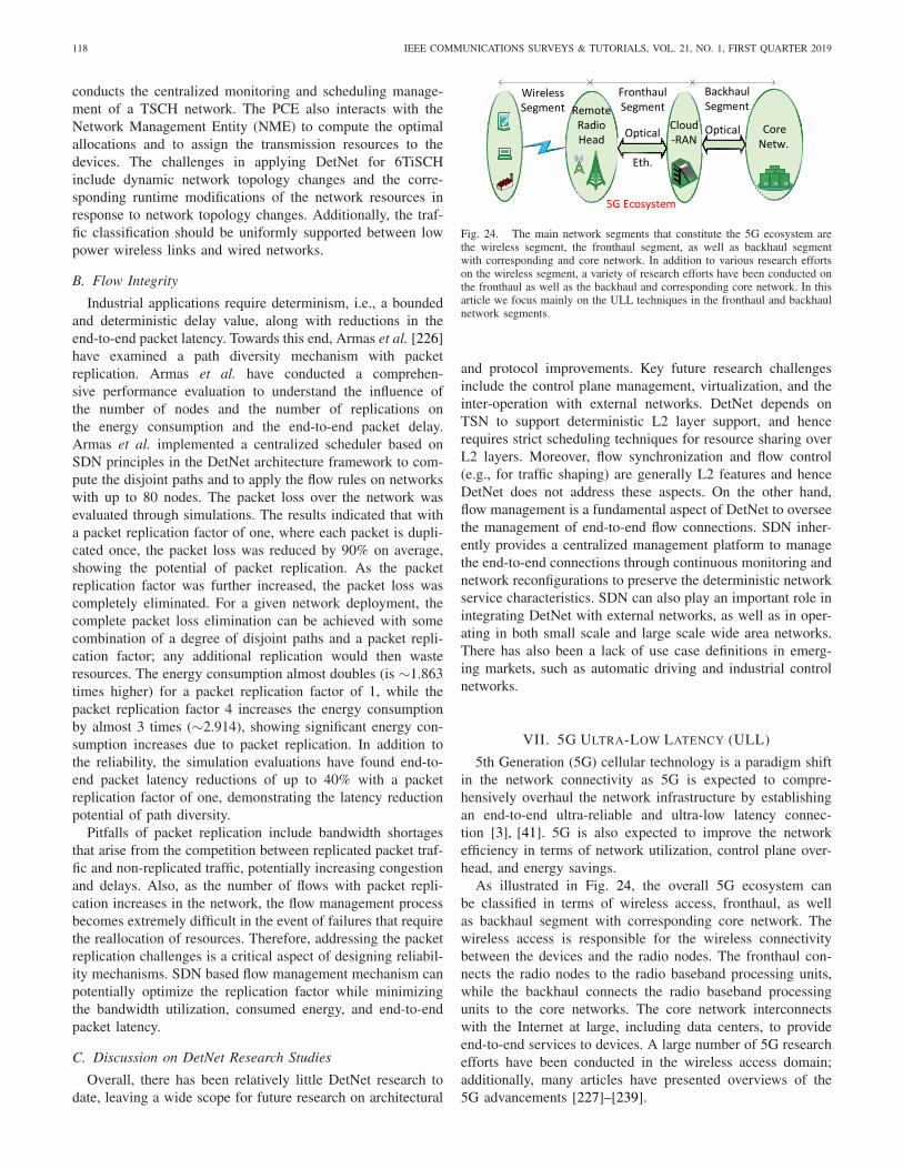
118 IEEE COMMUNICATIONS SURVEYS & TUTORIALS, VOL. 21, NO. 1, FIRST QUARTER 2019
conducts the centralized monitoring and scheduling manage-ment of a TSCH network. The PCE also interacts with theNetwork Management Entity (NME) to compute the optimalallocations and to assign the transmission resources to thedevices. The challenges in applying DetNet for 6TiSCHinclude dynamic network topology changes and the corre-sponding runtime modifications of the network resources inresponse to network topology changes. Additionally, the traf-fic classification should be uniformly supported between lowpower wireless links and wired networks.
B. Flow Integrity
Industrial applications require determinism, i.e., a boundedand deterministic delay value, along with reductions in theend-to-end packet latency. Towards this end, Armas et al. [226]have examined a path diversity mechanism with packetreplication. Armas et al. have conducted a comprehen-sive performance evaluation to understand the influence ofthe number of nodes and the number of replications onthe energy consumption and the end-to-end packet delay.Armas et al. implemented a centralized scheduler based onSDN principles in the DetNet architecture framework to com-pute the disjoint paths and to apply the flow rules on networkswith up to 80 nodes. The packet loss over the network wasevaluated through simulations. The results indicated that witha packet replication factor of one, where each packet is dupli-cated once, the packet loss was reduced by 90% on average,showing the potential of packet replication. As the packetreplication factor was further increased, the packet loss wascompletely eliminated. For a given network deployment, thecomplete packet loss elimination can be achieved with somecombination of a degree of disjoint paths and a packet repli-cation factor; any additional replication would then wasteresources. The energy consumption almost doubles (is ∼1.863times higher) for a packet replication factor of 1, while thepacket replication factor 4 increases the energy consumptionby almost 3 times (∼2.914), showing significant energy con-sumption increases due to packet replication. In addition tothe reliability, the simulation evaluations have found end-to-end packet latency reductions of up to 40% with a packetreplication factor of one, demonstrating the latency reductionpotential of path diversity.
Pitfalls of packet replication include bandwidth shortagesthat arise from the competition between replicated packet traf-fic and non-replicated traffic, potentially increasing congestionand delays. Also, as the number of flows with packet repli-cation increases in the network, the flow management processbecomes extremely difficult in the event of failures that requirethe reallocation of resources. Therefore, addressing the packetreplication challenges is a critical aspect of designing reliabil-ity mechanisms. SDN based flow management mechanism canpotentially optimize the replication factor while minimizingthe bandwidth utilization, consumed energy, and end-to-endpacket latency.
C. Discussion on DetNet Research Studies
Overall, there has been relatively little DetNet research todate, leaving a wide scope for future research on architectural
Fig. 24. The main network segments that constitute the 5G ecosystem arethe wireless segment, the fronthaul segment, as well as backhaul segmentwith corresponding and core network. In addition to various research effortson the wireless segment, a variety of research efforts have been conducted onthe fronthaul as well as the backhaul and corresponding core network. In thisarticle we focus mainly on the ULL techniques in the fronthaul and backhaulnetwork segments.
and protocol improvements. Key future research challengesinclude the control plane management, virtualization, and theinter-operation with external networks. DetNet depends onTSN to support deterministic L2 layer support, and hencerequires strict scheduling techniques for resource sharing overL2 layers. Moreover, flow synchronization and flow control(e.g., for traffic shaping) are generally L2 features and henceDetNet does not address these aspects. On the other hand,flow management is a fundamental aspect of DetNet to overseethe management of end-to-end flow connections. SDN inher-ently provides a centralized management platform to managethe end-to-end connections through continuous monitoring andnetwork reconfigurations to preserve the deterministic networkservice characteristics. SDN can also play an important role inintegrating DetNet with external networks, as well as in oper-ating in both small scale and large scale wide area networks.There has also been a lack of use case definitions in emerg-ing markets, such as automatic driving and industrial controlnetworks.
VII. 5G ULTRA-LOW LATENCY (ULL)
5th Generation (5G) cellular technology is a paradigm shiftin the network connectivity as 5G is expected to compre-hensively overhaul the network infrastructure by establishingan end-to-end ultra-reliable and ultra-low latency connec-tion [3], [41]. 5G is also expected to improve the networkefficiency in terms of network utilization, control plane over-head, and energy savings.
As illustrated in Fig. 24, the overall 5G ecosystem canbe classified in terms of wireless access, fronthaul, as wellas backhaul segment with corresponding core network. Thewireless access is responsible for the wireless connectivitybetween the devices and the radio nodes. The fronthaul con-nects the radio nodes to the radio baseband processing units,while the backhaul connects the radio baseband processingunits to the core networks. The core network interconnectswith the Internet at large, including data centers, to provideend-to-end services to devices. A large number of 5G researchefforts have been conducted in the wireless access domain;additionally, many articles have presented overviews of the5G advancements [227]–[239].
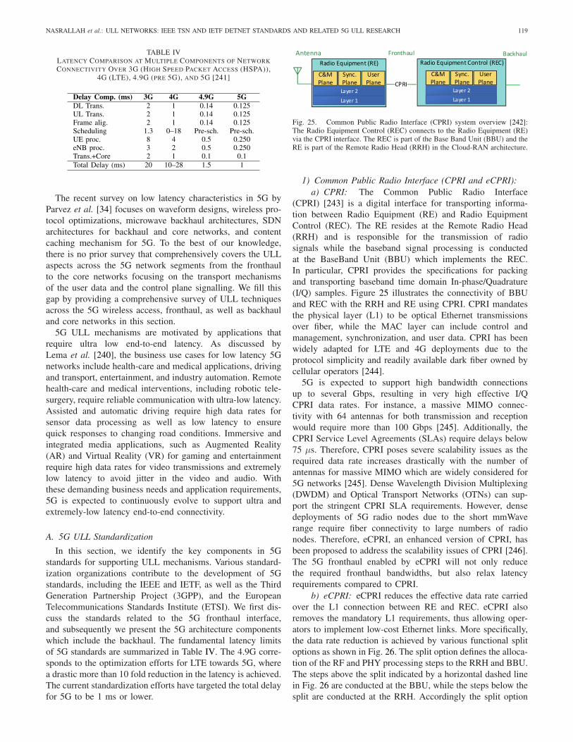
NASRALLAH et al.: ULL NETWORKS: IEEE TSN AND IETF DETNET STANDARDS AND RELATED 5G ULL RESEARCH 119
TABLE IVLATENCY COMPARISON AT MULTIPLE COMPONENTS OF NETWORK
CONNECTIVITY OVER 3G (HIGH SPEED PACKET ACCESS (HSPA)),4G (LTE), 4.9G (PRE 5G), AND 5G [241]
The recent survey on low latency characteristics in 5G byParvez et al. [34] focuses on waveform designs, wireless pro-tocol optimizations, microwave backhaul architectures, SDNarchitectures for backhaul and core networks, and contentcaching mechanism for 5G. To the best of our knowledge,there is no prior survey that comprehensively covers the ULLaspects across the 5G network segments from the fronthaulto the core networks focusing on the transport mechanismsof the user data and the control plane signalling. We fill thisgap by providing a comprehensive survey of ULL techniquesacross the 5G wireless access, fronthaul, as well as backhauland core networks in this section.
5G ULL mechanisms are motivated by applications thatrequire ultra low end-to-end latency. As discussed byLema et al. [240], the business use cases for low latency 5Gnetworks include health-care and medical applications, drivingand transport, entertainment, and industry automation. Remotehealth-care and medical interventions, including robotic tele-surgery, require reliable communication with ultra-low latency.Assisted and automatic driving require high data rates forsensor data processing as well as low latency to ensurequick responses to changing road conditions. Immersive andintegrated media applications, such as Augmented Reality(AR) and Virtual Reality (VR) for gaming and entertainmentrequire high data rates for video transmissions and extremelylow latency to avoid jitter in the video and audio. Withthese demanding business needs and application requirements,5G is expected to continuously evolve to support ultra andextremely-low latency end-to-end connectivity.
A. 5G ULL Standardization
In this section, we identify the key components in 5Gstandards for supporting ULL mechanisms. Various standard-ization organizations contribute to the development of 5Gstandards, including the IEEE and IETF, as well as the ThirdGeneration Partnership Project (3GPP), and the EuropeanTelecommunications Standards Institute (ETSI). We first dis-cuss the standards related to the 5G fronthaul interface,and subsequently we present the 5G architecture componentswhich include the backhaul. The fundamental latency limitsof 5G standards are summarized in Table IV. The 4.9G corre-sponds to the optimization efforts for LTE towards 5G, wherea drastic more than 10 fold reduction in the latency is achieved.The current standardization efforts have targeted the total delayfor 5G to be 1 ms or lower.
Fig. 25. Common Public Radio Interface (CPRI) system overview [242]:The Radio Equipment Control (REC) connects to the Radio Equipment (RE)via the CPRI interface. The REC is part of the Base Band Unit (BBU) and theRE is part of the Remote Radio Head (RRH) in the Cloud-RAN architecture.
1) Common Public Radio Interface (CPRI and eCPRI):a) CPRI: The Common Public Radio Interface
(CPRI) [243] is a digital interface for transporting informa-tion between Radio Equipment (RE) and Radio EquipmentControl (REC). The RE resides at the Remote Radio Head(RRH) and is responsible for the transmission of radiosignals while the baseband signal processing is conductedat the BaseBand Unit (BBU) which implements the REC.In particular, CPRI provides the specifications for packingand transporting baseband time domain In-phase/Quadrature(I/Q) samples. Figure 25 illustrates the connectivity of BBUand REC with the RRH and RE using CPRI. CPRI mandatesthe physical layer (L1) to be optical Ethernet transmissionsover fiber, while the MAC layer can include control andmanagement, synchronization, and user data. CPRI has beenwidely adapted for LTE and 4G deployments due to theprotocol simplicity and readily available dark fiber owned bycellular operators [244].
5G is expected to support high bandwidth connectionsup to several Gbps, resulting in very high effective I/QCPRI data rates. For instance, a massive MIMO connec-tivity with 64 antennas for both transmission and receptionwould require more than 100 Gbps [245]. Additionally, theCPRI Service Level Agreements (SLAs) require delays below75 µs. Therefore, CPRI poses severe scalability issues as therequired data rate increases drastically with the number ofantennas for massive MIMO which are widely considered for5G networks [245]. Dense Wavelength Division Multiplexing(DWDM) and Optical Transport Networks (OTNs) can sup-port the stringent CPRI SLA requirements. However, densedeployments of 5G radio nodes due to the short mmWaverange require fiber connectivity to large numbers of radionodes. Therefore, eCPRI, an enhanced version of CPRI, hasbeen proposed to address the scalability issues of CPRI [246].The 5G fronthaul enabled by eCPRI will not only reducethe required fronthaul bandwidths, but also relax latencyrequirements compared to CPRI.
b) eCPRI: eCPRI reduces the effective data rate carriedover the L1 connection between RE and REC. eCPRI alsoremoves the mandatory L1 requirements, thus allowing oper-ators to implement low-cost Ethernet links. More specifically,the data rate reduction is achieved by various functional splitoptions as shown in Fig. 26. The split option defines the alloca-tion of the RF and PHY processing steps to the RRH and BBU.The steps above the split indicated by a horizontal dashed linein Fig. 26 are conducted at the BBU, while the steps below thesplit are conducted at the RRH. Accordingly the split option
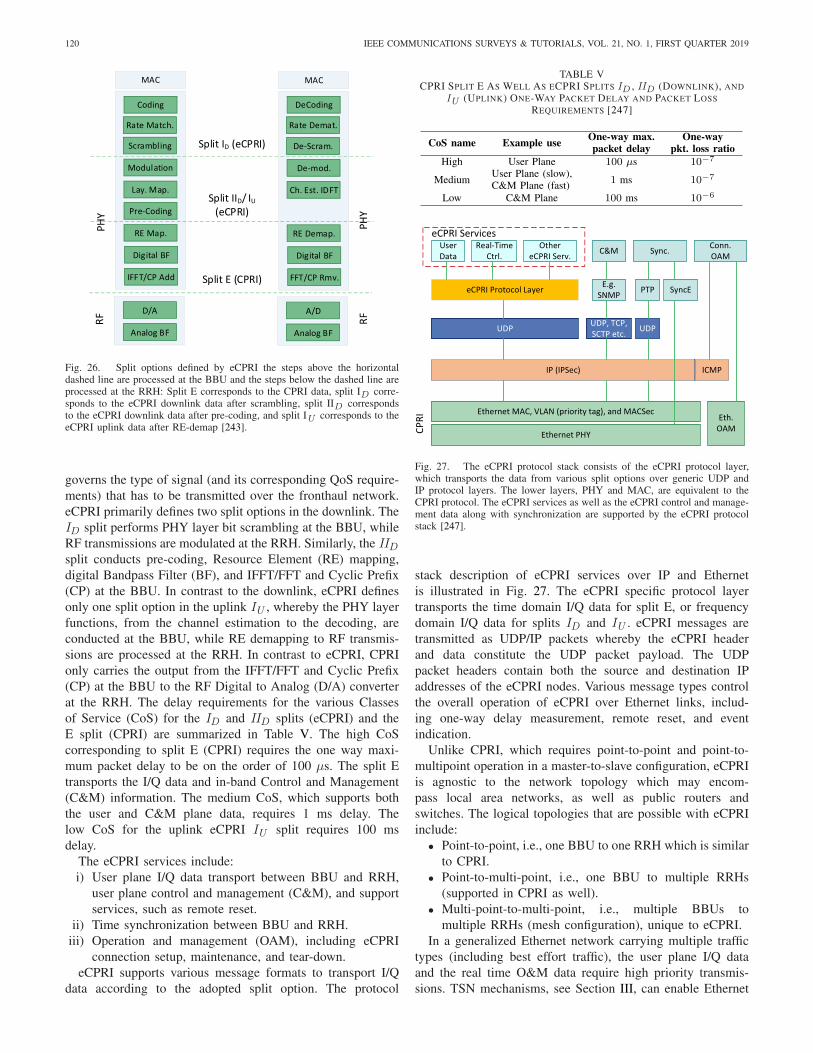
120 IEEE COMMUNICATIONS SURVEYS & TUTORIALS, VOL. 21, NO. 1, FIRST QUARTER 2019
Fig. 26. Split options defined by eCPRI the steps above the horizontaldashed line are processed at the BBU and the steps below the dashed line areprocessed at the RRH: Split E corresponds to the CPRI data, split ID corre-sponds to the eCPRI downlink data after scrambling, split IID correspondsto the eCPRI downlink data after pre-coding, and split IU corresponds to theeCPRI uplink data after RE-demap [243].
governs the type of signal (and its corresponding QoS require-ments) that has to be transmitted over the fronthaul network.eCPRI primarily defines two split options in the downlink. TheID split performs PHY layer bit scrambling at the BBU, whileRF transmissions are modulated at the RRH. Similarly, the IIDsplit conducts pre-coding, Resource Element (RE) mapping,digital Bandpass Filter (BF), and IFFT/FFT and Cyclic Prefix(CP) at the BBU. In contrast to the downlink, eCPRI definesonly one split option in the uplink IU , whereby the PHY layerfunctions, from the channel estimation to the decoding, areconducted at the BBU, while RE demapping to RF transmis-sions are processed at the RRH. In contrast to eCPRI, CPRIonly carries the output from the IFFT/FFT and Cyclic Prefix(CP) at the BBU to the RF Digital to Analog (D/A) converterat the RRH. The delay requirements for the various Classesof Service (CoS) for the ID and IID splits (eCPRI) and theE split (CPRI) are summarized in Table V. The high CoScorresponding to split E (CPRI) requires the one way maxi-mum packet delay to be on the order of 100 µs. The split Etransports the I/Q data and in-band Control and Management(C&M) information. The medium CoS, which supports boththe user and C&M plane data, requires 1 ms delay. Thelow CoS for the uplink eCPRI IU split requires 100 msdelay.
The eCPRI services include:i) User plane I/Q data transport between BBU and RRH,
user plane control and management (C&M), and supportservices, such as remote reset.
ii) Time synchronization between BBU and RRH.iii) Operation and management (OAM), including eCPRI
connection setup, maintenance, and tear-down.eCPRI supports various message formats to transport I/Q
data according to the adopted split option. The protocol
TABLE VCPRI SPLIT E AS WELL AS ECPRI SPLITS ID , IID (DOWNLINK), AND
IU (UPLINK) ONE-WAY PACKET DELAY AND PACKET LOSS
REQUIREMENTS [247]
Fig. 27. The eCPRI protocol stack consists of the eCPRI protocol layer,which transports the data from various split options over generic UDP andIP protocol layers. The lower layers, PHY and MAC, are equivalent to theCPRI protocol. The eCPRI services as well as the eCPRI control and manage-ment data along with synchronization are supported by the eCPRI protocolstack [247].
stack description of eCPRI services over IP and Ethernetis illustrated in Fig. 27. The eCPRI specific protocol layertransports the time domain I/Q data for split E, or frequencydomain I/Q data for splits ID and IU . eCPRI messages aretransmitted as UDP/IP packets whereby the eCPRI headerand data constitute the UDP packet payload. The UDPpacket headers contain both the source and destination IPaddresses of the eCPRI nodes. Various message types controlthe overall operation of eCPRI over Ethernet links, includ-ing one-way delay measurement, remote reset, and eventindication.
Unlike CPRI, which requires point-to-point and point-to-multipoint operation in a master-to-slave configuration, eCPRIis agnostic to the network topology which may encom-pass local area networks, as well as public routers andswitches. The logical topologies that are possible with eCPRIinclude:
• Point-to-point, i.e., one BBU to one RRH which is similarto CPRI.
• Point-to-multi-point, i.e., one BBU to multiple RRHs(supported in CPRI as well).
• Multi-point-to-multi-point, i.e., multiple BBUs tomultiple RRHs (mesh configuration), unique to eCPRI.
In a generalized Ethernet network carrying multiple traffictypes (including best effort traffic), the user plane I/Q dataand the real time O&M data require high priority transmis-sions. TSN mechanisms, see Section III, can enable Ethernet

NASRALLAH et al.: ULL NETWORKS: IEEE TSN AND IETF DETNET STANDARDS AND RELATED 5G ULL RESEARCH 121
Fig. 28. IEEE 802.1 CM defines the support for Ethernet-based fronthaul ina bridged network. Flows are separated into different classes and a specificfronthaul profile is applied to each class to transport the flows over the Ethernetbridges based on the flow requirements [248].
networks to meet the eCPRI delay requirements. eCPRI man-agement messages and user plane data can be regarded asControl Data Traffic (CDT) that is transmitted with high pri-ority scheduling over the TSN network. Traffic requirementsfor user plane data vary for the different split options, whichcan be assigned different TSN priority levels. For instance, theC&M data is typically not as delay sensitive as user plane data;hence, a lower priority can assigned to C&M traffic. However,critical C&M data, such as remote reset while troubleshootinga Remote Equipment (RE) problem, may require higher prior-ity levels than user data. Therefore, two priority levels can beassigned to C&M traffic, i.e., a priority level higher than userdata and another priority level lower than user data. These pri-ority levels can be readily supported by TSN networks, whichaccommodate eight independent priority queues.
c) Summary and lessons learned: 5G technology sup-ports diverse applications with a wide range of data rates andlatency requirements, which directly translate to requirementfor a flexible and scalable fronthaul. CPRI and eCPRI pro-vide standardized protocols for inter-operating with existingcellular infrastructures. CPRI may not be suitable for support-ing massive broadband services due to the very high requiredI/Q data rates. Also, the CPRI latency requirements need tobe carefully considered and may require the judicious use ofthe scheduled traffic concept [168]. eCPRI overcomes the datarate issue through functional splits but increases the complex-ity of remote radio nodes. Another shortcoming of eCPRI isthat the system considers asymmetrical OFDM in the down-link and uplink, i.e., single-carrier OFDM (SC-OFDM) in theuplink. Symmetrical OFDM systems are being investigatedfor increased spectral uplink efficiency [245]. However, thereis no specific split defined for symmetrical OFDM systemsin eCPRI. Remote spectrum analysis for troubleshooting RFissues is possible in CPRI; whereas, eCPRI does not providesuch remote RF evaluation capabilities, although splits IUand ID allow for remote RF management. Hence, mechanismsfor the transmission of sampled time domain I/Q samples fromthe RRH back to the BBU must be developed for advancedtroubleshooting.
2) IEEE 802.1CM: Time-Sensitive Networking forFronthaul: The IEEE 802.1CM standard [248] is a CPRI-IEEE 802.1 collaboration to provide bridged Ethernetconnectivity for fronthaul networks, as illustrated in Fig. 28.An 802.1CM bridge must support a data rate of 1 Gbps
or higher on each port. The IEEE 802.1CM requirementsare derived from CPRI and eCPRI so as to support varioussplits, such as splits at the FFT, demapping, and scramblingradio functions. IEEE 802.1CM defines mechanisms for endstations, bridges, and LANs to establish Ethernet networksthat can support the time sensitive transmissions of fronthaulstreams. In current cellular network deployments, the sep-aration between RRH and BBU requires connectivity withstringent latency and capacity requirements. These fronthaulconnectivity requirements could not be readily provided bytoday’s bridged Ethernet networks.
IEEE 802.1CM provides specific mechanisms, such asscheduling, preemption and synchronization mechanisms, tosatisfy the fronthaul requirements. With IEEE 802.1CM,mobile operators can utilize large segments of existing bridgednetworks to support 5G fronthaul networks, reducing capitalexpenditures. Moreover, centralized management mechanismscan be employed for automatic network reconfigurations,reducing the operational expenditures compared to manualnetwork configuration. IEEE 802.1CM distinguishes Class 1traffic for CPRI and Class 2 traffic for eCPRI. In termsof network synchronization, the IEEE 802.1 CM standardspecifies two mechanisms: i) packet timing using protocols,such as the Precision Time Protocol (PTP) for point-to-point synchronization distribution from a remote commonmaster, and ii) co-located common master for both BBUand RRH.
a) Latency components of a bridge: A bridge supportingfronthaul network functionalities needs to tightly control thelatency and synchronize its functions. The latency for a singlehop in a bridge network is the time duration from the arrivalof the last bit of a given frame at a given bridge port to thearrival of the last bit of the same frame at a particular port atthe next hop bridge. The main delay component are:
i) Store and forward delay tSF due to all the elementsresponsible for the internal frame forwarding from ingressto egress port.
ii) Queueing (interference) delay tQueuing due to ongoingtransmissions of higher priority frames.
iii) Self queuing delay tSelf_Queuing due to frames of thesame class that arrive across multiple ports and need tobe sequentially queued.
iv) Periodic Constant Bit Rate (CBR) high priority data flowdelay tMaxGoldFrameSize+Pre+SFD+IPG. IQ data flowsare referred to as gold flows in IEEE 802.1 CM. The CBRdata delay tMaxGoldFrameSize+Pre+SFD+IPG of a goldframe corresponds to an IQ data frame with maximumframe size with Preamble (Pre), Start Frame Delimiter(SFD), and Inter Packet Gap (IPG).
The total worst-case self-queuing delay in a bridge can beevaluated based on the number Np of ingress ports that canreceive interfering gold frames which need to be transmittedover egress port p, and the total number of flows Fi ,p sup-ported between ingress port i and egress p. Let G i ,p
k denotethe maximum number of frames belonging to a gold flowk traversing from ingress port i to egress port p that canbe grouped into a single time window before the receptionof frames at the ingress edge port of the bridge network.
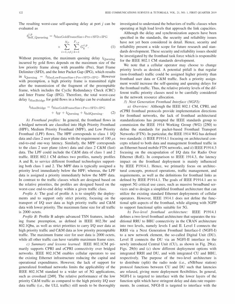
122 IEEE COMMUNICATIONS SURVEYS & TUTORIALS, VOL. 21, NO. 1, FIRST QUARTER 2019
The resulting worst-case self-queuing delay at port j can beevaluated as
tj ,pSelf_Queueing = tMaxGoldFrameSize+Pre+SFD+IPG
×NP∑
i=1,i �=j
Fi,p∑
k=1
G i ,pk . (1)
Without preemption, the maximum queuing delay tQueuingincurred by gold flows depends on the maximum size of thelow priority frame along with preamble (Pre), Start FrameDelimiter (SFD), and the Inter Packet Gap (IPG), which resultsin tQueuing = tMaxLowFrameSize+Pre+SFD+IPG. Howeverwith preemption, a high priority frame is transmitted rightafter the transmission of the fragment of the preemptableframe, which includes the Cyclic Redundancy Check (CRC)and Inter Frame Gap (IFG). Therefore, the total worst-casedelay tMaxBridge for gold flows in a bridge can be evaluated as
tMaxBridge = tMaxGoldFrameSize+Pre+SFD+IPG
+ tSF + tQueuing + tSelfQueuing. (2)
b) Fronthaul profiles: In general, the fronthaul flows ina bridged network are classified into High Priority Fronthaul(HPF), Medium Priority Fronthaul (MPF), and Low PriorityFronthaul (LPF) flows. The HPF corresponds to class 1 I/Qdata and class 2 user plane data with the requirement of 100 µsend-to-end one-way latency. Similarly, the MPF correspondsto the class 2 user plane (slow) data and class 2 C&M (fast)data. The LPF could include the C&M data of class 1 and 2traffic. IEEE 802.1 CM defines two profiles, namely profilesA and B, to service different fronthaul technologies support-ing both class 1 and 2. The MPF data is typically assigned apriority level immediately below the HPF; whereas, the LPFdata is assigned a priority immediately below the MPF data.In contrast to the traffic classes which are designed based onthe relative priorities, the profiles are designed based on theworst-case end-to-end delay within a given traffic class.
Profile A: The goal of profile A is to simplify the deploy-ments and to support only strict priority, focusing on thetransport of I/Q user data as high priority traffic and C&Mdata with lower priority. The maximum fame size for all trafficis 2000 octets.
Profile B: Profile B adopts advanced TSN features, includ-ing frame preemption, as defined in IEEE 802.3br and802.1Qbu, as well as strict priorities to carry I/Q user data ashigh priority traffic and C&M data as low priority preemptabletraffic. The maximum frame size for user data is 2000 octets,while all other traffic can have variable maximum frame sizes.
c) Summary and lessons learned: IEEE 802.1CM pri-marily supports CPRI and eCPRI connectivity over bridgednetworks. IEEE 802.1CM enables cellular operators to usethe existing Ethernet infrastructure reducing the capital andoperational expenditures. However, the lack of support forgeneralized fronthaul networks limits the applicability of theIEEE 802.1CM standard to a wider set of 5G applications,such as crosshaul [249]. The relative performance of the lowpriority C&M traffic as compared to the high priority I/Q userdata traffic (i.e., the ULL traffic) still needs to be thoroughly
investigated to understand the behaviors of traffic classes whenoperating at high load levels that approach the link capacities.
Although the delay and synchronization aspects have beenspecified in the standards, the security and reliability issueshave not yet been considered in detail. Hence, security andreliability present a wide scope for future research and stan-dards development. These security and reliability issues shouldbe investigated by the fronthaul task force which is responsiblefor the IEEE 802.1 CM standards development.
We note that a cellular operator may choose to changepriority levels as desired. A potential pitfall is that regular(non-fronthaul) traffic could be assigned higher priority thanfronthaul user data or C&M traffic. Such a priority assign-ment would increase the self-queuing and queuing delays forthe fronthaul traffic. Thus, the relative priority levels of the dif-ferent traffic priority classes need to be carefully consideredin the network resource allocation.
3) Next Generation Fronthaul Interface (NGFI):a) Overview: Although the IEEE 802.1 CM, CPRI, and
eCPRI fronthaul protocols provide implementation directionsfor fronthaul networks, the lack of fronthaul architecturalstandardizations has prompted the IEEE standards group tocommission the IEEE 1914 Working Group (WG) [250] todefine the standards for packet-based Fronthaul TransportNetworks (FTN). In particular, the IEEE 1914 WG has definedtwo standards: i) IEEE P1914.1 focusing on architectural con-cepts related to both data and management fronthaul traffic inan Ethernet based mobile FTN networks, and ii) IEEE P1914.3focusing on the encapsulation of I/Q data for Radio OverEthernet (RoE). In comparison to IEEE 1914.3, the latencyimpact on the fronthaul deployment is mainly influencedby IEEE P1914.1. Hence, we primarily focus on architec-tural concepts, protocol operations, traffic management, andrequirements, as well as the definitions for fronthaul links asdefined by IEEE P1914.1. The goals of IEEE P1914.1 are tosupport 5G critical use cases, such as massive broadband ser-vices and to design a simplified fronthaul architecture that canutilize the existing standard Ethernet deployments of cellularoperators. However, IEEE 1914.1 does not define the func-tional split aspects of the fronthaul, while aligning with 3GPPto support functional splits suitable for 5G.
b) Two-level fronthaul architecture: IEEE P1914.1defines a two-level fronthaul architecture that separates the tra-ditional RRU to BBU connectivity in the CRAN architectureinto two levels, namely levels I and II. Level I connects theRRH via a Next Generation Fronthaul Interface-I (NGFI-I)to a new network element, the so-called Digital Unit (DU).Level II connects the DU via an NGFI-II interface to thenewly introduced Central Unit (CU), as shown in Fig. 29(a).Figs. 29(b) and (c) show different deployment options withintegrated RRH and DU, and with integrated CU and BBU,respectively. The purpose of the two-level architecture isto distribute (split) the radio node (i.e., eNB/base station)protocol functions between CU and DU such that latenciesare relaxed, giving more deployment flexibilities. In general,NGFI-I is targeted to interface with the lower layers of thefunction split which have stringent delay and data rate require-ments. In contrast, NFGI-II is targeted to interface with the

NASRALLAH et al.: ULL NETWORKS: IEEE TSN AND IETF DETNET STANDARDS AND RELATED 5G ULL RESEARCH 123
Fig. 29. Illustration of two-level architecture options for next-generation fron-thaul transport network: (a) RRH is connected via NGFI-I fronthaul interfaceto Digital Unit (DU) and DU is connected via NGFI-II interface to CentralUnit, (b) RRH is connected via NGFI-I interface to integrated CU and DU,and (c) DU is integrated with RRH and connected via NGFI-II to CU [250].
TABLE VINGFI TRANSPORT CLASSES OF SERVICE; LOW SPLIT, MED. SPLIT,
AND HIGH SPLIT ARE RELATIVE TO THE POSITIONING OF THE
SPLIT IN FIG. 26, WHEREBY THE LOW SPLIT IS CLOSER
TO THE BOTTOM OF FIG. 26
higher layers of the function split relative to NGFI-I, relaxingthe requirements for the fronthaul link.
The NGFI is designed to mainly address:i) Scalability: To enable C-RANs and Virtual-RANs that are
functional split and traffic independent.ii) Resource Utilization: To achieve statistical multiplexing
by supporting variable MIMO and CoordinatedMultipoint (CoMP) for 5G.
iii) Flexibility: To operate in a radio technology agnos-tic manner while supporting SDN controlled dynamicreconfigurations.
iv) Cost Effective: To utilize existing cellular network infras-tructure.
Additionally, NGFI supports connectivity to HeterogeneousNetworks (HetNets) by decoupling the transport requirementsfrom the radio technologies. Thus, multiple traffic classes, assummarized in Table VI, can be transported by the NGFInetwork, mainly to support latencies according to the applica-tion demands. The C&M class supports low-latency controlplane data for radio node signalling. Data plane latenciesvary according to the different subclasses 0–4 to supportmultiple technologies and deployment versions with multiplesplit options. Subclass 0 requires the highest priority with50 µs of maximum allowed latency, while subclass 4 has the
lowest priority and a 10 ms maximum delay bound. Subclass4 can, for instance, be used for the legacy backhaul overthe NGFI interface. The traffic of each subclass is indepen-dently transported between the end points without any mutualinterference while achieving statical multiplexing gains amongthe subclasses.
c) Summary and lessons learned: The NGFI primar-ily addresses the scalability and cost issues with the currentfronthaul solutions, such as CPRI. With NGFI, connectionsbetween DU and CU can be directly connected by an Ethernetlink supporting IEEE P1914.1 specifications. The NFGI L2subclass 0 transport service can readily accommodate therequirements of the existing CPRI deployments without anychanges to the infrastructure deployments. Thus, NGFI isexpected to play a significant role in the unification of hetero-geneous radio technologies at the transport level and supportconverged fronthaul and backhaul networks for converged andcoexisting 4G and 5G technologies. An important aspect toinvestigate in future research is the tradeoff between linkutilization and multiplexing gain for the standard Ethernetnetworks while adopting these new fronthaul support archi-tectures and protocols.
4) Backhaul Networks:a) Overview: The backhaul networks consisting of core
network elements play a critical role in setting up the end-to-end flows. Core networks control the user data schedulingin both uplink and downlink. The control signalling of theradio technology, e.g., LTE, can contribute to flow latencywhen user devices transition among various states, e.g., idleto active (connected) and vice versa [251]–[253]. For scenar-ios with intermittent data activity, devices typically implementa state transitioning mechanism from active to idle to con-serve computing and wireless resources. For instance, if theinter packet delay is more than 40 ms, the device can pro-actively change the radio control state to idle. Thus, withina single ULL flow session, there can be multiple user devicestate transitions between idle and active. The core networkmanages the control plane signalling of the radio technologywhereby advanced methods can be implemented to reduce thestate transition overhead during flow setup, thereby reducingthe latency. For ULL flows, irrespective of whether the traf-fic is intermittent or has a constant bit rate, the end-to-endlatency should be minimized for both flow setup and steadystate traffic flow.
An efficient backhaul network design can reduce controlplane signalling for both initial ULL flow setup and steadystate traffic. We give brief overviews of the two standardiza-tion efforts that efficiently implement the 5G core networkfunctions for setting up and supporting ULL flows, namelyControl and User Plane Separation (CUPS) of EPC and NextGeneration (NG) Core.
b) Control and user plane separation (CUPS) of EPC:The SDN paradigm of separating the control and data planefunctions while centralizing the overall control plane hasprovided substantial advantages in traditional networks. The3GPP has proposed Control and User Plane Separation(CUPS) [254] for the Evolved Packet Core (EPC) backhaul ofthe LTE radio technology, see Fig. 30, to adapt SDN principles
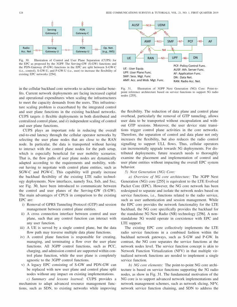
124 IEEE COMMUNICATIONS SURVEYS & TUTORIALS, VOL. 21, NO. 1, FIRST QUARTER 2019
Fig. 30. Illustration of Control and User Plane Separation (CUPS) forthe EPC as proposed by the 3GPP. The Serving-GW (S-GW) functions andthe PDN-Gateway (P-GW) functions in the EPC are split between S-GW-C(i.e., control), S-GW-U, and P-GW-U (i.e., user) to increase the flexibility ofexisting EPC networks [254].
in the cellular backhaul core networks to achieve similar bene-fits. Current network deployments are facing increased capitaland operational expenditures when scaling the infrastructuresto meet the capacity demands from the users. This infrastruc-ture scaling problem is exacerbated by the integrated controland user plane functions in the existing backhaul networks.CUPS targets i) flexible deployments in both distributed andcentralized control plane, and ii) independent scaling of controland user plane functions.
CUPS plays an important role in reducing the overallend-to-end latency through the cellular operator networks byselecting the user plane nodes that are close to the RANnode. In particular, the data is transported without havingto interact with the control plane nodes for the path setup,which is especially beneficial for user mobility scenarios.That is, the flow paths of user plane nodes are dynamicallyadapted according to the requirements and mobility, with-out having to negotiate with control plane entities, such asSGW-C and PGW-C. This capability will greatly increasethe backhaul flexibility of the existing LTE radio technol-ogy deployments. New interfaces, namely Sxa, Sxb, and Sxc,see Fig. 30, have been introduced to communicate betweenthe control and user planes of the Serving-GW (S-GW).The main advantages of CPUS in comparison to the existingEPC are:
i) Removal of GPRS Tunneling Protocol (GTP) and sessionmanagement between control plane entities.
ii) A cross connection interface between control and userplane, such that any control function can interact withany user function.
iii) A UE is served by a single control plane, but the dataflow path may traverse multiple data plane functions.
iv) A control plane function is responsible for creating,managing, and terminating a flow over the user planefunctions. All 3GPP control functions, such as PCC,charging, and admission control are supported within con-trol plane function, while the user plane is completelyagnostic to the 3GPP control functions.
v) A legacy EPC consisting of S-GW and PDN-GW canbe replaced with new user plane and control plane splitnodes without any impact on existing implementations.c) Summary and lessons learned: CUPS provides a
mechanism to adapt advanced resource management func-tions, such as SDN, to existing networks while improving
Fig. 31. Illustration of 3GPP Next Generation (NG) Core: Point-to-point reference architecture based on service functions to support 5G radionodes [255].
the flexibility. The reduction of data plane and control planeoverhead, particularly the removal of GTP tunneling, allowsuser data to be transported without encapsulation and with-out GTP sessions. Moreover, the user device state transi-tions trigger control plane activities in the core networks.Therefore, the separation of control and data plane not onlyincreases the flexibility, but also reduces the radio controlsignalling to support ULL flows. Thus, cellular operatorscan incrementally upgrade towards 5G deployments. For dis-tributed deployments, future research needs to thoroughlyexamine the placement and implementation of control anduser plane entities without impacting the overall EPC systembehavior.
5) Next Generation (NG) Core:a) Overview of NG core architecture: The 3GPP Next
Generation (NG) core [255] is equivalent to the LTE EvolvedPacket Core (EPC). However, the NG core network has beenredesigned to separate and isolate the network nodes based onservice functions, i.e., functions related to the radio service,such as user authentication and session management. Whilethe EPC core provides the network functionality for the LTEbackhaul, the NG core specifically provides the backhaul forthe standalone 5G New Radio (NR) technology [256]. A non-standalone 5G would operate in coexistence with EPC andLTE support.
The existing EPC core collectively implements the LTEradio service functions in a combined fashion within thebackhaul network gateways, such as S-GW and P-GW. Incontrast, the NG core separates the service functions at thenetwork nodes level. The service function concept is akin toNetwork Function Virtualization (NFV) in that multiple vir-tualized network functions are needed to implement a singleservice function.
b) NG core elements: The point-to-point NG core archi-tecture is based on service functions supporting the 5G radionodes, as show in Fig. 31. The fundamental motivation of theNG core is to support advanced network implementations andnetwork management schemes, such as network slicing, NFV,network service function chaining, and SDN to address the

NASRALLAH et al.: ULL NETWORKS: IEEE TSN AND IETF DETNET STANDARDS AND RELATED 5G ULL RESEARCH 125
scalability and flexibility of the core network. Each NG coreelement is connected to other elements through Nx interfaces.Critical NG core elements include:
i) The Access and Mobility Function (AMF) implementsthe access control and mobility aspects of the usercontext.
ii) The Session Management Function (SMF) is responsiblefor the data path setup and tracking and terminating basedon the policy function.
iii) The User Plane Function (UPF) defines the data pathcharacteristics based on the users requirements and pol-icy.
iv) The Policy Control Function (PCF) controls the user pol-icy, such as roaming and network resource allocations, fornetwork management, including network slicing.
v) The Unified Data Management (UDM) manages the sub-scriber information which is used for admission controland for defining the data path policies.
vi) The Network Repository Function (NRF) maintains theregistry of service functions distributed throughout thenetwork.c) Summary and lessons learnt: The NG core decouples
the network service functions from the gateway nodes, allow-ing the core network to implement the network nodes basedon service functions, which enhances the deployment flexibil-ity. As a result, operators have more freedom in transitioningfrom an existing core network to the NG core by separat-ing the core network elements based on the service functions.However, future research needs to thoroughly examine theoverhead of the control plane management, e.g., virtualiza-tion [257]. For instance, the overhead directly influences powerconsumption, and network efficiency for the ULL flow setup inthe core network data path, which must be carefully evaluated.Therefore, performance, resource utilization, and overheadmust be considered while designing the optimal infrastructuredeployment.
6) Discussion on 5G ULL Standardization: In this sectionwe have provided a brief overview of key components in the5G standardization efforts that contribute to ULL connectiv-ity. Several wireless connectivity and signalling optimizationshave reduced the latency overhead in the data and controlplanes of the wireless air interface. Also, the new RadioResource Control (RRC) inactive state reduces the signallingfor the RRC inactive to active state transition (compared tothe conventional LTE RRC idle to RRC active transition). Awide variety of options, e.g., functional splits of CPRI andNGFI for the fronthaul, exist for meeting the requirements of5G components. Therefore, the design of an end-to-end 5Gsupported system requires a comprehensive latency analysisacross all segments to select the right candidate set of transportmechanisms, protocols, and architectural solutions.
Broadly speaking, the improvements that the TSN standardsbring to bridged networks can feed into novel standard devel-opments for Ultra-Reliable and Low Latency Communications(URLLC) in cellular networks in two main areas: i) back-haul network, and ii) fronthaul network. In traditional cellularnetworks, the various backhaul network nodes, such as theHome Subscriber Service (HSS) and the Radio Network
Controller (RNC), are typically interconnected by bridgednetworks. The adoption of TSN improves the capabilitiesand enhances the performance of the bridged networks thatinterconnect the backhaul nodes. In contrast, fronthaul nodes,such as the Remote Radio Head (RRH) and the Cloud-RAN (C-RAN), were typically interconnected by point-to-point optical links (as opposed to the bridged networks) asthe fronthaul interconnections have very strict latency andthroughput requirements. The introduction of TSN enablesbridged networks to provide the strict latency and throughputrequirements needed for the fronthaul. Thus, TSN can enablethe end-to-end URLLC support across both the fronthaul andthe backhaul for cellular networks.
Overall, the adaptability of each solution for 5G deploymentcould impact the end-to-end ULL flow latency. Flexibilitycould improve the scalability and network utilization, but thecontrol plane separation requires careful consideration of con-trol plane overhead and latency. Similarly, deployments of newarchitectures, such as NG core, could result in efficient back-haul management to support ULL mechanism with minimaloverhead, but may require high expenditures for cellular oper-ators. Nevertheless, as deployment options vary widely basedon the implementation, relative performance evaluations basedon distances between different nodes, interfaces, protocol over-head, transport mechanisms, and architectural considerationsneed to be conducted in future research as ground worktowards optimal 5G system design.
B. 5G ULL Research Studies
This section surveys the research studies on 5G ULL mech-anisms following the classification in Fig. 32. In particular, wefirst give a brief overview of the main ULL research directionsin the 5G wireless access segment and refer to the exten-sive 5G wireless access literature for more details [34], [35],[229], [258]–[260]. Then we survey in detail the research stud-ies addressing ULL in the fronthaul, backhaul, and networkmanagement of fronthaul and backhaul.
1) 5G Wireless Access ULL Research Studies: In this sec-tion we give a brief overview of the main research directionson ULL techniques in the 5G wireless access segment. Effortsto reduce the latency in the wireless access segment havebeen mainly focused on two aspects: i) shortening of theTransmission Time Interval (TTI), and ii) reduced process-ing time for each TTI [272]. The TTI is the fundamental timeunit for the protocol operations, e.g., transmissions, in a givenwireless technology, e.g., LTE. A shorter TII contributes toan overall reduced Round-Trip Time (RTT) due to shortercycles. For example, in LTE, the number of OFDM symbolsin one TTI can be reduced from 7 to 2 or 3 OFDM symbol toreduce the latency [273]. In contrast to LTE which uses onlyOrthogonal Frequency Division Multiplexing (OFDM) basedwaveforms, the New Radio (NR) access technology [274] for5G provides a platform to design and implement more flexi-ble waveforms based on both OFDM and non-OFDM over awide range of spectrum resources, including microwave andmmWave [275].
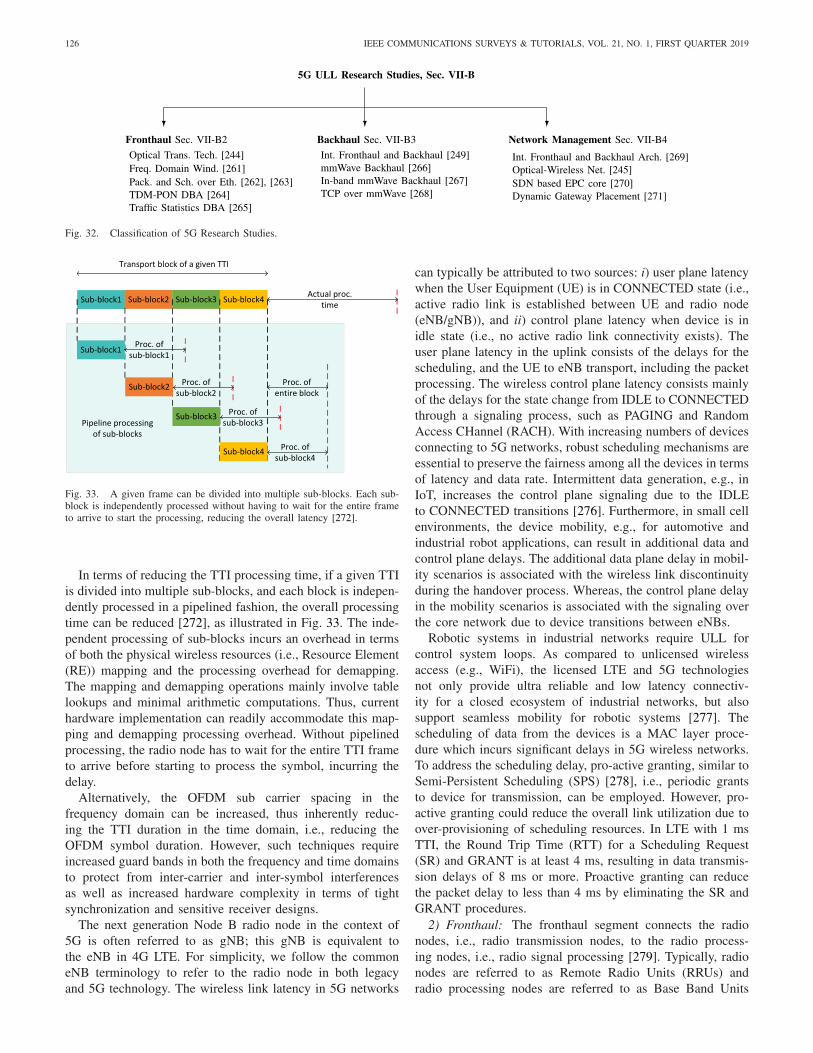
126 IEEE COMMUNICATIONS SURVEYS & TUTORIALS, VOL. 21, NO. 1, FIRST QUARTER 2019
Fig. 32. Classification of 5G Research Studies.
Fig. 33. A given frame can be divided into multiple sub-blocks. Each sub-block is independently processed without having to wait for the entire frameto arrive to start the processing, reducing the overall latency [272].
In terms of reducing the TTI processing time, if a given TTIis divided into multiple sub-blocks, and each block is indepen-dently processed in a pipelined fashion, the overall processingtime can be reduced [272], as illustrated in Fig. 33. The inde-pendent processing of sub-blocks incurs an overhead in termsof both the physical wireless resources (i.e., Resource Element(RE)) mapping and the processing overhead for demapping.The mapping and demapping operations mainly involve tablelookups and minimal arithmetic computations. Thus, currenthardware implementation can readily accommodate this map-ping and demapping processing overhead. Without pipelinedprocessing, the radio node has to wait for the entire TTI frameto arrive before starting to process the symbol, incurring thedelay.
Alternatively, the OFDM sub carrier spacing in thefrequency domain can be increased, thus inherently reduc-ing the TTI duration in the time domain, i.e., reducing theOFDM symbol duration. However, such techniques requireincreased guard bands in both the frequency and time domainsto protect from inter-carrier and inter-symbol interferencesas well as increased hardware complexity in terms of tightsynchronization and sensitive receiver designs.
The next generation Node B radio node in the context of5G is often referred to as gNB; this gNB is equivalent tothe eNB in 4G LTE. For simplicity, we follow the commoneNB terminology to refer to the radio node in both legacyand 5G technology. The wireless link latency in 5G networks
can typically be attributed to two sources: i) user plane latencywhen the User Equipment (UE) is in CONNECTED state (i.e.,active radio link is established between UE and radio node(eNB/gNB)), and ii) control plane latency when device is inidle state (i.e., no active radio link connectivity exists). Theuser plane latency in the uplink consists of the delays for thescheduling, and the UE to eNB transport, including the packetprocessing. The wireless control plane latency consists mainlyof the delays for the state change from IDLE to CONNECTEDthrough a signaling process, such as PAGING and RandomAccess CHannel (RACH). With increasing numbers of devicesconnecting to 5G networks, robust scheduling mechanisms areessential to preserve the fairness among all the devices in termsof latency and data rate. Intermittent data generation, e.g., inIoT, increases the control plane signaling due to the IDLEto CONNECTED transitions [276]. Furthermore, in small cellenvironments, the device mobility, e.g., for automotive andindustrial robot applications, can result in additional data andcontrol plane delays. The additional data plane delay in mobil-ity scenarios is associated with the wireless link discontinuityduring the handover process. Whereas, the control plane delayin the mobility scenarios is associated with the signaling overthe core network due to device transitions between eNBs.
Robotic systems in industrial networks require ULL forcontrol system loops. As compared to unlicensed wirelessaccess (e.g., WiFi), the licensed LTE and 5G technologiesnot only provide ultra reliable and low latency connectiv-ity for a closed ecosystem of industrial networks, but alsosupport seamless mobility for robotic systems [277]. Thescheduling of data from the devices is a MAC layer proce-dure which incurs significant delays in 5G wireless networks.To address the scheduling delay, pro-active granting, similar toSemi-Persistent Scheduling (SPS) [278], i.e., periodic grantsto device for transmission, can be employed. However, pro-active granting could reduce the overall link utilization due toover-provisioning of scheduling resources. In LTE with 1 msTTI, the Round Trip Time (RTT) for a Scheduling Request(SR) and GRANT is at least 4 ms, resulting in data transmis-sion delays of 8 ms or more. Proactive granting can reducethe packet delay to less than 4 ms by eliminating the SR andGRANT procedures.
2) Fronthaul: The fronthaul segment connects the radionodes, i.e., radio transmission nodes, to the radio process-ing nodes, i.e., radio signal processing [279]. Typically, radionodes are referred to as Remote Radio Units (RRUs) andradio processing nodes are referred to as Base Band Units

NASRALLAH et al.: ULL NETWORKS: IEEE TSN AND IETF DETNET STANDARDS AND RELATED 5G ULL RESEARCH 127
(BBUs). Cloud-RAN (CRAN) technology [280] centralizesand virtualizes the BBU functions such that a given BBUcan connect to and serve several RRHs. Initial CRAN designsentirely virtualized the BBU functions and transported onlytime domain In-Phase/Quadrature (I/Q) samples to RRHs.However, the time domain I/Q transport technology was lim-ited by strict delay and bandwidth requirements that hamperedthe scalability of deployments. Recent CRAN designs fea-ture flexible BBU function separation between CRAN andRRU to meet scalability and latency demands [281], [282].While there exist extensive discussions on fronthaul chal-lenges and future designs [283]–[286], we focus onthe key aspects of fronthaul techniques supporting ULLconnectivity.
a) Optical transport techniques: The Common PublicRadio Interface (CPRI) [243], see Section VII-A1, imposesan overall fronthaul link delay limit of 5 ms, excluding thepropagation delay [243]. Typically, the distance between BBUand RRU is 20 km with a delay tolerance of 100 µs and afrequency accuracy within 2 ppm (parts per billion). In addi-tion to the CPRI requirements, the deployment considerationshould also consider the availability of fiber, cost efficiency,CPRI propagation delay, as well as administration and man-agement, since fiber providers are typically different frommobile network providers. The main topology considerationfor deployments are the point-to-point, daisy chain, multi-path ring, and mesh topologies. Point-to-point links providededicated fiber resources for the fronthaul connectivity, butcan be expensive. The daisy chain topology allows the fiberresources to be shared among multiple RRUs; however, a linkfailure can impact all the connected RRUs. Multipath ring andmesh topologies provide generally a better balance betweenfiber availability, cost, and resilience to link failures. Fronthauldata can be transported through several optical transporttechniques [244]:
Optical Transport Network (OTN): The OTN uses a TDMapproach over a single wavelength which can be extendedto multiple wavelengths through dense wavelength divisionmultiplexing (DWDM). OTN has relatively high power con-sumption, as OTN equipment requires power for the opticaltransmissions at both receiver and transmitter.
Passive Optical Network (PON): PONs may provide a cost-effective option for fiber deployments, if PONs are alreadydeployed for fiber to the home connections. Recent PONdevelopments [287]–[292] support both high bit rates and lowlatencies to meet the fronthaul requirements. PON technologyis also power efficient as compared to the OTN.
Point-to-Point With CWDM: Point-to-point links with awavelength multiplexer for Coarse Wavelength DivisionMultiplexing (CWDM) are generally cheaper than an OTNwith DWDM. Motivated by diverse optical transport options,Chanclou et al. [244] have proposed a WDM optical networksolution to meet the data rates and latency requirements ofthe CRAN fronthaul. Automatic wavelength assignment isenabled by passively monitoring the RRUs through a self-seeded approach [293] that considers the bit rates, latencies,jitter and synchronization, as well as fiber availability of theCPRI links.
b) Frequency domain windowing: The general 5G end-to-end latency guideline is 1 ms, while the total fronthaullink (propagation) delay budget is 200 µs [294]. Consider a20 km fronthaul link, then the processing delay (for CPRIsignal and protocol processing) would need to be signifi-cantly lower than the link (propagation) delay, i.e., on theorder of a few µs. The general consideration for the pro-cessing delay in the fronthaul is 5 µs. In an effort to furtherreduce the processing delay of 5 µs, Liu et al. [261] havedesigned an optical transport system supporting the CPRI-equivalent rate of 59 Gbps. 48 LTE RF signals of 20 MHzeach were transmitted through a single WDM channel withan effective RF bandwidth of 1.5 GHz. The processing delaywas reduced through a Frequency Domain Windowing (FDW)technique that reduces the overall FFT/IFFT size in the processof channel aggregation and de-aggregation. FDW is applied toeach N-point IFFT corresponding to every aggregated channel.The FDW technique attenuates the high-frequency componentssuch that the inter-channel crosstalk is reduced. As a result,the effective FFT/IFFT size can be reduced, thereby reduc-ing the overall processing latency. The experimental results forthe fronthaul distance of 5 km have shown an overall fronthauldelay reduction from 5 µs to 2 µs.
c) Packetization and scheduling over Ethernet: Similarto optical transport of I/Q data from BBU to RRH, I/Q datacan be digitized and packetized for the transmissions overEthernet. Radio over Ethernet (RoE) [295]–[298] defines theprocess of converting radio signal I/Q data to packets whichcan be transported over Ethernet. The main issues associatedwith the packetization process while encapsulating the I/Qdata over the fronthaul link are: i) overhead, ii) packetizationlatency, and iii) scheduling delay. The packetization overheadresults from the frame and packet headers. Therefore, to reducethe overhead, each frame must be created with the maximumI/Q data possible such that the overall number of packets andEthernet frames is minimized. However, a large frame sizeadds wait time for the data filling up the maximum framesize. Hence, reducing the latency requires the transmission ofshort frames.
The scheduling of Ethernet frames can provide multiplexinggain through resource sharing, however, the scheduling canincur queuing delays. Therefore, to achieve low latency theoverhead, packetization latency, and scheduling delay must becarefully considered. Chang et al. [262] have evaluated theCRAN performance in terms of packetization and schedulingon the Ethernet fronthaul. For functional splits along layerboundaries, for instance when the complete PHY layer isimplemented in the RRH, or the complete MAC and PHYlayers are implemented in the RRH, an RRH Ethernet gate-way has been introduced to perform the scheduling, aggregatethe traffic from RRH nodes, and discard the packets which arepast their deadlines. For instance, look-ahead depth packetiza-tion packs channel estimation I/Q data such that the channelestimation data precedes regular payload data in the demodu-lation. That is, demodulation does not wait for all the frameI/Q data to process the I/Q data related to channel estimation.
In contrast, the prefetch method [262] waits uniformly overall the I/Q data for the packetization to receive the Reference
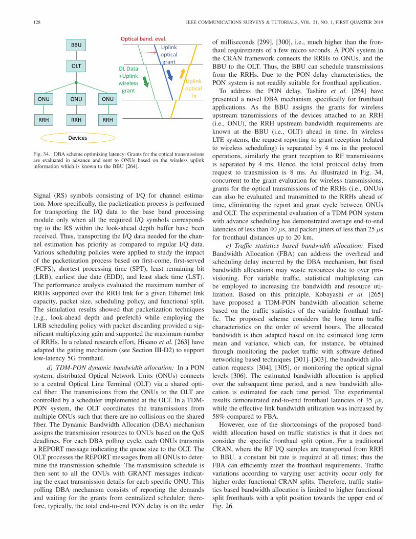
128 IEEE COMMUNICATIONS SURVEYS & TUTORIALS, VOL. 21, NO. 1, FIRST QUARTER 2019
Fig. 34. DBA scheme optimizing latency: Grants for the optical transmissionsare evaluated in advance and sent to ONUs based on the wireless uplinkinformation which is known to the BBU [264].
Signal (RS) symbols consisting of I/Q for channel estima-tion. More specifically, the packetization process is performedfor transporting the I/Q data to the base band processingmodule only when all the required I/Q symbols correspond-ing to the RS within the look-ahead depth buffer have beenreceived. Thus, transporting the I/Q data needed for the chan-nel estimation has priority as compared to regular I/Q data.Various scheduling policies were applied to study the impactof the packetization process based on first-come, first-served(FCFS), shortest processing time (SPT), least remaining bit(LRB), earliest due date (EDD), and least slack time (LST).The performance analysis evaluated the maximum number ofRRHs supported over the RRH link for a given Ethernet linkcapacity, packet size, scheduling policy, and functional split.The simulation results showed that packetization techniques(e.g., look-ahead depth and prefetch) while employing theLRB scheduling policy with packet discarding provided a sig-nificant multiplexing gain and supported the maximum numberof RRHs. In a related research effort, Hisano et al. [263] haveadapted the gating mechanism (see Section III-D2) to supportlow-latency 5G fronthaul.
d) TDM-PON dynamic bandwidth allocation: In a PONsystem, distributed Optical Network Units (ONUs) connectsto a central Optical Line Terminal (OLT) via a shared opti-cal fiber. The transmissions from the ONUs to the OLT arecontrolled by a scheduler implemented at the OLT. In a TDM-PON system, the OLT coordinates the transmissions frommultiple ONUs such that there are no collisions on the sharedfiber. The Dynamic Bandwidth Allocation (DBA) mechanismassigns the transmission resources to ONUs based on the QoSdeadlines. For each DBA polling cycle, each ONUs transmitsa REPORT message indicating the queue size to the OLT. TheOLT processes the REPORT messages from all ONUs to deter-mine the transmission schedule. The transmission schedule isthen sent to all the ONUs with GRANT messages indicat-ing the exact transmission details for each specific ONU. Thispolling DBA mechanism consists of reporting the demandsand waiting for the grants from centralized scheduler; there-fore, typically, the total end-to-end PON delay is on the order
of milliseconds [299], [300], i.e., much higher than the fron-thaul requirements of a few micro seconds. A PON system inthe CRAN framework connects the RRHs to ONUs, and theBBU to the OLT. Thus, the BBU can schedule transmissionsfrom the RRHs. Due to the PON delay characteristics, thePON system is not readily suitable for fronthaul application.
To address the PON delay, Tashiro et al. [264] havepresented a novel DBA mechanism specifically for fronthaulapplications. As the BBU assigns the grants for wirelessupstream transmissions of the devices attached to an RRH(i.e., ONU), the RRH upstream bandwidth requirements areknown at the BBU (i.e., OLT) ahead in time. In wirelessLTE systems, the request reporting to grant reception (relatedto wireless scheduling) is separated by 4 ms in the protocoloperations, similarly the grant reception to RF transmissionsis separated by 4 ms. Hence, the total protocol delay fromrequest to transmission is 8 ms. As illustrated in Fig. 34,concurrent to the grant evaluation for wireless transmissions,grants for the optical transmissions of the RRHs (i.e., ONUs)can also be evaluated and transmitted to the RRHs ahead oftime, eliminating the report and grant cycle between ONUsand OLT. The experimental evaluation of a TDM PON systemwith advance scheduling has demonstrated average end-to-endlatencies of less than 40 µs, and packet jitters of less than 25 µsfor fronthaul distances up to 20 km.
e) Traffic statistics based bandwidth allocation: FixedBandwidth Allocation (FBA) can address the overhead andscheduling delay incurred by the DBA mechanism, but fixedbandwidth allocations may waste resources due to over pro-visioning. For variable traffic, statistical multiplexing canbe employed to increasing the bandwidth and resource uti-lization. Based on this principle, Kobayashi et al. [265]have proposed a TDM-PON bandwidth allocation schemebased on the traffic statistics of the variable fronthaul traf-fic. The proposed scheme considers the long term trafficcharacteristics on the order of several hours. The allocatedbandwidth is then adapted based on the estimated long termmean and variance, which can, for instance, be obtainedthrough monitoring the packet traffic with software definednetworking based techniques [301]–[303], the bandwidth allo-cation requests [304], [305], or monitoring the optical signallevels [306]. The estimated bandwidth allocation is appliedover the subsequent time period, and a new bandwidth allo-cation is estimated for each time period. The experimentalresults demonstrated end-to-end fronthaul latencies of 35 µs,while the effective link bandwidth utilization was increased by58% compared to FBA.
However, one of the shortcomings of the proposed band-width allocation based on traffic statistics is that it does notconsider the specific fronthaul split option. For a traditionalCRAN, where the RF I/Q samples are transported from RRHto BBU, a constant bit rate is required at all times; thus theFBA can efficiently meet the fronthaul requirements. Trafficvariations according to varying user activity occur only forhigher order functional CRAN splits. Therefore, traffic statis-tics based bandwidth allocation is limited to higher functionalsplit fronthauls with a split position towards the upper end ofFig. 26.

NASRALLAH et al.: ULL NETWORKS: IEEE TSN AND IETF DETNET STANDARDS AND RELATED 5G ULL RESEARCH 129
f) Summary and lessons learnt: In a typical CRANdeployment where the RF I/Q is transported from RRH toBBU, the fronthaul traffic is independent of the user datawhich results in a constant bit rate over fronthaul linksat all times to support the normal operations of BBU andRRH. Hence, there can be significant power consumptionoverhead for the CRAN deployment [307], [308]. Therefore,the new designs of fronthaul solutions should consider theoverall energy consumption in addition to the end-to-endlatency [309]. Several advanced physical layer techniques,such as, modulation, detection, and DSP (e.g., I/Q compres-sion) for fiber transmissions have been proposed as part ofenergy efficient designs [310]–[312]. While the higher orderfunctional splits provide statistical multiplexing gains, theworst-case delay must be analyzed to ensure that latencyis within the delay budget of the fronthaul link. The fron-thaul infrastructure is typically non-flexible and must supportthe deployments of future 5G networks [313]. Therefore, thefronthaul designs, such as bandwidth allocation and resourcesharing mechanism designs, should be able to readily accom-modate new developments in the 5G technology. Althoughseveral techniques exists to mitigate the delay in fronthaulnetworks, there has been no research yet to address the syn-chronization of RRH and BBU to a universal timing. Flexiblefronthaul techniques can be developed based on reconfig-urable network functions and physical layer entities, such asmodulators and transparent spectral converters, in the frame-work of Software Defined Optical Networks (SDON) [314].For instance, Cvijetic et al. [315] have proposed an SDNbased topology-reconfigurable optical fronthaul architecture.The dynamic reconfiguration of fronthaul can support lowlatency inter BS communications necessary for bidirectionalCoordinated MultiPoint (CoMP) for inter-cell interferencecancellation and inter-cell D2D.
3) Backhaul:a) Integrated fronthaul and backhaul: The backhaul con-
nects Radio Access Networks (RANs) to core networks, e.g.,the LTE backhaul connects the RAN eNB node (base station)to the Evolved Packet Core (EPC) core network. Typically, inCRAN technology, the RRH only implements a split part ofthe eNB functions, for instance, the eNB PHY layer is imple-mented at the RRH, while the MAC and higher layers areimplemented at the BBU. Thus, the RRH, the BBU, and thefronthaul connecting them, jointly constitute an eNB. Thus,if the endpoints of a link in a 5G network are the RRH andBBU, then the link operates as a fronthaul. On the other hand,if the endpoints are the eNB and EPC, then the link operatesas a backhaul. With the centralization of the computing in thecore network, such as in a CRAN, the BBU and EPC can beimplemented at a single physical location which enables thedeployment of a common infrastructure in an architecture tosupport both eNBs and RRHs over a common platform.
The crosshaul (Xhaul) architecture [249] provides a com-mon platform to support both fronthaul and backhaul using anXhaul transport network. In the SDN framework, the Xhaultransport network provides reconfigurability while operatingover heterogeneous switches and links, such as microwave,mmWave, optical, and high speed Ethernet. In an effort to
ensure the ULL capability of configurable integrated fron-thaul and backhaul networks, Li et al. [316] have proposedan X-Ethernet based on Flexible Ethernet [317] technologyfor the Xhaul architecture. The experimental demonstration ofX-Ethernet has demonstrated an average latency of 640 ns ascompared to 30–50 µs in a traditional Ethernet switch, indi-cating that X-Ethernet can be deployed as a part of the Xhauldata plane. As the control plane latency of X-Ethernet forreconfigurations has not been identified, the overall suitabilityof X-Ethernet for Xhaul needs further investigations.
b) MillimeterWave (mmWave) backhaul: Millimeter-Wave (mmWave) radio technology for wireless communica-tions operates in the spectrum between 30 and 300 GHz [275],[318], [319]. mmWaves have relatively short wavelengths andthus suffer pronounced signal attenuation with propagationdistance and due to obstacles. Also, mmWaves exhibit highdirectionality. Therefore, mmWave technology exploits beam-forming by focusing the signal energy in a narrow spatialbeam to support longer propagation distances. Nevertheless,the typical operational range of mmWave links is in therange of several hundred feet. Longer distances require sev-eral intermediate repeaters which increase the latency. Onthe positive side, the high attenuation property of mmWavesignals facilitates geographical frequency reuse; thus sav-ing the operators spectrum resources by avoiding co-channelinterference.
The availability of high bandwidths in the mmWave spec-trum can provide high capacity links which are potentiallysuitable for both fronthaul and backhaul. To date, mmWaveresearch in the context of 5G networks has mainly focused onthe backhaul [267], [320] and we survey the mmWave basedtechniques that specifically target ULL transport. Generally,the latency requirements in the backhaul are relaxed com-pared to the very strict latency requirements for the I/Q userdata transport in the fronthaul. Thus, mmWave transport withits required repeaters for covering distances beyond a fewhundred feet is generally better suited for backhaul. Futureresearch may examine whether it is possible to exploit thehigh capacity mmWave transport for fronthaul. Also, mmWavetransport may be suitable for particular 5G connectivity sce-narios, e.g., for connecting a Customer Premises Equipment(CPE) home gateway to an external serving gateway, e.g., a5G base station (gNB).
Gao et al. [266] have presented a mmWave based backhaulfor 5G using massive-MIMO to support a high number ofradio nodes, i.e., Base Stations (BSs). The proposed approachexploits Beam Division Multiplexing (BDM) whereby an inde-pendent beam is dedicated to a BS, thus creating a backhaullink through spatial multiplexing. Each mmWave beam sup-ports a high capacity link, hence, a Time Division Multiplexing(TDM) scheduling can be employed to share the resourceswithin a single beam, supporting multiple BSs over a sin-gle link. However, the scheduling of BDM resources withTDM can incur significant end-to-end latency as compared toBDM without TDM, and therefore must be carefully evaluatedspecific to the backhaul latency requirements.
c) In-band mmWave backhaul: The in-band mmWavetechnique shares the spectrum resources with the wireless
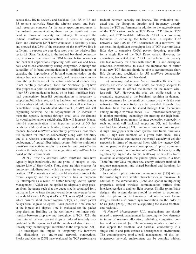
130 IEEE COMMUNICATIONS SURVEYS & TUTORIALS, VOL. 21, NO. 1, FIRST QUARTER 2019
access (i.e., BS to device), and backhaul (i.e., BS to BS andBS to core network). Since the wireless access and back-haul resources compete for the same spectrum resources inthe in-band communication, there can be significant over-head in terms of capacity and latency. To analyze thein-band mmWave communications in terms of capacity,Taori and Sridharan [267] have conducted a feasibility studyand showed that 25% of the resources of the mmWave link issufficient to support the user data rates over the wireless linkup to 0.8 Gbps. Typically, in the in-band backhaul connectiv-ity, the resources are shared in TDM fashion between wirelessand backhaul applications impacting both wireless and back-haul end-to-end connectivity during congestion. Although thesuitability of in-band communication is justified in terms ofcapacity, the implications of in-band communication on thelatency has not been characterized, and hence can compro-mise the performance of the entire end-to-end connectivityif not carefully considered. Taori and Sridharan [267] havealso proposed a point-to-multipoint transmission for BS to BS(inter-BS) communication based on in-band mmWave back-haul connectivity. Inter-BS communication is necessary tosupport mobility features, such as handover and redirection, aswell as advanced radio features, such as inter cell interferencecancellation using Coordinated MultiPoint (CoMP) and selforganizing networks. As the deployments of BS increase tomeet the capacity demands through small cells, the demandfor coordination among neighboring BSs will increase. Hence,inter-BS communication is an important aspect of 5G thatneeds be addressed in a flexible, simple and cost effectivemanner. In-band mmWave connectivity provides a cost effec-tive solution for inter-BS connectivity along with flexibilitydue to a wireless connection, as compared to the physicaldeployment of optical fiber infrastructure. Point-to-multipointmmWave connectivity results in a simpler and cost effectivesolution through a dynamic reconfiguration of mmWave linksbased on the requirements.
d) TCP over 5G mmWave links: mmWave links havetypically high bandwidths, but are prone to outages as theyrequire Line-of-Sight (LoS). Thus, there are high chances fortemporary link disruptions, which can result in temporary con-gestion. TCP congestion control could negatively impact theoverall capacity and the latency when a link is temporar-ily interrupted as a result of buffer bloating. Active QueueManagement (AQM) can be applied to adaptively drop pack-ets from the queue such that the queue size is contained for aparticular flow to keep the end-to-end delay on average belowa threshold. Control Delay (CoDel) [321] is an AQM techniquewhich ensures short packet sojourn delays, i.e., short packetdelays from ingress to egress. Each packet is time-stampedat the ingress and elapsed time is evaluated for the packetdrop decision. Building on the well-known non-linear rela-tionship between drop rate and throughput in TCP [322], thetime interval between packet drops is reduced inversely pro-portional to the square root of the number of drops so as tolinearly vary the throughput in relation to the drop count [321].
To investigate the impact of temporary 5G mmWavelink disruptions on end-to-end network connections,Pieska and Kassler [268] have evaluated the TCP performance
tradeoff between capacity and latency. The evaluation indi-cated that the disruption duration and frequency directlyimpact the TCP performance in addition to the aggressivenessof the TCP variant, such as TCP Reno, TCP Illinois, TCPcubic, and TCP Scalable. Although CoDel is a promisingtechnique in curtailing the buffer bloat in regular TCPnetworks, Non-LoS (NLOS) occurrences of a mmWave linkcan result in significant throughput loss of TCP over mmWavelinks due to extensive CoDel packet dropping, especiallyfor a single flow of the TCP Reno variant. However, theevaluations indicated that CoDel can achieve low latencyand fast recovery for flows with short RTTs and disruptiondurations. Nevertheless, to avoid the implications of bufferbloat, new TCP designs should be able to accommodate shortlink disruptions, specifically for 5G mmWave connectivityfor access, fronthaul, and backhaul.
e) Summary and lessons learnt: Small cells where thedevices are close to the radio nodes are widely adopted tosave power and to offload the burden on the macro wire-less cells [323]. However, the small cell traffic needs to beeventually aggregated at the backhaul, resulting in demand-ing requirements for the small cell connectivity with the corenetworks. The connectivity can be provided through fiberbackhaul links that can be shared through FiWi techniquesamong multiple wireless nodes [239]. mmWave technologyis another promising technology for meeting the high band-width and ULL requirements for next generation connectivity,such as, small cell backhaul supporting 5G, and fronthauland backhaul sharing [324]. mmWave wireless links supporti) high throughputs with short symbol and frame durations,and ii) high user numbers at a given radio node. Thus,mmWave backhaul can increase the overall capacity of cellularnetworks in terms of supported flows with low-latency QoS.As compared to the power consumption of optical communi-cations, the power consumption of mmWave links is typicallysignificantly higher due to the scattering of wireless trans-missions as compared to the guided optical waves in a fiber.Therefore, mmWave requires new energy efficient methods inresource management and shared backhaul and fronthaul for5G applications.
In contrast, optical wireless communication [325] utilizesthe visible light with similar characteristics as mmWave. Inaddition to the directionality (LoS) and spatial multiplexingproperties, optical wireless communication suffers frominterferences due to ambient light sources. Similar to mmWavedesigns, the system design should be robust to accommo-date disruptions due to temporary link obstructions. Futuredesigns should also ensure synchronization on the order of65 ns [168], [242], [326] while supporting the shared fronthauland backhaul.
4) Network Management: ULL mechanisms are closelyrelated to network management for meeting the flow demandsin terms of resource allocation, reliability, congestion con-trol, and end-to-end QoS. The increasing number of protocolsthat support the fronthaul and backhaul connectivity in asingle end-to-end path creates a heterogeneous environment.The comprehensive (end-to-end) management of this het-erogeneous network environment can be complex without

NASRALLAH et al.: ULL NETWORKS: IEEE TSN AND IETF DETNET STANDARDS AND RELATED 5G ULL RESEARCH 131
the support of an inter-operative mechanism. Managementmechanisms based on Software Defined Network (SDN) couldprovide a single platform for the coordination of a multitudeof protocols [327]–[330].
a) Integrated fronthaul and backhaul architecture: BothDistributed-RAN (DRAN) and CRAN offer unique deploy-ment options for cellular operators to enable cellular con-nectivity to the users. DRAN conducts the baseband signalprocessing at the remote Base Station (BS). As a result, theBS to core network (backhaul) connectivity has relaxed QoSrequirements and thus can be leased in the access networkdomain. On the other hand, CRANs require dedicated fiberlinks (typically owned by the cellular operator) for connect-ing the radio nodes to the core networks. Therefore, 5Gnetworks are expected to uniformly support DRAN and CRANarchitectures for enabling cellular connectivity to the users.
Jungnickel et al. [269] have proposed an integrated fronthauland backhaul based on SDN to commonly support DRAN andCRAN deployments for cellular operators. Traditional Ethernetdeployment strategies [331], such as the E-tree, can be adaptedfor the CRAN, and the E-LAN for D-RAN based on theirtopology support. To utilize the existing fiber, independentwavelengths can be used to meet the latency and capacityrequirements of the fronthaul and backhaul. For example, thebackhaul can use TDM within a single wavelength that isshared among multiple radio nodes, and the fronthaul requiresa dedicated wavelength between radio node and CRAN.However, the sharing of traditional access networks in E-Treeand E-LAN mode can cause security issues. Nevertheless,SDN provides both flexibility of statistical multiplexing inboth the optical and electrical domains, and security throughthe virtualization of the network infrastructure. In a similarstudy, Ameigeiras et al. [332] have proposed a hierarchicalSDN architecture based on virtualization, as well as Ethernetand IPv6 technologies focusing on low latency.
b) Optical wireless networking: The inter-working ofoptical and wireless technologies has been explored in FiWinetworks [333]–[335] and in the general context of optical-wireless integration in access and metro networks [336]–[340].As next-generation applications demand ULL and high relia-bility, there is a great need to integrate optical and wirelesstechnologies with minimal impact on the traditional cel-lular infrastructures, such as 4G LTE. Towards this end,the 5G STEP-FWD project [245] has been funded by theEuropean Commission to develop novel networking solutionsthat closely integrate the optical and wireless technologieswithin the 5G framework.
Vardakas et al. [245] have proposed a high capacity andlow latency 5G backhaul architecture as illustrated in Fig. 35.Network densification is supported by small cells which areconnected to macro BSs through PONs, mainly: i) OpticalLine Terminals (OLTs) connected through fiber links, ii) point-to-point dedicated links, and iii) local Optical Network Unit(ONU) connections through a fiber protection ring offered bydark fiber. The dark fiber utilization provides a cost effectivesolution as the infrastructure already exists. The wirelessaccess by the small cells and backhaul connectivity supportedby PONs are controlled by a unified SDN management
Fig. 35. Simplified version of ULL optical wireless architecture whereWDM ring connects to wireless nodes and SDN controller through PONframework [245].
framework. mmWave-UDWDM technology effectively uti-lizes the wavelength and space division multiplexing, whilePONs provide effective backhaul connectivity. The SDNmanagement can support dynamic reconfigurability to supportadvanced network features, such as self-organization andself-healing for ultra-reliable infrastructure networks.
c) SDN based evolved packet core (EPC) networks:Pagé and Dricot [270] have presented an SDN architecture forthe LTE Evolved Packet Core (EPC) to support low-latencytowards an evolutionary 5G core network. OpenFlow technol-ogy has been integrated into the switching nodes that connectthe BSs (i.e., eNBs) to the EPC. The advantages of SDN basedswitching include reduced need for protocol based transportservices, such as GTP, elimination of the Serving-Gateway(S-GW) which conventionally provides flow based services,such as buffering and connection management. In contrast tothe conventional LTE backhaul connectivity, where the S-GWanchors the connections of the eNBs to the P-GW, the SDNbased EPC is managed by an SDN controller, which replacesthe S-GW control plane functions. The S-GW data plane func-tions are replaced by the SDN supported switching nodes.Thus, the SDN architecture eliminates the data and controlbearer based connectivity [341] by replacing the large GTPmessages with small SDN control messages. Additionally, theSDN based switching nodes can assist in attach and mobilityprocedures to reduce the overall load on the EPC core. As aresult, the overall end-to-end latency can be reduced by reduc-ing the data plane and control plane latency introduced by theintermediate nodes in the EPC core.
d) Dynamic gateway placement: Lakkakorpi et al. [271]have proposed a low latency technique in an SDN based back-haul network architecture that is fully reconfigurable. Thegateway functions and queue management are configured toachieve low latency by minimizing the flow reestablishmentprocedures. The SDN controller dynamically programs theswitching nodes to implement the network functions based onthe flow characteristics. More specifically, an anchor switchingnode is dynamically selected to implement the gateway func-tions and AQM based on the flow mobility characteristics.

132 IEEE COMMUNICATIONS SURVEYS & TUTORIALS, VOL. 21, NO. 1, FIRST QUARTER 2019
For instance, in case of frequent handovers, the flow pathmust often be reconfigured to pass from one gateway func-tion node to another. Therefore, the gateway functions canbe implemented deeper in the core networks for the specificflows with frequent handovers, such that only the path routingis updated during handovers. This implementation of the gate-way functions in the core networks also distributes the gatewayfunctions across the switching nodes, reducing the overallburden on the core network.
e) Summary and lessons learnt: In addition to theoptimization of handover latencies in the wireless access, thebackhaul architecture should support lower handover laten-cies. Chen and Li [342] have discussed the need for efficientbackhaul architecture to support ultra-short handover latencies.However, the discussions are limited to DBA mechanisms inPONs for optimizing the LTE X2 and S1 interfaces.
In 5G technology, handovers can cause temporary disrup-tions to large data flows which can result in buffer-bloatproblems across the network. New congestion control mech-anisms must be adapted to address the short and temporarydisruptions due to handovers during large data transfers. SDNbased strategies can help to address these challenging handoverproblems [343]. However, existing studies have not consideredthe control plane latency and complexity, which may signifi-cantly impact the overall end-to-end latency. Therefore whileensuring the flexibility and reliability in 5G networks, it is alsoimportant to consider the end-to-end latency, through infras-tructure based solutions, such as, dense wavelength-divisionmultiplexed (DWDM) optical ring transport networks [344]using dark fiber, which is both energy and cost efficient.
5) Discussion on ULL 5G Research Studies: There havebeen numerous research efforts in the wireless access seg-ment of 5G networks. However, there is still a need forresearch to solve compelling technical challenges [345] inenabling ultra-reliable ULL communication. These researchchallenges include infrastructure reuse, as well as cost andpower efficiency. Throughout, the implications of wirelessaccess techniques on ULL services should be carefully consid-ered. For instance, the emerging 5G New Radio (NR) platformproposes new waveform designs. The symbol and frame dura-tions as well as the guard band durations (e.g., cyclic prefixesin the OFDM symbol) in these new waveforms would directlyimpact ULL services. Increasingly complex waveforms wouldrequire longer symbols and longer frames, not only because oflimited receiver processing capabilities, but also to maintainthe synchronous delay between uplink and downlink mes-sages. Thus, increasing the waveform complexity would tendto increase the wireless round trip delay. Moreover, the chan-nel characteristics, such as the maximum (mobility) speed of5G user devices and the cell size influence the guard bandduration. For example, a high speed train scenario requires arelatively long doppler correction. Similarly, rural deploymentsrequire large cells. In both situations, a long guard band (cyclicprefix) is preferred such that the inter symbol interference canbe minimized. A long guard band (cyclic prefix) would implyrelatively long symbols and frames which could negativelyaffect ULL services. Thus, the new waveform designs in the5G platform should carefully consider the impact on ULLservices throughout the development process.
With the radio node densification, user mobility betweenradio nodes is expected to increase dramatically, which cansignificantly increase the control plane complexity in terms ofuser context updates in the core networks. Therefore, a lightweight (i.e., reduced user context) user information set mustbe managed by the core networks, as opposed to intense policyand security mechanisms that contribute to control plane com-plexity. End-to-end security can reduce the burden of securitymeasures by the core network. Similarly, user activities canbe tracked by the radio node to enforce the policy and QoSmeasures across the network.
SDN plays an important role not only for managing fron-thaul, backhaul, and core networks, but also for reducing thenetwork complexity by reducing the network function imple-mentation in dedicated entities, such as policy enforcementand user authentication. SDN can also integrate the hetero-geneous protocol operations through dynamic packet headermanipulation such that the protocol overheads are minimized.
Content caching in edge nodes has been widely discussedfor reducing the delivery latency in fog-RAN and edgecomputing domains [346]–[349]. SDN provides a platformfor caching content across the entire network as well asbased on user demands, optimizing both content cachingand latency. Although 5G technology is primarily focusedon power optimization of user devices and wireless radionodes [350]–[352], the overall energy consumption of thenetwork responsible for the end-to-end packet delivery shouldalso be considered in future designs.
VIII. FUTURE WORK DIRECTIONS
In this section we discuss the main open TSN and DetNetresearch problems and outline directions for future researchefforts in TSN and DetNet networks.
A. Time Sensitive Networks (TSN)
1) Inter-Scheduler Coordination: Time aware sharpersimplement local scheduling principles specific to each TSNnode. The end-to-end time sensitive characteristics of a floware established under the assumption that each TSN node inthe flow path guarantees the time sensitive characteristics.However, if an intermediate TSN node fails to enforce theTSN characteristics due to overload, or due to scheduler ortiming inaccuracies, the overall end-to-end flow characteris-tics can be compromised. This situation may be more likelyfor TSN nodes that are positioned where multiple flows canaggregate as opposed to the edge nodes (that are traversed byonly few flows).
To address this shortcoming, future research should developa robust inter-scheduler coordination mechanism. The coordi-nation mechanism should facilitate interactions between thetime aware shapers in the TSN nodes in a flow path to ensurethe overall end-to-end time sensitive characteristics of theflow. For instance, upon frame reception at the destination,the overall end-to-end latency can be estimated and the infor-mation can be fed back to the nodes. The TSN nodes canthen establish a self performance profile. The interactions ofthe time aware shapers would enable inter-scheduler coordina-tion such that each TSN node can guarantee the time sensitive
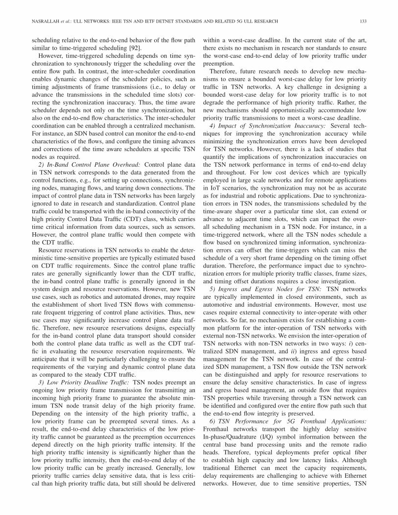
NASRALLAH et al.: ULL NETWORKS: IEEE TSN AND IETF DETNET STANDARDS AND RELATED 5G ULL RESEARCH 133
scheduling relative to the end-to-end behavior of the flow pathsimilar to time-triggered scheduling [92].
However, time-triggered scheduling depends on time syn-chronization to synchronously trigger the scheduling over theentire flow path. In contrast, the inter-scheduler coordinationenables dynamic changes of the scheduler policies, such astiming adjustments of frame transmissions (i.e., to delay oradvance the transmissions in the scheduled time slots) cor-recting the synchronization inaccuracy. Thus, the time awarescheduler depends not only on the time synchronization, butalso on the end-to-end flow characteristics. The inter-schedulercoordination can be enabled through a centralized mechanism.For instance, an SDN based control can monitor the end-to-endcharacteristics of the flows, and configure the timing advancesand corrections of the time aware schedulers at specific TSNnodes as required.
2) In-Band Control Plane Overhead: Control plane datain TSN network corresponds to the data generated from thecontrol functions, e.g., for setting up connections, synchroniz-ing nodes, managing flows, and tearing down connections. Theimpact of control plane data in TSN networks has been largelyignored to date in research and standardization. Control planetraffic could be transported with the in-band connectivity of thehigh priority Control Data Traffic (CDT) class, which carriestime critical information from data sources, such as sensors.However, the control plane traffic would then compete withthe CDT traffic.
Resource reservations in TSN networks to enable the deter-ministic time-sensitive properties are typically estimated basedon CDT traffic requirements. Since the control plane trafficrates are generally significantly lower than the CDT traffic,the in-band control plane traffic is generally ignored in thesystem design and resource reservations. However, new TSNuse cases, such as robotics and automated drones, may requirethe establishment of short lived TSN flows with commensu-rate frequent triggering of control plane activities. Thus, newuse cases may significantly increase control plane data traf-fic. Therefore, new resource reservations designs, especiallyfor the in-band control plane data transport should considerboth the control plane data traffic as well as the CDT traf-fic in evaluating the resource reservation requirements. Weanticipate that it will be particularly challenging to ensure therequirements of the varying and dynamic control plane dataas compared to the steady CDT traffic.
3) Low Priority Deadline Traffic: TSN nodes preempt anongoing low priority frame transmission for transmitting anincoming high priority frame to guarantee the absolute min-imum TSN node transit delay of the high priority frame.Depending on the intensity of the high priority traffic, alow priority frame can be preempted several times. As aresult, the end-to-end delay characteristics of the low prior-ity traffic cannot be guaranteed as the preemption occurrencesdepend directly on the high priority traffic intensity. If thehigh priority traffic intensity is significantly higher than thelow priority traffic intensity, then the end-to-end delay of thelow priority traffic can be greatly increased. Generally, lowpriority traffic carries delay sensitive data, that is less criti-cal than high priority traffic data, but still should be delivered
within a worst-case deadline. In the current state of the art,there exists no mechanism in research nor standards to ensurethe worst-case end-to-end delay of low priority traffic underpreemption.
Therefore, future research needs to develop new mecha-nisms to ensure a bounded worst-case delay for low prioritytraffic in TSN networks. A key challenge in designing abounded worst-case delay for low priority traffic is to notdegrade the performance of high priority traffic. Rather, thenew mechanisms should opportunistically accommodate lowpriority traffic transmissions to meet a worst-case deadline.
4) Impact of Synchronization Inaccuracy: Several tech-niques for improving the synchronization accuracy whileminimizing the synchronization errors have been developedfor TSN networks. However, there is a lack of studies thatquantify the implications of synchronization inaccuracies onthe TSN network performance in terms of end-to-end delayand throughout. For low cost devices which are typicallyemployed in large scale networks and for remote applicationsin IoT scenarios, the synchronization may not be as accurateas for industrial and robotic applications. Due to synchroniza-tion errors in TSN nodes, the transmissions scheduled by thetime-aware shaper over a particular time slot, can extend oradvance to adjacent time slots, which can impact the over-all scheduling mechanism in a TSN node. For instance, in atime-triggered network, where all the TSN nodes schedule aflow based on synchronized timing information, synchroniza-tion errors can offset the time-triggers which can miss theschedule of a very short frame depending on the timing offsetduration. Therefore, the performance impact due to synchro-nization errors for multiple priority traffic classes, frame sizes,and timing offset durations requires a close investigation.
5) Ingress and Egress Nodes for TSN: TSN networksare typically implemented in closed environments, such asautomotive and industrial environments. However, most usecases require external connectivity to inter-operate with othernetworks. So far, no mechanism exists for establishing a com-mon platform for the inter-operation of TSN networks withexternal non-TSN networks. We envision the inter-operation ofTSN networks with non-TSN networks in two ways: i) cen-tralized SDN management, and ii) ingress and egress basedmanagement for the TSN network. In case of the central-ized SDN management, a TSN flow outside the TSN networkcan be distinguished and apply for resource reservations toensure the delay sensitive characteristics. In case of ingressand egress based management, an outside flow that requiresTSN properties while traversing through a TSN network canbe identified and configured over the entire flow path such thatthe end-to-end flow integrity is preserved.
6) TSN Performance for 5G Fronthaul Applications:Fronthaul networks transport the highly delay sensitiveIn-phase/Quadrature (I/Q) symbol information between thecentral base band processing units and the remote radioheads. Therefore, typical deployments prefer optical fiberto establish high capacity and low latency links. Althoughtraditional Ethernet can meet the capacity requirements,delay requirements are challenging to achieve with Ethernetnetworks. However, due to time sensitive properties, TSN

134 IEEE COMMUNICATIONS SURVEYS & TUTORIALS, VOL. 21, NO. 1, FIRST QUARTER 2019
Ethernet is being considered as a potential candidate L2 pro-tocol for 5G fronthaul applications as an alternative to theCommon Public Radio Interface (CPRI) and eCPRI [243]protocols. The adoption of TSN for existing Ethernet infras-tructures could result in significant capital and operatingexpenditures for new fiber deployments (e.g., if an eCPRIwireless link is replaced by a TSN fiber link). But, theactual performance of TSN networks for fronthaul applica-tions has not yet been investigated for the various fronthaulsplits [285]. The PHY and sub-PHY splits require strict dead-lines on the order of sub-microseconds. On the other hand,function splits in the MAC, Radio Resource Control (RRC),and higher cellular protocol layers relax the delay requirementsto the order of milliseconds. A comprehensive performanceevaluation considering the full range of aspects of fronthaulapplications, such as relative performance between EthernetPassive Optical Networks (EPONs) and TSN Ethernet, pack-etization, functional split, and fronthaul distances for a CloudRadio Access Network (CRAN) system could provide deepinsight towards deployment considerations for mobile opera-tor networks. The ULL requirements of a wide range of 5Gwireless network applications and services have been exten-sively documented, see [3], [41], [231], [233]–[240], [272],[276], [277], [345], [346], [350], [353]–[370]. Thus, there is anextensive need to research latency reductions for 5G wirelessnetworks. Investigating the combined impacts of the variouslatency reduction techniques developed in future 5G wirelessnetwork studies in conjunction with TSN based fronthaul isan important direction for future research.
7) TSN Applied to Wide Area Networks: The time-sensitiveprotocol mechanisms that are applied to micro-environments,such as automotive networks, can also be applied to macro-environments, such as Wide Area Networks (WANs). In mostsituations, the end-to-end network delay is dominated by thewait time in the queues (buffers) of intermediate forwardingnodes. With the TSN rules applied to nodes, the overall end-to-end delay of a flow over a WAN network can be significantlyreduced. However, WAN networks typically handle large num-bers of flows and operate at very large capacities, makingthe TSN flow management very challenging. Despite thesechallenges, WAN networks should, in principle, be capable ofsupporting TSN characteristics for specific flows that requirestrict end-to-end latency bounds, such as remote surgery inhealth-care applications, where a doctor could operate on apatient across a WAN network. One possible approach to han-dle the challenging flow management could be through SDNbased control. The large geographical WAN area would likelyrequire an SDN control hierarchy consisting of multiple con-trol plane entities, such as, local and root controllers, as wellan orchestrator.
B. Deterministic Networking (DetNet)
1) Packet Replication and Elimination: Packet replicationinherently increases the flow reliability by increasing the prob-ability of packet delivery to the end destination. Additionally,packet replication can reduce the overall end-to-end latencydue to disjoint paths [226]. However, a major disadvantage of
packet replication is the increase in the effective bandwidthrequired for a flow. The required bandwidth can be decreasedby reducing the degree of replication, which can effectivelyreduce the reliability. Thus, a balance between bandwidth anddegree of packet replication must be ensured to operate thenetwork within the required bandwidth (capacity) and latencylimitations.
Towards this end, we propose a reverse packet eliminationmechanism in which the destination node triggers an instruc-tion to the nodes in the reverse path to apply a packet dropaction. For instance, consider the forward direction of a flowwith four disjoint paths, i.e., each packet is replicated fourtimes. These replicated packets traverse independently acrossthe disjoint paths through the network to reach the commonend destination. We can assume that one packet will arriveearlier than the others, considering that multiple packets willlikely arrive at the destination. In the current implementation,the other packets are discarded when they eventually arriveat the destination. Thus, the effective bandwidth is four foldincreased in the forward direction.
In a DetNet/SDN framework, the destination node can bemade aware of the exact nodes traversed by the different paths.That is, for a given path with node 0 denoting the sourcenode and node n denoting the destination node, the destina-tion node knows the n − 1 intermediate nodes. If there issufficient bandwidth in the reverse direction, the destinationnode can send a short drop-packet in the reverse direction onpaths through which the destination node has not yet receivedthe packets; upon reception of a drop-packet, the intermediatenodes drop the forward packet. This drop-packet would tra-verse backwards through the nodes n − 1, n − 2, . . . towardsthe source node while applying the rule to drop until thedrop-packet meets the forward packet. Thus, because of thereverse back propagation of the drop-packet, some of the for-ward direction bandwidth is freed up. In many networkingscenarios, the ratio of uplink traffic to downlink traffic is low,and therefore the uplink can typically readily accommodatethe reverse back propagation of the small drop-packet noti-fications. Future research would need to conduct a rigorousperformance study of the proposed drop-packet approach fora wide range of network conditions, such as number of flows,relative delay in diversity paths, and numbers of intermediatepaths.
2) Virtualization: L2 Independent Mechanisms: AlthoughDetNet focuses on the network layer (L3) and higher layers,DetNet relies on the time sensitive link layer (L2) to establishthe deterministic L3 packet flow properties. Therefore, pro-moting DetNet mechanisms which are independent of the timesensitive link layer could result in the wide adoption of DetNetdue to the simple and cost-effective infrastructure support. Forinstance, packet replication and fragmentation do not requiretiming information and can be implemented independently ofthe link layer. One way to achieve independence from thelink layer is through Network Function Virtualization (NFV),which can dynamically scale the resource reservations basedon the flow demands. However, such NFV mechanisms wouldrequire hypervisor and control plane management [371]–[375].NFV also provides a platform for centralized control plane

NASRALLAH et al.: ULL NETWORKS: IEEE TSN AND IETF DETNET STANDARDS AND RELATED 5G ULL RESEARCH 135
management through the SDN framework. Thus, througha unique combination of SDN and NFV, DetNet can beindependently adapted to networks without time sensitive linklayer properties.
3) Inter-Networking: The DetNet inter-networking with anexternal network (i.e., a non-DetNet network) is still an openissue. Generally, a DetNet requires an centralized in-domaincontroller to establish an end-to-end placket flow. Therefore, ifan external flow needs to traverse a DetNet network, the flowrequirements must be configured within the DetNet network.Ingress and egress nodes could be introduced to manage theconfigurations for the incoming and outgoing external flows.In particular, an ingress node could perform admission con-trol to make flow accept/reject decisions. The ingress nodewould then also track and manage the packet flows. During thisprocess, the ingress node could cooperate with the DetNet cen-tralized control entity, e.g., a Path Computing Element (PCE),to accomplish the flow setup over the DetNet network. Thus,the cooperation between ingress node and PCE would enablethe inter-networking of DetNet and non-DetNet networks. Ofparticular importance will be the study of interactions withdata center networks. Latency reduction techniques for datacenter networks have received increasing attention in recentyears, see for instance [376]–[406]. Thus, it will be importantthe extend DetNet into the data center networking domain.
4) Application-Adaptive Resource Reservations: With theincreasing number of applications on end user devices thatrequire network connectivity, the diversity of the traffic typeshas been increasing. Traditional data included voice and user-data, such as files and media, while the present data sourcesinclude sensor data as well as tracking and analytics informa-tion. Time sensitive advanced applications in the automotiveand industrial sectors require special transmission resourcereservations to meet their ULL requirements. Therefore, webelieve application-based resource reservations in L2 and PHY(i.e., proactive grants, periodic grants, and semi-persistentscheduling) across the entire network are a promising tech-nique to achieve the fundamental limits of ULL end-to-endlatency for the users.
5) Integration and Support for 5G Backhaul Networks: Tomeet the growing data demands of ubiquitous mobile devices,5G networks are expected to increase the infrastructure deploy-ments through small cells. The small cells are deployed closeto the users/devices, such as in shopping malls, stadiums, andon university campuses. However, the deployment of largenumbers of small cells increases the backhaul network com-plexity. Backhaul for small cells requires deterministic latencyfor establishing secure IP layer connectivity with the corenetworks. DetNet can provide backhaul connectivity for thesmall cells in 5G networks. However, the integration of DetNetat the protocol level (e.g., GPRS Tunneling Protocol (GTP)and IPSec) with the existing cellular networks is yet to bethoroughly investigated. Key challenges are to achieve a lowcomplexity overall control plane management as well as tokeep the impact on the existing 5G control plane minimal.
C. 5G Networks
1) Seamless Networks Access: Although 5G is envisionedto support ULL and high data rates in both the wireless air
interface and the core networks, the seamless network accessacross multiple operators and connectivity technologies, suchas cable and DSL networks, is still an open issue in termsof inter-networking functions. The inter-networking functionsacross multiple networks and technology domains must be ableto negotiate the same set of services while the devices areoperating in the 5G domain.
2) Network Session Migration: The current network con-nectivity technology trends, including the 5G technologytrends, enumerate several network interfaces that concurrentlyconnect a user device to different networks, such as WiFi,LTE, 3G, and Ethernet. However, the actual network char-acteristics of each interface change over time. For instance,in cellular communications the transmit power is proportionalto the distance from the base stations. Hence due to devicemobility, the transmit power varies based on the relative dis-tance between base station and device. While there exists astatic way of choosing the network interface based on appli-cation requirement [407], a dynamic selection based on thenetwork interface characteristics in real time remains an openresearch challenge. Additionally, once a session is establishedover an interface, any changes in the network characteristicsthat impede the connection quality would negatively impactthe end-to-end latency. To maintain low latencies, an activesession should be handed over to a different interface withoutinterrupting the session.
IX. CONCLUSION
This survey has comprehensively covered networks sup-porting ultra-low latency (ULL) applications. Providing ULLsupport requires specialized network protocol mechanisms thathave been standardized for the link layer in the IEEE TimeSensitive Networking (TSN) set of standards and for thenetwork layer in the IETF Deterministic Networking (DetNet)specifications. In addition, extensive research studies havebegun to investigate in detail the performance characteristicsand limitations of these link and network layer ULL mech-anisms. Aside from this link and network layer perspective,extensive standardization and research efforts have approachedULL support from the perspective of the common wirelessdevice-to-core network communication chain. In particular,the emerging fifth generation (5G) wireless systems provideextensive support mechanisms for ULL applications.
The survey has revealed numerous gaps and limitations ofthe existing ULL networking mechanisms that present a widerange of avenues for future research. Aside from addressingthe limitations of the individual ULL support mechanisms,there is an urgent need to comprehensively evaluate the coop-eration of the various developed ULL mechanisms. Judiciousconfiguration and cooperation of the various ULL mechanismswill likely be critical for providing effective ULL services tothe end users.
REFERENCES
[1] M. Wollschlaeger, T. Sauter, and J. Jasperneite, “The future of indus-trial communication: Automation networks in the era of the Internetof Things and industry 4.0,” IEEE Ind. Electron. Mag., vol. 11, no. 1,pp. 17–27, Mar. 2017.
136 IEEE COMMUNICATIONS SURVEYS & TUTORIALS, VOL. 21, NO. 1, FIRST QUARTER 2019
[2] G. P. Fettweis, “The tactile Internet: Applications and challenges,”IEEE Veh. Technol. Mag., vol. 9, no. 1, pp. 64–70, Mar. 2014.
[3] M. Maier, M. Chowdhury, B. P. Rimal, and D. P. Van, “The tactileInternet: Vision, recent progress, and open challenges,” IEEE Commun.Mag., vol. 54, no. 5, pp. 138–145, May 2016.
[4] A. Finzi, A. Mifdaoui, F. Frances, and E. Lochin, “IncorporatingTSN/BLS in AFDX for mixed-criticality avionics applications:Specification and analysis,” arXiv preprint arXiv:1707.05538, 2017.
[5] P. Schulz et al., “Latency critical IoT applications in 5G: Perspective onthe design of radio interface and network architecture,” IEEE Commun.Mag., vol. 55, no. 2, pp. 70–78, Feb. 2017.
[6] S. Samii and H. Zinner, “Level 5 by layer 2: Time-sensitive networkingfor autonomous vehicles,” IEEE Commun. Stand. Mag., vol. 2, no. 2,pp. 62–68, Jun. 2018.
[7] D. Delaney, T. Ward, and S. McLoone, “On consistency and networklatency in distributed interactive applications: A survey—Part I,”Presence Teleoper. Virtual Environ., vol. 15, no. 2, pp. 218–234,Apr. 2006.
[8] D. Delaney, T. Ward, and S. McLoone, “On consistency and networklatency in distributed interactive applications: A survey—Part II,”Presence Teleoper. Virtual Environ., vol. 15, no. 4, pp. 465–482,Aug. 2006.
[9] C. S. V. Gutiérrez, L. U. S. Juan, I. Z. Ugarte, and V. M. Vilches, “Time-sensitive networking for robotics,” arXiv preprint arXiv:1804.07643,2018.
[10] F. Prinz, M. Schoeffler, A. Lechler, and A. Verl, “Dynamic real-timeorchestration of I4.0 components based on time-sensitive networking,”Procedia CIRP, vol. 72, pp. 910–915, Jun. 2018.
[11] C. Bachhuber, E. Steinbach, M. Freundl, and M. Reisslein, “On theminimization of glass-to-glass and glass-to-algorithm delay in videocommunication,” IEEE Trans. Multimedia, vol. 20, no. 1, pp. 238–252,Jan. 2018.
[12] E. Gardiner, “The Avnu alliance theory of operation for TSN-enabledindustrial systems,” IEEE Commun. Stand. Mag., vol. 2, no. 1, p. 5,Mar. 2018.
[13] A. Aijaz, M. Simsek, M. Dohler, and G. Fettweis, “Shaping 5G for thetactile Internet,” in 5G Mobile Communications. Cham, Switzerland:Springer, 2017, pp. 677–691.
[14] A. Aijaz, M. Dohler, A. H. Aghvami, V. Friderikos, and M. Frodigh,“Realizing the tactile Internet: Haptic communications over next gen-eration 5G cellular networks,” IEEE Wireless Commun., vol. 24, no. 2,pp. 82–89, Apr. 2017.
[15] K. Antonakoglou, X. Xu, E. Steinbach, T. Mahmoodi, and M. Dohler,“Towards haptic communications over the 5G tactile Internet,” IEEECommun. Surveys Tuts., to be published.
[16] R. A. Delgado, K. Lau, R. H. Middleton, and T. Wigren, “Networkeddelay control for 5G wireless machine-type communications usingmulticonnectivity,” IEEE Trans. Control Syst. Technol., to bepublished.
[17] B. Briscoe et al., “Reducing Internet latency: A survey of tech-niques and their merits,” IEEE Commun. Surveys Tuts., vol. 18, no. 3,pp. 2149–2196, 3rd Quart., 2016.
[18] M. Lévesque and D. Tipper, “A survey of clock synchronization overpacket-switched networks,” IEEE Commun. Surveys Tuts., vol. 18,no. 4, pp. 2926–2947, 4th Quart., 2016.
[19] Y. Luo, F. J. Effenberger, and N. Ansari, “Time synchronization overEthernet passive optical networks,” IEEE Commun. Mag., vol. 50,no. 10, pp. 136–142, Oct. 2012.
[20] J. W. Guck, A. Van Bemten, M. Reisslein, and W. Kellerer, “UnicastQoS routing algorithms for SDN: A comprehensive survey andperformance evaluation,” IEEE Commun. Surveys Tuts., vol. 20, no. 1,pp. 388–415, 1st Quart. 2018.
[21] S. M. Laursen, P. Pop, and W. Steiner, “Routing optimization ofAVB streams in TSN networks,” ACM SIGBED Rev., vol. 13, no. 4,pp. 43–48, Sep. 2016.
[22] R. B. da Silva and E. S. Mota, “A survey on approaches to reduceBGP interdomain routing convergence delay on the Internet,” IEEECommun. Surveys Tuts., vol. 19, no. 4, pp. 2949–2984, 4th Quart.,2017.
[23] J. Luo, J. Jin, and F. Shan, “Standardization of low-latency TCP withexplicit congestion notification: A survey,” IEEE Internet Comput.,vol. 21, no. 1, pp. 48–55, Jan./Feb. 2017.
[24] C. Xu, J. Zhao, and G.-M. Muntean, “Congestion control design formultipath transport protocols: A survey,” IEEE Commun. Surveys Tuts.,vol. 18, no. 4, pp. 2948–2969, 4th Quart., 2016.
[25] P. Mach and Z. Becvar, “Mobile edge computing: A survey on archi-tecture and computation offloading,” IEEE Commun. Surveys Tuts.,vol. 19, no. 3, pp. 1628–1656, 3rd Quart., 2017.
[26] C. Mouradian et al., “A comprehensive survey on fog computing:State-of-the-art and research challenges,” IEEE Commun. Surveys Tuts.,vol. 20, no. 1, pp. 416–464, 1st Quart., 2018.
[27] J. Ni, K. Zhang, X. Lin, and X. S. Shen, “Securing fog comput-ing for Internet of Things applications: Challenges and solutions,”IEEE Commun. Surveys Tuts., vol. 20, no. 1, pp. 601–628, 1st Quart.,2018.
[28] T. Taleb et al., “On multi-access edge computing: A survey of theemerging 5G network edge cloud architecture and orchestration,” IEEECommun. Surveys Tuts., vol. 19, no. 3, pp. 1657–1681, 3rd Quart.,2017.
[29] I. Al-Anbagi, M. Erol-Kantarci, and H. T. Mouftah, “A survey oncross-layer quality-of-service approaches in WSNs for delay andreliability-aware applications,” IEEE Commun. Surveys Tuts., vol. 18,no. 1, pp. 525–552, 1st Quart., 2016.
[30] M. Bennis, M. Debbah, and H. V. Poor, “Ultra-reliable and low-latency wireless communication: Tail, risk and scale,” arXiv preprintarXiv:1801.01270, 2018.
[31] M. Doudou, D. Djenouri, and N. Badache, “Survey on latency issuesof asynchronous MAC protocols in delay-sensitive wireless sensornetworks,” IEEE Commun. Surveys Tuts., vol. 15, no. 2, pp. 528–550,2nd Quart., 2013.
[32] R. Ford et al., “Achieving ultra-low latency in 5G millimeter wavecellular networks,” IEEE Commun. Mag., vol. 55, no. 3, pp. 196–203,Mar. 2017.
[33] P. Park, S. C. Ergen, C. Fischione, C. Lu, and K. H. Johansson,“Wireless network design for control systems: A survey,” IEEECommun. Surveys Tuts., vol. 20, no. 2, pp. 978–1013, 2nd Quart., 2018.
[34] I. Parvez, A. Rahmati, I. Guvenc, A. I. Sarwat, and H. Dai, “A surveyon low latency towards 5G: RAN, core network and caching solutions,”IEEE Commun. Surveys Tuts., to be published.
[35] G. J. Sutton et al., “Enabling ultra-reliable and low-latency commu-nications through unlicensed spectrum,” IEEE Netw., vol. 32, no. 2,pp. 70–77, Mar./Apr. 2018.
[36] M. Erol-Kantarci and H. T. Mouftah, “Energy-efficient information andcommunication infrastructures in the smart grid: A survey on interac-tions and open issues,” IEEE Commun. Surveys Tuts., vol. 17, no. 1,pp. 179–197, 1st Quart., 2015.
[37] D. Cerovic, V. D. Piccolo, A. Amamou, K. Haddadou, and G. Pujolle,“Fast packet processing: A survey,” IEEE Commun. Surveys Tuts., tobe published.
[38] A. Badr, A. Khisti, W.-T. Tan, and J. Apostolopoulos, “Perfecting pro-tection for interactive multimedia: A survey of forward error correctionfor low-delay interactive applications,” IEEE Signal Process. Mag.,vol. 34, no. 2, pp. 95–113, Mar. 2017.
[39] A. Douik, S. Sorour, T. Y. Al-Naffouri, and M.-S. Alouini, “Instantlydecodable network coding: From centralized to device-to-devicecommunications,” IEEE Commun. Surveys Tuts., vol. 19, no. 2,pp. 1201–1224, 2nd Quart., 2017.
[40] M. Fidler and A. Rizk, “A guide to the stochastic network calculus,”IEEE Commun. Surveys Tuts., vol. 17, no. 1, pp. 92–105, 1st Quart.,2015.
[41] M. Simsek, A. Aijaz, M. Dohler, J. Sachs, and G. Fettweis, “5G-enabled tactile Internet,” IEEE J. Sel. Areas Commun., vol. 34, no. 3,pp. 460–473, Mar. 2016.
[42] J. Eveleens, “Ethernet AVB overview and status,” in Proc. IEEESMPTE Tech. Conf. Exhibit., Oct. 2014, pp. 1–11.
[43] M. D. J. Teener et al., “Heterogeneous networks for audio and video:Using IEEE 802.1 audio video bridging,” Proc. IEEE, vol. 101, no. 11,pp. 2339–2354, Nov. 2013.
[44] K. Qian, F. Ren, D. Shan, W. Cheng, and B. Wang, “XpressEth:Concise and efficient converged real-time Ethernet,” in Proc.IEEE/ACM 25th Int. Symp. Qual. Service (IWQoS), 2017, pp. 1–6.
[45] M. Amjad, M. H. Rehmani, and S. Mao, “Wireless multimedia cogni-tive radio networks: A comprehensive survey,” IEEE Commun. SurveysTuts., vol. 20, no. 2, pp. 1056–1103, 2nd Quart., 2018.
[46] R. Trestian, I.-S. Comsa, and M. F. Tuysuz, “Seamless multimediadelivery within a heterogeneous wireless networks environment: Arewe there yet?” IEEE Commun. Surveys Tuts., vol. 20, no. 2,pp. 945–977, 2nd Quart., 2018.
[47] B. Cizmeci et al., “A multiplexing scheme for multimodal teleopera-tion,” ACM Trans. Multimedia Comput. Commun. Appl., vol. 13, no. 2,pp. 1–21, May 2017.

NASRALLAH et al.: ULL NETWORKS: IEEE TSN AND IETF DETNET STANDARDS AND RELATED 5G ULL RESEARCH 137
[48] S. Xu, M. Perez, K. Yang, C. Perrenot, J. Felblinger, and J. Hubert,“Determination of the latency effects on surgical performance and theacceptable latency levels in telesurgery using the dV-trainer simulator,”Surg. Endoscopy, vol. 28, no. 9, pp. 2569–2576, Sep. 2014.
[49] Q. Zhang, J. Liu, and G. Zhao, “Towards 5G enabled tactile robotictelesurgery,” arXiv preprint arXiv:1803.03586, 2018.
[50] B. Rudy et al., IEC/IEEE TSN Profile for Industrial Automation,document IEC/IEEE 60802 V0.61, IEC/IEEE, Piscataway, NJ, USA,Apr. 2018.
[51] C. C. Moallemi and M. Saglam, “The cost of latency in high-frequencytrading,” Oper. Res., vol. 61, no. 5, pp. 1070–1086, Oct. 2013.
[52] S. Schneele and F. Geyer, “Comparison of IEEE AVB and AFDX,”in Proc. IEEE/AIAA Digit. Avionics Syst. Conf. (DASC), 2012,pp. 1–9.
[53] Y. Kim and M. Nakamura. (Mar. 2011). Automotive EthernetNetwork Requirements. Accessed: Jul. 21, 2018. [Online].Available: http://www.ieee802.org/1/files/public/docs2011/new-avb-KimNakamura-automotive-network-requirements-0311.pdf
[54] J. Takeuchi. (Mar. 2011). Requirements for Automotive AVB SystemProfiles, White Paper Contributed to Avnu Alliance. Accessed:Jul. 21, 2018. [Online]. Available: http://avnu.org/wp-content/uploads/2014/05/Contributed-Automotive-Whitepaper_April-2011.pdf
[55] A. Osseiran et al., “Scenarios for 5G mobile and wireless communica-tions: The vision of the METIS project,” IEEE Commun. Mag., vol. 52,no. 5, pp. 26–35, May 2014.
[56] J. Huang, M. Zhao, Y. Zhou, and C.-C. Xing, “In-vehicle networking:Protocols, challenges, and solutions,” IEEE Netw., to be published.
[57] D. Chatzopoulos, C. Bermejo, Z. Huang, and P. Hui, “Mobile aug-mented reality survey: From where we are to where we go,” IEEEAccess, vol. 5, pp. 6917–6950, 2017.
[58] IEEE Standard for Local and Metropolitan Area Networks–Bridgesand Bridged Networks, IEEE Standard 802.1Q-2014, pp. 1–1832,Dec. 2014.
[59] R. M. Metcalfe and D. R. Boggs, “Ethernet: Distributed packet switch-ing for local computer networks,” Commun. ACM, vol. 19, no. 7,pp. 395–404, Jul. 1976.
[60] R. M. Metcalfe, “Computer/network interface design: Lessons fromArpanet and Ethernet,” IEEE J. Sel. Areas Commun., vol. 11, no. 2,pp. 173–180, Feb. 1993.
[61] D. Wright, “The history of the IEEE 802 standard,” IEEE Commun.Stand. Mag., vol. 2, no. 2, p. 4, Jun. 2018.
[62] J. Farkas, L. L. Bello, and C. Gunther, “Time-sensitive networkingstandards,” IEEE Commun. Stand. Mag., vol. 2, no. 2, pp. 20–21,Jun. 2018.
[63] N. Finn, “Introduction to time-sensitive networking,” IEEE Commun.Stand. Mag., vol. 2, no. 2, pp. 22–28, Jun. 2018.
[64] J. L. Messenger, “Time-sensitive networking: An introduction,” IEEECommun. Stand. Mag., vol. 2, no. 2, pp. 29–33, Jun. 2018.
[65] IEEE Standard for Local and Metropolitan Area Networks—Timingand Synchronization for Time-Sensitive Applications in BridgedLocal Area Networks, IEEE Standard 802.1AS-2011, pp. 1–292,Mar. 2011.
[66] M. Holness, IEEE Draft Standard for Local and Metropolitan AreaNetworks–Media Access Control (MAC) Bridges and Virtual BridgedLocal Area Networks Amendment: YANG Data Model, IEEE StandardP802.1Qcp/D0.7, Dec. 2016.
[67] IEEE Standard for Local and Metropolitan Area Networks—VirtualBridged Local Area Networks Amendment 14: Stream ReservationProtocol (SRP), IEEE Standard 802.1Qat-2010, pp. 1–119, Sep. 2010.
[68] IEEE Draft Standard for Local and Metropolitan Area Networks–Media Access Control (MAC) Bridges and Virtual Bridged LocalArea Networks Amendment: Stream Reservation Protocol (SRP)Enhancements and Performance Improvements, IEEE StandardP802.1Qcc/D2.0, pp. 1–207, Jan. 2017.
[69] N. Finn, IEEE Draft Standard for Local and Metropolitan AreaNetworks–Media Access Control (MAC) Bridges and Virtual BridgedLocal Area Networks Amendment: Link-Local Registration Protocol,IEEE Standard P802.1CS/D1.2, Dec. 2017.
[70] IEEE Standard for Local and Metropolitan Area Networks—VirtualBridged Local Area Networks Amendment 12 Forwarding andQueuing Enhancements for Time-Sensitive Streams, IEEE Standard802.1Qav-2009, pp. 1–72, Jan. 2009.
[71] IEEE Standard for Local and Metropolitan Area Networks—Bridgesand Bridged Networks—Amendment 25: Enhancements for ScheduledTraffic, IEEE Standard 802.1Qbv-2015, pp. 1–57, Mar. 2016.
[72] IEEE Standard for Ethernet Amendment 5: Specification andManagement Parameters for Interspersing Express Traffic, IEEEStandard 802.3br-2016, pp. 1–58, Oct. 2016.
[73] IEEE Standard for Local and Metropolitan Area Networks—Bridgesand Bridged Networks—Amendment 26: Frame Preemption, IEEEStandard 802.1Qbu-2016, pp. 1–52, Aug. 2016.
[74] IEEE Standard for Local and Metropolitan Area Networks–Bridges andBridged Networks–Amendment 29: Cyclic Queuing and Forwarding,IEEE Standard 802.1Qch-2017, pp. 1–30, Jun. 2017.
[75] J. Specht, IEEE Draft Standard for Local and Metropolitan AreaNetworks–Media Access Control (MAC) Bridges and Virtual BridgedLocal Area Networks Amendment: Asynchronous Traffic Shaping, IEEEStandard P802.1Qcr/D0.2, Nov. 2017.
[76] IEEE Standard for Local and Metropolitan Area Networks–Frame Replication and Elimination for Reliability, IEEE Standard802.1CB-2017, pp. 1–102, Oct. 2017.
[77] IEEE Standard for Local and Metropolitan Area Networks—Bridgesand Bridged Networks—Amendment 24: Path Control and Reservation,IEEE Standard 802.1Qca-2015, pp. 1–120, Mar. 2016.
[78] IEEE Standard for Local and Metropolitan Area Networks–Bridges andBridged Networks–Amendment 28: Per-Stream Filtering and Policing,IEEE Standard 802.1Qci-2017, pp. 1–65, Sep. 2017.
[79] K. B. Stanton, “Distributing deterministic, accurate time for tightlycoordinated network and software applications: IEEE 802.1AS, theTSN profile of PTP,” IEEE Commun. Stand. Mag., vol. 2, no. 2,pp. 34–40, Jun. 2018.
[80] IEEE Standard for a Precision Clock Synchronization Protocolfor Networked Measurement and Control Systems, IEEE Standard1588-2008, pp. 1–300, Jul. 2008.
[81] R. Alvizu et al., “Comprehensive survey on T-SDN: Software-definednetworking for transport networks,” IEEE Commun. Surveys Tuts.,vol. 19, no. 4, pp. 2232–2283, 4th Quart., 2017.
[82] B. A. A. Nunes, M. Mendonca, X.-N. Nguyen, K. Obraczka, andT. Turletti, “A survey of software-defined networking: Past, present,and future of programmable networks,” IEEE Commun. Surveys Tuts.,vol. 16, no. 3, pp. 1617–1634, 3rd Quart., 2014.
[83] M. Bjorklund, “YANG—A data modeling language for the networkconfiguration protocol (NETCONF),” Internet Eng. Task Force,Fremont, CA, USA, RFC 6020, Oct. 2010. [Online]. Available:https://rfc-editor.org/rfc/rfc6020.txt
[84] A. Bierman, “Guidelines for authors and reviewers of YANGdata model documents,” Internet Eng. Task Force, Fremont, CA,USA, RFC 6087, Jan. 2011. [Online]. Available: https://rfc-editor.org/rfc/rfc6087.txt
[85] R. Enns, M. Bjorklund, A. Bierman, and J. Schoenwaelder, “Networkconfiguration protocol (NETCONF),” Internet Eng. Task Force,Fremont, CA, USA, RFC 6241, Jun. 2011. [Online]. Available:https://rfc-editor.org/rfc/rfc6241.txt
[86] A. Bierman, M. Bjorklund, and K. Watsen, “RESTCONF protocol,”Internet Eng. Task Force, Fremont, CA, USA, RFC 8040, Jan. 2017.[Online]. Available: https://rfc-editor.org/rfc/rfc8040.txt
[87] IEEE Standard for Device Discovery, Connection Management, andControl Protocol for IEEE 1722(TM) Based Devices, IEEE Standard1722.1-2013, pp. 1–366, Oct. 2013.
[88] F. Chen. 2017. Resource Allocation Protocol (RAP) Based on LRPfor Distributed Configuration of Time-Sensitive Streams. [Online].Available: http://ieee802.org/1/files/public/docs2017/tsn-chen-RAP-whitepaper-0917-v01.pdf
[89] J. Specht and S. Samii, “Urgency-based scheduler for time-sensitiveswitched Ethernet networks,” in Proc. IEEE Euromicro Conf. Real TimeSyst., Jul. 2016, pp. 75–85.
[90] C. Simon, M. Maliosz, and M. Mate, “Design aspects of low-latencyservices with time-sensitive networking,” IEEE Commun. Stand. Mag.,vol. 2, no. 2, pp. 48–54, Jun. 2018.
[91] P. Pedreiras, P. Gai, L. Almeida, and G. C. Buttazzo, “FTT-Ethernet: Aflexible real-time communication protocol that supports dynamic QoSmanagement on Ethernet-based systems,” IEEE Trans. Ind. Informat.,vol. 1, no. 3, pp. 162–172, Aug. 2005.
[92] P. Meyer, T. Steinbach, F. Korf, and T. C. Schmidt, “ExtendingIEEE 802.1 AVB with time-triggered scheduling: A simulation studyof the coexistence of synchronous and asynchronous traffic,” inProc. IEEE Veh. Netw. Conf. (VNC), Boston, MA, USA, 2013,pp. 47–54.
[93] J. Specht and S. Samii, “Synthesis of queue and priority assign-ment for asynchronous traffic shaping in switched Ethernet,” in Proc.IEEE Real Time Syst. Symp. (RTSS), Paris, France, Dec. 2017,pp. 178–187.

138 IEEE COMMUNICATIONS SURVEYS & TUTORIALS, VOL. 21, NO. 1, FIRST QUARTER 2019
[94] H. Zhang and D. Ferrari, “Rate-controlled service disciplines,” J. HighSpeed Netw., vol. 3, no. 4, pp. 389–412, 1994.
[95] H. Zhang and D. Ferrari, “Rate-controlled static-priority queueing,”in Proc. IEEE Infocom, San Francisco, CA, USA, 1993,pp. 227–236.
[96] L. Georgiadis, R. Guérin, V. Peris, and K. N. Sivarajan,“Efficient network QoS provisioning based on per node trafficshaping,” IEEE/ACM Trans. Netw., vol. 4, no. 4, pp. 482–501,Aug. 1996.
[97] H. Kirrmann, K. Weber, O. Kleineberg, and H. Weibel, “HSR:Zero recovery time and low-cost redundancy for industrial Ethernet(high availability seamless redundancy, IEC 62439-3),” in Proc.IEEE Conf. Emerg. Technol. Factory Autom. (ETFA), 2009,pp. 1–4.
[98] H. Kirrmann, M. Hansson, and P. Muri, “IEC 62439 PRP: Bumplessrecovery for highly available, hard real-time industrial networks,” inProc. IEEE Conf. Emerg. Technol. Factory Autom. (ETFA), 2007,pp. 1396–1399.
[99] D. Oran, “OSI IS–IS intra-domain routing protocol,” Internet Eng. TaskForce, Fremont, CA, USA, RFC 1142, Feb. 1990. [Online]. Available:https://rfc-editor.org/rfc/rfc1142.txt
[100] P. Unbehagen, N. Bragg, D. Allan, D. Fedyk, and P. J. Ashwood-Smith,“IS–IS extensions supporting IEEE 802.1aq shortest path bridging,”Internet Eng. Task Force, Fremont, CA, USA, RFC 6329, Apr. 2012.[Online]. Available: https://rfc-editor.org/rfc/rfc6329.txt
[101] J. Farkas et al., “IS–IS path control and reservation,” Internet Eng. TaskForce, Fremont, CA, USA, RFC 7813, Jun. 2016. [Online]. Available:https://rfc-editor.org/rfc/rfc7813.txt
[102] F. Bannour, S. Souihi, and A. Mellouk, “Distributed SDN control:Survey, taxonomy, and challenges,” IEEE Commun. Surveys Tuts.,vol. 20, no. 1, pp. 333–354, 1st Quart., 2018.
[103] J. Vasseur, A. Farrel, and G. Ash, “A path computation ele-ment (PCE)-based architecture,” Internet Eng. Task Force, Fremont,CA, USA, RFC 4655, Aug. 2006. [Online]. Available: https://rfc-editor.org/rfc/rfc4655.txt
[104] N. G. Nayak, F. Dürr, and K. Rothermel, “Incremental flow schedulingand routing in time-sensitive software-defined networks,” IEEE Trans.Ind. Informat., vol. 14, no. 5, pp. 2066–2075, May 2018.
[105] IEEE Standard for Local and Metropolitan Area Networks–Port-BasedNetwork Access Control, IEEE Standard 802.1X-2010, pp. 1–205,Feb. 2010.
[106] IEEE Standard for Local and Metropolitan Area Networks—Port-Based Network Access Control Amendment 1: MAC SecurityKey Agreement Protocol (MKA) Extensions, IEEE Standard802.1Xbx-2014, pp. 1–107, Dec. 2014.
[107] IEEE Standard for Local and Metropolitan Area Networks: MediaAccess Control (MAC) Security, IEEE Standard 802.1AE-2006,pp. 1–150, Aug. 2006.
[108] IEEE Standard for Local and Metropolitan Area Networks–MediaAccess Control (MAC) Security Amendment 1: Galois Counter Mode–Advanced Encryption Standard—256 (GCM-AES-256) Cipher Suite,IEEE Standard 802.1AEbn-2011, pp. 1–52, Oct. 2011.
[109] IEEE Standard for Local and Metropolitan Area Networksmedia AccessControl (MAC) Security Amendment 2: Extended Packet Numbering,IEEE Standard 802.1AEbw-2013, pp. 1–67, Feb. 2013.
[110] IEEE Standard for Local and Metropolitan Area Networks–Media Access Control (MAC) Security—Amendment 3:Ethernet DataEncryption Devices, IEEE Standard 802.1AEcg-2017, pp. 1–143,May 2017.
[111] IEEE Standard for Local and Metropolitan Area Networks—SecureDevice Identity, IEEE Standard 802.1AR-2009, pp. 1–77, Dec. 2009.
[112] M. Gutiérrez, W. Steiner, R. Dobrin, and S. Punnekkat,“Synchronization quality of IEEE 802.1AS in large-scale indus-trial automation networks,” in Proc. IEEE Real Time EmbeddedTechnol. Appl. Symp. (RTAS), 2017, pp. 273–282.
[113] C. Liß, M. Ulbricht, U. F. Zia, and H. Müller, “Architecture of asynchronized low-latency network node targeted to research and edu-cation,” in Proc. IEEE Int. Conf. High Perform. Switching Routing,Jun. 2017, pp. 1–7.
[114] B. Noseworthy, “Network-based application-independent time-errorand direct port latency measurement,” in Proc. IEEE Int. Symp. Precis.Clock Synchronization Meas. Control Commun., Sep. 2016, pp. 1–6.
[115] D. Shrestha, Z. Pang, and D. Dzung, “Precise clock synchroniza-tion in high performance wireless communication for time sensitivenetworking,” IEEE Access, vol. 6, pp. 8944–8953, 2018.
[116] D. Park, J. Lee, C. Park, and S. Park, “New automatic de-registrationmethod utilizing a timer in the IEEE802.1 TSN,” in Proc. IEEE Int.Conf. Comput. Commun. Internet, Oct. 2016, pp. 47–51.
[117] M. L. Raagaard, P. Pop, M. Gutiérrez, and W. Steiner, “Runtimereconfiguration of time-sensitive networking (TSN) schedules for fogcomputing,” in Proc. IEEE Fog World Congr. (FWC), Santa Clara, CA,USA, Oct. 2017, pp. 1–6.
[118] J. Ko, J.-H. Lee, C. Park, and S.-K. Park, “Research on optimal band-width allocation for the scheduled traffic in IEEE 802.1 AVB,” in Proc.IEEE Int. Conf. Veh. Electron. Safety (ICVES), 2015, pp. 31–35.
[119] F. A. R. Arif and T. S. Atia, “Load balancing routing in time-sensitivenetworks,” in Proc. IEEE Int. Sci. Pract. Conf. Problems Infocommun.Sci. Technol., Oct. 2016, pp. 207–208.
[120] N. G. Nayak, F. Dürr, and K. Rothermel, “Software-defined environ-ment for reconfigurable manufacturing systems,” in Proc. IEEE Int.Conf. Internet Things, Seoul, South Korea, Oct. 2015, pp. 122–129.
[121] D. Thiele and R. Ernst, “Formal analysis based evaluation of softwaredefined networking for time-sensitive Ethernet,” in Proc. Design Autom.Test Europe Conf. Exhibit., Dresden, Germany, Mar. 2016, pp. 31–36.
[122] S. Thangamuthu, N. Concer, P. J. L. Cuijpers, and J. J. Lukkien,“Analysis of Ethernet-switch traffic shapers for in-vehicle networkingapplications,” in Proc. IEEE Design Autom Test Europe Conf. Exhibit.,Grenoble, France, Mar. 2015, pp. 55–60.
[123] M. H. Farzaneh and A. Knoll, “An ontology-based plug-and-playapproach for in-vehicle time-sensitive networking (TSN),” in Proc.IEEE Inf. Technol. Electron. Mobile Commun. Conf., Vancouver, BC,Canada, Oct. 2016, pp. 1–8.
[124] S. S. Craciunas and R. S. Oliver, “An overview of schedulingmechanisms for time-sensitive networks,” Real-Time Summer School,L’Ecole dte Temps Reel, Paris, France, Rep., 2017.
[125] L. L. Bello, “Novel trends in automotive networks: A perspec-tive on Ethernet and the IEEE audio video bridging,” in Proc.IEEE Emerg. Technol. Factory Autom., Barcelona, Spain, Sep. 2014,pp. 1–8.
[126] F. Dürr and N. G. Nayak, “No-wait packet scheduling for IEEE time-sensitive networks (TSN),” in Proc. ACM Int. Conf. Real Time Netw.Syst., Brest, France, 2016, pp. 203–212.
[127] S. S. Craciunas, R. S. Oliver, M. Chmelík, and W. Steiner, “Schedulingreal-time communication in IEEE 802.1 Qbv time sensitive networks,”in Proc. ACM Int. Conf. Real Time Netw. Syst., Brest, France, 2016,pp. 183–192.
[128] M. H. Farzaneh, S. Kugele, and A. Knoll, “A graphical modelingtool supporting automated schedule synthesis for time-sensitivenetworking,” in Proc. IEEE Int. Conf. Emerg. Technol. Factory Autom.(ETFA), Limassol, Cyprus, Sep. 2017, pp. 1–8.
[129] P. Pop, M. L. Raagaard, S. S. Craciunas, and W. Steiner, “Designoptimisation of cyber-physical distributed systems using IEEE time-sensitive networks,” IET Cyber Phys. Syst. Theory Appl., vol. 1, no. 1,pp. 86–94, Dec. 2016.
[130] F. Smirnov, M. Glaß, F. Reimann, and J. Teich, “Optimizing messagerouting and scheduling in automotive mixed-criticality time-triggerednetworks,” in Proc. ACM/EDAC/IEEE Design Autom. Conf. (DAC),Austin, TX, USA, Jun. 2017, pp. 1–6.
[131] R. Mahfouzi et al., “Stability-aware integrated routing and schedulingfor control applications in Ethernet networks,” in Proc. Design Autom.Test Europe Conf. Exhibit. (DATE), Dresden, Germany, Mar. 2018,pp. 682–687.
[132] F. Smirnov, M. Glaß, F. Reimann, and J. Teich, “Formal timing anal-ysis of non-scheduled traffic in automotive scheduled TSN networks,”in Proc. IEEE Design Autom. Test Europe Conf. Exhibit., Lausanne,Switzerland, Mar. 2017, pp. 1643–1646.
[133] C. Park, J. Lee, T. Tan, and S. Park, “Simulation of scheduled trafficfor the IEEE 802.1 time sensitive networking,” in Information Scienceand Applications (Lecture Notes in Electrical Engineering), vol. 376.Singapore: Springer, 2016, pp. 75–83.
[134] H. Lee, J. Lee, C. Park, and S. Park, “Time-aware preemption toenhance the performance of audio/video bridging (AVB) in IEEE 802.1TSN,” in Proc. IEEE Int. Conf. Comput. Commun. Internet, Wuhan,China, Oct. 2016, pp. 80–84.
[135] D. Thiele and R. Ernst, “Formal worst-case performance analysis oftime-sensitive Ethernet with frame preemption,” in Proc. IEEE 21stInt. Conf. Emerg. Technol. Factory Autom. (ETFA), Berlin, Germany,2016, pp. 1–9.
[136] Z. Zhou, Y. Yan, S. Ruepp, and M. Berger, “Analysis and implementa-tion of packet preemption for time sensitive networks,” in Proc. IEEEInt. Conf. High Perform. Switching Routing (HPSR), Campinas, Brazil,Jun. 2017, pp. 1–6.
NASRALLAH et al.: ULL NETWORKS: IEEE TSN AND IETF DETNET STANDARDS AND RELATED 5G ULL RESEARCH 139
[137] S. Kehrer, O. Kleineberg, and D. Heffernan, “A comparison of fault-tolerance concepts for IEEE 802.1 time sensitive networks (TSN),”in Proc. IEEE Emerg. Technol. Factory Autom., Barcelona, Spain,Sep. 2014, pp. 1–8.
[138] I. Álvarez, J. Proenza, M. Barranco, and M. Knezic, “Towardsa time redundancy mechanism for critical frames in time-sensitivenetworking,” in Proc. IEEE Int. Conf. Emerg. Technol. Factory Autom.(ETFA), Limassol, Cyprus, Sep. 2017, pp. 1–4.
[139] S. Sommer et al., “RACE: A centralized platform computer basedarchitecture for automotive applications,” in Proc. IEEE Int. Elect. Veh.Conf., Santa Clara, CA, USA, 2013, pp. 1–6.
[140] D. Cussans, “Trigger logic unit (TLU) design ready,” Adv. Eur.Infrastruct. Detectors Accelerators, Geneva, Switzerland, Rep. AIDA-2020-MS43, Feb. 2017.
[141] T. Kovácsházy, “Towards a quantization based accuracy and precisioncharacterization of packet-based time synchronization,” in Proc. IEEEInt. Conf. Precis. Clock Synchronization Meas. Control. Commun.,Stockholm, Sweden, 2016, pp. 1–6.
[142] T. Kovacshazy and A. E. Hollos, “Low cost field test measurementmethod and prototype measurement device implementation for timingaccuracy evaluation of IEEE 1588 solutions,” in Proc. IEEE WorkshopMetrol. Ind. 4.0 IoT, Brescia, Italy, Apr. 2018, pp. 72–77.
[143] R. Bhagavatula and P. Bhagra, “Centrally managed time sensitive fognetworks,” U.S. Patent 15/687 396, Mar. 1, 2018.
[144] S. S. Craciunas, R. S. Oliver, and W. Steiner, “Demo abstract: SlateXNS—An online management tool for deterministic TSN networks,” inProc. IEEE Real Time Embedded Technol. Appl. Symp. (RTAS), Porto,Portugal, Apr. 2018, pp. 103–104.
[145] V. Gavrilut and P. Pop, “Scheduling in time sensitive networks(TSN) for mixed-criticality industrial applications,” in Proc. IEEE Int.Workshop Factory Commun. Syst. (WFCS), Imperia, Italy, Jun. 2018,pp. 1–4.
[146] M. Gutiérrez, A. Ademaj, W. Steiner, R. Dobrin, and S. Punnekkat,“Self-configuration of IEEE 802.1 TSN networks,” in Proc. IEEEInt. Conf. Emerg. Technol. Factory Autom. (ETFA), Limassol, Cyprus,Sep. 2017, pp. 1–8.
[147] P. Heise, F. Geyer, and R. Obermaisser, “Self-configuring deterministicnetwork with in-band configuration channel,” in Proc. IEEE Int. Conf.Softw. Defined Syst. (SDS), Valencia, Spain, 2017, pp. 162–167.
[148] R. S. Oliver, S. S. Craciunas, and W. Steiner, “IEEE 802.1Qbv gatecontrol list synthesis using array theory encoding,” in Proc. IEEEReal Time Embedded Technol. Appl. Symp. (RTAS), Porto, Portugal,Apr. 2018, pp. 13–24.
[149] P. Pop, M. L. Raagaard, M. Gutierrez, and W. Steiner, “Enabling fogcomputing for industrial automation through time-sensitive networking(TSN),” IEEE Commun. Stand. Mag., vol. 2, no. 2, pp. 55–61,Jun. 2018.
[150] M. Schmidt, R. Obermaisser, and C. Wurmbach, “Dynamic resourceallocation of switched Ethernet networks in embedded real-timesystems,” in Proc. Int. Conf. Inf. Technol. Biomed., Kamien Slaski,Poland, 2018, pp. 353–364.
[151] R. Amin, M. Reisslein, and N. Shah, “Hybrid SDN networks: A surveyof existing approaches,” IEEE Commun. Surveys Tuts., to be published.
[152] T. Huang et al., “A survey on large-scale software defined networking(SDN) testbeds: Approaches and challenges,” IEEE Commun. SurveysTuts., vol. 19, no. 2, pp. 891–917, 2nd Quart., 2017.
[153] C. Trois, M. D. Del Fabro, L. C. de Bona, and M. Martinello, “A surveyon SDN programming languages: Toward a taxonomy,” IEEE Commun.Surveys Tuts., vol. 18, no. 4, pp. 2687–2712, 4th Quart., 2016.
[154] S. Schriegel, T. Kobzan, and J. Jasperneite, “Investigation on adistributed SDN control plane architecture for heterogeneous time sen-sitive networks,” in Proc. IEEE Int. Workshop Factory Commun. Syst.(WFCS), Imperia, Italy, Jun. 2018, pp. 1–10.
[155] D. Thiele, R. Ernst, and J. Diemer, “Formal worst-case timing analysisof Ethernet TSN’s time-aware and peristaltic shapers,” in Proc. IEEEVeh. Netw. Conf. (VNC), Kyoto, Japan, 2015, pp. 251–258.
[156] D. Thiele and R. Ernst, “Formal worst-case timing analysis of EthernetTSN’s burst-limiting shaper,” in Proc. IEEE Design Autom. Test EuropeConf. Exhibit., Dresden, Germany, Mar. 2016, pp. 187–192.
[157] J. Migge, J. Villanueva, N. Navet, and M. Boyer, “Insights on theperformance and configuration of AVB and TSN in automotive Ethernetnetworks,” in Proc. Embedded Real Time Softw. Syst., 2018, pp. 1–10.
[158] F. He, L. Zhao, and E. Li, “Impact analysis of flow shaping inEthernet-AVB/TSN and AFDX from network calculus and simulationperspective,” Sensors, vol. 17, no. 5, pp. 1–33, 2017.
[159] J. Cao, M. Ashjaei, P. J. L. Cuijpers, R. J. Bril, and J. J. Lukkien, “Anindependent yet efficient analysis of bandwidth reservation for credit-based shaping,” in Proc. IEEE Int. Workshop Factory Commun. Syst.(WFCS), Imperia, Italy, Jun. 2018, pp. 1–10.
[160] A. Finzi, A. Mifdaoui, F. Frances, and E. Lochin, “IncorporatingTSN/BLS in AFDX for mixed-criticality applications: Model and tim-ing analysis,” in Proc. IEEE Int. Workshop Factory Commun. Syst.,Imperia, Italy, 2018, pp. 1–10.
[161] A. Finzi, A. Mifdaoui, F. Frances, and E. Lochi, “Network calculus-based timing analysis of AFDX networks with strict priority andTSN/BLS shapers,” in Proc. Int. Symp. Ind. Embedded Syst., Graz,Austria, 2018, pp. 1–10.
[162] Y. Jiang, “A basic result on the superposition of arrival processes indeterministic networks,” arXiv preprint arXiv:1804.10973, 2018.
[163] E. Mohammadpour, E. Stai, M. Mohiuddin, and J.-Y. L. Boudec, “End-to-end latency and backlog bounds in time-sensitive networking withcredit based shapers and asynchronous traffic shaping,” arXiv preprintarXiv:1804.10608, 2018.
[164] L. Zhao, P. Pop, Z. Zheng, and Q. Li, “Timing analysis of AVB trafficin TSN networks using network calculus,” in Proc. IEEE Real TimeEmbedded Technol. Appl. Symp. (RTAS), Porto, Portugal, Apr. 2018,pp. 25–36.
[165] L. Zhao, P. Pop, and S. S. Craciunas, “Worst-case latency analysis forIEEE 802.1Qbv time sensitive networks using network calculus,” IEEEAccess, vol. 6, pp. 41803–41815, 2018.
[166] N. Navet, J. Migge, J. Villanueva, and M. Boyer, “Pre-shaping burstytransmissions under IEEE802.1Q as a simple and efficient QoS mech-anism,” SAE, Warrendale, PA, USA, Rep., 2018. [Online]. Available:https://doi.org/10.4271/2018-01-0756
[167] Z. Zhou, Y. Yan, M. Berger, and S. Ruepp, “Analysis and modelingof asynchronous traffic shaping in time sensitive networks,” in Proc.IEEE Int. Workshop Factory Commun. Syst. (WFCS), Imperia, Italy,Jun. 2018, pp. 1–4.
[168] T. Wan and P. Ashwood-Smith, “A performance study of CPRI overEthernet with IEEE 802.1Qbu and 802.1Qbv enhancements,” in Proc.IEEE GLOBECOM, San Diego, CA, USA, 2015, pp. 1–6.
[169] S. S. Craciunas and R. S. Oliver, “Combined task-and network-levelscheduling for distributed time-triggered systems,” Real Time Syst.,vol. 52, no. 2, pp. 161–200, Mar. 2016.
[170] H. Kopetz, A. Ademaj, P. Grillinger, and K. Steinhammer, “The time-triggered Ethernet (TTE) design,” in Proc. IEEE Int. Symp. ObjectOrient. Real Time Distrib. Comput. (ISORC), Seattle, WA, USA, 2005,pp. 22–33.
[171] W. Steiner, G. Bauer, B. Hall, M. Paulitsch, and S. Varadarajan,“TTEthernet dataflow concept,” in Proc. IEEE Int. Symp.Netw. Comput. Appl. (NCA), Cambridge, MA, USA, 2009,pp. 319–322.
[172] T. Yamada and R. Nakano, “Job shop scheduling,” in GeneticAlgorithms in Engineering Systems (IEE Control Engineering Series),vol. 55, A. Zalzala and P. Fleming, Eds. London, U.K.: Inst. Elect.Eng., 1997, pp. 134–160.
[173] R. Battiti and G. Tecchiolli, “The reactive Tabu search,” ORSA J.Comput., vol. 6, no. 2, pp. 126–140, 1994.
[174] F. Glover, “Tabu search—Part I,” ORSA J. Comput., vol. 1, no. 3,pp. 190–206, 1989.
[175] R. Macchiaroli, S. Mole, and S. Riemma, “Modelling and optimizationof industrial manufacturing processes subject to no-wait constraints,”Int. J. Prod. Res., vol. 37, no. 11, pp. 2585–2607, 1999.
[176] S. S. Craciunas, R. S. Oliver, and W. Steiner, “Formal scheduling con-straints for time-sensitive networks,” arXiv preprint arXiv:1712.02246,2017.
[177] W. Steiner, S. S. Craciunas, and R. S. Oliver, “Traffic planning fortime-sensitive communication,” IEEE Commun. Stand. Mag., vol. 2,no. 2, pp. 42–47, Jun. 2018.
[178] A. M. Kentis, M. S. Berger, and J. Soler, “Effects of port conges-tion in the gate control list scheduling of time sensitive networks,”in Proc. Int. Conf. Netw. Future (NOF), London, U.K., Nov. 2017,pp. 138–140.
[179] S. Einspieler, B. Steinwender, and W. Elmenreich, “Integrating time-triggered and event-triggered traffic in a hard real-time system,” inProc. IEEE Ind. Cyber Phys. Syst. (ICPS), St. Petersburg, Russia, 2018,pp. 122–128.
[180] S. Rumpf, T. Steinbach, F. Korf, and T. C. Schmidt, “Software stacksfor mixed-critical applications: Consolidating IEEE 802.1 AVB andtime-triggered Ethernet in next-generation automotive electronics,” inProc. IEEE Int. Conf. Consum. Electron. Berlin (ICCE-Berlin), Berlin,Germany, 2014, pp. 14–18.
140 IEEE COMMUNICATIONS SURVEYS & TUTORIALS, VOL. 21, NO. 1, FIRST QUARTER 2019
[181] D. Maxim and Y.-Q. Song, “Delay analysis of AVB traffic in time-sensitive networks (TSN),” in Proc. ACM Int. Conf. Real Time Netw.Syst. (RTNS), Grenoble, France, Oct. 2017, pp. 18–27.
[182] W.-K. Jia, G.-H. Liu, and Y.-C. Chen, “Performance evaluation ofIEEE 802.1Qbu: Experimental and simulation results,” in Proc. IEEEConf. Local Comput. Netw. (LCN), Sydney, NSW, Australia, 2013,pp. 659–662.
[183] O. Kleineberg, P. Fröhlich, and D. Heffernan, “Fault-tolerantaudio and video bridging (AVB) Ethernet: A novel method forredundant stream registration configuration,” in Proc. IEEE Conf.Emerg. Technol. Factory Autom. (ETFA), Kraków, Poland, 2012,pp. 1–8.
[184] I. Álvarez, J. Proenza, and M. Barranco, “Mixing time and spa-tial redundancy over time sensitive networking,” in Proc. IEEE/IFIPInt. Conf. Depend. Syst. Netw. Workshops (DSN-W), Jun. 2018,pp. 63–64.
[185] J. Lee and S. Park, “New interconnection methodology of TSNs usingV2X communication,” in Proc. IEEE Comput. Commun. WorkshopConf., Las Vegas, NV, USA, Jan. 2017, pp. 1–6.
[186] Z. MacHardy, A. Khan, K. Obana, and S. Iwashina, “V2X accesstechnologies: Regulation, research, and remaining challenges,” IEEECommun. Surveys Tuts., vol. 20, no. 3, pp. 1858–1877, 3rd Quart.,2018.
[187] M. H. Farzaneh, S. Shafaei, and A. Knoll, “Formally verifiablemodeling of in-vehicle time-sensitive networks (TSN) based onlogic programming,” in Proc. IEEE Veh. Netw. Conf., Dec. 2016,pp. 1–4.
[188] P. Heise, F. Geyer, and R. Obermaisser, “TSimNet: An industrial timesensitive networking simulation framework based on OMNeT++,” inProc. IEEE Int. Conf. New Technol. Mobility Security, Columbus, OH,USA, Nov. 2016, pp. 1–5.
[189] S. Nsaibi, L. Leurs, and H. D. Schotten, “Formal and simulation-based timing analysis of Industrial-Ethernet sercos III over TSN,” inProc. IEEE/ACM Int. Symp. Distrib. Simulat. Real Time Appl. (DS-RT),Rome, Italy, 2017, pp. 1–8.
[190] M. Pahlevan and R. Obermaisser, “Evaluation of time-triggeredtraffic in time-sensitive networks using the OPNET simula-tion framework,” in Proc. Euromicro Int. Conf. Parallel Distrib.Netw. Based Process. (PDP), Cambridge, U.K., Mar. 2018,pp. 283–287.
[191] F. Groß, T. Steinbach, F. Korf, T. C. Schmidt, and B. Schwarz, “A hard-ware/software co-design approach for Ethernet controllers to supporttime-triggered traffic in the upcoming IEEE TSN standards,” in Proc.IEEE Int. Conf. Consum. Electron. Berlin, Berlin, Germany, 2014,pp. 9–13.
[192] Y. Chen, H. Zhang, N. Fisher, L. Y. Wang, and G. Yin, “Probabilisticper-packet real-time guarantees for wireless networked sensing andcontrol,” IEEE Trans. Ind. Informat., vol. 14, no. 5, pp. 2133–2145,May 2018.
[193] E. W. Knightly and N. B. Shroff, “Admission control for statisticalQoS: Theory and practice,” IEEE Netw., vol. 13, no. 2, pp. 20–29,Mar./Apr. 1999.
[194] J. Liebeherr, D. E. Wrege, and D. Ferrari, “Exact admission controlfor networks with a bounded delay service,” IEEE/ACM Trans. Netw.,vol. 4, no. 6, pp. 885–901, Dec. 1996.
[195] M. Reisslein, K. W. Ross, and S. Rajagopal, “Guaranteeing statisticalQoS to regulated traffic: The single node case,” in Proc. INFOCOM,vol. 3. New York, NY, USA, 1999, pp. 1061–1072.
[196] M. Reisslein, K. W. Ross, and S. Rajagopal, “A framework for guar-anteeing statistical QoS,” IEEE/ACM Trans. Netw., vol. 10, no. 1,pp. 27–42, Feb. 2002.
[197] Z.-L. Zhang, Z. Liu, J. Kurose, and D. Towsley, “Call admission controlschemes under generalized processor sharing scheduling,” Telecommun.Syst., vol. 7, nos. 1–3, pp. 125–152, Jun. 1997.
[198] N. Finn, P. Thubert, B. Varga, and J. Farkas, “Deterministic networkingarchitecture,” Internet Eng. Task Force, Fremont, CA, USA, Internet-Draft draft-ietf-detnet-architecture-04, Oct. 2017. [Online]. Available:https://datatracker.ietf.org/doc/html/draft-ietf-detnet-architecture-04
[199] X. Geng and M. Chen, “DetNet configuration YANG model,”Internet Eng. Task Force, Fremont, CA, USA, Internet-Draftdraft-geng-detnet-conf-yang-00, Oct. 2017. [Online]. Available:https://datatracker.ietf.org/doc/html/draft-geng-detnet-conf-yang-00
[200] J. Korhonen et al., “DetNet data plane encapsulation,”Internet Eng. Task Force, Fremont, CA, USA, Internet-Draftdraft-ietf-detnet-dp-sol-00, Oct. 2017. [Online]. Available:https://datatracker.ietf.org/doc/html/draft-ietf-detnet-dp-sol-00
[201] D. Huang, “Single-path PREF,” Internet Eng. Task Force, Fremont, CA,USA, Internet-Draft draft-huang-detnet-single-path-pref-00, Dec. 2017.[Online]. Available: https://datatracker.ietf.org/doc/html/draft-huang-detnet-single-path-pref-00
[202] X. Geng and M. Chen, “IGP-TE extensions for DetNet informationdistribution,” Internet Eng. Task Force, Fremont, CA, USA, Internet-Draft draft-geng-detnet-info-distribution-01, Sep. 2017. [Online].Available: https://datatracker.ietf.org/doc/html/draft-geng-detnet-info-distribution-01
[203] J. Farkas, B. Varga, R. Cummings, Y. Jiang, and Y. Zha, “DetNet flowinformation model,” Internet Eng. Task Force, Fremont, CA, USA,Internet-Draft draft-ietf-detnet-flow-information-model-00, Jan. 2018.[Online]. Available: https://datatracker.ietf.org/doc/html/draft-ietf-detnet-flow-information-model-00
[204] T. Mizrahi et al., “Deterministic networking (DetNet) security con-siderations,” Internet Eng. Task Force, Fremont, CA, USA, Internet-Draft draft-ietf-detnet-security-01, Oct. 2017. [Online]. Available:https://datatracker.ietf.org/doc/html/draft-ietf-detnet-security-01
[205] E. Grossman et al., “Deterministic networking use cases,”Internet Eng. Task Force, Fremont, CA, USA, Internet-Draftdraft-ietf-detnet-use-cases-13, Sep. 2017. [Online]. Available:https://datatracker.ietf.org/doc/html/draft-ietf-detnet-use-cases-13
[206] P. Pate and S. Bryant, “Pseudo wire emulation edge-to-edge (PWE3)architecture,” Internet Eng. Task Force, Fremont, CA, USA, RFC 3985,Mar. 2005. [Online]. Available: https://rfc-editor.org/rfc/rfc3985.txt
[207] T. Eckert, G. Cauchie, W. Braun, and M. Menth, “Traffic engineeringfor bit index explicit replication (BIER-TE),” Internet Eng. Task Force,Fremont, CA, USA, Internet-Draft draft-ietf-bier-te-arch-00, Jan. 2018.[Online]. Available: https://datatracker.ietf.org/doc/html/draft-ietf-bier-te-arch-00
[208] Y. Lee, D. Ceccarelli, T. Miyasaka, J. Shin, and K. K. Lee,“Requirements for abstraction and control of TE networks,” InternetEng. Task Force, Fremont, CA, USA, Internet-Draft draft-ietf-teas-actn-requirements-08, Jan. 2018. [Online]. Available: https://datatracker.ietf.org/doc/html/draft-ietf-teas-actn-requirements-08
[209] E. Haleplidis et al., “Software-defined networking (SDN): Layersand architecture terminology,” Internet Res. Task Force, RFC 7426,Jan. 2015. [Online]. Available: https://rfc-editor.org/rfc/rfc7426.txt
[210] V. Watson, A. Tellabi, J. Sassmannahausen, and X. Lou,“Interoperability and security challenges of industry 4.0,” in Proc.INFORMATIK, Bonn, Germany, 2017, pp. 973–985.
[211] J. Acevedo et al., “Hardware acceleration for RLNC: A case studybased on the Xtensa processor with Tensilica instruction-set extension,”Electronics, vol. 7, no. 9, p. 180, 2018.
[212] P. Garrido, D. Leith, and R. Aguero, “Joint scheduling and coding overlossy paths with delayed feedback,” Preprint arXiv:1804.04921, 2018.
[213] F. Gabriel, S. Wunderlich, S. Pandi, F. H. P. Fitzek, and M. Reisslein,“Caterpillar RLNC with feedback (CRLNC-FB): Reducing delayin selective repeat ARQ through coding,” IEEE Access, vol. 6,pp. 44787–44802, 2018.
[214] S. Pandi et al., “PACE: Redundancy engineering in RLNC for low-latency communication,” IEEE Access, vol. 5, pp. 20477–20493, 2017.
[215] V. Roca, B. Teibi, C. Burdinat, T. Tran-Thai, and C. Thienot, “Blockor convolutional AL-FEC codes? A performance comparison forrobust low-latency communications,” Inria, Rocquencourt, France, Rep.hal-01395937, 2017.
[216] H. Shin and J.-S. Park, “Optimizing random network coding formultimedia content distribution over smartphones,” Multimedia ToolsAppl., vol. 76, no. 19, pp. 19379–19395, Oct. 2017.
[217] J. K. Sundararajan, D. Shah, M. Médard, and P. Sadeghi, “Feedback-based online network coding,” IEEE Trans. Inf. Theory, vol. 63, no. 10,pp. 6628–6649, Oct. 2017.
[218] S. Wunderlich, J. A. Cabrera, F. H. P. Fitzek, and M. Reisslein,“Network coding in heterogeneous multicore IoT nodes with DAGscheduling of parallel matrix block operations,” IEEE Internet ThingsJ., vol. 4, no. 4, pp. 917–933, Aug. 2017.
[219] S. Wunderlich, F. Gabriel, S. Pandi, F. H. P. Fitzek, and M.Reisslein, “Caterpillar RLNC (CRLNC): A practical finite slidingwindow RLNC approach,” IEEE Access, vol. 5, pp. 20183–20197,2017.
[220] M. Nixon, “A comparison of WirelessHART and ISA100. 11a,”St. Louis, MO, USA, Emerson Process Manag., White Paper, pp. 1–36,2012.
[221] P. Thubert, M. R. Palattella, and T. Engel, “6TiSCH centralizedscheduling: When SDN meet IoT,” in Proc. IEEE Conf. Stand.Commun. Netw. (CSCN), Tokyo, Japan, Oct. 2015, pp. 42–47.
NASRALLAH et al.: ULL NETWORKS: IEEE TSN AND IETF DETNET STANDARDS AND RELATED 5G ULL RESEARCH 141
[222] R. T. Hermeto, A. Gallais, and F. Theoleyre, “Scheduling forIEEE802.15.4-TSCH and slow channel hopping MAC in low powerindustrial wireless networks: A survey,” Comput. Commun., vol. 114,pp. 84–105, Dec. 2017.
[223] T. Qiu, N. Chen, K. Li, M. Atiquzzaman, and W. Zhao, “How canheterogeneous Internet of Things build our future: A survey,” IEEECommun. Surveys Tuts., vol. 20, no. 3, pp. 2011–2027, 3rd Quart.,2018.
[224] T. Watteyne, M. Palattella, and L. Grieco, “Using IEEE 802.15. 4etime-slotted channel hopping (TSCH) in the Internet of Things(IoT): Problem statement,” Int. Telecommun. Union, Geneva,Switzerland, RFC 7554, May 2015. [Online]. Available: https://rfc-editor.org/rfc/rfc7554.txt
[225] P. Thubert, T. Watteyne, R. Struik, and M. Richardson, “An architecturefor IPv6 over the TSCH mode of IEEE 802.15. 4,” IETF, Fremont, CA,USA, draft-ietf-6tisch-architecture-10, Mar. 2015.
[226] J. D. Armas et al., “Determinism through path diversity: Why packetreplication makes sense,” in Proc. IEEE Int. Conf. Intell. Netw.Collaborat. Syst., Ostrava, Czech Republic, Sep. 2016, pp. 150–154.
[227] M. Amjad, F. Akhtar, M. H. Rehmani, M. Reisslein, and T. Umer,“Full-duplex communication in cognitive radio networks: A sur-vey,” IEEE Commun. Surveys Tuts., vol. 19, no. 4, pp. 2158–2191,4th Quart., 2017.
[228] N. Bhushan et al., “Network densification: The dominant theme forwireless evolution into 5G,” IEEE Commun. Mag., vol. 52, no. 2,pp. 82–89, Feb. 2014.
[229] M. Agiwal, A. Roy, and N. Saxena, “Next generation 5G wirelessnetworks: A comprehensive survey,” IEEE Commun. Surveys Tuts.,vol. 18, no. 3, pp. 1617–1655, 3rd Quart., 2016.
[230] E. Hossain and M. Hasan, “5G cellular: Key enabling technologiesand research challenges,” IEEE Instrum. Meas. Mag., vol. 18, no. 3,pp. 11–21, Jun. 2015.
[231] S. Dutta et al., “Frame structure design and analysis for millimeterwave cellular systems,” IEEE Trans. Wireless Commun., vol. 16, no. 3,pp. 1508–1522, Mar. 2017.
[232] I. Kakalou, K. E. Psannis, P. Krawiec, and R. Badea, “Cognitive radionetwork and network service chaining toward 5G: Challenges andrequirements,” IEEE Commun. Mag., vol. 55, no. 11, pp. 145–151,Nov. 2017.
[233] M. Luvisotto, Z. Pang, and D. Dzung, “Ultra high performance wire-less control for critical applications: Challenges and directions,” IEEETrans. Ind. Informat., vol. 13, no. 3, pp. 1448–1459, Jun. 2017.
[234] C. She, C. Yang, and T. Q. S. Quek, “Radio resource management forultra-reliable and low-latency communications,” IEEE Commun. Mag.,vol. 55, no. 6, pp. 72–78, Jun. 2017.
[235] G. Durisi, T. Koch, J. Östman, Y. Polyanskiy, and W. Yang, “Short-packet communications over multiple-antenna Rayleigh-fading chan-nels,” IEEE Trans. Commun., vol. 64, no. 2, pp. 618–629, Feb. 2016.
[236] O. Ploder, N. Palaoro, B. Etzlinger, and A. Springer, “A cross-layerapproach for ultra-low-latency machine type communication,” in Proc.IEEE ICC, Paris, France, 2017, pp. 1–6.
[237] P. Mogensen et al., “Centimeter-wave concept for 5G ultra-dense smallcells,” in Proc. IEEE VTC, Seoul, South Korea, 2014, pp. 1–6.
[238] F. Pflug and T. Fingscheidt, “Robust ultra-low latency soft-decisiondecoding of linear PCM audio,” IEEE Trans. Audio Speech Lang.Process., vol. 21, no. 11, pp. 2324–2336, Nov. 2013.
[239] H. Beyranvand et al., “Toward 5G: FiWi enhanced LTE-A HetNetswith reliable low-latency fiber backhaul sharing and WiFi offloading,”IEEE/ACM Trans. Netw., vol. 25, no. 2, pp. 690–707, Apr. 2017.
[240] M. A. Lema et al., “Business case and technology analysis for 5G lowlatency applications,” IEEE Access, vol. 5, pp. 5917–5935, 2017.
[241] Low Latency in 4.9G/5G: Solutions for Millisecond Latency,Nokia Corporat., Espoo, Finland, 2017. [Online]. Available: https://onestore.nokia.com/asset/201407/Nokia_Low-latency_in_4dot9_and_5G_Networks_White_Paper_EN.pdf
[242] CPRI Specification. Common Public Radio Interface. Accessed:Sep. 9, 2018. [Online]. Available: http://www.cpri.info/
[243] A. De la Oliva, J. A. Hernández, D. Larrabeiti, and A. Azcorra, “Anoverview of the CPRI specification and its application to C-RAN-basedLTE scenarios,” IEEE Commun. Mag., vol. 54, no. 2, pp. 152–159,Feb. 2016.
[244] P. Chanclou et al., “Optical fiber solution for mobile fronthaul toachieve cloud radio access network,” in Proc. IEEE Future Netw.Mobile Summit, Lisboa, Portugal, 2013, pp. 1–11.
[245] J. S. Vardakas et al., “Towards high capacity and low latency back-hauling in 5G: The 5G STEP-FWD vision,” in Proc. IEEE Int. Conf.Transp. Opt. Netw., Girona, Spain, 2017, pp. 1–4.
[246] P. Monti et al., “A flexible 5G RAN architecture with dynamic base-band split distribution and configurable optical transport,” in Proc.IEEE Int. Conf. Transp. Opt. Netw., Girona, Spain, 2017, p. 1.
[247] “Requirements for the eCPRI transport network v1.0,” Common PublicRadio Interface, 2017. [Online]. Available: http://www.cpri.info/downloads/Requirements_for_the_eCPRI_Transport_Network_V1_0_2017_10_24.pdf
[248] IEEE P802.1CM/D2.0 Time-Sensitive Networking for Fronthaul.LAN/MAN Standards Committee of the IEEE ComputerSociety. Accessed: Sep. 9, 2018. [Online]. Available:https://1.ieee802.org/tsn/802-1cm
[249] A. De La Oliva et al., “Xhaul: Toward an integrated fronthaul/backhaularchitecture in 5G networks,” IEEE Wireless Commun., vol. 22, no. 5,pp. 32–40, Oct. 2015.
[250] Next Generation Fronthaul Interface (1914) Working Group, IEEE,Piscataway, NJ, USA. Accessed: Sep. 9, 2018. [Online]. Available:http://sites.ieee.org/sagroups-1914
[251] S. Chen et al., “Machine-to-machine communications in ultra-densenetworks—A survey,” IEEE Commun. Surveys Tuts., vol. 19, no. 3,pp. 1478–1503, 3rd Quart., 2017.
[252] M. A. Mehaseb, Y. Gadallah, A. Elhamy, and H. Elhennawy,“Classification of LTE uplink scheduling techniques: An M2M per-spective,” IEEE Commun. Surveys Tuts., vol. 18, no. 2, pp. 1310–1335,2nd Quart., 2016.
[253] R. R. Tyagi, F. Aurzada, K.-D. Lee, and M. Reisslein, “Connectionestablishment in LTE-A networks: Justification of Poisson processmodeling,” IEEE Syst. J., vol. 11, no. 4, pp. 2383–2394, Dec. 2017.
[254] Control and User Plane Separation of EPC Nodes (CUPS),3GPP, Sophia Antipolis, France, 2017. [Online]. Available:http://www.3gpp.org/news-events/3gpp-news/1882-cups
[255] J. Kim, D. Kim, and S. Choi, “3GPP SA2 architecture and functions for5G mobile communication system,” ICT Exp., vol. 3, no. 1, pp. 1–8,2017.
[256] 3GPP Specification Series for 5G NR, 3GPP, SophiaAntipolis, France. Accessed: Sep. 9, 2018. [Online]. Available:http://www.3gpp.org/DynaReport/38-series.htm
[257] U. Habiba and E. Hossain, “Auction mechanisms for virtualizationin 5G cellular networks: Basics, trends, and open challenges,” IEEECommun. Surveys Tuts., vol. 20, no. 3, pp. 2264–2293, 3rd Quart.,2018.
[258] Y. Cai, Z. Qin, F. Cui, G. Y. Li, and J. A. McCann, “Modulationand multiple access for 5G networks,” IEEE Commun. Surveys Tuts.,vol. 20, no. 1, pp. 629–646, 1st Quart., 2018.
[259] L. Dai et al., “A survey of non-orthogonal multiple access for5G,” IEEE Commun. Surveys Tuts., vol. 20, no. 3, pp. 2294–2323,3rd Quart., 2018.
[260] Z. Ding et al., “A survey on non-orthogonal multiple access for 5Gnetworks: Research challenges and future trends,” IEEE J. Sel. AreasCommun., vol. 35, no. 10, pp. 2181–2195, Oct. 2017.
[261] X. Liu, H. Zeng, N. Chand, and F. Effenberger, “Experimental demon-stration of high-throughput low-latency mobile fronthaul supporting 4820-MHz LTE signals with 59-Gb/s CPRI-equivalent rate and 2-µs pro-cessing latency,” in Proc. IEEE Eur. Conf. Opt. Commun., Valencia,Spain, 2015, pp. 1–3.
[262] C.-Y. Chang, N. Nikaein, and T. Spyropoulos, “Impact of packetiza-tion and scheduling on C-RAN fronthaul performance,” in Proc. IEEEGLOBECOM, Washington, DC, USA, 2016, pp. 1–7.
[263] D. Hisano et al., “Gate-shrunk time aware shaper: Low-latency con-verged network for 5G fronthaul and M2M services,” in Proc. IEEEGlob. Commun. Conf. (GLOBECOM), Singapore, 2017, pp. 1–6.
[264] T. Tashiro et al., “A novel DBA scheme for TDM-PON based mobilefronthaul,” in Proc. OSA/IEEE Opt. Fiber Commun. Conf. Exhibit.(OFC), San Francisco, CA, USA, 2014, pp. 1–3.
[265] T. Kobayashi et al., “Bandwidth allocation scheme based on simplestatistical traffic analysis for TDM-PON based mobile fronthaul,” inProc. OSA Opt. Fiber Commun. Conf., Anaheim, CA, USA, 2016,pp. 1–3.
[266] Z. Gao et al., “Mmwave massive-MIMO-based wireless backhaul forthe 5G ultra-dense network,” IEEE Wireless Commun., vol. 22, no. 5,pp. 13–21, Oct. 2015.
[267] R. Taori and A. Sridharan, “Point-to-multipoint in-band mmWavebackhaul for 5G networks,” IEEE Commun. Mag., vol. 53, no. 1,pp. 195–201, Jan. 2015.
[268] M. Pieska and A. Kassler, “TCP performance over 5G mmWavelinks—Tradeoff between capacity and latency,” in Proc. IEEE Int.Conf. Wireless Mobile Comput. Netw. Commun., Rome, Italy, 2017,pp. 385–394.
142 IEEE COMMUNICATIONS SURVEYS & TUTORIALS, VOL. 21, NO. 1, FIRST QUARTER 2019
[269] V. Jungnickel et al., “Software-defined open architecture for front-andbackhaul in 5G mobile networks,” in Proc. IEEE Int. Conf. Transp.Opt. Netw., Graz, Austria, 2014, pp. 1–4.
[270] J. Pagé and J.-M. Dricot, “Software-defined networking for low-latency5G core network,” in Proc. IEEE Int. Conf. Military Commun. Inf. Syst.,Brussels, Belgium, 2016, pp. 1–7.
[271] J. Lakkakorpi et al., “Minimizing delays in mobile networks: Withdynamic gateway placement and active queue management,” in Proc.IEEE Wireless Days, Toulouse, France, 2016, pp. 1–3.
[272] S. Nagata, L. H. Wang, and K. Takeda, “Industry perspectives,” IEEEWireless Commun., vol. 24, no. 3, pp. 2–4, Jun. 2017.
[273] P. K. Agyapong, M. Iwamura, D. Staehle, W. Kiess, and A. Benjebbour,“Design considerations for a 5G network architecture,” IEEE Commun.Mag., vol. 52, no. 11, pp. 65–75, Nov. 2014.
[274] S. Parkvall, E. Dahlman, A. Furuskar, and M. Frenne, “NR: The new5G radio access technology,” IEEE Commun. Stand. Mag., vol. 1, no. 4,pp. 24–30, Dec. 2017.
[275] S. A. Busari, K. M. S. Huq, S. Mumtaz, L. Dai, and J. Rodriguez,“Millimeter-Wave massive MIMO communication for future wirelesssystems: A survey,” IEEE Commun. Surveys Tuts., vol. 20, no. 2,pp. 836–869, 2nd Quart., 2018.
[276] X. Meng, J. Li, D. Zhou, and D. Yang, “5G technology requirementsand related test environments for evaluation,” China Commun., vol. 13,no. S2, pp. 42–51, 2016.
[277] S. A. Ashraf, I. Aktas, E. Eriksson, K. W. Helmersson, and J. Ansari,“Ultra-reliable and low-latency communication for wireless factoryautomation: From LTE to 5G,” in Proc. IEEE Int. Conf. Emerg. Technol.Factory Autom., Berlin, Germany, 2016, pp. 1–8.
[278] J.-B. Seo and V. C. Leung, “Performance modeling and stability ofsemi-persistent scheduling with initial random access in LTE,” IEEETrans. Wireless Commun., vol. 11, no. 12, pp. 4446–4456, Dec. 2012.
[279] A. Pizzinat, P. Chanclou, F. Saliou, and T. Diallo, “Things you shouldknow about fronthaul,” IEEE/OSA J. Lightw. Technol., vol. 33, no. 5,pp. 1077–1083, Mar. 1, 2015.
[280] A. Checko et al., “Cloud RAN for mobile networks—A technologyoverview,” IEEE Commun. Surveys Tuts., vol. 17, no. 1, pp. 405–426,1st Quart., 2015.
[281] D. Wubben et al., “Benefits and impact of cloud computing on 5Gsignal processing: Flexible centralization through cloud-RAN,” IEEESignal Process. Mag., vol. 31, no. 6, pp. 35–44, Nov. 2014.
[282] J. Bartelt et al., “Fronthaul and backhaul requirements of flexibly cen-tralized radio access networks,” IEEE Wireless Commun., vol. 22, no. 5,pp. 105–111, Oct. 2015.
[283] I. A. Alimi, A. L. Teixeira, and P. P. Monteiro, “Towards an effi-cient C-RAN optical fronthaul for the future networks: A tutorial ontechnologies, requirements, challenges, and solutions,” IEEE Commun.Surveys Tuts., vol. 20, no. 1, pp. 708–769, 1st Quart., 2018.
[284] S. Bjømstad, D. Chen, and R. Veisllari, “Handling delay in 5G Ethernetmobile fronthaul networks,” in Proc. IEEE Eur. Conf. Netw. Commun.(EuCNC), Ljubljana, Slovenia, Jun. 2018, pp. 1–9.
[285] C.-Y. Chang, N. Nikaein, R. Knopp, T. Spyropoulos, and S. S. Kumar,“FlexCRAN: A flexible functional split framework over Ethernetfronthaul in cloud-RAN,” in Proc. IEEE ICC, Paris, France, 2017,pp. 1–7.
[286] A. Rostami et al., “Orchestration of RAN and transport networksfor 5G: An SDN approach,” IEEE Commun. Mag., vol. 55, no. 4,pp. 64–70, Apr. 2017.
[287] S. Bidkar, J. Galaro, and T. Pfeiffer, “First demonstration of anultra-low-latency fronthaul transport over a commercial TDM-PONplatform,” in Proc. IEEE/OSA Opt. Fiber Commun. Conf. Expo. (OFC),San Diego, CA, USA, 2018, pp. 1–3.
[288] A. M. Mikaeil, W. Hu, T. Ye, and S. B. Hussain, “Performanceevaluation of XG-PON based mobile front haul transport in cloud-RAN architecture,” IEEE/OSA J. Opt. Commun. Netw., vol. 9, no. 11,pp. 984–994, Nov. 2017.
[289] P. Chanclou et al., “Mobile fronthaul architecture and technologies:A RAN equipment assessment,” IEEE/OSA J. Opt. Commun. Netw.,vol. 10, no. 1, pp. A1–A7, Jan. 2018.
[290] J.-I. Kani, J. Terada, K.-I. Suzuki, and A. Otaka, “Solutions forfuture mobile fronthaul and access-network convergence,” IEEE/OSAJ. Lightw. Technol., vol. 35, no. 3, pp. 527–534, Feb. 1, 2017.
[291] M. P. McGarry, M. Reisslein, F. Aurzada, and M. Scheutzow, “Shortestpropagation delay (SPD) first scheduling for EPONs with heteroge-neous propagation delays,” IEEE J. Sel. Areas Commun., vol. 28, no. 6,pp. 849–862, Aug. 2010.
[292] M. Xu, X. Liu, N. Chand, F. Effenberger, and G.-K. Chang, “Flex-frametiming-critical passive optical networks for delay sensitive mobileand fixed access services,” in Proc. OSA Opt. Fiber Commun. Conf.,Los Angeles, CA, USA, 2017, pp. 1–3.
[293] F. Saliou et al., “Self-seeded RSOAs WDM PON field trial for businessand mobile fronthaul applications,” in Proc. OSA Opt. Fiber Commun.Conf., Los Angeles, CA, USA, 2015, pp. 1–3.
[294] X. Liu and F. Effenberger, “Emerging optical access network technolo-gies for 5G wireless,” IEEE/OSA J. Opt. Commun. Netw., vol. 8, no. 12,pp. B70–B79, Dec. 2016.
[295] M. Al-Hares, P. Assimakopoulos, D. Muench, and N. J. Gomes,“Scheduling in an Ethernet fronthaul network,” in Proc. IEEE Eur.Conf. Netw. Commun. (EuCNC), Oulu, Finland, 2017, pp. 1–5.
[296] M. K. Al-Hares, P. Assimakopoulos, D. Muench, and N. J. Gomes,“Modeling time aware shaping in an Ethernet fronthaul,” in Proc. IEEEGLOBECOM, Singapore, 2017, pp. 1–6.
[297] P. Assimakopoulos, M. K. Al-Hares, and N. J. Gomes, “SwitchedEthernet fronthaul architecture for cloud-radio access networks,”IEEE/OSA J. Opt. Commun. Netw., vol. 8, no. 12, pp. B135–B146,Dec. 2016.
[298] P. Assimakopulos, G. S. Birring, M. K. Al-Hares, and N. J. Gomes,“Ethernet-based fronthauling for cloud-radio access networks,” in Proc.IEEE Int. Conf. Transp. Opt. Netw. (ICTON), 2017, pp. 1–4.
[299] F. Aurzada, M. Scheutzow, M. Reisslein, N. Ghazisaidi, and M. Maier,“Capacity and delay analysis of next-generation passive opticalnetworks (NG-PONs),” IEEE Trans. Commun., vol. 59, no. 5,pp. 1378–1388, May 2011.
[300] A. Mercian, M. P. McGarry, and M. Reisslein, “Offline and onlinemulti-thread polling in long-reach PONs: A critical evaluation,”IEEE/OSA J. Lightw. Technol., vol. 31, no. 12, pp. 2018–2028, Jun. 15,2013.
[301] Y. Gong et al., “Towards accurate online traffic matrix estimation insoftware-defined networks,” in Proc. ACM SIGCOMM Symp. Softw.Defined Netw. Res., Santa Clara, CA, USA, 2015, pp. 1–7.
[302] J. Liu, P. Zhang, H. Wang, and C. Hu, “CounterMap: Towards generictraffic statistics collection and query in software defined network,” inProc. IEEE/ACM Int. Symp. Qual. Service (IWQoS), 2017, pp. 1–5.
[303] A. Yassine, H. Rahimi, and S. Shirmohammadi, “Software definednetwork traffic measurement: Current trends and challenges,” IEEEInstrum. Meas. Mag., vol. 18, no. 2, pp. 42–50, Apr. 2015.
[304] Y. Luo and N. Ansari, “Limited sharing with traffic prediction fordynamic bandwidth allocation and QoS provisioning over Ethernet pas-sive optical networks,” OSA J. Opt. Netw., vol. 4, no. 9, pp. 561–572,Sep. 2005.
[305] Y. Zhu and M. Ma, “IPACT with grant estimation (IPACT-GE) schemefor Ethernet passive optical networks,” IEEE/OSA J. Lightw. Technol.,vol. 26, no. 14, pp. 2055–2063, Jul. 15, 2008.
[306] D. Hisano et al., “TDM-PON for accommodating TDD-based fronthauland secondary services,” IEEE/OSA J. Lightw. Technol., vol. 35, no. 14,pp. 2788–2796, Jul. 15, 2017.
[307] N. Carapellese, A. Pizzinat, M. Tornatore, P. Chanclou, and S. Gosselin,“An energy consumption comparison of different mobile backhauland fronthaul optical access architectures,” in Proc. Eur. Conf. Opt.Commun. (ECOC), Cannes, France, 2014, pp. 1–3.
[308] Z. Tan, C. Yang, and Z. Wang, “Energy consume analysis for ring-topology TWDM-PON front haul enabled cloud RAN,” IEEE/OSA J.Lightw. Technol., vol. 35, no. 20, pp. 4526–4534, Oct. 15, 2017.
[309] J. Wu, S. Guo, H. Huang, W. Liu, and Y. Xiang, “Information andcommunications technologies for sustainable development goals: State-of-the-art, needs and perspectives,” IEEE Commun. Surveys Tuts.,vol. 20, no. 3, pp. 2389–2406, 3rd Quart., 2018.
[310] X. Liu, F. Effenberger, N. Chand, L. Zhou, and H. Lin, “Demonstrationof bandwidth-efficient mobile fronthaul enabling seamless aggregationof 36 E-UTRA-like wireless signals in a single 1.1-GHz wavelengthchannel,” in Proc. OSA Opt. Fiber Commun. Conf. Exhibit. (OFC),Los Angeles, CA, USA, 2015, pp. 1–3.
[311] K.-G. Nguyen, Q.-D. Vu, M. Juntti, and L.-N. Tran, “Energy efficientprecoding C-RAN downlink with compression at fronthaul,” in Proc.IEEE Int. Conf. Commun. (ICC), May 2017, pp. 1–6.
[312] A. S. Thyagaturu, Z. Alharbi, and M. Reisslein, “R-FFT: Function splitat IFFT/FFT in unified LTE CRAN and cable access network,” IEEETrans. Broadcast., vol. 64, no. 3, pp. 648–665, Sep. 2018.
[313] N. J. Gomes, P. Chanclou, P. Turnbull, A. Magee, and V. Jungnickel,“Fronthaul evolution: From CPRI to Ethernet,” Opt. Fiber Technol.,vol. 26, pp. 50–58, Dec. 2015.

NASRALLAH et al.: ULL NETWORKS: IEEE TSN AND IETF DETNET STANDARDS AND RELATED 5G ULL RESEARCH 143
[314] M. Z. Mao et al., “DSP-enabled reconfigurable and transparent spec-tral converters for converging optical and mobile fronthaul/backhaulnetworks,” Opt. Express, vol. 25, no. 12, pp. 13836–13856, 2017.
[315] N. Cvijetic, A. Tanaka, K. Kanonakis, and T. Wang, “SDN-controlledtopology-reconfigurable optical mobile fronthaul architecture for bidi-rectional CoMP and low latency inter-cell D2D in the 5G mobile era,”Opt. Express, vol. 22, no. 17, pp. 20809–20815, Aug. 2014.
[316] R. Li et al., “X-Ethemet: Enabling integrated fronthaul/backhaul archi-tecture in 5G networks,” in Proc. IEEE Int. Conf. Stand. Commun.Netw., Helsinki, Finland, 2017, pp. 121–125.
[317] IETF. Flexible Ethernet (FlexE) Deep Dive—IETF Datatracker.Accessed: Sep. 9, 2018. [Online]. Available: https://datatracker.ietf.org/meeting/98/materials/slides-98-ccamp-102-flexe-technology-deep-dive/
[318] M. Mezzavilla et al., “End-to-end simulation of 5G mmWavenetworks,” IEEE Commun. Surveys Tuts., vol. 20, no. 3,pp. 2237–2263, 3rd Quart., 2018.
[319] X. Wang et al., “Millimeter wave communication: A comprehensivesurvey,” IEEE Commun. Surveys Tuts., vol. 20, no. 3, pp. 1616–1653,3rd Quart., 2018.
[320] C. Dehos, J. L. González, A. De Domenico, D. Kténas, and L. Dussopt,“Millimeter-wave access and backhauling: The solution to the exponen-tial data traffic increase in 5G mobile communications systems?” IEEECommun. Mag., vol. 52, no. 9, pp. 88–95, Sep. 2014.
[321] K. Nichols, V. Jacobson, A. McGregor, and J. Iyengar, “Controlleddelay active queue management,” Internet Eng. Task Force, Fremont,CA, USA, RFC 8289, Jan. 2018. [Online]. Available: https://rfc-editor.org/rfc/rfc8289.txt
[322] M. Mathis, J. Semke, J. Mahdavi, and T. Ott, “The macroscopic behav-ior of the TCP congestion avoidance algorithm,” ACM SIGCOMMComput. Commun. Rev., vol. 27, no. 3, pp. 67–82, Jul. 1997.
[323] D. Xu et al., “A survey of opportunistic offloading,” IEEE Commun.Surveys Tuts., vol. 20, no. 3, pp. 2198–2236, 3rd Quart., 2018.
[324] P.-H. Kuo and A. Mourad, “Millimeter wave for 5G mobile fron-thaul and backhaul,” in Proc. IEEE Eur. Conf. Netw. Commun., Oulu,Finland, 2017, pp. 1–5.
[325] V. Jungnickel et al., “Optical wireless communication for backhauland access,” in Proc. IEEE Eur. Conf. Opt. Commun., Valencia, Spain,2015, pp. 1–3.
[326] D. Chitimalla, K. Kondepu, L. Valcarenghi, M. Tornatore, andB. Mukherjee, “5G fronthaul-latency and jitter studies of CPRIover Ethernet,” IEEE/OSA J. Opt. Commun. Netw., vol. 9, no. 2,pp. 172–182, Feb. 2017.
[327] L. Ferrari, N. Karakoc, A. Scaglione, M. Reisslein, and A. Thyagaturu,“Layered cooperative resource sharing at a wireless SDN backhaul,”in Proc. IEEE Int. Conf. Commun. Workshops (ICC Workshops) Int.Workshop 5G Archit. (5GARCH), Kansas City, MO, USA, 2018,pp. 1–6.
[328] N. A. Jagadeesan and B. Krishnamachari, “Software-definednetworking paradigms in wireless networks: A survey,” ACM Comput.Surveys, vol. 47, no. 2, pp. 1–11, Jan. 2015.
[329] R. Maallawi, N. Agoulmine, B. Radier, and T. B. Meriem, “A com-prehensive survey on offload techniques and management in wirelessaccess and core networks,” IEEE Commun. Surveys Tuts., vol. 17, no. 3,pp. 1582–1604, 3rd Quart., 2015.
[330] A. S. Thyagaturu, Y. Dashti, and M. Reisslein, “SDN-based smartgateways (Sm-GWs) for multi-operator small cell network manage-ment,” IEEE Trans. Netw. Service Manag., vol. 13, no. 4, pp. 740–753,Dec. 2016.
[331] R. Chundury, “Mobile broadband backhaul: Addressing the challenge,”Plan. Backhaul Netw. Ericsson Rev., vol. 2008, no. 3, pp. 4–9, 2008.
[332] P. Ameigeiras et al., “Link-level access cloud architecture design basedon SDN for 5G networks,” IEEE Netw., vol. 29, no. 2, pp. 24–31,Mar./Apr. 2015.
[333] F. Aurzada, M. Lévesque, M. Maier, and M. Reisslein, “FiWi accessnetworks based on next-generation PON and Gigabit-class WLANtechnologies: A capacity and delay analysis,” IEEE/ACM Trans. Netw.,vol. 22, no. 4, pp. 1176–1189, Aug. 2014.
[334] P.-Y. Chen and M. Reisslein, “FiWi network throughput-delaymodeling with traffic intensity control and local bandwidth allocation,”Opt. Switching Netw., vol. 28, pp. 8–22, Apr. 2018.
[335] J. Liu et al., “New perspectives on future smart FiWi networks:Scalability, reliability, and energy efficiency,” IEEE Commun. SurveysTuts., vol. 18, no. 2, pp. 1045–1072, 2nd Quart., 2016.
[336] A. Ahmed and A. Shami, “RPR-EPON-WiMAX hybrid network: Asolution for access and metro networks,” IEEE/OSA J. Opt. Commun.Netw., vol. 4, no. 3, pp. 173–188, Mar. 2012.
[337] N. Ghazisaidi, F. Paolucci, and M. Maier, “SuperMAN: Optical-wireless integration of RPR and WiMAX,” OSA J. Opt. Netw., vol. 8,no. 3, pp. 249–271, Mar. 2009.
[338] M. Maier, M. Reisslein, and A. Wolisz, “A hybrid MAC protocol for ametro WDM network using multiple free spectral ranges of an arrayed-waveguide grating,” Comput. Netw., vol. 41, no. 4, pp. 407–433,Mar. 2003.
[339] M. Scheutzow, M. Maier, M. Reisslein, and A. Wolisz, “Wavelengthreuse for efficient packet-switched transport in an AWG-based metroWDM network,” IEEE/OSA J. Lightw. Technol., vol. 21, no. 6, p. 1435,Jun. 2003.
[340] H.-S. Yang, M. Herzog, M. Maier, and M. Reisslein, “Metro WDMnetworks: Performance comparison of slotted ring and AWG starnetworks,” IEEE J. Sel. Areas Commun., vol. 22, no. 8, pp. 1460–1473,Oct. 2004.
[341] C. Cox, An Introduction to LTE: LTE, LTE-Advanced, SAE and 4GMobile Communications. Hoboken, NJ, USA: Wiley, 2012.
[342] J. Chen and J. Li, “Efficient mobile backhaul architecture offering ultra-short latency for handovers,” in Proc. IEEE Int. Conf. Transp. Opt.Netw., Trento, Italy, 2016, p. 1.
[343] V. Yazıcı, U. C. Kozat, and M. O. Sunay, “A new control plane for 5Gnetwork architecture with a case study on unified handoff, mobility, androuting management,” IEEE Commun. Mag., vol. 52, no. 11, pp. 76–85,Nov. 2014.
[344] E. Wong, E. Grigoreva, L. Wosinska, and C. M. Machuca, “Enhancingthe survivability and power savings of 5G transport networks basedon DWDM rings,” IEEE/OSA J. Opt. Commun. Netw., vol. 9, no. 9,pp. D74–D85, Sep. 2017.
[345] C.-P. Li, J. Jiang, W. Chen, T. Ji, and J. Smee, “5G ultra-reliable andlow-latency systems design,” in Proc. IEEE Eur. Conf. Netw. Commun.,Oulu, Finland, 2017, pp. 1–5.
[346] J. Liu, B. Bai, J. Zhang, and K. B. Letaief, “Cache placement infog-RANs: From centralized to distributed algorithms,” IEEE Trans.Wireless Commun., vol. 16, no. 11, pp. 7039–7051, Nov. 2017.
[347] A. Sengupta, R. Tandon, and O. Simeone, “Fog-aided wirelessnetworks for content delivery: Fundamental latency tradeoffs,” IEEETrans. Inf. Theory, vol. 63, no. 10, pp. 6650–6678, Oct. 2017.
[348] J. Kakar, S. Gherekhloo, Z. H. Awan, and A. Sezgin, “Fundamentallimits on latency in cloud-and cache-aided HetNets,” in Proc. IEEEInt. Conf. Commun., Paris, France, 2017, pp. 1–6.
[349] A. Radwan, M. F. Domingues, and J. Rodriguez, “Mobilecaching-enabled small-cells for delay-tolerant e-Health apps,” inProc. IEEE Int. Conf. Commun. Workshops, Paris, France, 2017,pp. 103–108.
[350] K. Miyanabe et al., “A cloud radio access network with powerover fiber toward 5G networks: QoE-guaranteed design and oper-ation,” IEEE Wireless Commun., vol. 22, no. 4, pp. 58–64,Aug. 2015.
[351] M. Olsson et al., “5GrEEn: Towards green 5G mobile networks,”in Proc. IEEE Int. Conf. Wireless Mobile Comput. Netw. Commun.(WiMob), 2013, pp. 212–216.
[352] D. Sabella et al., “Energy efficiency benefits of RAN-as-a-Service con-cept for a cloud-based 5G mobile network infrastructure,” IEEE Access,vol. 2, pp. 1586–1597, 2014.
[353] N. Abbas, Y. Zhang, A. Taherkordi, and T. Skeie, “Mobile edge com-puting: A survey,” IEEE Internet Things J., vol. 5, no. 1, pp. 450–465,Feb. 2018.
[354] I. Ahmad, W. Chen, and K. Chang, “LTE-railway user priority-basedcooperative resource allocation schemes for coexisting public safetyand railway networks,” IEEE Access, vol. 5, pp. 7985–8000, 2017.
[355] G. Carvajal, L. Araneda, A. Wolf, M. Figueroa, and S. Fischmeister,“Integrating dynamic-TDMA communication channels into COTSEthernet networks,” IEEE Trans. Ind. Informat., vol. 12, no. 5,pp. 1806–1816, Oct. 2016.
[356] W. Chen, S. A. Patel, P. Gaal, H. Xu, and T. Luo, “Techniques forhandling channel state information (CSI) in ultra low latency ULL-LTE,” U.S. Patent 14 977 163, Dec. 21, 2015.
[357] D. Choudhury and T. Inoue, “Guest editorial special issue on 5G wire-less communication systems and technologies,” IEEE Trans. Microw.Theory Techn., vol. 64, no. 7, pp. 2205–2206, Jul. 2016.
[358] M. Condoluci, T. Mahmoodi, E. Steinbach, and M. Dohler, “Softresource reservation for low-delayed teleoperation over mobilenetworks,” IEEE Access, vol. 5, pp. 10445–10455, 2017.
[359] G. Durisi, T. Koch, and P. Popovski, “Toward massive, ultrareliable, andlow-latency wireless communication with short packets,” Proc. IEEE,vol. 104, no. 9, pp. 1711–1726, Sep. 2016.
144 IEEE COMMUNICATIONS SURVEYS & TUTORIALS, VOL. 21, NO. 1, FIRST QUARTER 2019
[360] L. Fan, Z. Dong, and P. Yuan, “The capacity of device-to-devicecommunication underlaying cellular networks with relay links,” IEEEAccess, vol. 5, pp. 16840–16846, 2017.
[361] B. Lee, S. Park, D. J. Love, H. Ji, and B. Shim, “Packet structure andreceiver design for low latency wireless communications with ultra-short packets,” IEEE Trans. Commun., vol. 66, no. 2, pp. 796–807,Feb. 2018.
[362] F. Lu et al., “Orthogonal and sparse chirp division multiplexing forMMW fiber-wireless integrated systems,” IEEE Photon. Technol. Lett.,vol. 29, no. 16, pp. 1316–1319, Aug. 15, 2017.
[363] S. A. Patel et al., “Traffic data allocations in low latency LTE downlinkcommunications,” U.S. Patent 14 925 501, Oct. 28, 2015.
[364] J. Pilz et al., “A tactile Internet demonstration: 1ms ultra low delayfor wireless communications towards 5G,” in Proc. IEEE INFOCOMWkshps, San Francisco, CA, USA, 2016, pp. 862–863.
[365] B. P. Rimal, D. P. Van, and M. Maier, “Mobile edge computing empow-ered fiber-wireless access networks in the 5G era,” IEEE Commun.Mag., vol. 55, no. 2, pp. 192–200, Feb. 2017.
[366] M. Salem, A. Adinoyi, H. Yanikomeroglu, and D. Falconer, “Fairresource allocation toward ubiquitous coverage in OFDMA-basedcellular relay networks with asymmetric traffic,” IEEE Trans. Veh.Technol., vol. 60, no. 5, pp. 2280–2292, Jun. 2011.
[367] T. K. Vu et al., “Ultra-reliable and low latency communication inmmWave-enabled massive MIMO networks,” IEEE Commun. Lett.,vol. 21, no. 9, pp. 2041–2044, Sep. 2017.
[368] J. Y. Wei and R. I. McFarland, “Just-in-time signaling for WDM opti-cal burst switching networks,” IEEE/OSA J. Lightw. Technol., vol. 18,no. 12, pp. 2019–2037, Dec. 2000.
[369] J. Wu, C. Yuen, N. M. Cheung, J. Chen, and C. W. Chen, “Enablingadaptive high-frame-rate video streaming in mobile cloud gamingapplications,” IEEE Trans. Circuits Syst. Video Technol., vol. 25, no. 12,pp. 1988–2001, Dec. 2015.
[370] J. Zhang et al., “Reconfigurable optical mobile fronthaul networks forcoordinated multipoint transmission and reception in 5G,” IEEE/OSAJ. Opt. Commun. Netw., vol. 9, no. 6, pp. 489–497, Jun. 2017.
[371] I. Afolabi, T. Taleb, K. Samdanis, A. Ksentini, and H. Flinck, “Networkslicing and softwarization: A survey on principles, enabling technolo-gies, and solutions,” IEEE Commun. Surveys Tuts., vol. 20, no. 3,pp. 2429–2453, 3rd Quart., 2018.
[372] A. Blenk, A. Basta, M. Reisslein, and W. Kellerer, “Survey onnetwork virtualization hypervisors for software defined networking,”IEEE Commun. Surveys Tuts., vol. 18, no. 1, pp. 655–685, 1st Quart.,2016.
[373] A. Blenk, A. Basta, J. Zerwas, M. Reisslein, and W. Kellerer, “Controlplane latency with SDN network hypervisors: The cost of virtualiza-tion,” IEEE Trans. Netw. Service Manag., vol. 13, no. 3, pp. 366–380,Sep. 2016.
[374] V. Eramo, E. Miucci, M. Ammar, and F. G. Lavacca, “An approach forservice function chain routing and virtual function network instancemigration in network function virtualization architectures,” IEEE/ACMTrans. Netw., vol. 25, no. 4, pp. 2008–2025, Aug. 2017.
[375] B. Yi, X. Wang, K. Li, S. K. Das, and M. Huang, “A comprehensivesurvey of network function virtualization,” Comput. Netw., vol. 133,pp. 212–262, Mar. 2018.
[376] M. Alizadeh et al., “Less is more: Trading a little bandwidth for ultra-low latency in the data center,” in Proc. USENIX Conf. Netw. Syst.Design Implement., 2012, p. 19.
[377] M. Alizadeh et al., “CONGA: Distributed congestion-aware load bal-ancing for datacenters,” ACM SIGCOMM Comput. Commun. Rev.,vol. 44, no. 4, pp. 503–514, Oct. 2014.
[378] S. N. Avci, Z. Li, and F. Liu, “Congestion aware priority flow controlin data center networks,” in Proc. IEEE IFIP Netw. Conf. Workshops,Vienna, Austria, May 2016, pp. 126–134.
[379] T. Berisa and M. Maier, “Low-latency polling for passive opti-cal networks,” IEEE Commun. Lett., vol. 17, no. 6, pp. 1288–1291,Jun. 2013.
[380] X. Cao et al., “Optimal and dynamic virtual datacenter provisioningover metro-embedded datacenters with holistic SDN orchestration,”Opt. Switching Netw., vol. 24, pp. 1–11, Apr. 2017.
[381] I. Fujiwara, M. Koibuchi, H. Matsutani, and H. Casanova, “Swap-and-randomize: A method for building low-latency HPC interconnects,”IEEE Trans. Parallel Distrib. Syst., vol. 26, no. 7, pp. 2051–2060,Jul. 2015.
[382] B. Guan, J. Wu, Y. Wang, and S. U. Khan, “CIVSched: Acommunication-aware inter-VM scheduling technique for decreasednetwork latency between co-located VMs,” IEEE Trans. CloudComput., vol. 2, no. 3, pp. 320–332, Jul./Sep. 2014.
[383] Z. Guo and Y. Yang, “High-speed multicast scheduling in hybrid opti-cal packet switches with guaranteed latency,” IEEE Trans. Comput.,vol. 62, no. 10, pp. 1972–1987, Oct. 2013.
[384] Z. Guo and Y. Yang, “Low-latency multicast scheduling in all-opticalinterconnects,” IEEE Trans. Commun., vol. 62, no. 4, pp. 1310–1323,Apr. 2014.
[385] K. He et al., “Low latency software rate limiters for cloud networks,”in Proc. ACM Asia–Pac. Workshop Netw. (APNet), Hong Kong, 2017,pp. 78–84.
[386] M. Khabbaz, K. Shaban, and C. Assi, “Delay-aware flow scheduling inlow latency enterprise datacenter networks: Modeling and performanceanalysis,” IEEE Trans. Commun., vol. 65, no. 5, pp. 2078–2090,May 2017.
[387] A. G. Kumbhare, Y. Simmhan, M. Frincu, and V. K. Prasanna,“Reactive resource provisioning heuristics for dynamic dataflows oncloud infrastructure,” IEEE Trans. Cloud Comput., vol. 3, no. 2,pp. 105–118, Apr./Jun. 2015.
[388] L. Liu, Z. Zhang, and Y. Yang, “Packet scheduling in a low-latencyoptical interconnect with electronic buffers,” IEEE/OSA J. Lightw.Technol., vol. 30, no. 12, pp. 1869–1881, Jun. 15, 2012.
[389] L. Liu, Z. Zhang, and Y. Yang, “In-order packet scheduling in opticalswitch with wavelength division multiplexing and electronic buffer,”IEEE Trans. Commun., vol. 62, no. 6, pp. 1983–1994, Jun. 2014.
[390] S. Liu et al., “Low latency optical switch for high performance com-puting with minimized processor energy load [invited],” IEEE/OSA J.Opt. Commun. Netw., vol. 7, no. 3, pp. A498–A510, Mar. 2015.
[391] Y. Liu, D. Niu, and B. Li, “Delay-optimized video traffic routing insoftware-defined interdatacenter networks,” IEEE Trans. Multimedia,vol. 18, no. 5, pp. 865–878, May 2016.
[392] F. Liu, J. Guo, X. Huang, and J. C. S. Lui, “eBA: Efficient bandwidthguarantee under traffic variability in datacenters,” IEEE/ACM Trans.Netw., vol. 25, no. 1, pp. 506–519, Feb. 2017.
[393] J. W. Lockwood and M. Monga, “Implementing ultra low latencydata center services with programmable logic,” in Proc. IEEESymp. High Perform. Interconnects, Santa Clara, CA, USA, 2015,pp. 68–77.
[394] W. Miao, S. Di Lucente, J. Luo, H. Dorren, and N. Calabretta, “Lowlatency and efficient optical flow control for intra data center networks,”OSA Opt. Express, vol. 22, no. 1, pp. 427–434, Jan. 2014.
[395] W. Miao et al., “SDN-enabled OPS with QoS guarantee for recon-figurable virtual data center networks,” IEEE/OSA J. Opt. Commun.Netw., vol. 7, no. 7, pp. 634–643, Jul. 2015.
[396] W. Miao, F. Yan, and N. Calabretta, “Towards Petabit/s all-optical flatdata center networks based on WDM optical cross-connect switcheswith flow control,” IEEE/OSA J. Lightw. Technol., vol. 34, no. 17,pp. 4066–4075, Sep. 1, 2016.
[397] J. Perelló et al., “All-optical packet/circuit switching-based data centernetwork for enhanced scalability, latency, and throughput,” IEEE Netw.,vol. 27, no. 6, pp. 14–22, Nov./Dec. 2013.
[398] S. H. S. Rezaei, A. Mazloumi, M. Modarressi, and P. Lotfi-Kamran,“Dynamic resource sharing for high-performance 3-D networks-on-chip,” IEEE Comput. Archit. Lett., vol. 15, no. 1, pp. 5–8,Jan./Jun. 2016.
[399] G. M. Saridis et al., “Lightness: A function-virtualizable softwaredefined data center network with all-optical circuit/packet switching,”IEEE/OSA J. Lightw. Technol., vol. 34, no. 7, pp. 1618–1627, Apr. 1,2016.
[400] A. Shpiner and E. Zahavi, “Race cars vs. trailer trucks: Switch bufferssizing vs. latency trade-offs in data center networks,” in Proc. IEEESymp. High Perform. Interconnects (HOTI), Santa Clara, CA, USA,2016, pp. 53–59.
[401] B. Stephens et al., “Practical DCB for improved data centernetworks,” in Proc. IEEE INFOCOM, Toronto, ON, Canada, 2014,pp. 1824–1832.
[402] P. Teymoori, D. Hayes, M. Welzl, and S. Gjessing, “Even lower latency,even better fairness: Logistic growth congestion control in datacen-ters,” in Proc. IEEE Conf. Local Comput. Netw. (LCN), Nov. 2016,pp. 10–18.
[403] W. Wang, Y. Sun, K. Salamatian, and Z. Li, “Adaptive path isolationfor elephant and mice flows by exploiting path diversity in datacenters,”IEEE Trans. Netw. Service Manag., vol. 13, no. 1, pp. 5–18, Mar. 2016.
[404] L. Wang et al., “Priority-aware scheduling for packet-switched opticalnetworks in datacenter,” in Proc. Int. Conf. Opt. Netw. Design Model.(ONDM), Budapest, Hungary, May 2017, pp. 1–5.
[405] E. Wong, M. P. I. Dias, and L. Ruan, “Predictive resource allocationfor tactile Internet capable passive optical LANs,” IEEE/OSA J. Lightw.Technol., vol. 35, no. 13, pp. 2629–2641, Jul. 1, 2017.

NASRALLAH et al.: ULL NETWORKS: IEEE TSN AND IETF DETNET STANDARDS AND RELATED 5G ULL RESEARCH 145
[406] M. C. Yuang et al., “OPMDC: Architecture design and implementationof a new optical pyramid data center network,” IEEE/OSA J. Lightw.Technol., vol. 33, no. 10, pp. 2019–2031, May 15, 2015.
[407] M. Caporuscio, P.-G. Raverdy, H. Moungla, and V. Issarny, “ubiSOAP:A service oriented middleware for seamless networking,” in Service-Oriented Computing (Springer Programming and Software EngineeringSeries), vol. 5364. Heidelberg, Germany: Springer-Verlag, 2008,pp. 195–209.
Ahmed Nasrallah received the B.Sc. degreein electrical and computer engineering from theUniversity of Dayton, Dayton, OH, USA, and theM.S. degree in computer engineering from ArizonaState University, Tempe, where he is currently pur-suing the Ph.D. degree in computer engineering. Heis currently a Researcher with Kuwait University.His research is focused on communication andmultimedia networking.
Akhilesh S. Thyagaturu received the Ph.D.degree in electrical engineering from ArizonaState University (ASU), Tempe, in 2017. He isan Engineer with Intel Corporation, Chandler,AZ, USA, and an Adjunct Faculty Memberwith the School of Electrical, Computer, andEnergy Engineering, ASU. He was with QualcommTechnologies Inc., San Diego, CA, USA, as anEngineer from 2013 to 2015. He serves as aReviewer for various journals, including the IEEECOMMUNICATIONS SURVEYS & TUTORIALS, the
IEEE TRANSACTIONS OF NETWORK AND SERVICE MANAGEMENT, andOptical Fiber Technology.
Ziyad Alharbi received the B.Sc. degree in elec-trical engineering from the King Fahd Universityof Petroleum and Minerals, Saudi Arabia, and theM.S. degree in electrical engineering from ArizonaState University, Tempe, where he is currently pur-suing the Ph.D. degree in electrical engineering.He is a Researcher with King Abdulaziz City forScience and Technology, Riyadh, Saudi Arabia.He serves as a Reviewer for various journals,including the IEEE COMMUNICATIONS SURVEYS
& TUTORIALS, Computer Networks, and OpticalSwitching and Networking.
Cuixiang Wang received the B.Sc. degree incomputer science and technology from QufuNormal University, Qufu, China, in 2007 andthe M.S. degree in computer software and the-ory from the Nanjing University of Posts andTelecommunications, Nanjing, China, in 2010. Sheis a Lecturer with the School of InformationEngineering, Yancheng Institute of Technology,Yancheng, China. She is currently a Visiting Scholarwith the School of Electrical, Computer, and EnergyEngineering, Arizona State University, Tempe. Her
research is focused on wireless network routing and network simulation.
Xing Shao received the Ph.D. degree in infor-mation network from the Nanjing University ofPosts and Telecommunications, Nanjing, China, in2013. He is an Associate Professor with the Schoolof Information Engineering, Yancheng Institute ofTechnology, Yancheng, China. He is currently aVisiting Scholar with the School of Electrical,Computer, and Energy Engineering, Arizona StateUniversity, Tempe. His research is focused on wire-less multihop networking, routing, and networksimulation.
Martin Reisslein (S’96–M’98–SM’03–F’14)received the Ph.D. degree in systems engineeringfrom the University of Pennsylvania in 1998.He is a Professor with the School of Electrical,Computer, and Energy Engineering, Arizona StateUniversity, Tempe. He currently serves as anAssociate Editor for the IEEE TRANSACTIONS ON
MOBILE COMPUTING, the IEEE TRANSACTIONS
ON EDUCATION, and IEEE ACCESS as well asComputer Networks and Optical Switching andNetworking. He is an Associate Editor-in-Chief
of the IEEE COMMUNICATIONS SURVEYS & TUTORIALS and chairs thesteering committee of the IEEE TRANSACTIONS ON MULTIMEDIA.
Hesham ElBakoury received the M.Sc. degreefrom Waterloo University, ON, Canada. He isa thirty five year veteran in the telecommuni-cations and data networking industry with anextensive background and expertise in the archi-tecture, design, and development of DistributedSystems and Broadband Access, Enterprise andTelco Communications Systems. He was a ChiefSystems Architect with Hitachi-CTA EPON AccessSystems Division, and the Chief Systems Architectwith Nortel and Bell-Northern Research (BNR)
where he led the architecture, design, and development of several very suc-cessful Switching/Routing, Security, and Carrier Ethernet products. He is aPrincipal Architect with Futurewei focusing on advanced technology researchand standards in the network research Laboratory. He initiated and led theAutonomic Network research project in the Enterprise Division, Nortel/BNR,and the Software Design and Code Reuse Project in the Data NetworkingDivision, Nortel/BNR. He has been active in different standard groups,including IEEE 802, IEEE 1904, IETF, ONF, OIF, MEF, the SCTE Energy2020 program, and CableLabs where he has been heavily involved in IEEE802.3/802.1, DPoE/DPoG, DOCSIS 3.1, Full-Duplex DOCSIS 3.1, SDN/NFV,Distributed CCAP Architectures, and Business Services projects.