ULTRA-HIGH TEMPERATURE THERMAL BARRIER COATINGS · Thermal Conductivity Thermal Barrier Coating...
32
ULTRA-HIGH TEMPERATURE THERMAL BARRIER COATINGS Maurice Gell, Eric Jordan, Jeffrey Roth, Rishi Kumar University of Connecticut + + - DOE STTR Phase II Grant # DE-SC0007544 DOE UTSR 2014 Presentation Jiwen Wang, Balky Nair HiFunda LLC
Transcript of ULTRA-HIGH TEMPERATURE THERMAL BARRIER COATINGS · Thermal Conductivity Thermal Barrier Coating...
ULTRA-HIGH TEMPERATURE THERMAL BARRIER COATINGS Maurice Gell, Eric Jordan, Jeffrey Roth, Rishi Kumar University of Connecticut
+
+ -
DOE STTR Phase II Grant # DE-SC0007544 DOE UTSR 2014 Presentation
Jiwen Wang, Balky Nair HiFunda LLC
SPPS TBCs: Presentation Outline • Background Processing, Microstructure & Properties
• SPPS YAG Thermal Barrier Coatings Benefits Processing & Microstructure Engine Critical Properties Industry Collaboration
• Summary & Conclusions
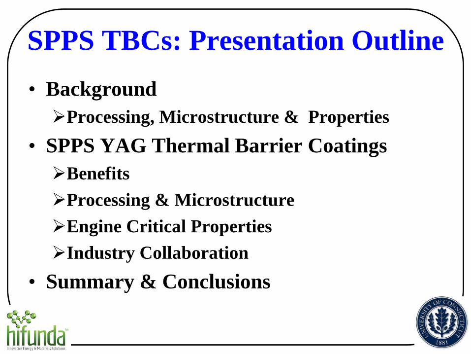
Liquid reservoir
Plasma gun Droplets Coating Substrate
Temperature control unit
Solution Precursor Plasma Spray (SPPS) Process
A B
Liquid injector
Solution Precursors
• A, B or A+B
• Multiple composition

Solution Precursor Plasma Spray: Unique Microstructural Features
100 μm
1 μm
Through-thickness vertical cracks
Varied nano/micro-scale porosity: 0~40%
Splat diameter < 2 μm Splat thickness < 1 μm Splat area is 1/2500 of that in APS TBCs
Layered porosity: inter-pass boundaries.
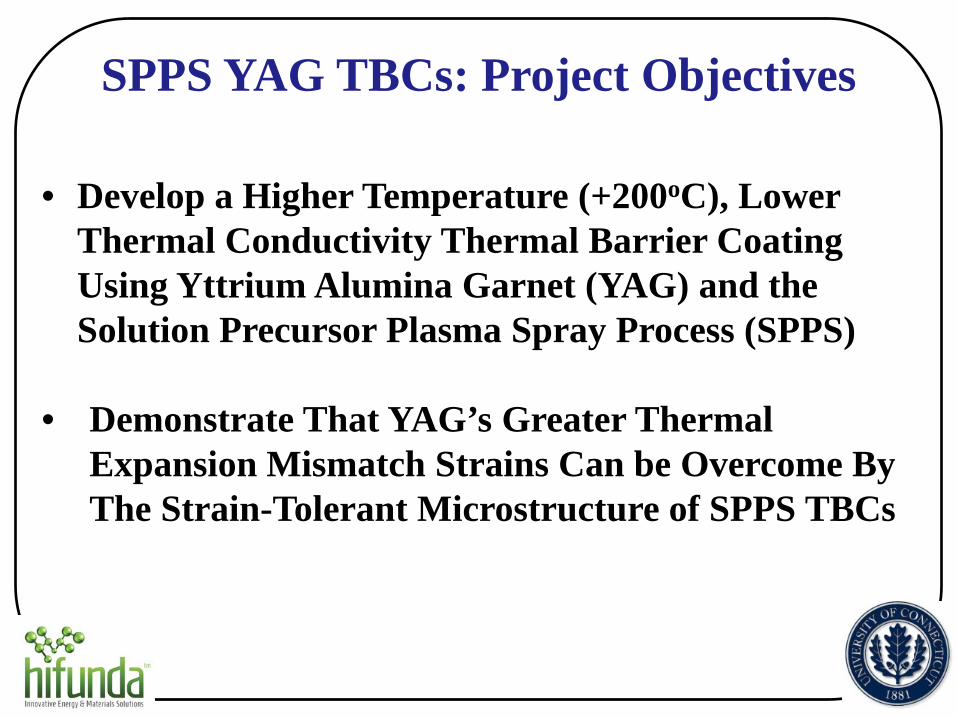
SPPS YAG TBCs: Project Objectives
• Develop a Higher Temperature (+200oC), Lower Thermal Conductivity Thermal Barrier Coating Using Yttrium Alumina Garnet (YAG) and the Solution Precursor Plasma Spray Process (SPPS)
• Demonstrate That YAG’s Greater Thermal Expansion Mismatch Strains Can be Overcome By The Strain-Tolerant Microstructure of SPPS TBCs
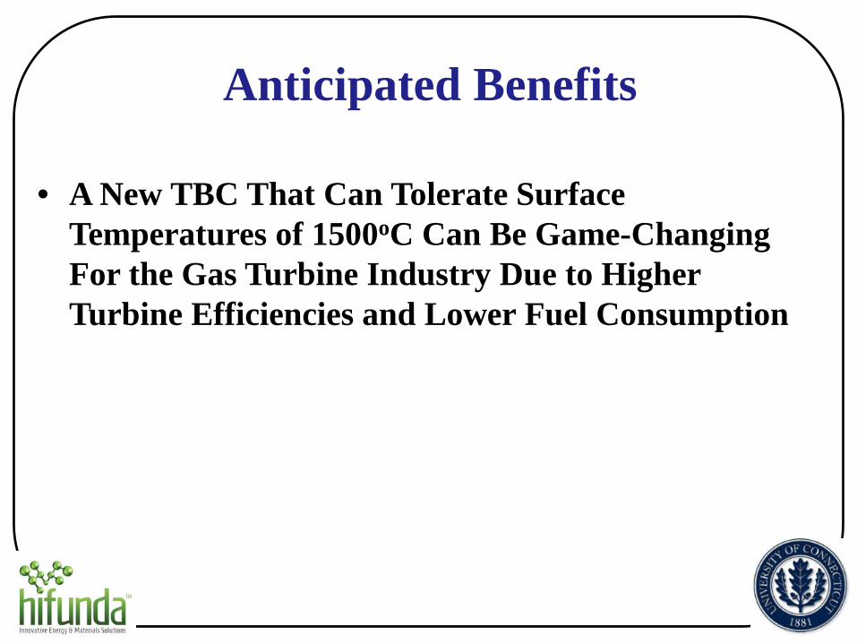
Anticipated Benefits • A New TBC That Can Tolerate Surface
Temperatures of 1500oC Can Be Game-Changing For the Gas Turbine Industry Due to Higher Turbine Efficiencies and Lower Fuel Consumption
Processing & Microstructure
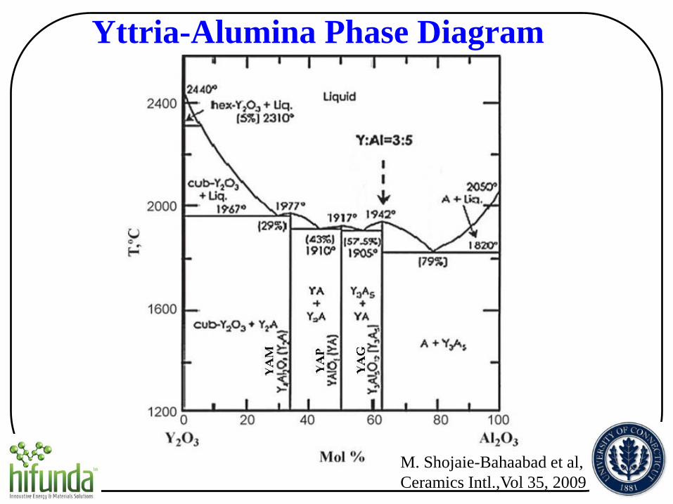
Yttria-Alumina Phase Diagram
M. Shojaie-Bahaabad et al, Ceramics Intl.,Vol 35, 2009
0
10000
20000
30000
40000
50000
60000
70000
80000
20 25 30 35 40 45 50 55 60 65 70
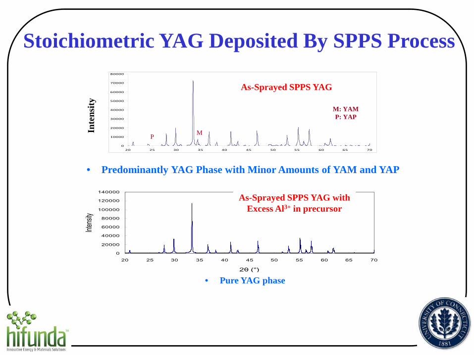
M: YAM P: YAP
M P
As-Sprayed SPPS YAG
0
20000
40000
60000
80000
100000
120000
140000
20 25 30 35 40 45 50 55 60 65 70
2θ (°)
Intensi
ty
As-Sprayed SPPS YAG with Excess Al3+ in precursor
• Predominantly YAG Phase with Minor Amounts of YAM and YAP
• Pure YAG phase
Stoichiometric YAG Deposited By SPPS Process
Inte
nsity
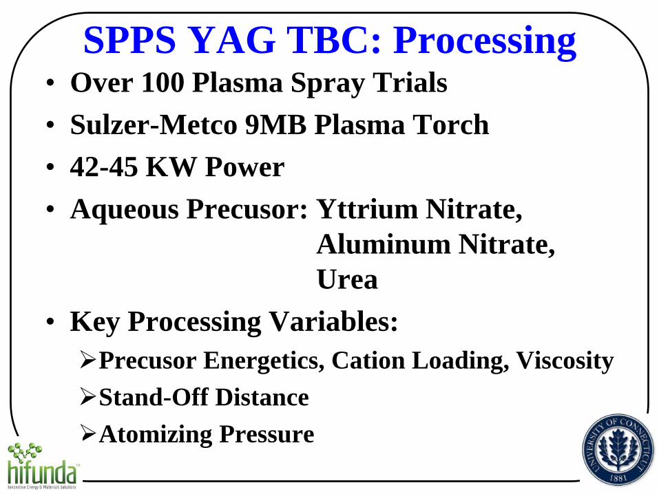
SPPS YAG TBC: Processing • Over 100 Plasma Spray Trials • Sulzer-Metco 9MB Plasma Torch • 42-45 KW Power • Aqueous Precusor: Yttrium Nitrate,
Aluminum Nitrate, Urea
• Key Processing Variables: Precusor Energetics, Cation Loading, Viscosity Stand-Off Distance Atomizing Pressure
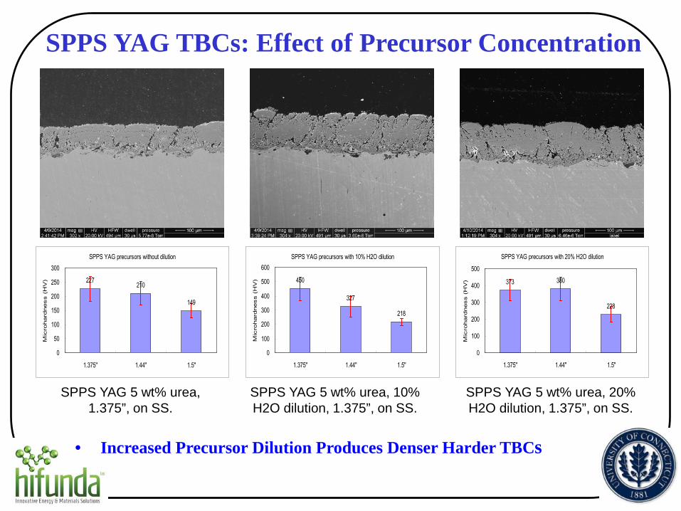
SPPS YAG TBCs: Effect of Precursor Concentration
SPPS YAG 5 wt% urea, 1.375”, on SS.
SPPS YAG 5 wt% urea, 10% H2O dilution, 1.375”, on SS.
SPPS YAG 5 wt% urea, 20% H2O dilution, 1.375”, on SS.
SPPS YAG precursors without dilution
227 210
149
0
50
100
150
200
250
300
1.375" 1.44" 1.5"
Mic
rohard
ness (
HV
)
SPPS YAG precursors with 10% H2O dilution
450
327
218
0
100
200
300
400
500
600
1.375" 1.44" 1.5"
Mic
rohard
ness (
HV
)
SPPS YAG precursors with 20% H2O dilution
373 380
228
0
100
200
300
400
500
1.375" 1.44" 1.5"
Mic
rohard
ness (
HV
)
• Increased Precursor Dilution Produces Denser Harder TBCs
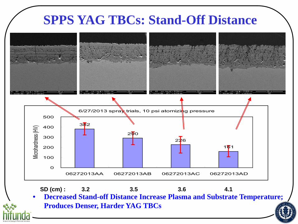
SD (cm) : 3.2 3.5 3.6 4.1
6/27/2013 spray trials, 10 psi atomizing pressure
382
290226
161
0
100
200
300
400
500
06272013AA 06272013AB 06272013AC 06272013AD
Microh
ardnes
s (HV)
SPPS YAG TBCs: Stand-Off Distance
• Decreased Stand-off Distance Increase Plasma and Substrate Temperature; Produces Denser, Harder YAG TBCs
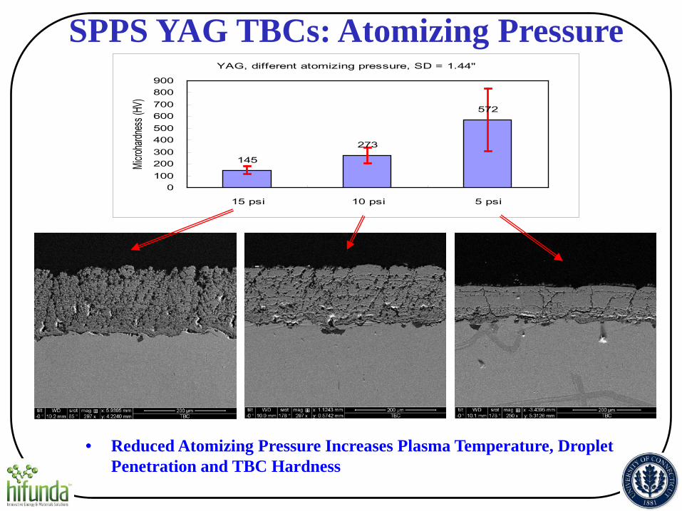
YAG, different atomizing pressure, SD = 1.44"
145
273
572
0100200300400500600700800900
15 psi 10 psi 5 psi
Microh
ardnes
s (HV
)
SPPS YAG TBCs: Atomizing Pressure
• Reduced Atomizing Pressure Increases Plasma Temperature, Droplet Penetration and TBC Hardness
Engine-Critical Properties

SPPS YAG TBCs: Standard Microstructure --Used for Engine-Critical Properties Tests--
SPPS YAG
APS YSZ
Bond Coat
Superalloy
• Vickers Hardness: 200-400 • Porosity: 15-20%

SPPS YAG 1600ºC 100h
0
5000
10000
15000
20000
20 30 40 50 60 702θ (º)
Intensit
y
SPPS YAG TBCs: Phase Stability
0
10000
20000
30000
40000
50000
60000
70000
80000
20 25 30 35 40 45 50 55 60 65 70
• SPPS YAG TBCs Are Phase Stable To At Least 1600oC
M: YAM P: YAP M
P
SPPS YAG 1500°C 100h
0
10000
20000
30000
40000
50000
60000
70000
80000
90000
20 25 30 35 40 45 50 55 60 65 70
2 Theta (°C)
Intensit
y
M: YAM P: YAP
M P
1500ºC 100 hr
As-sprayed SPPS YAG
M P
1600ºC 100 hr M: YAM P: YAP
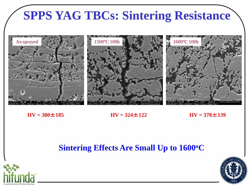
As-sprayed 1500ºC 100h 1600ºC 100h
SPPS YAG TBCs: Sintering Resistance
HV = 324±122 HV = 380±185 HV = 378±139
Sintering Effects Are Small Up to 1600oC
0
10
20
30
40
50
60
70
80
1100 1150 1200 1250 1300 1350 1400 1450 1500 1550
Perc
ent I
ncre
ase
in th
erm
al c
ondu
ctiv
ity
Sintering Temperature ˚C
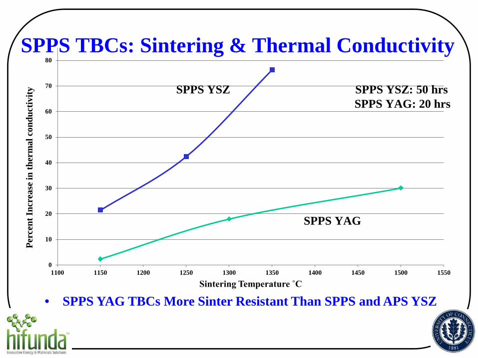
SPPS YSZ: 50 hrs SPPS YAG: 20 hrs
SPPS TBCs: Sintering & Thermal Conductivity
SPPS YSZ
SPPS YAG
• SPPS YAG TBCs More Sinter Resistant Than SPPS and APS YSZ
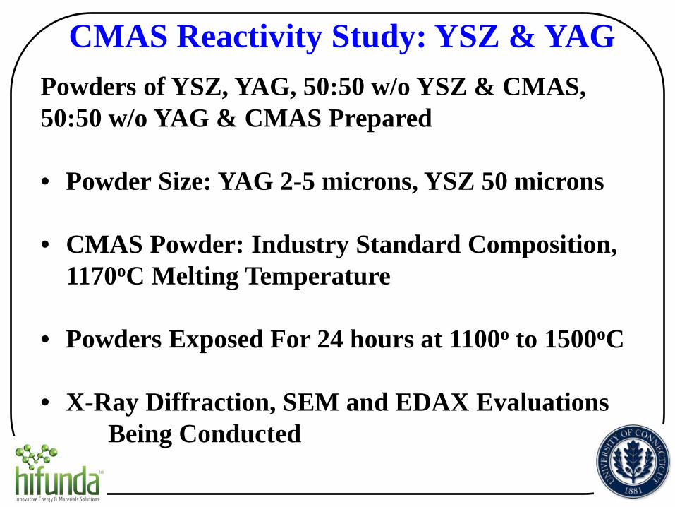
CMAS Reactivity Study: YSZ & YAG Powders of YSZ, YAG, 50:50 w/o YSZ & CMAS, 50:50 w/o YAG & CMAS Prepared • Powder Size: YAG 2-5 microns, YSZ 50 microns
• CMAS Powder: Industry Standard Composition,
1170oC Melting Temperature • Powders Exposed For 24 hours at 1100o to 1500oC • X-Ray Diffraction, SEM and EDAX Evaluations
Being Conducted
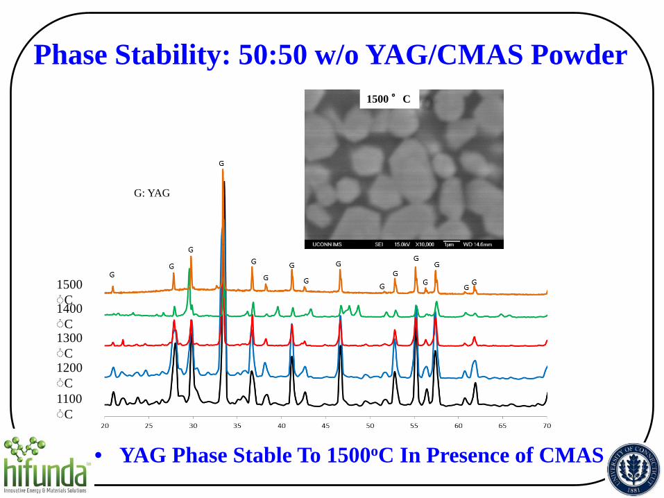
G: YAG
1500 ◌֯C 1400 ◌֯C 1300 ◌֯C 1200 ◌֯C 1100 ◌֯C
1500 °C
Phase Stability: 50:50 w/o YAG/CMAS Powder
• YAG Phase Stable To 1500oC In Presence of CMAS

SPPS YAG TBCs: Thermal Cycle Life vs Hardness
MAX
• SPPS Strain-Tolerant Microstructure Overcomes Higher Thermal Expansion Mismatch Stresses
MIN
AVERAGE
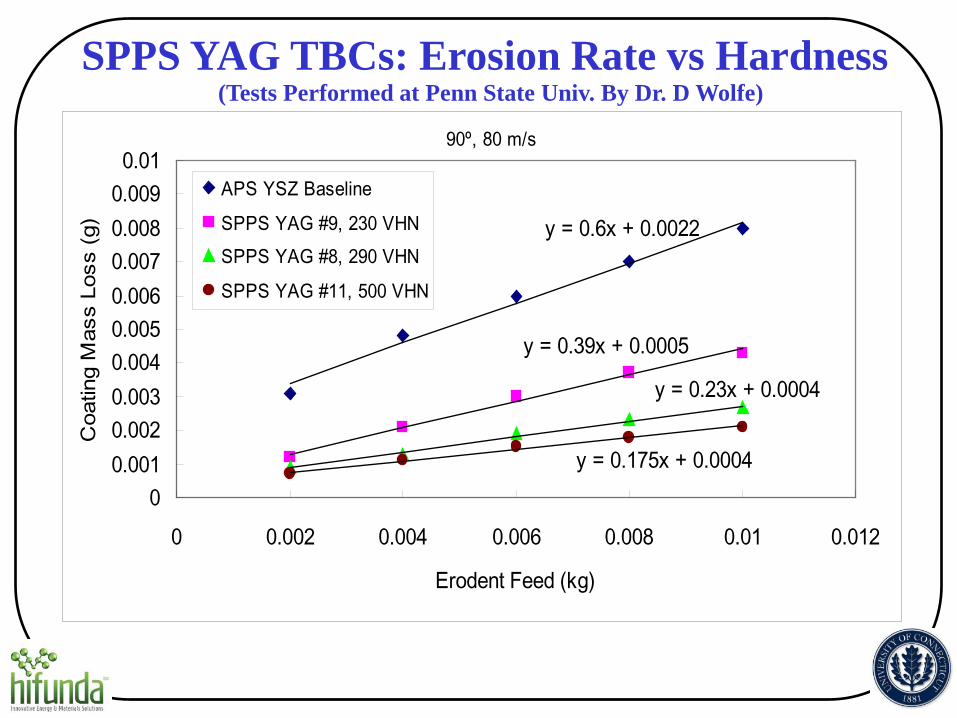
SPPS YAG TBCs: Erosion Rate vs Hardness (Tests Performed at Penn State Univ. By Dr. D Wolfe)
90º, 80 m/s
y = 0.6x + 0.0022
y = 0.39x + 0.0005
y = 0.23x + 0.0004
y = 0.175x + 0.00040
0.0010.0020.0030.0040.0050.0060.0070.0080.0090.01
0 0.002 0.004 0.006 0.008 0.01 0.012
Erodent Feed (kg)
Coa
ting
Mas
s Lo
ss (g
)
APS YSZ Baseline
SPPS YAG #9, 230 VHNSPPS YAG #8, 290 VHN
SPPS YAG #11, 500 VHN

90º, 80 m/s
0.00.10.20.30.40.50.60.70.80.91.0
APS YSZ Baseline SPPS YAG, #9, 230VHN
SPPS YAG, #8, 290VHN
SPPS YAG, #11, 500VHN
Coa
ting
Loss
Rat
e (m
m/k
g)
YSZ
YAG
hardness
SPPS YAG TBCs: Erosion Rate vs Hardness (Tests Performed at Penn State Univ. By Dr. D Wolfe)
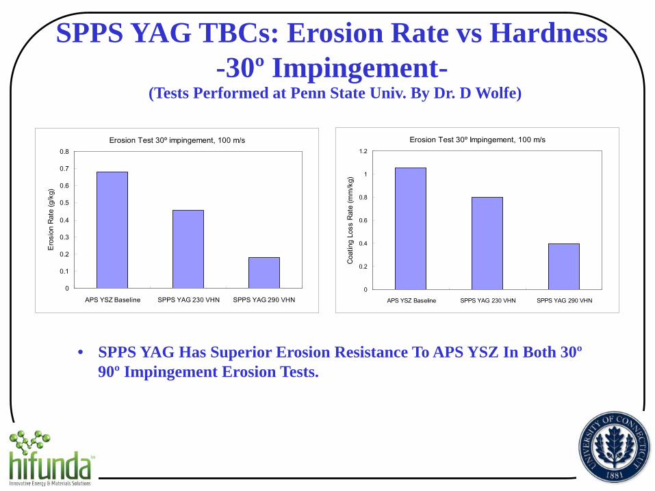
SPPS YAG TBCs: Erosion Rate vs Hardness -30º Impingement-
(Tests Performed at Penn State Univ. By Dr. D Wolfe)
• SPPS YAG Has Superior Erosion Resistance To APS YSZ In Both 30º 90º Impingement Erosion Tests.
Erosion Test 30º impingement, 100 m/s
0
0.1
0.2
0.3
0.4
0.5
0.6
0.7
0.8
APS YSZ Baseline SPPS YAG 230 VHN SPPS YAG 290 VHN
Eros
ion
Rate
(g/k
g)
Erosion Test 30º Impingement, 100 m/s
0
0.2
0.4
0.6
0.8
1
1.2
APS YSZ Baseline SPPS YAG 230 VHN SPPS YAG 290 VHN
Coat
ing
Loss
Rat
e (m
m/k
g)
0
0.2
0.4
0.6
0.8
1
1.2
1.4
1.6
1.8
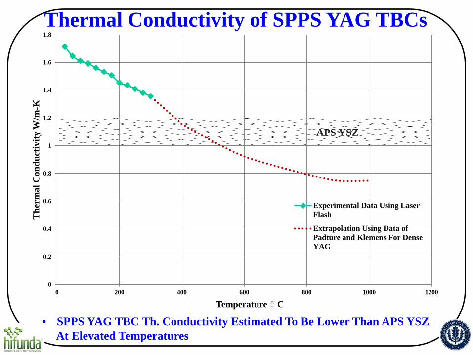
0 200 400 600 800 1000 1200
The
rmal
Con
duct
ivity
W/m
-K
Temperature ◌֯ C
Experimental Data Using LaserFlash
Extrapolation Using Data ofPadture and Klemens For DenseYAG
Thermal Conductivity of SPPS YAG TBCs
• SPPS YAG TBC Th. Conductivity Estimated To Be Lower Than APS YSZ At Elevated Temperatures
APS YSZ

HV= 324±60
SPPS YAG TBCs with IPBs
• Further Reductions in Thermal Conductivity Possible With IPBs & Small Compositional Modifications
Industry Partners
Engine Manufacturers • Solar Turbines • Siemens Energy • Pratt & Whitney
TBC Coating/Equipment Manufacturers • Praxair • Progressive Surface

Industry Partner Coordination
• Solar and Siemens Provided Baseline and Bond Coated Superalloy Specimens Used In Program
• Solar and Siemens Supplied Specimens For SPPS YAG TBC Coating For Their Internal Evaluations
• Technology Transfer Initiated With Praxair & Progressive Engineering Teams Visiting UConn For Full-Day Briefings
• Praxair & Progressive Will Demonstrate Production Process & Economics For SPPS YAG TBCs

Solar Turbines Demonstration Component --Fuel Nozzle Igniter--
• Coordination Meeting Held with Praxair, Solar & UConn, 8-11-14

Summary & Conclusions-I • SPPS YAG TBCs Show Potential For >1500oC
Operation Based On Phase Stability, Sinter and CMAS Resistance
• This Represents A >200oC Advantage Over APS YSZ • Durability of SPPS YAG TBCs Shown To Be Equal
Or Greater Than APS YSZ In Thermal Cycle and Erosion Tests
• Initial Measurements Indicate SPPS YAG TBC Thermal Conductivity of 0.7 Watt/moK at 1000oC (40% reduction compared to APS YSZ)
Summary & Conclusions-II • Engine Manufacturers Continue To Show Strong
Interest In SPPS YAG TBCs; Will Conduct In-House Testing
• Technology Transfer Being Conducted With TBC Coating Suppliers; They Will Conduct Demonstration Trials and Provide Process Economics
• SPPS YAG Continues to Show Strong Promise As Higher Temperature, Sinter-Resistant, Durable TBC
Acknowledgements
• Patcharin Burke, DOE Program Manager, DOE STTR Phase I & II Programs on SPPS YAG TBCs • Our Industrial Partners: Solar Turbines, Siemens
Energy, Pratt & Whitney, Praxair and Progressive Surface