Ultra-dense WDM-PON 6.25 GHz spaced 8x1 Gb/s … · spaced 8x1 Gb/s based on a simplified...
8
Ultra-dense WDM-PON 6.25 GHz spaced 8x1 Gb/s based on a simplified coherent-detection scheme M. Presi, 1,∗ R. Corsini, 1 M. Artiglia, 1 and E. Ciaramella 1 1 Scuola Superiore Sant’Anna, TeCIP Institute, via G. Moruzzi, 1 - 56124 - Pisa - Italy ∗ [email protected] Abstract: We demonstrate experimentally a novel type of coherent low cost Gigabit-to-the-User Ultra-Dense-Wavelength Division Multiplexing (UD-WDM) PON, featuring 6.25 GHz channel spacing and long reach. Polarization-independent coherent detection is achieved by exploiting a novel scheme which requires only a 3 × 3 coupler, three photodiodes, basic analogue processing and a common DFB as local oscillator (LO). This avoids the conventional polarization diversity approach. The DFB LO is free running, i.e. not locked in frequency, and is tuned to detect any of the eight channels by simply changing its temperature in a range of 2 ° C. We achieve 70 km long-reach transmission plus 30 dB attenuation, for a total of > 45 dB optical distribution network loss. This indicates that this solution could be effectively exploited to overlay existing PON infrastructures by UD-WDM. © 2015 Optical Society of America OCIS codes: (060.2330) Fiber optics communications; (060.1660) Coherent communications. References and links 1. S. Narikawa, H. Sanjoh, N. Sakurai, K. Kumozaki, and T. Imai, “Coherent wdm-pon using directly modulated local laser for simple heterodyne transceiver,” ECOC 2005, paper Paper We3.3.2. 2. H. Rohde, S. Smolorz, E. Gottwald, and K. Kloppe, “Next generation optical access: 1 Gbit/s for everyone,” ECOC 2009, Paper 10.5.5. 3. D. Lavery, R. Maher, D. S. Millar, B. C. Thomsen, P. Bayvel, and S. J. Savory, “Digital coherent receivers for long-reach optical access networks,” J. Lightwave Technol. 31, 609–620 (2013). 4. H. Rohde, S. Smolorz, S. Wey, and E. Gottwald, “Coherent optical access networks,” OFC/NFOEC 2011, paper OTuB1. 5. H. Rohde, E. Gottwald, S. Rosner, E. Weis, P. Wagner, Y. Babenko, D. Fritzsche, andH. Chaouch, “Trials of a coherent UDWDM PON over field-deployed fiber: Real-time LTE backhauling, legacy and 100G coexistence,” J. Lightwave Technol. 33, 1644–1649 (2015). 6. J. Prat, M. Angelou, C. Kazmierski, R. Pous, M. Presi, A. Rafel, G. Vall-llosera, I. Tomkos, and E. Ciaramella, “Towards ultra-dense wavelength-to-the-user: the approach of the COCONUT project,” in “Transparent Optical Networks (ICTON), 2013 15th International Conference on,” (IEEE, 2013), paper Tu.C3.2. 7. L. G. Kazovsky, P. Meissner, and E. Patzak, “ASK multiport optical homodyne receivers,” J. Lightwave Technol. 5, 770–791 (1987). 8. M. Presi, F. Bottoni, R. Corsini, G. Cossu, and E. Ciaramella, “All DFB-based coherent udwdm pon with 6.25 GHz spacing and a > 40 dB power budget,” IEEE Photon. Technol. Lett. 26, 107–110 (2013). 9. E. Ciaramella, “Polarization-independent receivers for low-cost coherent OOK systems,” IEEE Photon. Technol. Lett. 26, 548–551 (2014). 10. M. Presi, R. Corsini, and E. Ciaramella, “Experimental demonstration of a novel polarization-independent co- herent receiver for PONs,” OFC 2014 pp. W4G–3. 11. C. Xie, P. J. Winzer, G. Raybon, A. H. Gnauck, B. Zhu, T. Geisler, and B. Edvold, “Colorless coherent receiver using 3x3 coupler hybrids and single-ended detection,” Opt. Express 20, 1164–1171 (2012). #237380 Received 8 May 2015; revised 4 Jul 2015; accepted 7 Jul 2015; published 20 Aug 2015 (C) 2015 OSA 24 Aug 2015 | Vol. 23, No. 17 | DOI:10.1364/OE.23.022706 | OPTICS EXPRESS 22706
Transcript of Ultra-dense WDM-PON 6.25 GHz spaced 8x1 Gb/s … · spaced 8x1 Gb/s based on a simplified...

Ultra-dense WDM-PON 6.25 GHzspaced 8x1 Gb/s based on a simplified
coherent-detection scheme
M. Presi,1,∗ R. Corsini,1 M. Artiglia,1 and E. Ciaramella1
1Scuola Superiore Sant’Anna, TeCIP Institute, via G. Moruzzi, 1 - 56124 - Pisa - Italy∗[email protected]
Abstract: We demonstrate experimentally a novel type of coherent lowcost Gigabit-to-the-User Ultra-Dense-Wavelength Division Multiplexing(UD-WDM) PON, featuring 6.25 GHz channel spacing and long reach.Polarization-independent coherent detection is achieved by exploiting anovel scheme which requires only a 3×3 coupler, three photodiodes, basicanalogue processing and a common DFB as local oscillator (LO). Thisavoids the conventional polarization diversity approach. The DFB LO isfree running, i.e. not locked in frequency, and is tuned to detect any of theeight channels by simply changing its temperature in a range of 2° C. Weachieve 70 km long-reach transmission plus 30 dB attenuation, for a total of> 45 dB optical distribution network loss. This indicates that this solutioncould be effectively exploited to overlay existing PON infrastructures byUD-WDM.
© 2015 Optical Society of AmericaOCIS codes: (060.2330) Fiber optics communications; (060.1660) Coherent communications.
References and links1. S. Narikawa, H. Sanjoh, N. Sakurai, K. Kumozaki, and T. Imai, “Coherent wdm-pon using directly modulated
local laser for simple heterodyne transceiver,” ECOC 2005, paper Paper We3.3.2.2. H. Rohde, S. Smolorz, E. Gottwald, and K. Kloppe, “Next generation optical access: 1 Gbit/s for everyone,”
ECOC 2009, Paper 10.5.5.3. D. Lavery, R. Maher, D. S. Millar, B. C. Thomsen, P. Bayvel, and S. J. Savory, “Digital coherent receivers for
long-reach optical access networks,” J. Lightwave Technol. 31, 609–620 (2013).4. H. Rohde, S. Smolorz, S. Wey, and E. Gottwald, “Coherent optical access networks,” OFC/NFOEC 2011, paper
OTuB1.5. H. Rohde, E. Gottwald, S. Rosner, E. Weis, P. Wagner, Y. Babenko, D. Fritzsche, and H. Chaouch, “Trials of a
coherent UDWDM PON over field-deployed fiber: Real-time LTE backhauling, legacy and 100G coexistence,”J. Lightwave Technol. 33, 1644–1649 (2015).
6. J. Prat, M. Angelou, C. Kazmierski, R. Pous, M. Presi, A. Rafel, G. Vall-llosera, I. Tomkos, and E. Ciaramella,“Towards ultra-dense wavelength-to-the-user: the approach of the COCONUT project,” in “Transparent OpticalNetworks (ICTON), 2013 15th International Conference on,” (IEEE, 2013), paper Tu.C3.2.
7. L. G. Kazovsky, P. Meissner, and E. Patzak, “ASK multiport optical homodyne receivers,” J. Lightwave Technol.5, 770–791 (1987).
8. M. Presi, F. Bottoni, R. Corsini, G. Cossu, and E. Ciaramella, “All DFB-based coherent udwdm pon with 6.25GHz spacing and a > 40 dB power budget,” IEEE Photon. Technol. Lett. 26, 107–110 (2013).
9. E. Ciaramella, “Polarization-independent receivers for low-cost coherent OOK systems,” IEEE Photon. Technol.Lett. 26, 548–551 (2014).
10. M. Presi, R. Corsini, and E. Ciaramella, “Experimental demonstration of a novel polarization-independent co-herent receiver for PONs,” OFC 2014 pp. W4G–3.
11. C. Xie, P. J. Winzer, G. Raybon, A. H. Gnauck, B. Zhu, T. Geisler, and B. Edvold, “Colorless coherent receiverusing 3x3 coupler hybrids and single-ended detection,” Opt. Express 20, 1164–1171 (2012).
#237380 Received 8 May 2015; revised 4 Jul 2015; accepted 7 Jul 2015; published 20 Aug 2015 (C) 2015 OSA 24 Aug 2015 | Vol. 23, No. 17 | DOI:10.1364/OE.23.022706 | OPTICS EXPRESS 22706

1. Introduction
Optical coherent transmission systems are expected to be soon introduced also in access net-works, namely wavelength division multiplexing passive optical networks (WDM-PON) [1–4].However, many of the proposed approaches are based on similar system solutions as for corenetworks, i.e. expensive optical and/or electronic devices (including high-resolution DAC basedtransmitters, ADCs and advanced digital signal processing [5]). In this work, we tackle this keyissue and we focus on UDWDM-PON by means of coherent detection, realized by avoidingexpensive narrow line-width lasers and digital signal processing [6]. We previously demon-strated that a 3× 3 phase diversity receiver [7], realized with common DFBs and simple ana-log electrical processing, works effectively with Gigabit class intensity modulated signals inUDWDM-PON [8].
Furthermore, the receiver had very low sensitivity ( −48 dBm) and required only a coarsecontrol of the local oscillator, whose optical frequency could be detuned up to 1 GHz fromthe signal carrier frequency. Those two features made this scheme very attractive for deploy-ment over splitter-based networks, where loss is high and devices with limited cost shouldbe used [6]. However, this solution was still polarization-dependent. Recently a scheme forextending effectively this approach to a polarization-independent (PI) configuration was pre-sented theoretically [9]: considering the previous phase-diversity receiver, with a symmetric3×3 coupler, polarization-independent (PI) operation can be obtained if the incoming signal issplit and injected into two arms of the coupler, , provided that the frequency detuning betweenthe LO and the signal carrier is high enough (around 70% of the bitrate [10]). We preliminaryassessed this receiver experimentally in single-channel operation [10], confirming that the PIimplementation adds a negligible power penalty.
Here we extend this concept and prove it in more realistic conditions, that is in the 6.25 GHzUD-WDM grid. Given that the PI receiver is operated in intradyne regime the resilience toadjacent crosstalk is reduced as it will be explained later. Therefore its operation over a smallgrid is not trivial and should be demonstrated experimentally. To this aim, we realize a schemethat is compatible with the evolution scenario represented in Fig. 1 [6]. At the OLT, groups of8 UD-WDM channels with 6.25 GHz spacing are multiplexed by cascading 8:1 couplers and acommon AWG (with 50 GHz 3 dB bandwidth). At the ONU, a wavelength pre-selected laserallows selecting any of the eight UD-WDM channels in a given wavelength group. We note thatthis scheme allows co-existence with legacy networks (e.g. the G-PON) operating on differentwavelength bands, without dedicated colored optical filters in the Optical Distribution Network(ODN) which is today composed only of power splitters.
TRX
EDFA
ODN
COCONUT - OLT
ONU
WDM-MUX
8x1TRX
TRX 8x1
TRX ONUG-ONU
G-PON - OLT
G-ONU
G-ONU
ONU
ONU
ONU
ONU
ONU
ONU
ONU
ONU
ONU
Short ReachLow Power Budget
Extended ReachHigh Power Budget
Fig. 1. Scheme and wavelength allocation plan of the considered UD-WDM network. TRX:Transceiver; EDFA Erbium Doped Fiber Amplifier; G-ONU: G-PON Optical NetworkUnit.
#237380 Received 8 May 2015; revised 4 Jul 2015; accepted 7 Jul 2015; published 20 Aug 2015 (C) 2015 OSA 24 Aug 2015 | Vol. 23, No. 17 | DOI:10.1364/OE.23.022706 | OPTICS EXPRESS 22707

70 km SMF
TL
TL
TLMZM
PS VOAEDFA
A/D+
Processing
+3 dBm/chODN
-15 dB
-30 dB
TL
TL
TL
MZMDFB-1
PPG-1
PPG-2
TLTL
OLT
90°
ONU
DFB-23x3 PM
PBS
GOF
LO
RX Bandwidth
Adj. Channelleak
Fig. 2. Experimental setup. TL: Tunable Laser; DFB-1 and DFB-2: Distributed FeedBacklasers; MZM: Mach-Zehnder Modulator; PPG :Pulse Pattern Generator; GOF: GaussianOptical Filter; EDFA: Erbium Doped Fiber Amplifier; PS: Polarization Scrambler; SMF:G-652 Single Mode Fiber; VOA: Variable Optical Attenuator; PBS: Polarization BeamSplitter; 3x3 PM: 3x3 Polarization Maintaining coupler; A/D: Analog-to-Digital Converter.Inset shows the relative position of the local oscillator and the selected WDM channel.
2. Experiments
The experimental setup that emulates the scenario described in Fig. 1, is illustrated in Fig. 2.At the OLT (optical line terminal), 8 CW lasers are coupled together by a network of opticalcouplers. The 8 λ are modulated in two groups of four (odd and even channels) by meansof two Mach-Zehnder (MZ) intensity modulators. The MZs were driven by two independentPRBS sequences with different lengths (27 − 1 and 215 − 1) so that adjacent channels carryuncorrelated data. The lasers (one DFB having 10 MHz linewidth and 7 tunable lasers actingas dummy channels) are set at the frequency spacing of 6.25 GHz around 1557 nm. In thisexperiment, no frequency control is implemented, so that the individual emission frequencywanders in a range of ±100 MHz in respect to the nominal grid (i.e. the laser are operated in aset-and-forget mode). After the modulation stage odd and even channels are coupled togetherwith orthogonal polarization states: in this way, the 8 channels are polarization interleaved,thus minimizing non-linear interactions among adjacent channels. This particular polarizationarrangement might be useful only at the OLT side to increase the launch power of the down-stream channels. The upstream signals interact along the feeder fiber after a network of powersplitting stages. Therefore they are coupled into the feeder power with an optical power which iswell below the threshold for non-linear interactions: thus, no special control of the polarizationof the upstream channels is required.
The UDWDM signals are then sent into a 50 GHz Gaussian filter emulating an usual WDMmultiplexer with 100 GHz channel spacing and 50 GHz bandwidth. After that, an EDFA recov-ers the previous losses and then a variable optical attenuator (VOA) is used to vary the launchpower per channel (thus resulting into values ≤ 3.5 dBm/channel). A polarization scrambler(0.5 dB insertion loss, changing randomly the SoP of the channels at a frequency of 6 kHz)is also added at the ODN input to test the behavior of the polarization independent receiverin a UDWDM environment. The signals are then launched into the ODN, made of a feederfiber and optical attenuators, which emulate the losses due to the passive power splitter(s). Thefeeder fiber is made of two spools of G.652 single mode fibers, with a total length of 70 kmand a total insertion loss of about 17 dB. At the ONU, the receiver is realized according tothe second scheme presented in [9]. Here, in order to obtain stable operation, we realize thereceiver choosing all the pigtailed components made all with polarization-maintaining fibers(PMFs): the incoming signal is first sent through a Polarization Beam Splitter (PBS), whose
#237380 Received 8 May 2015; revised 4 Jul 2015; accepted 7 Jul 2015; published 20 Aug 2015 (C) 2015 OSA 24 Aug 2015 | Vol. 23, No. 17 | DOI:10.1364/OE.23.022706 | OPTICS EXPRESS 22708

PMF outputs are connected to 2 ports of a polarization maintaining 3×3 optical coupler. Oneof the PBS outputs is rotated by 90°, so that both the X and Y polarization components en-ter the slow axes of the 3× 3 coupler (see Fig. 2). DFB-2, used as the local oscillator (LO)is connected to the 3 rd coupler port; it is also aligned to the coupler slow axis [9, 10]. Thepolarization rotation is implemented by proper alignment of the connectors at the PBS outputs:one of them has the key aligned to the slow axis, while the other has the key aligned to the fastaxis). This arrangement of the PMFs used in the receiver avoids any dependency on the polar-ization control of the involved signals (in particular on the local oscillator). By doing this thereceiver performance have been also improved significantly: the BER floor that was apparentin the results published in [10] has been removed thanks to this solution. The implementationbased on polarization-maintaining components described above aims only at obtaining a stablesystem to demonstrating a proof-of-concept of the receiver in a WDM scenario. The presentimplementation is of course not cost-effective. In order to obtain cost-effective realizations fordeployment scenarios, other platforms should be investigated such as integrated circuits or sil-ica planar waveguides, as in the case of commercially available 90° hyrid couplers. The 3× 3coupler outputs are detected by three PIN+TIA diodes (2.5 GHz bandwidth), and a Real-TimeOscilloscope is used for A/D conversion (40 GS/s, 8 bit resolution) and processing [10]. Asin [10], the processing consists in squaring and summing the differential output currents ofthe three photodiodes. By doing this, the direct-detection terms due to the WDM channels areminiimzed [11]. Once properly connected, the PMF components provide stable operation, thusin this configuration, the receiver is fully polarization independent and no manual polarizationoptimization/adjustment (e.g. usual polarization controller) is required inside the receiver. Thereceiver is used to detect each of the eight UD-WDM channels by tuning the LO. This is ac-complished by varying the DFB operating temperature and bias current, for coarse and fineadjustment, respectively: in our case, the maximum temperature and current variations to selectall 8 channels were of ±2° C and ±4 mA around the nominal values ( 20° C and 60 mA).
3. Receiver characterization
The LO was kept to an intradyne detuning of 900 MHz (±100 MHz). The optimal detun-ing value has been predicted theoretically in [9]. In Fig. 3 we report the receiver tolerance tofluctuations of the signal-LO detuning as it is measured experimentally. The measurement isperformed by keeping a fixed optical power to the receiver. For comparison, Fig. 3 also reportsthe tolerance in the case of single-polarization operation (white squares). The same measure-ment has been performed by using post-detection filters of different bandwidths. As can be seen,while the single polarization receiver is almost insensitive to detuning values up to 1 GHz [7] the
2
3
4
5
60 0.2 0.4 0.6 0.8 1 1.2 1.4 1.6
BER vs. Signal-LO Detuning
933 MHz800 MHz700600Single Pol
-log(
BE
R)
Signal-LO Detuning (GHz)
Rx Filter BW:
1
2
3
4
56
0 2 4 6 8 10
BER History
-log(
BE
R)
Time (minutes)
AVG BER: 1.2e-4
Fig. 3. Left: Tolerance of signal to local oscillator detuning in the proposed polarizationreceiver. for different bandwiths of the post-detection filter. Right: BER history log over 10minutes of the polarization independent receiver.
#237380 Received 8 May 2015; revised 4 Jul 2015; accepted 7 Jul 2015; published 20 Aug 2015 (C) 2015 OSA 24 Aug 2015 | Vol. 23, No. 17 | DOI:10.1364/OE.23.022706 | OPTICS EXPRESS 22709

polarization independent receiver works well in a reduced detuning range (±100 MHz around900 MHz). When the signal-lo frequency detunings is small (< 900 MHz), the interference termbetween the two splitted polarization components is fully in-band to the recovered signal. Onthe other hand, at high frequency detunings (> 900 MHz) the interference terms falls outsidethe signal bandwidth and can be effectively filtered out by the post-detection filter. In symmary,the signal-LO detuning tolerance is bound on one side by the signaling rate and by the photodi-ode bandwidth on the other side. Such a tolerance could be in princinple extended by increasingthe photodiodes bandwidth; however this would limit the minimum channel spacing in case ofWDM operations as discussed briefly in the next section.
As explained in detail in [9], when the input signal is not polarization aligned with one ofthe PBS axis, a interference term appears at a frequency which is twice the signal-LO detuningvalue. This can be clearly seen in Fig. 4 where we report the detected signal as measured atpoint A in the receiver (see Fig. 2), i.e. before low-pass filtering: when the input polarization isaligned along one of the PBS axis, the envelope clearly shows an NRZ signal. On the other hand,when the input signal is linearly polarized at 45° with respect to the polarizer the reconstructedenvelope contains a beating term at a twice the signal-lo detuning frequency [9]. The beatingterm is also clearly visible in the electrical spectrum of the trace, which is also reported in Fig.4. Eye-diagrams of Fig. 4 show the action of the post-detection filter on the envelope recoveredsignal in the case of an input signal having a 45° polarization rotation. As can be seen a933 MHz filter, which is usually employed in 1.25 Gb/s NRZ systems performs a very a goodreshaping. Narrower post detection filters are not effective, as shown in Fig. 3.
The tolerance of 200 MHz on the signal-LO detuning allowed to avoid a fast frequencycontrol on the local oscillator. In a real implementation of the receiver, such detuning might beimplemented by means of a slow and very low bandwidth frequency locking-loop, acting onthe local oscillator laser bias, this avoiding the need of a dedicated fast PLL circuit. In Fig. 3 wealso report the BER fluctuations measured over the time when the receiver detects a signal ofrandom varying polarization. Such a random polarization change is induced by a commercialpolarization scrambler which provides for random polarization changes at a frequency of 6 kHz.
0
0.0005
0.001
0.0015
0.002
0 10 20 30 40 50
Pol XYPol X
Time (ns)
Am
plitu
de (
a.u.
)
-100
-90
-80
-70
-60
-50
0 1 2 3 4 5
Pow
er (
dBm
)
Frequency (GHz)
Interference Term
Pol-XPol XY
(no filter)Pol XY
933 MHz Bessel
Fig. 4. Effect of the post-envelope low pass filter on the interfernce term generated when thereceived signal is not aligned to one of the PBS axis. Top left: detected envelopes when thesignal is polarization aligned to the PBS axis (’PolX’)or with a 45° angle (’PolXY’). Topright: spectrum of the received signal with 45° angle. These traces are recorded at point Ain Fig. 2. Bottom eye diagram shows the received signal before and after low-pass filteringthat suppresses the interference term.
#237380 Received 8 May 2015; revised 4 Jul 2015; accepted 7 Jul 2015; published 20 Aug 2015 (C) 2015 OSA 24 Aug 2015 | Vol. 23, No. 17 | DOI:10.1364/OE.23.022706 | OPTICS EXPRESS 22710
-60
-50
-40
-30
-20
-10
1556.8 1557 1557.2 1557.4 1557.6
WDM Received Spectrum (0 dBm/ch)
Pow
er (
dBm
)
Wavelength (nm)
-60
-50
-40
-30
-20
-10
1556.8 1557 1557.2 1557.4 1557.6
WDM Received Spectrum (3.5 dBm/ch)
Pow
er (
dBm
)
Wavelength (nm)
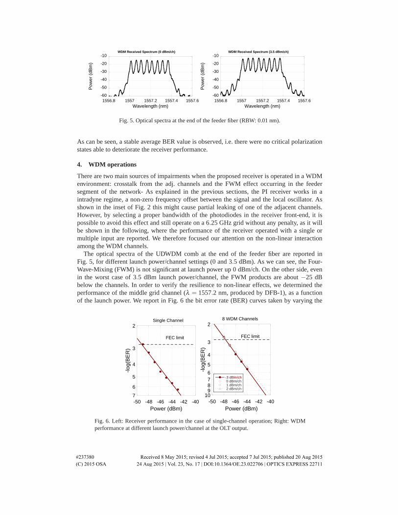
Fig. 5. Optical spectra at the end of the feeder fiber (RBW: 0.01 nm).
As can be seen, a stable average BER value is observed, i.e. there were no critical polarizationstates able to deteriorate the receiver performance.
4. WDM operations
There are two main sources of impairments when the proposed receiver is operated in a WDMenvironment: crosstalk from the adj. channels and the FWM effect occurring in the feedersegment of the network- As explained in the previous sections, the PI receiver works in aintradyne regime, a non-zero frequency offset between the signal and the local oscillator. Asshown in the inset of Fig. 2 this might cause partial leaking of one of the adjacent channels.However, by selecting a proper bandwidth of the photodiodes in the receiver front-end, it ispossible to avoid this effect and still operate on a 6.25 GHz grid without any penalty, as it willbe shown in the following, where the performance of the receiver operated with a single ormultiple input are reported. We therefore focused our attention on the non-linear interactionamong the WDM channels.
The optical spectra of the UDWDM comb at the end of the feeder fiber are reported inFig. 5, for different launch power/channel settings (0 and 3.5 dBm). As we can see, the Four-Wave-Mixing (FWM) is not significant at launch power up 0 dBm/ch. On the other side, evenin the worst case of 3.5 dBm launch power/channel, the FWM products are about −25 dBbelow the channels. In order to verify the resilience to non-linear effects, we determined theperformance of the middle grid channel (λ = 1557.2 nm, produced by DFB-1), as a functionof the launch power. We report in Fig. 6 the bit error rate (BER) curves taken by varying the
2
3
4
5
6
7-50 -48 -46 -44 -42 -40
-log(
BE
R)
Power (dBm)
FEC limit
Single Channel2
3
4
5
6789
10-50 -48 -46 -44 -42 -40
-3 dBm/ch 0 dBm/ch 1 dBm/ch 2 dBm/ch
-log(
BE
R)
Power (dBm)
FEC limit
8 WDM Channels
Fig. 6. Left: Receiver performance in the case of single-channel operation; Right: WDMperformance at different launch power/channel at the OLT output.
#237380 Received 8 May 2015; revised 4 Jul 2015; accepted 7 Jul 2015; published 20 Aug 2015 (C) 2015 OSA 24 Aug 2015 | Vol. 23, No. 17 | DOI:10.1364/OE.23.022706 | OPTICS EXPRESS 22711

40
42
44
46
48
50
-4 -3 -2 -1 0 1 2 3 4
OD
N L
oss
(dB
)
Launch Power/ch (dBm)
Fig. 7. Power budget vs launch power per channel at the ODN.
received power of the middle channel after the transmission line. In the same figure, we report,as reference, the performance of the receiver when only one channel is detected. As can beseen the power penalty measured for different launch power level is very low (< 0.5 dB at aBER of 10−6 ). We note that when the receiver is operated with multiple signals at the input,a power penalty is introduced at the FEC level, which is probably due to a residual of thedirect-detection terms (although we process the differential photocurrents in order to cancel-out the direct-detection terms such a cancellation is not perfect due to mismatch in photodiodesresponsivities and frequency response ). Nevertheless, with a sensitivity of −48 dBm at the FEClevel (BER=1.2x10⁻³), and a launch power of 2 dBm, this indicates a power budget of at least50 dB over a 70 km reach. This result is in-line with what can be achieved by using state-of-the-art, higher-complexity, UDWDM-PON transceivers [5], although the proposed simplifiedapproach pays in terms of spectral efficiency. Further increasing the launch power seems not tobe beneficial in terms of power budget. This is reported in Fig. 7 where we report the measuredODN loss budget as a function of the launch power. As can be seen, when the launch power isincreased to 3.5 dBm, the maximum value achievable with the EDFA used in the experiment,the system ODN loss does not increase. In this measurement, in order to obtain a conservativevalue, the sensitivity of the receiver was fixed at a BER of 10−5.
We then characterize the performance of all the channels. We set the launch power to themaximum value (3.5 dBm/ch) and a fixed attenuation of 30 dB after the transmission line(47 dB total insertion loss). Also in these measurements the local oscillator power was fixedto 0 dBm, which resulted to be the optimal condition value for our receiver. Figure 8 reportsthe measured BER on individual channels, obtained by tuning the LO. As can be seen, all thechannels show a BER between 1.5 ·10−5 and 5 ·10−6, which are well below the FEC threshold.By comparing this result with Fig. 6 we see the availability of at least 2 dB of margin to reach the
2
3
4
567
0 2 4 6 8 10
WDM Performance
-log(
BE
R)
Channel Number
FEC limit
Fig. 8. BER values on each of the 8 channels after propagation along the ODN (Plaunch =3.5 dBm/ch). Inset shows the eye diagrams recorded for each channel.
#237380 Received 8 May 2015; revised 4 Jul 2015; accepted 7 Jul 2015; published 20 Aug 2015 (C) 2015 OSA 24 Aug 2015 | Vol. 23, No. 17 | DOI:10.1364/OE.23.022706 | OPTICS EXPRESS 22712

FEC level. The slight performance difference among the 8 channels is likely due by the non-uniformity of the individual channel power (set with a resolution of 0.5 dB). We also noticethat the performance of the DFB-based channel cannot be distinguished from the TL ones,indicating that the use of a DFB as transmitter as well as LO does not introduce appreciablepenalty. For completeness Fig. 8 also reports the eye- diagrams of all the 8 channels.
5. Conclusions
We presented a simplified polarization-independent coherent receiver suitable for access sys-tems. The receiver avoids the use of polarization diversity but is still very robust against inputpolarization fluctuations. Thanks to an all-fiber implementation the receiver performance isimproved with respect to that previously reported. Although requiring intradyne operation, thereceiver can be used in ultra-dense WDM applications as the characterization in a 8x1.25 Gbit/s(gross-rate) UD-WDM systems with channel density as low as 6.25 GHz clearly shows. All thesystem is based on simple components such as common DFBs used as as a LO, which can selectany of the incoming channels over a 6.25 GHz range (by a thermal tuning of 4°C). High powerbudget is demonstrated (50 dB), which is very promising for future deployment over today ex-isting infrastructures, where high-loss splitters are present. This is particularly significant sinceonly off-the-shelf components are required and all elements of the transmitter/receiver are inprinciple low-cost.
Acknowledgment
This work has been carried out under the framework of EU-funded FP7 project COCONUT(G.A. 318515)
#237380 Received 8 May 2015; revised 4 Jul 2015; accepted 7 Jul 2015; published 20 Aug 2015 (C) 2015 OSA 24 Aug 2015 | Vol. 23, No. 17 | DOI:10.1364/OE.23.022706 | OPTICS EXPRESS 22713