Ultimate™ U39 Freestanding Gas Stove Owners & Installation ...
52
FPI FIREPLACE PRODUCTS INTERNATIONAL LTD. 6988 Venture St., Delta, BC Canada, V4G 1H4 919-482e MODELS: U39-NG10 Natural Gas U39-LP10 Propane 02.19.19 Ultimate™ U39 Freestanding Gas Stove Owners & Installation Manual www.regency-fire.com - Do not store or use gasoline or other flammable vapors and liquids in the vicinity of this or any other appliance. - WHAT TO DO IF YOU SMELL GAS • Do not try to light any appliance. • Do not touch any electrical switch: do not use any phone in your building. Leave the building immediately. • Immediately call your gas supplier from a neighbour's phone. Follow the gas supplier's instructions. • If you cannot reach your gas supplier, call the fire department. Installation and service must be performed by a qualified installer, service agency or the gas supplier. WARNING FIRE OR EXPLOSION HAZARD Failure to follow safety warnings exactly could result in serious injury, death, or property damage. Installer: Please complete the details on the back cover and leave this manual with the homeowner. Homeowner: Please keep these instructions for future reference. Tested by: Certified to/Certifié pour: CSA 2.17-2017 ANSI Z21.88-2017 CSA 2.33-2017
Transcript of Ultimate™ U39 Freestanding Gas Stove Owners & Installation ...

FPI FIREPLACE PRODUCTS INTERNATIONAL LTD. 6988 Venture St., Delta, BC Canada, V4G 1H4919-482e
MODELS: U39-NG10 Natural Gas U39-LP10 Propane
02.19.19
Ultimate™ U39 Freestanding Gas Stove Owners & Installation Manual
www.regency-fire.com
- Do not store or use gasoline or other flammable vapors and liquids in the vicinity of this or any other appliance.
- WHAT TO DO IF YOU SMELL GAS • Do not try to light any appliance. • Do not touch any electrical switch: do not use any phone in your building. Leave the building immediately. • Immediately call your gas supplier from a neighbour's phone. Follow the gas supplier's
instructions. • If you cannot reach your gas supplier, call the fire department. Installation and service must be performed by a qualified installer, service agency or the gas supplier.
WARNINGFIRE OR EXPLOSION HAZARDFailure to follow safety warnings exactly could result in seriousinjury, death, or property damage.
Installer: Please complete the details on the back cover and leave this manual with the homeowner.Homeowner: Please keep these instructions for future reference.
Tested by: Certified to/Certifié pour: CSA 2.17-2017 ANSI Z21.88-2017 CSA 2.33-2017

2 | Regency® U39-10 ULTIMATE™ Direct Vent Freestanding Gas Stove
| 2
REGENCY®
ULTIMATE Direct Vent Freestanding Gas StoveTo the New Owner:
Congratulations! You are the owner of a state-of-the-art ULTIMATE Direct Vent Gas Stove by FPI Fireplace Products International Ltd. The Regency® Gas Series of hand crafted appliances has been designed to provide you with all the warmth and charm of a woodstove, at the flick of a switch. The models U39-NG10, and U39-LP10 of this series has been approved by Warnock Hersey/Intertek for both safety and efficiency. As it also bears our own mark, it promises to provide you with economy, comfort and security for many trouble free years to follow. Please take a moment now to acquaint yourself with these instructions and the many features of your ULTIMATE Direct Vent Freestanding Gas Stove.
U38-39 Video
This appliance may only be installed in an after-market permanently located, manufactured (USA only) or mobile home, where not prohibited by local codes. This appliance is only for use with the type of gas indicated on the rating plate. This appliance is not convertible for use with other gases, unless a certified kit is used.

Regency® U39-10 ULTIMATE™ Direct Vent Freestanding Gas Stove | 3
3| table of contents
Installation Before You Start .............................................................7Important Message ........................................................8Specifications ................................................................8Information For Mobile/Manufactured Homes After First Sale ...............................................................8General Safety Information ............................................9Installation Checklist ......................................................9Clearances To Combustibles .........................................9Manufactured Mobile Home Additional Requirements 10Locating Your Ultimate Gas Stove .............................10Combustion And Ventilation Air ...................................10Louver Installation .......................................................10Safety screen Installation ............................................10Venting Introduction ....................................................10Exterior Vent Terminal Locations .................................114” x 6-5/8” Rigid Pipe Cross Reference Chart .............12Rigid Pipe Venting Systems .........................................14Installation Precautions ...............................................15Rigid Pipe Venting Arrangements ................................15DV Stove Horizontal Vent Kit Installation .....................17Dura-vent Termination Kit ............................................19Converting a Class-A Metal Chimney to a Direct Vent System ......................................................23Gas Connection ...........................................................25High Elevation ..............................................................25Conversion from NG to LP...........................................26Conversion to Lower BTU Rating ................................27Gas Pipe Pressure Testing ..........................................27Aeration Adjustment ....................................................28Log Set Installation ......................................................29Wiring Diagrams .........................................................32
Optional Wall Thermostat ...........................................33DC spark igniter battery install ....................................33Final Check ..................................................................33First Fire ......................................................................33
Operating InstructionsOperating Instructions .................................................34Lighting Procedure ......................................................34Shutdown Procedure ...................................................34First Fire ......................................................................36Automatic Convection Fan Operation ..........................36Normal Operating Sounds of Gas Appliances ...............6
MaintenanceMaintenance Instructions ............................................37General Vent Maintenance ..........................................37Log replacement ..........................................................38Door Gasket ...............................................................38Latch Adjustment .........................................................38Glass Replacement .....................................................38Fan Maintenance .........................................................39DC Sparker battery replacement .................................39Valve replacement .......................................................40
PartsMain Assembly ............................................................41Burner & Log Assembly ...............................................42Door Assembly ............................................................43
WarrantyWarranty ......................................................................44

4 | Regency® U39-10 ULTIMATE™ Direct Vent Freestanding Gas Stove
| 4 dimensions
ALL PICTURES / DIAGRAMS SHOWN THROUGHOUT THIS MANUAL ARE FOR ILLUSTRATION PURPOSES ONLY.ACTUAL PRODUCT MAY VARY DUE TO PRODUCT ENHANCEMENTS.
91316"(250mm)
(108
mm)
41 4"
Regency® U39-10 ULTIMATE™ Direct Vent Freestanding Gas Stove | 5
5| safety decal
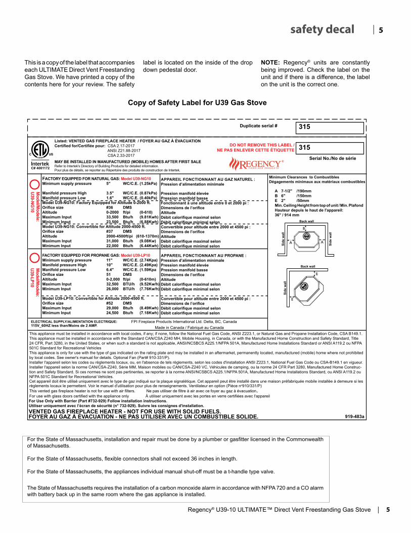
This is a copy of the label that accompanies each ULTIMATE Direct Vent Freestanding Gas Stove. We have printed a copy of the contents here for your review. The safety
label is located on the inside of the drop down pedestal door.
Copy of Safety Label for U39 Gas Stove
NOTE: Regency® units are constantly being improved. Check the label on the unit and if there is a difference, the label on the unit is the correct one.
Minimum Clearances to Combustibles Dégagements minimaux aux matériaux combustibles
315Serial No./No de série
DO NOT REMOVE THIS LABEL /NE PAS ENLEVER CETTE ÉTIQUETTE
919-483a
A 7-1/2" /190mmB 6" /150mmE 2" /50mmMin. Ceiling Height from top of unit / Min. Plafond Hauteur depuis le haut de l'appareil: 36" / 914 mm
Duplicate serial #
Model/M
odele: U39-NG
10M
odel/Modele:
U39-LP10
315
MAY BE INSTALLED IN MANUFACTURED (MOBILE) HOMES AFTER FIRST SALERefer to Intertek's Directory of Building Products for detailed information.Pour plus de détails, se reporter au Répertoire des produits de construction de Intertek.
This appliance must be installed in accordance with local codes, if any; if none, follow the National Fuel Gas Code, ANSI Z223.1, or Natural Gas and Propane Installation Code, CSA B149.1.This appliance must be installed in accordance with the Standard CAN/CSA Z240 MH, Mobile Housing, in Canada, or with the Manufactured Home Construction and Safety Standard, Title 24 CFR, Part 3280, in the United States, or when such a standard is not applicable, ANSI/NCSBCS A225.1/NFPA 501A, Manufactured Home Installations Standard or ANSI A119.2 ou NFPA 501C Standard for Recreational VehiclesThis appliance is only for use with the type of gas indicated on the rating plate and may be installed in an aftermarket, permanently located, manufactured (mobile) home where not prohibited by local codes. See owner's manual for details. Optional Fan (Part# 910-331/P).Installer l'appareil selon les codes ou règlements locaux, ou, en l'absence de tels règlements, selon les codes d'installation ANSI Z223.1, National Fuel Gas Code ou CSA-B149.1 en vigueur.Installer l'appareil selon la norme CAN/CSA-Z240, Série MM, Maison mobiles ou CAN/CSA-Z240 VC, Véhicules de camping, ou la norme 24 CFR Part 3280, Manufactured Home Construc-tion and Safety Standard. Si ces normes ne sont pas pertinentes, se reporter à la norme ANSI/NCSBCS A225.1/NFPA 501A, Manufactured Home Installations Standard, ou ANSI A119.2 ou NFPA 501C Standard for Recreational Vehicles.Cet appareil doit être utilisé uniquement avec le type de gaz indiqué sur la plaque signalétique. Cet appareil peut être installé dans une maison préfabriquée mobile installée à demeure si les règlements locaux le permettent. Voir le manuel d'utilisation pour plus de renseignements. Ventilateur en option (Pièce no910/331/P)This vented gas fireplace heater is not for use with air filters. Ne pas utiliser de filtre à air avec ce foyer au gaz à évacuation. For use with glass doors certified with the appliance only À utiliser uniquement avec les portes en verre certifiées avec l'appareil
VENTED GAS FIREPLACE HEATER - NOT FOR USE WITH SOLID FUELS. FOYER AU GAZ À ÉVACUATION - NE PAS UTILISER AVEC UN COMBUSTIBLE SOLIDE.
Made in Canada / Fabriqué au Canada
Listed: VENTED GAS FIREPLACE HEATER / FOYER AU GAZ À ÉVACUATIONCertified for/Certifiée pour: CSA 2.17-2017 ANSI Z21.88-2017 CSA 2.33-2017
C# 4001172
For Use Only with Barrier (Part #732-929) Follow installation instructions.Utiliser uniquement avec l’écran de sécurité (n° 732-929). Suivre les consignes d'installation.
ELECTRICAL SUPPLY/ALIMENTATION ELECTRIQUE: 115V_60HZ less than/Moins de 2 AMP.
FPI Fireplace Products International Ltd. Delta, BC, Canada
FACTORY EQUIPPED FOR NATURAL GAS: Model U39-NG10Minimum supply pressure 5" WC/C.E. (1.25kPa)
Manifold pressure High 3.5" WC/C.E. (0.87kPa)Manifold pressure Low 1.6" WC/C.E. (0.40kPa)Model U39-NG10: Factory Equipped for Altitude 0-2000 ft.Orifice size #36 DMSAltitude 0-2000 ft/pi (0-610)Maximum Input 33,500 Btu/h (9.81Kwh)Minimum Input 23,500 Btu/h (6.88Kwh)Model U39-NG10: Convertible for Altitude 2000-4500 ft.Orifice size #37 DMSAltitude 2000-4500ft/pi (610-1370m)Maximum Input 31,000 Btu/h (9.08Kw)Minimum Input 22,000 Btu/h (6.44Kwh)
FACTORY EQUIPPED FOR PROPANE GAS: Model U39-LP10Minimum supply pressure 11" WC/C.E. (2.74Kpa)Manifold pressure High 10" WC/C.E. (2.49Kpa)Manifold pressure Low 6.4" WC/C.E. (1.59KpaOrifice size 51 DMSAltitude 0-2,000 ft/pi (0-610m)Maximum Input 32,500 BTU/h (9.52Kw/h)Minimum Input 26,000 BTU/h (7.76Kw/h)
Model U39-LP10: Convertible for Altitude 2000-4500 ft.Orifice size #52 DMSMaximum Input 29,000 Btu/h (8.49Kwh)Minimum Input 24,500 Btu/h (7.18Kwh)
APPAREIL FONCTIONNANT AU GAZ NATUREL :Pression d’alimentation minimale
Pression manifold élevéePression manifold basseFonctionnant à une altitude entre 0 et 2000 pi :Dimensions de l’orificeAltitudeDébit calorifique maximal selonDébit calorifique minimal selonConvertible pour altitude entre 2000 et 4500 pi :Dimensions de l’orificeAltitudeDébit calorifique maximal selonDébit calorifique minimal selon
APPAREIL FONCTIONNANT AU PROPANE :Pression d’alimentation minimalePression manifold élevéePression manifold basseDimensions de l’orifice AltitudeDébit calorifique maximal selonDébit calorifique minimal selon
Convertible pour altitude entre 2000 et 4500 pi :Dimensions de l’orificeDébit calorifique maximal selonDébit calorifique minimal selon
Part #: 919-483aColour: Black on Grey except selected text is in red as per this print.Material: 2 ml silver matt polyester (DPM SMS)Size: 100% Dec. 15/14: Created DecalDec. 03/18 Rev. A - updated standard +data as per R/D*Printer : Continue Serial # series from 918-509 DO NOT RESTART at 0
For the State of Massachusetts, installation and repair must be done by a plumber or gasfitter licensed in the Commonwealth of Massachusetts.
For the State of Massachusetts, flexible connectors shall not exceed 36 inches in length.
For the State of Massachusetts, the appliances individual manual shut-off must be a t-handle type valve.
The State of Massachusetts requires the installation of a carbon monoxide alarm in accordance with NFPA 720 and a CO alarm with battery back up in the same room where the gas appliance is installed.

6 | Regency® U39-10 ULTIMATE™ Direct Vent Freestanding Gas Stove
| 6 requirements
5.08: Modifications to NFPA-54, Chapter 10
(2) Revise 10.8.3 by adding the following additional requirements:
(a) For all side wall horizontally vented gas fueled equipment installed in every dwelling, building or structure used in whole or in part for residential purposes, including those owned or operated by the Commonwealth and where the side wall exhaust vent termination is less than seven (7) feet above finished grade in the area of the venting, including but not limited to decks and porches, the following requirements shall be satisfied:
1. INSTALLATION OF CARBON MONOXIDE DETECTORS. At the time of installation of the side wall horizontal vented gas fueled equipment, the installing plumber or gasfitter shall observe that a hard wired carbon monoxide detector with an alarm and battery back-up is installed on the floor level where the gas equipment is to be installed. In addition, the installing plumber or gasfitter shall observe that a battery operated or hard wired carbon monoxide detector with an alarm is installed on each additional level of the dwelling, building or structure served by the side wall horizontal vented gas fueled equipment. It shall be the responsibility of the property owner to secure the services of qualified licensed professionals for the installation of hard wired carbon monoxide detectors
a. In the event that the side wall horizontally vented gas fueled equipment is installed in a crawl space or an attic, the hard wired carbon monoxide detector with alarm and battery back-up may be installed on the next adjacent floor level.
b. In the event that the requirements of this subdivision can not be met at the time of completion of installation, the owner shall have a period of thirty (30) days to comply with the above requirements; provided, however, that during said thirty (30) day period, a battery operated carbon monoxide detector with an alarm shall be installed.
2. APPROVED CARBON MONOXIDE DETECTORS. Each carbon monoxide detector as required in accordance with the above provisions shall comply with NFPA 720 and be ANSI/UL 2034 listed and IAS certified.
3. SIGNAGE. A metal or plastic identification plate shall be permanently mounted to the exterior of the building at a minimum height of eight (8) feet above grade directly in line with the exhaust vent terminal for the horizontally vented gas fueled heating appliance or equipment. The sign shall read, in print size no less than one-half (1/2) inch in size, "GAS VENT DIRECTLY BELOW. KEEP CLEAR OF ALL OBSTRUCTIONS".
4. INSPECTION. The state or local gas inspector of the side wall horizontally vented gas fueled equipment shall not approve the installation unless, upon inspection, the inspector observes carbon monoxide detectors and signage installed in accordance with the provisions of 248 CMR 5.08(2)(a)1 through 4.
(b) EXEMPTIONS: The following equipment is exempt from 248 CMR 5.08(2)(a)1 through 4:
1. The equipment listed in Chapter 10 entitled "Equipment Not Required To Be Vented" in the most current edition of NFPA 54 as adopted by the Board; and
2. Product Approved side wall horizontally vented gas fueled equipment installed in a room or structure separate from the dwelling, building or structure used in whole or in part for residential purposes.
(c) MANUFACTURER REQUIREMENTS - GAS EQUIPMENT VENTING SYSTEM PROVIDED. When the manufacturer of Product Approved side wall horizontally vented gas equipment provides a venting system design or venting system components with the equipment, the instructions provided by the manufacturer for installation of the equipment and the venting system shall include:
1. Detailed instructions for the installation of the venting system design or the venting system components; and
2. A complete parts list for the venting system design or venting system.
(d) MANUFACTURER REQUIREMENTS - GAS EQUIPMENT VENTING SYSTEM NOT PROVIDED. When the manufacturer of a Product Approved side wall horizontally vented gas fueled equipment does not provide the parts for venting the flue gases, but identifies "special venting systems", the following requirements shall be satisfied by the manufacturer:
1. The referenced "special venting system" instructions shall be included with the appliance or equipment installation instructions; and
2. The "special venting systems" shall be Product Approved by the Board, and the instructions for that system shall include a parts list and detailed installation instructions.
(e) A copy of all installation instructions for all Product Approved side wall horizontally vented gas fueled equipment, all venting instructions, all parts lists for venting instructions, and/or all venting design instructions shall remain with the appliance or equipment at the completion of the installation.
MA Code - CO Detector(for the State of Massachusetts only)

Regency® U39-10 ULTIMATE™ Direct Vent Freestanding Gas Stove | 7
7| installation
BEFORE YOU START
Safe installation and operation of this appliance requires common sense, however, we are required by the Canadian Safety Standards and ANSI Standards to make you aware of the following:
CLOTHING OR OTHER FLAMMABLE MATERIAL SHOULD NOT BE PLACED ON OR NEAR THE APPLIANCE.
CHILDREN AND ADULTS SHOULD BE ALERTED TO THE HAZARDS OF HIGH SURFACE TEMPERATURES, ESPE-CIALLY THE FIREPLACE GLASS, AND SHOULD STAY AWAY TO AVOID BURNS OR CLOTHING IGNITION.
INSTALLATION AND REPAIR SHOULD BE DONE BY AN AUTHORIZED SERVICE PERSON. THE APPLIANCE SHOULD BE INSPECTED BEFORE USE AND AT LEAST ANNUALLY BY A PROFESSIONAL SERVICE PERSON. MORE FREQUENT CLEANING MAY BE REQUIRED DUE TO EXCESSIVE LINT FROM CARPETING, BEDDING MATERIAL, ETC. IT IS IMPERATIVE THAT CONTROL COMPARTMENTS, BURNERS AND CIRCULATING AIR PASSAGEWAYS OF THE APPLIANCE BE KEPT CLEAN.
DUE TO HIGH TEMPERATURES, THE APPLIANCE SHOULD BE LOCATED OUT OF TRAFFIC AND AWAY FROM FURNITURE AND DRAPERIES.
WARNING: FAILURE TO INSTALL THIS APPLIANCE CORRECTLY WILL VOID YOUR WARRANTY AND MAY CAUSE A SERIOUS HOUSE FIRE.
YOUNG CHILDREN SHOULD BE CARE-FULLY SUPERVISED WHEN THEY ARE IN THE SAME AREA AS THE APPLI-ANCE. TODDLERS, YOUNG CHILDREN AND OTHERS MAY BE SUSCEPTIBLE TO ACCIDENTAL CONTACT BURNS. A PHYSICAL BARRIERS IS RECOMMEND-ED IF THERE ARE AT RISK INDIVIDUAL IN THE HOUSE. TO RESTRICT ACCESS TO A FIREPLACE OR STOVE, INSTALL AN ADJUSTABLE SAFETY GATE TO KEEP TODDLERS, YOUNG CHILDREN AND OTHER AT RISK INDIVIDUALS OUT OF THE ROOM AND AWAY FROM HOT SURFACES.
A BARRIER DESIGNED TO REDUCE THE RISK OF BURNS FROM THE HOT VIEWING GLASS IS PROVIDED WITH THIS APPLIANCE AND SHALL BE INSTALLED FOR THE PROTECTION OF CHILDREN AND OTHER AT-RISK INDIVIDUALS
IF THE BARRIER BECOMES DAMAGED, THE BARRIER SHALL BE REPLACED WITH THE MANUFACTURER'S BARRIER FOR THIS APPLIANCE.
ANY SAFETY SCREEN, GUARD, OR BARRIER REMOVED FOR SERVICING AN APPLIANCE MUST BE REPLACED PRIOR TO OPERATING THE APPLIANCE.

8 | Regency® U39-10 ULTIMATE™ Direct Vent Freestanding Gas Stove
| 8 installation
IMPORTANT MESSAGESAVE THESE INSTRUCTIONSThe ULTIMATE Direct Vent Freestanding Gas Stove must be installed in accordance with these instructions. Carefully read all the instructions in this manual first. Consult the building authority having jurisdiction to determine the need for a permit prior to starting the installation.
Note: Failure to follow the instructions could cause a malfunction of the heater which could result in death, serious bodily injury, and/or property damage. Failure to follow these instructions may also void your fire insurance and/or warranty.
Note: These instructions take preced-ence over Simpson Dura-Vent instructions.
SPECIFICATIONS
Fuels: U39-NG10 is approved for use with natural gas.
U39-LP10 is approved for use with liquefied petroleum gases (propane).
Electrical: 115V A.C. system.
Circulation Fan: Variable speed, 125/75.
Log Sets: Ceramic fibre, 7 per set.
Vent System: Coaxial (6-5/8" outer / 4" inner liner) rigid flue and termination cap.
INFORMATION FOR MOBILE/ MANUFACTURED HOMES AFTER FIRST SALE
This Regency® product has been tested and listed by Warnock Hersey/Intertek as a Direct Vent Wall Furnace to the following standards: CAN/CGA-2.17-M91 and ANSI Z21.88-2014/CSA 2.33-2014.
This Direct Vent System Appliance must be installed in accordance with the manufacturer's installation instructions and the Manufactured Home Construction and Safety Standard, Title 24 CFR, Part 3280, or the current Standard of Fire Safety Criteria for Manufactured Home Installations, Sites, and Communities ANSI/NFPA 501A, and with CAN/CSA Z240-MH Mobile Home Standard in Canada.
This appliance installation must comply with the manufacturer's installation instructions and local codes, if any. In the absence of local codes follow the current National Fuel Gas Code, ANSI Z223.1 and the current National Electrical Code ANSI/NFPA 70 in the U.S.A., and the current CAN/CGA B149 Gas Installation Code and the current Canadian Electrical Code CSA C22.1 in Canada.
This Regency® Mobile/Manufactured Home Listed appliance comes factory equipped with a means to secure the unit.
1. Provide adequate clearances for servicing, proper operation and around the air openings into the combustion chamber.
2. The appliance may be installed on a flat, solid, continuous surface (e.g. wood, metal, concrete). This may be the floor, or it can be raised up on a platform to enhance its visual impact. The appliance may be installed on carpeting, tile, wood flooring or other combustible material, because the appliance's metal pedestal base extends the full width and depth of the appliance. The ULTIMATE Direct Vent Freestanding Gas Stove can be installed in a wide variety of ways and will fit nearly any room layout. It may be installed in a recessed position, framed out into the room, or across a corner.
3. The ULTIMATE Direct Vent Freestanding Gas Stove is approved for alcove installations, which meet the clearances as listed in the "Locating Your Ultimate Gas Stove" section. This unit is approved for manufactured home installations, see "Rigid Pipe Venting Arrangements" section for the required vent arrangements. If installed into a manufactured home the unit must be bolted down to the floor.
4. This appliance is Listed for bedroom installations when used with a Listed Millivolt Thermostat. Some areas may have further requirements, check local codes before installation.
5. This appliance is Listed for Alcove installations, maintain minimum Alcove clearances as follows, minimum width of 48" (1219mm), a maximum depth of 36" (914mm), and minimum ceiling height of 64"(1626mm).
6. We recommend that you plan your installation on paper using exact measurements for clearances and floor protection before actually installing this appliance. Have a qualified building inspector review your plans before installation.
This Regency® Mobile/Manufactured Home listed appliance comes equipped with a dedicated #8 ground lug to which an 18 gauge copper wire from the steel chassis ground must be attached.
This appliance may only be installed in an aftermarket permanently located, manufactured (mobile) home, where not prohibited by local codes. This appliance is only use with the type of gas indicated on the rating plate. This appliance is not convertible for use with other gases, unless a certified kit is used.

Regency® U39-10 ULTIMATE™ Direct Vent Freestanding Gas Stove | 9
9| installation
8. Any safety glass removed for servicing must be replaced prior to operating the appliance.
9. To prevent injury, do not allow anyone who is unfamiliar with the operation to use the fireplace.
INSTALLATION CHECKLIST
1. Loate your appliance. Refer to the following sections:
a. Locating Your Ultimate Gas Stove b. Exterior Vent Termination Locations c. Clearance to Combustibles d. Combustion and Ventilation Air
2. Install Louvers. Refer to the "Louver Installation" section.
3. Choose a venting option and install accordingly. Refer to the following sections where applicable:
a. DV Stove Horizontal Vent Kit Installation b. Dura-Vent Termination Kit c. Set Vent Restrictors. Refer to "Rigid
Pipe Venting Arrangement" section. d. Converting a Class-A Metal Chimney
or Masonry Chimney to a Direct Vent system.
4. Install 4-AA batteries into receiver. This will enable operation of appliance manually when in "ON" position.
5. Make gas connections. Refer to "Gas Connection" section.
Test the pilot. Must be as per diagram. Refer to "Pilot Adjustment" section.
6. If necessary, see the "Conversion from NG to LPG" section and "Conversion to Lower BTU Rating" section.
7. Test Gas Pressure. Refer to "Gas Pipe Pressure Testing" section .
8. Install standard and optional features. Refer to the following sections where applicable:
a. Log Set b. Front Door c. Wall Thermostat d. Remote Control e. Safety Screen f. Louver Installation g. 1-AA battery into DC spark box
9. Final check. Refer to the "Final Check" section.
GENERAL SAFETY INFORMATION
1. The appliance installation must conform with local Canadian Electrical Code.
2. The appliance when installed, must be electrically grounded in accordance with local codes, or in the absence of local codes with the current National Electrical Code, ANSI/NFPA 70 or CSA C22.1 Canadian Electrical Code.
3. The appliance should be inspected for shipping damage before use and serviced annually by a professional service person. More frequent cleaning may be required due to excessive lint from carpeting, bedding material, etc. It is imperative that control compartments, and circulating air passageways of the appliance be kept clean and free from excessive lint from carpeting.
4. See general construction and assembly instructions. The appliance and vent should be enclosed when installed in or passing through a living area, where children may come in contact with it.
5. This appliance must be connected to the specified vent and termination cap to the outside of the building envelope. Never vent to another room or inside a building. Make sure that the vent is fitted as per the instructions starting in "Locating Your Ultimate Gas Stove" section.
6. Inspect the venting system annually for blockage and any signs of deterioration.
7. Venting terminals shall not be recessed into a wall or siding.
Before leaving this unit with the customer, the installer must ensure that the appliance is firing correctly and operation fully explained to customer.
This includes:1. Clocking the appliance to ensure the correct
firing rate (rate noted on label) after burning appliance for 15 minutes.
2. If required, adjusting the primary air to ensure that the flame does not carbon. First allow the unit to burn for 15-20 min. to stabilize.
CAUTION: Any alteration to the product that causes sooting or carboning that results in damage is not the responsibility of the manufacturer.
CLEARANCES TO COMBUSTIBLES
The clearances listed are MINIMUM distances. Measure the clearance to both the appliance and the chimney connector. The farthest distance is correct if the two clearances do not coincide.
For example, if the appliance is set as indicated in one of the figures but the connector is too close, move the stove until the correct clearance to the connector is obtained.
This appliance may be installed only with the clearances as shown in the situations pictured. Do not combine clearances from one type of installation with another in order to achieve closer clearances.
This unit can be installed on a solid combustible surface like a wood floor. This unit can also be installed directly on carpeting or vinyl when the bottom pedestal cover plate (provided with unit) is installed.
Use the minimum clearances shown in the diagrams below:
U39-NG10 & U39-LP10 ClearancesA Side Wall to Unit 7-1/2" / 190 mmB Back Wall to Unit 6" / 150 mmE Side Wall to Unit 2" / 50 mm
U39-NG10 & U39-LP10 Reference Dimensions
C Back Wall to Flue Centerline 11"/280 mmD Side Wall to Flue Centerline 20-1/2"/521 mmF Side Wall to Flue Centerline 11"/280 mmMinimum ceiling height is 36" / 914 mm from top of unit.Vent pipe clearances to combustibles1-1/4” (32mm)
Emissions from burning wood or gas could contain chemicals known to the State of Cali-fornia to cause cancer, birth defects or other reproductive harm.

10 | Regency® U39-10 ULTIMATE™ Direct Vent Freestanding Gas Stove
| 10 installation
For Vent Termination requirements, see "Exterior Vent termination Locations" section.
LOUVER INSTALLATION
1. Attach the top & bottom louvers to the side stove panel using 2 screws per side.
D
F
C
MANUFACTURED MOBILE HOME ADDITIONAL REQUIREMENTS
1. Ensure that structural members are not cut or weakened during installation.
2. Ensure proper grounding using the #8 ground lug provided.
3. Appliance must be anchored to the floor with the supplied anchoring methods.
LOCATING YOUR ULTIMATE GAS STOVE When selecting a location for your stove, ensure that the clearances listed above are met as well as ensuring that there is adequate accessibility for servicing and proper operation.
A) Cross Corner B) Room DividerC) Island D) Flat on WallE) Flat on Wall CornerF) Flush with Wall/ Alcove
VENTING INTRODUCTION
The DV Stove Horizontal Vent Kit and the Simpson Dura-Vent Direct Vent, venting systems, in combination with the ULTIMATE Direct Vent Freestanding Gas Stove, U39-NG10, and U39-LP10, have been tested and listed as direct vent heater systems by Warnock Hersey/Intertek. If converting a Class-A Metal Chimney or Masonry Chimney to a Direct Vent system, see instructions in "Converting a Class-A Metal Chimney or Masonry Chimey to a Direct Vent System" section.
These units use the "balanced flue" technology Co-Axial system. The inner liner vents products of combustion to the outside while the outer pipe draws outside combustion air into the combustion chamber thereby eliminating the need to use heated room air for combustion and losing warm room air up the chimney.
Note: These flue pipes must not be connected to any other appliance.
The gas appliance and vent system must be vented directly to the outside of the building, and never be attached to a chimney serving a separate solid fuel or gas burning appliance. Each direct vent gas appliance must use its own separate vent system. Common vent systems are prohibited.
IMPORTANTRead all instructions carefully before starting the installation. Failure to follow these instructions may create a fire or other safety hazard, and will void the warranty. Be sure to check the venting and clearance to combustible requirements. Consult your local building codes before beginning installation.
The location of the termination cap must conform to the requirements in the "Exterior Vent Terminal Locations" section.
COMBUSTION AND VENTILATION AIR
The combustion air from this appliance is drawn from outside the building through the outer flue. Extra provision for combustion air inside the room is not required.
Minimum ceiling height is 36"/914mm
from top of unit.
SAFETY SCREEN INSTALLATION
1. Attach the safety screen by placing screen over the glass door.
2. To remove, lift up slightly and pull away from unit.

Regency® U39-10 ULTIMATE™ Direct Vent Freestanding Gas Stove | 11
11| installation
EXTERIOR VENT TERMINAL LOCATIONS
Minimum Clearance Requirements Canada1 USA2
A Clearance above grade, veranda, porch, deck, or balcony 12"(30cm) 12"(30cm)
B Clearance to window or door that may be opened 12"(30cm) 9" (23cm)
C Clearance to permanently closed window * *
D Vertical clearance to ventilated soffit located above the terminal within a horizontal distance of 2 feet (61cm) from the center line of the terminal (check with the local code)
18"(46cm) 18"(46cm)
E Clearance to unventilated soffit 12"(30cm) 12"(30cm)
F Clearance to outside corner: with AstroCap Termination Cap. 6"(15cm) 6"(15cm)
Clearance to outside corner: with all other approved Termination Caps. 12"(30cm) 12"(30cm)
G Clearance to inside corner: with AstroCap Termination Cap 6"(15cm) 6"(15cm)
Clearance to inside corner: with all other approved Termination Caps. 12"(30cm) 12"(30cm)
H Clearance to each side of center line extended above meter/regulator assembly 36"(90cm)a *
J Clearance to service regulator vent outlet 36"(90cm) *
K Clearance to non-mechanical air supply inlet to building or the combustion air inlet to any other appliance 12"(30cm) 9" (23cm)
L Clearance to a mechanical air supply inlet - 3' (91cm) above if within 10' (3m) horizontally. 72"(1.8m) 36"(90cm)b
M Clearance above paved sidewalk or a paved driveway located on public property 84"(2.1m)┼ *
N Clearance under veranda, porch, deck, or balcony 12"(30cm)‡ *
1 In accordance with current CSA B149.1, Natural Gas and Propane Installation Code2 In accordance with the current ANSI Z223.1/NFPA 54, National Fuel Gas Code┼ A vent shall not terminate directly above a sidewalk or paved driveway which is located between two single family dwellings and serves both dwellings‡ Permitted only if veranda, porch, deck, or balcony is fully open on a minimum of two sides beneath the floor
* Clearance in accordance with local installation codes and the requirements of the gas suppliera 3 feet (91cm) within a height of 15 feet (4.5m) above the meter / regulator assemblyb 3 feet (91cm) above - if within 10 feet (3m) horizontally

12 | Regency® U39-10 ULTIMATE™ Direct Vent Freestanding Gas Stove
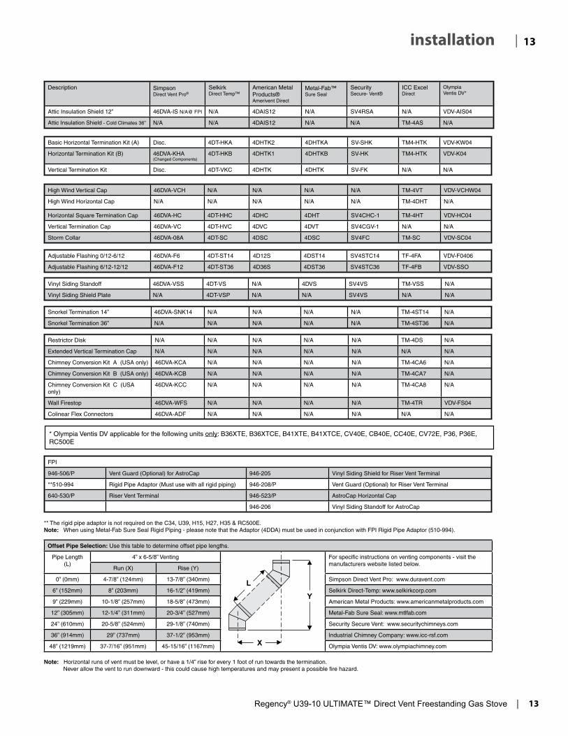
| 12 installation4” X 6-5/8” RIGID PIPE CROSS REFERENCE CHARTComponents from different Manufacturers may not be mixed. Not All Rigid Pipe components are available directly from FPI.
Description SimpsonDirect Vent Pro®
SelkirkDirect Temp™
American MetalProducts®Amerivent Direct
Metal-Fab™Sure Seal
SecuritySecure- Vent®
ICC Excel Direct
OlympiaVentis DV*
6” Pipe Length-Galvanized 46DVA-06 4DT-6 N/A 4D6 SV4L6 TC-4DL6 VDV-0406
6” Pipe Length-Black 46DVA-06B 4DT-6B N/A 4D6B SV4LB6 TC-4DL6B VDVB-0406
7” Pipe Length-Galvanized N/A N/A 4D7 N/A N/A N/A N/A
7” Pipe Length-Black N/A N/A 4D7B N/A N/A N/A N/A
9” Pipe Length-Galvanized 46DVA-09 4DT-9 N/A N/A N/A TC-4DL9 VDV-0409
9” Pipe Length-Black 46DVA-09B 4DT-9B N/A N/A N/A TC-4DL9B VDVB-0409
12” Pipe Length-Galvanized 46DVA-12 4DT-12 4D12 4D12 SV4L12 TC-4DL1 VDV-0412
12” Pipe Length-Black 46DVA-12B 4DT-12B 4D12B 4D12B SV4LB12 TC-4DL1B VDVB-0412
18” Pipe Length-Galvanized 46DVA-18 4DT-18 4D18 4D18 SV4LA TC-4DL18 VDV-0418
18” Pipe Length-Black 46DVA-18B 4DT-18B 4D18B 4D18B SV4LA TC-4DL18B VDVB-0418
24” Pipe Length-Galvanized 46DVA-24 4DT-24 4D24 4D24 SV4L24 TC-4DL2 VDV-0424
24” Pipe Length-Black 46DVA-24B 4DT-24B 4D24B 4D24B SV4LB24 TC-4DL2B VDVB-0424
36” Pipe Length-Galvanized 46DVA-36 4DT-36 4D36 4D36 SV4L36 TC-4DL3 VDV-0436
36” Pipe Length-Black 46DVA-36B 4DT-36B 4D36B 4D36B SV4LB36 TC-4DL3B VDVCB-0436
48” Pipe Length-Galvanized 46DVA-48 4DT-48 4D48 4D48 SV4L48 TC-4DL4 VDV-0448
48” Pipe Length-Black 46DVA-48B 4DT-48B 4D48B 4D48B SV4LB48 TC-4DL4B VDVB-0448
60” Pipe Length-Galvanized 46DVA-60 4DT-60 N/A N/A N/A N/A N/A
60” Pipe Length-Black 46DVA-60B 4DT-60B N/A N/A N/A N/A N/A
Adjustable Length 3”-10”-Galvanized N/A N/A N/A 4DAL N/A TC-4DLT N/A
Adjustable Length 3”-10”-Black N/A N/A N/A 4DALB N/A TC-4DLTB N/A
Adjustable Length 7”-Galvanized N/A N/A 4D7A N/A N/A N/A N/A
Adjustable Length 7”-Black N/A N/A 4D7AB N/A N/A N/A N/A
Extension Pipe 8-1/2”-Galvanized 46DVA-08A N/A N/A N/A N/A N/A N/A
Extension Pipe 8-1/2”-Black 46DVA-08AB N/A N/A N/A N/A N/A N/A
Adjustable Length 12”-Galvanized N/A N/A 4D12A N/A SV4LA12 TC-4dLSI N/A
Adjustable Length 12”-Black N/A N/A 4D12A N/A SV4LBA12 TC-4dLSIB N/A
Extension Pipe 16”-Galvanized 46DVA-16A N/A N/A N/A N/A N/A N/A
Extension Pipe 16”-Black 46DVA-16AB N/A N/A N/A N/A N/A N/A
45º Elbow-Galvanized 46DVA-E45 4DT-EL45 4D45L N/A N/A TE-4DE45 VDV-EL0445
45º Elbow-Black 46DVA-E45B 4DT-EL45B 4DT-EL45B N/A N/A TE-4DE45B VDVB-EL0445
45º Elbow Swivel-Galvanized See 46DVA-E45 N/A N/A 4D45L SV4E45 N/A N/A
45º Elbow Swivel-Black See 46DVA-E45B N/A N/A 4D45LB SV4EB45 N/A N/A
90º Elbow-Galvanized 46DVA-E90 4DT-EL90S 4DT-EL90S N/A N/A TE-4DE90 VDV-EL0445
90º Elbow-Black 46DVA-E90B 4DT-EL90SB 4DT-EL90SB N/A SV4EBR90-1 TE-4DE90B VDVB-EL0445
90º Elbow, Swivel-Galvanized See 46DVA-E90 N/A N/A 4D90L SV4E90-1 N/A N/A
90º Elbow, Swivel-Black See 46DVA-E90B N/A N/A 4D90LB SV4EB90-1 N/A N/A
90º Starter Elbow, Swivel-Galvanized N/A N/A N/A 4D90A N/A N/A N/A
Adaptor* N/A N/A N/A 4D90L N/A N/A VDV-UAA04
4” X 6-5/8” RIGID PIPE CROSS REFERENCE CHARTComponents from different Manufacturers may not be mixed. Not all rigid pipe components are available directly from Regency.Note: The listed manufacturers may have other lengths not shown on this chart, which would also be approved.
Ceiling Support N/A 4DT-CS 4DSP 4DFSP SV4SD TM4-RDS VDV-SCR04
Cathedral Support Box 46DVA-CS 4DT-CSS 4DRSB 4DRS SV4CSB TM4-SDS VDV-CSS04
Wall Support/Band 46DVA-WS 4DT-WS/B 4DWS 4DWS SV4BM TM-SWS VDV-WS04
Offset Support 46DVA-ES - N/A from FPI
4DT-OS N/A N/A SV4SU TM-SOS N/A
Wall Thimble-Black 46DVA-WT 4DT-WT 4DWT 4DWT SV4RSM N/A VDV-WPT04
Wall Thimble Support/Ceiling Support 46DVA-DC N/A N/A N/A SV4PF N/A N/A
Firestop Spacer 46DVA-FS 4DT-FS 4DFSP 4DFS SV4BF TM-4CS VDV-FS04
Trim Plate-Black N/A 4DT-TP 4DFPB 4DcP SV4LA TM-4TP VDV-WTC04
Regency® U39-10 ULTIMATE™ Direct Vent Freestanding Gas Stove | 13
13| installation
Description SimpsonDirect Vent Pro®
SelkirkDirect Temp™
American MetalProducts®Amerivent Direct
Metal-Fab™Sure Seal
SecuritySecure- Vent®
ICC Excel Direct
OlympiaVentis DV*
Attic Insulation Shield 12” 46DVA-IS N/A@ FPI N/A 4DAIS12 N/A SV4RSA N/A VDV-AIS04
Attic Insulation Shield - Cold Climates 36” N/A N/A 4DAIS12 N/A N/A TM-4AS N/A
High Wind Vertical Cap 46DVA-VCH N/A N/A N/A N/A TM-4VT VDV-VCHW04
High Wind Horizontal Cap N/A N/A N/A N/A N/A TM-4DHT N/A
Horizontal Square Termination Cap 46DVA-HC 4DT-HHC 4DHC 4DHT SV4CHC-1 TM-4HT VDV-HC04
Vertical Termination Cap 46DVA-VC 4DT-HVC 4DVC 4DVT SV4CGV-1 N/A N/A
Storm Collar 46DVA-08A 4DT-SC 4DSC 4DSC SV4FC TM-SC VDV-SC04
Restrictor Disk N/A N/A N/A N/A N/A TM-4DS N/A
Extended Vertical Termination Cap N/A N/A N/A N/A N/A N/A N/A
Chimney Conversion Kit A (USA only) 46DVA-KCA N/A N/A N/A N/A TM-4CA6 N/A
Chimney Conversion Kit B (USA only) 46DVA-KCB N/A N/A N/A N/A TM-4CA7 N/A
Chimney Conversion Kit C (USA only)
46DVA-KCC N/A N/A N/A N/A TM-4CA8 N/A
Wall Firestop 46DVA-WFS N/A N/A N/A N/A TM-4TR VDV-FS04
Colinear Flex Connectors 46DVA-ADF N/A N/A N/A N/A N/A N/A
Adjustable Flashing 0/12-6/12 46DVA-F6 4DT-ST14 4D12S 4DST14 SV4STC14 TF-4FA VDV-F0406
Adjustable Flashing 6/12-12/12 46DVA-F12 4DT-ST36 4D36S 4DST36 SV4STC36 TF-4FB VDV-SSO
Vinyl Siding Standoff 46DVA-VSS 4DT-VS N/A 4DVS SV4VS TM-VSS N/A
Vinyl Siding Shield Plate N/A 4DT-VSP N/A N/A SV4VS N/A N/A
Snorkel Termination 14” 46DVA-SNK14 N/A N/A N/A N/A TM-4ST14 N/A
Snorkel Termination 36” N/A N/A N/A N/A N/A TM-4ST36 N/A
Basic Horizontal Termination Kit (A) Disc. 4DT-HKA 4DHTK2 4DHTKA SV-SHK TM4-HTK VDV-KW04
Horizontal Termination Kit (B) 46DVA-KHA(Changed Components)
4DT-HKB 4DHTK1 4DHTKB SV-HK TM4-HTK VDV-K04
Vertical Termination Kit Disc. 4DT-VKC 4DHTK 4DHTK SV-FK N/A N/A
FPI
946-506/P Vent Guard (Optional) for AstroCap 946-205 Vinyl Siding Shield for Riser Vent Terminal
**510-994 Rigid Pipe Adaptor (Must use with all rigid piping) 946-208/P Vent Guard (Optional) for Riser Vent Terminal
640-530/P Riser Vent Terminal 946-523/P AstroCap Horizontal Cap
946-206 Vinyl Siding Standoff for AstroCap
** The rigid pipe adaptor is not required on the C34, U39, H15, H27, H35 & RC500E.Note: When using Metal-Fab Sure Seal Rigid Piping - please note that the Adaptor (4DDA) must be used in conjunction with FPI Rigid Pipe Adaptor (510-994).
Note: Horizontal runs of vent must be level, or have a 1/4” rise for every 1 foot of run towards the termination. Never allow the vent to run downward - this could cause high temperatures and may present a possible fi re hazard.
Offset Pipe Selection: Use this table to determine offset pipe lengths.
Pipe Length(L)
4” x 6-5/8” Venting For specifi c instructions on venting components - visit the manufacturers website listed below.
Run (X) Rise (Y)
0” (0mm) 4-7/8” (124mm) 13-7/8” (340mm) Simpson Direct Vent Pro: www.duravent.com
6” (152mm) 8” (203mm) 16-1/2” (419mm) Selkirk Direct-Temp: www.selkirkcorp.com
9” (229mm) 10-1/8” (257mm) 18-5/8” (473mm) American Metal Products: www.americanmetalproducts.com
12” (305mm) 12-1/4” (311mm) 20-3/4” (527mm) Metal-Fab Sure Seal: www.mtlfab.com
24” (610mm) 20-5/8” (524mm) 29-1/8” (740mm) Security Secure Vent: www.securitychimneys.com
36” (914mm) 29” (737mm) 37-1/2” (953mm) Industrial Chimney Company: www.icc-rsf.com
48” (1219mm) 37-7/16” (951mm) 45-15/16” (1167mm) Olympia Ventis DV: www.olympiachimney.com
* Olympia Ventis DV applicable for the following units only: B36XTE, B36XTCE, B41XTE, B41XTCE, CV40E, CB40E, CC40E, CV72E, P36, P36E, RC500E

14 | Regency® U39-10 ULTIMATE™ Direct Vent Freestanding Gas Stove
| 14 installation
RIGID PIPE VENTING SYSTEMSHorizontal or Vertical Terminations
Alternate Horizontal Ter-mination Caps
This product has been evaluated by Intertek for using a Rigid Pipe Adaptor in conjunction with Duravent Direct-Vent, Selkirk Direct-Temp, Ameri Vent Direct venting and Security Secure Vent systems. Use of these systems with the Rigid Pipe adaptor is deemed acceptable and does not affect the Intertek WHI listing of components.
WARNING:
Do not combine venting components from different venting systems.
However use of the the AstroCapTM and FPI Riser is acceptable with all systems.
When using Rigid Vent other thanSimpson Dura-Vent, 3 screws must be used to secure rigid pipe to adaptor.
The FPI AstroCapTM and FPI Riser Vent terminal are certified for installations using FPI venting systems as well as Simpson Dura-Vent® Direct Vent, Amer-ican Metal Products Ameri Vent Direct Vent, Security Secure Vent®, Selkirk Direct-Temp. AstroCapTM is a proprietary trademark of FPI Fireplace Products International Ltd. Dura-Vent® and Direct Vent are registered and/or proprietary trademarks of Simpson Dura-Vent Co. Inc.

Regency® U39-10 ULTIMATE™ Direct Vent Freestanding Gas Stove | 15
15| installation
INSTALLATION PRECAUTIONS
These venting systems are engineered products that have been designed and tested for use with the U39-NG10, and U39-LP10. The warranty will be voided and serious fire, health or other safety hazards may result from any of the following actions:
1. Installation of any damaged Direct Vent component
2. Unauthorized modification of the Direct Vent System
3. Installation of any component part not manufactured or approved by Simpson Dura-Vent or Fireplace Products International Ltd.
4. Installation other than as instructed by Simpson Dura-Vent and Fireplace Products International Ltd.
Warning: Always maintain required clearances (air spaces) to nearby combustibles to prevent a fire hazard. Do not fill air spaces with insulation.
Be sure to check the vent termination clearance requirements from decks, windows, soffits, gas regulators, air supply inlets and public walkways as specified in the "Exterior Vent Terminal Locations" section in your local building codes.
The gas appliance and vent system must be vented directly to the outside of the building, and never be attached to a chimney serving a separate solid fuel or gas-burning appliance. Each direct vent gas appliance must use its own separate vent system. Common vent systems are prohibited.
SAFETY PRECAUTIONS FOR THE INSTALLER1. Wear gloves and safety glasses for
protection.
2. Exercise extreme caution when using ladders or on roof tops.
3. Be aware of electrical wiring locations in walls and ceilings.
RIGID PIPE VENTING ARRANGEMENTS
Vertical Termination Systems for Residential Manufactured and Mobile Homes
The shaded area in the diagram below shows all allowable combinations of straight vertical and offset to vertical runs with vertical terminations. Maximum two 45o elbows.
If the vent is ENCLOSED in a chase (min. size 9" x 9") maintain a 1-1/4" clearance to combustibles.
May be installed in Manufactured (Mobile) Homes after first sale.
Horizontal Terminations for All Venting Systems
The shaded areas in the diagram below show all allowable combinations of vertical runs with horizontal terminations. Maximum one 90O elbow (two 45o elbows equal one 90o elbow).
Propane and Natural Gas: Residential, Manufactured and Mobile Homes Installations
The venting arrangements diagrammed below, have a min. of 75% (flue loss) efficiency with Fan Off, as required for manufactured homes. (Actual efficiency may be as high as 85%)
May be installed in Manufactured (Mobile) Homes after first sale.
Horizontal Run (Feet)
5'(
1.5
m)
Min
.
6'(
1.8
m)
5'(1.5m)
3' (.9m)
Min.1'(0.3m)
12'(3.7m)Max.
13' (4
.0m
)1
1
2
2
12
12
14
6
6
16
4
4
14
22
8
8
18
10
10
20
Ve
rtic
al H
eig
ht
(fe
et)
20'-
6"(6
.2)M
ax.
m
Vent Restrictor Position
To set the Vent restriction as indicated in the diagram, simply loosen the screws and push the vent restrictor plate to the correct position. Tighten the screws.
Vent Restrictor setting at 38,000 Btu/h
Vent Restrictor setting at 30,000 Btu/h

16 | Regency® U39-10 ULTIMATE™ Direct Vent Freestanding Gas Stove
| 16 installation
Horizontal Venting with Two (2. 90o Elbows
Option V H + H1 A) 3' Min. 2' Max. B) 5' Min. 3' Max. C) 8' Min. 4' Max. With these options, maximum total pipe length is 30 feet with minimum of 8 feet total vertical and maximum 4 feet total horizontal.Please note minimum 1 foot between 90o elbows is required.
One 90o elbow = Two 45o elbows.
Vertical Venting with Two (2. 90o Elbows
Option V H V1 V + V1 A) 1' Min. 1' Max. 1' Min. 2' Min. B) 1' Min. 2' Max. 2' Min. 3' Min. C) 2' Min. 3' Max. 2' Min. 4' Min. D) 2' Min. 4' Max. 2' Min. 4' Min. With these options, max. total pipe length is 30
feet with min. of 4 feet total vertical and max. 4 feet total horizontal.Please note min. 1 foot between 90o elbows is required.
One 90o elbow = Two 45o elbows.
Vent restrictor position A (fully open), Refer to the "Venting Ar-rangement" section.
Vent restrictor position A (fully open). Refer to the "Venting Arrangement" section.
Lengths do not include elbow indicated
Lengths do not include elbow indicated

Regency® U39-10 ULTIMATE™ Direct Vent Freestanding Gas Stove | 17
17| installation
DV STOVE HORIZONTAL VENT KIT INSTALLATIONReview the following sequence of instructions which are typical of most installations. The sequence may vary depending on wall thickness. Refer to vent
Min
imum
Inst
alla
tion
Hei
ght:
U39
: 59-
3/4"
( 15
18m
m)
DV STOVE HORIZONTAL VENT KIT (# 946-116 & #946-216)DV Stove Horizontal Vent Kit 2 ft. (Part # 946-116) or 4 ft. (Part # 946-216) includes all the parts needed to install the U39 with minimum horizontal and vertical vent dimensions. For installations that require longer vertical and/or horizontal vents see the "Dura-vent Termination Kit” and “Component" sections.
Qty. Description1. 1 Rigid Pipe Section (Kit # 946-116: 2 ft. (1.2m) length, Kit # 946-216: 4 ft. (1.2m) length), 6-1/2" (165mm) inside diameter 2. 1 Flex Liner, compressed aluminium 2 ply liner, 4" (102mm) inside diameter3. 4 spring spacers4. 1 90 deg. Elbow5. 1 Adjustable pipe section 13-1/2" to 24" (343mm x 610mm), 2 pieces6. 1 Thimble Cover7. 1 Wall Thimble (2 pcs.)8. 1 Adapter 9. 1 AstroCap Termination Cap10. 2 Trim Collar11. 1 tube of Mill-Pac, high temperature sealant12. 12 Screws, #8 x 1/2" Self tapping, Stainless Steel13. 13 Screws, #8 x 1/2" Self tapping, Black14. 4 Screws #8 x 1-1/2" Drill Point, Black15. 4 Screws #8 x 1-1/2" Drill Point, Stainless Steel16. 8 Wood screws #8 x 1"
Optional:946-206 Vinyl Siding Standoff for AstroCap
Note:
location and clearance dimensions in "Exterior Vent Termination Locations" to "DV Stove Horizontal Vent Kit" sections.
1. Set the unit in its desired location. Check to determine if wall studs will be in the way of the venting system, adjust location until all clearances are met and there are no obstructions.
Note: A 1-1/2"(38mm) clearance around the outer pipe must be maintained except that only a 1" (25mm) clearance is needed at the termination end.
IMPORTANT:Do not locate termination hood where excessive snow or ice buildup may occur. Be sure to check vent termination area after snow falls, and clear to prevent accidental blockage of venting system. When using snow blowers, make sure snow is not directed towards vent termination area.
2. Assemble a trial fit to determine the vertical center-line for the vent termination.
a) Cut a 9-1/2" x 9-1/2" (241mm x 241 mm) square hole on both the interior and exterior wall.
b) Install wall thimbles on both interior and exterior wall with 4 wood screws (#8 x 1") per thimble.
c) Attach the 2 piece adjustable pipe section to the vent terminal and slide into position from the exterior. The larger diameter end of the adjustable pipe goes to the vent terminal.
d) Install the 90o elbow onto the adjustable pipe to determine the vertical centerline of the starter collar on the unit.
Note: if the centerline cannot be met, the adjustable sections will have to be cut.
a) Liner sections should be continuous without any joints or seams.
b) This is an approved system, therefore components in this system must not be substituted for any other manufacturer's products.

18 | Regency® U39-10 ULTIMATE™ Direct Vent Freestanding Gas Stove
| 18 installation
Outside Wall
Mur extérieur
FurringStrips
Fourrures en bois
Furstrp.eps
see also c34020a.eps
furstrpf.epsfrench
e) Cut the 2 ft. or 4 ft. section of rigid pipe to length. Ensure that the pipe length when cut will seat onto both the starter collar and the 90o elbow. Crimped section of rigid pipe seats into the 90o elbow. Only cut the uncrimped side of pipe.
Dismantle all pipe sections including vent terminal.
3. Attach the 4" dia. flex liner to the vent terminal ensuring that the flex overlaps the collar of the vent terminal by a minimum of 1-3/8"(35mm). Use Mill-Pac to seal and secure with 3 of the #8 x 1/2" screws (stainless steel).
4. Attach the adjustable pipe section to the vent
terminal using Mill-Pac and attach with 3 of the #8 x 1/2" screws (stainless steel).
Note: The pipe seam should be facing down.
Note: To make the installation more aesthetically pleasing, we recommend framing out a square that the cap can be mounted on.
8. Cut the 4" dia. flex liner to the desired size.
Hint: leave an extra 12" to 16" of length, this will make the final assembly easier to work with.
9. Secure the 4" dia. flex liner to the 4" adapter with Mill-Pac and 3 of the #8 x 1/2" screws (stainless steel).
10. Slide the decorative Thimble Cover over the pipe sections and secure with 4 screws (#8 x 1-1/2" drill point, black) to the wall.
11. Slide the 90o elbow (crimp end up) and the 2 ft. or 4 ft. pipe section (crimp end up) over the 4" dia. flex liner.
12. Slide the trim collar over the adjustable pipe sections to cover the joint of the telescopic section.
13. Install the spring spacers onto the pipe sections.
14. Secure the 4" dia. flex liner with adapter onto the stove collar. Put a bead of Mill-Pac around the appliance adapter and secure with 3 screws (#8 x 1/2, stainless steel).
15. Attach the pipe section onto the starter collar by sealing with Mill-Pac and securing with 3 of the #8 x 1/2" (black) screws. Pipe seams should be facing the wall.
16. Attach the 90o elbow onto the pipe section by sealing with Mill-Pac and securing with 3 of the #8 x 1/2" screws (black).
17. Slide the adjustable pipe section onto the 90o elbow. The flex may have to be compressed back in order for the adjustable pipe to properly mate to the elbow. Seal with Mill-Pac and secure with 3 of the #8 x 1/2" screws (black). Pipe seams facing down.
18. Install the trim collar over the starter collar and secure with a #8 x 1/2" screw (black).
If the pipe needs to be touched up, use only Stove Brite High Temperature Metallic Black Stove Paint.
NOTE: For best results and optimum performance with each approved venting system, it is highly recommended to apply “Mill-Pac” sealant (supplied) to every inner pipe connection. Failure to do so may result in drafting or performance issues not covered under warranty.
that the termination is not recessed into the siding. For vinyl siding standoff installation refer to the Dura-Vent Termination instructions.
5. Slide the partially connected pipe and vent terminal assembly through the wall thimbles (from the exterior into the interior) and secure the cap to the exterior wall with 4 of the supplied screws (#8 x 1-1/2" drill point, stainless steel). Note: pilot holes will need to be drilled through the wall thimble on all 4 corners.
Note: The four screws provided for the vent cap should be replaced with appropriate fasteners for stucco, brick, concrete, or other types of sidings.
6. A bead of non-hardening mastic should be run around both the termination and vinyl siding standoff to prevent water from entering and to make a tight seal between the cap and the standoff.
7. Stretch the 4" dia. flex liner out fully and get a trial fit of the liner onto the 4" dia. starter collar.
Note: If installing termination on a siding covered wall, a vinyl siding standoff or furring strips must be used to ensure

Regency® U39-10 ULTIMATE™ Direct Vent Freestanding Gas Stove | 19
19| installation
Alternate Horizontal Termination Caps
Dura-Vent Basic Horizontal Kit
1 90o Elbow1 Wall Thimble Cover1 Horiz. Sq. Term. Cap
DURA-VENT TERMINATION KIT
Planning Your Dura-Vent Installation
There are two basic types of Dura-Vent Direct Vent System installations: horizontal termination and vertical termination. Confirm the maximum horizontal run and maximum vertical rise from the diagrams in the "Rigid Pipe Venting Arrangements" section.
When planning your installation, it will be necessary to select the proper length of vent pipe for your particular requirements. For horizontal installations, determine the minimum clearance from the rear of the unit to the wall. It is also important to note the wall thickness. (The wall thimble is suitable for 2 x 4 or 2 x 6 wall construction.) Select the amount of vertical rise desired for "vertical-to-horizontal" type installations.
Warning: Always maintain required clearances (air spaces) to nearby combustibles to prevent a fire hazard. Do not fill air spaces with insulation.
The minimum clearance requirements between the outer wall of the vent pipe and nearby combustible surfaces is 1-1/4 inch. Be sure to check the vent termination clearance requirements from decks, windows, soffits, gas regulators, air supply inlets and public walkways as specified in the "Exterior Vent Terminal Locations" section and in your local building codes.
To determine the length of vent pipe required for vertical installations, measure the distance from the unit flue outlet to the ceiling, the ceiling thickness, the vertical rise in an attic or second storey, and allow for sufficient vertical height above the roof line.
For multi-storey applications, fire stops are required at each floor level. If an offset is needed, additional pipe, elbows and supports will be required.
DURA-VENT VENTING COMPONENTSYou will require the following components with your new Regency® Direct Vent Freestanding Gas Stove. Please review your product to make sure you have everything you need. In the event that you are missing any part, contact your dealer.
Note: These are the minimum pieces required. Other parts may be required for your particular installation. See the "Dura-vent Horizontal Kit" section for a list of vent parts.
If installing termination on a siding covered wall, a vinyl siding standoff or furring strips can be used in order to ensure that the termination is not recessed into siding.
The vinyl siding standoff is required for walls with vinyl siding.
Minimum components for a Dura-Vent Horizontal Installation: A) Dura-Vent Horizontal Termination KitB) Wall Thimble (required for combus- tible walls)
Minimum components for a Dura-Vent Vertical Termination:
C) Dura-Vent Vertical Termination Kit See the "Rigid Pipe Venting Arrangments" section for pipe lengths.
The Simpson Dura-Vent Direct Vent System offers a complete line of component parts for installation of both horizontal and vertical installation. Many items are offered in decorative black, as well as galvanized finish. The galvanized pipe and fittings are used for concealed locations such as attics or where corrosion is a factor, such as above the roof line. Decorative brass trim kits are available for both wall thimbles and ceiling support boxes.

20 | Regency® U39-10 ULTIMATE™ Direct Vent Freestanding Gas Stove
| 20 installation
NOTE: For Snorkel terminations in ABOVE grade installations, follow national or local code requirements.
Diagram 3a
Note: Riser Vent is only for use in above grade terminations.
U39
: 59-
3/4"
(151
8mm
)
Diagram 2
Note: a) The horizontal run of vent should have
a 1/4 inch rise for every 1 foot of run towards the termination. Never allow the vent to run downward. This could cause high temperatures and may present the possibility of a fire.
b) The location of the horizontal vent termination on an exterior wall must meet all local and national building codes, and must not be blocked or obstructed. See instructions in the "External Vent Terminal Locations" section.
c) Snorkel Terminations: For installations requiring a vertical rise
on the exterior of the building, 14-inch and 36-inch tall Snorkel Terminations as shown in Dia. 3 are available, as well as the standard Riser Vent, see Dia. 3a. Follow the same installation procedures as used for standard Horizontal Termination. NEVER install the snorkel upside down.
*Dia 3, 3a & 4: As specified in CGA B149 Installation Code. Local codes or reg-ulations may require different clearances.
b) Horizontal runs of vent must be supported every three feet. Wall straps are available for this purpose.
3. With the pipe attached to the stove, slide the stove into its correct location, and mark the wall for a 10" x 10" (inside dimensions) square hole. The center of the square hole should line up with the centerline of the horizontal pipe, as shown in diagram 2. Cut and frame the 10 inch square hole in the exterior wall where the vent will be terminated. If the wall being penetrated is constructed of non-combustible material, i.e. masonry block or concrete, a 7" diameter hole is acceptable.
Diagram 3
DURA-VENTHORIZONTAL TERMINATIONS1. Set the unit in its desired location. Check
to determine if wall studs or roof rafters are in the way when the venting system is attached. If this is the case, you may want to adjust the location of the unit.
2. Direct Vent pipe and fittings are designed with special twist-lock connections to connect the venting system to the appliance flue outlet. A twist-lock appliance adaptor is installed on the unit at the factory. Assemble the desired combination of pipe and elbows to the appliance adaptor with pipe seams oriented towards the wall or ceiling, as much out of view as possible. The final positioning of the pipe and 90o elbow assembly is determined by the mounting orientation of the adaptor on the stove and twist-locked for a solid connection.
Diagram 1
Note: a) Twist-lock procedure: Four indentations,
located on the female ends of pipes and fittings, are designed to slide straight onto the male ends of adjacent pipes and fittings, by orienting the four pipe indentations so they match and slide in to the four entry slots on the male ends (diagram 1.. Push the pipe sections completely together, then twist-lock one section clockwise approximately one-quarter turn, until the two sections are fully locked. The female locking lugs will not be visible from the outside on the Black Pipe or fittings. They may be located by examining the inside of the female ends.
NOTE: For best results and optimum performance with each approved venting system, it is highly recom-mended to apply “Mill-Pac” sealant (supplied) to every inner pipe con-nection. Failure to do so may result in drafting or performance issues not covered under warranty.

Regency® U39-10 ULTIMATE™ Direct Vent Freestanding Gas Stove | 21
21| installation
Diagram 10
Diagram 9
Diagram 8
Diagram 7
Diagram 6
7. Install the Wall Thimble in the center of the 10" square and attach with wood screws.
8. Slide the decorative wall thimble up to the wall surface being careful not to scratch the paint and attach with screws provided. Apply decorative brass or chrome trim if desired. See diagram 7.
DURA-VENT VERTICAL TERMINATIONS
3. To install the Round Support Box/Wall Thimble in a flat ceiling, cut a 10 inch square hole in the ceiling centred on the hole drilled in Step 2. Frame the hole as shown in diagram 10.
Diagram 5
Note: If installing termination on a siding covered wall, a vinyl siding standoff or furring strips must be used to ensure that the termination is not recessed into the siding. The four wood screws provided should be replaced with appropriate fasteners for stucco, brick, concrete, or other types of sidings.
5. Before connecting the horizontal run of vent pipe to the vent termination, slide the black decorative wall thimble cover over the vent pipe, then slide the Wall Thimble over the vent pipe.
6. Slide the appliance and vent assembly towards the wall carefully inserting the vent pipe into the vent cap assembly. It is important that the vent pipe extends into the vent cap a sufficient distance so as to result in a minimum pipe overlap of 1-1/4 inches. Secure the connection between the vent pipe and the vent cap by attaching the two sheet metal strips extending from the vent cap assembly into the outer wall of the vent pipe. Use the two sheet metal screws provided to connect the strips to the pipe. Bend any remaining portion of the sheet metal strip back towards the vent cap, so it will be concealed by the decorative wall thimble cover. See diagram 6.
4. If installing the vent termination to a wall with vinyl siding, the Vinyl Siding Standoff must be used. Attach the Vinyl Siding Standoff to the Horizontal Vent Termination, but first run a bead of non-hardening mastic around its outside edges, so as to make a seal between vent cap and the standoff. Install the Vinyl Siding Standoff between the vent cap and the exterior wall and attach with the four wood screws provided. Seal around the Vinyl Siding Standoff on all four sides. Diagram 5. The arrow on the vent cap should be pointing up. Insure that the 1-1/4" clearances to combustible materials are maintained. See diagram 5.
Below Grade InstallationIf the Snorkel Termination must be installed below grade, i.e. basement application, proper drainage must be provided to prevent water from entering the Snorkel Termination. Refer to Dia. 4. Do not attempt to enclose the Snorkel within the wall, or any other type of enclosure.
Diagram 4
1. Ma in ta in the 1 -1 /4" clearances (air spaces) to combustibles when passing through ceilings, walls, roofs, enclosures, attic rafter, or other nearby combustible surfaces. Do not pack air spaces with insulation. Check the "Rigid Pipe Venting Arrangments" section for the maximum vertical rise of the venting system and the maximum horizontal offset limitations.
2. Set the gas appliance in its desired location. Drop a plumb bob down from the ceiling to the position of the appliance flue exit, and mark the location where the vent will penetrate the ceiling. Drill a small hole at his
point. Next, drop a plumb bob from the roof to the hole previously drilled in the ceiling, and mark the spot where the vent will penetrate the roof. Determine if ceiling joists, roof rafters or other framing will obstruct the venting system. You may wish to relocate the appliance or to offset, as shown in diagram 9 to avoid cutting load bearing members.

22 | Regency® U39-10 ULTIMATE™ Direct Vent Freestanding Gas Stove
| 22 installation
Diagram 11: The upper half of the flashing is installed under the roofing material and not
nailed down until the chimney is installed. This allows for small adjustments.
4. Assemble the desired lengths of black pipe and elbows necessary to reach from the appliance adaptor up though the Round Support Box. Insure that all pipes and elbow connections are in the fully twist-locked position and sealed.
5. Cut a hole in the roof centred on the small drilled hole placed in the roof in Step 2. The hole should be of sufficient size to meet the minimum requirements for clearance to combustibles of 1-1/4". Slip the flashing under the shingles (shingles should overlap half the flashing) as per diagram 11.
6. Continue to assemble pipe lengths.
Diagram 12
of the flashing to the roof with roofing rails, slide storm collar over the pipe section and seal with a mastic.
8. Install the vertical termination cap by twist locking it.
Notes: a) For multistory vertical installations,
a Ceiling Fire stop is required at the second floor, and any subsequent floor. Diagram 13. The opening should be framed to 10 " x 10" inside dimensions, in the same manner as shown in diagram 10.
b) Any occupied areas above the first floor,
Note: If an offset is necessary in the attic to avoid obstructions, it is important to support the vent pipe every 3 feet, to avoid excessive stress on the elbows, and possible separation. Wall straps are available for this purpose. See diagram 7.
Galvanized pipe and elbows may be utilized
in the attic as well as above the roofline. The galvanized finish is desirable above the roofline due to its higher corrosion resistance.
Continue to add pipe sections through the flashing until the height of the vent cap meets the minimum height requirements specified in diagram 12 or local codes. Note that for steep roof pitches, the vertical height must be increased. A poor draft, or down drafting can result from high wind conditions near big trees or adjoining roof lines, in these cases, increasing the vent height may solve the problem.
7. Ensure vent is vertical and secure the base
Offset Chart
Diagram 13
including closets and storage spaces, through which the vertical vent passes, must be enclosed.
CATHEDRAL CEILINGS
Round Support (RDS) &Square Support (SQS)
If your home has a cathedral ceiling (no attic space between the ceiling and the roof), install the chimney and support as follows.
1. Situate the chimney in a convenient location as near as possible to the appliance outlet. Cut and frame a hole in the roof for the support. The sides of this hole must be vertical with 1 1/4" clearance.
2. Place the support in the opening. Lower it to the correct height as determined by the table and diagram below.
Using a level, make sure the support is vertical.
Slope "X"0/12-2/12 4"
2/12-7/12 5-1/2"
7/12-12/12 6-3/4"
12/12-24/12 7-1/2"
24/12+ 12-1/2"
Roof Pitch Minimum Vent Height
Feet Meters
flat to 7/12 2 0.61
over 7/12 to 8/12 2 0.61
over 8/12 to 9/12 2 0.61
over 9/12 to 10/12 2.5 0.76
over 10/12 to 11/12 3.25 0.99
over 11/12 to 12/12 4 1.22
over 12/12 to 14/12 5 1.52
over 14/12 to 16/12 6 1.83
over 16/12 to 18/12 7 2.13
over 18/12 to 20/12 7.5 2.29
over 20/12 to 21/12 8 2.44

Regency® U39-10 ULTIMATE™ Direct Vent Freestanding Gas Stove | 23
23| installation
If the support extends above the roof, cut it flush with the top of the roof. Nail the support to the frame opening using (8) 3" spiral nails or #8 x 1-1/2" screws.
Note: If you are using a 6" square support you may find it difficult to screw it in place because it is fairly small inside.
Simpson Dura-Vent has provided angle brackets with this support which can be screwed to the outside of the support box and nailed to surrounding framing as required. Use a minimum of four #8 x 1/2" screws per bracket. In some cases these brackets may need to be trimmed (e.g.: to fit under a flashing). Place the Finish Collar around the support and fasten it to the ceiling using the screws provided.
3. Use appropriate roof flashing. Place the flashing under the upper shingles and on top of the lower shingles approximately half of the flashing should be under the shingles.
4. Assemble the desired lengths of Black Pipe and Elbows necessary to reach from the appliance adaptor up through the support box and flashing to proper height as per Dia. 12, local codes or the "Rigid Pipe Venting Arrangements" section. Ensure that all pipe and elbow connections are in their fully twist lock position.
5. Ensure vent is vertical and secure flashing to the roof with roofing nails. Slide the storm collar over the pipe section and seal with a mastic.
6. Twist lock the vent cap on to the last section.
Support Extensions - Round (RDSE) or Square (SQSE)
Steep pitched cathedral ceilings may require the use of a support extension. This piece fits down inside the support and can be adjusted to increase the support's length by up to 22". The extension is attached to the support using the eight metal screws provided. Be sure there is at least a 2 inch overlap where the extension joins the support.
CONVERTING A CLASS-A METAL CHIMNEY TO A DIRECT VENT SYSTEM
General
There are two different types of direct vent Prior to installation and connection of the vent system to a factory-built or masonry chimney, the chimney must be inspected and thoroughly cleaned by a qualified service person, such as a certified chimney sweep or home inspection service. The direct vent system must not be connected to a damaged factory-built or masonry chimney.
For factory built, zero clearance, and masonry chimneys cleanout doors and caps or plugs for cleanout tee fittings and ash dumps shall be secured in place and sealed before installing a Direct Vent system within the chimney.
If the appliance shuts off during operation, contact a qualified service person to determine if a negative pressure and/or leaky chimney condition exists. Do not operate the appliance until the problem is corrected.
Approved for US Installations OnlyThe use of an existing chimney as an air intake is not covered under the CGA 2.17-M91, Z21.88-2014 • CSA 2.33-2014. test methods and the resulting ITS/WHI product certification. The code Authority Having Jurisdiction must be consulted prior to proceeding with this installation method.
Diagram 1
Diagram 2
Converting a Factory Built Metal Chimney
1. Remove the existing chimney cap.
2. Measure the distance from the top end of the chimney to the bottom of the ceiling support box, add 3” (76mm) to this measurement, and cut a section of the 4” flex pipe to that length (the flex should already be extended to its nominal length).
3. Connect the end of the flex pipe section to the underside of the Top Adaptor using 3 sheet metal screws.
Diagram 2.
4. Pass the flex pipe down through the center of the chimney system, and center the adaptor on the top of the chimney pipe. Drill four 1/8" diameter holes through the adaptor and into the chimney top. Insure that you are in fact, drilling into the metal on the chimney. Twist-lock the Termination Cap onto the Adaptor. (Diagram 3 and 4).

24 | Regency® U39-10 ULTIMATE™ Direct Vent Freestanding Gas Stove
| 24 installation
Converting a Masonry Chimney
Important: The existing masonry flue opening needs to have an area of at least a 36 sq. in. to insure proper intake/exhaust flow.
1. Before cutting any holes, assemble the desired sections of black direct vent pipe to determine the center of the masonry penetration.
2. Once the center point of the penetration has
Diagram 6
been determined, cut a 6" (152mm) dia. hole in the masonry. Be careful, if the hole is too large, the Retro Connector might not mount properly, and if the hole is too small, then the appliance might starve for intake air. If there is a frame wall in front of the masonry wall, cut and frame a 10" (254mm) clear square opening in the wall (centered around the 6" (152mm) masonry opening). If there is sheet rock only (no studs) in front of the masonry, the 10" (254mm) clear opening is still needed, but does not need to be framed. This allows the Retro Connector to mount directly on the masonry and provide clearance to the combustibles. Diagram 11.
3. Secure the Flashing to the top of the masonry chimney using a bead of non-hardening sealant-adhesive. If the Flashing is larger than the top of the chimney, then cut and fold flashing as needed to fit chimney. Diagram 7.
Diagram 7
4. To determine the length of flex required, measure from 3" (76mm) above the top of the Flashing down to the level of the opening. Add to this measurement the distance from the center of the chimney to out through the wall. Cut a piece of 4" flex to this length (the flex should already be extended to its nominal length).
5. Connect the 4" flex liner to the Top Adaptor using 3 sheet metal screws. Diagram 2.
6. Feed the 4" flex liner through the Flashing into the chimney. Continue to feed the liner out through the opening in the masonry wall.
7. Secure the Top Adaptor to the Flashing. Use 3 sheet metal screws through the side of the adaptor into the flange on the Flashing (diagram 8). Twist lock the Termination Cap on to the Top Adaptor.
Diagram 88. Attach the flex to the Retro Connector. Use 3
sheet metal screws to attach the flex liner to the Connector. Diagram 9. Mount the Retro Connector to the masonry wall using masonry bolts. Re-drill larger holes on connector as needed. Be careful to insure that the connector is centered in the opening and the mounting holes line up with the masonry wall.
Diagram 3
Diagram 4
Diagram 5
7. The connection between the appliance and the Retro Connector may be completed with sections of black direct vent pipe, together with an adjustable length.
5. Pull the flex pipe down through the ceiling support box, until it protrudes approximately 3" (76mm). Connect the flex pipe to the Retro Connector by slipping it into the 4-3/4" diameter sleeve on the top side of the Connector. Use 3 sheet metal screws to assemble these two parts.
6. Push the flex pipe back up into the ceiling support box, center the Retro Connector, and attach it to the support box, or decorative sleeve for double wall solid packed pipe, with the sheet metal screws (supplied). The holes in the Retro Connector are pre-punched. Diagram 5.
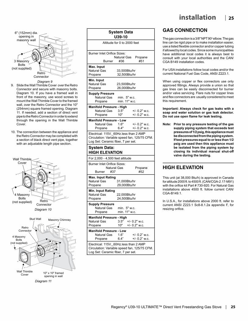
Regency® U39-10 ULTIMATE™ Direct Vent Freestanding Gas Stove | 25
25| installation
GAS CONNECTION
The gas connection is a 3/8" NPT 90o elbow. The gas line can be rigid pipe or to make installation easier, use a listed flexible connector and/or copper tubing if allowed by local codes. Since some municipalities have additional local codes it is always best to consult with your local authorities and the CAN/CGA B149 installation codes.
For USA installations follow local codes and/or the current National Fuel Gas Code, ANSI Z223.1.
When using copper or flex connectors use only approved fittings. Always provide a union so that gas lines can be easily disconnected for burner and/or valve servicing. Flare nuts for copper lines and flex connectors are usually considered to meet this requirement.
Important: Always check for gas leaks with a soap and water solution or gas leak detector. Do not use open flame for leak testing.
Note: Prior to any pressure testing of the gas supply piping system that exceeds test pressures of 1/2 psig, this appliance must be disconnected from the piping system. If test pressures equal to or less than 1/2 psig are used then this appliance must be isolated from the piping system by closing its individual manual shut-off valve during the testing.
HIGH ELEVATION
This unit (at 38,000 Btu/h) is approved in Canada for altitude 2000 ft. to 4500 ft. (CAN/CGA-2.17-M91) with the orifice kit Part # 730-920. For Natural Gas installations above 4500 ft. follow current CAN/CGA-B149.1.
In U.S.A., for installations above 2000 ft. refer to current ANSI Z223.1 Sc8-8.1.2a appendix F, for resizing orifice.
Diagram 99. Slide the Wall Thimble Cover over the Retro
Connector and secure with masonry bolts. Diagram 10. If you have a framed wall in front of the masonry, use wood screws to mount the Wall Thimble Cover to the framed wall, over the Retro Connector and the 10" (254mm) square framed opening. Diagram 11. If needed, add a section of direct vent pipe to the Retro Connector in order to extend through the opening in the Wall Thimble Cover.
10. The connection between the appliance and the Retro Connector may be completed with a section of black direct vent pipe, together with an adjustable length pipe section.
Diagram 10
Diagram 11
System DataU39-10
Altitude for 0 to 2000 feet
Burner Inlet Orifice Sizes: Natural Gas Propane Burner #36 #51
Max. InputNatural Gas 33,500Btu/hrPropane 32,500Btu/hr
Min. Input Natural Gas 23,500Btu/hrPropane 26,000Btu/hr
Supply Pressure Natural Gas min. 5" w.c. Propane min. 11" w.c.
Manifold Pressure - High Natural Gas 3.5" +/- 0.2" w.c. Propane 10" +/- 0.2" w.c.
Manifold Pressure - Low Natural Gas 1.6" +/- 0.2" w.c. Propane 6.4" +/- 0.2" w.c.
Electrical: 115V._60Hz.less than 2 AMPCirculation: Variable speed fan, 125/75 CFM.Log Set: Ceramic fiber, 7 per set.
System Data: HIGH ELEVATIONFor 2,000 - 4,500 feet altitude
Burner Inlet Orifice Sizes: Natural Gas Propane Burner #37 #52
Max. Input RatingNatural Gas 31,000Btu/hrPropane 29,000Btu/hr
Min. Input RatingNatural Gas 22,000Btu/hrPropane 24,500Btu/hr
Supply Pressure Natural Gas min. 5" w.c. Propane min. 11" w.c.
Manifold Pressure - HighNatural Gas 3.5" +/- 0.2" w.c.Propane 10" +/- 0.2" w.c.
Manifold Pressure - Low Natural Gas 1.6” +/- 0.2” w.c. Propane 6.4” +/- 0.2” w.c.
Electrical: 115V._60Hz.less than 2 AMPCirculation: Variable speed fan, 125/75 CFM.Log Set: Ceramic fiber, 7 per set.

26 | Regency® U39-10 ULTIMATE™ Direct Vent Freestanding Gas Stove
| 26 installation
CONVERSION FROM NG TO LP
THIS CONVERSION MUST BE DONE BY A QUALIFIED GAS FITTERIF IN DOUBT DO NOT DO THIS CONVERSION !!
919-504 04.24.181
Conversion from NG to LPG using SIT 829 NOVA Gas Valve
THIS CONVERSION MUST BE DONE BY A QUALIFIED GAS FITTERIF IN DOUBT DO NOT DO THIS CONVERSION !!
1. Shutoffthegasandelectricalsupply.
2. Removethesafetyscreen,openthefrontdoorandcarefullyremovethelogsandlavarock.
Pilot assembly is now accessible .
Each Kit contains one LPG Conversion Kit LPG Conversion Kit Contains:Qty. Part # Description1 904-529 5/32"AllenKey1 904-641 BurnerOrifice#501 918-590 Label"Convertedto LPG"1 908-528 Red"LPG"label1 910-037 LPGInjector (PilotOrifice)1 910-582 Steppermotor1 919-504 InstructionSheet
Note: Use a magnetic type screwdriver if possible.
4. Openpedestaldoorandremovethechainfromdoorwhichwillallowdoortofall.
3. Removeburner.Seediagrambelow.
7. Turncontrolknobtothe“OFF”position.
8. RemoveNGsteppermotorbyremoving3screwsinlocationsshownbelow–replacewithLPsteppermotor,secureinplacewith3screws.
9. Pulloffthepilotcaptoexposethepilotorifice.
10.UnscrewthepilotorificewiththeallenkeyandreplacewiththeLPGpilotorificeinthekit.
11.ReinstallnewburnerorificeLPGstamped#50andtighten.
13.Checkforgasleakswithapropersoapysolutionorleakdetector.
14.Checkforpropersparkbetweentheignitorandpilotcap.Referto"LightingProcedure"sectionofthemanualforlightingsequence.
15.Checkpilotflames.Correctflamepat-ternhas3strongblueflames.Adjust-mentcanbemadebyturningtheslottedscrewatthetoprightcornerofthevalve.Referto"MaintenanceInstruc-tions"sectionofthemanualforcorrectflamepatterns.
16. ReverseSteps9-1.
17.Attachthelabel"ThisunithasbeenconvertedtoLPG"nearorontopoftheSerial#decal.
18.Replaceyellow"NG"labelwithred"LPG"label.
19.Checkoperationofflamecontrol.
20.Theburneraerationshouldbesetto1/2"openforLP.
Seeaerationadjustmentdetailsinthemanual.
21.Checkforproperflameappearanceandglowonlogs.
Burner Orifice
12.Removeburnerorificewitha1/2"wrenchwhileusinga9/16"wrenchtoholdontotheelbowbehindtheorifice,thendiscardtheorifice.
Installer Notice:These instructions must be left
with the appliance.
6.Removefourscrewstoremovetheac-cesspanel(inlocationsshownbelow)andthechainattachedtothefrontdoorandtheunit.
Removechainhere
5.Remove2screwsthatsecurethefrontdoortotheunit.Onescrewisonthelefthandsideandtheotherontherighthandside.(Leftsideshown).

Regency® U39-10 ULTIMATE™ Direct Vent Freestanding Gas Stove | 27
27| installation
GAS PIPE PRESSURE TESTING
The appliance must be isolated from the gas supply piping system by closing its individual manual shut-off valve during any pressure testing of the gas supply piping system at test pressures equal to or less than 1/2 psig. (3.45 kPa). Disconnect piping from valve at pressures over 1/2 psig.
CONVERSION TO LOWER BTU RATING
THIS CONVERSION MUST BE DONE BY A QUALIFIED GASFITTER IF IN DOUBT DO NOT DO THIS CONVERSION !!
Natural Gas Conversion Kit 730-920 Contains:Qty. Part # Description1 904-240 Burner Orifice #37 (Natural Gas)1 918-034 Decal "Converted to 30,000 Btu"1 918-033 Instruction Sheet
Propane Conversion Kit 730-922Contains:Qty. Part # Description1 904-390 Burner Orifice #52 (Propane)1 918-034 Decal "Converted to 30,000 Btu"1 918-033 Instruction Sheet
1. Shut off the gas and electrical supply.
2. Remove the safety screen - open the front door. Carefully remove the logs and lava rock.
3. Remove burner. See diagram below.
Burner Orifice
4. Remove burner orifice with a 1/2" wrench and discard.
The manifold pressure is controlled by a regulator built into the gas control, and should be checked at the pressure test point.
Note: To properly check gas pressure, both inlet and manifold pressures should be checked using the valve pressure ports on the valve.
1. Make sure the valve is in the "OFF" position.
2. Loosen the "IN" and/or "OUT" pressure tap(s), turning counterclockwise with a 1/8" wide flat screwdriver.
3. Attach manometer to "IN" and/or "OUT" pressure tap(s) using a 5/16" ID hose.
4. Light the pilot and turn the valve to "ON" position. Read manometer.
5. The pressure check should be carried out with the unit burning and the setting should be within the limits specified on the safety label.
6. When finished reading manometer, turn off the gas valve, disconnect the hose and tighten the screw (clockwise) with a 1/8" flat screwdriver. Note: Screw should be snug, but do not over tighten
5. Reinstall new burner orifice (NG stamped #37 or LP stamped #52) and tighten.
6. Reverse steps 3. and 2.
7. Adjust Vent restrictor setting: To set the Vent restriction as indicated in the diagram, simply loosen the screws and push the vent restrictor plate to the correct position. Tighten the screws.
Unit Btu/h Restrictor Opening U39 38,000 A 1-3/4" (44mm) 30,000 B 1-1/4" (32mm)
Vent Restrictor set-ting at High Btu/h
Vent Restrictor set-ting at Low Btu/h
8. Attach the label "This unit has been converted to..." on top of the Serial # decal over the higher Btu information.
9. Check for gas leaks.
10. Check inlet and outlet pressures.
11. Check operation of flame control. Check for proper flame appearance and glow on logs.
Note: Use a magnetic type screwdriver if possible.

28 | Regency® U39-10 ULTIMATE™ Direct Vent Freestanding Gas Stove
| 28 installation
AERATION ADJUSTMENT
The burner aeration is factory set but may need adjusting due to either the local gas supply or altitude. U39 with 38,000 Btu/hU39-NG10 Natural Gas: 1/4" openU39-LP10 Propane: 1/2" open
U39 with 30,000 Btu/hU39-NG10 Natural Gas 3/16" openU39-LP10 Propane 3/8" open
The aeration adjustment gears are located on the right side of the burner box and can be accessed from the side or from the front when the louvers are removed.
To adjust the aeration: use the allen key to turn
the turning gear which will adjust the air shutter. Open the air shutter for a blue flame or close it for a yellower flame.
Caution: Carbon will be produced if the air shutter is closed too much.
Note: Any damage due to carboning resulting from improperly setting the aeration controls is NOT covered under warranty.
Note: Aeration Adjustment should only be performed by an authorized Regency® Installer at the time of installation or service.
Clockwise to open,counter-clockwise to close.
SIT 829 VALVE DESCRIPTION
1. Gas on/off knob2. Electronically Operated Hi/Lo3. Pilot Adjustment4. Thermocouple Connection - option5. Outlet Pressure Tap6. Inlet Pressure Tap7. Pilot Outlet8. Main Gas Outlet9. Alternative TC Connection Point

Regency® U39-10 ULTIMATE™ Direct Vent Freestanding Gas Stove | 29
29| installation
LOG SET INSTALLATION
04.05.18918-039b
U38 / U39
LOG SET INSTALLATIONRead the instructions below carefully and refer to the diagrams. If logs are broken do not use the unit until they are replaced. Broken logs can interfere with the pilot operation.
The "02" refer numbers (i.e. 02-65) are molded into the rear of each log.
Pins on Rear Log Support
A
B
3. Place the Middle Left Log B on the two pins as shown.
The gas log kit contains the following:
a) 02-65 Rear Log b) 02-56 Middle Left Logc) 02-44 Front Left Log d) 02-46 Left Top Log e) 02-45 Front Right Log f) 02-47 Center Log g) 02-48 Middle Right Log
C
4. Place Front Left Log C onto the 2 front pins as shown.
CutoutPin
D
B
A
5. Place the Left Top Log D on the pin on Log B and on top of the cut-out on Log A.
C
1. Carefully remove the logs from the box and unwrap them. The logs are fragile, handle with care - do not force into position.
2. Place Rear Log A on the two pins on the rear log support.

30 | Regency® U39-10 ULTIMATE™ Direct Vent Freestanding Gas Stove
| 30 installation
04.05.18918-039b
U38 / U39
E
6 Place Front Right Log E on the two pins as shown.
CutoutNotch
F
E
A
7. Place the notch in Center Log F over Log E and across the cut-out on Log A.
Notch
A
G
E
F
8. Position notch in Front Right Log G on Log F and push the bottom right edge against the bracket on the burner tray.
E
Bracket
The bottom right edge of Log G must sit snugly against the bracket
Side View
G
9. Take the Embaglow, (steel wool like material) lightly separate it and set a small amount over the visible burner ports in front and between the front left log and the log under the “Y” log, indicated in the picture.
IMPORTANT: DO NOT compress this material down on the burner ports.
Embaglow
10. Next, take the white Platinum Ember material (provided) and gently separate the layers until you have a fi ne layer to place onto the Embaglow (steel wool type media).
Platinum Embers

Regency® U39-10 ULTIMATE™ Direct Vent Freestanding Gas Stove | 31
31| installation
04.05.18918-039b
U38 / U39
12. Test fi re to ensure proper light off (make sure fl ame fl ows smoothly from one end of burner to the other. If there is any fl ame hesitation, check that area for any blockage of the burner port.
F)02
-47
E)02-45
A)02-65G)02-48
D)02-
46B)02-56
C)02-44
11. Using the harder coal like embers carefully spread these around the OUTSIDE of the burner (1 cup on each side). Do not place or use these hard material embers on top of the burner.
Coal Embers--outside burner only!
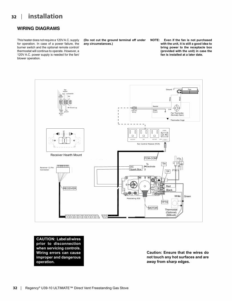
32 | Regency® U39-10 ULTIMATE™ Direct Vent Freestanding Gas Stove
| 32 installation
WIRING DIAGRAMS
This heater does not require a 120V A.C. supply for operation. In case of a power failure, the burner switch and the optional remote control/thermostat will continue to operate. However, a 120V A.C. power supply is needed for the fan/blower operation.
(Do not cut the ground terminal off under any circumstances.)
NOTE: Even if the fan is not purchased with the unit, it is still a good idea to bring power to the receptacle box (provided with the unit) in case the fan is installed at a later date.
Caution: Ensure that the wires do not touch any hot surfaces and are away from sharp edges.
CAUTION: Label all wires prior to disconnection when servicing controls. Wiring errors can cause improper and dangerous operation.
ENG
LISH
REM
OTE
TP
TH
TPTH
MOTOR
RECEIVER
FCM-COM
GreenWhite
Red
Black
(+) (-)
Ground
Green
Neutral
Bla
ck
Fan Thermodisc
(Normally Open)
Ground
120V AC
60 Hz
Fan
White
Thermodisc Cage
Live
Thermostat
(Optional)
(Millivolt)
DC
Spark Box
To
Electrode
Lockwasher
Fan
ground
Power
cord
ground
wire
Star
washer
Nut
Nut
#8 Ground Lug
Star
washer
Receiver Hearth Mount

Regency® U39-10 ULTIMATE™ Direct Vent Freestanding Gas Stove | 33
33| installation
Thermostat Wire Table
OPTIONAL WALL THERMOSTAT
A wall thermostat may be installed if desired. Connect the wires as per the wiring diagrams. Note that the wires are connected to the "TH" on the gas valve. Use table below to determine the maximum wire length:
Note: Preferable if the thermostat is installed on an interior wall.
Regency® offers an optional programmable thermostat but any 250-750 millivolt rated non-anticipator type thermostat that is CSA, ULC or UL approved may be used.
CAUTIONDo not connect the millivolt
wall thermostat wires to the 120V wires.
FINAL CHECK
Before leaving this unit with the customer, the installer must ensure that the appliance is firing correctly. This includes:
1. Clocking the appliance to ensure the correct firing rate (rate noted on label) at 15 minutes.
2. If required, adjusting the primary air to ensure that the flame does not carbon. First allow the unit to burn for 15 min. to stabilize.
3. Check for proper draft.
CAUTIONAny alteration to the product that causes sooting or carboning that results in damage to the exterior facia is not the responsibility of the manufacturer.
Recommended Maximum Lead Length (Two-Wire) When Using Wall Thermostat (CP-2 System)
Wire Size Max. Length14 GA. 50 Ft.16 GA. 32 Ft.18 GA. 20 Ft.20 GA. 12 Ft.22 GA. 9 Ft.
DC SPARK IGNITER BATTERY INSTALL
3. Remove four screws to remove the access panel (in locations shown below) and the chain attached to the front door and the unit.
Remove chain here
Install supplied battery into the DC spark box.
1. Open pedestal front door.
2. Remove 2 screws that secure the front door to the unit. One screw is on the left hand side and the other on the right hand side. (Left side shown).
4. The DC spark box will be exposed after re-moving the valve cover.
DC Spark Box
5. Open the battery compartment door on the DC spark box
6. Install battery into DC spark box.
7. Reverse steps 1 to 5.

34 | Regency® U39-10 ULTIMATE™ Direct Vent Freestanding Gas Stove
| 34 operating instructionsFIRST FIRE
The first fire in your stove is part of the paint curing process. To ensure that the paint is properly cured, it is recommended that you burn your fireplace for at least four (4) hours the first time you use it with the fan on. When first operated, the unit will release an odour caused by the curing of the paint, the burning off of any oils remaining from manufacturing. Smoke detectors in the house may go off at this time. Open a few windows to ventilate the room for a couple of hours.
The glass panel may require cleaning after the unit has cooled down.
DO NOT ATTEMPT TO CLEAN THE GLASS WHILE IT IS HOT.
Note: When the glass is cold and the appliance is lit, it may cause condensation and fog the glass. This condensation is normal and will disappear in a few minutes as the glass heats up.
OPERATING INSTRUCTIONS
1. Read and understand these instructions before operating this appliance.
2. Check to see that all wiring is correct and enclosed to prevent possible shock.
3. Check to ensure there are no gas leaks.
4. Make sure the glass in the door frame is properly positioned. Never operate the appliance with the glass removed.
5. Verify that the venting and cap are unobstructed.
6. Verify log placement. If the pilot cannot be seen when lighting the unit, the logs have been incorrectly positioned.
7. The unit should never be turned off, and on again without a minimum of a 60 second wait.
8. Hook up remote receiver to wire marked 're-
During the first few fires, a white film may develop on the glass front as part of the curing process. The glass should be cleaned or the film will bake on and become very difficult to remove. Use a non-abrasive cleaner and NEVER clean the glass while it is hot.
Proflame video
DO NOT BURN THE APPLIANCE WITHOUT THE GLASS FRONT IN PLACE.
ceiver' which will be located on the bottom of the appliance. This remote control requires coding. See remote control instructions for details.
NOTE: This appliance will operate during power outages. Only the fan will not operate until power is restored. If the remote batteries in both the handheld transmitter or receiver lose power, the appliance can still be operated by sliding the switch on the receiver switch from "Remote" to "ON". To turn on the appliance off slide the receiver switch from "ON" to "Remote" or "OFF".
IMPORTANT: The remote control system supplied with this appliance has several options for start-ing/operating the appliance, please read the remote control operating instructions (packed with remote control) to understand how to op-erate this remote system. You can download remote functions video with the QR code below..
LIGHTING PROCEDURE
Important: If the pilot does not hold, turn pilot knob to "OFF" position. Wait 5 minutes to clear gas. If you smell gas - STOP! Follow the safety information above. If you don't smell gas, repeat Steps 1-6.
1. Push in gas control knob slightly and turn to "PILOT" position.
2. Push in control knob all the way and hold in until the pilot lights up. Continue to hold the control knob in for about 20 seconds after the pilot is lit. Release knob.
3. Push in gas control knob slightly and turn to "ON" position.
4. Ensure the receiver is in the remote position.
IMPORTANTPrior to igniting or re igniting the pilot, remove the glass door.
Set Switch to Remote
Diagram 1
5. Press and release the ON/OFF button on the remote handheld transmitter. An audible beep should be heard from the receiver.
ON/OFF Button
6. The unit will turn on.
SHUTDOWN PROCEDURE
1. Press "OFF" on the remote or slide receiver switch from remote to "OFF".
2. Turn the gas control knob to the "OFF" position to turn off the pilot.
Pilot may be shut off during prolonged non use periods to conserve fuel.
Diagram 2
Remote shown in Manual Mode on Hi

Regency® U39-10 ULTIMATE™ Direct Vent Freestanding Gas Stove | 35
35| operating instructionsCopy Of Lighting Plate Instructions
919-456
Part #: 919-456
Colours: Black on Grey, except for parts indicated as being Red.
Size: 100% 5.2" x 9.6"
Sept. 23/14: Created decal
A) This appliance is equipped with an ignition device which automatically lights the pilot. Do not try to light the pilot by hand.B) BEFORE OPERATING smell all around the appliance area for gas. Be sure to smell next to the fl oor because some gas is heavier than air and will settle on the fl oor. WHAT TO DO IF YOU SMELL GAS
- Do not try to light any appliance.- Do not touch any electric switch, do not use any phone in your building.- Immediately call your gas supplier from a neighbours phone. Follow the gas supplier’s instructions.- If you cannot reach your gas supplier, call the fi re department.
C) Do not use this appliance if any part has been under water. Immediately call a qualifi ed service technician to inspect the appliance and replace any part of the control system and any gas control which has been underwater.A) Cet appareil est muni d’un dispositif d’allumage qui allume automatiquement la veilleuse. Ne tentez pas d’allumer la veilleuse manuellement. B) AVANT LA MISE EN MARCHE, renifl ez tout autour de l’appareil pour déceler une odeur de gaz. Renifl ez au niveau
du plancher, car certains gaz sont plus lourds que l’air et peuvent s’accumuler au niveau du sol. QUE FAIRE SI VOUS SENTEZ UNE ODEUR DE GAZ : • Ne tentez pas d’allumer d’appareil • Ne touchez à aucun interrupteur; n'utilisez pas de téléphones se trouvant dans le bâtiment. • Appelez immédiatement votre fournisseur de gaz depuis un téléphone extérieur. Suivez les instructions du fournisseur. • Si vous ne pouvez pas rejoindre le fournisseur, appelez le service incendie.C) N’utilisez pas cet appareil s’il a été plongé dans l’eau, même partiellement. Faites inspecter l’appareil par un tech-
nicien qualifi é et remplacez tout élément du système de contrôle ou de commande qui a été plongé dans l’eau.
DO NOT REMOVE THIS INSTRUCTION PLATE
TO TURN OFF GAS APPLIANCE
This appliance must be installed in accordance with local codes, if any;if none, follow the National Fuel Gas Code, ANSI Z223.1/NFPA 54, or
Natural Gas and Propane Installation Codes, CSA B149.1.
CAUTION: Hot while in operation. Do not touch. Severe Burns may result. Due to high surface temperatures keep children, clothing and furniture, gasoline and other liquids having fl ammable vapors away. Keep burner and control compartment clean. See installation and operating instructions accompanying appliance.
WARNING: If you do not follow these instructions exactly, a fire or explosion may result causing property damage, personal injury or loss of life. Improper installation, adjustment, alteration, service or maintenance can cause injury or property damage. Refer to the owner’s information manual provided with this appliance. For assistance or additional information consult a qualified installer, service agency or gas supplier.AVERTISSEMENT : Le non-respect des instructions du présent manuel risque de déclencher un incendie ou une explosion pouvant entraîner des dégâts matériels ou des blessures pouvant être mortelles.Une mauvaise installation, un mauvais réglage, une altération ou un entretien mal effectué peut en-traîner des dégâts matériels ou des blessures. Reportez-vous au manuel d'utilisation fourni avec cet appareil. Pour obtenir de l'aide ou des informations supplémentaires consulter un installa-teur ou un service d'entretien qualifi é, ou le fournisseur de gaz.
Important: If the pilot does not hold, turn pilot knob to "OFF" position. Wait 5 minutes to clear gas. If you smell gas - STOP! Follow the safety information above. If you don't smell gas, repeat Steps 1-6.
1) Push in gas control knob slightly and turn to "PILOT" position.2) Push in control knob all the way and hold in until the pilot lights up. Continue to hold the control knob in
for about 20 seconds after the pilot is lit. Release knob.3) Push in gas control knob slightly and turn to "ON" position.4) Ensure the receiver is in the remote position. 5) Press and release the ON/OFF button on the remote handheld transmitter. An audible beep should be
heard from the receiver. 6) The unit will turn on.Important : Si la veilleuse ne reste pas allumée, mettre le bouton de la veilleuse sur "OFF". Attendre 5 minutes pour laisser le gaz se dissiper. Si vous sentez du gaz, ARRÊTEZ ! Suivre les consignes de sécurité ci-dessus. Si vous ne sentez pas de gaz, répétez les opérations 1 à 6.1) Appuyer légèrement sur le bouton de contrôle de gaz et mettre sur la position "PILOT".2) Maintenir appuyé le bouton de contrôle jusqu'à ce que la veilleuse s'allume, puis pendant les 20 secondes
qui suivent l'allumage. Relâcher le bouton. 3) Appuyer légèrement sur le bouton de contrôle de gaz et mettre sur la position "ON".4) S'assurer que le récepteur est sur la position ''Remote''. 5) Maintenir puis relâcher le bouton ON/OFF de la télécommande manuelle. Le récepteur émettra un ''bip''. 6) L'appareil s'allume.
1) Press "OFF" on the remote or slide receiver switch from remote to "OFF".2) Turn the gas control knob to the "OFF" position to turn off the pilot. Pilot may be shut off during prolonged non use periods to conserve fuel.
1) Appuyer sur le bouton "OFF" de la télécommande ou positionner l'interrupteur du récepteur sur "OFF".2) Mettre le bouton de contrôle de gaz sur ''OFF'' pour éteindre la veilleuse. Pour économiser le carburant, éteindre la veilleuse quand l’appareil reste longtemps inutilisé.
LIGHTING INSTRUCTIONS
FOR YOUR SAFETY READ BEFORE LIGHTING
36 | Regency® U39-10 ULTIMATE™ Direct Vent Freestanding Gas Stove
| 36 operating instructions
NORMAL OPERATING SOUNDS OF GAS APPLIANCES
It is possible that you will hear some sounds from your gas appliance. This is perfectly normal due to the fact that there are various gauges and types of steel used within your appliance. Listed below are some examples. All are normal operating sounds and should not be considered as defects in your appliance.
Blower: Regency® gas appliances use high tech blowers to push heated air farther into the room. It is not unusual for the fan to make a "whirring" sound when ON. This sound will increase or decrease in volume depending on the speed setting of your fan speed control.
Burner Tray: The burner tray is positioned directly under the burner tube(s) and logs and is made of a different gauge material from the rest of the firebox and body. Therefore, the varying thicknesses of steel will expand and contract at slightly different rates which can cause "ticking" and "cracking" sounds. You should also be aware that as there are temperature changes within the unit these sounds will likely re-occur. Again, this is normal for steel fireboxes.
Blower Thermodisc: When this thermally activated switch turns ON it will create a small "clicking" sound. This is the switch contacts closing and is normal.
Pilot Flame: While the pilot flame is on it can make a very slight "whisper" sound.
Gas Control Valve: As the gas control valve turns ON and OFF, a dull clicking sound may be audible, this is normal operation of a gas regulator or valve.
Unit Body/Firebox: Different types and thicknesses of steel will expand and contract at different rates resulting in some "cracking" and "ticking" sounds will be heard throughout the cycling process.
ADJUSTING FLAME HEIGHT Your heater has an adjustable flame to tailor the look and heat output to your specific needs.
See remote control instructions for full details on how to increase or decrease flame height on this appliance.
AUTOMATIC CONVECTION FAN OPERATION
The fan operates on this appliance with the remote control supplied.The fan will turn on as the stove comes up to operating temperature. After the unit has been turned off and cools to below a useful heat output range the fan will shut off automatically. See remote control instructions for details on operation of the fan using the remote control.

Regency® U39-10 ULTIMATE™ Direct Vent Freestanding Gas Stove | 37
37| maintenance
MAINTENANCE INSTRUCTIONS
1. Always turn off the valve before cleaning. For relighting, refer to lighting instructions. Keep the burner and control compartment clean by brushing and vacuuming at least once a year. When cleaning the logs, use a soft clean paint brush as the logs are fragile and easily damaged.
2. Clean glass (never when unit is hot), appliance, louvers, and door with a damp cloth. Never use an abrasive cleaner. The gold louvers (and optional gold door) may be scratched if abrasives are used to clean them.
The heater is finished in a heat resistant paint and should only be refinished with heat resistant paint (not with wall paint). Regency® uses StoveBright Paint - Metallic Black #6309.
3. Make a periodic check of burner for proper position and condition. Visually check the flame of the burner periodically, making sure the flames are steady; not lifting or floating. If there is a problem, call a qualified service person.
4. Caution: Label all wires prior to disconnection when servicing controls. Wiring errors can cause improper and dangerous operation.
5. The appliance and venting system must be inspected before use, and at least annually, by a qualified field service person, to ensure that the flow of combustion and ventilation air is not obstructed.
During the annual service call, the burners should be removed from the burner tray and cleaned. Replace the embers but do not block the pilot.
6. Keep the area near the appliance clear and free from combustible materials, gasoline, and other flammable vapours and liquids.
Top View of pilot flame
Top View of pilot flame
Incorrect flame pattern will have small, probably yellow flames, not coming into proper contact with the rear of the burner or thermopile.
7. Each time the appliance is lit, it may cause condensation and fog the glass. This condensation and fog is normal and will disappear in a few minutes as the glass heats up.
Never operate the appliance without the glass properly secured in place or with the door open.
8. Periodically check the pilot flames. Correct flame pattern has three strong blue flames: 1 flowing around the thermopile and 1 around the thermocouple, and 1 flowing across the rear of the burner (it does not have to be touching the burner).
Note: If you have an incorrect flame pattern, contact your Regency® dealer for further instructions.
GENERAL VENT MAINTENANCE
Conduct an inspection of the venting system semi-annually. Recommended areas to inspect as follows:
1. Check the Venting System for corrosion in areas that are exposed to the elements. These will appear as rust spots or streaks, and in extreme cases, holes. These components should be replaced immediately.
2. Remove the Cap, and shine a flashlight down the Vent. Remove any bird nests, or other foreign material.
3. Check for evidences of excessive condensation, such as water droplets forming in the inner liner, and subsequently dripping out the joints, Continuous condensation can cause corrosion of caps, pipe, and fittings. It may be caused by having excessive lateral runs, too many elbows, and exterior portions of the system being exposed to cold weather.
4. Inspect joints, to verify that no pipe sections or fittings have been disturbed, and consequently loosened. Also check mechanical supports such as Wall Straps, or plumbers' tape for rigidity.
WARNING: CHILDREN AND ADULTS SHOULD BE ALERTED TO THE HAZARDS OF HIGH SURFACE TEMPERATURE AND SHOULD STAY AWAY TO AVOID BURNS OR CLOTHING IGNITION. YOUNG CHILDREN SHOULD BE CAREFULLY SUPERVISED WHEN THEY ARE IN THE SAME ROOM AS THE APPLIANCE.
DO NOT USE THIS APPLIANCE IF ANY PART HAS BEEN UNDER WATER. IMMEDIATELY CALL A QUALIFIED SERVICE TECHNICIAN TO INSPECT THE APPLIANCE AND TO REPLACE ANY PART OF CONTROL SYSTEM AND ANY GAS CONTROL WHICH HAS BEEN UNDER WATER
CAUTION: ANY SAFETY SCREEN OR GUARD REMOVED FOR SERVICING AN APPLIANCE MUST BE REPLACED PRIOR TO OPERATING THE APPLIANCE.

38 | Regency® U39-10 ULTIMATE™ Direct Vent Freestanding Gas Stove
| 38 maintenance
Panel Glass Door Assembly
Wraparound Assembly Door (same glass retainers as the
Panel Assembly)
PANEL GLASS REPLACEMENT
1. Remove the door from the unit and place on a soft surface to prevent scratching.
2. Pull out the door gasket.
3. Remove the nuts holding the glass retainers in place.
4. Remove the glass retainers (sides, top and bottom) and the door catch plate.
5. Replace the glass. The glass must have gasketing around it.
6. Reverse the previous steps, replace the retainers and fasten with the nuts but do not overtighten, as this can break the glass. Note: the door catch plate fits on top of the left side retainer.
7. Put gasket glue on the retainers, but do not put glue on the screws. Replace the door gasket, the two ends butt tight together on the bottom edge of the door.
8. Replace door on the stove and check the seal.
LOG REPLACEMENT
The unit should never be used with broken logs. Turn off the gas valve and allow the unit to cool before opening door to carefully remove the logs. The pilot light generates enough heat to burn someone. If for any reason a log should need replacement, you must use the proper replacement log. The position of these logs must be as shown in the diagram under Log Installation.
Note: Improper positioning of logs may create carbon build-up and will alter the unit’s performance which is not covered under warranty.
DOOR GASKET If the door gasket requires replacement use 7/8" diameter oval door gasket (Part # 732-570).
LATCH ADJUSTMENT
The door latch may require adjustment as the door gasket material compresses after a few fires and after glass replacement. Turn the adjustable catch to tighten or loosen the latch.
GLASS REPLACEMENT
Your ULTIMATE stove is supplied with high temperature, 5 mm Neoceram ceramic glass that will withstand the highest heat that your unit will produce. In the event that you break your glass by impact, purchase your replacement door from an authorized Regency® dealer only, and follow our step-by-step instructions for replacement. The glass is not sold separately, as it must be properly sealed in the door frame.
Replacement Part #940-325/P U39 Wraparound Glass
WARNING: Do not operate appliance with glass panels removed, cracked or broken. Replacement of the glass should be done by a licensed or qualified service person.Note: Wearing gloves will protect your hands
while handling glass.
Installing Glass
1. Place glass assembly into door frame.
2. Install retainers by placing 1 drop of glue where previously glued and put in place.
3. Install side retainers.
4. Install door catch plate.
5. Install the 24 nuts loosely, do not tighten.
6. Tighten side panels nuts using the following procedure:
a. tighten top & bottom outside corner nuts (2).
b. tighten inside nuts (3). c. tighten top & bottom inside corners (2).
7. Tighten the 10 nuts on center glass retainer.
8. Repeat step 7 for other side panel.
9. Replace new gasket by gluing it in place.
10. Install door onto stove and check the seal.

Regency® U39-10 ULTIMATE™ Direct Vent Freestanding Gas Stove | 39
39| maintenance
Fan
Access Panel
Gasket
Pin
Grommet
Rear Stove W
all
Unclip these 2 wires
Thermodisc
Pin
Pressure Relief Door/Fan Access Panel
FAN MAINTENANCE
If your fan requires maintenance or replacement, access to the fan is through the plate on the rear wall of the firebox. NOTE: the unit MUST NOT be operated without the fan access panel securely in place and correctly sealed.
IMPORTANT: These fans collect a lot of dust from within your home. Ensure you maintain these fan motors on a regular basis by vacuuming out the fan squirrel cages, around the motor, and around the grills on the back of the stove.
Alternate Fan Access:
If the rear access cover is accessible, it can be removed to provide access to the fan.
IMPORTANTDisconnect power supply
before servicing
WARNING: Electrical Grounding
InstructionsThis appliance is equipped with a three pronged (grounding) plug for your protection against shock hazard and should be plugged directly into a properly grounded three-prong receptacle. Do not cut or remove the grounding prong from this plug.
To Remove U39 Fan:
1. Unplug or disconnect power source to stove.
2. Remove all logs and the rear log support, then remove the 10 screws holding the access panel in place.
3. Unclip the black and white wires from the fan motor.
4. Open both side doors and gently pull the flex pipe away from the center, otherwise the fan can catch on the flex pipe during installation and tear the pipe. Do not tear or damage the flex pipe.
5. Lift fan off of the 2 pins, tip back and pull through firebox opening. Disconnect the green ground wire from the right side of the fan as soon as you can reach it.
Replacing U39 Fan:
Reverse the above steps (1 - 5). If necessary install a new gasket before replacing the fan access panel. Make sure the fan wires and the ground wire are reattached.
Hint for pushing fan down onto pins - rub a bit of dish soap on the grommet so it will slide more easily onto the pin. Check to make sure the fan is seated properly on the pins - try to move the fan back and forth, there should be no noise, if there is check that the grommets haven't come loose.
DC SPARKER BATTERYREPLACEMENT
The battery in the DC Spark box needs to be replaced annually.
1. See DC Spark Box battery installation in this manual.

40 | Regency® U39-10 ULTIMATE™ Direct Vent Freestanding Gas Stove
| 40 maintenance
VALVE REPLACEMENT
8. Disconnect the gas at the valve. Access through the front (with access panel removed) The gas line may also be accessed by removing the rear pedestal cover plate.
9. Carefully remove the logs and lava rock.
10. Remove two (2) screws to remove burner.
Note: Use a magnetic type screwdriver if possible.
If the valve requires maintenance or replacement, use the following instructions:
Note: Always shut off the gas supply and turn off electrical before removing the valve.
1. Remove safety screen and open front pedestal door. You may want to put a soft cloth on the base of the unit so that when the pedestal door is open it doesn't scratch the paint.
2. Remove 2 screws to remove receiver cover.
3. Remove chain from door and unit,remove 4 screws holding the access panel in place.
11. Remove all 18 screws holding the burner tray assembly in place.
12. Carefully lift the valve tray assembly out.
13. Remove the valve tray and replace.
14 Reverse Steps 1-11 to complete.
6. If fan installed–disconnect the "Com" wire from the valve.
7. Disconnect the DC spark generator wires from the valve.
4. Disconnect receiver wire from the back of the panel and then remove panel. Set the panel on a soft cloth so it doesn't get scratched.
5. Disconnect stepper motor wire.
Chain slot
Stepper motor wire
Receiver coverAccess panel

Regency® U39-10 ULTIMATE™ Direct Vent Freestanding Gas Stove | 41
41| parts list
31. 730-019 Rear Panel32. 730-565 Firebox Baffle/Restrictor Assy33. 630-520 False Top Assembly35. 923R Starter Collar36. 936-194 Gasket-Starter Collar/Air Passage37. 936-197 Gasket-Flue Collar/Starter Collar38. 820-058 Pedestal Base Cover39. * Gasket - Air Passage
910-073 Spark Generator Battery Holder 910-074 Spark Generator Switch c/w Wire
948-223 Logo Plate 919-482 Manual
*Not available as a replacement part.
1. 732-929 Safety Screen2. 560-921 Louver Assy - Brush Nickel 560-922 Louver Assy - Black9. 732-513 Relief Door Assembly10. 732-022 Mounting Plate Gasket11. 730-517/P Fan Assembly 910-331/P Fan Motor (120 Volt)12. 910-813 Power Cord (120 Volt)15. * Pedestal Assembly16. 730-039 Pedestal Door17. 904-257 Pedestal Door Magnet18. 732-084 Pedestal Back20. 730-531 Short Side Panel Door Assy21. 560-031 Hinge for Side Panel 23. 904-258 Side Panel Door Magnet24. 948-255 Door Latch c/w Hook25. * Flex Pipe 3" ID26. * Hose Clamp27. 910-233 Thermodisc - Fan Auto/On/Off28. * Mounting Bracket - Thermodisc30) 630-021 Fan Access Panel
MAIN ASSEMBLY
Part # Description Part # Description
28
1127
16
33
31
10
9
15
18
17
30
25
21
26
26
21
26
12
38
3736
39
23
23
20
20
24
24
32
2
2
(SEPARATE ILLUSTRATION ON
GLASS DOOR FRONTS)
1
35
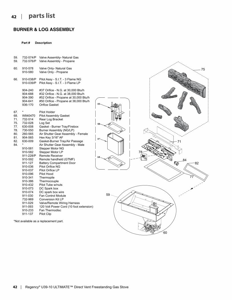
42 | Regency® U39-10 ULTIMATE™ Direct Vent Freestanding Gas Stove
| 42 parts list
84
78
82
77
71
60
75
59
BURNER & LOG ASSEMBLY
59. 732-574/P Valve Assembly- Natural Gas59. 732-576/P Valve Assembly - Propane
60. 910-578 Valve Only- Natural Gas 910-580 Valve Only - Propane
66. 910-038/P Pilot Assy - S.I.T. - 3 Flame NG 910-039/P Pilot Assy - S.I.T. - 3 Flame LP
904-240 #37 Orifice - N.G. at 30,000 Btu/h 904-688 #32 Orifice - N.G. at 38,000 Btu/h 904-390 #52 Orifice - Propane at 30,000 Btu/h 904-641 #50 Orifice - Propane at 38,000 Btu/h 936-170 Orifice Gasket
67. * Pilot Holder68. W840470 Pilot Assembly Gasket71. 732-514 Rear Log Bracket75. 732-028 Log Set77. 630-008 Gasket - Burner Tray/Firebox78. 730-550 Burner Assembly (NG/LP)80. 260-565 Air Shutter Gear Assembly - Female81. 904-565 Hex Key 3/16" AF82. 630-009 Gasket-Burner Tray/Air Passage84. * Air Shutter Gear Assembly - Male 910-581 Stepper Motor NG 910-582 Stepper Motor LP 911-228/P Remote Receiver 910-592 Remote handheld (GTMF) 911-127 Battery Compartment Door 910-036 Pilot Orifice NG 910-037 Pilot Orifice LP 910-096 Pilot Hood 910-341 Thermopile 910-386 Thermocouple 910-432 Pilot Tube w/nuts 910-073 DC Spark box 910-074 DC spark box wire 911-030 Fan Control Module 732-969 Conversion Kit LP 911-029 Valve/Remote Wiring Harness 911-093 120 Volt Power Cord (10 foot extension) 910-233 Fan Thermodisc 911-137 Pilot Clip
*Not available as a replacement part.
Part # Description

Regency® U39-10 ULTIMATE™ Direct Vent Freestanding Gas Stove | 43
43| parts list
DOOR ASSEMBLY
Part # Description
209
732-943 Black Wrap Door - Complete 732-944 Brushed Nickel Wrap Door - Complete
101. 732-570 Door Gasket Kit 105. * Ceramic Paper107. 936-243 Glass Gasket111. * Door Frame Fibre Paper
208. 940-325/P Wrap Glass209. 732-020 Door Mounting Bracket
*Not available as a replacement part.
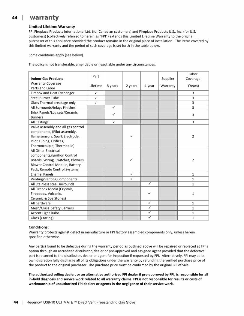
44 | Regency® U39-10 ULTIMATE™ Direct Vent Freestanding Gas Stove
| 44 warranty
Revision Date: February 2019 Regency Gas Products Warranty
Limited Lifetime Warranty FPI Fireplace Products International Ltd. (for Canadian customers) and Fireplace Products U.S., Inc. (for U.S. customers) (collectively referred to herein as “FPI”) extends this Limited Lifetime Warranty to the original purchaser of this appliance provided the product remains in the original place of installation. The items covered by this limited warranty and the period of such coverage is set forth in the table below. Some conditions apply (see below). The policy is not transferable, amendable or negotiable under any circumstances.
Indoor Gas Products Part Supplier Labor
Coverage Warranty Coverage Parts and Labor Lifetime 5 years 2 years 1 year Warranty (Years)
Firebox and Heat Exchanger 3 Steel Burner Tube 3 Glass Thermal breakage only 3 All Surrounds/Inlays Finishes 3 Brick Panels/Log sets/Ceramic Burners 3
All Castings 3 Valve assembly and all gas control components, (Pilot assembly, flame sensors, Spark Electrode, Pilot Tubing, Orifices, Thermocouple, Thermopile)
2
All Other Electrical components,(Ignition Control Boards, Wiring, Switches, Blowers, Blower Control Module, Battery Pack, Remote Control Systems)
2
Enamel Panels 1 Venting/Venting Components 1 All Stainless steel surrounds 1 All Firebox Media (Crystals, Firebeads, Volcanic, Ceramic & Spa Stones)
1
All hardware 1 Mesh/Glass Safety Barriers 1 Accent Light Bulbs 1 Glass (Crazing) 1
Conditions: Warranty protects against defect in manufacture or FPI factory assembled components only, unless herein specified otherwise. Any part(s) found to be defective during the warranty period as outlined above will be repaired or replaced at FPI’s option through an accredited distributor, dealer or pre-approved and assigned agent provided that the defective part is returned to the distributor, dealer or agent for inspection if requested by FPI. Alternatively, FPI may at its own discretion fully discharge all of its obligations under the warranty by refunding the verified purchase price of the product to the original purchaser. The purchase price must be confirmed by the original Bill of Sale. The authorized selling dealer, or an alternative authorized FPI dealer if pre-approved by FPI, is responsible for all in-field diagnosis and service work related to all warranty claims. FPI is not responsible for results or costs of workmanship of unauthorized FPI dealers or agents in the negligence of their service work.

Regency® U39-10 ULTIMATE™ Direct Vent Freestanding Gas Stove | 45
45| warranty
Revision Date: February 2019 Regency Gas Products Warranty
At all times FPI reserves the right to inspect reported complaints on location in the field claimed to be defective prior to processing or authorizing of any claim. Failure to allow this upon request will void the warranty. All warranty claims must be submitted by the dealer servicing the claim, including a copy of the Bill of Sale (proof of purchase by you). All claims must be complete and provide full details as requested by FPI to receive consideration for evaluation. Incomplete claims may be rejected. Unit must be installed according to all manufacturers’ instructions as per the manual. All Local and National required codes must be met. The installer is responsible to ensure the unit is operating as designed at the time of installation. The original purchaser is responsible for annual maintenance of the unit, as outlined in the owner’s manual. As outlined below, the warranty may be voided due to problems caused by lack of maintenance. Repair/replacement parts purchased by the consumer from FPI after the original coverage has expired on the unit will carry a 90 day warranty, valid with a receipt only. Any item shown to be defective will be repaired or replaced at our discretion. No labor coverage is included with these parts Exclusions: This Limited Lifetime Warranty does not extend to paint, rust or corrosion of any kind due to a lack of maintenance or improper venting, combustion air provision, corrosive chemicals (i.e. chlorine, salt, air, etc.), door or glass gasketing. Malfunction, damage or performance based issues as a result of environmental conditions, location, chemical damages, downdrafts, installation error, installation by an unqualified installer, incorrect chimney components (including but not limited to cap size or type), operator error, abuse, misuse, use of improper fuels , lack of regular maintenance and upkeep, acts of God, weather related problems from hurricanes, tornados, earthquakes, floods, lightning strikes/bolts or acts of terrorism or war, which result in malfunction of the appliance are not covered under the terms of this Limited Lifetime Warranty. FPI has no obligation to enhance or modify any unit once manufactured (i.e. as products evolve, field modifications or upgrades will not be performed on existing appliances). This warranty does not cover dealer travel costs for diagnostic or service work. All labor rates paid to authorized dealers are subsidized, pre-determined rates. Dealers may charge homeowner for travel and additional time beyond their subsidy. Any unit showing signs of neglect or misuse will not be covered under the terms of this warranty policy and may void this warranty. This includes units with rusted or corroded fireboxes which have not been reported as rusted or corroded within three (3) months of installation/purchase. Units which show evidence of being operated while damaged, or with problems known to the purchaser and causing further damages will void this warranty. Units where the serial no. has been altered, deleted, removed or made illegible will void this warranty. Minor movement, expansion and contraction of the steel is normal and is not covered under the terms of this warranty. FPI is not liable for the removal or replacement of facings or finishing in order to repair or replace any appliance in the field. Freight damages for products or parts are not covered under the terms of the warranty. Products made or provided by other manufacturers and used in conjunction with the FPI appliance without prior authorization from FPI may void this warranty.

46 | Regency® U39-10 ULTIMATE™ Direct Vent Freestanding Gas Stove
| 46 warranty
Revision Date: February 2019 Regency Gas Products Warranty
Limitations of Liability: The original purchaser’s exclusive remedy under this warranty, and FPI’s sole obligation under this warranty, express or implied, in contract or in tort, shall be limited to replacement, repair, or refund, as outlined above. IN NO EVENT WILL FPI BE LIABLE UNDER THIS WARRANTY FOR ANY INCIDENTAL OR CONSEQUENTIAL COMMERCIAL DAMAGES OR DAMAGES TO PROPERTY. TO THE EXTENT PERMITTED BY APPLICABLE LAW, FPI MAKES NO EXPRESS WARRANTIES OTHER THAN THE WARRANTY SPECIFIED HEREIN. THE DURATION OF ANY IMPLIED WARRANTY IS LIMITED TO DURATION OF THE EXPRESSED WARRANTY SPECIFIED ABOVE. IF IMPLIED WARRANTIES CANNOT BE DISCLAIMED, THEN SUCH WARRANTIES ARE LIMITED IN DURATION TO THE DURATION OF THIS WARRANTY. Some U.S. states do not allow limitations on how long an implied warranty lasts, or allow exclusion or limitation of incidental or consequential damages, so the above limitations or exclusions may not apply to you. Customers located outside the U.S. should consult their local, provincial or national legal codes for additional terms which may be applicable to this warranty. How to Obtain Warranty Service: Customers should contact the authorized selling dealer to obtain warranty service. In the event the authorized selling dealer is unable to provide warranty service, please contact FPI by mail at the address listed below. Please include a brief description of the problem and your address, email and telephone contact information. A representative will contact you to make arrangements for an inspection and/or warranty service. Canadian Warrantor: FPI Fireplace Products International Ltd. 6988 Venture St. Delta, British Columbia Canada, V4G 1H4
U.S. Warrantor: Fireplace Products U.S., Inc. PO Box 2189 PMB 125 Blaine, WA United States, 98231
Or contact the Regency Customer Care Centre at 1-800-442-7432 (phone) / 604-946-4349 (fax) Product Registration and Customer Support: Thank you for choosing a Regency Fireplace. Regency strives to be a world leader in the design, manufacture, and marketing of hearth products. To provide the best support for your product, we request that you complete a product registration form at http://www.regency-fire.com/Customer-Care/Warranty-Registration.aspx within ninety (90) days of purchase.

Regency® U39-10 ULTIMATE™ Direct Vent Freestanding Gas Stove | 47
47| warranty
Product Registration and Customer Support:
Thank you for choosing a Regency Fireplace. Regency strives to be a world leader in the design, manufacture, and marketing of hearth products. To provide the best support for your product, we request that you complete a product registration form found on our Web Site under Customer Care within ninety (90) days of purchase.
For purchases made in CANADA or the UNITED STATES: http://www.regency-fire.com/Customer-Care/Warranty-Registration.aspx
For purchases made in AUSTRALIA: http://www.regency-fire.com.au/Customer-Care/Warranty-Registration.aspx
You may also complete the warranty registration form below to register your Regency Fireplace Product and mail and/or fax it back to us, and we will register the warranty for you. It is important you provide us with all the information below in order for us to serve you better.
Warranty Registration Form (or Register online immediately at the above Web Site):
Warranty Details
Serial Number (required):
Purchase Date (required) (mm/dd/yyyy):
Product Details
Product Model (required):
Dealer Details
Dealer Name (required):
Dealer Address:
Dealer Phone #:
Installer:
Date Installed (mm/dd/yyyy):
Your Contact Details (required)
Name:
Address:
Phone:
Email:
For purchases made in CANADA:
FPI Fireplace Products International Ltd. 6988 Venture St. Delta, British Columbia Canada, V4G 1H4
For purchases made in the UNITED STATES:
Fireplace Products U.S., Inc. PO Box 2189 PMB 125 Blaine, WA United States, 98231
Phone: 604-946-5155 Fax: 604-946-4349
Phone: 604-946-5155 Fax: 604-946-4349
For purchases made in AUSTRALIA:
Fireplace Products Australia Pty Ltd 1- 3 Conquest Way Hallam, VIC Australia, 3803
Phone: +61 3 9799 7277 Fax: +61 3 9799 7822
For fireplace care and tips and answers to most common questions please visit our Customer Care section on our Web Site. Please feel free to contact your selling dealer if you have any questions about your Regency product.

Regency® U39-10 ULTIMATE™ Direct Vent Freestanding Gas Stove | 49
49| notes

50 | Regency® U39-10 ULTIMATE™ Direct Vent Freestanding Gas Stove
| 50 notes


Printed in CanadaRegency® is a trademark of FPI Fireplace Products International Ltd.© Copyright 2019, FPI Fireplace Products International Ltd. All rights reserved.
U38-39 Video
Installer: Please complete the following information
Dealer Name & Address: ______________________________________________
___________________________________________________________________
Installer: ___________________________________________________________
Phone #: ___________________________________________________________
Date Installed: ______________________________________________________
Serial No.: __________________________________________________________