Ultimate Commercial Equipment Room Control - · PDF file• Multiple pool control for 1, 2...
4
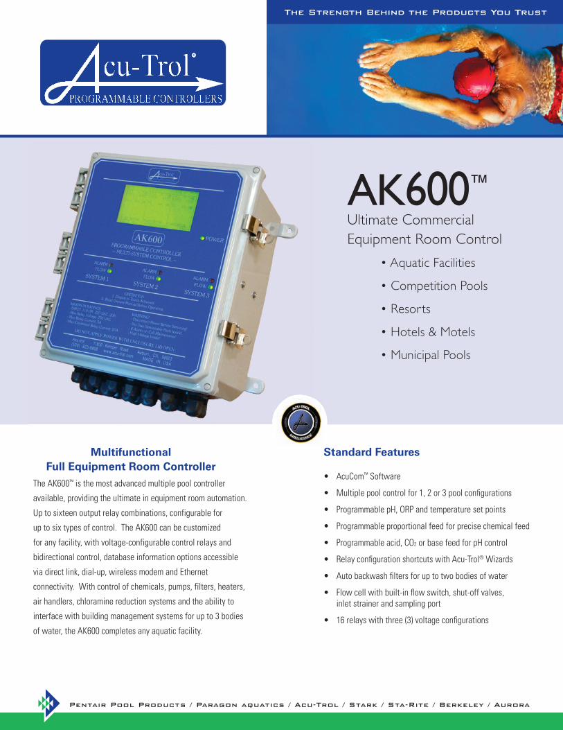
AcuCom • ™ Software Multiple pool control for 1, 2 or 3 pool configurations • Programmable pH, ORP and temperature set points • Programmable proportional feed for precise chemical feed • Programmable acid, CO • 2 or base feed for pH control Relay configuration shortcuts with Acu-Trol • ® Wizards Auto backwash filters for up to two bodies of water • Flow cell with built-in flow switch, shut-off valves, • inlet strainer and sampling port 16 relays with three (3) voltage configurations • The AK600 ™ is the most advanced multiple pool controller available, providing the ultimate in equipment room automation. Up to sixteen output relay combinations, configurable for up to six types of control. The AK600 can be customized for any facility, with voltage-configurable control relays and bidirectional control, database information options accessible via direct link, dial-up, wireless modem and Ethernet connectivity. With control of chemicals, pumps, filters, heaters, air handlers, chloramine reduction systems and the ability to interface with building management systems for up to 3 bodies of water, the AK600 completes any aquatic facility. Multifunctional Full Equipment Room Controller AK 600 ™ Ultimate Commercial Equipment Room Control • Aquatic Facilities • Competition Pools • Resorts • Hotels & Motels • Municipal Pools Standard Features The Strength Behind the Products You Trust
-
Upload
truongkhue -
Category
Documents
-
view
217 -
download
2
Transcript of Ultimate Commercial Equipment Room Control - · PDF file• Multiple pool control for 1, 2...
AcuCom• ™ Software
Multiple pool control for 1, 2 or 3 pool confi gurations•
Programmable pH, ORP and temperature set points•
Programmable proportional feed for precise chemical feed•
Programmable acid, CO• 2 or base feed for pH control
Relay confi guration shortcuts with Acu-Trol• ® Wizards
Auto backwash fi lters for up to two bodies of water•
Flow cell with built-in fl ow switch, shut-off valves, • inlet strainer and sampling port
16 relays with three (3) voltage confi gurations•
The AK600™ is the most advanced multiple pool controller
available, providing the ultimate in equipment room automation.
Up to sixteen output relay combinations, configurable for
up to six types of control. The AK600 can be customized
for any facility, with voltage-configurable control relays and
bidirectional control, database information options accessible
via direct link, dial-up, wireless modem and Ethernet
connectivity. With control of chemicals, pumps, filters, heaters,
air handlers, chloramine reduction systems and the ability to
interface with building management systems for up to 3 bodies
of water, the AK600 completes any aquatic facility.
Multifunctional Full Equipment Room Controller
AK600™
Ultimate Commercial Equipment Room Control
• Aquatic Facilities
• Competition Pools
• Resorts
• Hotels & Motels
• Municipal Pools
Standard Features
The Strength Behind the Products You Trust
ProgrammabilitypH, ORP and temperature set point• ORP calibration• ORP super-chlorination • PPM control• Temperature calibration• Proportional feed• Feeder ON and OFF times• Mix times and cycle times• Overfeed lock out times• Acid/Base feed pH control • Auto backwash fi lter settings• Water level • Auto probe clean• 16 pager numbers• 7 passwords•
AlarmspH Alarms •
pH set point ± percentages Overfeed disables pH feed Flow switch disables pH feed High pH disables feed
ORP Alarms • ORP set point ± percentages Overfeed disables Disinfectant feed Flow switch disables feed
Sensors• The AK600™ sensors are capable of measuring ORP, pH, free chlorine, conductivity, temperature, fl ow rate and pressure.
Flow Cell• The AK1200™ offers inlet and outlet valves for sensor protection and third outlet for ease of water sampling.
Relays• Customized relay control for up to 96 combinations.
Colorimetric Compatible• Compatible with the AKColor™ Colorimetric PPM sensing measurement system for free and total chlorine.
Readings• The AK600 displays the Puckorius, Langelier or Ryzner indexes and differential infl uent and effl uent pressure.
Data Recording • In the absence of power, the AK600 will retain programming information, calibration, and recorded data.
Alarms• Alarms are activated by sensor measurements and will communicate at two hour until alarm is cleared.
Communication• The AK600 communicates using the AcuCom™ and AcuManage II™. Software packages provides wireless communication with modem modules.
Security • Password protected allows limited access.
AcuManage II• ™ Website Notifi cation alarms and sensor readings AcuManage II available via wireless or AcuPort™ communication only
AcuPort• ™ Connectivity Ethernet, WiFi or RS422/485
Input/Output Modules• AK245™ Quad 4-20mA/O-5VDC output AK250™ Quad 4-20mA/0-5VDC input
Acu-Trol• ® Absorb It™ Controls the Acu-Trol’s Absorb It system for the use of CO2 for optimal pH and alkalinity control
AKColor• ™ Sensor The AKColor colorimetric sensor system measures PPM of free chlorine with the DPD (N, N-DIETHYL-P-PHE NYLENEDIAMINE) test
Infl uent/Effl uent Pressure Sensor• Pressure information for control of an automatic backwash
Optical Level Sensor• Measurement and automatic control of water level
Digital Flow Sensor• Displays fl ow rate in gallons per minute
Conductivity Sensor• Measurement of water TDS
Premounting • Mounted on easy to install polypropylene predrilled board
Serial Printer• On site printer capability with separate module
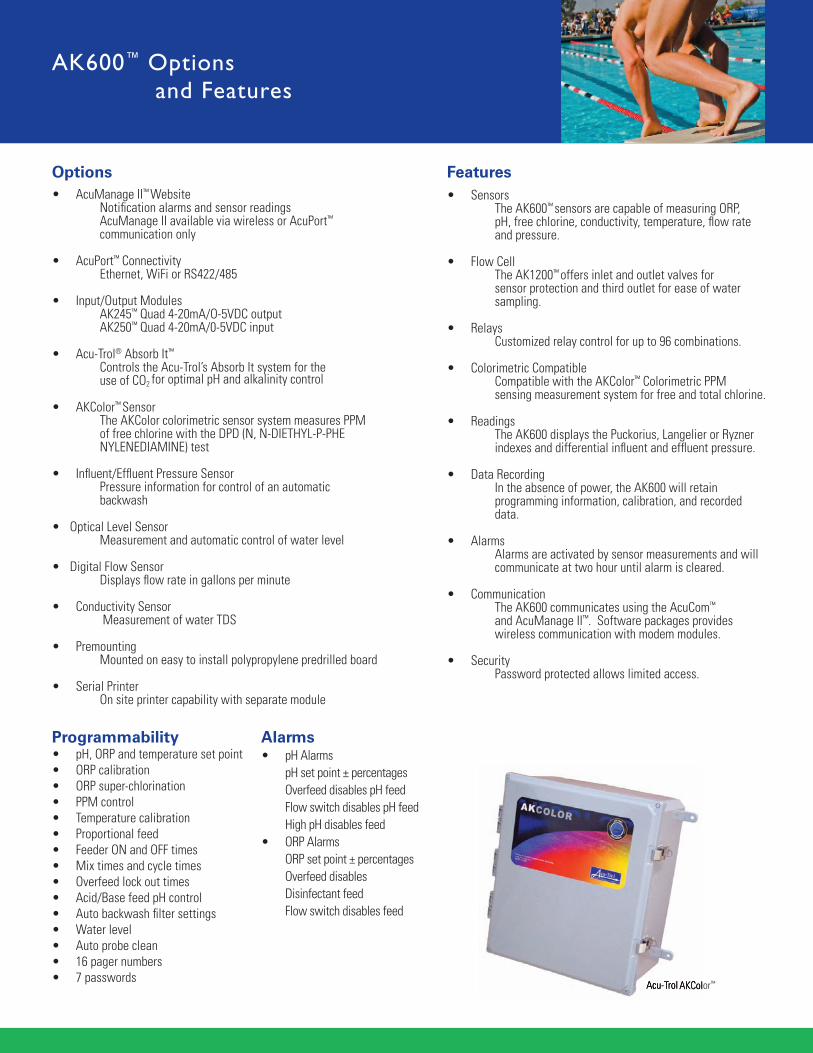
Acu-Trol AKColor™
AK600™ Options and Features
Acu-Trol AKColor
Options Features
AcuPort™ AcuCom™ SoftwareAcuManage II™
AcuManage.net Login
http://www.acumanage.net/[10/15/2008 1:04:30 PM]
Username:
Password:
Username and Password are case sensitive and may contain upper and lower case letters. Click here for more information.
Click here for Original AcuManage website.
LOGIN
AK110 Data
http://www.acumanage.net/ak110data/displayAllAK110/155[10/15/2008 2:00:51 PM]
10/15/08, 16:07:18 Off On Off 7.48 00:45:36 765 00:00:00 23.9 00:00:00 7.50 750 29152 784426 30414
10/15/08, 15:37:21 Off On Off 7.48 00:45:36 766 00:00:00 23.9 00:00:00 7.50 750 29152 784189 30413
10/15/08, 15:07:19 Off On Off 7.48 00:45:36 767 00:00:00 23.7 00:00:00 7.50 750 29152 783952 30412
10/15/08, 14:37:20 Off On Off 7.48 00:45:36 768 00:00:00 23.5 00:00:00 7.50 750 29152 783715 30411
10/15/08, 14:07:21 Off On Off 7.49 00:45:36 768 00:00:00 23.3 00:00:00 7.50 750 29152 783477 30410
10/15/08, 13:37:17 Off On Off 7.49 00:45:36 769 00:00:00 23.1 00:00:00 7.50 750 29152 783239 30409
10/15/08, 13:07:23 Off On Off 7.49 00:45:36 770 00:00:00 23.0 00:00:00 7.50 750 29152 783001 30408
10/15/08, 12:37:23 Off On Off 7.49 00:45:36 770 00:00:00 22.8 00:00:00 7.50 750 29152 782763 30407
10/15/08, 12:07:21 Off On Off 7.50 00:45:36 770 00:00:00 22.6 00:00:00 7.50 750 29152 782525 30406
10/15/08, 11:37:17 Off On Off 7.50 00:45:36 771 00:00:00 22.4 00:00:00 7.50 750 29152 782287 30405
10/15/08, 10:37:18 Off On Off 7.50 00:45:36 773 00:00:00 22.2 00:00:00 7.50 750 29152 782048 30403
10/15/08, 10:07:18 Off On Off 7.50 00:45:36 773 00:00:00 22.1 00:00:00 7.50 750 29152 781810 30402
10/15/08, 09:37:19 Off On Off 7.51 00:45:36 773 00:00:00 22.1 00:00:00 7.50 750 29152 781572 30401
10/15/08, 09:07:18 Off On Off 7.51 00:45:00 774 00:00:00 22.0 00:00:00 7.50 750 29152 781334 30400
10/15/08, 08:37:16 Off On Off 7.51 00:43:50 775 00:00:00 22.0 00:00:00 7.50 750 29152 781096 30399
10/15/08, 08:07:18 Off On Off 7.51 00:41:40 775 00:00:00 22.0 00:00:00 7.50 750 29152 780858 30398
10/15/08, 07:37:18 Off On Off 7.51 00:39:28 775 00:00:00 22.0 00:00:00 7.50 750 29152 780620 30397
10/15/08, 07:07:25 Off On Off 7.51 00:37:38 774 00:00:00 22.1 00:00:00 7.50 750 29152 780382 30396
10/15/08, 06:37:18 Off On Off 7.51 00:35:26 774 00:00:00 22.2 00:00:00 7.50 750 29152 780144 30395
10/15/08, 06:07:17 Off On Off 7.51 00:33:36 773 00:00:00 22.2 00:00:00 7.50 750 29152 779906 30394
10/15/08, 05:37:17 Off On Off 7.51 00:31:24 772 00:00:00 22.3 00:00:00 7.50 750 29152 779668 30393
10/15/08, 05:07:18 Off On Off 7.52 00:28:32 772 00:00:00 22.4 00:00:00 7.50 750 29152 779430 30392
10/15/08, 04:37:18 Off On Off 7.51 00:26:40 771 00:00:00 22.4 00:00:00 7.50 750 29152 779192 30391
10/15/08, 04:07:18 Off On Off 7.52 00:24:06 770 00:00:00 22.4 00:00:00 7.50 750 29152 778953 30390
10/15/08, 03:37:19 Off On Off 7.51 00:22:16 770 00:00:00 22.5 00:00:00 7.50 750 29152 778715 30389
« Previous 2 3 4 5 6 7 8 9 ... 220 221 Next » Reports | Day Plot | Week Plot |Month Plot | Export AK110 Data
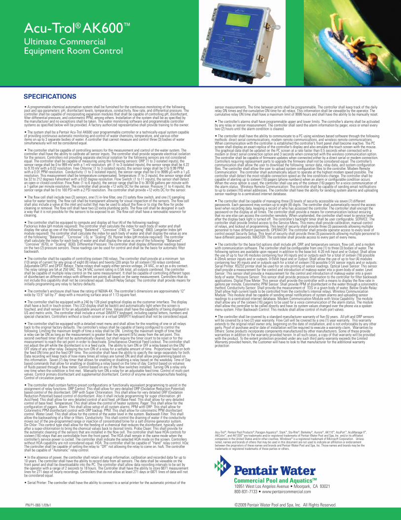
Access essential water chemistry information instantly. AcuCom™ and AcuManage II™ provide interactive control of multiple-bodies of water with the click of a mouse from any PC. View multiple locations at once and manage water chemistry without unnecessary service calls. With an optional wireless modem or the AcuPort™, the data management system goes mobile and completes the AK110™ equipment room package.
Remote access from AcuCom software packages • (requires optional communication modules)
System will call out alarm conditions to • 4 pager numbers or e-mail addresses
Over 30 days of data can be internally stored in two (2) hour • intervals or 15 days in one (1) hour intervals
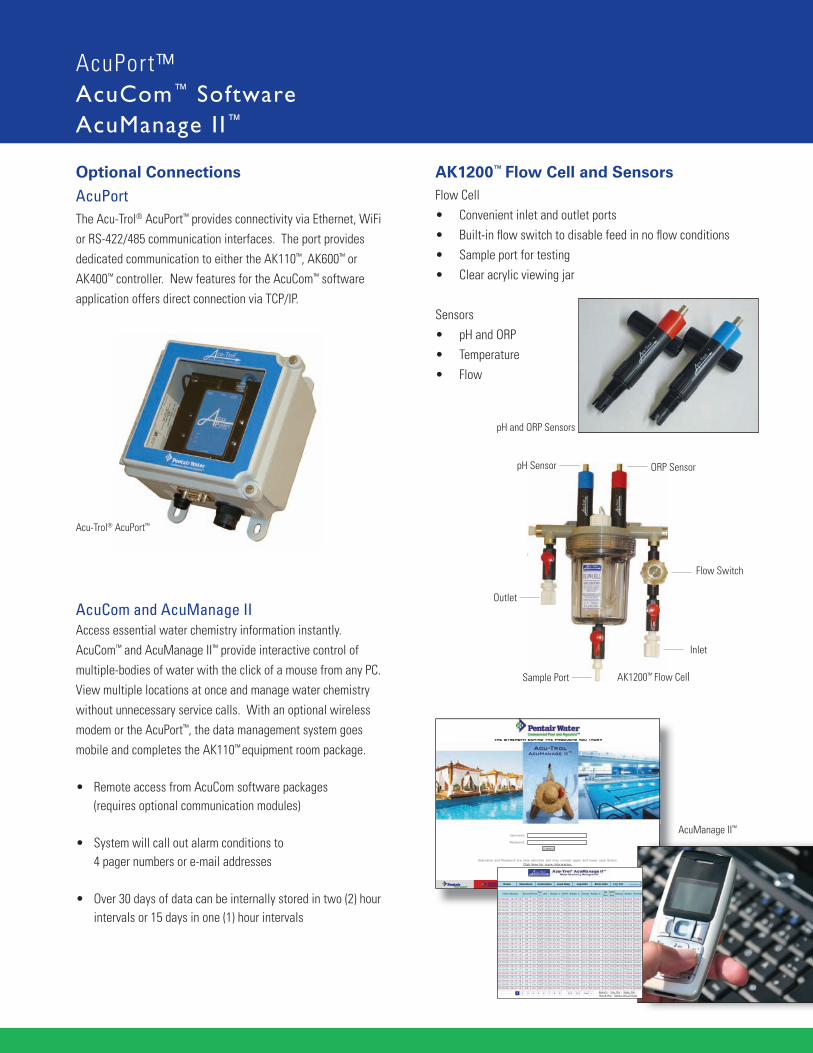
Flow CellConvenient inlet and outlet ports• Built-in fl ow switch to disable feed in no fl ow conditions• Sample port for testing• Clear acrylic viewing jar•
Sensors
pH and ORP • Temperature• Flow•
AK1200™ Flow Cell and Sensors
pH Sensor ORP Sensor
Outlet
Inlet
Flow Switch
Sample Port
The Acu-Trol® AcuPort™ provides connectivity via Ethernet, WiFi or RS-422/485 communication interfaces. The port provides dedicated communication to either the AK110™, AK600™ or AK400™ controller. New features for the AcuCom™ software application offers direct connection via TCP/IP.
Acu-Trol® AcuPort™
Optional Connections
AcuManage II™
AcuPort
AcuCom and AcuManage II
AK1200™ Flow Cell
pH and ORP Sensors
sensor measurements. The time between prints shall be programmable. The controller shall keep track of the daily relay ON times and the cumulative ON time for all relays. This information shall be viewable by the operator. The cumulative relay ON time shall have a maximum limit of 9999 hours and shall have the ability to be manually reset.
• The controller’s alarms shall have programmable upper and lower limits. The controller’s alarms shall be activated by any relay or sensor measurement. The controller shall send the alarm information by pager, voice or email every two (2) hours until the alarm condition is cleared. • The controller shall have the ability to communicate to a PC using windows based software through the following methods: direct serial communications, modem remote communications, and wireless remote communications. When communication with the controller is established the controller’s front panel shall become inactive. The PC screen shall display an exact replica of the controller’s display and also emulate the touch screen with the mouse. The graphical data shall be updated on the PC screen at a rate faster than 0.5 seconds when connected with a modem or direct serial connection option and 3 seconds when connected with the wireless communication option. The controller shall be capable of fi rmware updates when connected either by a direct serial or modem connection. Controllers requiring replacement parts to upgrade the fi rmware shall not be considered equal. The controller’s communication shall allow the user to download the following: sensor data, relay data, and system confi guration fi les. The controller shall allow the user to upload system confi guration fi les to the controller. Modem Remote Communication: The controller shall automatically adjust to operate at the highest modem speed possible. The controller shall detect the most reliable connection speed as the line conditions change. The controller shall be capable of alerting up to sixteen (16) pagers (phone numbers) when an alarm or confi gurable condition occurs. When the voice option is used, the controller shall use any of the sixteen (16) pagers for a voice communication of the alarm status. Wireless Remote Communication: The controller shall be capable of sending email notifi cations to up to sixteen (16) email addresses. The controller shall have the ability for sending system alarms and uploading sensor readings to a centralized internet database.
• The controller shall be capable of managing three (3) levels of security accessible via seven (7) different passwords. Each password may contain up to eight (8) digits. The controller shall automatically record the access level when recording data, keeping a record of who has accessed the controller. The controller shall encrypt the password on the display at all times. The controller shall provide a means for communication lockout ensuring that no one else can access the controller remotely. When unattended, the controller shall reset to service level after the display back light is turned off. The controller’s backlight timer shall be user confi gurable. SERVICE: The controller shall provide limited access to the Service Menu. This menu shall provide calibration, manual control of relays, and lockout of programming. This level of security shall provide three (3) passwords allowing multiple personnel to have different passwords. OPERATOR: The controller shall provide operator access to every level of control except Security Setup. This level of security shall provide three (3) passwords allowing multiple personnel to have different passwords. MASTER: The controller shall provide access to every part of every menu.
• The controller for the base bid options shall include pH, ORP, and temperature sensors, fl ow cell, and a modem with communication software. The controller shall be confi gurable from one (1) to three (3) bodies of water. The following options are available upon request in addition to the base bid. 4-20 mA Input and or Output: Shall allow the use of up to four (4) modules containing four (4) inputs and or outputs each for a total of sixteen (16) possible 4-20mA sensor inputs and or outputs. 0-5Volt Input and or Output: Shall allow the use of up to four (4) modules containing four (4) inputs and or outputs each for a total of sixteen (16) possible 0-5V sensor inputs and or outputs. Serial Printer: RS232 printer shall be used for on site printing of sensor readings. Optical Level Sensor: This sensor shall provide a measurement for the control and introduction of makeup water into a given body of water. Level Sensor: This sensor shall provide a measurement for the control and introduction of makeup water into a given body of water. Pressure Sensor: This sensor shall provide pressure information to the controller for fi lter backwash applications. Digital Flow Meter: This sensor shall provide the controller with a means to display the fl ow rate in gallons per minute. Colorimetric PPM Sensor: Shall provide PPM of disinfectant in the water through a colorimetric method. Conductivity Sensor: Shall provide the measurement of TDS in a given body of water. Below Grade Relay: Shall allow high current loads to be controlled from the controller’s internal relays. Wireless Communication Module: This module shall be capable of sending email notifi cations of system alarms and uploading sensor readings to a centralized internet database. Modem Communication Module with Voice Capability: The module shall allow any of the sixteen (16) pagers to be used for a voice communication of the alarm status. The module shall allow the controller to be called directly and have its system values changed over the phone via a spoken menu system. Filter Backwash Control: This module shall allow control of multi-port valves.
• The controller shall be covered by a standard manufacturer warranty of fi ve (5) years. All pH and ORP sensors will be covered by a two (2) year warranty. Flow Cell will be covered by a one (1) year warranty. This warranty extends to the original retail owner only, beginning on the date of installation, and is not enforceable by any other party. Proof of purchase and/or date of installation will be required to execute a warranty claim. Warranties by Others: Some products incorporate components manufactured by other manufacturers. Some of these provide warranties in addition to the warranty provided herein. In all such cases, a copy of that warranty will be provided with the product. To the extent protection provided under any such third party warranty exceeds the Limited Warranty provided herein, the Customer will have to look to that manufacturer for the additional warranty protection
• A programmable chemical automation system shall be furnished for the continuous monitoring of the following pool and spa parameters: pH, disinfectant levels, temperature, conductivity, fl ow rate, and differential pressure. The controller shall be capable of incorporating expansion modules that shall be capable of controlling pH, disinfectant, fi lter differential pressure, and colorimetric PPM, among others. Installation of the system shall be as specifi ed by the manufacturer and no exceptions shall be taken. The water monitoring software and programmable controller systems as specifi ed below will be provided. A factory authorized representative shall provide training to the owner.
• The system shall be a Pentair Acu-Trol AK600 user programmable controller or a technically equal system capable of providing continuous automatic monitoring and control of water chemistry, temperature, and various other items on up to 3 separate bodies of water. A controller that cannot measure and control three (3) bodies of water simultaneously will not be considered equal.
• The controller shall be capable of controlling sensors for the measurement and control of the water system. The controller shall have the ability to calibrate all sensor inputs. The controller shall provide separate electrical isolation for the sensors. Controllers not providing separate electrical isolation for the following sensors are not considered equal. The controller shall be capable of measuring using the following sensors: ORP: (1 to 3 isolated inputs), the sensor range shall be 0 to 999 mV with a 1 mV resolution. pH: (1 to 3 isolated inputs), the sensor range shall be 4.22 to 9.70 mV with a 0.02 resolution. Free Chlorine: (1 to 3 isolated inputs), the sensor range shall be 0 to 9.99 PPM with a 0.01 PPM resolution. Conductivity: (1 to 3 isolated inputs), the sensor range shall be 0 to 9999 µS with a 1 µS resolution. This measurement shall be temperature compensated. Temperature: (1 to 3 inputs), the sensor range shall be 32 to 212 degrees Fahrenheit with a 0.02 degree resolution. Flow Switch: (1 to 11 inputs), the sensor shall detect an open or closed condition. Flow Rate: (1 to 6 inputs), the sensor range shall be 0 to 36166 gallons per minute with a 1 gallon per minute resolution. The controller shall provide +12 volts DC for the sensor. Pressure: (1 to 4 inputs), the sensor range shall be 0 to 100 PSI with a 2 PSI resolution. The controller shall provide +12 volts DC for the sensor.
• The fl ow cell shall include two (2) sensors, one (1) in-line fi lter, one (1) safety fl ow switch, and one (1) sampling valve for water testing. The fl ow cell shall be transparent allowing for visual inspection of the sensors. The fl ow cell shall also include a valve at the inlet and outlet that may be used to adjust the fl ow or to stop the fl ow for probe cleaning or removal. The fl ow cell shall have two (2) extra plumbing ports. The fl ow cell shall be designed in such a way that it is not possible for the sensors to be exposed to air. The fl ow cell shall have a removable reservoir for cleaning.
• The controller shall be equipped to compute and display all four (4) of the following readings:Puckorius Index (pH module required): The controller shall calculate the index for each body of water and shall display the value as one of the following: “Balanced”, “Corrosive” (740), or “Scaling” (660). Langelier Index (pH module required): The controller shall calculate the index for each body of water and shall display the value as one of the following: “Balanced”, “Corrosive” (-5), or “Scaling” (5). Rysner Index (pH module required): The controller shall calculate the index for each body of water and shall display the value as one of the following: “Balanced”, “Corrosive” (670), or “Scaling” (630). Differential Pressure: The controller shall display differential readings based on the two (2) pressure sensors. These readings can be used for control and shall be the basis for automatic fi lter backwash.
• The controller shall be capable of controlling sixteen (16) relays. The controller shall provide at a minimum ten (10) amps of current for any group of eight (8) relays and twenty (20) amps for all sixteen (16) relays combined. Adjustable DPST and DPDT Relays: These relays shall supply either service voltage, 24 VAC, or act as a dry contact. The relay ratings are 5A at 250 VAC. The 24 VAC current rating is 0.5A total, all outputs combined. The controller shall be capable of multiple relay control on the same measurement. It shall be capable of controlling different types of disinfectant on different relays with different set points all based on the same measurement. Controllers that do not include this capability shall not be considered equal. Default Relay Setups: The controller shall provide means for initially programming any relay to factory defaults.
• The controller’s enclosure shall have the rating of NEMA 4X. The controller’s dimensions are approximately 12” wide by 13.5” tall by 7” deep with a mounting surface area of 1.13 square feet.
• The controller shall be equipped with a 240 by 128 pixel graphical display as the customer interface. The display shall have a built in touch-screen. This LCD display shall be backlit and automatically light when the screen is touched, and shall remain lit for an adjustable amount of time. Values shall have the capability of being displayed in US and metric units. The controller shall include a virtual QWERTY keyboard, including capital letters, numbers and special characters. Controllers without a touch-screen or a virtual QWERTY keyboard shall not be considered equal.
• The controller shall be equipped with a detailed reset menu and shall allow for the resetting of one or all relays back to the original factory defaults. The controller’s relays shall be capable of being confi gured to control the following: Limiting the maximum length of time a relay shall be ON. Limiting the maximum length of time that a relay can be ON as long as the measurement is greater than fi ve percent (5%) away from the set point. This second overfeed timer shall not be automatically cleared, but shall require the timer count to be reset or for the measurement to reach the set point in order to deactivate. Simultaneous Chemical Feed Lockout. The controller shall not adjust the pH while the disinfectant is in a feed cycle. The ability to turn ON or OFF a relay based on the ON/OFF state of any other relay. Delaying the turn ON of a relay for a settable amount of time. Proportional feed on both the feed ON time and the feed OFF time. The controller shall have the ability to specify the range separately for both. Data recording will keep track of how many times all relays are turned ON and shall allow programming based on this information. Seven (7) day timer that allows for enabling or disabling a relay based on the weekday. Time of Day based commands that allow for enabling or disabling a relay based on the time of day. Control based on volumes of fl uids passed through a fl ow meter. Control based on any of the fl ow switches installed. Turning ON a relay only one time when the condition is fi rst met. Manually turn ON a relay for an adjustable feed time. Control of multi-port valves. Control primary disinfectant and supplemental disinfectant. Control of enzyme and monopersulfate feeding. Control of circulation pumps.
• The controller shall contain factory-preset confi gurations or functionally equivalent programming to assist in the assignment of relay functions. ORP Control: This shall allow for very detailed ORP (Oxidation Reduction Potential) based control of the disinfectant. ORP with Super Chlorination: This shall allow for very detailed ORP (Oxidation Reduction Potential) based control of disinfectant. Also it shall include programming for super chlorination. pH Acid Feed: This shall allow for very detailed control of acid feed. pH Base Feed: This shall allow for very detailed control of base feed. Temperature: This shall allow the control of heater systems. Pager: This shall allow for the confi guration of pagers. Alarm: This shall allow setup of all system alarms. PPM with ORP: This shall allow for Colorimetric PPM disinfectant control with ORP backup. PPM: This shall allow for colorimetric PPM disinfectant control. Water Level: This shall allow for the control of the water level in the system. Backwash Filter: This shall allow the backwashing of a fi lter or fi lters. Conductivity: This shall control the draining of water if the conductivity moves out of the pre-programmed range or injection of concentrated brine for a salt chlorine generator system. De-Chlor: This control type shall allow for the feeding of a chemical that reduces the disinfectant, typically used after a super-chlorination to bring the chemical values back to desired limits. Probe Clean: This shall provide for the automatic cleaning of the sensors that are installed in the fl ow cell. The controller shall have HOA controls for sixteen (16) relays that are controllable from the front panel. The HOA shall remain in the same mode when the controller’s service power is cycled. The controller shall indicate the selected HOA mode on the screen. Controllers without HOA capability are not considered equal. HOA: The controller shall be capable of “Hand” relay control. hOa: The controller shall be capable of setting the relay to “Off” not allowing the relay to come on. hoA: The controller shall be capable of “Automatic” relay control.
• In the absence of power, the controller shall retain all setup information, calibration and recorded data for up to 10 years. The controller shall have the ability to record data from all sensors. The data shall be viewable on the front panel and shall be downloadable into the PC. The controller shall allow data recording intervals to be set by the operator with a range of 2 seconds to 18 hours. The Controller shall have the ability to store 6871 measurement lines for 271 days of hourly recordings. Controllers that do not allow at least 271 days or 6871 lines of data will not be considered equal.
• Serial Printer: The controller shall have the ability to connect to a serial printer for the automatic printout of the 10951 West Los Angeles Avenue • Moorpark, CA 93021800-831-7133 • www.pentaircommercial.com
©2009 Pentair Water Pool and Spa, Inc. All Rights Reserved.
SPECIFICATIONS
Acu-Trol® AK600™
Ultimate Commercial Equipment Room Control
PN P1-066 1/09v1
Acu-Trol®, Pentair Pool Products®, Paragon Aquatics®, Stark™, Sta-Rite®, Berkeley®, Aurora®, AK110™, AcuPort™, AcuManage II™, AKColor™, and AK1200™ are trademarks and/or registered trademarks of Pentair Water Pool and Spa, Inc. and/or its affi liated companies in the United States and/or other counties. Windows® is a registered trademark of Microsoft Corporation. Unless noted, names and brands of others that may be used in this document are not used to indicate an affi liation or endorsement between the proprietors of these names and brands and Pentair Water Pool and Spa, Inc. Those names and brands may be the trademarks or registered trademarks of those parties or others.