
UltiMate 3000 Pump Series - Thermo Fisher...
202
UltiMate 3000 Series Pump Series Operating Instructions (Original Instructions) Revision: 1.3 Date: November 2011 © 2011 Thermo Fisher Scientific Doc No. 4820.3551
Transcript of UltiMate 3000 Pump Series - Thermo Fisher...

UltiMate 3000 Series
Pump Series
Operating Instructions (Original Instructions)
Revision: 1.3
Date: November 2011
© 2011 Thermo Fisher Scientific Doc No. 4820.3551

UltiMate 3000 Series: Pump Series
Operating Instructions

UltiMate 3000 Series: Pump Series
Operating Instructions Page I
Declaration of Conformity (Original Declaration)
Product: UltiMate 3000 Series Pump Types: LPG-3400AB, LPG-3400M and LPG-3400MB
DGP-3600A, DGP-3600AB, DGP-3600M and DGP-3600MB HPG-3200P
Dionex Softron GmbH herewith declares conformity of the above products with the respective requirements of the following regulations: • Machinery Directive 2006/42/EC • EMC Directive 2004/108/EC The safety of the machinery was evaluated based on the following standard: • EN ISO 12100:2010
Safety of machinery - General principles for design Risk assessment and risk reduction
The electrical safety of the products was evaluated based on the following standard: • DIN EN 61010-1:2002
Safety requirements for electrical equipment for measurement, control and laboratory use, Part 1: General Requirements
The Electromagnetic Compatibility (EMC) of the products was evaluated based on the following standard: • DIN EN 61326: 2006
Electrical equipment for measurement, control and laboratory use EMC Requirements
The protection requirements specified in the low-voltage directive 2006/95/EC are met.
Responsible for the technical CE documentation is the manufacturer (see further down).
This declaration is issued for the manufacturer Dionex Softron GmbH
Part of Thermo Fisher Scientific Inc. Dornierstraße 4
D-82110 Germering by the President, Dr. Peter Jochum. November 2, 2011

UltiMate 3000 Series: Pump Series
Page II Operating Instructions

UltiMate 3000 Series: Pump Series
Operating Instructions Page i
Table of Contents 1 Introduction ................................................................................................................... 1
1.1 How to Use This Manual ........................................................................................... 1 1.2 Safety Information ..................................................................................................... 2
1.2.1 Symbols on the Instrument and in the Manual ................................................. 2 1.2.2 General Safety Precautions ............................................................................... 3 1.2.3 Consignes Générales de Sécurité ...................................................................... 5
1.3 Intended Use .............................................................................................................. 8 1.4 Federal Communications Commission (FCC) Note .................................................. 8
2 Overview ........................................................................................................................ 9
2.1 Unit Description ......................................................................................................... 9 2.2 Operating Principle .................................................................................................. 10 2.3 Pump Configurations ............................................................................................... 12
2.3.1 Overview ........................................................................................................ 12 2.3.2 Biocompatible Pumps ..................................................................................... 14
2.4 Interior Components ................................................................................................ 16 2.5 Front Panel Elements ............................................................................................... 17 2.6 Rear Panel ................................................................................................................ 18
2.6.1 Power Switch .................................................................................................. 19 2.6.2 Fuse Cartridge ................................................................................................ 19 2.6.3 USB Connector ............................................................................................... 19 2.6.4 Pressure (Analog Pressure Output)................................................................. 20 2.6.5 Digital I/O ....................................................................................................... 20 2.6.6 Solvent Rack ................................................................................................... 21
2.7 Fluid Connections .................................................................................................... 21 2.8 Rear Seal Wash System ........................................................................................... 22 2.9 Outlet Unit ............................................................................................................... 23
2.9.1 Inline Filter ..................................................................................................... 23 2.9.2 Mixing Chamber ............................................................................................. 24
2.10 Leak Sensor .......................................................................................................... 25 2.11 Vacuum Degasser ................................................................................................ 25 2.12 Chromeleon Software .......................................................................................... 26 2.13 System Wellness, Predictive Performance, and Diagnostics ............................... 27
3 Installation ................................................................................................................... 29
3.1 Facility Requirements .............................................................................................. 29 3.2 Unpacking ................................................................................................................ 29 3.3 Positioning the Pump in the UltiMate 3000 System ................................................ 30 3.4 Connecting the Pump ............................................................................................... 32
3.4.1 General Information ....................................................................................... 32 3.4.2 Connecting the USB Cable ............................................................................. 32

UltiMate 3000 Series: Pump Series
Page ii Operating Instructions
3.4.3 Connecting the Power Cord ............................................................................ 32 3.4.4 Connecting the Solvent Rack and Digital I/O ................................................ 33
3.5 Setting Up the Pump in Chromeleon ....................................................................... 34 3.5.1 Loading the USB Driver for the Pump ........................................................... 34 3.5.2 Installing the Pump ......................................................................................... 36 3.5.3 Configuring the Pump ..................................................................................... 37
3.5.3.1 Initial Installation ..................................................................................... 37 3.5.3.2 Changing the Configuration Properties ................................................... 44
4 Preparation for Operation (Startup) ........................................................................ 45
4.1 Overview of Actions ................................................................................................ 45 4.2 General Precautions for Connecting Capillaries ...................................................... 46 4.3 Solvent Reservoirs ................................................................................................... 47
4.3.1 General Precautions ........................................................................................ 47 4.3.2 Connecting the Solvent Reservoirs ................................................................. 48
4.4 Connecting the Rear Seal Wash System .................................................................. 49 4.4.1 Filling the Internal Wash Liquid Reservoir .................................................... 50 4.4.2 Installing and Filling the External Wash Liquid Reservoir ............................ 52
4.5 Connecting the Drain Tubing ................................................................................... 53 4.6 Purging the Pump ..................................................................................................... 54
4.6.1 Purging the Pump Manually ........................................................................... 54 4.6.2 Purging the Pump via the WPS-3000SL Autosampler ................................... 56
4.7 Equilibrating the System .......................................................................................... 57
5 Operation and Maintenance ...................................................................................... 59
5.1 Power-Up ................................................................................................................. 59 5.2 Status Screens .......................................................................................................... 60 5.3 Operation with Chromeleon ..................................................................................... 61
5.3.1 Connecting to Chromeleon ............................................................................. 61 5.3.2 Direct Control ................................................................................................. 62 5.3.3 Automated Control ......................................................................................... 65
5.4 Display Screens (Function Keys and Menus) .......................................................... 67 5.4.1 Showing the Function Keys ............................................................................ 67 5.4.2 Pump Menus ................................................................................................... 68
5.4.2.1 General Menu Layout and Structure........................................................ 69 5.4.2.2 Main Menu............................................................................................... 70 5.4.2.3 Control Menu ........................................................................................... 71 5.4.2.4 Preferences Menu .................................................................................... 72 5.4.2.5 Diagnostics Menu .................................................................................... 73 5.4.2.6 Configuration Menu................................................................................. 74
5.5 Operational Settings ................................................................................................. 75 5.5.1 Choosing the Solvents .................................................................................... 75 5.5.2 Linking the Pump to the Autosampler ............................................................ 76 5.5.3 Linking the Pump to the Flow Manager and Setting the Display Mode ........ 77

UltiMate 3000 Series: Pump Series
Operating Instructions Page iii
5.5.4 Setting the Flow Rate, Flow Acceleration, and Flow Deceleration ............... 78 5.5.5 Setting the Pressure Limits ............................................................................. 79 5.5.6 Recording the Pump Pressure ......................................................................... 80 5.5.7 Activating Rear Seal Washing ........................................................................ 81 5.5.8 Purging the Pump ........................................................................................... 84 5.5.9 Activating Leak Detection .............................................................................. 84 5.5.10 Adjusting the Screen Brightness or Contrast .................................................. 85 5.5.11 SmartStartup and SmartShutdown ................................................................. 85
5.6 Special Chromeleon Functions ................................................................................ 86 5.6.1 Predictive Performance................................................................................... 86 5.6.2 Pump Diagnostics ........................................................................................... 87 5.6.3 Setting a Gradient Curve ................................................................................ 88 5.6.4 Using the Digital Inputs and Outputs (Digital I/O) ........................................ 88 5.6.5 Operational Qualification und Performance Qualification ............................. 89 5.6.6 Enabling the Double Flow Mode ................................................................... 89
5.7 Shutting Down the Pump ......................................................................................... 90 5.8 Routine and Preventive Maintenance Intervals ....................................................... 92
6 Troubleshooting .......................................................................................................... 95
6.1 Overview .................................................................................................................. 95 6.2 Messages on the Front Panel Display ...................................................................... 96 6.3 Chromeleon Diagnostics Messages ....................................................................... 101 6.4 Operating Problems ............................................................................................... 103
7 Service ........................................................................................................................ 109
7.1 General Notes ........................................................................................................ 109 7.2 Drying the Leak Sensor ......................................................................................... 110 7.3 Filter Holder and Filter Frit in the Inline Filter ..................................................... 111
7.3.1 Checking the Permeability of the Filter Frit ................................................. 112 7.3.2 Exchanging the Filter Holder or Filter Frit ................................................... 112
7.4 Replacing the Check Valves .................................................................................. 113 7.5 Pistons and Piston Seals ......................................................................................... 114
7.5.1 Visually Inspecting the Pump for Piston Seal Leakage ................................ 117 7.5.2 Replacing the Piston Seals ............................................................................ 119
7.5.2.1 Removing the Pump Head and Piston ................................................... 120 7.5.2.2 Removing the Piston Seals and Support Ring ....................................... 123 7.5.2.3 Cleaning the Pistons .............................................................................. 124 7.5.2.4 Installing the Piston, Piston Seals, Support Ring, and Pump Head ....... 125 7.5.2.5 Recommended Actions after Exchanging the Piston Seals ................... 130
7.6 Replacing the Fuses ............................................................................................... 131 7.7 Vacuum Degasser .................................................................................................. 132 7.8 Testing the Pump for Leakage ............................................................................... 133

UltiMate 3000 Series: Pump Series
Page iv Operating Instructions
8 Optimizing the Pump for Special Application ....................................................... 135
8.1 Mixing Chamber Extension ................................................................................... 136 8.2 Micro Flow Kit....................................................................................................... 138 8.3 Static Mixer ............................................................................................................ 141
9 Inside Front Panel Views and Fluid Connections .................................................. 143
9.1 Isocratic Pump (IS0-3100A) .................................................................................. 144 9.1.1 Inside Front Panel ......................................................................................... 144 9.1.2 Fluid Connections ......................................................................................... 145
9.2 Low-Pressure Gradient Pumps............................................................................... 146 9.2.1 LPG-3400 ..................................................................................................... 146
9.2.1.1 Inside Front Panel .................................................................................. 146 9.2.1.2 Fluid Connections .................................................................................. 147
9.2.2 DGP-3600 ..................................................................................................... 148 9.2.2.1 Inside Front Panel .................................................................................. 148 9.2.2.2 Fluid Connections .................................................................................. 149
9.3 High-Pressure Gradient Pumps .............................................................................. 150 9.3.1 HPG-3200 ..................................................................................................... 150
9.3.1.1 Inside Front Panel .................................................................................. 150 9.3.1.2 Fluid Connections .................................................................................. 151
9.3.2 HPG-3400 ..................................................................................................... 153 9.3.2.1 Inside Front Panel .................................................................................. 153 9.3.2.2 Fluid Connections .................................................................................. 154
9.3.3 Special Aspects of a High-Pressure Gradient System .................................. 156 9.3.3.1 Supported Gradient Combinations ........................................................ 156 9.3.3.2 Double Flow Mode ................................................................................ 156
9.3.4 HPG-3200P Semipreparative Pump ............................................................. 157
10 Technical Information .............................................................................................. 159
11 Accessories, Spare Parts, and Consumables........................................................... 163
11.1 Standard Accessories ......................................................................................... 163 11.2 Optional Accessories.......................................................................................... 167 11.3 Consumables and Spare Parts ............................................................................ 169
12 Reference Information .............................................................................................. 175
12.1 Chemical Resistance of PEEK ........................................................................... 175 12.2 Solvent Miscibility ............................................................................................. 178 12.3 Properties of Common Solvents ........................................................................ 179 12.4 Safety Information about Flammable Solvents .................................................. 180

UltiMate 3000 Series: Pump Series
Operating Instructions Page v
13 Appendix .................................................................................................................... 183
13.1 Connections in the Low- and High-Pressure Sections....................................... 183 13.2 Manual Injection Valve ..................................................................................... 184 13.3 Pin Assignment .................................................................................................. 186
13.3.1 D-Sub I/O (Digital I/O) ................................................................................ 186 13.3.2 Solvent Rack ................................................................................................. 187
14 Index ........................................................................................................................... 189

UltiMate 3000 Series: Pump Series
Page vi Operating Instructions

UltiMate 3000 Series: Pump Series
Operating Instructions Page 1
1 Introduction
1.1 How to Use This Manual
The layout of this manual is designed to provide quick reference to the sections of interest to the reader. However, in order to obtain a full understanding of the pump, Thermo Fisher Scientific recommends that you review the manual thoroughly before beginning operation.
Almost all descriptions in the manual apply to all pump types in the UltiMate™ 3000 series pumps and cover both the standard (stainless steel) and biocompatible pumps. Therefore, the term "the pump" is used throughout the manual. If some detail applies to only one type or model, the model is identified by name. If only the pump name, for example DGP-3600, is used, the information applies to all pump models (DGP-3600A, DGP-3600M, and DGP-3600MB).
Notes: The device configuration may vary; therefore, not all descriptions necessarily apply to your particular instrument.
The descriptions in this manual refer to firmware version 3.05 and Chromeleon™ 6.80 Service Release 11. If you want to operate the pump with Chromeleon 7, note the information on page 26.
This manual is provided "as is." Every effort has been made to supply complete and accurate information and all technical specifications have been developed with the utmost care. The information contained in this manual should not be construed as a commitment by Thermo Fisher Scientific. Thermo Fisher Scientific assumes no responsibility for any errors that may appear in this document. This document is believed to be complete and accurate at the time of publication. In no event shall Thermo Fisher Scientific be liable for incidental or consequential damages in connection with or arising from the use of this document. The information contained in this document is subject to change without notice.
All rights reserved, including those for photomechanical reproduction and storage on electronic media. No part of this publication may be copied or distributed, transmitted, transcribed, stored in a retrieval system, or transmitted into any human or computer language, in any form or by any means, electronic, mechanical, magnetic, manual, or otherwise, or disclosed to third parties without the express written permission of Thermo Fisher Scientific Inc.
Trademarks Analyst is a registered trademark of AB Sciex. Compass and Hystar are trademarks of Bruker Daltronics. Empower is a trademark of Waters Corp. PEEK is a trademark of Victrex PLC. PharMed is a registered trademark of Saint -Gobain Performance Plastics. Windows and Windows Vista are registered trademarks of Microsoft Corp. All other trademarks are property of Thermo Fisher Scientific Inc. and its subsidiaries.

UltiMate 3000 Series: Pump Series
Page 2 Operating Instructions
1.2 Safety Information
The CE Mark label and cTUVus Mark safety label on the instrument indicate that the instrument is compliant with the related standards (→ pages I and I).
1.2.1 Symbols on the Instrument and in the Manual
The table shows the symbols used on the instrument:
Symbol Description
Alternating current—Courant alternatif
Power supply is on (−) — L'instrument est mis sous tension (−) and Power supply is off (O)— L'instrument est mis hors tension (O)
Refer to the Operating Instructions to prevent risk of harm to the operator and to protect the instrument against damage. Référez-vous à ce manuel pour éviter tout risque de blessure à l'opérateur et/ou protéger l'instrument contre tout dommage.
Label according to the "Measures for Administration of the Pollution Control of Electronic Information Products" (China RoHS) guideline Étiquette "Measures for Administration of the Pollution Control of Electronic Information Products" (China RoHS)
WEEE (Waste Electrical and Electronic Equipment) label—For more information, see the WEEE Information section in the "Installation and Qualification Documents for Chromatography Instruments" binder. Étiquette WEEE (Waste Electrical and Electronic Equipment) —Pour plus d'informations, référez-vous au chapitre WEEE Information dans le classeur "Installation and Qualification Documents for Chromatography Instruments".
At various points throughout the manual, messages of particular importance are indicated by certain symbols:
Tip: Indicates general information, as well as information intended to optimize the performance of the instrument.
Important: Indicates that failure to take note of the accompanying information could cause wrong results or may result in damage to the instrument.
Important: Indique que ne pas tenir compte de l'information jointe peut conduire à de faux résultat ou endommager l'instrument.
Warning: Indicates that failure to take note of the accompanying information may result in personal injury.
Avertissement: Indique que ne pas tenir compte de l'information jointe peut entraîner des blessures corporelles.
˜
UltiMate 3000 Series: Pump Series
Operating Instructions Page 3
1.2.2 General Safety Precautions
When working with analytical instrumentation, you should know the potential hazards of using chemical solvents. Wear appropriate protective clothing.
Tips: Before initial operation of the pump, make sure that you are familiar with the contents of this manual.
Observe any warning labels on the device and see the related sections in these Operating Instructions.
For the general safety precautions in French, see page 5.
To avoid the possibility of personal injury and damage to the instrument, observe the following general safety precautions when operating the instrument or carrying out any maintenance work:
• Install the HPLC system in a well-ventilated laboratory. If the mobile phase includes volatile or flammable solvents, do not allow them to enter the workspace.
• For minimum interference effects, all components of the analytical system should be connected to the same mains output (same phase).
• The pump is primed with 2-propanol. During initial operation of the pump, make sure that the solvents used are miscible with 2-propanol. Otherwise, follow the appropriate intermediate steps.
• The front panel tilts upward. To prevent damage to the pump when lifting or moving, always lift by the bottom or sides of the unit.
• Do not place any heavy objects on the open front panel door. This may damage the door.
• Always set a lower pressure limit for the HPLC pump. This prevents damage resulting from leakage or from running the pump dry.
• To avoid that the pressure calibration of the pump is impaired, turn on the pump only when the pump pressure is down. To ensure that the pressure is down, open the purge screw before turning on the pump.
• Never run the pump dry. Damage to the pistons or the piston seals could result.
• Thermo Fisher Scientific advises against recycling the solvents. This may impair the performance of the seals.
• When connecting the capillaries, make sure that the connectors are free from contaminants. Even minute particles may cause damage to the system (for example, flow splitter, flow control valve, and column).
• After operation, rinse out buffers and solutions that form peroxides.

UltiMate 3000 Series: Pump Series
Page 4 Operating Instructions
• Before switching from buffer to organic solution, rinse the pump thoroughly with deionized water.
• When switching to another solvent, ensure that the new solvent is miscible with the one contained in the pump. Otherwise, the pump can be damaged; for example, by flocculation!
• If the pump flow is interrupted for longer periods (> 1 hour), turn off the lamps in any UV or RF detector connected to the pump. This will prevent evaporation in the flow cell.
• If you use solvents with a high salt content, do not operate the pump without rear seal washing (→ page 49) for a longer time (> 5 minutes). This may cause damage to the piston seals and the piston. Regularly exchange the liquid in the liquid reservoir of the rear seal wash system (at least once a week).
• Always use the frits recommended by Thermo Fisher Scientific to prevent particulate matters from entering the HPLC system. Using other frits may considerably affect the system performance.
• Do not use stainless steel frits with biocompatible versions of the pump. This renders he biocompatibility void.
• If the mobile phase includes volatile or flammable solvents, avoid open flames and sparks.
• If a leak occurs, turn off the instrument and remedy the situation immediately.
• When the panels are removed, dangerous electrical connections will be exposed. Disconnect the pump from all power sources before removing the panels. The enclosure should be opened by authorized service personnel only.
• Always replace blown fuses with original Dionex spare part fuses (→ page 131).
• Replace faulty power cords and communication cables.
• Many organic solvents and buffers are toxic. Know the toxicological properties of all mobile phases that you are using.
• The toxicological properties of many samples may not be well known. If you have any doubt about a sample, treat it as if it contains a potentially harmful substance.
• Wear goggles when handling mobile phases or operating the instrument. An eyewash facility and a sink should be close to the unit. If any mobile phase splashes on the eyes or skin, wash the affected area and seek medical attention.
• Dispose of waste mobile phase in an environmentally safe manner that is consistent with all local regulations. Do not allow flammable or toxic solvents to accumulate. Follow a regulated, approved waste disposal program. Never dispose of flammable or toxic solvents through the municipal sewage system

UltiMate 3000 Series: Pump Series
Operating Instructions Page 5
• Use only standard solvents (HPLC grade) and buffers that are compatible with all parts that may be exposed to solvents (→ page 159).
• In an UltiMate 3000 system, some components are made of PEEK™. While this polymer has superb chemical resistance to most organic solvents, it tends to swell when in contact with trichlormethane (CHCl3), dimethyl sulfoxide (DMSO), or tetrahydrofuran (THF). In addition, it is attacked by concentrated acids, such as, sulfuric acid and nitric acid or a mixture of hexane, ethyl actate, and methanol. (Swelling or attack by concentrated acids is not a problem with brief flushing procedures.)
• Do not use PEEK tubing that is stressed, bent, or kinked.
• Before interrupting operation for several days or more or when preparing the pump for transport, observe the precautions for shutting down the pump (→ page 90).
• Use original Dionex spare parts only. Substituting non-Dionex parts or using non-Dionex accessories may impair the performance of the instrument.
• Do not use the pump in ways other than those described in this manual.
1.2.3 Consignes Générales de Sécurité
Veuillez noter: Avant de commencer à utiliser la pompe, assurez-vous que vous vous êtes familiarisés avec le contenu de ce manuel.
Observez des étiquettes d'avertissement sur l'appareil et référez-vous aux sections correspondantes dans ce mode d'emploi.
Veuillez observer les consignes générales de sécurité suivantes lorsque vous utilisez l'instrument ou que vous procédez à des opérations de maintenance.
• Installez le système HPLC dans un laboratoire bien ventilé. Si la phase mobile contient des solvants volatils ou inflammables, empêchez qu'ils ne pénètrent dans l'espace de travail.
• Afin d'éviter au maximum les interférences, tous les éléments du système analytique doivent être raccordés à la même ligne secteur (même phase).
• La pompe est stockée sous 2-propanol. Au cours démarrage de la pompe, assurez-vous que les solvants utilisés soient miscibles avec le 2-propanol. Sinon, suivez les étapes intermédiaires appropriées.
• Le panneau avant bascule vers le haut. Afin d'éviter d'endommager la pompe lorsque que vous la soulevez ou la déplacez, saisissez-la toujours par le bas ou les côtés de l'unité.
• Ne placez aucun objet lourd sur la porte ouverte du panneau avant. Ceci pourrait endommager la porte.

UltiMate 3000 Series: Pump Series
Page 6 Operating Instructions
• Réglez toujours une limite de pression minimum pour la pompe HPLC. Ceci prévient les dommages résultant de fuites ou du fonctionnement à sec de la pompe.
• Afin d'éviter que le calibrage de pression de la pompe ne soit pas entravé, mettez en marche la pompe seulement quand le pompe est sans pression. Toujours ouvrez la vis de purge avant mettre la pompe en marche.
• Ne faites jamais fonctionner la pompe à sec. Il peut en résulter des dommages aux pistons ou aux joints de piston.
• Thermo Fisher Scientific déconseille de recycler les solvants. Ceci peut nuire aux performances des joints.
• Lorsque vous connectez les capillaires, assurez-vous que les raccords sont exempts de tout contaminant. Même d'infimes particules peuvent causer des dommages au système (ex. diviseur de débit, vanne de régulation de débit et colonne).
• Après utilisation, purgez le système des tampons et des susceptibles de former des peroxydes.
• Lorsque vous passez d’une solution saline à un solvant organique, effectuez un rinçage intermédiaire de la pompe à l'eau dé-ionisée.
• Lorsque vous passez à un autre solvant, assurez-vous que le nouveau solvant soit miscible avec celui qui se trouve dans la pompe. Dans le cas contraire, la pompe peut être endommagée; par exemple, par des floculations!
• Si le débit de la pompe est interrompu pour des périodes prolongées (> 1 heure), éteignez les lampes de tout détecteur UV ou RF raccordé à la pompe. Ceci empêchera l'évaporation dans la cellule.
• Si vous utilisez des phases mobiles avec une forte teneur en sel, ne faites pas fonctionner la pompe sans rinçage du joint arrière pendant un temps prolongé (> 5 minutes). Ceci peut endommager les joints de piston et le piston (→ page 49). Remplacer régulièrement le liquide dans le réservoir du système de rinçage du joint arrière (au moins une fois par semaine).
• Utilisez toujours les frittés recommandés par Thermo Fisher Scientific afin d'empêcher les particules étrangères d'entrer dans le système HPLC. Utiliser d'autres frittés peut affecter considérablement les performances du système.
• N'employez pas des frittes d'acier inoxydable avec des versions biocompatible de la pompe. Ceci rend vide de compatibilité biologique de la pompe.
• Si la phase mobile contient des solvants volatils ou inflammables, évitez les flammes nues et les sources d’étincelles à proximité.
• Si une fuite survient, arrêtez l'instrument et résolvez le problème immédiatement.

UltiMate 3000 Series: Pump Series
Operating Instructions Page 7
• Quand les capots de protection de l’appareil sont démontés, vous êtes exposés à des connexions électriques sous haute tension deviennent accessibles. Débranchez le passeur d'échantillon de toute source d'alimentation électrique avant de retirer les capots. Ne démontez les capots de protection que si cela est explicitement demandé au cours de ces instructions.
• Remplacez toujours les fusibles grillés par des fusibles de rechange d'origine Dionex (→ page 131).
• Remplacez les cordons d'alimentation électrique et les câbles de communication défectueux.
• De nombreux solvants organiques et solutions salines sont toxiques. Informez-vous des propriétés toxicologiques de toutes les phases mobiles que vous utilisez. Portez le vêtement de protection approprié.
• Les propriétés toxicologiques de nombreux échantillons peuvent être mal connues. Au moindre doute concernant un échantillon, traitez-le comme s'il contenait une substance potentiellement dangereuse.
• Portez des lunettes de protection lorsque vous manipulez des phases mobiles ou que vous utilisez l'instrument. Une installation permettant de se laver les yeux ainsi qu'un lavabo doivent se trouver à proximité du système. Si une phase mobile, quelle qu'elle soit, entre en contact avec vos yeux ou votre peau, rincez abondamment la zone affectée à l’eau, puis.
• Débarrassez-vous de tous les déchets de phase mobile de manière écologique, conformément à la règlementation en vigueur au niveau local. Empêchez impérativement l'accumulation de solvants inflammables et/ou toxiques. Suivez un programme d'élimination des déchets règlementé et approuvé. Ne jetez jamais de solvants inflammables et/ou toxiques dans le système municipal d'évacuation des eaux usées.
• Utilisez uniquement des solvants (qualité HPLC) et des solutions salines compatibles avec les matériaux exposés phase mobiles (→ page 159).
• Dans un système UltiMate 3000, certaines composantes sont en PEEK. Bien que ce polymère présente une excellente résistance chimique à la plupart des solvants organiques, il a tendance à gonfler lorsqu'il est en contact prolongé avec du chloroforme (CHCl3), du diméthyle sulfoxyde (DMSO) ou du tétrahydrofurane (THF). De plus, il est attaqué par des acides concentrés tels que l'acide sulfurique et l'acide nitrique ou d'un composé du hexane, éthyle acétate et méthanol. (Ces acides peuvent cependant être utilisés dans le cadre de procédures de nettoyage, à condition que l’exposition soit brève.)
• N'utilisez pas de tubes PEEK écrasés, pliés ou abimés.
• Avant d'interrompre le fonctionnement pendant plusieurs jours ou plus, observez les précautions figurant en Shutting Down the Pump (→ page 90).

UltiMate 3000 Series: Pump Series
Page 8 Operating Instructions
• Utilisez des pièces de rechange d'origine Dionex. Effectuer des remplacements par des pièces ne provenant pas de Thermo Fisher Scientific ou utiliser des accessoires ne provenant pas de Thermo Fisher Scientific peut affecter les performances de l'instrument.
• N'utilisez pas la pompe de manière autre que celles décrites dans ce manuel.
1.3 Intended Use
The pump is designed to perform equally well as a dependable system for routine analyses or as a sophisticated research instrument for use in HPLC (high performance liquid chromatography) applications, especially as part of the UltiMate 3000 system. However, it can also be used with other HPLC systems if adequate control inputs and outputs are available. A PC with USB port is required.
The pump is operated with the Chromeleon Chromatography Management System. Being part of the UltiMate 3000 system, the pump can also be operated with other data systems, such as
• Analyst®, Compass™/HyStar™ or Xcalibur™ To do so, installation of the DCMSLink (Dionex Chromatography Mass Spectrometry Link) software is required in addition to the installation of the data system.
• Empower™ Installation of the Dionex Instrument Integration Software is required in addition to the installation of the data system.
For more information, contact the Thermo Fisher Scientific sales organization for Dionex HPLC Products.
Please note that the pump may be operated only using the accessories originally supplied with the units (→ page 163) and within their technical specifications (→ page 158).
If there is any question regarding appropriate usage, contact Thermo Fisher Scientific before proceeding.
Thermo Fisher Scientific cannot be held liable for any damage, material or otherwise, resulting from inappropriate or improper use of the instrument.
1.4 Federal Communications Commission (FCC) Note
This equipment has been tested and found to comply with the limits for a Class A digital device, pursuant to part 15 of the U.S. FCC Rules. These limits are designed to provide reasonable protection against harmful interference when the equipment is operated in a commercial environment. This equipment generates, uses, and can radiate radio frequency energy and, if not installed and used in accordance with the instruction manual, may cause harmful interference to radio communications. Operation of this equipment in a residential area is likely to cause harmful interference, in which case the user will be required to correct the interference at his expense.

UltiMate 3000 Series: Pump Series
Operating Instructions Page 9
2 Overview
2.1 Unit Description
The pump is a modern high-quality instrument designed for HPLC analysis, especially as part of the UltiMate 3000 system. The pump was especially developed for routine HPLC analysis and can be used in numerous laboratory environments. The instrument performs equally well as a flexible and reliable module for routine analysis and sophisticated research tasks:
• The patented isokinetic pre-compression allows a precise and almost pulse-free flow.
• The technical specification meets the highest requirements for flow rate reproducibility, zero pulsation, and operational reliability.
• All pumps (except the semipreparative pump) are fitted with floating pistons, allowing compensation for small mechanical tolerances within the specification and thus enhancing the robustness of the pump.
• Various monitoring and diagnostic features are provided for optimum system performance and reliability (→ page 27).
• For the secure and functional positioning of the solvent reservoirs on top of the pump, the Solvent Racks of the UltiMate 3000 series are available from Thermo Fisher Scientific (→ page 14). Except for the SR-3000, all Solvent Racks include an integrated vacuum degasser.
• The pump can be fully controlled by the Chromeleon Chromatography Management System, providing a high degree of system integration.
• All parts that may be exposed to solvents are made of materials that provide optimum resistance to the most commonly used solvents and buffer solutions.
• The UltiMate 3000 pump series includes also biocompatible pump versions. For information about the characteristics of these pumps, see page 14.

UltiMate 3000 Series: Pump Series
Page 10 Operating Instructions
2.2 Operating Principle
The pump is a zero-pulsation, serial dual-piston pump with electronic compressibility compensation. The two pump heads are connected in series. The solvent passes through both pump heads—working and equilibration head—successively.
Continuous delivery is achieved as follows: The working head delivers at the appropriate flow rate while simultaneously filling the serially connected equilibration head. The latter serves as a reservoir and delivers while the working head carries out the suction stroke.
The characteristic feature of the patented isokinetic pre-compression is the 120-degree overlapping phase of the delivery strokes of the working and equilibration heads. When delivering compressible liquids without controlled pre-compression, the pulsation increases as the operating pressure increases, since part of the delivery stroke is required for compressing the solvent in the pump head.
Pulsation during the pre-compression phase is reduced to a minimum by velocity modulation of the drive. The highly constant delivery is ensured by a patented secondary control system (automatic compressibility compensation). The flow rate is always kept constant in relation to the atmospheric pressure.
The pictures illustrate how the pump operates:
Fig. 1: LPG-3400 pump with integrated vacuum degasser

UltiMate 3000 Series: Pump Series
Operating Instructions Page 11
Fig. 2: DGP-3600 pump
Fig. 3: HPG-3200 pump
For information about the pump configurations and options, see page 12.

UltiMate 3000 Series: Pump Series
Page 12 Operating Instructions
2.3 Pump Configurations
2.3.1 Overview
A binary high-pressure gradient system, optionally equipped with the "2 from 4" solvent selector, is available in addition to an isocratic analytical pump and the quaternary low-pressure gradient pump with integrated degasser. For semipreparative applications, a binary high-pressure gradient pump with a maximum flow of 100 mL/min is provided.
A dual low-pressure gradient pump completes the pump series. You can use this pump to run two ternary gradients independently from each other. The dual gradient pump incorporates two independent pumps in a single housing. Thus, you can use two pumps without occupying additional bench space.
A dynamic mixing chamber with variable volume that can be adjusted to individual requirements offers additional flexibility.
The pump is available in the following configurations:
Pump Description Part No. Option
ISO-3100A Isocratic pump (analytical; 1 solvent) 5035.0010
LPG-3400A Low-pressure gradient pump (analytical; 4 solvents) with integrated vacuum degasser and mixing chamber
5035.0015 Mixing Chamber Extension Kit (→ page 136) Micro Flow Kit (→ page 138)
LPG-3400M Low-pressure gradient pump optimized for micro flows (4 solvents) with integrated vacuum degasser. The pump has no mixing chamber.
5035.0045
LPG-3400AB Same as LPG-3400A, but biocompatible version
5037.3015 Mixing Chamber Extension Kit (→ page 136) Micro Flow Kit (→ page 138)
LPG-3400MB Same as LPG-3400M, but biocompatible version
5037.0055
DGP-3600A Dual low-pressure gradient pump (analytical): Two separate pumps with integrated mixing chambers in one enclosure (2x3 solvents)
5035.0014 Mixing Chamber Extension Kit (→ page 136) Micro Flow Kit (→ page 138)
DGP-3600M Dual low-pressure gradient pump optimized for micro flows: Two separate pumps are installed in one enclosure (2x3 solvents). The pumps have no mixing chambers.
5035.0050

UltiMate 3000 Series: Pump Series
Operating Instructions Page 13
Pump Description Part No. Option
DGP-3600AB Same as DGP-3600A, but biocompatible version
5037.0014 Mixing Chamber Extension Kit (→ page 136) Micro Flow Kit (→ page 138)
DGP-3600MB Same as DGP-3600M, but biocompatible version
5037.0060
HPG-3200A High-pressure gradient pump (analytical; 2 solvents) with integrated mixing chamber
5035.0016 Mixing Chamber Extension Kit (→ page 136)
HPG-3200M High-pressure gradient pump optimized for micro flows (2 solvents). The pump has no mixing chamber.
5035.0018
HPG-3200P High-pressure gradient pump (semipreparative; 2 solvents) with integrated mixing chamber and mixing chamber extension
5035.0025 Mixing Chamber Extension Kit (→ page 136)
HPG-3400A High-pressure gradient pump (analytical) with integrated mixing chamber and "2 from 4" solvent selectors
5035.0017 Mixing Chamber Extension Kit (→ page 136)
HPG-3400M High-pressure gradient pump optimized for micro flows with "2 from 4" solvent selectors. The pump has no mixing chamber.
5035.0019

UltiMate 3000 Series: Pump Series
Page 14 Operating Instructions
For the secure and functional positioning of the solvent reservoirs, the following Solvent Racks with integrated degasser are available:
Solvent Rack Description Part No.
SRD-3600 Solvent Rack with analytical 6-channel vacuum degasser Typically for use with the following pumps: - one DGP-3600 (A, AB, M, or MB) - one HPG-3200 + one HPG-3400 (either A or M)
in a two-stack system
5035.9230
SRD-3400 Solvent Rack with analytical 4-channel vacuum degasser Typically for use with the following pumps: - one HPG-3400 (A or M) - two HPG-3200 (A or M) in a two-stack system.
5035.9245
SRD-3200 Solvent Rack with analytical 2-channel vacuum degasser Typically for use with the following pumps: - one HPG-3200 (A or M - one IS0-3100A
5035.9250
SR-3000 Solvent Rack without vacuum degasser: Typically for use with an LPG-3400 (A, AB, M, or MB) pump
5035.9200
Tip: A Solvent Rack with an analytical degasser cannot be used with a semi-preparative pump.
2.3.2 Biocompatible Pumps
The UltiMate 3000 pump series includes the following biocompatible pump versions:
• LPG-3400AB and DGP-3600AB
• LPG-3400MB and DGP-3600MB
Except for the fluidic components, the biocompatible pumps are identical to the standard pumps (stainless steel). Therefore, almost all descriptions of the standard pumps apply also to the biocompatible versions. If some detail applies to only one version, the version will be identified. The differences are as follows:
The fluidic components are made of titanium. Titanium is a base material, similar to aluminum and magnesium. When titanium is processed, a titanium oxide film builds up on the component surface, ensuring excellent corrosion resistance. Note that titanium is not as hard as stainless steel and that it has a slightly different coloration. In addition, titanium parts are lighter than parts made of stainless steel. Nevertheless, you can easily confuse titanium with stainless steel parts.

UltiMate 3000 Series: Pump Series
Operating Instructions Page 15
When the connection between two titanium parts is too tight, friction between the parts makes them stick together as if welded. To avoid this problem in screwed connections, Thermo Fisher Scientific uses stainless steel parts as counterparts for the titanium parts, whenever possible. Thermo Fisher Scientific recommends that you use only the capillaries shipped with the pump or original Dionex spare capillaries. The ferrules for the capillary connections are made of PEEK. Do not over tighten the connection. To ensure proper connection, the PEEK part must not deform.
Fig. 4: Installation of PEEK ferrules
Also, observe the following information:
• When substituting parts be sure to install the appropriate replacement part for the biocompatible pump version. For information about the part numbers, refer to the Service and Consumables and Spare Parts sections (→ pages 109 and 169).
• When connecting the solvent reservoirs, make sure that the filts on the end of the solvent lines are titanium frits (shipped with the pump). As standard, the accessories pack shipped with the UltiMate 3000 series Solvent Racks includes filter holders with stainless steel filter frits. Replace these frits with the titanium frits (→ page 47).
• Ring seals with a titanium spring are installed as piston seals in the biocompatible pumps, whereas common ring seals with a steel spring are used in the standard pumps. Therefore, do not confuse these seals.
OK Not OK

UltiMate 3000 Series: Pump Series
Page 16 Operating Instructions
2.4 Interior Components
See section 9 for the inside front panel views and fluid connections of the UltiMate 3000 pumps:
For the … Find the …. On page ….
Isocratic pump
ISO-3100A Interior components Fluid connections
144 145
Low-pressure gradient pumps
LPG-3400 Interior components Fluid connections
146 147
DGP-3600 Interior components Fluid connections
148 149
High-pressure gradient pumps
HPG-3200 Interior components Fluid connections
150 151
HPG-3400 Interior components Fluid connections
153 154
In addition, section 9 provides information about special aspects that should be considered with a high-pressure gradient system. For information about
• Gradient combinations, see page 156
• Double Flow mode, see page 156
• the HPG-3200P semipreparative pump, see page 157

UltiMate 3000 Series: Pump Series
Operating Instructions Page 17
2.5 Front Panel Elements
Fig. 5: Pump front panel view
No. Front Panel Element Description
1 Display Shows information about the pump, for example: - General information upon power-up (→ page 59) - Status screen (→ page 60) - Various functions and menus (→ pages 67 and 68) - Messages (→ page 96)
2 Standby button Switches the pump to Standby mode (the LED is red). To cancel Standby mode and resume operation, press the Standby button again (the LED is not lighted). Note: To allow the pump to change the mode, press and hold the Standby button for at least 1 second.
3 LEDs
Power The LED is blue when the pump is turned on.
Connected The LED is green when the pump is connected in Chromeleon.
Status The LED is green when the pump is ready for operation. The LED is red when an error has been detected, for example, a leak.
Important: If you switch a pump to which an SRD-3x00 Solvent Rack is connected to the Standby mode, the Solvent Rack, too, will be set to Standby mode.
Important: Si vous commutez une pompe à laquelle est raccordé un dégazeur SRD-3x00, en mode Veille, le dégazeur passera également en mode Veille.
1
2
3

UltiMate 3000 Series: Pump Series
Page 18 Operating Instructions
2.6 Rear Panel
Fig. 6: Rear panel
No. Description
1 Power switch (→ page 19) 2 Fuse cartridge (→ page 19) 3 Main power receptacle (→ page 32) 4 DC Output—Reserved for future connection of low-voltage devices. 5 Solvent Rack port for connection of an SRD-3x00 Solvent Rack (→ page 21) 6 Type label 7 USB (Universal Serial Bus) port for connection to the computer for example, either direct
connection or via the autosampler of the UltiMate 3000 system (→ page 19) 8 Pressure—Analog output pressure (→ page 20) 9 Digital I/O port for connection of an accessory, for example, a manual injection valve
(→ page 20) 10 USB hub—3 additional ports for connection of one UltiMate 3000 device, such as a
thermostatted column compartment of the TCC-3x00 series), or USB hub each (→ page 19)
10
9
8 7 6 5 4
1 2 3

UltiMate 3000 Series: Pump Series
Operating Instructions Page 19
2.6.1 Power Switch
The power switch on the rear panel is the main power switch for the pump. Turn on the power switch before initial operation of the pump and leave it on. For routine on/off control, use the standby button on the front of the pump (→ page 17). Press and hold the button for one second to allow the pump to change the mode. Turn off the main power switch when instructed to do so, for example, before performing a service procedure or when interrupting operation for longer periods (one week or more). In this case, also observe the precautions on page 90.
2.6.2 Fuse Cartridge
The fuse cartridge contains two slow-blow fuses rated at 2 A, 250 V. For information about how to change the fuses, see page 131.
2.6.3 USB Connector
The Chromeleon Chromatography Management System can use a USB connection to control the pump. Data is transferred digitally via the appropriate USB cable (→ page 32). To ensure trouble-free operation, use only the cables shipped with the pump.
The internal USB hub (→ Fig. 6, no. 10) allows you to connect three other instruments in the UltiMate 3000 product line or three external USB hubs to the pump.
Important: Thermo Fisher Scientific recommends using these USB ports for connections to Dionex instruments only. Thermo Fisher Scientific cannot guarantee correct functioning if instruments from other manufacturers are connected.
Important: Thermo Fisher Scientific recommande d'utiliser les ports USB uniquement pour les raccordements aux instruments Dionex. Thermo Fisher Scientific ne peut garantir le bon fonctionnement si les instruments d'autres fabricants sont raccordés.
For information about how to connect the pump to the Chromeleon computer, see sections 3.4.1 and 3.4.2 (→ page 32).

UltiMate 3000 Series: Pump Series
Page 20 Operating Instructions
2.6.4 Pressure (Analog Pressure Output) The analog pressure output records the operating pressure of the pump. The pressure output is set to 5 mV/bar (50 mV/Mpa). You may connect a device, such as the UCI-100 Universal Chromatography Interface, a recorder, or an A/D converter, to monitor the pump pressure.
If a DGP-3600 is operated by Chromeleon, use the AnalogOut property to determine whether the pressure of the right or left pump is available at the analog pressure output. (Chromeleon does not support this property for the other pumps in the UltiMate 3000 pump series.)
Pin Assignment for 2-Pin Cinch Connector
Inner ring: Signal (pressure)
Outer ring: GND
The analog pressure output always records the pressure of the pump. This is also true when the pump is operated together with am FLM-3x00 Flow Manager in an UltiMate 3000 system. This means that the pump pressure is recorded (not the column pressure).
2.6.5 Digital I/O
The digital I/O port provides three inputs and four relay outputs that can be used to trigger or read in external events.
You can use the inputs (1-3) as universal inputs and read them in Chromeleon. The outputs (relays 1-4) can be used as universal outputs, they can be controlled via Chromeleon, or they can be assigned pump-internal special functions. For more information, see section 5.6.4 (→ page 88).
Important: The maximum switching voltage of the relays is 24 V. The switching current must not exceed 100 mA.
Important: La tension maximale de commutation des relais est de 24 V. L'intensité de commutation ne doit pas dépasser 100 mA.
For information about the pin assignment and the signal levels, see page 186.

UltiMate 3000 Series: Pump Series
Operating Instructions Page 21
2.6.6 Solvent Rack Use this port to connect an SRD-3x00 Solvent Rack with integrated analytical vacuum degasser to the pump. A Solvent Rack with an analytical degasser cannot be used with the HPG-3200P semipreparative pump
Important: Do not substitute any other Solvent Rack for the Solvent Racks mentioned in the table on page 14.
Important: Ne remplacez les dégazeurs de la série SRD-3x00 mentionnés sur la page 14 par aucun autre type de dégazeur.
For information about the pin assignment of the Solvent Rack port, see page 183. For information about how to install and operate the Solvent Rack, see the Operating Instructions for the instrument.
2.7 Fluid Connections
The front panel tilts upward to provide easy access to the fluid connections in the pump. The open cover locks in the topmost position. For an overview of the inside front panel views and the fluid connections of the UltiMate 3000 system series pumps, see page 143 and the following pages.
Important: Do not place any heavy objects on the open front panel door. This may damage the door.
When lifting or moving the pump, always lift by the bottom or sides of the instrument. Lifting the pump by the front panel may damage the front panel door.
Important: Ne placez aucun objet lourd sur la porte ouverte du panneau avant. Ceci peut endommager la porte.
Lorsque vous soulevez ou déplacez la pompe, saisissez la toujours par le dessous ou les côtés de l'instrument. Soulever la pompe par le panneau avant risque d'endommager la porte du panneau avant.
For information about the connections in the low-pressure and high-pressure sections of the pump, see page 183.

UltiMate 3000 Series: Pump Series
Page 22 Operating Instructions
2.8 Rear Seal Wash System
The pump is equipped with an active real seal wash system. When using buffer solutions, Thermo Fisher Scientific recommends continuously rinsing the back of the piston seal to remove salt crystals and prolong the life of the seal.
For the standard setup, the real seal wash system consists of a peristaltic pump and an internal liquid reservoir with integrated detector. Fig. 7 shows how the components are connected upon shipment of the pump.
Fig. 7: Rear seal wash system (standard setup)
Top: ISO-3100A and LPG-3400; bottom: all other pumps types (here DGP-3600)
As an alternative to the standard setup, rear seal washing can be performed also from an external liquid reservoir. For installation instructions, see page 52.
Fig. 8: Rear seal wash system (alternative setup), here for a DGP-3600
Use this setup, for example, if you • want to use fresh wash liquid for each wash cycle. • use solvents with a high salt content. • observe desposits on the pistons or increased piston seal wear with specific solvents.

UltiMate 3000 Series: Pump Series
Operating Instructions Page 23
2.9 Outlet Unit
The outlet unit comprises a pressure transducer for the system pressure, purge valve, and inline filter (filter holder with filter frit). It depends on the pump type whether the outlet unit includes a mixing chamber (→ page 24).
In a DGP-3600, each of the two pumps is fitted with a separate outlet unit. Do not inter-connect the outlet units. Always direct them to separate fluid systems.
Fig. 9: Outlet unit (here with mixing chamber)
2.9.1 Inline Filter
The pump is shipped with the appropriate filter frits, depending on the pump with a porosity of 0.5 µm or 10 µm
LPG-3400M, LPG-3400MB, DGP-3600M, and DGP-3600 MB These pumps are mainly used in nano and capillary HPLC applications, together with an FLM-3x00 Flow Manager. To protect the thin capillaries, the flow splitter, and flow control valve in the flow manager, these pumps have filter frits with a porosity of 0.5 µm installed.
All other pumps All other pumps have filter frits with a porosity of 10 µm installed.
Filter Frits with a Porosity of … Part No.
0,5 µm for LPG-3400M and DGP-3600M 6000.0045
2 µm for LPG-3400MB and DGP-3600MB 6268.0036
10 µm for LPG-3400AB and DGP-3600AB 6268.0032
10 µm for all other pumps 6268.0031
The accessories kit for some pump types includes filter frits with different porosities. Therefore, make sure not to confuse the different frit types.
Pressure transducer Inline filter
Purge valve
Mixing chamber

UltiMate 3000 Series: Pump Series
Page 24 Operating Instructions
2.9.2 Mixing Chamber
The following pumps are equipped with a dynamic mixing chamber (volume: 328 µL) in the outlet unit (→ Fig. 59, page 135)
• LPG-3400A and LPG-3400AB
• DGP-3600A and DGP-3600AB (These pumps have two mixing chambers.)
• HPG-3x00A
For poorly miscible solvents, higher flow rates, or special applications, you can easily extend the mixing chamber volume (by 600 µL or 1200 µL) by installing the associated extension kit that is available as an option (→ pages 135 and 136).
LPG-3400A and DGP-3600A only For gradient separations at low flow rates (for example, less than 100 µL/min) or very steep gradients, you can operate these pumps without mixing chamber (→ page 138), and thus adapt the gradient delay volume to your requirements. Reducing the gradient delay volume allows changes in the solvent composition to become effective on the column much earlier, thus having a faster effect on the elution of analytes.
The gradient delay volume of an HPLC system is defined as the volume that the pump must deliver until a change in solvent composition reaches the head of the column. For information about the delay volume of the different pumps, see page 158 and the following pages.
HPG-3200P only As a standard, this pump is shipped with an 328 µL mixing chamber plus 600 µL extension. An 1200 µL mixing chamber extension is available as an option (→ page 136).
HPG-3x00M only A static mixer is available from Thermo Fisher Scientific as an option for the HPG-3x00M pumps (→ page 141). The mixer improves the mixing quality of the 2 combined solvent streams delivered by the pump, and thus guarantees a smoother baseline.

UltiMate 3000 Series: Pump Series
Operating Instructions Page 25
2.10 Leak Sensor
A leak sensor is installed inside the pump. If liquid collects in the drip tray under the fluid connections, the leak sensor reports a leak, and the Status LED on the front panel door changes to red. It depends on the leak sensor mode setting (→ page 84) whether a message appears on the front panel display and a beep alerts you.
When the leak sensor reports a leak, eliminate the cause for the leakage and dry the leak sensor (→ page 110). To remove the message from the display, select Clear on the navigation bar (→ page 70).
2.11 Vacuum Degasser
Usually, a vacuum degasser is used to remove gas bubbles trapped in the solvents. With the LPG-3400 pump models, the vacuum degasser is integrated in the pump. For the DGP-3600 pump models, the HPG-3x00A and M pumps, and the ISO-3100A pump, Thermo Fisher Scientific recommends using the appropriate SRD-3x00 Solvent Rack with integrated degasser (→ page 14) or any other external vacuum degasser.
Normal phase eluents usually show only a low concentration of dissolved gases. Therefore, it is normally not required to use a degasser with these eluents.
Tip: The degassers run quietly. Even if the vacuum pump is running, the operating noise is very low. Higher frequencies may slightly increase the noise level, but this does not impair the degassing performance.
When using a HPG-3200P pump, make sure to connect a preparative degasser (not an analytical degasser).

UltiMate 3000 Series: Pump Series
Page 26 Operating Instructions
2.12 Chromeleon Software
The pump can be operated with the Chromeleon Chromatography Management System. To control the pump, an appropriate Chromeleon version and a Timebase Class 1 Chromeleon license are required. Two modes of software control are available:
• Direct Control With direct control, you select operating parameters and commands in the Commands (F8) dialog box or on a control panel. Direct commands are executed as soon as they are entered. For routine operation, most parameters and commands are available also on a control panel. For more information about direct control, see page 62.
• Automated Control With automated control, you create a program (or PGM File). This is a list of control commands, executed in chronological order, for automated operation of the pump. Programs can be created automatically with the help of a software wizard or manually by editing an existing program. For more information about automated control, see page 65.
Tip: All software details in this manual refer to Chromeleon 6.80. If you want to operate the pump with Chromeleon 7, refer to the following documents for information about how to perform the related processes in Chromeleon 7 (all documents are included in the Chromeleon 7 shipment):
• Chromeleon 7 Help—provides extensive information and comprehensive reference material for all aspects of the software.
• Quick Start Guide—describes the main elements of the user interface and guides you step-by-step through the most important workflows.
• Reference Card—provides a concise overview of the most important workflows.
• Installation Guide—provides basic information about module installation and configuration. For specific information about a certain module, refer to the Chromeleon 7 Instrument Configuration Manager Help.
Note the following: • Chromeleon 7 terminology is different from the terminology used in
Chromeleon 6.80. For details, refer to the 'Glossary - Chromeleon 7,' which is available in the Documents folder of your Chromeleon 7 installation.
• Chromeleon 7 may not yet support all functions supported in Chromeleon 6.80.

UltiMate 3000 Series: Pump Series
Operating Instructions Page 27
2.13 System Wellness, Predictive Performance, and Diagnostics
System Wellness monitors the health of the pump. Therefore, the pump supports several performance and reliability features that can help you detect small problems before they turn into big ones:
• Internal monitoring of all mechanical operations
• Automatic self test upon power up
• Leak sensor (→ page 25)
• Active rear seal wash system (→ page 22)
• Monitoring of the liquid level for rear seal washing (→ Case B, page 49)
When an error is detected, the Status LED on the front panel changes to red and a message appears on the front panel display (→ page 96).
When the pump is operated with Chromeleon, additional functions for estimating the lifetime of consumables and monitoring and recording service and (re)qualification information (= predictive performance) are available (→ page 86). To check the performance of certain pump components and the overall performance of the instrument, Chromeleon also supports diagnostic functions for the pumps of the UltiMate 3000 system (→ page 87).

UltiMate 3000 Series: Pump Series
Page 28 Operating Instructions

UltiMate 3000 Series: Pump Series
Operating Instructions Page 29
3 Installation
3.1 Facility Requirements
• Make sure that the installation site meets the power and environmental specifications listed in the Technical Information section (→ page 159).
• Install the pump in the laboratory on a stable surface that is free of vibrations.
• Make sure that the surface is resistant to solvents.
• Avoid locations with extreme changes in temperature (such as direct sunlight or drafts) and high humidity.
• Allow sufficient clearance behind and to the sides of the pump for power connections and ventilation.
3.2 Unpacking
All electrical and mechanical components of the pump are carefully tested before the instrument is shipped from the factory. After unpacking, please inspect the instrument for any signs of mechanical damage, which might have occurred during transit.
Tips: Immediately report any shipping damage to both, the incoming carrier and Thermo Fisher Scientific. Shipping insurance will compensate for the damage only if reported immediately.
Keep the original shipping container and packing material. They provide excellent protection for the instrument in case of future transit. Shipping the unit in any other packaging automatically voids the product warranty.
1. Place the shipping container on the floor and remove the accessories kit and the power cord.
2. Grasp the pump by the sides. Slowly and carefully, pull the instrument out of the shipping container and place it on a stable surface.
Important: To prevent the pump from falling, always lift by the bottom or sides of the unit. Do not lift the unit by the packaging material or the front panel door.
Important: Afin d'empêcher la pompe de tomber, saisissez-la par le bas ou les côtés. Ne soulevez la pompe à l’aide du matériau d'emballage ou par la porte du panneau avant.

UltiMate 3000 Series: Pump Series
Page 30 Operating Instructions
3. Remove the foam spacers, and then remove the polythene packaging.
4. Tilt the front panel upward and remove the foam inserts securing the front panel door during shipment.
5. Before connecting the pump to the power source, wait approximately 4 hours to allow the instrument to come to room temperature and to allow any condensation that might have occurred during shipping to evaporate. After 4 hours, check the pump; if condensation still exists, allow the pump to continue to warm up (without connecting it to the power source) until the condensation is completely gone.
3.3 Positioning the Pump in the UltiMate 3000 System
If the pump is part of an UltiMate 3000 system, for example, for analytical HPLC applications, Thermo Fisher Scientific recommends stacking the individual modules, for example, as shown in Fig. 10 and interconnecting them on the rear panel as shown in Fig. 11.
However, the arrangement of the system modules depends on the application. If the pump is part of an UltiMate 3000 Proteomics MDLC system for nano or capillary HPLC, the UltiMate 3000 Proteomics MDLC system manual provides information about how to arrange and connect the modules for these applications.
Fig. 10: Example for an UltiMate 3000 system
Autosampler
Column Compartment
Pump
Solvent Rack
Detector

UltiMate 3000 Series: Pump Series
Operating Instructions Page 31
Fig. 11: Example for the rear panel connections on an UltiMate 3000 system (here with VWD-3x00)
Tip: Apart from the Solvent Rack, all modules of the UltiMate 3000 system can be connected separately to the computer. However, Thermo Fisher Scientific recommends interconnecting all modules, and then connecting the system to the Chromeleon computer via only one connection. To do so, use the USB hub on the pump or autosampler.
Solvent Rack
Pump
Autosampler
Column Compartment
Detector
UltiMate 3000 Series: Pump Series
Page 32 Operating Instructions
3.4 Connecting the Pump
3.4.1 General Information
If you want to operate the pump with Chromeleon Verify that Chromeleon is installed on the computer and that the license code is entered before you connect the pump to the USB port on the Chromeleon computer and turn on the pump power. Only if you install Chromeleon first, the USB driver for the pump is automatically loaded and the Windows® operating system can detect the pump when the power is turned on.
3.4.2 Connecting the USB Cable
Connect the pump to the Chromeleon computer via the USB ports on the rear panel (→ Fig. 6, page 18). To do so, select one of the following alternatives:
• Connect the pump directly to the USB port on the computer.
• Connect the pump to an internal USB port on another module in the UltiMate 3000 system that is connected to the computer.
• Connect the pump to the computer via an external USB hub.
The following cables are available:
Cable Part No.
USB cable, 5 m, A to type B cable 6911.0002 (shipped with the pump)
USB cable, 1 m, A to type B cable 6035.9035
Tip: The USB standard limits the USB cable length to 5 meters. Each USB device can be separated from the PC or next USB hub by no more than 5 meters.
3.4.3 Connecting the Power Cord
Use the power cord shipped with the pump to connect the instrument to the main power source. Connect the power cord from the main power receptacle on the rear panel (→ Fig. 6, page 18) to the power source that is connected to a true ground. No manual adjustment is required to adapt the line voltage to local voltage requirements.
UltiMate 3000 Series: Pump Series
Operating Instructions Page 33
3.4.4 Connecting the Solvent Rack and Digital I/O
Solvent Rack If the UltiMate 3000 system includes an SRD-3x00 Solvent Rack, connect this port on the rear panel of the pump to the related port on the rear panel of the Solvent Rack. The appropriate connection cable is included in the accessories pack of the Solvent Rack.
Digital I/O If you want to use the inputs and relay outputs in Chromeleon (→ page 88), connect the Digital I/O port on the rear panel of the pump to the associated port on the Chromeleon computer.

UltiMate 3000 Series: Pump Series
Page 34 Operating Instructions
3.5 Setting Up the Pump in Chromeleon
This section provides brief instructions for setting up Chromeleon. For details about any of these steps, see the Chromeleon Help.
Tip: When the pump is connected to the Chromeleon computer, verify that the Chromeleon software is installed before turning on the pump power for the first time. Only then, the Windows operating system will detect the pump automatically when the pump power is turned on.
3.5.1 Loading the USB Driver for the Pump
1. Turn on the computer power, if it is not already on.
2. Under Windows Vista® (Windows® XP, Windows® 7, or Windows® Server 2008) log on as a • Local administrator if the computer is a local computer. • User with local computer administrator privileges if the computer is a network
computer.
3. Start the Chromeleon Server Monitor program by double-clicking the Chromeleon Server Monitor icon on the Windows taskbar.
If the Server Monitor icon is not on the taskbar, click Start on the taskbar, point to Programs (or All Programs, depending on the operating system), point to Chromeleon, and then click Server Monitor.
4. Click Start to start the server.
5. Click Close to close the Server Monitor window. The Server Monitor icon appears on the taskbar.
Tip: Clicking the Quit Monitor button quits (exits) the Server Monitor program, but does not stop the server. To stop the server, click Stop.
6. Turn on the main power switch on the rear panel of the autosampler.
7. Windows Vista, Windows 7, and Windows Server 2008 will automatically detect the new pump and perform the USB installation.
If Windows Vista fails to detect the pump and launches a wizard instead, this indicates that you connected the pump to the computer and turned on the power for the first time before you installed Chromeleon. To resolve the problem:
a) Click Cancel to exit the wizard.
b) Turn off the pump and unplug the USB cable from the computer.

UltiMate 3000 Series: Pump Series
Operating Instructions Page 35
c) Install Chromeleon.
d) Reconnect the USB cable to the computer and turn on the power to the pump. Vista will now detect the pump and install the USB software for the pump automatically.
8. Windows XP will automatically detect the new pump and launch the Found New Hardware Wizard, which guides you through the USB installation. Select the following options:
a) If asked whether Windows can connect to Windows Update to search for software, select No, not this time.
b) Accept the default option (Install the software automatically) and click Next>.
c) Click Finish when the wizard reports that the software for the pump has been installed.
If Windows fails to detect the pump and a message box asks for a USB configuration file (cmwdmusb.inf), this indicates that you connected the pump to the computer and turned on the power for the first time before you installed Chromeleon.
To resolve the problem:
a) Click Cancel in the Windows message box.
b) Turn off the pump and unplug the USB cable from the computer.
c) Install Chromeleon.
d) Reconnect the USB cable to the computer and turn on the power to the pump. Windows will now automatically detect the pump and launch the Found New Hardware Wizard.

UltiMate 3000 Series: Pump Series
Page 36 Operating Instructions
3.5.2 Installing the Pump
After the USB software for the Pump has been installed (→ page 34), install and configure the pump in Chromeleon:
1. Start the Chromeleon Server Monitor if it is not already running (→ page 34)
2. Start the Chromeleon Server Configuration program by clicking Start on the taskbar. Point to Programs (or All Programs, depending on the operating system), point to Chromeleon, and then click Server Configuration.
3. If necessary, click the plus sign next to the server name to display the items underneath.
4. Select the timebase to which the pump will be assigned, or create a new timebase (on the Edit menu, click Add Timebase).
5. Open the Add device to timebase dialog box. To do so, click Add Device on the Edit menu or right-click the timebase and click Add Device on the menu.
6. On the Manufacturers list, click Dionex HPLC: UltiMate 3000 and on the Devices list, click the pump: DGP-3600 Pump, HPG-3x00 Pump, ISO-3100 Pump, or LPG-3x00 Pump.
7. A wizard guides you through the installation. Chromeleon connects to the pump and transfers the settings from the instrument firmware to Chromeleon, setting the options on the wizard pages accordingly.
8. On each wizard page, verify that the settings are correct and select additional settings if needed. For a description of the wizard pages, see section 3.5.3.1 (→ page 37).
9. Click Finish to complete the installation of the pump.
10. On the File menu, click Save Installation and then close the Server Configuration program.

UltiMate 3000 Series: Pump Series
Operating Instructions Page 37
3.5.3 Configuring the Pump
3.5.3.1 Initial Installation During the installation, Chromeleon connects to the pump and transfers the settings from the instrument firmware to Chromeleon, setting the options on the wizard pages accordingly. Verify that the default settings are correct and make additional settings if needed. You may reopen the configuration pages later again to change the settings (→ page 44).
Tip: Changing the settings for a specific application in the Commands dialog box, in a program file (PGM), or on a control panel will not change the default settings on the configuration pages.
For additional information about a page, click Help.
General Page Define the general instrument parameters.
Fig. 12: General page
• Demo Mode Verify that the check box is cleared. In the Demo Mode, Chromeleon simulates the functions of the pump. If the Demo Mode is enabled, the Module Address input field will be unavailable. If you exit this page without having entered a module address, the Demo Mode will be enabled automatically.

UltiMate 3000 Series: Pump Series
Page 38 Operating Instructions
• Module Address To enter the module address of the pump, click Browse and then double-click the pump that you want to use. The address is automatically entered in the Module Address field.
• Firmware Download Clicking this button updates the pump firmware with the version available in Chromeleon. (The button appears dimmed if the Demo Mode is enabled.) A message displays the version of the currently installed firmware version and of the version that will be downloaded from Chromeleon. Click OK to start the download.
For the download, make sure that
♦ the Chromeleon server is in running idle mode.
♦ the pump is unpressurized (for example, the purge valve on the outlet unit is open) and that the flow is turned off.
The download, which can take several minutes, is complete when Download finished successfully appears in the Messages Server window in the Chromeleon Server Configuration program. (The message appears also in the Chromeleon Audit Trail.)
Immediately after the new firmware has been downloaded from Chromeleon to the instrument, the pump performs a reset. For about 15 seconds, the internal boot loader is updated. Therefore, do not turn off the pump while the boot loader is updating
Important: During the download, make sure that the communication between the pump and Chromeleon is not interrupted and do not turn off the instrument. This may lead to malfunction of the pump. If the download is not successful, the related messages appear in the Audit Trail. In this case, turn off the pump. Turn on the pump again and repeat the download as described above. If the download fails, contact Thermo Fisher Scientific Service for Dionex HPLC Products.
Important: Au cours du téléchargement, assurez-vous que la communication entre la pompe et Chromeleon n'est pas interrompue et n'arrêtez pas l'instrument. Ceci peut entraîner des dysfonctionnements de l'instrument. Si le téléchargement échoue, arrêtez l'instrument. Remettez l'instrument en marche et répétez l'opération de téléchargement tel que décrit ci-dessus. Si le téléchargement échoue, contactez le service après-vente Thermo Fisher Scientific Service pour Dionex HPLC Produits.
When you leave the General page during initial installation of the pump (with the Demo Mode being disabled), Chromeleon attempts to connect to the pump, retrieve the settings from the pump firmware, and set the options (pump type and pump head) on the corresponding wizard pages. Confirm the related message with OK.

UltiMate 3000 Series: Pump Series
Operating Instructions Page 39
Devices Page The pump type determines which settings can be made on this page.
Fig. 13: Devices page (here: DGP-3600M)
• All pumps
♦ Device Name Displays the name under which the pump is identified in the installation environment and in the Chromeleon client. The default name is Pump (MicroPump for an LPG-3400M(B)). To control the pump with the existing control panels, accept the default name. If you enter a different name, you may have to re-link the controls on the control panels and edit the device name in the program files.
♦ purges via WPS-3000SL1 If the UltiMate 3000 system includes a WPS-3000SL autosampler, use the field to specify whether the pump is purged via the membrane pump of the autosampler. The default setting is <None>.
All pumps except DGP-3600 Select UM3WPS_PURGE0 to connect the pump fluidically with the autosampler.
1 For patent reasons, this function must not be used in the following countries: China, Germany, Great Britain, Japan, and the USA.

UltiMate 3000 Series: Pump Series
Page 40 Operating Instructions
DGP-3600 only To fluidically connect the two pumps of a DGP-3600 alternately with the autosampler, select UM3WPS_PURGE0 for one pump and UM3WPS_PURGE1 for the other pump. To connect only one pump, select UM3WPS_PURGE0 for the pump to connect and select <None> for the other pump.
For more information about how to purge the pump via the autosampler, see page 56.
♦ Pressure Signal(s) The check box is selected by default. Accept this setting if you want to record the pump pressure. Chromeleon generates the appropriate channels for data acquisition. For more information, see section 5.5.6 (→ page 80).
• DGP-3600 only
♦ Left Pump and Right Pump Display the names under which the two pumps of a DGP-3600 are identified in the installation environment and in the Chromeleon client. For the DGP-3600M(B), the default names are LoadingPump for the left pump and MicroPump for the right pump. For the DGP-3600A, the default names are PumpLeft and PumpRight. To control the pumps with the existing control panels, accept the default names. If you enter different names, you may have to re-link the controls on the control panels and edit the device names in the program files.
♦ on Select the timebase to which the related the pump is assigned. The default setting is the timebase in which the pump is installed. To change the setting, click the arrow next to the on field and select a different timebase from the drop-down list. The list shows all timebases for that server.
♦ Share eluent bottles The check box is selected by default. Accept this setting if both pumps of the DGP-3600 are connected to the same set of solvent reservoirs. Clear the check box if the pumps are connected to different sets of reservoirs. In this case, Chromeleon supports the %A/B/C_RemainTime and %A/B/C_WarningLimit properties separately for each pump. If the check box is selected, Chromeleon assigns the properties the same values for each pump.
♦ Share waste bottles The check box is selected by default. Accept this setting if both pumps are connected to the same waste container. Clear the check box if the pumps are connected to different waste containers. In this case, Chromeleon supports the Waste_RemainTime and Waste_WarningLimit properties separately for each pump. If the check box isselected, Chromeleon assigns the properties the same values for each pump

UltiMate 3000 Series: Pump Series
Operating Instructions Page 41
• DGP-3600M(B), LPG-3400M(B), HPG-3200(A and M) and HPG-3400 only
uses FLM-3x00 Flow Splitter If the UltiMate 3000 system includes an FLM-3x00 Flow Manager, use these fields to specify whether the pump is connected to a flow splitter. The default entry is <None>. To change the setting, click the arrow next to the input field and select the splitter from the drop-down list.
When you assign a flow splitter to a pump, the pump flow settings apply directly to the flow on the splitter outlet, that is, the split ratio is considered automatically. In the standard configuration of the UltiMate 3000 system with a DGP-3600M(B) pump, Thermo Fisher Scientific recommends assigning the flow splitter to the right pump (MicroPump).
Configuration complete Page Basic configuration of the pump is complete. You can finish the installation of the pump and or continue with the wizard for the more advanced settings:
• The default setting is Accept all settings and close the configuration wizard. Click Finish if you want to complete the configuration and accept the default values for the more advanced settings. Afterward, click Save on the File menu and then close the Server Configuration program.
• Select Continue with wizard to configure advanced settings to continue with the advanced settings (flow limits, pressure limits, and solvent names) and determine which relays and digital inputs shall be available in Chromeleon. See the following sections for a description of these settings.

UltiMate 3000 Series: Pump Series
Page 42 Operating Instructions
Head Type & Limits Page or Right Pump and Left Pump Pages Check and change if necessary the upper and lower limits for the flow rate, the pressure unit, and the pressure limits.
The pump type determines which pages are available. These are Right Pump and Left Pump for a DGP-3600 and Head Type & Limits for all other pump types.
Fig. 14: Head Type & Limits page (here: HPG-3x00A)
• All pumps The box on the top left indicates the pump version (installed head type): Analytical, Micro, or Semipreparative. The head type affects the maximum allowed flow rate and pressure.
♦ Flow Shows the allowed flow rate range. Under Minimum or Maximum, enter a new value to change the lower or upper limit for the flow rate range.
♦ Pressure Shows the allowed pressure range. Under Unit, change the pressure unit (psi, bar or MPa) if required. Under Minimum or Maximum, enter a new value to change the lower or upper limit for the pressure range.

UltiMate 3000 Series: Pump Series
Operating Instructions Page 43
• HPG-3x00 only The High pressure gradient check box is selected by default. Only then, Double flow mode can be enabled. In Double flow mode, both pump blocks are used for the delivery. In this way, the maximum allowed flow rate is doubled (→ page 156).
Solvents Page or Right Solvents and Left Solvents Pages Check and change if necessary the number of solvents delivered by the pump and the solvent names. The pump type determines which pages are available. These are Right Solvents and Left Solvents for a DGP-3600 and Solvents for all other pump types.
• Number of Solvents Indicate how many solvents are delivered by the pump. The pump type determines how many solvents can be delivered.
Pump Maximum Number of Solvents
ISO-3100 1
HPG-3200 2
LPG-3400 and HPG-3400 4
DGP-3600 2x3
• Solvent Names Enter a name for each connected solvent. A maximum of 30 characters is permitted. The names of the solvents appear, for example, in the gradient display of the online control panel and in the report.
Relays Page This page lists all available relays. Select a check box to enable the corresponding relay. If a check box is cleared, the relay will not be available in Chromeleon. To change the relay name or timebase assignment, double-click the relay name (or press the F2 button) and make the changes in the Devices Configuration dialog box. For more information about the relays, see page 20.
Inputs Page This page lists all available remote inputs. Select a check box to enable or disable the corresponding remote input. If a check box is cleared, the input will not be available in Chromeleon. To change the input name or timebase assignment, double-click the input name (or press the F2 button) and make the changes in the Devices Configuration dialog box.

UltiMate 3000 Series: Pump Series
Page 44 Operating Instructions
3.5.3.2 Changing the Configuration Properties To change the default configuration settings, reopen the configuration pages:
1. Start the Server Configuration program (→ page 36).
2. Right-click the pump in the timebase and select Properties on the menu.
3. Change the settings as needed. For a description of the wizard pages, see section 3.5.3.1 (→ page 37).
On the General page, a Retrieve configuration from module button is available. Click this button to transfer the current pump configuration to Chromeleon. This is necessary only if you connect a different pump or if automatic matching was not performed correctly when the wizard was started.
In addition to the pages provided during the initial installation of the autosampler, Chromeleon provides an Error Levels page. This page classifies the severity of any errors that occur. It is generally not necessary to change the default settings.
4. To save the changed configuration, click Save on the File menu and then close the Server Configuration program.

UltiMate 3000 Series: Pump Series
Operating Instructions Page 45
4 Preparation for Operation (Startup)
4.1 Overview of Actions
Important: The pump is filled with 2-propanol when being shipped from the factory. During initial operation of the pump, make sure that the solvents used are miscible. Otherwise, use an appropriate intermediate solvent.
Important: La pompe est stockée sous 2-propanol lorsqu'elle est expédiée depuis l'usine. Lors du démarrage initial de la pompe, assurez-vous que les solvants utilisés sont miscibles. Dans le cas contraire, utilisez un solvant intermédiaire approprié. Même d'infimes particules peuvent endommager le système.
After you have unpacked, positioned and connected the pump as described in sections 3.1 through 3.4 (→ page 29 and following pages), prepare the pump for operation. Follow the sequence of steps below:
1. The fluid connections depend on your application. Connect the pump to the auto-sampler and to the column compartment or flow manager. If the UltiMate 3000 system does not include an autosampler, you may as well connect a manual injection valve to the pump (→ page 184).
When connecting capillaries to the pump, observe the general precautions on page 46
If you want to connect the pump to the flow splitter of the flow manager, use the special capillary from the respective application kit. Do not substitute this capillary for any other capillary. For more information, see the Flow Manager Manual.
2. Install the Solvent Rack if applicable. For installation details, see the Solvent Rack Manual.
3. Connect the solvent reservoirs, and then connect the solvent lines to the degassing channels (→ page 47).
4. Verify that the peristaltic tubing is engaged in the peristaltic pump and fill the liquid reservoir of the rear seal wash system (→ page 49).
5. Connect drain tubing for discharging liquid leaks that might have accumulated in the interior to the drain port at the bottom right of the pump (→ page 53).
6. If you want to operate the pump with Chromeleon Set up the pump in Chromeleon if it is not already set up (→ page 34).
7. Turn on the pump (→ page 60).
8. Turn on rear seal washing (→ page 79).

UltiMate 3000 Series: Pump Series
Page 46 Operating Instructions
9. Purge the pump (→ page 54).
10. Check and change the leak sensor setting if necessary (→ page 84).
11. Adjust the brightness and contrast of the front panel display if necessary (→ page 85).
12. Before using the pump for sample analysis, equilibrate the entire system (→ page 57).
4.2 General Precautions for Connecting Capillaries
When connecting capillaries to the pump, observe the following general precautions:
• When connecting capillaries, make sure that the connectors are free from contaminants. Even minute particles may cause damage to the system
• Capillary outlets, which may be capped by black rubber stoppers, are provided in the enclosure bottom. Through these rubber stoppers and outlets, direct the capillary from the outlet unit of the pump to the outside.
Fig. 15: Capillary outlets
Slit the stopper if necessary and thread the capillary through the slot.
• Reuse used fittings and ferrules only for the same capillary connection. This is to avoid increased dead volume.
• Different fitting systems are used in an UltiMate 3000 system. Therefore, install the capillaries and fittings only at the positions for which they are intended.
• Use only the capillaries shipped with the pump and original Dionex spare capillaries.

UltiMate 3000 Series: Pump Series
Operating Instructions Page 47
4.3 Solvent Reservoirs
For the secure and functional positioning of the solvent reservoirs, the UltiMate 3000 system series includes Solvent Racks with and without integrated vacuum degasser (→ page 14). All Solvent Racks are shipped with solvent reservoirs and appropriate tubing, including frit holders with filter frits.
Fig. 16: Pump with Solvent Rack
If the UltiMate 3000 system includes an UltiMate 3000 series autosampler, Thermo Fisher Scientific recommends degassing the wash liquid on a continuous basis, via the degasser of either the LPG-3400 pump or an appropriate SRD-3x00 Solvent Rack. The procedure how to prepare and install the wash liquid lines is similar to the steps below. For more information, see the Autosampler Manual.
4.3.1 General Precautions
When connecting the solvent reservoirs, observe the following general precautions:
• Always install filter frits on the solvent lines. This prevents contaminants from reaching the HPLC system.
• Regularly check the filter frits for permeability. Replace the filter frits at regular intervals. This is especially important when using aqueous solvents. Aqueous solvents may contaminate the filters with algae and other microorganisms that deposit on the filter frits. Therefore, also replace the solvents at regular intervals. Rinse the reservoirs thoroughly before refilling them. Replace the filter frits as necessary.
• As standard, the filter frits shipped with the Solvent Rack are 10 µm stainless steel frits. If the UltiMate 3000 system includes a biocompatible pump (→ page 14), replace the stainless frits with the titanium frits from the accessories kit of the pump. To do so, unscrew the top part of the filter holder from its bottom part and replace the filter frit. When placing the new filter frit into the bottom part, make sure that the frit is in a level position (avoid tilting the frit).
The same applies if the system includes a semipreparative HPG-3200P pump. In this case, too, use the special frits from the accessories kit.

UltiMate 3000 Series: Pump Series
Page 48 Operating Instructions
• Make sure that the tubing connecting the pump to the degasser is as short as possible and locate the solvent reservoirs as close as possible to the pump. To avoid formation of gas bubbles in the reservoirs and reformation of gas bubbles in the solvent, make sure that the reservoirs are on the same level or higher as the pump. Therefore, stack the rack onto the pump as shown in Fig. 16 (→ page 47).
• Normal phase eluents usually show only a low concentration of dissolved gases. Therefore, it is normally not required to use a degasser with these eluents.
4.3.2 Connecting the Solvent Reservoirs
1. Feed the solvent line through the retaining guide, which holds the tubing in place in the bottle, and then into the open hole in the reservoir cap.
2. Slide the filter holder with filter frit onto the end of the solvent line. Verify that the end of the solvent line is cut straight and is not deformed. Cut the tubing straight if necessary. Use only the original Dionex solvent lines.
3. Place the entire assembly in the solvent reservoir.
4. Tighten the reservoir cap hand-tight.
Fig. 17: Connecting the solvent lines to the reservoir
When replacing a solvent line, remove the frit first, then the solvent line, and then the retaining guide.
5. The solvent supply lines are connected to the pump at the factory and routed through the opening between the front panel door and top cover.
Fig. 18: Pre-connected solvent lines on a UltiMate 3000 system pump
Filter holder with filter frit
Retaining guide
The tubing is routed through this opening.
Top cover Front panel door

UltiMate 3000 Series: Pump Series
Operating Instructions Page 49
♦ All pumps (except LPG-3400 and HPG-3200P) The solvent supply lines from the reservoirs and the pump are connected to the degassing module of an appropriate SRD-3x00 Solvent Rack. For information about how to connect the tubing to the degasser, see the Solvent Rack Manual.
♦ LPG-3400 The supply lines from the solvent reservoirs and the solvent lines are connected to the degassing module of the integrated vacuum degasser.
♦ HPG-3200P The supply lines from the solvent reservoirs are connected directly to the pump inlet.
4.4 Connecting the Rear Seal Wash System
The peristaltic pump is installed at the top right in the pump. The tubing under the peristaltic pump lever remains compressed and does not relax, thus blocking the wash solution. This can happen if the pump is not running for a longer period, for example, during shipment. That is why the pump is shipped with the active rear seal wash tubing bypassing the peristaltic pump.
1. Verify that the peristaltic tubing is engaged in the peristaltic pump. If it is not, press the lever to the right, place the tubing in the pump, and release the lever.
Fig. 19: Peristaltic pump
2. Fill the liquid reservoir. Follow the steps that are appropriate for your seal wash setup.
a) For the standard setup of the rear seal wash system, the components are connected at the factory as shown in Fig. 7 (→ page 22). Fill the liquid reservoir as described on page 50.
b) If you want to perform rear seal washing from an external liquid reservoir, follow the steps on page 52.
Important: Make sure that the liquid used for rear seal washing is miscible with the solvent. This is to avoid impairing the tightness of the pump.
Important: Assurez-vous que le liquide utilisé pour le rinçage du joint arrière est miscible avec le solvant afin de préserver l'étanchéité de la pompe.
Rotor Lever

UltiMate 3000 Series: Pump Series
Page 50 Operating Instructions
4.4.1 Filling the Internal Wash Liquid Reservoir
The pump is delivered with the rear seal wash system being connected as shown in Fig. 7 (→ page 22). Remove and fill the liquid reservoir:
1. Hold the liquid reservoir including the holding clip and push both parts together vertically toward the top. The holding clip disengages.
Fig. 20: Liquid reservoir of the rear seal wash system
2. While holding the reservoir by its cap, unscrew the reservoir including the holding clip from the cap.
Avoid disconnecting the tubing from the cap. If the tubing is disconnected, make sure to reconnect the tubes to the correct connection ports (→ Fig. 21). Be careful not to interchange them.
Fig. 21: Connection ports on the reservoir cap
3. Fill the reservoir. Approximately 50 mL of fluid will be sufficient. Observe the information regarding the composition of the seal-washing medium (→ page 51).
Push the entire assembly upward until the holding clip disengages.
Holding clip Holding clip
Reservoir cap (with detector)
2 1
1: Used to connect the tubing from the pump head. 2: Used to connect the tubing to the peristaltic pump.

UltiMate 3000 Series: Pump Series
Operating Instructions Page 51
Composition of the seal-washing medium For reliable detector performance, make sure that the seal-washing medium is slightly conductive. Standard HPLC-grade water with, for example, 5-10% isopropanol or methanol, is appropriate. If a medium other than HPLC-grade water has to be used due to the solubility of the delivered solvent, make the medium slightly conductive using the appropriate additives. (Do not use additives with a high salt content or additives that cause solid residuals upon evaporation.) Make sure that the seal-washing medium is compatible with the silicone tubing.
NP applications For these applications, isopropanol with 0.1% sulfuric acid is recommended to ensure that the liquid is conductive.
Tips: Regularly check the liquid level in the internal liquid reservoir, making sure that the level is always between the minimum and maximum markers on the label.
The seal-washing liquid is delivered in circles. Therefore, replace the liquid in the liquid reservoir at regular intervals. • When using solvents without buffer additions, replace the liquid in the
reservoir at least once a week. • When using solvent with buffer additions or solvents with a high salt content,
replace the liquid in the reservoir at least every second day. This is especially important with solvents with a high salt content to avoid salt concentration and prevent damage to the piston seals.

UltiMate 3000 Series: Pump Series
Page 52 Operating Instructions
4.4.2 Installing and Filling the External Wash Liquid Reservoir
1. Disconnect both silicone tubes from the internal liquid reservoir (→ Fig. 7, page 22).
2. Fill the external liquid reservoir with an appropriate seal-washing liquid. Observe the information about the composition of the seal-washing medium (→ page 51).
3. Connect the silicone tubing from the peristaltic pump with the liquid reservoir. If necessary, prolong the tubing, for example, using part of the silicone tubing from the pump accessories kit.
Fig. 22: Rear seal wash system with external reservoir (here for a DGP-3600)
4. Place the liquid reservoir in the Solvent Rack of the UltiMate 3000 system.
5. Direct the tubing from the last pump block into an appropriate waste container. If necessary, prolong the tubing, for example, using part of the silicone tubing from the pump accessories kit.
6. Flush the system with the seal-washing liquid. Draw liquid into a syringe at the open end of the waste line.
Tips: Regularly check the liquid level in the liquid reservoir. There will be no warning when the reservoir is empty.
Replace the liquid in the liquid reservoir at regular intervals. This is especially important with solvents with a high salt content to avoid salt concentration and prevent damage to the piston seals.

UltiMate 3000 Series: Pump Series
Operating Instructions Page 53
4.5 Connecting the Drain Tubing
To discharge liquid leaks and waste, the pump has a drain port at the bottom right of the instrument.
Fig. 23: Drain port
Direct liquid leaks to waste through the drain system of the UltiMate 3000 system. The required components are shipped with the pump, but can be ordered also separately. The drain kit (part no. 6040.0005) includes all components for system drainage and detailed installation instructions.

UltiMate 3000 Series: Pump Series
Page 54 Operating Instructions
4.6 Purging the Pump
Purging the pump means rinsing the system for a short time at a higher flow rate. Select one of the following alternatives:
• Purge the pump manually (→ section 4.6.1).
• If the UltiMate 3000 system includes a WPS-3000SL autosampler, you can purge the pump also via the autosampler (→ page 56).
Tip: The two pumps of a DGP-3600 must be purged separately.
After the purge cycle has been initiated, the pump is purged with the default settings.
Pump Flow Rate (Purge flow) Time (Purge time)
Analytical pump 6 mL/min 5 min Micro pump 2 mL/min 5 min Semipreparative pump 30 mL/min 5 min
You can change the default settings if necessary, either in Chromeleon or on the front panel display. In Chromeleon, change the PurgeTime and PurgeFlow settings in the Commands dialog box or on the control panel for the pump. On the front panel display, enter the desired values under Purge time and Purge flow on the Preferences menu.
4.6.1 Purging the Pump Manually
1. Attach a piece of silicone tube to the purge outlet nozzle on the outlet unit. (Silicone tubing is provided in the accessory kit for the pump.)
Fig. 24: Purge valve and purge outlet nozzle
2. Attach the free end of the tube to a plastic syringe. (A syringe is provided in the accessory kit for the pump.)
3. Loosen the purge valve by one turn.
4. To be able to generate negative pressure, an autosampler or another type of pressure drop needs to be connected to the pump outlet. If necessary, cap the pump outlet.
Purge valve
Purge outlet nozzle Pump outlet

UltiMate 3000 Series: Pump Series
Operating Instructions Page 55
5. Purge the pump from Chromeleon or from the front panel display.
To purge the pump from Chromeleon a) In Chromeleon, open the Commands dialog box for the pump.
b) Under Pump, set the channel to be purged to 100%. Chromeleon calculates the value for %A according to the following formula %A = 100% - (%B + %C + %D). Thus, %A is 100% if you set the other components of the eluent to 0%.
c) If the UltiMate 3000 system includes a WPS-3000SL autosampler To avoid that the pump is inadvertently purged via the autosampler, verify that PurgeViaSampler is set to No.
d) Start the purge cycle. To do so, set Purge to On. The purge cycle is performed with the selected settings (→ page 54).
e) When the specified PurgeTime has elapsed, Purge is automatically reset to Off. You can stop purging also manually by setting Purge to Off yourself.
f) Repeat the above steps for all channels channels (even if they are not used for the application) until all air bubbles are gone.
To purge the pump from the front panel display a) On the front panel display, select the Control menu.
b) Set the channel to be purged, for example %A, to 100%
c) Start the purge cycle. To do so, set Purge to On. The purge cycle is performed with the selected settings (→ page 54).
d) When the specified PurgeTime has elapsed, Purge is automatically reset to Off. You can stop purging also manually by setting Purge to Off.
e) Draw the liquid with the syringe.
f) Repeat the above steps for all channels (even if they are not used for the application) until all air bubbles are gone.
Tip: You can start the purge cycle also by selecting Purge on the navigation bar.
6. Close the purge valve. Do not overtighten the valve screw. In case of leakage, tighten more as necessary.
Do not use any tools to tighten the purge valve screw. Overtightening can destroy the cap seal. Open or close the purge valve only when the system pressure is down.

UltiMate 3000 Series: Pump Series
Page 56 Operating Instructions
4.6.2 Purging the Pump via the WPS-3000SL Autosampler2
If the UltiMate 3000 system includes a WPS-3000SL autosampler, you can purge the pump with Chromeleon via the membrane pump of the autosampler. In this way, you can remove small amounts of air, for example, after exchanging the solvent. For an optimum performance, the purge flow should be as high as possible, for example
Pump Type Flow Rate (Purge Flow)
Analytical pump 6 mL/min Micro pump 2 mL/min Semipreparative pump 30 mL/min
In addition, the filter frit in the inline filter of the outlet unit should be permeable. If necessary, replace the filter frit (→ page 112) or purge the pump manually (→ page 54).
1. Open the properties of the pump in the Chromeleon Server Configuration program (→ page 44).
2. On the Devices page, verify that the pump that is fluidically connected to the autosampler is selected in the purges via WPS-3000SL field (→ page 39).
3. Open the Commands dialog box for the pump (→ page 62) and check and change the following settings if necessary:
Property Setting
SamplerDevice Shows the name of the autosampler via which the pump is purged. Usually, this is the name specified under Device Name on the Devices page during the installation of the autosampler. If more than one autosampler is available in the timebase, select the autosampler to be used for pump purging from the drop-down list.
PurgeViaSampler Set PurgeViaSampler = Yes to purge the pump via the autosampler selected under SamplerDevice.
4. Start the purge cycle. To do so, set Purge to On. This is what happens: The autosampler needle descends into the wash port, and the solvent is drawn and directed to the waste via the membrane pump of the autosampler. The purge cycle is performed with the time and flow rate settings made under PurgeTime and PurgeFlow. When the specified PurgeTime has elapsed, Purge is automatically reset to Off. You can stop purging also manually by setting Purge to Off yourself.
2 For patent reasons, this function must not be used in the following countries: China, Germany, Great Britain, Japan, and the USA.

UltiMate 3000 Series: Pump Series
Operating Instructions Page 57
4.7 Equilibrating the System
Before using the pump for sample analysis, equilibrate the UltiMate 3000 system:
1. Pump the starting solvent through the entire system until the system is free of any other liquid composition.
2. Heat or cool all temperature-controlled devices, such as the column oven, to the temperature required for the application.
3. Set the detector wavelengths and turn on the lamps. (Wavelength calibration is performed automatically.)
4. Monitor the pump pressure and verify that the reading is correct for the application and is stable.
5. Monitor the detector signal and verify that the baseline signal is at the expected reading for your application and is stable.
Perform system equilibration in Chromeleon or select the required commands and parameters on the front panel menus of the instruments.
To equilibrate the system from Chromeleon
• Select and perform the operating commands and parameters from the Commands dialog box.
• Create and run an equilibration program to automate the process (→ page 65).
• Use the SmartStartup Wizard to create and run the equilibration program (see below).
To create the equilibration program with the SmartStartup Wizard The SmartStartup Wizard in Chromeleon guides you through the process of creating and running an equilibration program.
1. To open the wizard, select SmartStartup on the Batch menu.
2. Follow the instructions as they appear on each page of the wizard. For additional information about a page, click Help.
3. After you finish the wizard, Chromeleon
♦ Generates an equilibration program and sequence.
♦ Opens the equilibration control panel for the instruments in the timebase (→ Fig. 25, page 58).
♦ Opens the Start Batch on dialog box. Click Start to begin equilibration.

UltiMate 3000 Series: Pump Series
Page 58 Operating Instructions
The equilibration panel shows the equilibration status of each instrument in the system.
Fig. 25: Equilibration panel
To equilibrate the system from the front panel menus Select and perform the operating commands and parameters on the front panel menus of the instruments. For information about the pump menus, see section 5.4.2 (→ page 68). For information about the menus of other system modules, see Operating Instructions for the respective module.

UltiMate 3000 Series: Pump Series
Operating Instructions Page 59
5 Operation and Maintenance The pump can be controlled by the Chromeleon Chromatography Management System. For details, see section 5.3 (→ page 61).
In addition, function keys and menus are available on the front panel display to facilitate operation during, for example, initial installation of the pump, diagnostics, and maintenance. They allow you to perform certain actions directly from the pump display:
• Executing certain commands (purge, set flow)
• Setting parameters (leak sensor mode, brightness and contrast of the screen display)
• Viewing diagnostic information
• Viewing and changing the pump configuration
For details, see section 5.4 (→ page 67).
5.1 Power-Up
To start the pump for the first time, turn on the main power switch on the rear panel of the pump. The following sequence of events occurs when the pump is powered up:
• For a short time, general information about the pump appears on the front panel display: device type, serial number, bootloader and firmware versions.
• The pump runs a series of internal tests. During these self-diagnostics, all of the main components are checked. When testing is complete and has been successful, the initial screen changes to the status screen (→ page 60).
• If an error is detected, the pump is not ready for analysis. The Status LED on the front panel door changes to red and a message appears on the front panel display. If the pump is operated with Chromeleon, the message is logged also in the Chromeleon Audit Trail. Turn off the pump, take appropriate remedial action (→ page 90), and turn on the pump again.
For routine operation, leave the main power switch on. For routine on/off control, use the standby button on the front of the pump (→ page 17). Press and hold the button for one second to allow the pump to change the mode. Turn the main power switch off when instructed to do so, for example, before performing a service procedure.

UltiMate 3000 Series: Pump Series
Page 60 Operating Instructions
5.2 Status Screens When the self test was successful, the initial screen changes to the status screen. The pump type determines the appearance of the screen:
Pump
1.5 %A: 100.0 %B: 0.0 %C: 0.0 %D: 0.0
On
250 bar mL min
Fig. 26: Example of a status screen
The status screen shows the following information: • Pump name
The pump name is the name specified on the Devices page in Chromeleon Server Configuration program (→ page 39).
• Flow
• Pressure
• Components of the solvent in percent of the total flow In addition, the following information may appear on the screen:
The screen shows… When…
On or Flow on The pump is delivering with the specified flow rate. Off or Flow off The pump is not delivering.
Purge The pump is purged. Master flow or Column flow
The UltiMate 3000 system includes a DGP-3600M(B), LPG-3400M(B), or HPG-3x00 pump and an FLM-3x00 Flow Manager. The values refer to the flow rate and pressure before the flow splitter (Master flow) or after the flow splitter (Column flow). For more information, see page 77.
You can adapt the screen brightness and contrast to your requirements if necessary (→ page 85).

UltiMate 3000 Series: Pump Series
Operating Instructions Page 61
5.3 Operation with Chromeleon
Before you begin, verify that
1. The Chromeleon software is installed on the computer and the license code is entered.
2. The pump is connected to the Chromeleon computer via a USB connection.
Tip: Verify that Chromeleon is installed on the computer and that the license code is entered before you connect the pump to the USB port on the Chromeleon computer and turn on the pump power. Only then, the USB driver for the pump is automatically loaded and the Windows operating system can detect the pump when the power is turned on.
3. The pump is set up in Chromeleon, as described in section 3.5 (→ page 34).
Before you can operate the pump with Chromeleon, you have to connect the timebase in which the pump is installed to the Chromeleon client program (→ page 61). Two modes of software control are available:
• Direct control with the parameters and commands in the Commands dialog box (F8 box) or on a control panel (→ page 62)
• Automated control with a control program (PGM) (→ page 65)
5.3.1 Connecting to Chromeleon
1. Start the Chromeleon Server Monitor if it is not already running (→ page 34).
2. Start the Chromeleon client by clicking the Chromeleon icon on the desktop.
If the Chromeleon icon is not on the desktop, click Start on the taskbar, point to Programs (or All Programs, depending on the operating system), point to Chromeleon, and then click Chromeleon.
3. Connect the Chromeleon client to the timebase in which the pump is installed. For details about how to do this from the Commands dialog box, see page 62. For details about how to do this on a control panel, see page 64.
When the pump is correctly connected to Chromeleon:
• The Connected LED on the front panel is green.
• Front panel input is disabled.
• Functions for estimating the lifetime of consumables and monitoring and recording service and (re)qualification information are provided (→ page 86).

UltiMate 3000 Series: Pump Series
Page 62 Operating Instructions
• Diagnostics functions are available for checking the performance of certain pump components as well as the overall performance of the instrument (→ page 87).
• The Standby button on the front panel remains active.
Before turning off the pump by the main power switch, always disconnect the module in Chromeleon.
5.3.2 Direct Control
With direct control, you select operating parameters and commands in the Commands (F8) dialog box. Direct commands are executed as soon as they are entered. For routine operation, most parameters and commands are available also on a control panel.
To open the Commands dialog box for the pump
1. Open a control panel (any panel is possible). To open a control panel, open the Chromeleon Browser and double-click a control panel in the Dionex Templates/Panels folder.
2. Connect the control panel to the timebase in which the pump is installed. On the Control menu, select Connect to Timebase, and then select the timebase on the Timebase tab. For information about the Timebase dialog, click Help.
Tip: The Control menu is visible only when a control panel is already open.
3. Press the F8 key or select Command on the Control menu.
4. To see the parameters and commands that are available for the pump, click the plus sign next to Pump.
Tip: For a DGP-3600, separate entries for the right and left pump appear under the main Pump entry. The pump version (A or M) determines which entries appear. These are PumpRight or MicroPump for the right pump and PumpLeft or LoadingPump for the left pump.

UltiMate 3000 Series: Pump Series
Operating Instructions Page 63
The commands and parameters available in the dialog box vary, depending on the
♦ Chromeleon version
♦ options selected in the Properties dialog for the pump (→ page 37).
♦ display filter level (Normal, Advanced, or Expert)
5. Change the display filter level if necessary. Right-click in the commands list and select the filter level on the menu.
Fig. 27: Commands dialog box
6. Verify that the pump is connected to Chromeleon. If it is not, select Connect to connect the pump.
For a list of the commands and properties that are supported for the pump, see the Chromeleon Help. In addition to the pump commands and parameters, the Commands dialog box provides access to all of the commands and parameters available for all devices that are installed in the selected timebase.
Tip: If the UltiMate 3000 system includes an FLM-3x00 Flow Manager and if you specified on the Configuration page for the flow manager that the column pressure is recorded as a separate channel, a ColumnPressure entry appears in the Commands dialog box (under the related ColumnOven) in the addition to the pump pressure entries (→ page 40).

UltiMate 3000 Series: Pump Series
Page 64 Operating Instructions
To open a control panel 1. On the View menu, click Default Panel Tabset or click the corresponding icon on the
toolbar , and then connect to the Chromeleon server.
Chromeleon creates centralized control panels, called panel tabsets (→ Fig. 28, page 64), for all timebases available on the Chromeleon server. A panel tabset provides control panels for the individual instruments in a timbase and, in addition, one or more panels for performing system-wide functions, for example, creating and running sequences. For more information about panel tabsets, see the Chromeleon Help.
2. On the Panel Tabset for your timebase, click the Pump page (→ Fig. 28).
3. Verify that the pump is connected to Chromeleon (the LED next to the Connect button is green). If it is not, click Connect.
Fig. 28: Pump control panel on the panel tabset
The control panel provides access to the operating parameters and commands required for routine operation of the pump. Additional functions are available in the Commands dialog box. To open the Commands box from the panel tabset, select Command on the Control menu.

UltiMate 3000 Series: Pump Series
Operating Instructions Page 65
5.3.3 Automated Control
With automated control, you create a program file (PGM) for automated operation of the pump. Programs can be created automatically with the help of a software wizard or manually by editing an existing program.
In addition to programs for sample analysis, you can also create programs for special purposes, for example, to automate system shutdown (→ page 91) or to ensure that the system automatically restarts operation as desired after a power failure. For details, see the Chromeleon Help.
To create a program with the Program Wizard 1. On the File menu, select New, and then select Program File.
The wizard guides you through program creation. On each wizard page, make the desired settings or accept the default values. For additional information about a page, click Help.
2. After you finish the wizard, Chromeleon automatically creates the corresponding program.
3. To start the program, follow the steps on page 66.
To create a program manually 1. Open an existing program.
Select and double-click the program you want to open. —Or— On the File menu, select Open. In the dialog box, select Program on the Object of Type list and select the program.
Click to open a Device View
Click to open the Commands View
Fig. 29: Chromeleon program file (here: program shown in the Commands view)

UltiMate 3000 Series: Pump Series
Page 66 Operating Instructions
2. Change the settings in the program as desired.
The easiest way is to edit a program is to do this in the Device Views (→ Fig. 29). Click a device icon and change the settings on the device pages. Editing the program in the Device Views ensures correct command syntax.
If you cannot edit a certain parameter in the Device View, click Commands to open the Commands View. The Commands View shows the entire program, listing the control commands in chronological order. Edit the parameter of interest or enter a new parameter. For more information, see the Chromeleon Help.
3. To start the program, follow the steps below.
To start a program Program for sample analysis 1. Create a sample list (sequence). A sequence must include the program and a method
for evaluating the sample data (for example, for peak identification, area determination, and amount determination).
2. Assign the program and method to each sample on the list.
3. Add the sequence to the batch and start the batch.
For information about each of the above steps, see the Chromeleon Help.
Other programs Add the program to the batch and start the batch.

UltiMate 3000 Series: Pump Series
Operating Instructions Page 67
5.4 Display Screens (Function Keys and Menus) Via the function keys and menus that are available on the front panel display, you can make several settings or execute certain commands directly from the pump. For informa-tion about the function keys, see section 67 and page 69. For information about the menus, see section 5.4.2 (→ page 68).
5.4.1 Showing the Function Keys
Four white spots on the front panel mark the positions of four function keys: Menu, Flow on, Set flow, and Purge (→ table on page 67). To show the keys, select the position of the utmost left spot on the front panel display with the menu pen (part no. 6300.0100). The menu pen is included in the pump shipment.
Fig. 30: Showing the function keys
The function keys replace the information in the bottom line of the status screen. If no key is selected, the bottom line of the status screen is restored after about 5 seconds.
Menu Set flow Purge Flow on
Pump
0.123 1 bar mL min
Fig. 31: Function keys
To … Select …
Open the Main menu (→ page 70). Menu
Have the pump deliver with the specified flow rate. The name of the key changes to Flow off when the pump is delivering with the specified flow rate. Select Flow off to have the pump stop delivering.
Flow on
Enter the pump flow. Set flow
Purge the pump. The channel set on the Control menu (→ page 71) is purged with the Purge flow and Purge time values from the Preferences menu (→ page 72) being considered. For more information about purging the pump, see section 4.6 (→ page 54).
Purge
Front panel input is disabled while the pump is connected in Chromeleon.

UltiMate 3000 Series: Pump Series
Page 68 Operating Instructions
5.4.2 Pump Menus
Fig. 32 shows an overview of the pump menus. For information about the general menu layout and structure, see page 69. For information about the commands and parameters that are supported by the menus, see sections 5.4.2.2 through 5.4.2.6 (→ page 70 and following pages).
1. Control 2. Preferences 3. Diagnostics
Main
1. Self test
2. Compression right
3. Compression left
4. Workload right
6. Model
1. Flow
2. Flow rate
3. %A
4. %B
4. Configuration
1. Display & soft keys
2. Leak sensor mode
3. Pressure unit
4. DAC output
5. Display mode 5. %C
6. %D
7. Max pressure
8. Min pressure
9. Selected pump
10. Purge
11. Change right pump pistons
1. Rear seal wash
2. Rear seal limit
3. Degasser
4. Purge time
5. Purge flow
6. Flow acceleration
7. Flow deceleration
5. Workload left
12. Change left pump pistons
7. Firmware version
8. Bootloader version
9. Serial number
10. Total operating hours
11. Actual operating hours
6. Reset to factory defaults
Fig. 32: Menu structure

UltiMate 3000 Series: Pump Series
Operating Instructions Page 69
5.4.2.1 General Menu Layout and Structure In general, the menu layout is as follows:
∧
> Control (1..4) 1. Flow 2. Flow rate 3. %A 4. %B
∨ Select Back
1
2
3
Fig. 33: Menu layout (here: Control menu)
No. Description
1 Reports the menu name and the number of items on the menu list. 2 The menu items appear on a list and are numbered consecutively.
The selected item is underlined. 3 Navigation bar
Select an item with the arrow up or down key—the selected item is underlined. Confirm your selection with Select. Back returns you to the previous menu level.
The selected menu item or parameter determines which keys appear on the navigation bar:
To … Select …
Return to the previous entry on a list. If the list contains 5 or more items, you can use the arrow up key to scroll up through the list, after reaching the first line (→ Key autorepeat, page 74).
∧
Increment numerical values. ∧ Proceed to the next entry on a list. If the list contains 5 or more items, you can use the arrow down key to scroll down through the list, after reaching the forth line (→ Key autorepeat, page 74).
∨
Decrement numerical values. ∨ Proceed to the next figure in a number. Any decimal point is skipped. > Confirm the selection and activate the input field if applicable. If an item is read-only, the Select key will not be available.
Select
Return to the previous menu level. Back Confirm the selection or input. OK Cancel the action and restore the last value. Cancel Note: Depending on the selected option, specific keys may replace these general keys.

UltiMate 3000 Series: Pump Series
Page 70 Operating Instructions
If an error is found, one or more messages appear on the front panel display. In this case, the Prev, Next, and Clear keys appear on the navigation bar.
To … Select …
Return to the previous message. Prev Proceed to the next message. Next Remove a message from the display. Clear
5.4.2.2 Main Menu The Main menu provides top-level access to the menu structure. To open the Main menu, show the function keys and select Menu (→ page 67).
∧
> Main (1..4) 1. Control 2. Preferences 3. Diagnostics 4. Configuration
∨ Select Back
Fig. 34: Main menu
For details about the menus, see the following sections:
• Control Menu (→ page 71)
• Preferences Menu (→ page 71)
• Diagnostics Menu (→ page 73)
• Configuration Menu (→ page 74)

UltiMate 3000 Series: Pump Series
Operating Instructions Page 71
5.4.2.3 Control Menu
On the Control menu, you can set the flow rate, the components of the solvent, and the pressure limits. You can start or stop the pump flow and purge the pump. In addition, you can move the pump into the appropriate position for piston installation.
∧
> Control (1..12) 1. Flow 2. Flow rate 3. %A 4. %B 5. %C 6. %D 7. Min pressure 8. Max pressure 9. Selected pump 10. Purge 11. Change right pump pistons 12. Change left pump pistons
∨ Select Back
Fig. 35: Control menu
To … Select …
Start the pump flow with the selected flow rate or to stop the flow. Flow Set the flow rate. Flow rate Enter the related component of the solvent in percent of the total flow. %A through %D Set the maximum pressure. Max. pressure Set the minimum pressure. Min. pressure Specify for which pump of a DGP-3600, the values can be entered or displayed and the commands are executed.
Selected pump
Purge the pump. The selected channel is purged with the Purge flow and Purge time values from the Preferences menu (→ page 72). For more information about purging the pump, see section 4.6 (→ page 54).
Purge
Move the related pump into the appropriate position for piston installation (→ page 127).
Change right pump pistons Change left pump pistons

UltiMate 3000 Series: Pump Series
Page 72 Operating Instructions
5.4.2.4 Preferences Menu On the Preferences menu, you can make the basic settings for the pump.
∧
> Preferences (1..7) 1. Rear seal wash 2. Rear seal limit 3. Degasser 4. Purge time 5. Purge flow 6. Flow acceleration 7. Flow deceleration
∨ Select Back
Fig. 36: Preferences menu
To … Select …
Turn the rear seal wash system on (Interval or Automatic) or Off. Interval activates rear seal washing once per rear seal wash interval for five minutes. However, the detector is not active. This means that leakage monitoring of the piston seals is disabled. Automatic periodically activates rear seal washing once per rear seal wash interval until the detector has counted 30 drops. The detector is active, that is, piston seal leakage is monitored. Tip: The default rear seal wash interval is 60 minutes. If the pump is operated with Chromeleon, you can change this setting via RearSealWashInterval (→ page 81).
Rear seal wash
Specify the leak detection threshold for the rear seal wash system. If the limit is met, a message appears on the front panel display.
Rear seal limit
Turn the degasser of an LPG-3400 or SRD-3x00 Solvent Rack on or off. Degasser Set how long the pump is purged. The default purge time is 300 seconds. Purge time Set the flow rate for purging. The allowed range depends on the pump type. The default purge flow is as follows: 6 mL/min for analytical pumps 2 mL/min for micro pumps 30 mL/min for semipreparative pumps.
Purge flow
Set the upper limit for the flow rate acceleration. For more information, see page 78.
Flow acceleration
Set the upper limit for the flow rate deceleration. For more information, see page 78.
Flow deceleration

UltiMate 3000 Series: Pump Series
Operating Instructions Page 73
5.4.2.5 Diagnostics Menu The Diagnostics menu provides information for diagnostic purposes (read-only). In addition, you can perform a self test.
> Diagnostics (1..11) 1. Self test 2. Compression right 3. Compression left 4. Workload right 5. Workload left 6. Model 7. Firmware version 8. Bootloader version 9. Serial number 10. Total operating hours 11. Actual operating hours
∧ ∨ Select Back
Fig. 37: Diagnostics menu
To … Select …
Perform a self test. If an error or mechanical fault is detected, the Status LED on the front panel changes to red and a message appears on the font panel display.
Self test
See the compression value of the last stroke. Note: If the value is very high and the pressure is low, the pump might not be purged completely.
Compression right or Compression left
See the workload of the related pump block or pump of a DGP-3600 since the pump has been operated for the first time. The workload is calculated from the flow rate, pressure, and time.
Workload right or Workload left
See the pump model. Model See which firmware version is installed. Firmware version See the bootloader version. Bootloader version See the serial number of the pump. Serial number See the operating hours of the pump since the pump has been turned on for the first time.
Total operating hours
See the operating hours of the pump since the pump has been turned on. Actual operating hours

UltiMate 3000 Series: Pump Series
Page 74 Operating Instructions
5.4.2.6 Configuration Menu The Configuration menu provides information about the pump configuration and allows you to make the required settings and change the settings:
> Configuration (1..6) 1. Display & soft keys 2. Leak sensor mode 3. Pressure unit 4. DAC output 5. Display mode 6. Reset to factory defaults
∧ ∨ Select Back
Fig. 38: Configuration menu
To … Select …
Set the display and function key parameters Brightness—Sets the screen brightness. The input is in per cent. Contrast—Sets the screen contrast. The input is in per cent. Key sound—Sets whether an acoustic beep sounds when you select a function key: On—yes or Off—no. Key autorepeat— sets whether the arrow up and arrow down keys can be used to scroll through the items on a menu list if the list contains 5 or more entries: On—yes or Off—no.
Display & soft keys
Set whether leak detection is be performed and how you are alerted in case of an alarm: Enabled—activates leak detection. When a leak is detected, a message appears on the front panel display and an acoustic beep sounds. Silent—activates leak detection. When a leak is detected, a message appears on the front panel display, but no beep sounds. Disabled—deactivates leak detection
Leak sensor mode
Set the pressure unit. Pressure unit
See the system pressure (→ page 20). For a DGP-3600 pump, the system pressure is the pressure of the right pump.
DAC output
See whether the values on the status screen refer to the flow rate and pressure before the flow splitter (Master flow) or after the flow splitter (column flow) when the UltiMate 3000 system includes an DGP-3600M(B), LPG-3400M(B), or HPG-3x00A or M, and an FLM-3x00 Flow Manager.
Display mode
Restore the factory settings. In the Reset to factory defaults? dialog box, select OK to confirm the restore or select Cancel to keep your settings.
Reset to factory defaults

UltiMate 3000 Series: Pump Series
Operating Instructions Page 75
5.5 Operational Settings
5.5.1 Choosing the Solvents
All parts of the pump that may be exposed to solvents are made, for example, of stainless steel, titanium, PCTFE, PTFE, PEEK, or sapphire (→ page 159). For information about the chemical resistance of PEEK, see the table in section 12.1 (→ page 175).
• Use only standard solvents and water of at least HPLC grade or better LC-MS grade (0.2 µm, filtered), and buffers that are compatible with the flow path materials.
If water from water purification systems that are not property maintained is used, polymeric contamination may seriously damage the column and rapidly block solvent frits.
• Mind the special properties of the solvents, such as viscosity, boiling point, UV absorption (UV/VIS detector), refractive index (refractive index detector), and dissolved gas (degasser).
• Stainless steel pumps Buffer concentration: Typically up to 1 mol/L (< 0.1 mol/L chloride ions). Make sure to use the active rear seal wash system (→ page 49). pH range: 1 through 13. When using filter frits with a porosity of 0.5 µm, Thermo Fisher Scientific recommends installing PEEK filter frits for pH values < 4.
• Make sure to use special (highly pure) solvents. They are usually labeled accordingly by the vendor.
Important: Thermo Fisher Scientific advises against recycling the solvents or using methanol from aluminum reservoirs. This may impair the performance of the seals.
Important: Thermo Fisher Scientific déconseille de recycler les solvants ou employer du méthanol stocké dans des réservoirs en aluminium. Ceci peut affecter les performances des joints.
The pump is shipped with reversed phase piston seals. You can replace these seals with normal phase seals if required. For information about the installation procedure and the corresponding part numbers, see section 7.5.2 (→ page 119).

UltiMate 3000 Series: Pump Series
Page 76 Operating Instructions
5.5.2 Linking the Pump to the Autosampler
Only if the UltiMate 3000 system includes an UltiMate 3000 series autosampler
If the UltiMate 3000 system includes an UltiMate 3000 series pump and a WPS-3000PL, WPS-3000SL, or ACC-3000 autosampler, you can specify to which pump the autosampler is linked. Thermo Fisher Scientific recommends always specifying a pump because this setting
• Indicates which pump delivers the flow. The information is important if you want to operate the system in bypass mode (possible only with WPS-3000SL). For information about the bypass mode, see the Autosampler Manual or Chromeleon Help.
• Allows synchronizing the injection command of the autosampler with the strokes of a low-pressure gradient pump (DGP-3600 or LPG-3400). Synchronization ensures that all injections are performed at the same phase of the pump cycle, and thus help enhancing considerably the retention time precision with gradient applications.
1. Start the Server Configuration program (→ page 36).
2. Right-click the autosampler in the timebase and select Properties on the menu.
3. On the Segments / Pump Link page, select the pump to which the autosampler is linked on Flow through sampler is delivered by pump(s) list.
♦ If the UltiMate 3000 system includes a DGP-3600 pump Select UM3PUMP_L_STRK to link the autosampler to the left pump. To link the autosampler to the right pump, select UM3PUMP_R_STRK.
♦ If the UltiMate 3000 system includes a pump other than a DGP-3600 Select UM3PUMP_STROKE.
♦ If you do not want to link the autosampler to a pump Select <None>.
The pump link setting on the Segments / Pump Link page is the default setting. To change the setting for a specific application, use the SyncWithPump and PumpDevice properties in the Commands dialog box or in the program (PGM).
• To disable synchronization, set SyncWithPump to Off.
• To use a different pump, enter the pump under PumpDevice, and then verify that SyncWithPump is set to On.
The default setting on the Segments / Pump Link page remains unchanged.

UltiMate 3000 Series: Pump Series
Operating Instructions Page 77
5.5.3 Linking the Pump to the Flow Manager and Setting the Display Mode
Only if the UltiMate 3000 system includes a micro pump or high-pressure gradient pump and an FLM-3x00 Flow Manager
If the UltiMate 3000 system includes one of the following pumps • DGP-3600M or DGP-3600MB • LPG-3400M or LPG-3400MB • HPG-3200A or HPG-3200M • HPG-3400A oder HPG-3400M and an FLM-3x00 Flow Manager, you can connect the pump with the flow splitter in the Flow Manager.
When you assign a flow splitter to a pump, the pump flow settings apply directly to the flow on the splitter outlet, that is, the split ratio is considered automatically. In the standard configuration of the UltiMate 3000 system with a DGP-3600M or DGP-3600MB, Thermo Fisher Scientific recommends assigning the flow splitter to the right pump (MicroPump).
1. Start the Server Configuration program (→ page 36).
2. Right-click the pump in the timebase and select Properties on the menu.
3. On the Devices page, assign the flow splitter in the uses FLM-3x00 Flow Splitter field (→ page 41).
4. Specify which information is displayed on the front panel display of the pump: Flow rate and pressure before the flow splitter (= master flow) or flow rate and pressure after the flow splitter (= column flow).
Open the Commands dialog box for the pump. Click DisplayMode and select Master or Column from the list. As an alternative, you may set the display mode on the Configuration menu on the pump display.

UltiMate 3000 Series: Pump Series
Page 78 Operating Instructions
5.5.4 Setting the Flow Rate, Flow Acceleration, and Flow Deceleration
In Chromeleon or on the pump menus, you can set how fast the pump starts delivering with the selected flow rate (flow acceleration) and how fast the pump flow is reduced (flow deceleration).
• If the values are too low, it will take accordingly long for the pump to reach the necessary flow, and thus to build up the necessary pressure or reduce the flow and thus the pressure as required.
• If the values are too high, this may destroy the filter frit in the inline filter of the pump or reduce the lifetime of the column.
Thermo Fisher Scientific recommends that you set these parameters to values between 1/3 and factor 3 of the (column) flow rate. If you set the parameters to values outside this range, a warning appears in Chromeleon.
To set the flow rate, flow acceleration, and flow deceleration from Chromeleon 1. Open the Commands dialog box for the pump.
2. Select Flow and enter the desired flow rate.
The allowed flow rate range is indicated in the properties of the pump, depending on the pump type on the Head Type & Limits page or on the Right Pump and Left Pump pages (→ page 42). You can change the upper and lower limits for the flow rate within the allowed range and enable the Double flow mode if the pump is a high-pressure gradient pump (→ page 89).
3. Under MaximumFlowRampUp, check and change the flow acceleration setting if necessary. Under MaximumFlowRampDown, check and change the flow deceleration setting if necessary.
To set the flow rate, flow acceleration and flow deceleration from the front panel display 1. On the front panel display, select the Control menu.
2. Select Flow rate and enter the desired value.
Tip: You can enter the flow rate also by selecting Set flow on the navigation bar.
3. On the front panel display, select the Preferences menu.
4. Check and change the settings for Flow acceleration and Flow deceleration if necessary.

UltiMate 3000 Series: Pump Series
Operating Instructions Page 79
5.5.5 Setting the Pressure Limits
The pump firmware and Chromeleon provide default values for the upper and lower pressure limits. The limits depend on the pump type. You are free to change the limits within the allowed pressure range.
If the pump pressure is outside the specified limits, the related message appears on the front panel display. If the pump is operated with Chromeleon, the message appears also in the Chromeleon Audit Trail. In addition, Chromeleon stops the flow and aborts the batch. Check the Troubleshooting section for a short description of possible causes along with recommended courses of action (→ page 90).
• Min. pressure/Lower Limit Helps to prevent the pump, and thus the column, from running dry. A typical setting is 10 bar.
• Max. pressure/Upper Limit Helps to protect the column for too high a pressure. The application and column type determine the setting.
To set the pressure limits in Chromeleon A To set the default limits The allowed pressure range is indicated in the properties of the pump, depending on the pump type on the Head Type & Limits page or on the Right Pump and Left Pump pages (→ page 42). You can change the upper and lower pressure limits within the allowed range and select the pressure unit.
Tip: Changing the settings for a specific application in the Commands dialog box, in a program file (PGM), or on a control panel, will not change the default settings on the configuration pages.
B To change the pressure limits for a specific application 1. Open the Commands dialog box for the pump.
2. Select Pressure and enter the new limits under LowerLimit and UpperLimit.
To set the pressure limits on the front panel display 1. On the front panel display, select the Control menu.
2. Check and change the settings for Max. pressure and Min. pressure if necessary.
You can change the Pressure unit on the Configuration menu.

UltiMate 3000 Series: Pump Series
Page 80 Operating Instructions
5.5.6 Recording the Pump Pressure
On the Devices page (→ page 39), the Pressure Signal(s) check box (→ page 40) is selected by default when the pump is installed and configured in Chromeleon. With this setting, Chromeleon generates the appropriate channels for recording the pump pressure. Thermo Fisher Scientific recommends recording the pump pressure in the Chromeleon program. If a problem occurs, the pump pressure channel can provide helpful information to identify and eliminate the source for the problem.
The channel is available in the Commands dialog box for the pump.
For all pumps (except the DGP-3600), the channel name is generated from the entry in the Device Name input field on the Devices page and is extended by _Pressure. For the DGP-3600, the names are generated from the entries in the Right Pump and Left Pump input fields and are extended by _Pressure. In all cases, the recorded pressure is the column pressure.
Tip: If the LPG-3400M(B) or DGP-3600M(B) micro pump has the flow splitter of an FLM-3x00 Flow Manager assigned, the name ends in _MasterPressure. This channel records the pump pressure (= the pressure before the flow splitter). To record the column pressure (= pressure after the flow splitter), verify on the on the Components page of the Flow Manager properties that the Pressure Signal check box is selected. The associated ColumnPressure channel is then available in the Commands dialog box under ColumnOven.

UltiMate 3000 Series: Pump Series
Operating Instructions Page 81
5.5.7 Activating Rear Seal Washing
Important: If you use solvents with a high salt content, do not operate the pump without rear seal washing for a longer time (> 5 minutes). This may cause damage to the piston seals and the piston.
Important: Si vous utilisez des phases mobiles avec une forte teneur en sel, ne faites pas fonctionner la pompe sans rinçage du joint arrière pendant un temps prolongé (> 5 minutes). Ceci peut endommager les joints de piston et le piston.
The configuration of the seal wash system determines the settings to be used and what happens:
• For the standard setup (→ Fig. 7, page 22), see the information below. • For the alternative setup (→ Fig. 8, page 22), see page 83 for details.
For information about the seal-washing medium and about how to fill the liquid reservoir, see section 4.4 (→ page 49).
Standard setup
To activate seal washing from Chromeleon 1. In Chromeleon, open the Commands dialog box for the pump.
2. Click RearSealWashSystem and select Automatic on the list. Seal washing is periodically activated once per RearSealWashInterval until the detector in the reservoir cap has counted 30 drops.
3. Under RearSealWashInterval, check and change the time interval after which seal washing is activated. The default setting is 60 minutes.
4. Under RearSealLeakage.Limit, check and change the value for the leak detection threshold if necessary.
To activate seal washing from the front panel display 1. On the front panel display, select the Preferences menu.
2. Set Rear seal wash to Automatic. Seal washing is periodically activated once per rear seal wash interval until the detector in the reservoir cap has counted 30 drops. The default rear seal wash interval is 60 minutes. If the pump is operated with Chromeleon, you can change the time interval via RearSealWashInterval.
3. Under Rear seal limit, check and change the value for the leak detection threshold if necessary.
UltiMate 3000 Series: Pump Series
Page 82 Operating Instructions
This is what happens … When rear seal washing is activated, the detector in the cap on the liquid reservoir (drop counter) is active, monitoring the performance of the seal wash system, and thus detecting possible leakage of the main piston seal.
Rear seal washing performs correctly During the delivery period of the peristaltic pump, liquid reaches the detector on the liquid reservoir (the drops are counted). This means that the seal wash system performs correctly. The liquid reservoir contains enough liquid for seal washing, the tubing is all right, and the peristaltic pump works correctly.
Malfunctioning of the rear seal wash system If no drops reach the detector on the liquid reservoir after maximum five minutes although the peristaltic pump is pumping, this indicates that either the liquid reservoir is empty or the peristaltic tubing is broken or sticks together.
This malfunctioning may also occur if the detector on the liquid reservoir is very dirty. The following message appears "The rear seal leak sensor is malfunctioning." Clean the electrodes of the detector, using water or solvent. Be careful not to bend the electrodes.
In all cases, the following message appears in the Chromeleon Audit Trail: "Rear seal wash system has run out of wash solution". Refill the liquid reservoir or replace the defective peristaltic tubing. For more information regarding this message, see the Troubleshooting section (→ page 90).
Possible leakage of the main piston seal If, during the period in which the peristaltic pump is idle, more drops are counted than specified under Rear seal limit on the Preferences menu (→ page 72) or under RearSeal Leakage.Limit in Chromeleon, this indicates possible leakage of the main piston seal. The following message appears in the Chromeleon Audit Trail "The rear seal leak count is xx (= number of counted drops) and has exceeded the limit of yy (= leak threshold value)".
Take the following remedial action:
• Visually inspect the pump for liquid leaks from the piston seals (→ page 117) or run the related leak test in Chromeleon (→ page 87).
• Replace the piston seals and support rings as necessary (→ page 123)
• Increase the value for the rear seal limit. However, increase the value only if the leakage does not affect the accuracy or precision of the retention times.

UltiMate 3000 Series: Pump Series
Operating Instructions Page 83
Tip: The seal-washing liquid is delivered in circles. Therefore, replace the liquid in the liquid reservoir at regular intervals:
• When using solvents without buffer additions or solvents with a high salt content, replace the liquid in the reservoir at least once a week. This is especially important with solvents with a high salt content to avoid salt concentration and prevent damage to the piston seals.
• When using solvent with buffer additions, replace the liquid in the reservoir at least every second day.
Alternative Setup
To activate seal washing from Chromeleon 1. In Chromeleon, open the Commands dialog box for the pump.
2. Click RearSealWashSystem and select Interval on the list. Seal washing is periodically activated once per RearSealWashInterval for five minutes.
3. Under RearSealWashInterval, check and change the time interval after which seal washing is activated. The default setting is 60 minutes.
To activate seal washing from the front panel display 1. On the front panel display, select the Preferences menu.
2. Set Rear seal wash to Interval. Seal washing is periodically activated once per rear seal wash interval for five minutes. The default rear seal wash interval is 60 minutes. If the pump is operated with Chromeleon, you can change the time interval via RearSealWashInterval.
This is what happens … As the internal liquid reservoir of the pump is not connected in this setup, the drop detector of the seal wash system is not active either. Thus, possible leakage of the main piston seal will not be monitored.
Monitor the retention times to identify possible leakage at an early stage. Stable retention times indicate that the main piston seals seal sufficiently tight. Bad retention time precision and accuracy may be due to liquid leaks from the main piston seals.
In this case, take the following remedial actions:
• Visually inspect the pump for liquid leaks from the main piston seals (→ page 117) or run the related leak test in Chromeleon (→ page 87).
• Replace the piston seals and support rings if necessary (→ page 123).

UltiMate 3000 Series: Pump Series
Page 84 Operating Instructions
Tips: Regularly check the liquid level in the external liquid reservoir. There will be no warning when the reservoir is empty.
In this mode, the seal-washing liquid is not delivered in circles. However, replace the liquid in the liquid reservoir at regular intervals nevertheless (at least once a week). This is especially important with solvents with a high salt content to avoid salt concentration and prevent damage to the piston seals.
5.5.8 Purging the Pump
Select one of the following alternatives to remove air bubbles from the system:
• Purge the pump manually (→ page 54).
• If the UltiMate 3000 system includes a WPS-3000SL autosampler, you can purge the pump also via the autosampler (→ page 56).
Tip: To remove all air bubbles from the system, all channels of the pump must be filled with liquid even if one or more channels are not used for the application.
5.5.9 Activating Leak Detection
Only with the standard setup of the rear seal wash system You can activate and deactivate leak detection in Chromeleon and on the front panel display. The running analysis will be aborted when the leak sensor reports a leak.
To activate leak detection in Chromeleon 1. In Chromeleon, open the Commands dialog box for the pump.
2. Select one of the following alternatives:
a) To activate leak detection, select LeakSensorMode, and then select Enabled or Silent. When the leak sensor reports a leak, the Status LED on the front panel changes to red. In addition, when the setting is • Enabled, a message appears on the front panel display and a beep sounds. • Silent, a message appears on the front panel display but no beep sounds.
b) To deactivate leak detection, select Disabled.
To activate leak detection on the front panel display
1. Show the function keys and select Menu (→ page 60).
2. Select the Configuration menu and select Leak sensor mode.
3. Select Enabled, Silent, or Disabled. (For details about these settings, see above.)

UltiMate 3000 Series: Pump Series
Operating Instructions Page 85
5.5.10 Adjusting the Screen Brightness or Contrast
You can adjust the screen brightness or screen contrast to your requirements from Chromeleon or on the front panel display.
To adjust the settings from Chromeleon 1. In Chromeleon, open the Commands dialog box for the pump.
2. Select Brightness and change the value for the screen brightness as appropriate. Select Contrast and change the value for the screen contrast as appropriate.
To adjust the settings on the front panel display 1. Show the function keys and select Menu.
2. Select the Configuration menu and select Display & soft keys.
3. Select Brightness and change the value for the screen brightness as appropriate. Select Contrast and change the value for the screen contrast as appropriate.
5.5.11 SmartStartup and SmartShutdown
The SmartStartup wizard (→ page 57) assists you in automating regular routine tasks. With SmartStartup, the different modules of the UltiMate 3000 system are turned on automatically and in a controlled manner. For example, SmartStartup can purge the pump of the HPLC system automatically, flush the column, and perform system equilibration. Important module parameters, such as the pressure pulsation of the pump, are monitored. When the modules operate within the specified limits, the sample sequence, which was set up before, can be started automatically. SmartStartup can be used at any time.
If you have to interrupt system operation, use the SmartShutdown wizard to create a program to set the HPLC system into standby mode or to automate shutdown of the system (→ page 91).

UltiMate 3000 Series: Pump Series
Page 86 Operating Instructions
5.6 Special Chromeleon Functions
This section provides a short overview of some special functions that Chromeleon supports for the pump. All of these functions are available in the Commands dialog box (unless otherwise noted). In addition, some functions are available also on the control panel for the pump. For additional information about a function, see the Chromeleon Help.
5.6.1 Predictive Performance
Predictive Performance provides various functions for estimating the lifetime of consumables and for monitoring and recording service and (re)qualification information.
Commands Dialog Box Open the Commands dialog box for the pump and enter the limits for the predictive performance parameters. For a complete list of available commands and parameters, see the Chromeleon Help. To keep the predictive performance information up-to-date, Thermo Fisher Scientific recommends the following actions:
After you have … Perform the following command …
Replaced the check valve CheckValveServiceDone
Replaced the filter frit in the inline filter of the outlet unit OutletFritChanged
Replaced the piston PistonsChanged
Replaced the piston seal SealsChanged
Replaced the peristaltic pump tubing RearSealWashTubeChanged
Serviced the pump (for example, annual maintenance) ServiceDone
Performed instrument qualification QualificationDone
These commands reset the related counters and update the information when the action was performed.
Control Panel On the control panel for the pump, click Wellness, Qualification, and Service to see the related predictive performance commands and parameters on separate panels. On these panels, you can enter the limits and reset the counters. In addition, wellness bars provide visual indicators of qualification and service periods (Chromeleon 6.80 and later). The color-coding of the wellness bars provides information about the status:
Color Description
Green OK.
Yellow The value will soon reach the specified limit and/or the related component needs servicing or should be replaced soon.

UltiMate 3000 Series: Pump Series
Operating Instructions Page 87
Color Description
Orange (Only for monitoring Qualification properties) The value has reached the specified limit. However, a Grace Period has been specified during which the component may still be operated.
Red The value has reached the specified limit or the specified grace period has expired. Replacement, servicing, or qualification of the component is overdue. The component can no longer be operated and it is not possible to start a batch.
In addition, a message appears in the Chromeleon Audit Trail when a limit has been reached.
5.6.2 Pump Diagnostics
Chromeleon 6.80 Service Pack 1 and later support Diagnostics functions for all pumps of the UltiMate 3000 system, except for the semipreparative HPG-3200P pump. These tests allow you to check the performance of certain pump components as well as the overall performance of the instrument. The Diagnostics Tool kit for the UltiMate 3000 pumps (part no. 6035.3000) includes all materials required for performing the tests. For the biocompatible pumps, an additional Adapter and Blind Nut kit (part no. 6037.3012) is required.
1. On the Control menu, select Diagnostics. (The Control menu is visible only when a control panel is open.)
2. The Diagnostics dialog box lists the available tests for all devices that are installed in the current timebase. Select a test for the pump. For information about how to run the tests, see the Chromeleon Help.
To check the … Run the …
Pump system (especially the fitting connections) for leakage General Leak Test
Pump valves and seals for leakage. The test helps you to identify the source for the leak.
Detailed Leak Test
Overall performance of the pump, that is the pressure pulsation and compressibility compensation
Performance Test
Backpressure caused by the filter frits in the inline filter of the outlet unit
Outlet Frit Test
Degasser vacuum. You can run this test for both the internal degasser of an LPG-3400 pump and the degasser of an SRD-3x00 Solvent Rack.
Degasser Vacuum Test
If a test fails, check the Chromeleon Diagnostics Messages section for a short description of possible causes along with recommended courses of action (→ page 101).

UltiMate 3000 Series: Pump Series
Page 88 Operating Instructions
5.6.3 Setting a Gradient Curve
For ramp gradients and multi-step gradients, you can specify linear or non-linear (curved) gradient profiles. The gradient profile (curve) is set in the program.
1. Create a program with the Program Wizard (→ page 65). 2. On the Pump Options page, select Ramp or Multi-Step Gradient on the Gradient
Type list.
3. On the Flow Gradient Pump Options page, enter the desired curve (1 through 9) in the Curve field. Curve 5, which is the default setting, is linear. Changes in composition of the delivered solvent over time are constant. Curves 1 through 4 are convex upward. Curves 6 through 9 are concave upward. For more information about gradient curves, see the Chromeleon Help.
5.6.4 Using the Digital Inputs and Outputs (Digital I/O)
You can specify in Chromeleon whether the pump controls the relays or whether the relays can be used in Chromeleon.
1. Open the Commands dialog box for the pump.
2. For the relays R2 (LeftCamSyncOut), R3 (OperableOut), and R4 (RightCamSyncOut), the associated Enabled properties are available: Relay2Enabled, Relay3Enabled, and Relay4Enabled. To use a relay in Chromeleon, set the Enabled property for the relay to Yes. Set the Enabled property to No to have the pump control the relay for the associated signal.
If the relays are controlled by the pump, relays R2 and R4 provide the synchronization signal for the autosampler. The gradient running on the pump is synchronized with the Inject command of the autosampler.
Relay R2 can be controlled only by a DGP-3600 pump. With all other pumps, the relay can be used in Chromeleon in any case.
The Operable Out relay output (relay 3) closes when the pump is not ready to operate, that is, in case of an error or if the instrument is turned off.
3. On the Relays page of the pump properties, verify that the relays are enabled (→ page 43). If the relay is not enabled, it will not be available in Chromeleon.
Tip: The digital inputs are used, for example when a manual injection valve is connected to the pump (→ page 184).
For information about the pin assignment and the signal levels, see page 186.

UltiMate 3000 Series: Pump Series
Operating Instructions Page 89
5.6.5 Operational Qualification und Performance Qualification
Operational Qualification and Performance Qualification allow you to check and document the performance of the HPLC system. All materials required for performing qualification and detailed instructions are available on request.
5.6.6 Enabling the Double Flow Mode
Relevant only for HPG-3x00 pumps In Double flow mode, both pump blocks are used for the delivery. In this way, the maximum allowed flow rate is doubled (→ page 156).
1. Start the Server Configuration program (→ page 36).
2. Right-click the pump in the timebase and select Properties on the menu.
3. On the Head Type & Limits page, select the Double flow check box (→ page 43).

UltiMate 3000 Series: Pump Series
Page 90 Operating Instructions
5.7 Shutting Down the Pump
Observe the following precautions before interrupting the operation or before shipping the pump:
• Rinse out any solvents if necessary. If a buffer is used as a part of the mobile phase, flush the system with several volumes of methanol/water (50:50) before it is shut down. This will prevent salt buildup inside the unit.
• If operation is interrupted for more than 5 days, Thermo Fisher Scientific recommends removing the tubing from the peristaltic pump (→ Fig. 19, page 49). To remove the tubing, slightly press the lever to the right, remove the tubing, and release the lever. This will prevent that the tubing remains compressed and does not relax, thus blocking the wash solution.
• If operation is interrupted for more than one week, fill the pump with methanol or a similar alcohol, such as 2-propanol or ethanol. If the solvents in the pump are not miscible with water, use an appropriate intermediate solvent.
• Do not forget to empty the liquid reservoir of the rear seal wash system before shipping the pump (→ page 49).
• Rinse out buffers or solvents that form peroxide.
• Turn off the lamps in any UV or RF detectors that are connected to the pump. This will prevent evaporation of the solvents in the flow cell.
• Ship the unit only in the original shipping container and observe the packing instructions. Shipping the unit in any other packaging automatically voids the warranty. For more information, see the warranty statement in the terms of sale.
If you are running Chromeleon, you can set the pump and HPLC system into the standby mode or automate system shutdown.
Standby Program A standby program sets the HPLC system into standby mode. The application can be reactivated very quickly afterward. The main program steps:
• The pump flow is automatically reduced at the end of the program.
• The temperature of all temperature-controlled modules in the system is reduced.

UltiMate 3000 Series: Pump Series
Operating Instructions Page 91
Shutdown Program A shutdown program automates shutdown of the HPLC system. The main program steps are:
• The pump flow is automatically stopped at the end of the program.
• Certain system components and functions are turned off (for example, detector lamps, temperature control).
To create a standby or shutdown program Select one of the following alternatives:
• Select and perform the operating commands and parameters from the Commands dialog box (→ page 62).
• Create and run a corresponding program to automate the process (→ page 65).
• Use the SmartShutdown Wizard to create and run the program (see below).
To create the program with the SmartShutdown wizard 1. To open the wizard, click SmartShutdown on the Batch menu.
2. Follow the instructions as they appear on each page of the wizard. For additional information about a page, click Help.
3. After you finish the wizard, Chromeleon
♦ creates the program and saves it in the timebase for which you create the program. ♦ opens the Start Batch on dialog box.
Select the program and click Start to run the program.
For more information about the SmartShutdown wizard, see the Chromeleon Help.

UltiMate 3000 Series: Pump Series
Page 92 Operating Instructions
5.8 Routine and Preventive Maintenance Intervals
The pump is made of high-quality components and materials to minimize maintenance requirements. All surfaces are resistant to weak acids, alkali, and organic solvents. Nevertheless, immediately wipe up all liquids spilled onto the pump surface, using lint-free cloth or paper. If surfaces are exposed for longer periods, these liquids can cause damage.
Perform the maintenance procedures listed in the following table at regular intervals to ensure optimum performance and maximum uptime of the pump. The exact maintenance schedule for the pump will depend on a number of factors.
Frequency What you should do...
Daily Before you start operating the pump, inspect the fluid lines for air bubbles and degas the solvent.
Check the fluid lines for indications of leakage.
Check the fluid connections for indications of salt deposits.
When using buffer solutions, flush the system thoroughly after use. Use a solvent that does not contain buffers or salts.
Regularly Inspect the tubing for possible damage, such as cracks, nicks, cuts, or blockage.
Check the liquid level in the liquid reservoir of the seal wash system. When using the internal reservoir, make sure that the level is always between the min. and max. markers on the label.
Replace the liquid in the liquid reservoir of the seal wash system at regular intervals. Internal liquid reservoir: This is especially important when you use solvents with a high salt content. To avoid salt concentration in the reservoir and thus, to prevent damage to the piston seals, replace the liquid in the reservoir at least once a week.
Inspect the filter frit in the inline filter for contaminants (→ page 112). Replace the filter frit if necessary (→ page 112).
When using buffer solutions, Thermo Fisher Scientific recommends inspecting the pump for leakage at least once a month (→ page 117).
Check the filter frits in the solvent lines for permeability. Replace the filter frits in regular intervals when using aqueous solvents. Aqueous solvents may contaminate the filters with algae and other microorganisms that deposit on the filter frits. Therefore, also replace the solvents at regular intervals. Rinse the reservoirs thoroughly before refilling them.

UltiMate 3000 Series: Pump Series
Operating Instructions Page 93
Frequency What you should do...
Regularly Check the drain tube connected to the drain port on the bottom right of the pump (→ Fig. 23, page 53). Verify that the tubing is unclogged and is routed below the drain port. Check the volume of the liquid in the waste container and empty as needed.
Annually Thermo Fisher Scientific recommends performing preventive maintenance on each pump annually. Preventive maintenance kits include all the required components:
Maintenance Kit for Part No.
ISO-3100A, LPG-3400A, LPG-3400M, DGP-3600A, DGP-3600M, HPG-3x00A, and HPG-3x00M
6035.1961
LPG-3400AB, LPG-3400MB, DGP-3600AB, and DGP-3600MB
6035.1963
HPG-3200P 6035.1962
For information about the kits contents, see section 11.3 (→ page 169).
Tip: Chromeleon supports functions for estimating the lifetime of consumables and diagnostic tests to check the performance of certain pump components (→ pages 86 and 87).

UltiMate 3000 Series: Pump Series
Page 94 Operating Instructions

UltiMate 3000 Series: Pump Series
Operating Instructions Page 95
6 Troubleshooting
6.1 Overview
The following features help you to identify and eliminate the source for problems that may occur during the operation of the pump.
Status Indicators The status indicators on the front panel provide a quick visual check of the operational status of the pump. They indicate whether the pump is turned on, connected in Chromeleon, and operating properly (→ page 17).
Messages If a fault or error is detected during the operation of the pump, a message is generated on the user interface. Check the Messages on the Front Panel Display section for recommended courses of action (→ page 96). If the pump is operated by Chromeleon, the message also appears in the Chromeleon Audit Trail.
Tip: For information about operating problems that might occur during the operation of an UltiMate 3000 system, see Operating Problems (→ page 103).
Diagnostics Tests If the pump is connected in Chromeleon, Chromeleon provides several diagnostic tests allowing you to check the performance of certain pump components (→ page 87). If a test fails, check the Chromeleon Diagnostics Messages section for a short description of possible causes along with recommended courses of action (→ page 101).
Tip: To test the pump for leakage when the pump is not connected in Chromeleon, see section 7.8 (→ page 133).
If you are unable to eliminate a problem following the instructions given here, contact Thermo Fisher Scientific Service for Dionex HPLC Products.

UltiMate 3000 Series: Pump Series
Page 96 Operating Instructions
6.2 Messages on the Front Panel Display
Each time a fault or error occurs during the operation of the pump, the Status LED on the front panel changes to red and a message appears on the front panel display. In this case, the Prev, Next, and Clear keys appear on the navigation bar.
To … Select …
Return to the previous message. Prev Proceed to the next message. Next Remove all messages from the display. Clear
These keys are active also when the pump is connected in Chromeleon.
When the pump is operated with Chromeleon
• The error is also logged in the Chromeleon Audit Trail,. For some messages, the name specified on the Devices page in the Server Configuration program (→ page 39) may appear in front of the actual message text, for example, MicroPump.
• Messages on the front panel display can be removed also via the ClearDisplayError command in Chromeleon.
The following table lists pump-related messages and suggests appropriate remedial actions. In addition to the messages in the table, other messages may appear. In this case, note the exact wording of the message and contact Thermo Fisher Scientific Service for Dionex HPLC Products if you are unable to eliminate the problem.
Message Remedial Action
Abnormal drive current for xx seconds since (= time).
Inspect the capillary from the working head to the equilibration head for indications of blockage. Replace the capillary if necessary. Check the valve for permeability.
Camshaft index too early or too late.
Turn the pump off and on again by pressing the power switch on the rear of the pump.
Camshaft sensor always alight. Turn the pump off and on again by pressing the power switch on the rear of the pump.
Camshaft sensor missing or dark.
Turn the pump off and on again by pressing the power switch on the rear of the pump
Degasser malfunction. LPG-3400 The vacuum level monitoring function of the degasser in an LPG-3400 pump recognized insufficient vacuum. Turn the pump off and on again by pressing the power switch on the rear of the pump. Check the degasser vacuum in Chromeleon (Commands dialog box). After about 1 minute, the setting should change from NotOk to OK. Inspect the degassing module for indications of leakage if the degasser does not reach the appropriate operating vacuum.

UltiMate 3000 Series: Pump Series
Operating Instructions Page 97
Message Remedial Action
Degasser malfunction. (Cont'd)
All pumps except LPG-3400 The vacuum level monitoring function of the degasser in the SRD-3x00 Solvent Rack recognized insufficient vacuum. If an SRD-3x00 Solvent Rack with integrated degasser is connected to the pump, turn the rack off and on again via the standby button.
Drive current too large. Camshaft xx°.
Note: When this message appears, the pump continues running. Contact Service.
Excessive drive current. Camshaft xx°.
Note: When this message appears, the pump continues running. The flow path before the system pressure sensor is blocked. Make sure that neither the capillary from the working cylinder to the equilibration cylinder nor the capillary to the outlet unit is blocked. Replace the capillaries if necessary. Verify that the valve cartridge in the check valve is installed in the direction of flow (→ page 112). Inspect the purge valve for indications of blockage (→ Fig. 9, page 23).
Invalid flow value. The value you entered is not valid for this pump version configuration. Enter a flow value that it is within the permissible range.
Invalid parameter. Enter a valid parameter.
Invalid partial flow setting. The entered partial flow setting is not valid. Enter a partial flow setting that is within the permissible range and is logically correct.
Leak detected. The leak sensor has reported a leak. Find and eliminate the source for the leak. Dry the leak sensor and tray (→ page 110).
Leak detected. Flow stopped. The leak sensor has reported a leak. The flow is automatically turned off. Find and eliminate the source for the leak. Dry the leak sensor and tray (→ page 110).
Left hand pump block carryover pressure is too high.
Make sure that neither the capillary from the working cylinder to the equilibration cylinder nor the capillary to the outlet unit is blocked. Replace the capillaries if necessary. Inspect the purge valve (→ Fig. 9, page 23) for indications of blockage.
Motor malfunction. Turn the pump off and on again by pressing the power switch on the rear of the pump.
Motor position error. The motor is overloaded.
Inspect the system for indications of blockage. This message can also appear if the upper pressure limit is exceeded (→ page 100).
Parameter could not be changed while pump is running.
You tried to change a parameter in a program while the pump or a program was running. Stop the pump or program and try again.

UltiMate 3000 Series: Pump Series
Page 98 Operating Instructions
Message Remedial Action
Possible piston seal leak detected.
More drops than specified under RearSealLeakage > Limit in Chromeleon reach the liquid reservoir. Visually inspect the piston seals for leakage (→ page 117). Replace the piston seals and support rings as necessary (→ page 119) or increase the default value for the piston leak in Chromeleon (→ RearSealLeakage > Limit, page 82).
Pressure fallen below lower limit.
The solvent supply is used up. Refill the solvent; purge the system (→ page 54). There are air bubbles in solvent line. Check the filter frits; purge the system (→ page 54). The solvent emits gas when mixing. Degas the solvent and check the degasser. There is a leak in the system. Find and eliminate the source for the leak; tighten loose fitting connections. One of the check valves is defective. Clean or replace the valve (→ page 112). Purge the system as necessary (→ page 54). The lower pressure limit cannot be reached for the specified flow. The main task of the lower pressure limit is to monitor the system for leakage. Leakage may occur at the fittings and or screw joints, the high-pressure switching valve, or the piston seals.
Rear seal wash system has run out of wash solution.
Rear seal washing is enabled and the peristaltic pump is running, but no liquid reaches the seal-washing detector. Make sure the liquid reservoir contains sufficient liquid. Verify that the peristaltic tubing is connected correctly (→ Fig. 7, page 22). Verify that the peristaltic tubing is not blocked or drawing air. Replace the tubing as necessary. Clean the detector on the liquid reservoir. Make sure that the seal washing liquid is sufficiently conductive (→ page 49).
Relay 2 is configured for inject synchronization. Please change pump configuration.
You tried to use relay 2 as a standard relay in a program, although it has been set to synchronize the gradient with the Inject of the autosampler. In Chromeleon, set the EnableLeftCamSyncOut property to Off or use a different relay.
Relay 3 is configured as 'Operable' Out. Please change pump configuration.
You tried to use relay 3 as a standard relay in a program, although it has been configured as Operable Out. In Chromeleon, set the EnableOperableOut property to Off or use different relay.
Relay 4 is configured for inject synchronization. Please change pump configuration.
You tried to use relay 4 as a standard relay in a program, although it has been set to synchronize the gradient with the Inject of the autosampler. In Chromeleon, set the EnableRightCamSyncOut property to Off or use a different relay.

UltiMate 3000 Series: Pump Series
Operating Instructions Page 99
Message Remedial Action
Right hand pump block carryover pressure is too high.
Make sure that neither the capillary from the working cylinder to the equilibration cylinder nor the capillary to the outlet unit is blocked. Replace the capillaries if necessary. Inspect the purge valve for indications of blockage (→ Fig. 9, page 23).
Solvent rack leak detected. The leak sensor in the Solvent Rack has reported a leak. There is a leak in the system or a fluid connection is loose. Find and eliminate the source for the leak. Tighten leaking connection and dry the leak sensor (→ Solvent Rack Manual).
The maximum purge pressure was exceeded. Or The pressure during purge exceeded 50 bar.
After you have initiated purging in Chromeleon (Purge property set to On), a pressure of more than 50 bar built up. Verify that the purge valve is open (→ Fig. 9, page 23). Loosen the purge valve screw if necessary. If the message appears again, check the flow path for indications of blockage (see "The system pressure exceeded the safety limit").
The pressure sensors have detected a disturbance.
The error can be due to large amounts of air in the pump heads, for example, during initial installation. Purge the pump blocks (→ page 54).
The pressure in the left (right) hand working cylinder exceeded the safety limit.
Inspect the system for indications of blockage (see "The system pressure exceeded the safety limit"). Especially inspect the capillary from the working head to the equilibration head. Verify that the valve cartridge in the check valve (outlet) is installed in the direction of flow (→ page 112).
The rear seal leak count is xx (counted drops) and has exceeded the limit of yy (leak detection threshold).
More drops than specified under RearSealLeakage > Limit in Chromeleon reach the liquid reservoir. Visually inspect the piston seals for leakage (→ page 117). Replace the piston seals and support rings as necessary (→ page 119) or increase the default value for the rear seal leak limit in Chromeleon (→ RearSealLeakage > Limit, page 82).
The rear seal leak sensor is malfunctioning.
The detector on the liquid reservoir is very dirty. Clean the electrodes of the detector, using water or solvent. If the message appears again, contact Service.
The system pressure exceeded the safety limit.
Open the purge screw to check if the flow path behind the outlet unit is blocked (→ Fig. 9, page 23). If it is - The column may be contaminated. Rinse or replace the column. - The sampler may be blocked. Eliminate the source for the blockage. If it is not Inspect the inline filter in the outlet unit for indications of blockage. - Replace the filter frit (→ page 111).
This function cannot be adjusted by the user.
Only authorized service personnel is allowed to change this parameter.

UltiMate 3000 Series: Pump Series
Page 100 Operating Instructions
Message Remedial Action
Upper pressure limit exceeded. See "The system pressure exceeded the safety limit." If the problem occurs due to column ageing, it may be sufficient to increase the setting for the upper pressure limit.
When the pump is operated with Chromeleon and if communication between Chromeleon and the pump cannot be established, related messages may appear in the Chromeleon Audit Trail.
Message Remedial Action
LPG-3400@USB-01610103 - Device not found on the USB.
The USB connection between the pump and the Chromeleon server may be interrupted. Check the USB connection. The power supply to the pump may be interrupted. Check the power supply connection of the pump.
Error opening LPG-3400 @USB-01610103 – The System cannot find the file specified
The USB connection between the pump and the Chromeleon server may be interrupted. Check the USB connection. The power supply to the pump may be interrupted. Check the power supply connection of the pump.
Error issuing control request to LPG-3400@USB-01610103
The USB connection between the pump and the Chromeleon server may be interrupted. Check the USB connection. The power supply to the pump may be interrupted. Check the power supply connection of the pump. Remove the pump specified in the message from the server configuration or else, select a different pump from the list of available pumps in the server configuration program (via Properties and Browse).
Error reading from LPG-3400 @USB-01610103 Data error (cyclic redundancy check)
Check the USB connection. The connection to the next hub must not exceed 5 m. The overall connection length, including the hub connections must not exceed 30 m. Replace any defective USB cable or hub.
Error reading from LPG-3400 @USB-01610103
The USB connection between the pump and the Chromeleon server may be interrupted. Check the USB connection. The power supply to the pump may be interrupted. Check the power supply connection of the pump.

UltiMate 3000 Series: Pump Series
Operating Instructions Page 101
6.3 Chromeleon Diagnostics Messages
If the pump fails a diagnostics test, perform the instructions given here and repeat the test. If the pump still fails the test, contact Thermo Fisher Scientific Service for Dionex HPLC Products.
Degasser Vacuum Test failed
Possible Cause Remedial Action
The degasser module did not reach the appropriate operating vacuum.
Check the tubing of the vacuum system and the degasser module. Repeat the test. If the test fails again, the degasser module may be defective. Contact Service.
Detailed Leak Test failed
Possible Cause Remedial Action
The check valve has a leak. Replace the outlet check valve (→ page 112) and repeat the test.
Replace the inlet check valve (→ page 112) and repeat the test.
The piston seals are leaking. Replace the piston seals in the working and equilibration heads (→ page 119).
General Leak Test failed
Possible Cause Remedial Action
The pressure drop has been too high. Check the blind nut on the pump outlet for tightness. Visually inspect all fluidic connections for liquid droplets. Check all fluidic connections for tightness. Consider replacing the inlet check valve (→ page 112). If you still suspect there is a leak, run the detailed leak test.
The pressure level has not been reached in time.
The initial pressure has not been reached within the first minute.
The pressure drop during relaxation has been too high. The pump has a leak.
Outlet Frit Test failed
Possible Cause Remedial Action
The backpressure has exceeded the limit. The filter frit in the inline filter of the outlet unit may be blocked.
Replace the filter frit (→ page 112).

UltiMate 3000 Series: Pump Series
Page 102 Operating Instructions
Performance Test failed
Test Result Possible Cause Remedial Action
The pressure/% compression was outside specification!
Eluent may not have been degassed correctly.
Degas the eluent.
The wrong eluent may have been chosen in test step 1 (Prepare Pump).
Repeat the test. Make sure that the correct eluent is chosen.
There may be air bubbles in the pump head.
Purge the pump (→ page 54).
The check valves may not be working correctly.
Consider replacing the check valves (→ page 112).
Seals may not be tight. Consider replacing the piston seals (→ page 119).
Backpressure may have fluctuated due to problems with the restrictor. The restrictor may be blocked.
Consider replacing the restrictor.
The pressure was outside specification.
The pressure was outside the upper and lower pressure limits (that is, p < 50 bar and p > 400 bar).
Repeat the test. Make sure that the pressure setting is correct.
The % compression value was over the limit!
The wrong eluent may have been chosen in test step 1 (Prepare Pump).
Repeat the test. Make sure that the correct eluent is chosen.
The flow may have been too high.
Repeat the test with reduced flow.
The % compression value was below the limit!
It is likely that the wrong eluent was chosen in test step 1 (Prepare Pump).
Repeat the test. Make sure that the correct eluent is chosen.
The flow may have been too low. Repeat the test with increased flow.
Pressure ripple was too high.
There may be a mechanical fault. Repeat the test. If the test fails again, contact Service.

UltiMate 3000 Series: Pump Series
Operating Instructions Page 103
6.4 Operating Problems The following table provides information about common operating problems that might occur with an UltiMate 3000 system and lists probable causes, as well as remedial actions. For more information, also see the manuals for the other modules of the UltiMate 3000 system.
Tip: If the pump is part of an UltiMate 3000 Proteomics MDLC system for nano or capillary HPLC, also see the information in the UltiMate 3000 Proteomics MDLC system manual.
Problem Probable Cause Remedial Action
No information appears on the front panel display.
The instrument is not connected to the mains.
Connect the power cord.
The power is turned off. Turn on the power.
The instrument is in standby mode.
Press the Standby key on the front panel.
The screen brightness or contrast is not adjusted correctly.
Adjust the brightness or contrast on the Configuration menu or in Chromeleon.
The fuses blow. Replace the fuses (→ page 131).
Replacement fuse blows. Contact Service.
An error occurred in the electronic system.
Contact Service.
The instrument does not work correctly when controlled by Chromeleon.
There is no connection between the instrument and the Chromeleon computer.
Check the USB cable and connection to the computer.
The USB port on the computer is not ready for operation.
Check the USB port on the computer.
The system has very high backpressure.
One or more capillaries in the system are blocked or damaged by bending.
Check the capillaries in the system, remove the blockage, or replace the capillaries.
The system has very high backpressure at the column and pump.
The column is contaminated or blocked.
Rinse or replace the column.
The system has very high backpressure at the pump (the pressure at the column is normal).
The filter frit on the high-pressure side is dirty.
Replace the filter frit (→ page 111).
The filter frit installed on the outlet block is not the appropriate choice for the pump type.
Make sure that the appropriate filter frit is installed (→ page 23). Replace the filter frit if necessary (→ page 111).

UltiMate 3000 Series: Pump Series
Page 104 Operating Instructions
Problem Probable Cause Remedial Action
High baseline drift The column is contaminated. Clean or replace the column.
The system is not sufficiently equilibrated.
Flush the system until equilibration.
The solvent is degraded. Use fresh solvent and check the eluent filter frits. In aqueous solvents, growth of microorganisms is possible.
The environmental conditions are unstable.
Make sure that the temperature and the humidity are constant. Avoid draft.
The detector has not yet reached the operating temperature.
Allow the full detector warm-up time.
The solvent is delivered in circles.
Direct the solvent to waste.
The flow cell is dirty. Clean the flow cell. Replace the flow cell if necessary (→ Detector Manual).
The lamp is too old. Replace the detector lamp (→ Detector Manual).
High noise level, pulsation There are pressure fluctuations from the pump.
Purge the pump (→ page 54).
There are air bubbles in the system.
Purge the pump (→ page 54).
The solvent is degraded. Use fresh solvent.
The detector is defective. Contact Service.
The lamp is too old. Replace the detector lamp (→ Detector Manual).
The wavelength is wrong. Select an appropriate wavelength.
The Step is too small (for example, 0.1 sec.).
Increase the Step (for example, to 0.5 to 1 sec.).
Pressure pulsation or inconstant pressure
The solvent is not degassed sufficiently.
Degas the solvent.
The solvent is degraded. Use fresh solvent.
There are pressure fluctuations from the pump.
Purge the pump (→ page 54).
There are air bubbles in the system.
Purge the pump (→ page 54).

UltiMate 3000 Series: Pump Series
Operating Instructions Page 105
Problem Probable Cause Remedial Action
Pressure pulsation or inconstant pressure (Cont'd)
The inlet valve or outlet valve on the working head is dirty.
Clean or replace the valve as necessary (→ page 112).
The filter frit on the high-pressure side is dirty.
Replace the filter frit (→ page 111).
Peak Broadening, increased dead time
The capillary to the detector is too long or the inner diameter of the capillary is too large.
Change the capillary.
The filter frits on the solvent lines are clogged.
Check the filter for permeability. Replace the filter frit if necessary (→ page 47).
The capillaries are clogged. Replace the capillaries.
The sample loop is clogged. Replace the sample loop (→ Autosampler Manual).
The proportioning valve is defective.
Contact Service.
The column is overloaded or contaminated.
Clean or replace the column.
The solvent is degraded. Use fresh solvent.
Additional peaks appear in the injection peak.
With gradients, the equilibration time after the flush cycle is too short or the dead volume is too high.
Increase the equilibration time or eliminate possibly existing dead volume.
Poor reproducibility The autosampler draws air from the vial.
There is not enough amount of sample in the vial, the needle height setting is incorrect (→ Autosampler Manual), or there are too many replicates.
There are air bubbles in the syringe.
Flush the syringe (→ Autosampler Manual).
The draw speed for the sample is too high.
Reduce the draw speed.
The gas content of the sample is too high or saturated.
Reduce the draw speed. Degas the sample if possible.
The needle is clogged or the needle tip is deformed.
Replace the needle (→ Autosampler Manual).
There are air bubbles in the flow path.
Perform a wash cycle (→ Autosampler Manual). Non-degassed wash liquid is used. Degas the wash liquid (→ Autosampler Manual).

UltiMate 3000 Series: Pump Series
Page 106 Operating Instructions
Problem Probable Cause Remedial Action
Poor reproducibility (Cont'd) The autosampler, the injection valve, or the syringe valve is not tight.
Inspect the autosampler and the connections on the injection valve or syringe valve. Tighten leaking connections. It might be necessary to replace the injection valve or syringe valve. In this case, contact Service.
Carry-over occurs in the system. Flush the needle using an appropriate solvent.
The capillary connections are not installed properly or they are not tight.
Check and tighten the capillary connections. Exchange the needle port if necessary (→ Autosampler Manual). Exchange the needle if necessary (→ Autosampler Manual).
There are dead volumes in the capillary connections.
Replace the fittings. Make sure that the capillaries are connected correctly.
The piston seals are not tight. Check the value for rear seal leak counter in Chromeleon (RearSealLeakage > Limit). Replace the seals (→ page 119).
There is air in the working head. Purge the pump (→ page 54).
There is pump pulsation. Use degassed solvents.
Check the filter frits in the solvent lines for contamination and exchange as necessary.
The outlet check valve may be defective. Replace the valve (→ page 112).
The gradient is irreproducible. Change the gradient. Check the pump function and degassing. Check the filter frits in the solvent lines for contamination and exchange as necessary.

UltiMate 3000 Series: Pump Series
Operating Instructions Page 107
Problem Probable Cause Remedial Action
Poor reproducibility (Cont'd) The sample is unstable and decomposes.
Use new sample or change the conditions.
The environmental conditions are unstable.
Make sure that the temperature and air humidity are constant. (Use a column thermostat.) Avoid draft.
Contamination occurs somewhere in the system.
Flush the system using an appropriate solvent.
No flow The system is leaking. Find and eliminate the leak.
The valve cartridges are not installed correctly in the check valve nuts (not in the direction of flow) or are defective.
Correctly install or replace the check valve cartridges (→ page 112).
There is air in the solvent or in the pump heads.
Purge the pump (→ page 54) or check the degasser.
The inline filter of the pump is clogged.
Replace the filter frit (→ page 111).
Flow fluctuation The inlet path is blocked. Check the inlet lines, filter of the pump, proportioning valve etc. for signs of blockage.
There is air in the inlet path. Purge the (→ page 54) and check the degasser.
The check valves are dirty or defective.
Clean or replace the check valves (→ page 112).
The piston does not contact the magnet holder.
Check whether the piston is installed correctly. Reinstall the piston (→ page 125).
The piston seals are not tight. Check the value for rear seal leak counter in Chromeleon (RearSealLeakage > Limit). Replace the seals (→ page 119).
Poor degassing There is a leak in the capillaries or solvent lines or there are loose connections.
Inspect the capillary and solvent tube connections for leakage; tighten loose fitting connections.
The degasser is not working properly.
Inspect the degassing chamber for indications for leakage. Check the degasser vacuum.
The flow rate is too high. Reduce the flow rate.

UltiMate 3000 Series: Pump Series
Page 108 Operating Instructions
Problem Probable Cause Remedial Action
Reproducible ghost peaks in the chromatogram.
The degassing channels are contaminated.
Rinse the degassing channels (→ page 132).
The solvents are degraded or dirty or their purity is insufficient.
Use fresh and appropriate solvents.
Contamination occurs somewhere in the system.
Flush the system using an appropriate solvent.
The rear seal wash system is leaking.
The silicone tubing is bent or blocked.
Verify that the silicone tubing is installed properly (→ page 22).

UltiMate 3000 Series: Pump Series
Operating Instructions Page 109
7 Service
7.1 General Notes
The following sections describe all procedures for the pump that the user may perform. All other maintenance and service procedures must be performed by Thermo Fisher Scientific service personnel.
Observe the following precautions:
• Observe all warning notes when carrying out maintenance or repair work.
• Keep in mind that the fluidic components of the system may be filled with toxic solvents. Before starting maintenance or repair procedures, rinse toxic solvents from the instrument and put on protective clothing.
• Use original Dionex spare parts only. Substituting non-Dionex parts or using non-Dionex accessories may impair the performance of the instrument, thereby voiding the product warranty. For more information, see the warranty statement in the terms of sale.
• Before returning any instrument for repair, contact Thermo Fisher Scientific Service for Dionex HPLC Products. An RMA (Return Material Authorization) number is required to track your instrument. Always use the original packaging and observe the packing instructions when shipping the pump. Shipping the pump in anything other than the original packaging voids the warranty. For more information, see the warranty statement in the terms of sale.
If the original shipping container is not available, appropriate shipping containers and packing material can be ordered from the Thermo Fisher Scientific sales organization for Dionex HPLC Products. The packing instructions are included in the "Installation and Qualification Documents for Chromatography Instruments" binder and are available on request.
For instructions on shutting down the pump, see page 90.
Tip: Do not forget to test the pump for leakage after you have carried out maintenance or repair work on the fluid connections (→ page 133).

UltiMate 3000 Series: Pump Series
Page 110 Operating Instructions
7.2 Drying the Leak Sensor
The leak sensor is installed inside the pump and reports a leak when liquid collects in the drip tray under the fluid connections. Find and eliminate the course for the leak and dry the sensor.
Fig. 39: Leak sensor
1. Wait until the pressure is down to zero.
2. Turn off the pump.
3. Inspect the pump heads for signs of leakage. Tighten or replace leaking connections.
4. Dry the components. If the pump heads continue to show signs of leakage, replace the piston seals (→ page 119).
5. With a cloth or tissue, absorb all liquid that has collected in the tray. Make sure that you do not bend or damage the sensor.
6. Allow the sensor to adjust to the ambient temperature for a few minutes.
7. Turn on the pump.
8. If no errors are reported after turning on the pump, operation can be resumed.
9. Do not forget to test the pump for leakage after you have carried out maintenance or repair work on the fluid connections (→ page 133).
Tip: If the sensor is not dry, the Status LED remains red. If a message appeared on the front panel display, select Clear on the navigation bar to remove the message from the display.
When the pump is operated with Chromeleon If you eliminate the leak and dry the sensor before the LeakDelay has expired, the LED is green again. If you eliminate the leak and dry sensor after the LeakDelay has expired, the LED becomes green when you turn on again the pump flow (for a DGP-3600, both pump flows).

UltiMate 3000 Series: Pump Series
Operating Instructions Page 111
7.3 Filter Holder and Filter Frit in the Inline Filter
The outlet unit is fitted with an inline filter. The inline filter consists of the filter holder and the filter frit.
Inline Filter (= Filter holder with filter frit)
Filter holder
Filter frit
Fig. 40: Outlet unit with inline filter
Description Part No.
Filter holder for stainless steel pump 6030.2103
Filter holder for biocompatible pump 6030.2112
10 filter frits, stainless steel, porosity: 0.5µm for the LPG-3400M and DGP-3600M pumps
6000.0045
10 filter frits, titanium, porosity: 2 µm for LPG-3400MB and DGP-3600MB pumps
6268.0036
10 filter frits, titanium, porostity: 10 µm for LPG-3400AB and DGP-3600AB pumps
6268.0032
10 filter frits, stainless steel, porosity: 10µm for ISO-3100A, LPG-3400A, DGP-3600A, and HPG-3x00 pumps
6268.0031
Tips: The accessories kit for some pump types includes filter frits with different porosities. Therefore, make sure not to confuse the frit types.
When using filter frits with a porosity of 0.5 µm, Thermo Fisher Scientific recommends installing PEEK filter frits for pH values < 4.

UltiMate 3000 Series: Pump Series
Page 112 Operating Instructions
7.3.1 Checking the Permeability of the Filter Frit
Check the permeability of the filter frit at regular intervals.
1. Disconnect the capillary from the pump outlet.
2. Have the pump deliver water at a flow rate of 2 mL/min. When the outlet is open, the pressure should be less than 5 bar.
3. Optional Replace the filter frit as necessary (→ section 7.3.2).
4. Reconnect the capillary to the pump outlet.
5. Test the pump for leakage (→ page 133).
Tips: In Chromeleon, you can check the permeability of the filter frit by running the Outlet Frit Test (→ page 87).
After you have replaced the filter frit, update the related service information in Chromeleon. To do so, perform the OutletFritChanged command.
7.3.2 Exchanging the Filter Holder or Filter Frit
1. Disconnect the capillary from the pump outlet.
2. Remove the filter holder from the outlet unit, using the open-end wrench from the pump accessories kit. The filter frit is in the filter holder.
3. Remove the frit from the holder.
4. Insert the new frit into the holder. Wet the frit on the side that goes into the holder, for example, with Isopropanol. This keeps the frit in the holder when you tighten the assembly onto the outlet unit.
5. Tighten the filter holder onto the outlet unit hand-tight.
6. Reconnect the capillary to the pump outlet.
7. Test the pump for leakage (→ page 133).
Tip: After you have replaced the filter frit, update the related service information in Chromeleon. To do so, perform the OutletFritChanged command.

UltiMate 3000 Series: Pump Series
Operating Instructions Page 113
7.4 Replacing the Check Valves
The working head contains two double check valves: an inlet valve and an outlet valve. The inlet valve is mounted on the bottom side of pump head; the outlet valve is mounted on its topside. When removed, you can recognize the inlet valve nut by the inner thread that ends in a planar surface, while the outlet valve nut has a conical cavity for the capillary connection.
Beschreibung Best.-Nr.
Valve cartridge (sapphire) 6035.2300
Check valves (complete): inlet and outlet check valve nuts for Analytical and micro pumps (A and M pump versions) Biocompatible pumps (AB and MB pump versions) Semipreparative pump (HPG-3200P)
6035.1965 6037.1964 6035.1966
1. If necessary, rinse the pump to remove toxic solutions.
2. Set the pump flow rate to 0. Wait until the pressure in the system is down to zero.
3. Disconnect the tubing connections from the inlet and outlet check valves.
4. Loosen both check valve nuts, using a 13 mm or 1/2" wrench, and remove them from the pump head.
5. Hold the nuts over your hand and turn them upside down, allowing the cartridges into your hand.
6. Insert a new cartridge into the check valve nut. Make sure that you insert the cartridge in the direction of solvent flow, as indicated by the arrow on the cartridge. Screw the check valve into the pump head and tighten the check valve
7. Reconnect the tubing connections to the inlet and outlet check valve nuts. On the outlet check valve, tighten the tubing hand-tight, and then tighten it an additional one-quarter turn, using a wrench. When connecting the tubing to the inlet check valve, take care to avoid cross-threading. (If the valve leaks, you may tighten the fitting a little more. Do not overtighten; this will crush the cartridge.)
8. To prevent contaminants from entering the HPLC system, thoroughly rinse the pump (using at least 30 mL HPLC-grade water or purely organic solution). Loosen the purge valve screw to prevent the rinsing liquid from entering the HPLC system.
9. Test the pump for leakage (→ page 133). Tighten any leaking connections.
Tip: After you have replaced the check valves, update the related service information in Chromeleon. To do so, perform the CheckValveServiceDone command.

UltiMate 3000 Series: Pump Series
Page 114 Operating Instructions
7.5 Pistons and Piston Seals
Analytical, micro, and biocompatible pump versions
Fig. 41: Pump heads, pistons, and piston seals (here all pumps except HPG-3200P)
Depending on the pump version (analytical, micro, or biocompatible), the design of some parts may differ from the representation above (for part number information, see the following tables). However, the position of the parts is the same for all pump versions.
Tip: HPG-3x00 pumps only The working head is fitted with a pressure transducer.
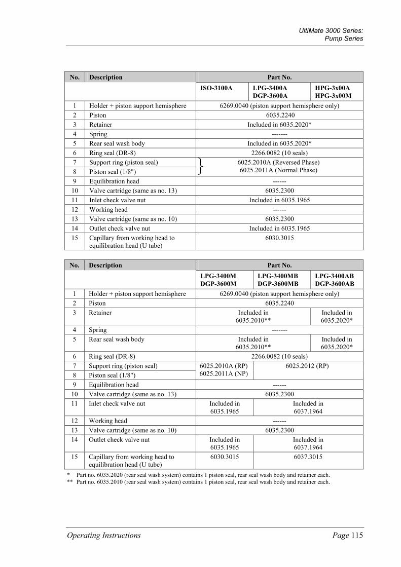
UltiMate 3000 Series: Pump Series
Operating Instructions Page 115
No. Description Part No. ISO-3100A LPG-3400A
DGP-3600A HPG-3x00A HPG-3x00M
1 Holder + piston support hemisphere 6269.0040 (piston support hemisphere only) 2 Piston 6035.2240 3 Retainer Included in 6035.2020* 4 Spring ------- 5 Rear seal wash body Included in 6035.2020* 6 Ring seal (DR-8) 2266.0082 (10 seals) 7 Support ring (piston seal) 6025.2010A (Reversed Phase)
6025.2011A (Normal Phase) 8 Piston seal (1/8") 9 Equilibration head ------
10 Valve cartridge (same as no. 13) 6035.2300 11 Inlet check valve nut Included in 6035.1965 12 Working head ------ 13 Valve cartridge (same as no. 10) 6035.2300 14 Outlet check valve nut Included in 6035.1965 15 Capillary from working head to
equilibration head (U tube) 6030.3015
No. Description Part No. LPG-3400M
DGP-3600M LPG-3400MB DGP-3600MB
LPG-3400AB DGP-3600AB
1 Holder + piston support hemisphere 6269.0040 (piston support hemisphere only) 2 Piston 6035.2240 3 Retainer Included in
6035.2010** Included in 6035.2020*
4 Spring ------- 5 Rear seal wash body Included in
6035.2010** Included in 6035.2020*
6 Ring seal (DR-8) 2266.0082 (10 seals) 7 Support ring (piston seal) 6025.2010A (RP)
6025.2011A (NP) 6025.2012 (RP)
8 Piston seal (1/8") 9 Equilibration head ------
10 Valve cartridge (same as no. 13) 6035.2300 11 Inlet check valve nut Included in
6035.1965 Included in 6037.1964
12 Working head ------ 13 Valve cartridge (same as no. 10) 6035.2300 14 Outlet check valve nut Included in
6035.1965 Included in 6037.1964
15 Capillary from working head to equilibration head (U tube)
6030.3015 6037.3015
* Part no. 6035.2020 (rear seal wash system) contains 1 piston seal, rear seal wash body and retainer each. ** Part no. 6035.2010 (rear seal wash system) contains 1 piston seal, rear seal wash body and retainer each.

UltiMate 3000 Series: Pump Series
Page 116 Operating Instructions
Semipreparative pump version
Fig. 42: Pump heads, pistons, and piston seals (here: HPG-3200P)
Semipreparative pump version No. Description Part No. 1 Piston 2267.0802A 2 Piston retainer 6004.8104 3 Piston bushing (5 bushings) 2090.8083 4 Retainer Included in 6025.2210A* 5 Rear seal wash body Included in 6025.2210A* 6 Ring seal (10 seals) 2266.0082 7 Support ring (piston seal) 6030.9010 (für Reversed Phase)
6030.9011 (für Normal Phase) 8 Piston seal 9 Capillary from working head to equilibration head (U tube) 5030.3025
10 Outlet check valve nut Included in 6035.1966 11 Valve cartridge (same as no. 14) 6035.2300 12 Working head with pressure transducer ------ 13 Inlet check valve nut Included in 6035.1966 14 Valve cartridge (same as no. 11) 6035.2300 15 Equilibration head (without pressure transducer) ------ 16
Connect the capillary from left equilibration head to Tee insert right equilibration head to Tee insert
Included in 6035.1969
* Part no. 6025.2210A (rear seal wash system) contains 1 piston seal, rear seal wash body and retainer each.

UltiMate 3000 Series: Pump Series
Operating Instructions Page 117
7.5.1 Visually Inspecting the Pump for Piston Seal Leakage
Each piston has two piston seals. The seals prevent solvent from leaking either into the rear seal wash system or over the piston and into the instrument. With the standard setup of the seal wash system (that is, the liquid reservoir is installed inside the pump), the detector on the liquid reservoir automatically checks the main piston seals for leakage (→ page 82). If rear seal washing is performed from an external liquid reservoir (→ page 83), the detector is not active.
In both cases, you can inspect the pump also visually for liquid leaks from the main piston seals.
Standard Setup with Internal Wash Liquid Reservoir
1. Turn rear seal washing off and on again. Open the Commands dialog box for the pump in Chromeleon and set RearSealWashSystem first to Off and then to Automatic. —Or— On the front panel display, select the Preferences menu and set Rear seal wash first to Off and then to Automatic.
The peristaltic pump starts pumping, delivers approximately 2 mL of liquid, and then stops.
2. Remove the silicone tubing from the pump head on the liquid reservoir (detector).
Fig. 43: Tubing connections on the internal liquid reservoir
3. Remove some of the liquid by shaking the tube.
4. Reconnect the tubing to the liquid reservoir.
5. Set the flow rate. Arrange the system in such a way that approximately 300 bar of backpressure is generated.

UltiMate 3000 Series: Pump Series
Page 118 Operating Instructions
6. To evaluate possible leakage, observe the air/liquid level in the silicone tube.
Tip: The peristaltic pump will start a new washing cycle after one hour. Therefore, be sure to finish your observation before that time.
7. If the level remains unchanged, the piston seals seal tightly. A rising or falling level indicates leakage from one or more of the main piston seals. In this case, replace all piston seals and the support rings (→ page 123).
Alternative Setup with External Wash Liquid Reservoir Bad retention time precision may indicate piston seal leakage. Observe the open end of the waste line. If liquid exits the waste line during the intervals indicates liquid leaks from the main piston seals. In this case, replace all piston seals and the support rings (→ page 123).

UltiMate 3000 Series: Pump Series
Operating Instructions Page 119
7.5.2 Replacing the Piston Seals
A defective piston seal allows leakage past the piston. This may cause unstable flow rates and baseline noise; in addition, it may make it difficult to prime the pump.
The seal replacement procedure consists of:
1. Removing the pump head and piston (→ page 120)
2. Removing the piston seals and support ring (→ page 123)
3. Cleaning the pistons (→ page 124)
4. Installing the piston, piston seals, support ring, and pump head (→ page 125)
5. After you have replaced the piston seals, observe the recommendations on page 130.
Tips: As standard, all pumps are equipped with piston seals made of UHMW-PE (RP). Keep in mind that using chloroform, trichlorobenzene, methylene chloride, tetrahydrofuran, or toluene as solvents chemically damages the UHMW-PE seals. Chemical reactions may also occur when using tetrachloromethan, diethyl ether, ethyl ether, di-isopropyl ether, ketones, methylbenzene, methycyclohexane, and monochlorobenzene. If you use these solvents, contact the Thermo Fisher Scientific sales organization for Dionex HPLC Products.
As standard, the pumps are fitted with reversed phase piston seals. However, normal phase seals can be installed instead if required. Depending on the application, the abrasion may be slightly increased. Therefore, check the permeability of the filter frit at regular intervals (→ page 112).
For information about the installation procedure and the corresponding part numbers, see section 7.5.2.2 (→ page 123).

UltiMate 3000 Series: Pump Series
Page 120 Operating Instructions
7.5.2.1 Removing the Pump Head and Piston To reach the piston heads and pistons, it is not necessary to open the pump enclosure. Tilt the front cover upward. The pistons are freely accessible via the pump heads.
All pumps 1. If necessary, purge the pump to remove toxic solvents.
2. Set the pump flow rate to 0. Wait until the system pressure is down to zero.
3. Disconnect all fluid connections from the pump head.
Fig. 44: Installed pump heads
4. Loosen the Allen screws on the two pump head (→ Fig. 44) and carefully remove the pump head.
Fig. 45: Pump head removed
5. Remove the support ring. The support ring may still be in the removed pump head.
6. Continue with the steps that are appropriate for your pump.
♦ For all pumps except HPG-3200P (→ page 121).
♦ For HPG-3200P pumps (→ page 122).
Capillary from working head to equilibration head (U tube)
Pump block outlet
Pump block inlet
Equilibration head Working head
Allen screw (each pump block has 4 screws)
Ring seal
Rear-seal wash body
Support ring

UltiMate 3000 Series: Pump Series
Operating Instructions Page 121
All pumps except HPG-3200P
7. Carefully remove the rear seal wash body from the piston (→ Fig. 47), by pulling it toward you. To do so, use the extractor from the pump accessories kit (→ Fig. 46). Avoid tilting. This may cause damage to the piston.
Fig. 46: Extractor for rear seal wash body Fig. 47: Extractor on rear seal wash body
8. Hold the piston as far as possible at its rear end. Move the piston, for example, upward, so that it is no longer in the center position.
Fig. 48: Piston moved upward
9. Tilt the piston and remove it from the magnet holder (→ Fig. 41, no. 1, page 114). 10. Verify that the hemisphere (part no. 6269.0040), which supports the piston, remained
in the holder. In rare cases, the hemisphere sticks to the piston and is removed with it. In this case, rub the hemisphere with a dry tissue. Apply some grease to the center of the holder (thin film). Insert the hemisphere with tweezers. The flat side must point toward you (→ Fig. 49).
Fig. 49: Magnet holder
Piston moved upward
Rear end of the piston
Magnet
Magnet holder
Piston support hemisphere

UltiMate 3000 Series: Pump Series
Page 122 Operating Instructions
HPG-3200P only
7. Carefully remove the rear seal wash body from the piston (→ Fig. 45), by pulling it toward you.
8. Remove the piston bushing from the piston, using the extractor from the pump accessories kit.
Fig. 50: Piston with piston bushing Fig. 51: Removing the piston bushing
9. Loosen the piston retainer (→ Fig. 42, no. 2, page 116), using the slotted screwdriver from the pump accessories kit, and remove the piston from the enclosure.
Piston bushing
Piston
Extractor

UltiMate 3000 Series: Pump Series
Operating Instructions Page 123
7.5.2.2 Removing the Piston Seals and Support Ring Each piston has two seals: a main piston seal (on the pump head) and a seal in the rear seal system.
Tip: Use a disassembled piston to remove the piston seal from the pump head. Do not use a sharp tool, such as tweezers. This will scratch the inside of the pump head; these scratches will prevent a proper seal and allow leakage when you install the new seal.
1. On the working head (with valve cartridges), use a blind nut (FS-8, part no. 6000.0044, for all pumps except biocompatible pumps; FS-8 biocompatible, part no. 6000.0144, for biocompatible pumps) to close the outlet valve.
2. On the equilibration head, close the holes with blind nuts.
3. Place a few drops of water on the main piston seal (for example, with a syringe). The seal is easier to remove when it is moist.
4. Push the piston into the pump head. The pressure loosens the seal. If you cannot remove the piston seal in this way, use an M4 screw (this is possible only for analytical pumps); for example, the one used for holding the pump heads. Insert the screw into the seal and remove the seal. This procedure destroys the piston seal.
Important: When replacing the piston seal in the pump head, always replace the support ring as well. (For part number information, see the follwing table.) This is to prevent leakage.
Even if you do not want to replace the seal in the rear seal body, visually inspect the seal to verify that it is neither worn nor bent. To see the seal, you have to remove the retainer (see the next step below).
Important: Lorsque vous remplacez le joint de piston de la tête de pompe, remplacez systématiquement la rondelle anti-extrusion. (Pour des informations sur les références des pièces, référez-vous au tableau ci-dessous.) Ceci est destiné à éviter toute fuite.
Même si vous ne voulez pas remplacer le joint dans le corps d'arrière-joint, inspectez visuellement le joint pour vérifier qu'il ni n'est porté ni est plié. Pour voir le joint, vous devez enlever l'arrêtoir (voir la prochaine étape ci-dessous).

UltiMate 3000 Series: Pump Series
Page 124 Operating Instructions
Description Part No.
Piston seal/support ring kit (reversed phase) for - ISO-3100A, LPG-3400A and M, DGP-3600A and M, and HPG-3x00A and M - LPG-3400AB and MB, DGP-3600AB and MB - HPG-3200P
6025.2010A* 6025.2012* 6030.9010*
Piston seal/support ring kit (normal phase) for - ISO-3100A, LPG-3400A and M, DGP-3600A and M, and HPG-3x00A and M - HPG-3200P
6025.2011A* 6030.9011*
* The kits include one support ring and two piston seals.
5. To remove the piston seal that is installed in the rear seal body, remove the retainer on the back of the rear seal wash body first, using the extractor tool from the accessories kit (→ Fig. 46, page 121 and Fig. 52, page 125). Then, remove the seal. Use the piston to push the piston seal out of the rear seal body. The seal does not only seal the rear seal wash system but also guides the piston. Therefore, always replace the seal when it is worn or bent.
7.5.2.3 Cleaning the Pistons All pumps
1. Remove the pump head and the piston if necessary (→ page 120).
2. Carefully rinse the piston, and then rub it several times with a dry, lint-free tissue.
3. Inspect the piston for signs of damage. If the piston is scratched or scored, replace it.
HPG-3200P only 4. Apply some thin-bodied, resin-free oil (thin film) only to the metal part of the piston.
Tip: Use a lamp to find out whether the piston is dirty.
Sapphire piston Hold the rear side of the piston into the light. Dirt particles will be enlarged by the refraction of the light. Ceramic piston Hold the piston into the light. While turning the piston, observe the reflection of the lamp.

UltiMate 3000 Series: Pump Series
Operating Instructions Page 125
7.5.2.4 Installing the Piston, Piston Seals, Support Ring, and Pump Head
Tip: Thermo Fisher Scientific recommends that you always install new piston seals when you install a piston.
1. Assemble the rear seal wash system. If you did not disassemble the rear seal wash system, continue with the step 5 that is appropriate for your pump.
2. Insert the piston into the rear seal wash body (from the side opposite the retainer; → Fig. 52).
3. Slide the new piston seal (mind the correct orientation) over the piston. (The piston is used only to facilitate centering during this process.) Insert the retainer into the rear seal body. Tighten the retainer finger-tight, and then use extractor to tighten the retainer gently until the seal snaps into place. Remove the piston so that the seal remains in the rear seal body.
Fig. 52: Assembling the rear seal wash system
Important: When installing the piston seals, make sure that the spring side of the seals faces away from the pump enclosure (→ Fig. 41 and Fig. 42, no. 8).
Important: Lorsque vous installez des joints de piston, assurez-vous que les côtés "ouverts" des joints, montrant le ressort spiral, soient dirigés vers l’avant de la tête de pompe (coté pression) (→ Fig. 41 et Fig. 42, no. 8).
4. Continue with the steps that are appropriate for your pump.
♦ For all pumps except HPG-3200P (→ 126).
♦ For HPG-3200P pumps (→ 128).
Rear-seal wash body
Seal
Piston inserted from opposite the retainer

UltiMate 3000 Series: Pump Series
Page 126 Operating Instructions
All pumps except HPG-3200P 5. Verify that the O-ring seal (part no. 6266.2202 for 5 seals) is installed on the rear seal
wash body (→ Fig. 53). Slightly grease the O-ring seal and metal part of the rear seal wash body if necessary.
Fig. 53: Rear seal wash body with O-ring seal
6. Insert the piston into the rear seal wash body only that far that you can slide the support ring and piston seal onto the other piston end. Then, slide the support ring and ring seal onto the piston.
7. Verify that the uninstalled pump head has no seal installed (for example, the old seal) and that the white ring seal is on the rear seal wash body (→ Fig. 45, page 120).
Slightly push the rear seal wash body into the pump head until the piston seal is correctly in place. Avoid tilting and only push the rear seal wash body. To avoid damage to the piston, do not push from the piston end.
Tip: To avoid damage to the piston seal during installation, Thermo Fisher Scientific recommends moistening the piston seal, piston, and pump head with HPLC-grade water directly before you install them.
8. Slide the spacing tool over the piston. Move the tool forward until it is stopped by the rear seal wash body. Remove the tool. The piston is now in the correct position for being installed in the pump head.
Fig. 54: Spacing tool
O-ring seal
Use this side of the tool with all pumps except LPG-3400M(B) and DGP-3600m(B).
Use this side of the tool (deeper spacing) with the LPG-3400M(B) and DGP-3600M(B).

UltiMate 3000 Series: Pump Series
Operating Instructions Page 127
9. Verify that the magnet holder is free from contaminants and that the piston support hemisphere is in the holder. It is important that the piston does not contact the magnet holder immediately upon installation. Therefore, perform the Change right pump pistons or Change left pump pistons command on the Control menu (→ page 71) or perform the related command in Chromeleon to move the pump in the appropriate position. Then, slide the pump head together with the rear seal wash body and piston into the pump block and tighten the Allen screws in turn.
Important: If you do not insert the piston seal in the way described above, but into the disassembled pump head, it may get jammed and thus become useless.
The working head is installed on the left side of the pump block (inlet). You can identify the head by the two large holes for the inlet and outlet valves.
Important: Si vous n'insérez pas le joint de piston de la manière décrite ci-dessus, mais dans la tête de pompe démontée, il peut se coincer de travers et ainsi devenir inutilisable.
La tête de travail est installée sur le côté gauche du bloc de pompe (entrée). Vous pouvez reconnaître la tête aux deux grands taraudages destinés aux supports des clapets d'entrée et de sortie.
10. Have the pump deliver about 1 mL/min (analytical pumps) or 300 µL/min (micro pumps). The magnet holder moves forward until the piston and magnet holder come into contact (indicated by an audible click). If you replace pistons, two clicks must be heard. Only then, both pistons are in the correct positions.
11. Reinstall the capillary connections as described in the All Pumps section (→ page 129).

UltiMate 3000 Series: Pump Series
Page 128 Operating Instructions
HPG-3200P only 5. Install the piston in the pump block and tighten the piston retainer using the slotted
screwdriver from the accessories kit.
6. Slide the piston bushing onto the piston. Be sure to install the bushing in the correct orientation (→ Fig. 55).
Fig. 55: Correct orientation of the piston bushing
7. Slide the complete rear seal wash body over the piston.
8. Slide the new support ring and the new piston seal onto the piston. Be sure to install the piston seal in the correct orientation. When the seal is installed correctly, the open side points toward the front.
Fig. 56: Rear seal wash system with seals and support ring
9. Slide the ring seal (part no. 2266.0082; 10 seals) onto the rear seal wash body (→ Fig. 42, no. 6).
10. Verify that the uninstalled pump head has no seal installed (for example, the old seal).
11. Slide the pump head onto the piston (turn and push gently as necessary) until the second piston seal is correctly in place.
Important: If you do not insert the piston seal in the way described above, but into the disassembled pump head, it may get jammed and thus become useless.
The working head is installed on the left side of the pump block (inlet). You can identify the head by the two large boreholes for the inlet and outlet valves.
Slide the bushing onto the piston in this direction.
Piston seal
Ring seal
Support ring

UltiMate 3000 Series: Pump Series
Operating Instructions Page 129
Important: Si vous n'insérez pas le joint de piston de la manière décrite ci-dessus, mais dans la tête de pompe démontée, il peut se coincer de travers et ainsi devenir inutilisable.
La tête de travail est installée sur le côté gauche du bloc de pompe (entrée). Vous pouvez reconnaître la tête aux deux grands taraudages destinés aux supports des clapets d'entrée et de sortie.
Tip: To avoid damage to the piston seal during installation, Thermo Fisher Scientific recommends moistening the piston seal, piston, and pump head with HPLC-grade water directly before you install them.
12. Tighten the pump head with the Allen screws.
13. Reinstall the capillary connections as described in the All Pumps section (→ page 129).
All pumps 14. Reinstall all capillary connections to the pump heads. When you install the solvent line
on the inlet valve, take care to avoid cross-threading.
HPG-3x00M only Due to limited space, it may be difficult to install the capillary from the left equilibration head to the outlet unit. Be careful not to bend the capillary on the equilibration head; this will prevent a proper seal and allow leakage. To facilitate the installation, follow the steps below:
a) Move the fitting screws on the capillary as far back as possible.
b) First, insert the capillary into the hole on the equilibration head. Then, slightly turn the capillary as necessary and insert the other end into the hole on the outlet unit. If you need to bend the capillary during the installation, be careful to bend the tubing only slightly and only at the position marked in Fig. 57. Only at these positions, the capillary is flexible enough to return to its original shape after being bent.
Fig. 57: Capillary from left equilibration head to outlet unit (HPG-3x00M)
c) Move the fitting screws back and tighten the capillary.
Connect to the outlet unit.
Connect to the left equilibration head.
Here the capillary is slightly flexible.

UltiMate 3000 Series: Pump Series
Page 130 Operating Instructions
15. Attach the tubing of the rear seal wash system to the corresponding capillaries (→ Fig. 7, page 22).
16. Rinse the pump thoroughly to prevent contaminants from entering the HPLC system. ♦ Rinse the pump with at least 30 mL of HPLC-grade water or pure organic solution.
♦ Loosen the purge valve screw to prevent rinsing liquid from entering the HPLC system.
17. After replacing the piston seals, observe the recommendations on page 130.
18. Test the pump for leakage (→ page 133). Tighten any leaking connections.
Tip: After you have exchanged the piston seals or pistons, update the related service information in Chromeleon. To do so, perform the PistonsChanged and SealsChanged commands.
7.5.2.5 Recommended Actions after Exchanging the Piston Seals Observe the following recommendation when you have exchanged the piston seals.
• Always exchange the liquid in the reservoir of the rear seal wash system and rinse the fluidics.
• Allow new piston seals to run in.
a) Connect drain tubing to the purge outlet.
b) Open the purge valve.
c) Operate the pump for 15 minutes with isopropanol at a flow rate of 1 mL/min. Do not have the pump deliver in circles.
d) Close the purge valve.
e) On the pump outlet, install a flow resistance, for example, a capillary, that can generate approximately 300 bar at a flow rate of 1 mL/min.
f) Have the pump deliver isopropanol at 1 mL/min for another 30 minutes.
g) Inspect the filter frit in the outlet unit for permeability (→ page 112). h) Uninstall the capillary and connect the pump to the system.
In rare cases, it may happen that new seals still show an increased leakage rate after several hours of operation. In this case, exchange the liquid in the reservoir of the rear seal wash system once again and rinse the fluidics.
• If leakage is observed with new piston seals, operate the pump for at least 2 hours at 350 bar to run in the seals. Note: In this case, tightening the pump head screws does not help.
• Never run the pump dry. Damage to the pistons or piston seals could result.

UltiMate 3000 Series: Pump Series
Operating Instructions Page 131
7.6 Replacing the Fuses
Warning: Before replacing the fuses, turn off the pump. Be sure to disconnect the power cord from its source.
Avertissement: Avant de remplacer les fusibles, arrêtez la pompe. Assurez-vous de bien débrancher le cordon d'alimentation de la source secteur.
1. Remove the fuse cartridge, using a small screwdriver (→ Fig. 58).
Fig. 58: Fuse cartridge
2. Replace the fuses with fuses of the appropriate rating. Thermo Fisher Scientific recommends always replacing both fuses.
Important: Do not operate the pump with only one fuse. Use only the fuses indicated in the following table.
Important: Ne faites pas fonctionner la pompe avec seulement un fusible. Utilisez uniquement les fusibles indiqués ci-dessous.
Description Part No.
Fuse, 2 A, slow-blow, 5 x 20 mm, 250V
Included in Fuses Kit, part no. 6030.9003 For information about which fuses are contained in the kit, see section 11.3 (→ page 169).
3. Reinstall the fuse cartridge.
4. Reconnect the power cord to its source and turn on the pump.
Fuse cartridge

UltiMate 3000 Series: Pump Series
Page 132 Operating Instructions
7.7 Vacuum Degasser
To avoid contamination of the degasser
• Prepare fresh solvents at regular intervals. • Rinse the degassing channels at regular intervals.
This is especially important for the channel that degases the aqueous solvent (for reverse-phase chromatography). Usually, it is sufficient to rinse all channels with organic solvent. Use a fresh bottle. When you use water and acetonitrile or methanol, it is usually sufficient to rinse the degassing channels once per week. However, adapt the rinsing intervals to the solvents in use. In persistent cases, for example reproducible ghost peaks in the chromatogram, follow the steps below: 1. Install a backpressure capillary on the pump outlet. The capillary should be
appropriate for generating a backpressure of 200 to 300 bar. 2. Rinse the degassing channels for 1 hour with 20% nitrid acid at the flow rate
normally used for your application. Use fresh HPLC-grade water. 3. Rinse the degassing channels with fresh HPLC-grade water until the pH value is
neutral. 4. Rinse the degassing channels for 2 hours, using fresh HPLC-grade acetonitrile
quality at the flow rate normally used for your application. 5. Prepare fresh solvents for your application using new bottles, and connect them to
the degassing channels. 6. Install new filter frits on the solvent lines. 7. Uninstall the backpressure capillary and reconnect the system as required by your
application. 8. Equilibrate the system.
In addition, observe the following
• Clean the solvent lines at regular intervals.
• Thermo Fisher Scientific advises against recycling the solvents. This may impair the degassing performance.
• When connecting the solvent lines, make sure that the connectors are free of contaminants. Even minute particles can allow air to enter the degasser, and thus reduce the unit's effectiveness.
• When replacing solvents, make sure that the solvents are miscible. Mix immiscible solvents with an intermediate solvent to replace them step-by-step.
• Thoroughly rinse the degasser with alcohol after operation. The alcohol does not need to be removed afterwards.
• For longer periods of inactivity and when using saliferous buffers (which may result in salt crystallization in the gas separation membrane, thereby impairing the degassing performance), rinse with de-ionized water followed by either methanol or ispropanol.

UltiMate 3000 Series: Pump Series
Operating Instructions Page 133
7.8 Testing the Pump for Leakage
After you have carried out any maintenance or repair work on the fluid system, test the pump for leakage.
Tips: Perform the test for the two pumps of a DGP-3600 separately if necessary.
In Chromeleon, you can run General Leak Test (→ page 87) to test the pump for leakage.
1. Close the pump outlet with an appropriate blind nut.
Description Part No.
Blind nut (FS-8) for all pumps except biocompatible pumps 6000.0044
Blind nut (FS-8) for biocompatible pumps 6000.0144
2. In Chromeleon, set the upper pressure limit: For pumps without flow splitter assignment: Set Pressure > UpperLimit. For pumps with flow splitter assignment: Set MasterPressure > UpperLimit.
Pump Type Upper Pressure Limit
Analytical and micro pumps 400 bar
Semipreparative pumps 100 bar
3. In Chromeleon, select a flow rate of, for example, 50 µL/min.
4. Decrease the flow as soon as the pressure builds up (see table).
Pump Type Pressure typically
Analytical and micro pumps between 100 and 200 bar
Semipreparative pumps between 80 and 100 bar
5. Have the pump deliver some µL/min until the appropriate pressure has build up.
Pump Type Pressure Build Up
Analytical and micro pumps between 100 and 200 bar
Semipreparative pumps between 80 and 100 bar
6. When this pressure has been built up and when the pump delivers a master flow of 1 µL/min, the pressure should increase or remain constant at least. If it does not, this indicates possible leakage.

UltiMate 3000 Series: Pump Series
Page 134 Operating Instructions
7. In this case, find and eliminate the cause for the leak. Possible sources are:
♦ Capillary connections Inspect them for signs of leakage and perform the test described below this list.
♦ Inline filter in the outlet unit, especially important with biocompatible pumps Perform the test described below this list.
♦ Piston seals
♦ Inspect the piston seals for leakage (→ page 117) and tighten leaking connections, if necessary.
♦ If leakage continues, replace the piston seals (→ page 119).
♦ If leakage is observed with new piston seals, operate the pump for at least 2 hours at 350 bar to run in the seals. Note: In this case, tightening the pump head screws does not help.
♦ Outlet unit seal Inspect the seal for signs of leakage and perform the test described below this list.
♦ Check valves Tighten the check valve screws and perform the test described below this list.
♦ Purge screw Inspect the purge screw and outlet unit. To make sure that the purge screw is not too tight, perform the test described below this list.
Test a) Pressure up the pump. This is the best way to identify a leaking connection.
b) Allow 5 minutes for the pump to stabilize. This is important as the pressure drops faster during the first 5 minutes, because the seals and other components have to adjust the pressure.
c) After the stabilization time, monitor the pressure drop.
d) Tighten the connection a little more tight. The pressure will suddenly increase a little.
e) Monitor if the pressure drops at the same rate as before. If the pressure drops significantly slower, the connection was leaking.
8. Reset the upper pressure limit to the value used before the leakage test.

UltiMate 3000 Series: Pump Series
Operating Instructions Page 135
8 Optimizing the Pump for Special Application The following pumps have a dynamic mixing chamber (volume: 328 µL) in the outlet unit: LPG-3400A, LPG-3400AB, DGP-3600A, DGP-3600AB, and HPG-3x00A
Fig. 59: Outlet unit with mixing chamber
No. Description
1 Outlet unit installation screws 2 Pressure transducer for the system pressure 3 Purge valve 4 Inline filter, consisting of a filter holder and filter frit 5 Gasket 6 Stirrer 7 Mixing chamber (base)
You may want to optimize the pump for special applications. To do so, the following kits are available:
• Mixing Chamber Extension kits - to extend the mixing chamber volume by 600 µL to a total volume of 928 µL - to extend the mixing chamber volume by 1200 µL to a total volume of 1528 µL for the following pumps: LPG-3400A, LPG-3400AB, DGP-3600A, DGP-3600AB, HPG-3200A, and HPG-3400A (→ page 136)
Tip: As a standard, HPG-3200P pumps are shipped with an extended mixing chamber (total chamber volume = 928 µL).
• Micro Flow kit for pumps LPG-3400A, LPG-3400AB, DGP-3600A, and DGP-3600AB (→ page 138)

UltiMate 3000 Series: Pump Series
Page 136 Operating Instructions
8.1 Mixing Chamber Extension
To increase the mixing chamber volume, install the appropriate extension.
Description Part No.
Mixing chamber extension (to extend the mixing chamber volume by 600 µL) for LPG-3400A, DGP-3600A, HPG-3200A, and HPG-3400A LPG-3400AB and DGP-3600AB The extension kit includes: 1 extension ring (600 µL) 3 screws to attach the extension ring 2 mixing chamber gaskets
6035.1978 6037.1978
Mixing chamber extension (to extend the mixing chamber volume by 1200 µL) for LPG-3400A,DGP-3600A, HPG-3200A, HPG-3400A, and HPG-3200P LPG-3400AB and DGP-3600AB The extension kits includes: 1 extension ring (1200 µL) 3 screws to attach the extension ring 2 mixing chamber gaskets
6035.1979 6037.1979
Tip: Two kits are required for a DGP-3600A or DGP-3600AB.
Fig. 60: Outlet unit with mixing chamber and optional extension
No. Description No. Description
1 Outlet unit installation screws 6 Mixing chamber extension 2 Pressure transducer (system pressure) 7 Gasket 3 Purge valve 8 Stirrer 4 Inline filter, consisting of a
filter holder and filter frit 9 Mixing chamber (base)
5 Gasket 10 Outlet unit

UltiMate 3000 Series: Pump Series
Operating Instructions Page 137
To install the mixing chamber extension
1. If necessary, purge the pump to remove toxic solvents.
2. Turn off the pump and disconnect the power cord from its source.
3. Tilt the front panel upward.
4. Disconnect the capillary on the pump outlet.
5. Remove the installation screws from the outlet unit (→ Fig. 60, no. 1), and then carefully remove the outlet unit (→ Fig. 60, no. 10).
Tip: Keep the installation screws in case you wish to remove the extension later.
6. Remove the old gasket (→ Fig. 60, no. 7).
7. Place the mixing chamber extension (→ Fig. 60, no. 6) on a flat surface (for example, drip tray). Install the gasket (→ Fig. 60, no. 5) and the outlet unit onto the mixing chamber extension. Insert the long installation screws (shipped with the mixing chamber extension kit) into the openings on the outlet unit.
8. Check that the stirrer (→ Fig. 60, no. 8) is in the mixing chamber. Insert the second gasket (→ Fig. 60, no. 7) into the mixing chamber base (→ Fig. 60, no. 9). If the gasket does not adhere to the base, apply some liquid to wet the seal before insertion.
9. Hold the outlet unit by the extension ring and insert the assembly into the mixing chamber base. Make sure that the seals (→ Fig. 60, nos. 5 and 7) remain in their correct positions.
10. Install the outlet unit by tightening all installation screws in turn. Tighten the screws just until you suddenly have to use force to turn in the screws. Do not tighten any further to avoid damage to the screws and screwdriver.
11. Reconnect the power cord to its source and turn on the pump.
12. Purge all channels (→ page 54).
13. Test the pump for leakage (→ page 133).
Tip: After you have installed the mixing chamber extension, verify in Chromeleon that the MixingChamber property is set to the correct value. If it is not, the diagnostics tests may not provide reliable results.
To uninstall the mixing chamber extension If you want to remove the extension, follow the steps above. Remove the mixing chamber extension including the ring seal. Reinstall the outlet unit onto the mixing chamber base, using the short installation screws and a new gasket.

UltiMate 3000 Series: Pump Series
Page 138 Operating Instructions
8.2 Micro Flow Kit
To reduce the delay volume for a low-pressure pump, install the Micro Flow option.
Description Part No.
Micro Flow kit for LPG-3400A and DGP-3600A pumps Micro Flow kit for LPG-3400AB and DGP-3600AB pumps The kit contains the following components: 1 L connection 1 Micro flow ring seal 1 capillary from proportioning valve to working head Tips: • Two kits are required for a DGP-3600A. • LPG-3400M, LPG-3400MB, DGP-3600M, and DGP-3600MB are shipped with the
Micro Flow option as standard.
6035.1977 6037.1977
Fig. 61: Outlet unit with micro flow option
No. Description
1 Outlet unit installation screws 2 Pressure transducer for system pressure 3 Purge valve 4 Inline filter, consisting of a filter holder and filter frit 5 Micro flow ring seal 6 L connection 7 Outlet unit

UltiMate 3000 Series: Pump Series
Operating Instructions Page 139
To install the micro flow option
1. If necessary, purge the pump to remove toxic solvents.
2. Turn off the pump and disconnect the power cord from its source.
3. Tilt the front panel upward.
4. Disconnect the capillary from the pump outlet and on the mixing chamber bottom part (→ Fig. 59, page 135, no. 7).
5. Remove the installation screws from the outlet unit (→ Fig. 61, no. 1), and then carefully remove the outlet unit (→ Fig. 61, no. 7).
6. Remove the mixing chamber base, old gasket, and stirrer (→ Fig. 59, page 135, nos. 5 through 7).
7. Install the L connection (→ Fig. 61, no. 6) to the position of the mixing chamber base so that the capillary connections are in a horizontal position (→ Fig. 62, page 140).
8. Insert the micro flow ring seal (→ Fig. 61, no. 5) into the L connection. If the seal does not adhere to the connection, apply a bit of liquid to wet the seal before insertion.
9. Insert the outlet unit into the L connection. Make sure that the seal remains in the correct position.
10. Install the outlet unit by tightening all installation screws in turn. Tighten the screws just until you suddenly have to use force to turn in the screws. Do not tighten any further to avoid damage to the screws and screwdriver.
11. Reinstall the capillary connections.
12. Replace the tubing (ECTFE) from the proportioning valve to the working head (→ Fig. 66, page 147 and Fig. 68, page 149) with the PEEK tubing from the Micro Flow option.
Tip: Keep the tubing in case you wish to remove the Micro Flow kit later.
13. Reconnect the power cord to its source and turn on the pump.
14. Purge all channels (→ page 54).
15. Test the pump for leakage (→ page 133).
Tip: After you have installed the micro flow option, verify in Chromeleon that the MixingChamber property is set to the correct value. If it is not, the diagnostics tests may not provide reliable results.

UltiMate 3000 Series: Pump Series
Page 140 Operating Instructions
To uninstall the micro flow option
1. If necessary, purge the pump to remove toxic solvents.
2. Turn off the pump and disconnect the power cord from its source.
3. Tilt the front panel upward.
4. Disconnect the capillary from the pump outlet and on the L connection.
5. Remove the installation screws from the outlet unit (→ Fig. 61, no. 1), and then carefully remove the outlet unit (→ Fig. 61, no. 7).
6. Remove the L connection (→ Fig. 61, no. 6) and the old micro flow ring seal.
7. Install the mixing chamber base to the position of the L connection so that the capillary connection is in a horizontal position.
Fig. 62: Capillaries connected to the mixing chamber base
8. Clean the mixing chamber bottom part and insert the stirrer (→ Fig. 59, page 135).
9. Insert the gasket into the mixing chamber base. If the gasket does not adhere to the base, apply some liquid to wet the seal before insertion.
10. Place the outlet unit onto the mixing chamber base. Make sure that the gasket remains in the correct position.
11. Install the outlet unit by tightening all installation screws in turn. Tighten the screws just until you suddenly have to use force to turn in the screws. Do not tighten any further to avoid damage to the screws and screwdriver.
12. Replace the (PEEK) tubing from the proportioning valve to the working head (→ Fig. 66, page 147 and Fig. 68, page 149) with the (ECTFE) tubing that was removed during installation of the Micro Flow option.
13. Reconnect the capillary to the pump outlet and mixing chamber base.
14. Reconnect the power cord to its source and turn on the pump.
15. Purge all channels (→ page 54).
16. Test the pump for leakage (→ page 133).

UltiMate 3000 Series: Pump Series
Operating Instructions Page 141
8.3 Static Mixer
To improve the mixing quality of the two combined solvent streams delivered by a pump HPG-3x00M, install the static mixer.
Description Part No.
Static mixer kit, 50 µL, including: - Mixer capillary (0.18 mm I.D.; 180 mm long) + appropriate fittings - Static mixer cartridge (50 µL) - Static mixer housing (2 pieces) - Installation instructions
6035.0002
Install the static mixer as described in the installation instructions shipped with the mixer kit.
Tips: Store the mixer cartridge in a safe place to avoid that the end seals are scratched or damaged.
The mixer cartridge is available also as a separate spare part (part no. 6268.5050).

UltiMate 3000 Series: Pump Series
Page 142 Operating Instructions

UltiMate 3000 Series: Pump Series
Operating Instructions Page 143
9 Inside Front Panel Views and Fluid Connections The sections listed in the table provide a short overview of the inside front panel views and the fluid connections of the UltiMate 3000 system series pumps. In addition, section 9.3.3 describes the special aspects to be considered with a high-pressure gradient system.
For the … Find information about the …. On page ….
Isocratic pump
ISO-3100A Inside front panel view Fluid connections
144 145
Low-pressure gradient pumps
LPG-3400 Inside front panel view Fluid connections
146 147
DGP-3600 Inside front panel view Fluid connections
148 149
High-pressure gradient pumps
HPG-3200 Inside front panel view Fluid connections
150 151
HPG-3400 Inside front panel view Fluid connections
153 154
Special aspects Gradient combinations Double Flow mode HPG-3200P semipreparative pump
156 156 157

UltiMate 3000 Series: Pump Series
Page 144 Operating Instructions
9.1 Isocratic Pump (IS0-3100A)
9.1.1 Inside Front Panel
Fig. 63: Inside front panel
No. Description Part No.
1 Outlet unit with pressure transducer and purge valve (→ page 23)
------
2 Peristaltic pump ------
3 Leak sensor (→ page 25) ------
4 Equilibration head ------
5 Working head ------
6 Liquid reservoir of the rear seal wash system 6030.9501 (2 reservoirs)
1 2
3
4 5 6

UltiMate 3000 Series: Pump Series
Operating Instructions Page 145
9.1.2 Fluid Connections
Fig. 64: Fluid connections
No. Description Part No.
1 Working head ------ 2 Capillary from working head to equilibration head 6030.3015* 3 Equilibration head ------ 4 Capillary from equilibration head to outlet unit 6035.3011* 5 Outlet unit with pressure transducer and purge valve
(→ page 23) ------
* These part numbers also include the appropriate fittings and ferrules.

UltiMate 3000 Series: Pump Series
Page 146 Operating Instructions
9.2 Low-Pressure Gradient Pumps
9.2.1 LPG-3400
9.2.1.1 Inside Front Panel
Fig. 65: Inside front panel
No. Description Part No.
1 Outlet unit with pressure transducer, purge valve, and inline filter (→ page 23) It depends on the pump variant whether the outlet unit includes a mixing chamber (→ page 24).
------
2 Peristaltic pump ------
3 Leak sensor (→ page 25) ------
4 Equilibration head ------
5 Working head ------
6 4-channel proportioning valve ------
7 Integrated 4-channel vacuum degasser ------
8 Liquid reservoir of the rear seal wash system 6030.9501 (2 reservoirs)
1 2
3
4 5 8 7 6

UltiMate 3000 Series: Pump Series
Operating Instructions Page 147
9.2.1.2 Fluid Connections The integrated online degasser is connected to the low-pressure side of the solvent delivery system, that is, the pump inlet.
Fig. 66: Fluid connections (The arrows indicate the direction of flow.)
No. Description Part No.
1 Integrated online degasser ------
2 Tubing from degasser to proportioning valve 6035.2540* (set of 4)
3 4-channel proportioning valve ------
4 Tubing from proportioning valve to working head LPG -3400A and LPG-3400AB LPG-3400M and LPG-3400MB
6035.2515* 6035.2514*
5 Working head ------
6 Capillary from working head to equilibration head LPG-3400A and LPG-3400M LPG-3400AB and LPG-3400MB
6030.3015* 6037.3015*
7 Equilibration head ------
8 Capillary from equilibration head to outlet unit LPG-3400A LPG-3400AB LPG-3400M LPG-3400MB
6035.3011* 6037.3020* 6035.3014* 6037.3011*
9 Outlet unit with pressure transducer, purge valve, and inline filter (→ page 23). It depends on the pump variant whether the outlet unit includes a mixing chamber (→ page 24).
------
* These part numbers also include the appropriate fittings and ferrules.

UltiMate 3000 Series: Pump Series
Page 148 Operating Instructions
9.2.2 DGP-3600
9.2.2.1 Inside Front Panel
Fig. 67: Inside front panel
No. Description Part No.
1 Outlet unit with pressure transducer, purge valve, and inline filter (→ page 23) It depends on the pump variant whether the outlet unit includes a mixing chamber (→ page 24).
------
2 Working head ------
3 Equilibration head ------
4 Peristaltic pump ------
5 Leak sensor (→ page 25) ------
6 3-channel proportioning valve ------
7 Liquid reservoir of the rear seal wash system 6030.9501 (2 reservoirs)
1 4
5
7 6 6
2 3 1 2 3

UltiMate 3000 Series: Pump Series
Operating Instructions Page 149
9.2.2.2 Fluid Connections
Fig. 68: Fluid connections (The arrows indicate the direction of flow.)
No. Description Part No.
SRD-3600 Solvent Rack with analytical 6-channel vacuum degasser 5035.9230 1 Solvent lines from degasser to proportioning valve 6030.2547*
(set of 3) 2 3-channel proportioning valve ------ 3 Tubing from proportioning valve to working head
DGP-3600A and DGP-3600AB DGP-3600M and DGP-3600MB
6035.2515* 6035.2514*
4 Working head ------
5 Capillary from working head to equilibration head DGP-3600A and DGP-3600M DGP-3600AB and DGP-3600MB
6030.3015* 6037.3015*
6 Equilibration head ------ 7 Capillary from equilibration head to outlet unit
DGP-3600A DGP-3600AB DGP-3600M DGP-3600MB
6035.3011* 6037.3020* 6035.3014* 6037.3011*
8 Outlet unit with pressure transducer, purge valve, and inline filter (→ page 23) It depends on the pump variant whether the outlet unit includes a mixing chamber (→ page 24).
------
* These part numbers also include the appropriate fittings and ferrules.
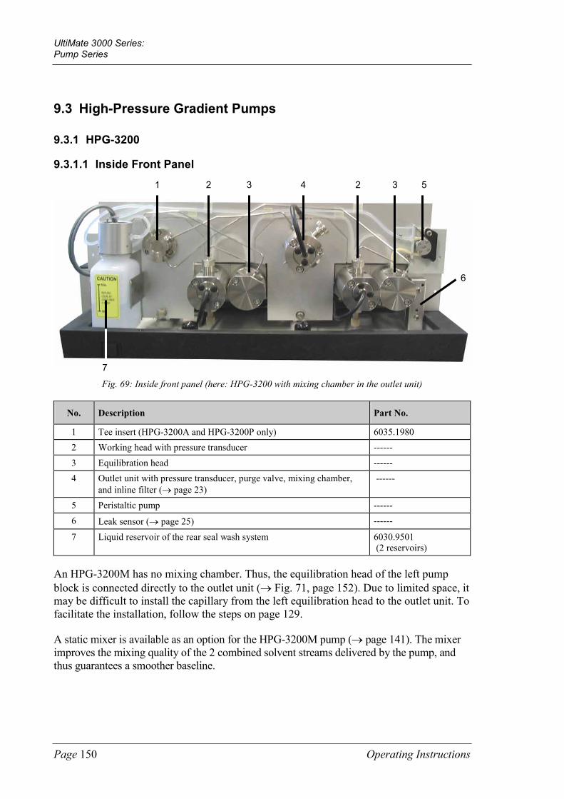
UltiMate 3000 Series: Pump Series
Page 150 Operating Instructions
9.3 High-Pressure Gradient Pumps
9.3.1 HPG-3200
9.3.1.1 Inside Front Panel
Fig. 69: Inside front panel (here: HPG-3200 with mixing chamber in the outlet unit)
No. Description Part No.
1 Tee insert (HPG-3200A and HPG-3200P only) 6035.1980 2 Working head with pressure transducer ------ 3 Equilibration head ------ 4 Outlet unit with pressure transducer, purge valve, mixing chamber,
and inline filter (→ page 23) ------
5 Peristaltic pump ------ 6 Leak sensor (→ page 25) ------
7 Liquid reservoir of the rear seal wash system 6030.9501 (2 reservoirs)
An HPG-3200M has no mixing chamber. Thus, the equilibration head of the left pump block is connected directly to the outlet unit (→ Fig. 71, page 152). Due to limited space, it may be difficult to install the capillary from the left equilibration head to the outlet unit. To facilitate the installation, follow the steps on page 129.
A static mixer is available as an option for the HPG-3200M pump (→ page 141). The mixer improves the mixing quality of the 2 combined solvent streams delivered by the pump, and thus guarantees a smoother baseline.
1 5
6
2 3 4 2 3
7

UltiMate 3000 Series: Pump Series
Operating Instructions Page 151
9.3.1.2 Fluid Connections
Fig. 70: Fluid connection (HPG-3200A with mixing chamber in the outlet unit)
The arrows indicate the direction of flow. With an HPG-3200P, the capillaries run slightly different.
No. Description Part No.
SRD-3200 Solvent Rack with analytical 2-channel vacuum degasser (for use with HPG-3200A only)
5035.9250
1 Solvent lines from analytical degasser to working head (for use with HPG-3200A only)
6035.2530* (set of 2)
2 Working head with pressure transducer ------ 3 Capillary from working head to equilibration head
HPG-3200A HPG-3200P
6030.3015* 5030.3025*
4 Equilibration head ------ 5 Capillary from left equilibration head to Tee insert
HPG-3200A HPG-3200P
Included in: 6035.1967* 6035.1969*
6 Capillary from right equilibration head to Tee insert HPG-3200A HPG-3200P
Included in: 6035.1967* 6035.1969*
7 Tee insert 6035.1980 8 Capillary from Tee insert to outlet unit
HPG-3200A HPG-3200P
Included in: 6035.1967* 6035.1969*
9 Outlet unit with pressure transducer, purge valve, mixing chamber, and inline filter (→ page 23)
------
* These part numbers also include the appropriate fittings and ferrules.

UltiMate 3000 Series: Pump Series
Page 152 Operating Instructions
Fig. 71: Fluid connections (HPG-3200M) The arrows indicate the direction of flow.
No. Description Part No.
SRD-3200 Solvent Rack with analytical 2-channel vacuum degasser 5035.9250 1 Solvent lines from degasser to working head 6035.2530*
(set of 2) 2 Working head with pressure transducer ------ 3 Capillary from working head to equilibration head 6030.3015*
4 Equilibration head ------ 5 Capillary from left equilibration head to outlet unit Included in:
6035.1968* 6 Capillary from right equilibration head to outlet unit Included in:
6035.1968* 7 Outlet unit with pressure transducer, purge valve, and inline filter
(→ page 23) ------
* These part numbers also include the appropriate fittings and ferrules.

UltiMate 3000 Series: Pump Series
Operating Instructions Page 153
9.3.2 HPG-3400
9.3.2.1 Inside Front Panel
Fig. 72: Inside front panel (here: HPG-3400A with mixing chamber in the outlet unit)
No. Description Part No.
1 Tee insert (HPG-3400A only) 6035.1980 2 Working head with pressure transducer ------ 3 Equilibration head ------ 4 Outlet unit with pressure transducer, purge valve, mixing chamber,
and inline filter (→ page 23) ------
5 Peristaltic pump ------ 6 Leak sensor (→ page 25) ------
7 Solvent Selector "2 from 4" ------ 8 Liquid reservoir of the rear seal wash system 6030.9501
(2 reservoirs)
An HPG-3400M has no mixing chamber. Thus, the equilibration head of the left pump block is connected directly to the outlet unit (→ Fig. 74, page 155). Due to limited space, it may be difficult to install this capillary from the left equilibration head to the outlet unit. To facilitate the installation, follow the steps on page 129.
A static mixer is available as an option for the HPG-3200M pump (→ page 141). The mixer improves the mixing quality of the 2 combined solvent streams delivered by the pump, and thus guarantees a smoother baseline.
1 5
6
2 3 4 2 3
8 7 7

UltiMate 3000 Series: Pump Series
Page 154 Operating Instructions
9.3.2.2 Fluid Connections
Fig. 73: Fluid connections (HPG-3400A with mixing chamber in the outlet unit)
The arrows indicate the direction of flow.
No. Description Part No.
SRD-3400 Solvent Rack with analytical 4-channel vacuum degasser 5035.9245 1 Solvent lines from degasser to solvent selector 6035. 2532*
(set of 4) 2 Solvent selector "2 from 4" ------ 3 Tubing from solvent selector to working head 6035.2515* 4 Working head with pressure transducer ------ 5 Capillary from working head to equilibration head 6030.3015*
6 Equilibration head ------ 7 Capillary from left equilibration head to Tee insert Included in:
6035.1967* 8 Capillary from right equilibration head to Tee insert Included in:
6035.1967* 9 Tee insert 6035.1980 10 Capillary from Tee insert to outlet unit Included in:
6035.1967* 11 Outlet unit with pressure transducer, purge valve, mixing chamber, and
inline filter (→ page 23) ------
* These part numbers also include the appropriate fittings and ferrules.

UltiMate 3000 Series: Pump Series
Operating Instructions Page 155
Fig. 74: Fluid connections (HPG-3400M)
The arrows indicate the direction of flow.
No. Description Part No.
SRD-3400 Solvent Rack with analytical 4-channel vacuum degasser 5035.9245 1 Solvent lines from degasser to solvent selector 6035.2532*
(set of 4) 2 Solvent selector "2 from 4" ------ 3 Tubing from solvent selector to working head 6035.2515* 4 Working head with pressure transducer ------ 5 Capillary from working head to equilibration head 6030.3015*
6 Equilibration head ------ 7 Capillary from left equilibration head to outlet unit Included in
6035.1968* 8 Capillary from right equilibration head to outlet unit Included in
6035.1968* 9 Outlet unit with pressure transducer, purge valve, and inline filter
(→ page 23) ------
* These part numbers also include the appropriate fittings and ferrules.

UltiMate 3000 Series: Pump Series
Page 156 Operating Instructions
9.3.3 Special Aspects of a High-Pressure Gradient System
The HPG-3x00 high-pressure gradient pumps operate with two pump blocks that are integrated in a single enclosure. Operation of the high-pressure gradient pump is identical to the low-pressure gradient pump (LPG). However, consider the information in the following sections.
9.3.3.1 Supported Gradient Combinations For an HPG-3400 pump with "2 from 4" solvent selector, channels A and C are connected to pump block 1 (left), while channels B and D are connected to pump block 2 (right). The solvent selector supports the following combinations of binary high-pressure gradients:
Pump block 1 (left) Pump block 2 (right)
Solvent A Solvent B
Solvent A Solvent D
Solvent C Solvent B
Solvent C Solvent D
In a specific time step, each pump block delivers only one of the two channels (100%). It is not possible to specify a mixing ratio for the two channels connected to the same pump block (A and C; B and D).
If you enter a portion for solvent C while solvent A is already set, the portion for solvent A is automatically reduced to 0%. The same applies to channels B and D on the second pump block. For example, if you enter a portion for solvent D (D = 20%), while the portions for solvents B and C are already set (B = 40%, C = 60%), solvent C is automatically increased to 80%. The same applies to all other channels.
9.3.3.2 Double Flow Mode HPG models support the double flow mode. This mode enables maximum flow rates of 20 mL/min (analytical and micro pumps) or 100 mL/min (semipreparative pump). The double flow mode is available for each solvent combination and composition supported by the HPG-pump. The pump automatically calculates the flow rate maximum considering that none of the two pump blocks delivers more than 10 mL/min (analytical version) or 50 mL/min (semipreparative pump).
Example A: Both pump blocks of an analytical pump deliver 50%. Each block then delivers 10 mL/min thus, reaching the flow rate maximum of 20 mL/min.

UltiMate 3000 Series: Pump Series
Operating Instructions Page 157
Example B: Pump block A of an analytical pump delivers 60% and block B delivers 40%. Block A then delivers 10 mL/min while block B delivers correspondingly less, that is, 6.667 mL/min. In this case, the total maximum flow rate is 16.667 mL/min.
9.3.4 HPG-3200P Semipreparative Pump
The HPG-3200P is the semipreparative pump in the UltiMate 3000 system series. Please observe the following when operating this pump:
• Only use the solvent lines shipped with the pump (part no. 6250.4301). These lines have an inner diameter of 3.0 mm.
• Only use the filter frits from the accessories kit (also included in part no. 6035.1964).
• Do not prolong the solvent lines.
• Especially for applications with high flow rates, make sure that the solvent reservoirs are located near the pump; they should be on the same level or higher. This is to avoid formation of air bubbles in the reservoirs.
• Thermo Fisher Scientific recommends using a preparative degasser. Do not connect an analytic degasser to the semipreparative pump. Else, degas the solvent, for example, in an ultrasonic bath.

UltiMate 3000 Series: Pump Series
Page 158 Operating Instructions

UltiMate 3000 Series: Pump Series
Operating Instructions Page 159
10 Technical Information Technical information: November 201. All technical specifications are subject to change without notice.
ISO-3100A LPG-3400A/ LPG-3400AB
DGP-3600A DGP-3600AB
HPG-3200A/ HPG-3400A
HPG-3200P
Flow rate range Recommended Settable
µL/min 50–10,000 1-10,000
µL/min 200–10,000
1-10,000
µL/min 200–10,000
1-10,000
µL/min 100–10,000
1-10,000
mL/min 0.5–50
0.001-50
Flow rate accuracy ±0.1% at 1 mL/min
±0,1%
Flow rate precision <0.05% RSD or <0.01 min SD, whichever is greater <0.1% RSD at 3 mL/min
Pressure range 2-50 MPa (7250 psi) 1-10 MPa (1450 psi) (short term:
15 MPa-2100 psi)
Pressure ripple Typical <0.2 MPa or <1%, whichever is greater Typical <0.2 MPa or <1%
whichever is greater
Proportioning accuracy
-- ±0.5% of fullscale
±0.5% of fullscale
±0.2% of fullscale
±0.2% of fullscale
Proportioning precision
-- <0.2% SD at 2 mL/min
<0.2% SD at 2 mL/min
<0.2% SD at 2 mL/min
<0.2% SD at 5 mL/min
No of eluent lines 1 4 6 (2 x 3) 2 2
Grad. delay volume -- 690 µL or LPG-3400A:
360 µL with Micro Flow kit
690 µL or DGP-3600A:
360 µL with Micro Flow kit
375 µL 1035 µL
Solvent degassing External (optional)
Built-in 4-channel degasser (channel volume: 670 µL)
External (optional)
External (optional)
--
Weight 16.2 kg (35.2 lb) 17.9 kg (39.4 lb) 21.5 kg (47.3 lb) 20.8 kg (45.8 lb) 20.8 kg (45.8 lb)
Dimensions (h x w x d): 19 x 42 x 51 cm (7.5 x 16.5 x 20 in.)
PC connection All functions controllable via USB 1.1; integrated USB hub with three free USB ports
I/O interfaces 3 digital inputs, 4 programmable relays, 1 analog output for pressure monitoring 15-pin D-Sub connector for Solvent Rack/degasser connection
Safety features Leak sensor Active rear seal washing with monitoring of the piston seal tightness and the liquid level of the liquid reservoir
User input/ display
LCD indicating system parameters Standby button; 3 LEDs (Power, Connected, and Status) for status monitoring 4 function keys for operation during initial installation and maintenance
GLP In Chromeleon: Full support of automatic equipment qualification (AutoQ™) and System Wellness monitoring. All system parameters are logged in the Chromeleon Audit Trail.
Wetted parts Stainless steel or titanium (for biocompatible pumps), sapphire, ruby, UHMW polyethylene, PCTFE, PTFE, PEEK™, zirconium oxide, aluminum oxide, FEP, ECTFE
Power requirements 150 VA (100-120V, 60 Hz; 200-240V, 50 Hz)
Emission sound pressure level:
< 70 dB(A) in 1-m-distance
Environmental conditions
Range of use: Indoor use; Temperature: 10 °C to 35 °C; Air humidity:80% relative humidity, non-condensing; Overvoltage category: II; Pollution degree: 2

UltiMate 3000 Series: Pump Series
Page 160 Operating Instructions
HPG-3200M/
HPG-3400M LPG-3400M LPG-3400MB
DGP-3600M/ DGP-3600MB
LPG-3400M(B) + FLM-3x00(B)
DGP-3600M(B) + FLM-3x00(B)
Flow rate range Recommended (Settable)
µL/min 20–10,000 (1-10,000)
µL/min 10–2,500 (1-2,500 )
µL/min 10–2,500 (1-2,500)
Nano: 50–1,000 nL/min Cap: 0.5-10 µL/min Micro: 10-160 µL/min
Nano: 50–1,000 nL/min Cap: 0.5-10 µL/min Micro: 10-160 µL/min
Flow rate accuracy ±0.1% at 1 mL/min
±0.5% at 200 µL/min
(typical ±0.25% at 200 µL/min)
±0.5% at 200 µL/min
(typical ±0.25% at 200 µL/min)
Nano: ±3% at 300 nl/min Cap: ±1.5% at 4 µL/min Mikro: ±1% at 50 µL/min
Nano: ±3% at 300 nl/min Cap: ±1.5% at 4 µL/min Mikro: ±1% at 50 µL/min
Flow rate precision <0.05% RSD or <0.01 min SD, whichever is greater <0.1% RSD <0.1% RSD
Pressure range 2-50 MPa (7250 psi) 1-50 MPa (7250 psi)
Pressure ripple Typical <0.2 MPa or <1% whichever is greater
-- --
Proportioning accuracy
±0.2% of fullscale ±2% of fullscale on column
Proportioning precision
<0.2% SD at 2 mL/min
<0.5% SD at 200 µL/min
<0.5% SD at 200 µL/min
<0.5% SD on column
<0.5% SD on column
No. of eluent lines
2 4 6 (2 x 3) 4 6 (2 x 3)
Grad. delay volume
35 µL 230 µL 230 µL Effektiv: Nano: 0.52 µL Cap: 3.3 µL Micro: 50 µL
Effektiv: Nano: 0.52 µL Cap: 3.3 µL Micro: 50 µL
Solvent degassing External (optional)
Built-in 4-channel degasser (channel volume: 670 µL)
External (optional)
Built-in 4-channel degasser (channel volume: 670 µL)
External (optional)
Weight 20.8 kg (45.8 lb) 17.9 kg (39.4 lb) 21.5 kg (47.3 lb) LPG: 17.9 kg (39.4 lb) FLM: 17 kg (37.4 lb)
DGP: 21.5 kg (47.3 lb) FLM: 17 kg (37.4 lb)
Dimensions (h x w x d): 19 x 42 x 51 cm (7.5 x 16.5 x 20 in.)
PC connection All functions controllable via USB 1.1; integrated USB hub with three free USB ports
I/O interfaces 3 digital inputs, 4 programmable relays, 1 analog output for pressure monitoring 15-pin D-Sub connector for Solvent Rack/degasser connection
Safety features Leak sensor Active rear seal washing with monitoring of the piston seal tightness and the liquid level of the liquid reservoir
User input/ display
LCD indicating system parameters, Standby button, 3 LEDs (Power, Connected, and Status) for status monitoring, 4 function keys for operation during initial installation and maintenance
GLP In Chromeleon: Full support of automatic equipment qualification (AutoQ™) and System Wellness monitoring. All system parameters are logged in the Chromeleon Audit Trail.
Wetted parts Stainless steel or titanium (for biocompatible pumps), sapphire, ruby, UHMW polyethylene, PCTFE, PTFE, PEEK™, zirconium oxide, aluminum oxide, FEP, ECTFE

UltiMate 3000 Series: Pump Series
Operating Instructions Page 161
HPG-3200M/ HPG-3400M
LPG-3400M LPG-3400MB
DGP-3600M/ DGP-3600MB
LPG-3400M(B) + FLM-3x00(B)
DGP-3600M(B) + FLM-3x00(B)
Power requirements
150 VA (100-120V, 60 Hz; 200-240V, 50 Hz)
Emission sound pressure level:
< 70 dB(A) in 1-m-distance
Environmental conditions
Range of use: Indoor use; Temperature: 10 °C to 35 °C; Air humidity:80% relative humidity, non-condensing; Overvoltage category: II; Pollution degree: 2

UltiMate 3000 Series: Pump Series
Page 162 Operating Instructions

UltiMate 3000 Series: Pump Series
Operating Instructions Page 163
11 Accessories, Spare Parts, and Consumables Accessories, spare parts, and consumables for the pump are always maintained at the latest technical standard. Therefore, part numbers are subject to alteration. However, updated parts will always be compatible with the parts they replace.
11.1 Standard Accessories
The following accessories are shipped with the pump. (Note: The list is subject to change without notice.) Some parts listed in the following tables are included in one of the spare part kits. For information about these kits, see section 11.3 (→ page 169).
The part number always refers to the packing unit. Unless otherwise stated, the packing unit is 1 unit. For more information, contact the Thermo Fisher Scientific sales organization for Dionex HPLC Products
Description Part No. Quantity in the accessories kit
Accessory kit for ISO-3100A, LPG-3400A, LPG-3400M, DGP-3600A, DGP-3600M, HPG-3x00A, and HPG-3x00M pumps, including
Filter frit for inline filter (stainless steel, porosity: 0.5 µm) Included in 6000.0045 2 filter frits
Filter frit for inline filter (stainless steel, porosity: 10 µm) Included in 6268.0031 2 filter frits
Solvent filter, including: Filter holder (top and bottom parts) and filter frit (stainless steel, 10 µm)
Included in 6268.0115 Included in 6268.0110
1
Tool kit for analytical UltiMate 3000 pumps, with 1 off: Double open-end wrench (1/4 x 5/16), double open-end wrench (11 x 13), Allen wrench (size 3)
Included in 6007.9302 1
Capillary (1/16", 0.25 mm ID) with appropriate fittings 6020.9110 1
Menu pen 6300.0100 1
Fuse, 2A, TT (5 x 20 mm) Included in 6030.9003 2
Silicone tubing (OD x ID: 2.80 x 1.30 mm) Included in 6000.0010 3 m
Components for UltiMate 3000 system drainage: Cable clips (self-adhesive) Y piece T piece Elbow Connecting tube Drain tubing Installation instructions
Included in 6040.0005 4 5 4 12 1 6m 1

UltiMate 3000 Series: Pump Series
Page 164 Operating Instructions
Description Part No. Quantity in the accessories kit
Set of PEEK fittings (for tubing O.D. 3.0 x I.D. 1.5 mm), including 5 fittings (1/8" PEEK) 5 locking rings (PEEK) 5 support flanges (PEEK) 2m solvent supply line (analytical)
6025.2511 1
Piston support hemisphere 6269.0040 2
Solvent reservoir (250 mL) with bottle cap 2270.0026 1
Seal wash reservoir for unidirectional seal washing --- 1
Plastic syringe (12 mL) Included in 6000.0010 1 syringe
Extractor for rear seal wash body 6000.0046 1
HPLC Troubleshooting Guide Poster 6040.0050 1
USB cable, type A to type B, USB 2.0, 1 m 6035.9035 1
USB cable, type A to type B, USB 2.0, 5 m 6911.0002 1
Description Part No. Quantity in the accessories kit
Accessory kit for LPG-3400AB, LPG-3400MB, DGP-3600AB and DGP-3600MB pumps, including:
Filter frit for inline filter (titanium, porosity: 2 µm) Included in 6268.0036 2 filter frits
Filter frit for inline filter (titanium, porosity: 10 µm) Included in 6268.0032 2 filter frits
Tool kit for analytical UltiMate 3000 pumps, with 1 off: Double open-end wrench (1/4 x 5/16), double open-end wrench (11 x 13), Allen wrench (size 3)
Included in 6007.9302 1
Capillary (PEEK, OD x ID: 1/16" x 0.25 mm) 6251.6001 2 m
Fitting screw (PEEK, 1/16", 15 mm) 6266.0024 1
Menu pen 6300.0100 1
Fuse, 2A, TT (5 x 20 mm) Included in 6030.9003 2
Silicone tubing (OD x ID: 2.80 x 1.30 mm) Included in 6000.0010 3 m
Components for UltiMate 3000 system drainage: Cable clips (self-adhesive) Y piece T piece Elbow Connecting tube Drain tubing Installation instructions
Included in 6040.0005 4 5 4 12 1 6m 1

UltiMate 3000 Series: Pump Series
Operating Instructions Page 165
Description Part No. Quantity in the accessories kit
Set of PEEK fittings (for tubing O.D. 3.0 x I.D. 1.5 mm), including 5 fittings (1/8" PEEK) 5 locking rings (PEEK) 5 support flanges (PEEK) 2m solvent supply line (analytical)
6025.2511 1
Solvent line filter, including: Filter holder (top and bottom parts) Filter frit (Titanium, porosity: 10 µm)
Included in 6268.0115 Included in 6268.0111
1 6
Piston support hemisphere 6269.0040 2
Solvent reservoir (250 mL) with bottle cap 2270.0026 1
Seal wash reservoir for unidirectional seal washing --- 1
Plastic syringe (12 mL) Included in 6000.0010 1 syringe
Extractor for rear seal wash body 6000.0046 1
HPLC Troubleshooting Guide Poster 6040.0050 1
USB cable, type A to type B, USB 2.0, 1 m 6035.9035 1
USB cable, type A to type B, USB 2.0, 5 m 6911.0002 1
Description Part No. Quantity in the accessories kit
Accessory kit for HPG-3200P pumps, including:
Filter frit for inline filter (stainless steel, porosity: 10 µm) Included in 6268.0031 2 filter frits
Capillary (1/16", 0.70 mm ID) with appropriate fittings 6005.9100 1
Tool kit for semipreparative pump, with 1 off: Double open-end wrench (1/4 x 5/16), double open-end wrench (11 x 13), Allen wrench (size 3), slotted screwdriver (for 8mm pistons), installation tool for cap seal
6007.9303 1
Menu pen 6300.0100 1
Fuse, 2A, TT (5 x 20 mm) Included in 6030.9003 2
Silicone tubing (OD x ID: 2.80 x 1.30 mm) Included in 6000.0010 3 m
Components for UltiMate 3000 system drainage: Cable clips (self-adhesive) Y piece T piece Elbow Connecting tube Drain tubing Installation instructions
Included in 6040.0005 4 5 4 12 1 6m 1

UltiMate 3000 Series: Pump Series
Page 166 Operating Instructions
Description Part No. Quantity in the accessories kit
Solvent line filter (preparative) with Tubing adaptor (ID 3.0 to ¼-28")
6035.1964 2
Solvent line (3.0 mm ID) 6250.4301 2
Solvent reservoir (250 mL) with bottle cap 2270.0026 1
Seal wash reservoir for unidirectional seal washing --- 1
Plastic syringe (12 mL) Included in 6000.0010 1 syringe
Extractor for rear seal wash body 6000.0046 1
HPLC Troubleshooting Guide Poster 6040.0050 1
USB cable, type A to type B, USB 2.0, 1 m 6035.9035 1
USB cable, type A to type B, USB 2.0, 5 m 6911.0002 1

UltiMate 3000 Series: Pump Series
Operating Instructions Page 167
11.2 Optional Accessories
Accessory Description Part No.
Adaptor and Blind Nut kit
For biocompatible pumps The kit is required in addition to the Diagnostics Tool kit if you want to run the diagnostics tests for the biocompatible pumps of the UltiMate 3000 system. The kit includes 1 adaptor capillary (0.3 m; 1.58 mm x 0.5 mm AD x ID) incl. appropriate fitting connections, 2 blind nuts (FS-8), 1 coupling piece (1(16"), and 2 ferrules (1/16" PEEK)
6037.3012
Diagnostics Tool kit For all pumps except HPG-3200P The kit is required, for example, when performing certain diagnostics tests with Chromeleon. The kit includes a backpressure capillary (15 m, 0.18 mm ID) including appropriate fittings and two blind nuts (FS-8).
6035.3000
Manual injection valve
Including installation kit Analytical/micro Semipreparative
5035.0600 5035.0601
Manual injection valve (installation kit)
The kit does not include the manual injection valve. 6035.0610
Micro Flow kit Reduces the delay volume For LPG-3400A and DGP-3600A pumps For LPG-3400AB and DGP-3600AB pumps
6035.1977 6037.1977
Mixing Chamber Extension kit
For LPG-3400A, DGP-3600A, HPG-3200A, and HPG-3400A pumps Extends the mixing chamber volume by 600 µL Extends the mixing chamber volume by 1200 µL
6035.1978 6035.1979
For HPG-3200P pumps Extends the mixing chamber volume by 1200 µL
6035.1979
For LPG-3400AB and DGP-3600AB pumps Extends the mixing chamber volume by 600 µL Extends the mixing chamber volume by 1200 µL
6037.1978 6037.1979
Syringe for use with manual injection valve
100 µL syringe for use with analytical/micro valve 5 mL syringe for use with semipreparative valve
6035.0665 6035.0670
SR-3000 Solvent Rack without vacuum degasser For use with an LPG-3400A(B) or LPG-3400M(B) pump.
5035.9200
SRD-3200 Solvent Rack with analytical 2-channel vacuum degasser For use with an IS0-3100Aor HPG-3200A or M pump.
5035.9250
SRD-3400 Solvent Rack with analytical 3-channel vacuum degasser For use with an HPG-3400A or M pump or with two HPG-3200A or M pumps in a two-stack system
5035.9245

UltiMate 3000 Series: Pump Series
Page 168 Operating Instructions
Accessory Description Part No.
SRD-3600 Solvent Rack with analytical 6-channel vacuum degasser For use with a DGP-3600 (A(B) or M(B)) pump or with one HPG-3400A or M and one HPG-3200A or M pump in a two-stack system
5035.9230
Static Mixer kit The static mixer improves the mixing quality of the 2 combined solvent streams delivered by an HPG-3x00M pump, and thus guarantees a smoother baseline that may be required by special applications. The kit includes the mixer housing (2 part), mixer cartridge, and capillary including the appropriate fittings. The mixer cartridge is available also as a separate part.
6035.0002
6268.5050

UltiMate 3000 Series: Pump Series
Operating Instructions Page 169
11.3 Consumables and Spare Parts
The part number always refers to the packing unit. Unless otherwise stated, the packing unit is 1 unit. For more information, contact the Thermo Fisher Scientific sales organization for Dionex HPLC Products
Description Part No.
Adaptor and Blind Nut kit (for biocompatible pumps; → section 11.2, page 167) 6037.3012
Blind nut (FS-8; for all pumps except biocompatible pumps) 6000.0044
Blind nut (FS-8 biocompatible; for biocompatible pumps) 6000.0144
Capillary (1/16", 0.25 mm ID) with appropriate fittings (for ISO-3100A, LPG-3400A, LPG-3400M, DGP-3600A, DGP-3600M, HPG-3x00A, and HPG-3x00M pumps)
6020.9110
Capillary (1/16", 0.70 mm ID) with appropriate fittings (for HPG-3200P) 6005.9100
Capillary (PEEK, OD x ID: 1/16" x 0.25 mm) (for LPG-3400AB, LPG-3400MB, DGP-3600AB, and DGP-3600MB)
6251.6001
Capillary (long) from loading pump to autosampler switching valve, standard devices (130 µm ID x 75 cm, PEEK, including appropriate fittings
6720.0032
Capillary (long) from loading pump to autosampler switching valve, biocompatible devices (130 µm ID x 75 cm, PEEK, including appropriate fittings for biocompatible pumps)
6721.0032
Capillary (short) from loading pump and to autosampler switching valve (standard devices), (130 µm ID x 60 cm, PEEK, including appropriate fittings)
6720.0031
Capillary (short) from loading pump and to autosampler switching valve (biocompatible devices), (130 µm ID x 60 cm, PEEK, including appropriate fittings
6721.0031
Capillary (long) from pump to flow manager (standard devices) for 2D LC Comprehensive applications, including the appropriate fittings and ferrules
6035.2556
Capillary (long) from pump to flow manager (biocompatible devices) for 2D LC Comprehensive applications, including the appropriate fittings and ferrules
6037.2556
Capillary (short) from pump to flow manager, standard devices, for 2D LC Comprehensive applications, including the appropriate fittings and ferrules
6035.2554
Capillary (short) from pump to flow manager, biocompatible devices, for 2D LC Comprehensive applications, including the appropriate fittings and ferrules
6037.2554
Capillary (long) from pump to flow manager (standard devices), including the appropriate fittings and ferrules
6035.2550
Capillary (long) from pump to flow manager (biocompatible devices), including the appropriate fittings and ferrules
6037.2550
Capillary (short) from pump to flow manager (standard devices), including the appropriate fittings and ferrules
6035.2553
Capillary (short) from pump to flow manager (biocompatible devices), including the appropriate fittings and ferrules
6037.2553

UltiMate 3000 Series: Pump Series
Page 170 Operating Instructions
Description Part No.
Capillary from working head to equilibration head (IS0-3100A, LPG-3400A(B), LPG-3400M, DGP-3600A(B), DGP-3600M, HPG-3x00A, and HPG-3x00M), including the appropriate fittings and ferrules
6030.3015
Capillary from working head to equilibration head (LPG-3400AB and MB and DGP-3600AB and MB), including the appropriate fittings and ferrules
6037.3015
Capillary from working head to equilibration head (HPG-3200P), including the appropriate fittings and ferrules
5030.3025
Capillary from equilibration head to outlet unit (ISO-3100A, LPG-3400A, and DGP-3600A)
6035.3011
Capillary from equilibration head to outlet unit (LPG-3400M and DGP-3600M) 6035.3014
Capillary from equilibration head to outlet unit (LPG-3400MB and DGP-3600MB) 6037.3011
Capillary from equilibration head to outlet unit (LPG-3400AB and DGP-3600AB) 6037.3020
Capillary kit (HPG-3x00A), including: Capillary from left equilibration head to Tee insert, Capillary from right equilibration head to Tee insert, Capillary from Tee insert to outlet of the nit outlet including the appropriate fittings and ferrules
6035.1967
Capillary kit (HPG-3x00M), including: Capillary from left equilibration head to outlet unit, Capillary from right equilibration head to outlet unit including the appropriate fittings and ferrules
6035.1968
Capillary kit (HPG-3200P), including: Capillary from left equilibration head to Tee insert, Capillary from right equilibration head to Tee insert, Capillary from Tee insert to outlet of the outlet unit including the appropriate fittings and ferrules
6035.1969
Check valve cartridge (sapphire), (to be used with all pump types, including biocompatible pump versions)
6035.2300
Check valve nut kit for double check valve for ISO-3100A, LPG-3400A or M, DGP-3600A or M, and HPG-3x00A or M, including: inlet check valve nut and outlet check valve nut
6035.1965
Check valve nut kit for double check valve for LPG-3400AB and MB and DGP-360AB and MB, including inlet check valve nut and outlet check valve nut
6037.1964
Check valve nut kit for double check valve for HPG-3200P, including: inlet check valve nut and outlet check valve nut
6035.1966
Diagnostics Tool kit (for all pumps except HPG-3200P; → section 11.2, page 167) 6035.3000
Drain kit for UltiMate 3000 systems The kit includes all required components and detailed installation instructions.
6040.0005
Filter frit for inline filter (outlet unit) The kit includes 10 titanium frits (porosity:2 µm).
6268.0036
Filter frit for inline filter (outlet unit) The kit includes 10 stainless steel frits (porosity: 0.5 µm).
6000.0045

UltiMate 3000 Series: Pump Series
Operating Instructions Page 171
Description Part No.
Filter frit for inline filter (outlet unit) The kit includes 10 stainless steel frits (porosity: 10 µm).
6268.0031
Filter frit for inline filter (outlet unit) The kit includes 10 titanium frits (porosity: 10 µm).
6268.0032
Filter frit for solvent line filter The kit includes 10 titanium filter frits (porosity: 10µm).
6268.0111
Filter frit for solvent line filter The kit includes 10stainless steel filter frits (porosity: 10 µm).
6268.0110
Filter frit kit (preparative) for HPG-3200P The kit includes 2 filter frits (stainless steel) and 2 tubing adaptors (ID 3.0 to ¼-28")
6035.1964
Filter holder (PEEK) for solvent line filter, including: 6 filter holder bottom parts and 6 filter holder top parts
6268.0115
Filter holder (outlet unit), stainless steel pump 6030.2103
Filter holder (outlet unit), biocompatible pump 6030.2112
Filter removal tool (1/4"), for the filter in the filter holder on the outlet unit 6035.3051
Fitting screw (PEEK, 1/16", 15 mm) (for LPG-3400AB, LPG-3400MB, DGP-3600AB, and DGP-3600MB)
6266.0024
Fitting set for tubing (OD 3.0 x ID 1.5 mm), including: 2 solvent lines (OD 3.0 x ID 1.5 mm), 5 fittings (1/8", PEEK), 5 locking rings (PEEK), 5 support flanges (PEEK) 2m solvent line (analytical)
6025.2511
Fuses kit, including: 5 fuses (0.20A, slow-blow, 5 x 20 mm) 15 fuses (overload protection, 2A, slow-blow, 5 x 20 mm) 5 fuses (4A, slow-blow, 6.3 x 32 mm)
6030.9003
Liquid reservoir for rear seal wash system (2 reservoirs) 6030.9501
Menu pen 6300.0100
Maintenance kit for ISO-3100A, LPG-3400A and M, DGP-3600A and M, HPG-3x00 A and M, including: 2 solvent line filters with filter frits, 1 stirrer, ECTFE tubing (1.60 mm OD x 0.75 mm ID), silicone tubing (2.80 mm OD x 1.30 mm ID), PharMed™ tubing for peristaltic pump, 2 fittings (1/8", PEEK), 2 solvent line locking rings (PEEK), 2 solvent line support flanges (PEEK), 2 knurled head screws (1/4"-28 for ferrule 1/16"), 1 tube connector for 1.0-2.0 mm tube ID, 2 ferrules (1/16" for ¼"-28), 4 ring seals (DR-8), 8 piston seals, 2 mixing chamber gaskets, 4 O-rings (22x2, silicone), 4 pistons (sapphire), 4 filter frits (stainless steel; porosity: 0.5 µm) for inline filter (LPG-3400M and DGP-3600M), 4 filter frits (stainless steel; porosity: 10 µm) for inline filter (ISO-3100A, LPG-3400A, DGP-3600A, HPG-3x00); 6 filter frits for solvent line filter (stainless steel; porosity: 10 µm), 2 piston support hemispheres, 4 piston support rings, 2 micro flow ring seals, 4 valve cartridges (sapphire) for double check valves
6035.1961

UltiMate 3000 Series: Pump Series
Page 172 Operating Instructions
Description Part No.
Maintenance kit for HPG-3200P, including: 1 stirrer, silicone tubing (2.80 mm OD x 1.30 mm ID), PharMed™ tubing for peristaltic pump, FEP tubing (4.5 mm OD x 3.0 mm ID), 1 tube connector for 1.0-2.0 mm tube ID, 2 tube adaptor (3.0 mm ID for 1/4"-28), 4 ring seals (DR-8), 8 piston seals, 2 mixing chamber gaskets, 4 pistons (semipreparative), 4 filter frits (stainless steel, porosity: 10 µm) for inline filter, 2 stainless steel solvent line filters, 4 support rings, 4 valve cartridges (sapphire) for double check valves
6035.1962
Maintenance kit for LPG-3400(AB and MB) and DGP-3600(AB and MB), including: ECTFE tubing (1.6 mm OD x 0.75 mm ID), silicone tubing (2.80 mm OD x 1.30 mm ID), PharMed™ tubing for peristaltic pump, 2 fittings (1/8", PEEK), 2 solvent line locking rings (PEEK), 2 solvent line support flanges (PEEK), 2 knurled head screws (1/4"-28 for ferrule 1/16"), 1 tube connector for 1.0-2.0 mm tube ID, 2 ferrules (1/16" for 1/4"-28), 4 ring seals (DR-8), 8 piston seals, 4 O rings (22x2, silicone), 4 pistons (sapphire), 4 filter frits (titanium; porosity: 2 µm) for inline filter; 4 filter frits (titanium; porosity: 10 µm) for inline filter; 2 filter holders (bottom and top parts) for solvent line filter, 6 filter frits for solvent line filter (titanium; porosity: 10 µm), 2 piston support hemisphere, 4 support rings, 2 micro flow ring seals, 4 valve cartridges (sapphire) for double check valves, 2 mixing chamber gaskets
6035.1963
Manual injection valve (analytical/micro; → section 11.2, page 167) 5035.0600
Manual injection valve (semipreparative; → section 11.2, page 167) 5035.0601
Micro Flow kit (→ section 11.2, page 167) for LPG-3400A and DGP-3600A pumps for LPG-3400AB and DGP-3600AB pumps
6035.1977 6037.1977
Mixing Chamber Extension kit for a total mixing chamber volume of 928 µL (for LPG-3400A, DGP-3600A, HPG-3200A, HPG-3400A pumps)
6035.1978
Mixing Chamber Extension kit for a total mixing chamber volume of 928 µL (for LPG-3400AB and DGP-3600AB pumps)
6037.1978
Mixing Chamber Extension kit for a total mixing chamber volume of 1528 µL (for LPG-3400A, DGP-3600A, HPG-3200A, HPG-3400A, HPG-3200P pumps)
6035.1979
Mixing Chamber Extension kit for a total mixing chamber volume of 1528 µL (for LPG-3400AB and DGP-3600AB pumps)
6037.1979
O-ring seal (22x2; 5 seals for rear seal wash body; all pumps except HPG-3200P) 6266.2202
Piston (all pumps except HPG-3200P) 6035.2240
Piston (HPG-3200P) 2267.0802A
Piston support hemisphere (all pumps except HPG-3200P) 6269.0040
Piston bushing for HPG-3200P (5 bushings) 2090.8083
Piston retainer for HPG-3200P 6004.8104
Piston seal/support ring kit (reversed phase, biocompatible) for LPG-3400AB and MB and DGP-3600AB and MB The kit includes 1 support ring and 2 piston seals.
6025.2012
Piston seal/support ring kit (reversed phase) for ISO-3100A, LPG-3400A or M, DGP-3600A or M, and HPG-3x00A or M. The kit inludes 1 support ring and 2 piston seals.
6025.2010A

UltiMate 3000 Series: Pump Series
Operating Instructions Page 173
Description Part No.
Piston seal/support ring kit (normal phase) for ISO-3100A, LPG-3400A or M, DGP-3600A or M, and HPG-3x00A or M. The kit includes 1 support ring and 2 piston seals.
6025.2011A
Piston seal/support ring kit (reversed phase) for HPG-3200P. The kit inludes 1 support ring and 2 piston seals.
6030.9010
Piston seal/support ring kit (normal phase) for HPG-3200P. The kit inludes 1 support ring and 2 piston seals.
6030.9011
Purge valve 6020.2030
Rear seal wash body, extractor for 6000.0046
Rear seal wash system (LPG-3400M and MB, DGP-3600M and MB), including: 1 piston seal), 1 O-ring, 1 rear seal wash body, 1 retainer
6035.2010
Rear seal wash system (HPG-3200P), including: 1 piston seal, 1 O-ring, 1 rear seal wash body, 1 retainer
6025.2210A
Rear seal wash system (ISO-3100A, LPG-3400A(B), DGP-3600A(B), HPG-3x00A), including: 1 piston seal, 1 O-ring, 1 rear seal wash body, 1 retainer
6035.2020
Rear seal wash system, tubing kit, including: 1 tube connector 1m silicone tubing Note: Do not use this silicone tubing in the peristaltic pump. For the peristaltic pump tubing, order part no. 6000.5000.
6030.9502
Retaining guide (solvent bottle) 6000.0042
Ring seal (DR-8, 10 seals) 2266.0082
Solvent line (OD 3.0 x ID 1.5 mm) with fittings 6030.2542
Solvent line from degasser to proportioning valve (DGP-3600A, AB, M, and MB) (set of 3 solvent lines plus line labels)
6030.2547
Solvent lines from degasser to working head (HPG-3200A, HPG-3200M) (Set of 2 solvent lines plus line labels)
6035.2530
Solvent lines from degasser to solvent selector (HPG-3400A, HPG-3400M) (Set of 4 solvent lines plus line labels)
6035.2532
Solvent line (HPG-3200P) 6250.4301
Solvent reservoir (250 mL) with bottle cap 2270.0026
Static Mixer kit (for HPG-3x00M pumps) 6035.0002
Static Mixer - replacement cartridge 6268.5050
Syringe (100 µL) for use with manual injection valve (analytical or micro; → section 11.2, page 167)
6035.0665
Syringe (5 mL) for use with manual injection valve (semipreparative; → section 11.2, page 167)
6035.0665
Syringe and tubing kit, including: 5 plastic syringes 3m silicone tubing (2.80 mm OD x 1.30 mm ID)
6000.0010

UltiMate 3000 Series: Pump Series
Page 174 Operating Instructions
Description Part No.
T-Insert (HPG-3200 A, HPG-3400 A, and HPG-3200P) 6035.1980
Tool kit for analytical pumps, including 1 off: Double open-end wrench (1/4 x 5/16), double open-end wrench (11 x 13) Allen wrench (size 3), slotted screwdriver (for 1/8" pistons)
6007.9302
Tool kit for semipreparative pump, including 1 off: Double open-end wrench (1/4 x 5/16), double open-end wrench (11 x 13) Allen wrench (size 3), slotted screwdriver (for 8mm pistons) installation tool for cap seal
6007.9303
Tubing for peristaltic pump (PharMed™ tubing) 6000.5000
Tubing from proportioning valve to working head (LPG-3400M(B), DGP-3600M(B)), including the appropriate fittings and ferrules
6035.2514
Tubing from proportioning valve to working head (LPG-3400A(B) and DGP-3600A(B)) and from solvent selector to working head (HPG-3400M) including the appropriate fittings and ferrules
6035.2515
Tubing from degasser to proportioning valve (LPG-3400A, AB, M, or MB) (set of 4)
6035.2540
USB cable, type A to type B, USB 2.0, 1 m 6035.9035
USB cable, type A to type B, USB 2.0, 5 m 6911.0002
Valve cartridge (sapphire) 6035.2300
Valve nut kit for ISO-3100A, LPG-3400A or M, DGP-3600A or M, and HPG-3x00A or M, including inlet check valve nut and outlet check valve nut
6035.1965
Valve nut kit for double check valve for LPG-3400AB and MB and DGP-3600AB and MB, including inlet check valve nut and outlet check valve nut
6037.1964
Valve nut kit for double check valve for HPG-3200P, including: inlet check valve nut and outlet check valve nut
6035.1966

UltiMate 3000 Series: Pump Series
Operating Instructions Page 175
12 Reference Information
12.1 Chemical Resistance of PEEK
For information about the chemical resistance of PEEK, see the table.
Important: While PEEK has superb chemical resistance to most organic solvents, it tends to swell when in contact with chloroform (CHCl3), dimethyl sulfoxide (DMSO), or tetrahydrofuran (THF). In addition, it is attacked by concentrated acids, such as, sulfuric acid and nitric acid or a mixture of hexane, ethyl actate, and methanol. (Swelling or attack by concentrated acids is not a problem with brief flushing procedures.)
Important: Bien que PEEK présente une excellente résistance chimique à la plupart des solvants organiques, il a tendance à gonfler lorsqu'il est en contact prolongé avec du chloroforme (CHCl3), du diméthyle sulfoxyde (DMSO) ou du tétrahydrofurane (THF). De plus, il est attaqué par des acides concentrés tels que l'acide sulfurique et l'acide nitrique ou d'un composé du hexane, éthyle acétate et méthanol. (Ces acides peuvent cependant être utilisés dans le cadre de procédures de nettoyage, à condition que l’exposition soit brève.
Medium Concentration [%]
Temperature Max. Duration
Resistance (+ = yes, - = no)
Acetaldehyde techn. pure 23 +
Acetone 100 23 7 days +
Ammonia 28 23 7 days +
Ammonium sulphate 23 +
Amyl acetate 100 23 +
Amyl alcohol techn. pure 23 +
Benzaldehyde 23 7 days +
Benzene 100 23 7 days +
Benzene/Benzene mixture 60 42 days +
Benzoic acid 23 +
Borax 60 +
Bromine 23 -
Butane 23 +
Butanol 100 23 +
Calcium hydroxide 23 +
Carbon dioxide 100 23 +
Carbon tetrachloride 100 23 +
Chloric gas 23 +

UltiMate 3000 Series: Pump Series
Page 176 Operating Instructions
Medium Concentration [%]
Temperature Max. Duration
Resistance (+ = yes, - = no)
Chlorine (liquid) 23 -
Chlorobenzene 100 23 +
Chloroform 100 23 +
Chromic acid 40 23 +
Citric acid 23 +
Copper(II) sulphate 23 +
Cyclohexane 100 23 +
Cyclohexanol 100 23 +
Cyclohexanone 23 +
Diethyl ether 100 23 7 days +
Diisopropyl ether 100 23 +
Dimethylformamide 100 23 7 days +
Dioctylphthalate 23 +
Dioxan 23 +
Ethanoic acid 96 23 7 days +
Ethanol 96 (Vol.) 23 7 days +
Ethyl acetate 100 23 +
Ethylene glycol 23 +
Ferric chloride 23 +
Formaldehyde 30 23 +
Formic acid 95 104 42 days +
Glycerin 23 +
Heptane 100 23 7 days +
Hydrochloric acid 37 23 +
Hydrofluoric acid 23 -
Hydrogen peroxide 30 23 7 days +
Hydrogen sulphide 23 +
Kerosene (Paraffin) 23 +
Lactic acid 23 +
Magnesium chloride 23 +
Methanol 100 23 +
Methyl ethyl ketone 100 23 +
Methylisobutylcetone 100 23 +
Nitric acid 40 23 7 days +
Nitric acid 65 23 7 days +
Nitrobenzene 100 23 +

UltiMate 3000 Series: Pump Series
Operating Instructions Page 177
Medium Concentration [%]
Temperature Max. Duration
Resistance (+ = yes, - = no)
Paraffin oil 60 +
Perchlorethylene 100 23 +
Phenol diluted 23 +
Phenol conc. 23 -
Potassium dichromate 23 +
Potassium hydroxide 23 +
Potassium nitrate 23 +
Potassium permanganate 23 +
Propane 23 +
Propyl alcohol 100 +
Pure benzene 60 +
Silicone oil 160 +
Sodium chloride 23 +
Sodium hydrogen carbonate 23 +
Sodium hydroxide 40 23 7 days +
Sodium hydroxide 30 130 +
Sodium thiosulphate 23 +
Sulphur dioxide 23 +
Sulphuric acid 40 130 +
Sulphuric acid 50 23 7 days +
Sulphuric acid (dissolved) 98 23 -
Toluol 100 23 7 days +
Trichloroethylene 100 23 7 days +
Water 23 +
Xylene 100 23 +
Zinc chloride 23 +

UltiMate 3000 Series: Pump Series
Page 178 Operating Instructions
12.2 Solvent Miscibility
Miscibility describes the ability of liquids to form homogeneous mixtures in all proportions (one-phase system). Solvent miscibility is important during elution and when changing from one solvent to another. Thus, when you prepare solvents consider the miscibility and homogeneous mixing of the single components. Note that certain compositions of some solvent systems may result in miscibility gaps. For information about solvent miscibility, see the table (source: Handbuch der HPLC, GIT Verlag, 1995). The table provides a general idea of solvent miscibility. Under certain conditions, non-miscible liquids may mix or miscible liquids may separate. Name Acetone = miscible Acetic Acid Acetonitrile = non-miscible Benzene Butanol t-Butylmethylether Cyclohexane Cyclopentane Dichloroethane Dichlorromethane Di-Ethylether Dimethylformamide Dimethylsulfoxide Dioxan Di-Propylether Ethanol Ethylacetate Heptane Hexane Methanol Methylethylketone Octane Pentane Propylalcohol Tetrachloromethane Tetrahydrofurane Toluene 1.1.1. Trichloroethane
Trichloromethane Water Xylene
Ace
tone
A
cetic
Aci
d A
ceto
nitri
le
Benz
ene
Buta
nol
t-But
ylm
ethy
leth
er
Cycl
ohex
ane
Cycl
open
tane
D
ichl
oroe
than
e D
ichl
orro
met
hane
D
i-Eth
ylet
her
Dim
ethy
lform
amid
e D
imet
hylsu
lfoxi
de
Dio
xan
Di-P
ropy
leth
er
Etha
nol
Ethy
lace
tate
H
epta
ne
Hex
ane
Met
hano
l M
ethy
leth
ylke
tone
O
ctan
e Pe
ntan
e Pr
opyl
alco
hol
Tetra
chlo
rom
etha
ne
Tetra
hydr
ofur
ane
Tolu
ene
1.1.
1. T
richl
oroe
than
e Tr
ichl
orom
etha
ne
Wat
er
Xyl
ene

UltiMate 3000 Series: Pump Series
Operating Instructions Page 179
12.3 Properties of Common Solvents
The table summarizes the properties of the most important solvents in HPLC [1, 2]
Ace
tron
itrile
Dic
hlor
omet
hane
n-H
exan
e
Isor
popa
nol
Met
hano
l
Tet
rahy
drof
uran
e
Wat
er
UV Transmission at [nm] 20% (0.7 AU) 80% (0.1 AU) 98% (0.01 AU)
190 195 220
235 245 260
200 225 260
210 230 260
210 235 260
255 370 310
-- --
< 190
Refraction Index (RI) at 20 °C 1.344 1.424 1.376 1.378 1.329 1.406 1.333
Boiling Point (BP) in °C at 1013 hPa 82 40 69 82 65 66 100
Vapor Pressure (VP) at 25 °C 118 582 202 60 169 216 32
Viscosity (η) at 20 °C (cP = mPa*s) 0.37 0.44 0.33 2.3 0.60 0.55 1.00
Density (ρ) (g/mL) 0.78 1.32 0.66 0.78 0.79 0.88 0.997
η/ρ (cP*mL/g) 0.47 0.33 0.50 2.9 0.76 0.62 1.00
Compressibility (χ) at 20 °C (Mbar-1) 99 97 160 100 123 93 46
Critical Flow Fc (mL/min) 1) 13 9.4 14 83 21 18 28
Linear Drop in Pressure Δp/l (MPa/m) 2) 0.06 0.08 0.06 0.40 0.10 0.10 0.17
Polarity (P') 3) 5.8 3.1 0.1 3.9 5.1 4.0 10.2
1) FC = critical flow for 0.25 mm ID tubing FC (mL/min) = 113 x 0.25 mm x η (cP) / ρ (g/mL) Fc is an example of a hydrodynamic calculation.
2) Δp/l = linear drop in pressure for 1 mL/min and 0.25 mm ID tubing Δp/l (MPa/m) = 6.8 x 10-6 x 1 mL/min x 100 cm x η (cP) / (0.25 mm)4 Δp/l is an example of a hydrodynamic calculation.
3) P' is the polarity calculated by L.R. Snyder [3] from experimental measurements by L. Rohrschneider [4]. References [1] K.K. Unger, E. Weber (Hrsg.), Handbuch der HPLC, GIT Verlag, 1995
[2] D.R. Lide, Handbook of Chemistry and Physics, 79th Edition, CRC Press, 1998-1999
[3] L.R. Snyder, Journal of Chromatographic Sciences, 16, 223, 1978
[4] L. Rohrschneider, Analytical Chemistry, 45, 1241, 1973

UltiMate 3000 Series: Pump Series
Page 180 Operating Instructions
12.4 Safety Information about Flammable Solvents
The following table provides an overview of safety information for flammable solvents in HPLC
Ace
toni
trile
Die
thyl
ethe
r
Etha
nol
Ethy
lace
tate
Hep
tane
Hex
ane
Isop
ropa
nol
Met
hano
l
Tetr
ahyd
ofur
ane
Boiling point (°C) 82 35 78 77 98 69 82 65 66
Vapor pressure (hPa) 118 735 93 121 55 202 60 169 216
Flash point (°C) 6 -45 12 -4 -4 -22 12 11 -14
Auto-ignition temperature (°C) 520 190 490 490 230 260 540 510 320
Explosion Limits (%) 3-16 2-36 3-19 2-36 1-7 1-8 2-12 7-36 2-12
The table is based on the following definitions and references.
Definitions
• The flash point is the lowest temperature at an atmospheric pressure of 1013 mbar at which a liquid gives off enough vapors to ignite with an external ignition source when mixing with the air above the liquid. [1]
• Substances whose flash point is below 38 °C are classified as flammable. [2]
• The auto-ignition temperature is the lowest temperature at which substances can self-ignite at atmospheric pressure without an external ignition source, that is, without external ignition by sparks or flames. The thermal energy required to reach the auto-ignition temperature is created by a spontaneous chemical reaction or physical processes in or on the surface of the combustible substances. The determination of the auto-ignition temperature is imprecise and depends on the equipment and apparatus in use. Nevertheless, it indicates the maximum permissible surface temperature of equipment and apparatus when they are exposed to an air-vapor mixture of these substances. [1, 2]
• The explosion limit are the upper and lower concentration limits of a mixture of a flammable gas or vapor with air in which this mixture can explode when being heated or by means of sparks. [1]
Tip: Volatile solvents are not necessarily flammable as well. For example, chloroform is volatile but non-flammable.

UltiMate 3000 Series: Pump Series
Operating Instructions Page 181
References [1] Otto-Albrecht Neumüller, Römpps Chemie-Lexikon, 8. Auflage, 1987
[2] W.E. Baker et al., Explosion Hazards and Evaluation, Elsevier Sci. Publ., 1983
[3] H. Bennett, Concise Chemical and Technical Dictionary, Edward Arnold Ed., 1986
[4] D.R. Lide, Handbook of Chemistry and Physics, 79th Edition, CRC Press, 1998-1999
[5] G.W.C. Kaye and T.H. Laby, Tables of Physical and Chemical Constants, 16th Edition, Longman Ed., 1995
[6] Union des Industries Chimiques, L'Electricité Statique en Atmosphère Explosive, Septembre 1982
[7] B.P. Mullins, Spontaneous Ignition of Liquid Fuels, Butterworths Ed., 1955
[8] Chemical Safety Sheets, Working Safely with Hazardous Chemicals, Kluwer Acad. Publ., Samson Chem. Publ., Dutch Inst. for the Working Environment, and Dutch Chem. Ind. Assoc., 1991
[9] F.A. Williams, Combustions Theory, Benjamin / Cummings Publ., 1985 Technischer Anhang

UltiMate 3000 Series: Pump Series
Page 182 Operating Instructions

UltiMate 3000 Series: Pump Series
Operating Instructions Page 183
13 Appendix
13.1 Connections in the Low- and High-Pressure Sections
The illustration shows the solvent connections in the low-pressure section of the pump.
Fig. 75: Solvent line connection on low-pressure side
Do not overtighten these fitting connections; the connections should be no more than hand-tight. Tighten more if a connection is leaking. Avoid cross-threading when installing the fittings on the PTFE valve block. Cross-threading might damage the valve blocks.
All capillary connections in the high-pressure section of the pump include fitting screws and ferrules.
Fig. 76: Fitting screw and ferrule
Do not overtighten these fitting connections; the connections should be hand-tight plus an additional one-quarter turn. Tighten more if a connection is leaking. To connect the capillaries to an injection valve or selector valve, install only the ferrules and fittings shipped with the valve and observe the manufacturer's installation instructions.
No. Description
1 Capillary
2 Ferrule
3 Fitting screw
No. Description
1 Ferrule
2 Fitting
3 Capillary

UltiMate 3000 Series: Pump Series
Page 184 Operating Instructions
13.2 Manual Injection Valve
A manual injection valve is available as an option for the pump. The mounting angle provides also a storage location for the menu pen.
Fig. 77: Manual injection valve mounted to the pump enclosure
Description Part No.
Manual injection valve (analytical/micro) 5035.0600
Manual injection valve (semipreparative) 5035.0601
Tip: The following syringes are available for use with the manual injection valve:
Description Part No.
100 µL syringe for analytical/micro injection valve 6035.0665
5 mL syringe for semipreparative injection valve 6035.0670
If you use a syringe other than those mentioned above, only use syringes with the correct needle (outer diameter 0.028", length 2").
Attach the valve to the bottom right of pump enclosure as described in the installation instructions shipped with the valve. Set up the valve in Chromeleon.
1. Start the Chromeleon Server Monitor if it is not already running (→ page 34).
2. Start the Chromeleon Server Configuration program by clicking Start on the taskbar. Point to Programs (or All Programs, depending on the operating system), point to Chromeleon, and then click Server Configuration.
3. Select the timebase to which the injection valve will be assigned.
Menu pen

UltiMate 3000 Series: Pump Series
Operating Instructions Page 185
4. Open the Add device to timebase dialog box. To do so, click Add Device on the Edit menu or right-click the timebase and click Add Device on the menu.
5. On the Manufacturers list, click Generic and on the Devices list, click Remote Inject.
6. On the General page, select a digital input of the pump on the Inject Port list, for example, select UM3PUMP_Input1.
Fig. 78: Setting up the valve for external injection
The manual injection valve now available in Chromeleon and appears in the Chromeleon Commands dialog box under InjectValve.
7. Add an Inject command to the Chromeleon program. If you create the program with the Program Wizard, the Inject command is added automatically.
8. When Chromeleon executes the program, it runs the commands that occur before the Inject command, and then waits for the signal from the injection valve. The following message is displayed in the Audit Trail "Wait for inject response on remote start." When the inject signal occurs, Chromeleon resumes execution of the program.

UltiMate 3000 Series: Pump Series
Page 186 Operating Instructions
13.3 Pin Assignment
13.3.1 D-Sub I/O (Digital I/O)
Pin Wire Signal Name Signal Level Remarks 1 1 Marked wire/reserved 2 3 Reserved 3 5 RELAY 3 OUT Potential free Closing contact 4 7 RELAY 1 OUT Potential free Opening contact 5 9 RELAY 2 OUT Potential free Opening contact 6 11 RELAY 3 OUT Potential free Opening contact/Operable Out 7 13 RELAY 1 OUT Potential free Middle contact 8 15 RELAY 2 OUT Potential free Middle contact 9 17 GND Ground Reference potential
10 19 HOLD IN Ground Reference potential 11 21 STOP IN Ground Reference potential 12 23 START IN Ground Reference potential 13 25 Reserved 14 2 RELAY 4 OUT Potential free Closing contact 15 4 RELAY 4 OUT Potential free Middle contact 16 6 RELAY 4 OUT Potential free Opening contact 17 8 Reserved 18 10 RELAY 3 OUT Potential free Middle contact/Operable Out 19 12 RELAY 1 OUT Potential free Closing contact 20 14 RELAY 2 OUT Potential free Closing contact 21 16 Vcc_Save +5V/500mA 22 18 HOLD IN TTL Digital input 1 23 20 STOP IN TTL Digital input 2 24 22 START IN TTL Digital input 3 25 24 Reserved
Fig. 79: 25-pin D-Sub I/O port (female)
Important: The maximum switching voltage of the relays is 24 V. The switching current must not exceed 100 mA.
Important: La tension maximale de commutation des relais est de 24 V. L'intensité de commutation ne doit pas dépasser 100 mA.

UltiMate 3000 Series: Pump Series
Operating Instructions Page 187
13.3.2 Solvent Rack
Pin Signal Name Signal Level Remarks 1 Reserved
2 Solvent Rack Error TTL_high with solvent rack errors
3 Jumper to pin 9
4 Solvent Rack Leak TTL high with solvent rack leaks
5
Reserved
6 V_Degas +24V_supply Supply for the solvent rack
7 GND_Degas Ground_supply Reference potential for VC_Degas
8 VCC +5V Voltage for logic devices
9 Jumper to pin 3
10 GND Reference potential for VCC
11 GND Reference potential for VCC
12 GND Reference potential for VCC
13 Reserved
14 V_Degas +24V_supply Supply for the solvent rack
15 GND_Degas Ground_supply Reference potential for VC_Degas
Fig. 80: 15-pol. Solvent Rack port (female)

UltiMate 3000 Series: Pump Series
Page 188 Operating Instructions

UltiMate 3000 Series: Pump Series
Operating Instructions Page 189
14 Index
A Accessories
Optional ...................................................... 167 Standard ...................................................... 163
Active Rear Seal Washing ........................... 22, 49 Actual Operating Hours ..................................... 73
B Back ................................................................... 69 Batch .................................................................. 66 Biocompatible Pumps ........................................ 14 Bootloader version ............................................. 73
C Cancel ................................................................ 69 Check Valve Replacement ............................... 113 Chromeleon............................................ 26, 27, 61
Automated Control ........................................ 65 Connect ......................................................... 61 Diagnostics .................................................... 27 Direct Control ............................................... 62 Installation Program ...................................... 34 License .......................................................... 26 Load USB Driver .......................................... 34 Predictive Performance ........................... 27, 86 Program Wizard ............................................ 65 Pump Configuration ...................................... 37 Pump Installation .......................................... 36 Server Configuration Program ................ 34, 36 Server Monitor ........................................ 34, 36 Special Functions .......................................... 86
Chromeleon Dialog Boxes Configuration complete ................................. 41 Devices .......................................................... 39 Error Levels .................................................. 44 General .......................................................... 37 Head Type & Limits ..................................... 42 Inputs ............................................................ 43 Pump (Right/Left) ......................................... 42 Relays ............................................................ 43 Solvents ......................................................... 43 Solvents (Right/Left)..................................... 43
Cleaning (Piston) ............................................. 124 Column Flow ..................................................... 60 Commands (Dialog Box) ................................... 62 Commands (Display) ......................................... 67 Compression ...................................................... 73 Configuration complete (Dialog Box) ............... 41 Configuration Menu ........................................... 74 Configurations ................................................... 12
Connection Chromeleon Computer .................................. 32 Power Cord ................................................... 32 USB .............................................................. 32
Connections Fluid ............................................................ 143 High-Pressure Section ................................ 183 Low-Pressure Section ................................. 183
Consumables ................................................... 169 Control (Automated) ................................... 61, 65 Control (Direct) ........................................... 61, 62 Control Elements ............................................... 17 Control Menu .................................................... 71 Control Panel ..................................................... 64
D DAC Output ...................................................... 74 Degasser ............................................................ 72 Device View ...................................................... 66 Devices (Dialog Box) ........................................ 39 DGP-3600 ........................................................ 148
Fluid Connections ....................................... 149 Inside Front Panel ....................................... 148
Diagnostics ........................................................ 87 Diagnostics ........................................................ 27 Diagnostics Menu .............................................. 73 Diagnostics Messages ...................................... 101 Digital I/O............................................ 20, 88, 186 Display .............................................................. 17 Display & soft keys ........................................... 74 Display Mode .................................................... 74 Display Mode) ................................................... 77 Double Flow Mode .................................... 43, 156 Double Flow Mode) .......................................... 89 Drain System ..................................................... 53 Drainage
Pump ............................................................. 53 System .......................................................... 53
E Equilibration ...................................................... 57 Equilibration (SmartStartup Wizard) ................. 57 Error Levels (Dialog Box) ................................. 44 Error Messages .................................................. 96
F Facility Requirements ........................................ 29 Filter Frit (Inline Filter) ................................... 111 Firmware Download .......................................... 38 Firmware Version .............................................. 73 Flow Acceleration ................................. 72, 78, 79

UltiMate 3000 Series: Pump Series
Page 190 Operating Instructions
Flow Deceleration .................................. 72, 78, 79 Flow Off ...................................................... 60, 67 Flow On ....................................................... 60, 67 Flow Rate ........................................................... 78 Flow Splitter ...................................................... 77 Fluid Connections .............................................. 21
DGP-3600 ................................................... 149 High-Pressure Section ................................. 183 HPG-3200 ................................................... 151 HPG-3400 ................................................... 154 ISO-3100 ..................................................... 145 Low-Pressure Section ................................. 183 LPG-3400.................................................... 147 Rear Seal Washing ........................................ 49
Fluid Connections ............................................ 143 Found New Hardware Wizard ........................... 35 Front Panel ......................................................... 17 Front Panel Display
Function Key ................................................. 67 Power-Up ...................................................... 59 Screen Brightness.......................................... 85 Screen Contrast ............................................. 85 Status Screen ................................................. 60
Function Key ..................................................... 67 Arrow down .................................................. 69 Arrow right ................................................... 69 Arrow up ....................................................... 69 Back .............................................................. 69 Cancel ........................................................... 69 Clear ........................................................ 70, 96 Flow Off ........................................................ 67 Flow On ........................................................ 67 Menu ............................................................. 67 Next ......................................................... 70, 96 Ok ................................................................. 69 Prev ......................................................... 70, 96 Purge ............................................................. 67 Select ............................................................. 69 Set Flow ........................................................ 67
Fuse Cartridge .................................................... 19 Fuse Replacement ............................................ 131
G General (Dialog Box) ........................................ 37 Gradient Combinations .................................... 156 Gradient Curve .................................................. 88
H Head Type & Limits (Dialog Box) .................... 42 High-Pressure Gradient ................................... 156
Double Flow Mode ..................................... 156 Gradient Combinations ............................... 156 Semipreparative Pump ................................ 157
High-Pressure Gradient Pump ......................... 150 High-Pressure Section (Connections) .............. 183
HPG-3200........................................................ 150 Fluid Connections ....................................... 151 Inside Front Panel ....................................... 150
HPG-3400........................................................ 153 Fluid Connections ....................................... 154 Inside Front Panel ....................................... 153
I Inject Synchronization ....................................... 76 Inline Filter ................................................ 23, 111
Exchange .................................................... 112 Filter Frit ..................................................... 112
Inputs (Dialog Box) ........................................... 43 Inside Front Panel ............................................ 143
DGP-3600 ................................................... 148 HPG-3200 ................................................... 150 HPG-3400 ................................................... 153 ISO-3100 .................................................... 144 LPG-3400 ................................................... 146
Installation Connection .................................................... 32 Digital I/O ..................................................... 33 in Chromeleon .............................................. 34 Location ........................................................ 29 Power Connection......................................... 32 Sample Injector ........................................... 184 Solvent Rack ................................................. 33
Instrument Shut Down ....................................... 90 Intended Use ........................................................ 8 Interior Components .......................................... 16 ISO-3100
Fluid Connections ....................................... 145 Inside Front Panel ....................................... 144
Isocratic Pump ................................................. 144
L Leak Detection .................................................. 84 Leak Rate......................................................... 133 Leak Sensor ......................................... 25, 84, 110 Leak Sensor Mode ....................................... 74, 84 Leakage Test ................................................... 133 Left Pump (Dialog Box) .................................... 42 Left Solvents (Dialog Box) ............................... 43 Linking
Autosampler-Pump ....................................... 76 Pump-Flow Manager .................................... 77
Low-Pressure Gradient Pump.......................... 146 Low-Pressure Section (Connections) .............. 183 LPG-3400 ........................................................ 146
Fluid Connections ....................................... 147 Inside Front Panel ....................................... 146 Vacuum Degasser ................................. 25, 132

UltiMate 3000 Series: Pump Series
Operating Instructions Page 191
M Main Menu......................................................... 70 Maintenance ....................................................... 92 Maintenance Intervals ........................................ 92 Master Flow ....................................................... 60 MaximumFlowRampDown ............................... 78 MaximumFlowRampUp .................................... 78 Menu .................................................................. 68
Configuration ................................................ 74 Control .......................................................... 71 Diagnostics .................................................... 73 Layout ........................................................... 69 Main .............................................................. 70 Overview ....................................................... 68 Preferences .................................................... 72 Structure ........................................................ 69
Messages ............................................................ 96 Micro Flow Kit ................................................ 138 Mixer (Static) ................................................... 141 Mixing Chamber ................................................ 24 Mixing Chamber Extension ............................. 136 Model ................................................................. 73 Module Address ................................................. 38
O Off ...................................................................... 60 Ok ...................................................................... 69 On ...................................................................... 60 Operating Instructions.......................................... 1 Operation ........................................................... 59
Chromeleon ................................................... 61 Control Elements .......................................... 17 Front Panel Display ....................................... 17 Front Panel Keys ........................................... 67 Function Key ................................................. 67 Power-Up ...................................................... 59 Safety Precautions ........................................... 3 Safety Symbols ............................................... 2 Solvent Selection .................................. 75, 175
Operation Principle ............................................ 10 Operational Qualification .................................. 89 Operational Settings ........................................... 75 Optimizing ....................................................... 135
Micro Flow Kit ........................................... 138 Mixing Chamber Extension ........................ 136 Static Mixer ................................................. 141
Outlet Unit ......................................... 23, 111, 112 Inline Filter.................................................... 23 Mixing Chamber ........................................... 24
P Panel Tabset ....................................................... 64 Performance Qualification ................................. 89 Pin Assignment ................................................ 186
Piston ............................................................... 114 Install .......................................................... 125 Remove ....................................................... 120
Piston Cleaning ................................................ 124 Piston Seal Washing .................................... 22, 49
Alternative Setup .......................................... 22 Piston Seals...................................................... 114
Inspecting for Leakage ............................... 117 Install .......................................................... 125 Remove ....................................................... 123 Replace ....................................................... 119
Power Connection ............................................. 32 Power Switch ..................................................... 19 Power-Up .......................................................... 59 Predictive Performance ............................... 27, 86 Preferences Menu .............................................. 72 Preparation......................................................... 45
Actions .......................................................... 45 Capillaries ..................................................... 46 Equilibration ................................................. 57
Pressure Limits .................................................. 79 Pressure Output ................................................. 20 Pressure Unit ..................................................... 74 Principle of Operation ....................................... 10 Problems .......................................................... 103 Program Start ..................................................... 66 Program Wizard ................................................ 65 Pump (Dialog Box)............................................ 42 Pump Design ..................................................... 16 Pump Diagnostics .............................................. 87 Pump Drainage .................................................. 53 Pump Head
Install .......................................................... 125 Remove ....................................................... 120
Pump Pressure ................................................... 80 Purge ............................................................ 60, 67 Purge Flow ........................................................ 72 Purge Time ........................................................ 72 Purging ........................................................ 54, 84
Manually ....................................................... 54 Standard Settings .......................................... 54 Via the Autosampler ..................................... 56
R Rear Panel.................................................... 18, 19 Rear Panel Connector ............................ 18, 19, 32
Digital I/O ............................................. 20, 186 Pressure Output ............................................. 20 Solvent Rack ......................................... 21, 187
Rear Seal Limit .................................................. 72 Rear Seal Wash ................................................. 72 Rear Seal Washing ................................ 22, 49, 72
Alternative Setup .................................... 22, 83 Connect ......................................................... 49 External Liquid Reservoir ............................. 52

UltiMate 3000 Series: Pump Series
Page 192 Operating Instructions
Internal Liquid Reservoir .............................. 50 Standard Setup .............................................. 22 Turn on .......................................................... 81 Washing Medium .......................................... 51
Relays (Dialog Box) .......................................... 43 Reset to Factory Defaults ................................... 74 Right Pump (Dialog Box) .................................. 42 Right Solvents (Dialog Box).............................. 43 RMA Number .................................................. 109
S Safety Information ............................................... 2 Safety Precautions ............................................... 3 Safety Symbols .................................................... 2 Sample Injector (Installation) .......................... 184 Screen Brightness .............................................. 85 Screen Contrast .................................................. 85 Seal Washing ............................................... 22, 49 Select ................................................................. 69 Selection (Solvent)..................................... 75, 175 Self Test ............................................................. 73 Semipreparative Pump ..................................... 157 Serial number ..................................................... 73 Server Configuration Program ........................... 36 Server Monitor ................................................... 36 Service
Check Valve Replacement .......................... 113 Filter Frit (Inline Filter) .............................. 112 Filter Frit (Outlet Unit) ............................... 112 Fuse Replacement ....................................... 131 General Notes ............................................. 109 Inspecting Piston Seals for Leakage ........... 117 Leak Sensor ................................................. 110 Vakuum Degasser ....................................... 132
Settings (Operation) ........................................... 75 Shut Down ......................................................... 90 Shutdown Program ............................................ 91 SmartShutdown ........................................... 85, 91 SmartStartup ................................................ 57, 85 Soft Key ............................................................. 67 Software Control .......................................... 26, 61 Solvent Lines ..................................................... 48 Solvent Rack .............................................. 21, 187 Solvent Reservoirs ............................................. 47
Connect ......................................................... 48 General Precautions ...................................... 47
Solvents Chemical Resistance (PEEK) ...................... 175 Miscibility ................................................... 178
Properties .................................................... 179 Safety Information ...................................... 180 Selection ....................................................... 75
Solvents (Dialog Box) ....................................... 43 Spare Parts ....................................................... 169 Specification .................................................... 159 Standby Program ............................................... 90 Startup
Actions .......................................................... 45 Capillaries ..................................................... 46 Equilibration ................................................. 57 Solvent Lines ................................................ 48
Static Mixer Kit ............................................... 141 Status Screen ..................................................... 60 Sync Inject ......................................................... 76 Synchronization (Inject) .................................... 76 System Wellness ............................................... 27
T Technical Information ..................................... 159 Tightness ................................................. 110, 117 Total Operating Hours ....................................... 73 Troubleshooting ................................................ 95
Diagnostics Messages ................................. 101 Messages....................................................... 96 Operating Problems .................................... 103
U Unit Description .................................................. 9
Biocompatible Pumps ................................... 14 Configurations .............................................. 12 Overview ........................................................ 9 Principle of Operation .................................. 10 Semipreparative Pump ................................ 157
Unpacking ......................................................... 29 USB ............................................................. 19, 32 User Information ................................................. 8
V Vacuum Degasser ...................................... 25, 132
W Wash Liquid (Degas) ......................................... 47 Workload ........................................................... 73


