UK ATC 2015: Optimised Rear Twist Beam Design
34
16/6/15 Optimised Rear Twist Beam Design Altair Conference
-
Upload
altair -
Category
Engineering
-
view
40 -
download
0
Transcript of UK ATC 2015: Optimised Rear Twist Beam Design

16/6/15
Optimised Rear Twist Beam Design
Altair Conference
1 ©2015 GESTAMP
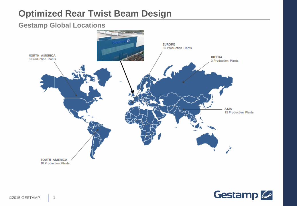
Gestamp Global Locations Optimized Rear Twist Beam Design
2 ©2015 GESTAMP
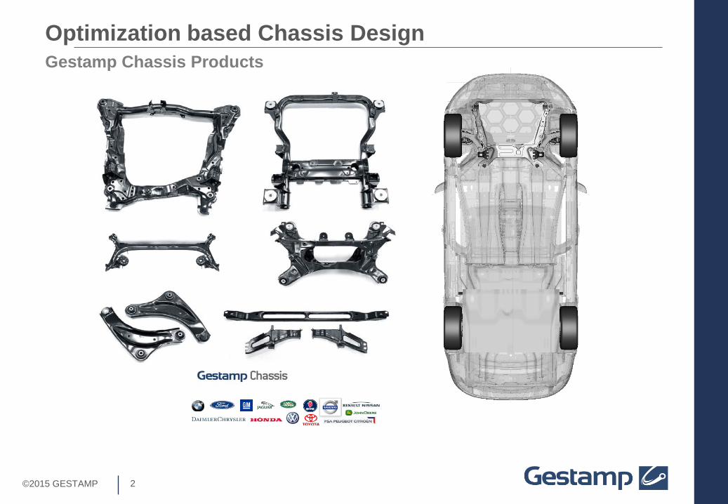
Gestamp Chassis Products Optimization based Chassis Design

3 ©2015 GESTAMP
RTB Suspension System
Rigid trailing arms/side rails with
Body Mounts
Torsion Element
Optimized Rear Twist Beam Design
Reinforcer
Image from Wikipedia

4 ©2015 GESTAMP
Optimized Rear Twist Beam Design Advantages of RTB Rear Suspension
Image from a2mac1.com
5 ©2015 GESTAMP
Optimized Rear Twist Beam Design
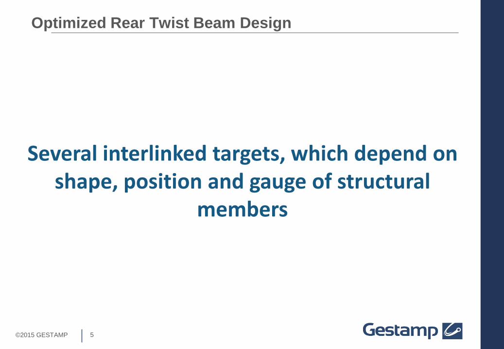
Several interlinked targets, which depend on shape, position and gauge of structural
members

6 ©2015 GESTAMP
Gestamp RTB Design Process
• Initial Information
Optimized Rear Twist Beam Design

7 ©2015 GESTAMP
Key Inputs Defining Basic RTB Geometry
Roll Stiffness = C/∆θ
Optimized Rear Twist Beam Design
Roll Stiffness
A measure of how much the RTB resists the rolling moment of the vehicle. Resistance provided by the torsional rigidity of the Torsion Element.

8 ©2015 GESTAMP
Key Inputs Defining Basic RTB Geometry Optimized Rear Twist Beam Design
Roll Stiffness
A
A
Section Through A - A
Position (x,z)
Shape Gauge
Reinforcer Length

9 ©2015 GESTAMP
Key Inputs Defining Basic RTB Geometry Optimized Rear Twist Beam Design
Roll Steer Steer angle change of rear wheels during vehicle cornering. This can be used to generate “Roll Understeer”.
Turn Direction

10 ©2015 GESTAMP
Key Inputs Defining Basic RTB Geometry Optimized Rear Twist Beam Design
A
A
Section Through A - A
Position (x,z)
Shape
Roll Steer Gauge

11 ©2015 GESTAMP
Key Inputs Defining Basic RTB Geometry Optimized Rear Twist Beam Design
Available Package Space
RTB Designs require minimal space, but the positioning of the fuel tank/spare wheel can influence the design.
Image from a2mac1.com

12 ©2015 GESTAMP
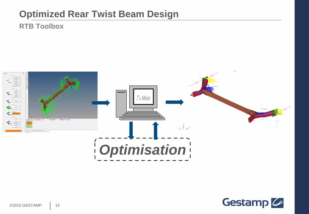
Optimized Rear Twist Beam Design
Gestamp have worked with Altair to develop a method of quickly producing RTB concept
designs which meet K&C and package requirements.
13 ©2015 GESTAMP
RTB Toolbox Optimized Rear Twist Beam Design
Optimisation
14 ©2015 GESTAMP
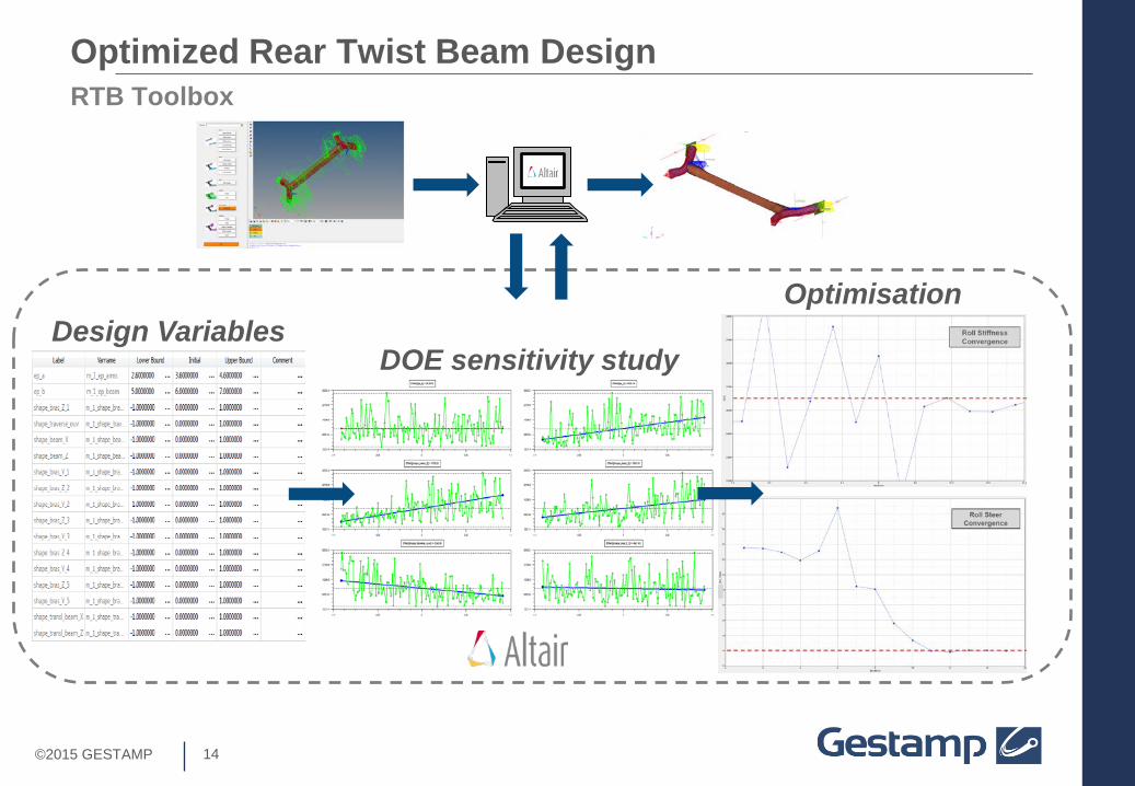
RTB Toolbox
DOE sensitivity study
Optimized Rear Twist Beam Design
Optimisation Design Variables

15 ©2015 GESTAMP
Gestamp RTB Design Process
• Initial “Trial and Error” CAD loop eliminated.
Optimized Rear Twist Beam Design

16 ©2015 GESTAMP
Optimized Rear Twist Beam Design Next Design Stage: Optimisation for Antiphase Durability Target

17 ©2015 GESTAMP
Target Conflict: Roll Stiffness and Antiphase Durability
There is a relationship between the Roll Stiffness and Fatigue Life for the Antiphase Durability Load Case.
Long Reinforcer Thin Gauge Torsion Element
Short Reinforcer Thick Gauge Torsion Element
Mass
Stress
z
y
Optimized Rear Twist Beam Design
18 ©2015 GESTAMP
Optimized Rear Twist Beam Design
There is an optimum combination of reinforcer length and torsion element gauge
for a given Roll Stiffness and Fatigue requirement.

19 ©2015 GESTAMP
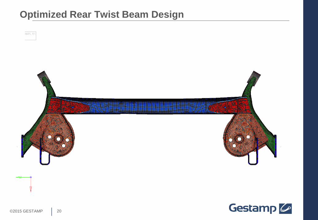
Optimisation of Basic Concept Optimized Rear Twist Beam Design
VARIABLES Length and profile of reinforcer
Section Gauge
OBJECTIVE
20 ©2015 GESTAMP
Optimized Rear Twist Beam Design

21 ©2015 GESTAMP
Optimized Rear Twist Beam Design

22 ©2015 GESTAMP
Optimised Concept Meeting K&C and Durability Requirement
Optimum Length
and shape
Optimum Gauge and
Section
Optimized Rear Twist Beam Design
Mass Minimised
A
A
Section Through A - A
23 ©2015 GESTAMP
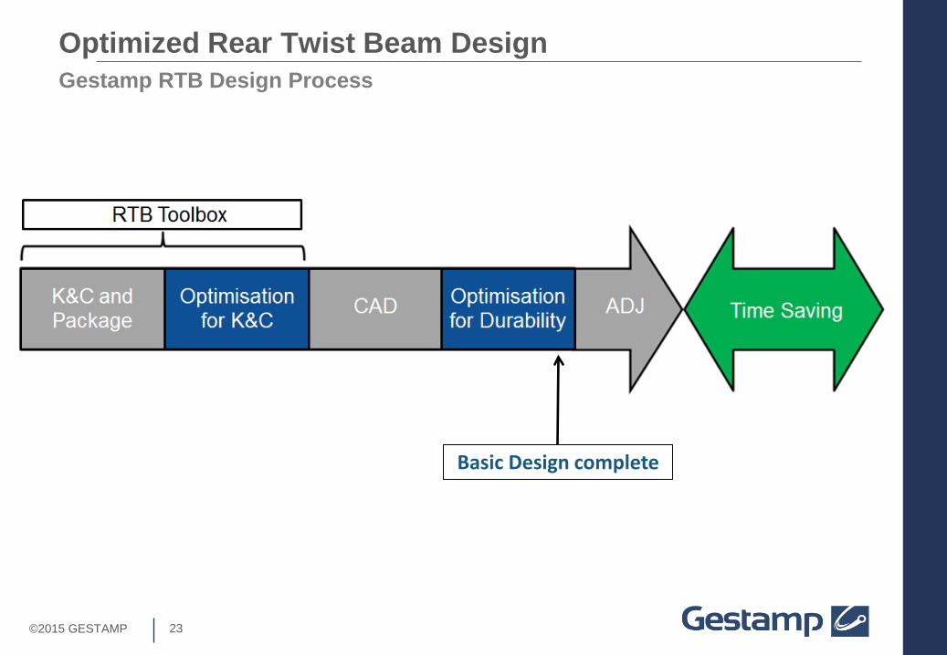
Gestamp RTB Design Process
Basic Design complete
Optimized Rear Twist Beam Design
24 ©2015 GESTAMP
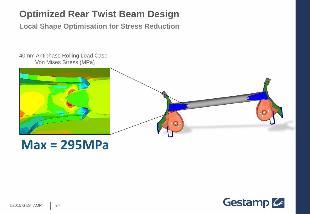
40mm Antiphase Rolling Load Case - Von Mises Stress (MPa)
Local Shape Optimisation for Stress Reduction Optimized Rear Twist Beam Design
Max = 295MPa

25 ©2015 GESTAMP
Moveable control point defining edge shape
• Variables - xy grid co-ordinates of 7control points defining a curve.
• Constraints - Don’t move too far (within bounds of feasible design)
• Objective - minimize the maximum stress in any of the measured elements
Record stress in edge elements
Shape Optimisation for Stress Reduction Optimized Rear Twist Beam Design

26 ©2015 GESTAMP
Moveable control point defining edge shape
Shape Optimisation for Stress Reduction – Iteration 1 Optimized Rear Twist Beam Design

27 ©2015 GESTAMP
Shape Optimisation for Stress Reduction – Iteration 2 Optimized Rear Twist Beam Design

28 ©2015 GESTAMP
Shape Optimisation for Stress Reduction – Iteration 3 Optimized Rear Twist Beam Design

29 ©2015 GESTAMP
Shape Optimisation for Stress Reduction – Iteration 5 Optimized Rear Twist Beam Design

30 ©2015 GESTAMP
295MPa
40mm twist loadcase - Von Mises Stress (MPa) Iteration 0
40mm twist loadcase - Von Mises Stress (MPa) Iteration 9
295MPa 255MPa
Shape Optimisation for Stress Reduction Optimized Rear Twist Beam Design
14% Stress Reduction

31 ©2015 GESTAMP
Gestamp RTB Design Process
Benefit of using an Optimisation led approach
Optimized Rear Twist Beam Design
Typical RTB Design Process
32 ©2015 GESTAMP
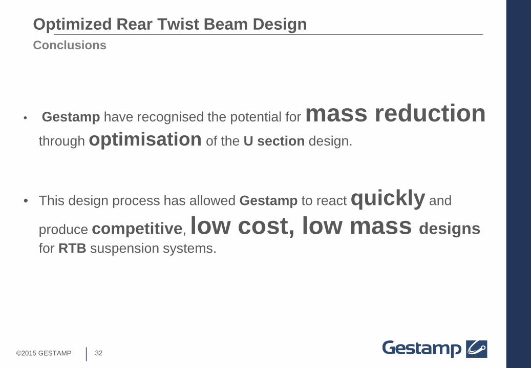
Conclusions Optimized Rear Twist Beam Design
• This design process has allowed Gestamp to react quickly and
produce competitive, low cost, low mass designs for RTB suspension systems.
• Gestamp have recognised the potential for mass reduction through optimisation of the U section design.

©2013 GESTAMP AUTOMOCIÓN
Optimised Rear Twist Beam Design
16/06/15
A Charlesworth


![Stay Fit Optimised[1]](https://static.fdocuments.net/doc/165x107/577d34ea1a28ab3a6b8f27ce/stay-fit-optimised1.jpg)