UIT AN ALTERNATIVE TO THERMAL STRESS RELIEF links/Alternative to Thermal... · UIT AN ALTERNATIVE...
9
- 1 - UIT AN ALTERNATIVE TO THERMAL STRESS RELIEF Speaker’s name: Sam Abston, Director of Engineering and R&D Paper Details: Sam Abston II Director of Engineering and R&D Applied Ultrasonics ABSTRACT: This paper will present the findings of a series of welding procedure qualifications using Ultrasonic Impact Technology (UIT) as a method of stress relief and distortion control. The paper will examine the techniques and methods of applying UIT to a range of mild and high strength steels. The materials selected are based on material requirements employed in mining, off shore, and power generation equipment designs. The weldments were made and tested in accordance with section D1.1 of the AWS welding code. All weldment testing and data recording were performed by independent and certified testing laboratories. The paper will examine and report the results of application of the technology on production equipment. KEYWORDS: Ultrasonic Impact Technology, UIT, Welding of Mild Steel, Welding of High Strength Steel, Stress Relief, Compressive Stress, Mining Equipment, Off Shore Structures, Power Generation Equipment. AUTHOR DETAILS: Sam Abston II Director of Engineering and R&D Applied Ultrasonics Birmingham, Alabama United States
Transcript of UIT AN ALTERNATIVE TO THERMAL STRESS RELIEF links/Alternative to Thermal... · UIT AN ALTERNATIVE...
- 1 -
UIT AN ALTERNATIVE TO THERMAL STRESS RELIEF Speaker’s name: Sam Abston, Director of Engineering and R&D Paper Details: Sam Abston II
Director of Engineering and R&D
Applied Ultrasonics ABSTRACT: This paper will present the findings of a series of welding procedure qualifications using Ultrasonic Impact Technology (UIT) as a method of stress relief and distortion control. The paper will examine the techniques and methods of applying UIT to a range of mild and high strength steels. The materials selected are based on material requirements employed in mining, off shore, and power generation equipment designs. The weldments were made and tested in accordance with section D1.1 of the AWS welding code. All weldment testing and data recording were performed by independent and certified testing laboratories. The paper will examine and report the results of application of the technology on production equipment. KEYWORDS: Ultrasonic Impact Technology, UIT, Welding of Mild Steel, Welding of High Strength Steel, Stress Relief, Compressive Stress, Mining Equipment, Off Shore Structures, Power Generation Equipment. AUTHOR DETAILS: Sam Abston II Director of Engineering and R&D Applied Ultrasonics Birmingham, Alabama United States
- 2 -
UIT AN ALTERNATIVE TO THERMAL STRESS 1. Introduction Ultrasonic Impact Technology (UIT) was developed in Russia during the 70’s to treat welds on the hulls of nuclear submarines. The technology was brought to the United States in the 90’s. It was introduced into industry as a technology that could enhance the properties of materials and extend the life of fabricated structures. A number of universities and other research institutions have conducted research studies to better understand and validate the materials enhancement values of the technology. The research and investigation has resulted in implementation of the technology as standard practice and adoption by codes and standards. The focus of this paper and associated development work is targeted at the application of the technology and its value as an alternate method of stress relief of welds. UIT is a high energy process (27 KHz) that transfers ultrasonic energy into metal by coupling an ultrasonic device with the metal being treated. The ultrasound is transmitted through an indenter that plastically deforms the surface, resulting in a release of surface stress and imparting compressive stress into the structure. The free floating indenters permit the movement of the ultrasonic tool across the surface being treated and/or along the toe or body of a welded structure. The construction of the UIT equipment makes it possible for manual and automatic operation both in field and manufacturing applications. The technology is commonly used to treat the toes and surfaces of welds, changing the weld geometry and imparting compressive residual stress. The process when applied to welded structures will mitigate residual tensile stresses; modify grain structure in the heat affected zone, and adjacent base material. The UIT methods have been successfully used to control distortion and improve fatigue life of welded structures. The range of materials and industries where the technology has been applied is quite diverse, from mild to high strength steels and in industries such as infrastructure, mining equipment, offshore structures, aerospace, and along with others. The technology imparts a compressive residual stress into the material being treated mitigating the residual tensile stress created by welding. Compressive residual stresses have been measured using X-Ray Diffraction methods to a depth of 0.240” (6 mm) in base material. The process of plastically deforming the surface and coupling of the ultrasonic devise with the material being treated permits ultrasound to travel through the treated material softening and altering the grain structure of the fabrication. In turn, relieving residual tensile stress and modifying grain structure in the heat affected zone (HAZ) of weldments. The procedure qualification (PQR) study is being conducted to demonstrate that the UIT process is an effective stress relief method and an alternate to thermal stress relief for the stress relief of weld nuggets and adjacent base material. Based on the transportability and flexibility of the UIT equipment it can be used in manufacturing and field repair conditions. The study was commissioned based on welding related issues experienced by industry. These issues related to the complexity of thermal stress relief along with materials that required a post weld process where thermal stress relief was not recommended. The intent of the study is to weld a series of PQR’s and evaluate the test plates in the as welded, thermal stress relieved, and UIT treated conditions. These PQR test plates will be mechanically tested in accordance with AWS D1.1 PQR procedures. The standard PQR data will be compared and evaluated along with test specimens taken from the PQR test plates for compressive stress depths, charpy impact, and fatigue. The study is at its beginning stages and will continue until all materials requested by industry sponsors have been evaluated. The results of PQR evaluation and study will be compiled and a final report published. The intent of the study is to create an engineering document that can be
- 3 -
used by designers and engineers for selection of a UIT process and procedure that will provide the necessary stress relief of weldments both in manufacturing and field welding applications. 2. Scope of Work and Procedure Qualification Conditions The scope of work is to produce a series procedure qualification (PQ) test plates using a range and combination of materials that are commonly used in fabrication of infrastructure, mining, and offshore platform products and structures. The materials will range from basic carbon steels to high strength steels. In addition, welding methods will also be evaluated to determine optimum method of welding in conjunction with the UIT treatment parameters and methods. The initial PQ plates shall be a single “V” groove weldment in the flat (1G) position. On completion of the 1G testing, other weld groves types and positions shall be welded and evaluated based on requirements by industry. The single “V” groove was selected as a base line for the evaluation providing a simple platform for in process and post weld distortion and weld condition monitoring. The test plate configuration has been designed such that each welded and post welded condition (as welded, thermal stress relief, & UIT treated) shall be subjected to same constraint and welding conditions. A multipass weld shall be made for the full length of the test plates each clamped and restrained equally in a common weld fixture. All essential variables shall be common to each test plates based on the respective WPS with the exception of post weld treatment. As stated above, each test plate shall be subjected to the same conditions for each of the material and welding combinations selected.
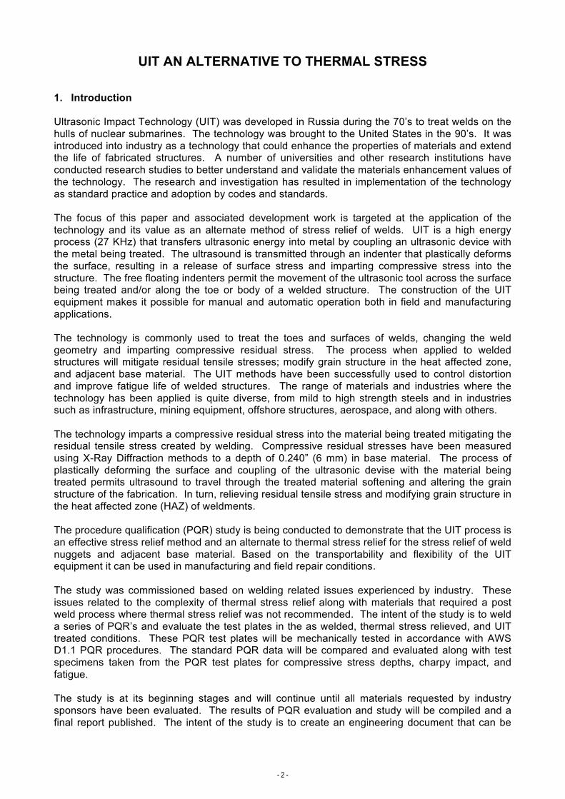
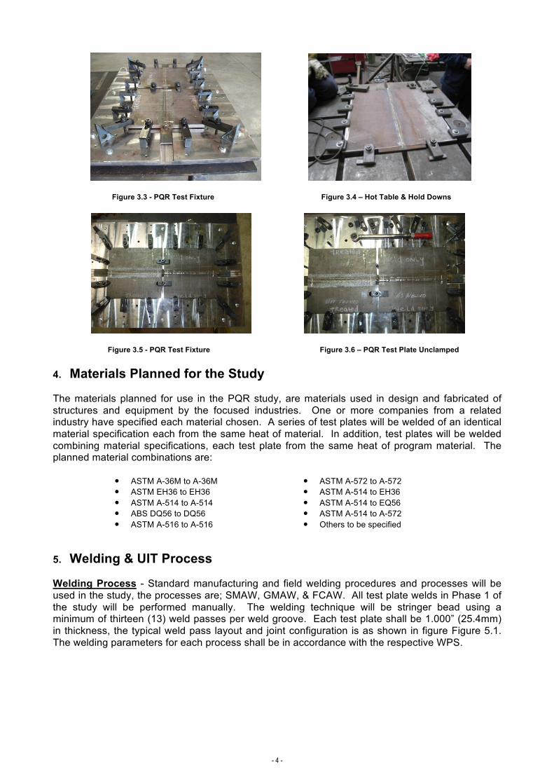
3. Description of Test Plate & Test Fixture The PQR test plates shall be welded and tested in accordance with AWS D1.1 PQR test procedures (figure 3.1). Each test plate shall have five (5) measurement points, these measurement points shall be used to record pre-weld and post weld test plate condition and monitor weld distortion. Each test plate shall be position in accordance with the fixturing work instruction which requires each test plate shall be clamped in eighteen (18) locations. Each clamp position shall be torque to 90 ft Lbs (figure 3.2).
Figure 3.1 – Test Plate Layout Figure 3.2 – PQR Test Fixture The design of the test fixture is intended to restrain the test plate, providing a uniform clamping profile across the test during welding with a uniform stress concentration at the HAZ. The test fixture configuration is intended to simulate simular constrained conditions that are present during component fabrication on existing fabricated structure. The test plate fixture has been design to be portable while providing a uniform and constancy method of test plate constraint for each welded test plate no matter the testing location (figure 3.2 & 3.3). It should be noted that other test plate constraint devices can be used but may not be duplicatable at all locations. A typical example is a standard “Hot Table” layout, reference figure 3.4. The hot table system can provide the necessary constraint but may vary from location to location. For this study, the reinforced portable test fixture will be used in all locations and for all welding positions.
- 4 -
Figure 3.3 - PQR Test Fixture Figure 3.4 – Hot Table & Hold Downs
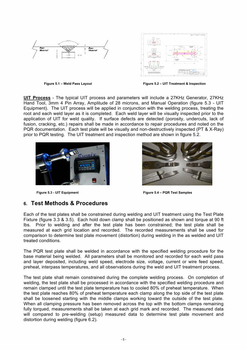
Figure 3.5 - PQR Test Fixture Figure 3.6 – PQR Test Plate Unclamped 4. Materials Planned for the Study The materials planned for use in the PQR study, are materials used in design and fabricated of structures and equipment by the focused industries. One or more companies from a related industry have specified each material chosen. A series of test plates will be welded of an identical material specification each from the same heat of material. In addition, test plates will be welded combining material specifications, each test plate from the same heat of program material. The planned material combinations are:
• ASTM A-36M to A-36M • ASTM EH36 to EH36 • ASTM A-514 to A-514 • ABS DQ56 to DQ56 • ASTM A-516 to A-516
• ASTM A-572 to A-572 • ASTM A-514 to EH36 • ASTM A-514 to EQ56 • ASTM A-514 to A-572 • Others to be specified
5. Welding & UIT Process Welding Process - Standard manufacturing and field welding procedures and processes will be used in the study, the processes are; SMAW, GMAW, & FCAW. All test plate welds in Phase 1 of the study will be performed manually. The welding technique will be stringer bead using a minimum of thirteen (13) weld passes per weld groove. Each test plate shall be 1.000” (25.4mm) in thickness, the typical weld pass layout and joint configuration is as shown in figure Figure 5.1. The welding parameters for each process shall be in accordance with the respective WPS.
- 5 -
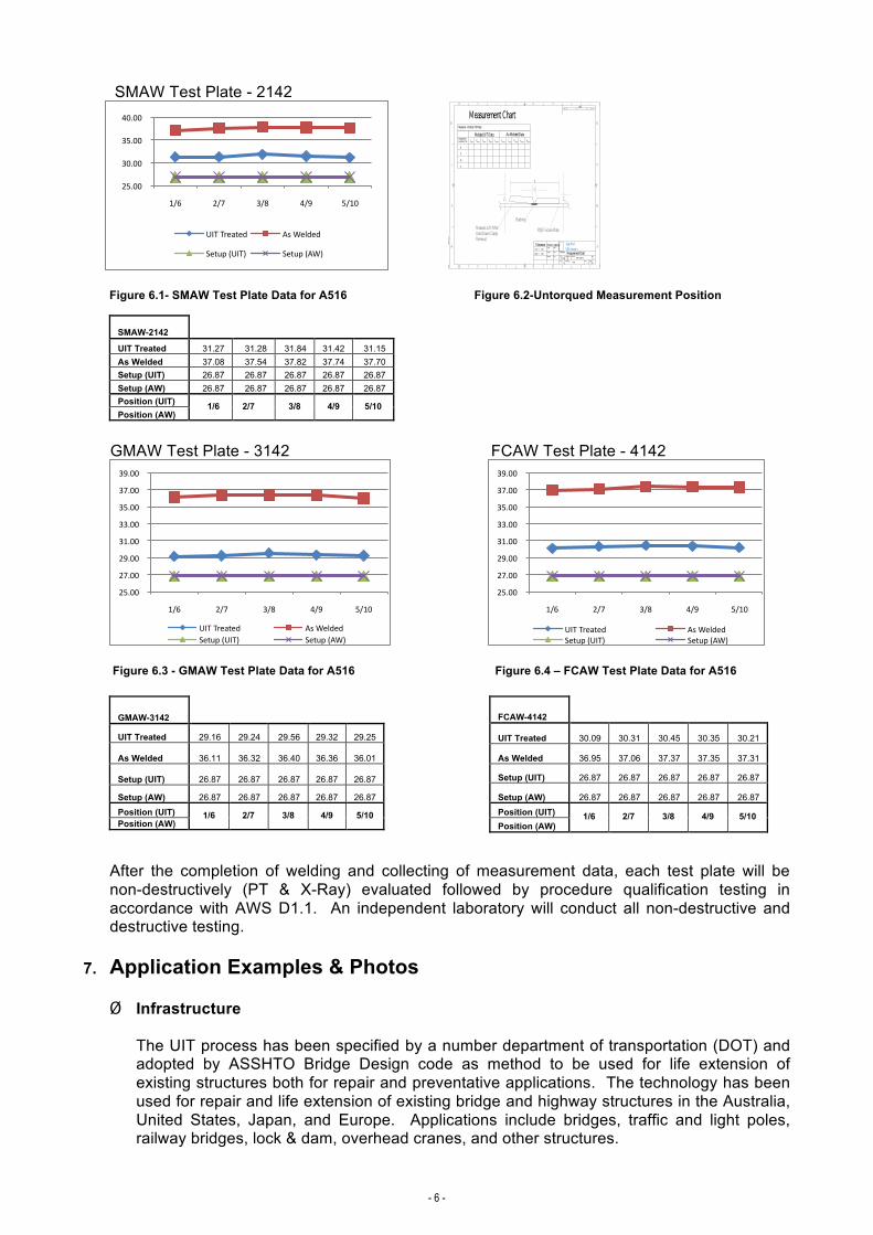
Figure 5.1 – Weld Pass Layout Figure 5.2 – UIT Treatment & Inspection UIT Process - The typical UIT process and parameters will include a 27KHz Generator, 27KHz Hand Tool, 3mm 4 Pin Array, Amplitude of 28 microns, and Manual Operation (figure 5.3 - UIT Equipment). The UIT process will be applied in conjunction with the welding process, treating the root and each weld layer as it is completed. Each weld layer will be visually inspected prior to the application of UIT for weld quality. If surface defects are detected (porosity, undercuts, lack of fusion, cracking, etc.) repairs shall be made in accordance to repair procedures and noted on the PQR documentation. Each test plate will be visually and non-destructively inspected (PT & X-Ray) prior to PQR testing. The UIT treatment and inspection method are shown in figure 5.2.
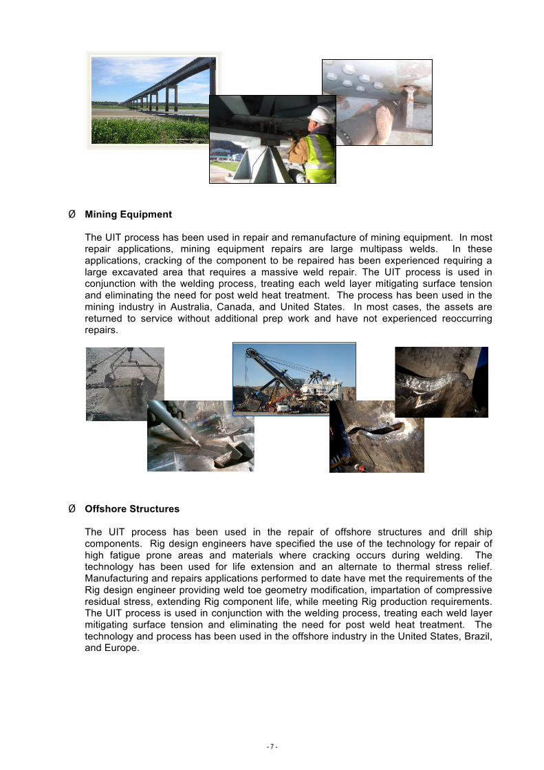
Figure 5.3 - UIT Equipment Figure 5.4 – PQR Test Samples 6. Test Methods & Procedures Each of the test plates shall be constrained during welding and UIT treatment using the Test Plate Fixture (figure 3.3 & 3.5). Each hold down clamp shall be positioned as shown and torque at 90 ft lbs. Prior to welding and after the test plate has been constrained; the test plate shall be measured at each grid location and recorded. The recorded measurements shall be used for comparison to determine test plate movement (distortion) during welding in the as welded and UIT treated conditions. The PQR test plate shall be welded in accordance with the specified welding procedure for the base material being welded. All parameters shall be monitored and recorded for each weld pass and layer deposited, including weld speed, electrode size, voltage, current or wire feed speed, preheat, interpass temperatures, and all observations during the weld and UIT treatment process. The test plate shall remain constrained during the complete welding process. On completion of welding, the test plate shall be processed in accordance with the specified welding procedure and remain clamped until the test plate temperature has to cooled 80% of preheat temperature. When the test plate reaches 80% of preheat temperature each clamp along the top side of the test plate shall be loosened starting with the middle clamps working toward the outside of the test plate. When all clamping pressure has been removed across the top with the bottom clamps remaining fully torqued, measurements shall be taken at each grid mark and recorded. The measured data will compared to pre-welding (setup) measured data to determine test plate movement and distortion during welding (figure 6.2).
- 6 -
SMAW Test Plate - 2142
Figure 6.1- SMAW Test Plate Data for A516 Figure 6.2-Untorqued Measurement Position
SMAW-2142
UIT Treated 31.27 31.28 31.84 31.42 31.15 As Welded 37.08 37.54 37.82 37.74 37.70 Setup (UIT) 26.87 26.87 26.87 26.87 26.87 Setup (AW) 26.87 26.87 26.87 26.87 26.87 Position (UIT) Position (AW)
1/6 2/7 3/8 4/9 5/10
GMAW Test Plate - 3142 FCAW Test Plate - 4142
Figure 6.3 - GMAW Test Plate Data for A516 Figure 6.4 – FCAW Test Plate Data for A516
GMAW-3142
UIT Treated 29.16 29.24 29.56 29.32 29.25
As Welded 36.11 36.32 36.40 36.36 36.01
Setup (UIT) 26.87 26.87 26.87 26.87 26.87
Setup (AW) 26.87 26.87 26.87 26.87 26.87
Position (UIT) Position (AW)
1/6 2/7 3/8 4/9 5/10
FCAW-4142
UIT Treated 30.09 30.31 30.45 30.35 30.21
As Welded 36.95 37.06 37.37 37.35 37.31
Setup (UIT) 26.87 26.87 26.87 26.87 26.87
Setup (AW) 26.87 26.87 26.87 26.87 26.87
Position (UIT) Position (AW)
1/6 2/7 3/8 4/9 5/10
After the completion of welding and collecting of measurement data, each test plate will be non-destructively (PT & X-Ray) evaluated followed by procedure qualification testing in accordance with AWS D1.1. An independent laboratory will conduct all non-destructive and destructive testing.
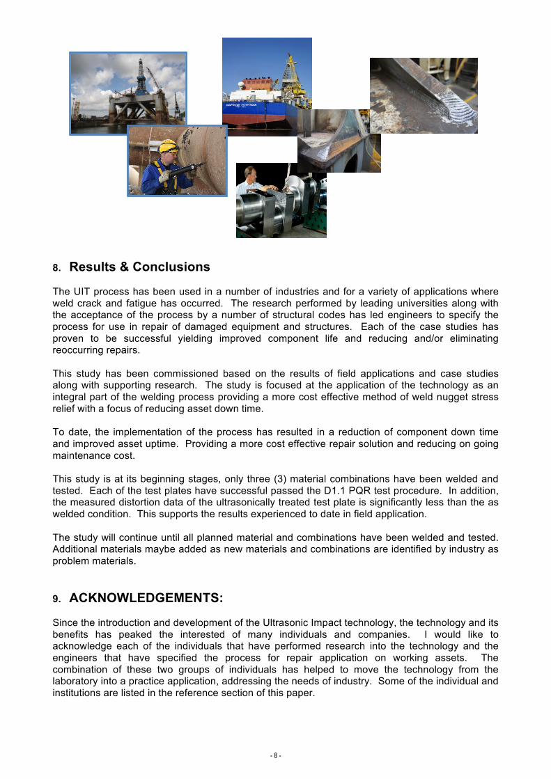
7. Application Examples & Photos
Ø Infrastructure The UIT process has been specified by a number department of transportation (DOT) and adopted by ASSHTO Bridge Design code as method to be used for life extension of existing structures both for repair and preventative applications. The technology has been used for repair and life extension of existing bridge and highway structures in the Australia, United States, Japan, and Europe. Applications include bridges, traffic and light poles, railway bridges, lock & dam, overhead cranes, and other structures.
25.00
30.00
35.00
40.00
1/6 2/7 3/8 4/9 5/10
UITTreated AsWelded
Setup(UIT) Setup(AW)
25.00
27.00
29.00
31.00
33.00
35.00
37.00
39.00
1/6 2/7 3/8 4/9 5/10
UITTreated AsWeldedSetup(UIT) Setup(AW)
25.00
27.00
29.00
31.00
33.00
35.00
37.00
39.00
1/6 2/7 3/8 4/9 5/10
UITTreated AsWeldedSetup(UIT) Setup(AW)
- 7 -
Ø Mining Equipment The UIT process has been used in repair and remanufacture of mining equipment. In most repair applications, mining equipment repairs are large multipass welds. In these applications, cracking of the component to be repaired has been experienced requiring a large excavated area that requires a massive weld repair. The UIT process is used in conjunction with the welding process, treating each weld layer mitigating surface tension and eliminating the need for post weld heat treatment. The process has been used in the mining industry in Australia, Canada, and United States. In most cases, the assets are returned to service without additional prep work and have not experienced reoccurring repairs.
Ø Offshore Structures
The UIT process has been used in the repair of offshore structures and drill ship components. Rig design engineers have specified the use of the technology for repair of high fatigue prone areas and materials where cracking occurs during welding. The technology has been used for life extension and an alternate to thermal stress relief. Manufacturing and repairs applications performed to date have met the requirements of the Rig design engineer providing weld toe geometry modification, impartation of compressive residual stress, extending Rig component life, while meeting Rig production requirements. The UIT process is used in conjunction with the welding process, treating each weld layer mitigating surface tension and eliminating the need for post weld heat treatment. The technology and process has been used in the offshore industry in the United States, Brazil, and Europe.
- 8 -
8. Results & Conclusions
The UIT process has been used in a number of industries and for a variety of applications where weld crack and fatigue has occurred. The research performed by leading universities along with the acceptance of the process by a number of structural codes has led engineers to specify the process for use in repair of damaged equipment and structures. Each of the case studies has proven to be successful yielding improved component life and reducing and/or eliminating reoccurring repairs. This study has been commissioned based on the results of field applications and case studies along with supporting research. The study is focused at the application of the technology as an integral part of the welding process providing a more cost effective method of weld nugget stress relief with a focus of reducing asset down time. To date, the implementation of the process has resulted in a reduction of component down time and improved asset uptime. Providing a more cost effective repair solution and reducing on going maintenance cost. This study is at its beginning stages, only three (3) material combinations have been welded and tested. Each of the test plates have successful passed the D1.1 PQR test procedure. In addition, the measured distortion data of the ultrasonically treated test plate is significantly less than the as welded condition. This supports the results experienced to date in field application. The study will continue until all planned material and combinations have been welded and tested. Additional materials maybe added as new materials and combinations are identified by industry as problem materials.
9. ACKNOWLEDGEMENTS: Since the introduction and development of the Ultrasonic Impact technology, the technology and its benefits has peaked the interested of many individuals and companies. I would like to acknowledge each of the individuals that have performed research into the technology and the engineers that have specified the process for repair application on working assets. The combination of these two groups of individuals has helped to move the technology from the laboratory into a practice application, addressing the needs of industry. Some of the individual and institutions are listed in the reference section of this paper.
- 9 -
REFERENCES:
• Statnikov E.S.: “Physics and mechanism of ultrasonics impact treatment”, IIW Doc.XIII-2004-04, Osaka, Japan, 2004
• Langenecker B.: “Ultrasonic Treatment of Specimens in the Electron Microscope”, The Review of Scientific Instruments 37 (1), 103-106, 1996.
• Shimanki H.: Improvement of Fatigue Strength by UIT, Nippon Steel, July 8, 2010 • Tominaga T., Matsuoka K., Sato K. & Suzuki T.: “Fatigue Improvement of Weld Repaired
Crane Runway Girder by Ultrasonic Impact Treatment”, XIII-2170-07 • Roy S. & Fisher J.W. & Ben T.Y.: “Fatigue Resistance of Welded Details Enhanced by
Ultrasonic Impact Treatment (UIT)”, International Journal of Fatigue, No. 25, 2003, pp. 1239-1247.
• Statnikov E.S.: “Applications of Operational Ultrasonic Impact Treatment (UIT) Technologies in Production of Welded Joints”, 50th Congress of the International Institute of Welding, IIW Doc.XIII-1667-97, San-Francisco, 1997.
• Ushirokawa O. & Nakayama E.: “Stress Concentration Factor at Welded Joints”, Ihikawarima Dihou,Vol.23,No.4,1983.
• Statnikov E.S. and others: “Ultrasound Tool for Strain Strengthening and Relaxation Treatment”, Patent of the RF No 472782, 1975.
• Stanikov E.S.: ”Comparison of Post-Weld Deformation Methods for Increase in Fatigue Strength of Welded Joints, XIII-1668-97 San-Francisco, 1997

![The Vibratory Stress Relief Library · [2], thermal stress relief (TSR) [3,4], vibratory stress relief (VSR) [5-171, etc. TSR is the most widely used and effectively proven technology.](https://static.fdocuments.net/doc/165x107/5ecbbf33ed7da421ca6591c6/the-vibratory-stress-relief-2-thermal-stress-relief-tsr-34-vibratory-stress.jpg)